JP5958876B2 - Vehicle input device - Google Patents
Vehicle input device Download PDFInfo
- Publication number
- JP5958876B2 JP5958876B2 JP2011231688A JP2011231688A JP5958876B2 JP 5958876 B2 JP5958876 B2 JP 5958876B2 JP 2011231688 A JP2011231688 A JP 2011231688A JP 2011231688 A JP2011231688 A JP 2011231688A JP 5958876 B2 JP5958876 B2 JP 5958876B2
- Authority
- JP
- Japan
- Prior art keywords
- steering
- driver
- vehicle
- input device
- camera
- Prior art date
- Legal status (The legal status is an assumption and is not a legal conclusion. Google has not performed a legal analysis and makes no representation as to the accuracy of the status listed.)
- Active
Links
Images


Landscapes
- Fittings On The Vehicle Exterior For Carrying Loads, And Devices For Holding Or Mounting Articles (AREA)
- Steering Controls (AREA)
- User Interface Of Digital Computer (AREA)
Description
この発明は車両の入力装置に係り、特に、運転者による車両機能の操作や搭載機器の操作といった各種操作の入力を行う車両の入力装置に関する。 The present invention relates to an input device for a vehicle, and more particularly to an input device for a vehicle for inputting various operations such as an operation of a vehicle function and an operation of a mounted device by a driver.
車両の入力装置は、運転者による車両機能の操作や搭載機器の操作といった各種操作の入力を行う装置であり、大半がインストルメントパネルや運転席周りに集中して配置されており、その中でもステアリング(ハンドル、ホイール)やコラム部に集中して配置されている。このような入力装置は、スイッチ、レバーの類が一般的である。近年は、ナビゲーション装置やAV機器といった電気機器の表示パネル、カメラ等の光学機器を使った補助入力装置が提案されている。
一般に、機器の各種操作を入力する入力装置は、基本的に操作検知の正確性が求められる。また、ユニバーサルデザインの観点から、幅広いユーザの誰にとっても認識が容易で、かつ操作が簡単であることが必要である。
そして、とくに車両に搭載する入力装置としては、車両を走行させる際に運転操作を行う為の機械的な構造や形状を考慮して設ける必要があり、車両への搭載性を高めるには省スペースであること、運転中でも操作し易いこと、商品としての意匠性(美観を与える)を備えることなどが求められる。
さらに、運転性を損ねない為、また、運転性を補助する為には、運転者に情報を与える視認系の表示装置等は運転者からできるだけ遠くに配置することで、視線移動量を減らし、運転者が操作する操作系のスイッチ類(入力装置)は運転者の近くに配置することが望ましいことがわかっている。
The vehicle input device is a device that inputs various operations such as operation of vehicle functions and on-board equipment by the driver, and most of them are concentrated around the instrument panel and the driver's seat. (Handles, wheels) and the column are concentrated. Such an input device is generally a switch or a lever. In recent years, auxiliary input devices using display devices for electrical devices such as navigation devices and AV devices, and optical devices such as cameras have been proposed.
In general, an input device for inputting various operations of an apparatus is basically required to have accuracy of operation detection. In addition, from the viewpoint of universal design, it is necessary for anyone of a wide range of users to easily recognize and operate.
In particular, as an input device mounted on a vehicle, it is necessary to provide a mechanical structure and shape for performing a driving operation when the vehicle travels. It is required to be easy to operate even during driving, to have a design property (giving aesthetics) as a product.
Furthermore, in order not to impair drivability, and to assist drivability, the visual display device that gives information to the driver is arranged as far as possible from the driver, thereby reducing the amount of eye movement. It has been found that it is desirable to dispose operation switches (input devices) operated by the driver close to the driver.
一般的な機器の各種操作を入力する入力装置には、操作者による所定の操作であるジェスチャをカメラにより撮影し、撮影されたジェスチャに従い機器を制御するものがある。(特開2010−205223号)
また、車両の入力装置には、運転者の前面からインストルメントパネルまでのステリングホイールを含む領域を撮影領域とするカメラを車室の天井に配置し、カメラの撮像から検出された手の握り位置や手を滑らせる方向等の手の状態に基づいて、機器に対する操作入力を設定するものがある。(特開2005−250785号)
カメラを利用した入力装置には、ステアリングホイールにカメラを取り付け、カメラの撮影画像をステアリング操作角度だけ回転させて傾きを補正し、運転者の顔の特徴部分を抽出して居眠りやよそ見を判断するものがある。(特開2010−13090号)
カメラを利用した入力装置には、ステアリングホイールの可動範囲を含む空間を撮像するようにカメラをルームミラー等に配置し、カメラの撮影画像上のステアリングホイールの位置を特定し、カメラの撮影画像から手の位置を特定し、ステアリングホイールの位置と手の位置とを照合してステアリングホイールを把持しているかを判断するものがある。(特開2011−121554号)
カメラを利用した入力装置には、顔認識カメラで取得された顔画像から運転者の覚醒度を推定し、覚醒度合いに応じて警報を発するものがある。(特開2009−248599号)
カメラを利用した入力装置には、運転者を正面から撮像するカメラをステアリングコラムの上面に設け、カメラで取得された顔画像から運転者状態を判定するものがある。(特開2009−248777号)
Some input devices for inputting various operations of a general device take a gesture, which is a predetermined operation by an operator, with a camera, and control the device according to the photographed gesture. (Japanese Patent Laid-Open No. 2010-205223)
In addition, in the vehicle input device, a camera whose shooting area is an area including the steering wheel from the front of the driver to the instrument panel is arranged on the ceiling of the passenger compartment, and the hand grip position detected from the imaging of the camera Some devices set operation inputs to devices based on the state of the hand such as the direction in which the user slips. (Japanese Patent Laid-Open No. 2005-250785)
In the input device using the camera, the camera is attached to the steering wheel, and the image taken by the camera is rotated by the steering operation angle to correct the tilt, and the characteristic part of the driver's face is extracted to determine whether the driver is snoozing or looking away There is something. (Japanese Patent Laid-Open No. 2010-13090)
In the input device using a camera, the camera is placed on a room mirror or the like so as to capture the space including the movable range of the steering wheel, the position of the steering wheel on the camera image is specified, and There are some which determine the position of the hand and determine whether the steering wheel is gripped by comparing the position of the steering wheel and the position of the hand. (Japanese Patent Laid-Open No. 2011-12155 4 )
Some input devices using a camera estimate a driver's arousal level from a face image acquired by a face recognition camera and issue a warning according to the arousal level. (Japanese Patent Laid-open No. 2009-2485 9 No. 9)
Some input devices using a camera are provided with a camera that images the driver from the front on the top surface of the steering column, and determine the driver state from a face image acquired by the camera. (Japanese Unexamined Patent Application Publication No. 2009-248777)
しかし、前記公報に開示されるカメラを用いた入力装置は、機器の各種操作を入力する入力装置として表示系と融合した使用方法となっておらず、運転操作を行う為の機械的な構造や形状によって著しく制限された配置となっており、主要な入力装置とするには改善の余地がある。 However, the input device using the camera disclosed in the above publication is not a usage method fused with a display system as an input device for inputting various operations of the device. The arrangement is significantly limited by the shape, and there is room for improvement in the main input device.
この発明は、入力装置を構成する機器を最適な配置とし、運転者による所定の操作の誤った識別検知に基づく機器の誤動作を防止でき、また、実質的に幅狭く所定の操作を行う空間を設けることができ、搭載性に優れ、小さな運転席でも運転者の占有空間を広く採ることができ、運転者にとってアクセス容易で利便性が良い車両の入力装置を実現することを目的とする。 According to the present invention, the devices constituting the input device are optimally arranged to prevent malfunction of the device based on erroneous identification detection of the predetermined operation by the driver, and the space for performing the predetermined operation is substantially narrow. An object of the present invention is to realize a vehicle input device that can be provided, has excellent mountability, can occupy a driver's occupied space even in a small driver's seat, and is easily accessible and convenient for the driver.
この発明は、車両を操舵するためのステアリングと、前記ステアリングに対して車両前方に位置し、前記ステアリングが設けられたインストルメントパネルに配置されたカメラと、前記カメラの出力から車両乗員の操作を検知するジェスチャ検知手段とを備えた車両の入力装置であって、前記ステアリングの中立時は前記カメラが前記車両のルーフパネルを指向し、前記ステアリングが回動操作されている間は、前記ステアリングよりも車両後方側から見て前記カメラが該ステアリングによって覆われることを特徴とする。 The present invention provides a steering for steering a vehicle, a camera located in front of the vehicle with respect to the steering and disposed on an instrument panel provided with the steering, and an operation of a vehicle occupant from the output of the camera. an input device for the vehicle with a gesture detection means for detecting, at the neutral position of the steering is directed to a roof panel of the camera the vehicle, while the steering is rotationally operated, from the steering The camera is covered with the steering when viewed from the rear side of the vehicle .
この発明は、インストルメントパネルに配置されたカメラが、ステアリングの中立時にルーフパネルを指向し、ステアリングが回動操作されている間はステアリングよりも車両後方側から見て該ステアリングによって覆われるので、車両乗員の操作(ジェスチャ操作)を車両の直進走行時にのみ認識できる配置としており、ステアリングの回動操作による旋回走行中に車両乗員による操作入力を識別検知することがないため、操作入力の誤った識別検知に基づく機器の誤動作を防止できる。
この発明は、ステアリングに対するカメラの配置によって、実質的に幅狭く操作を行う空間(検知対象空間)を設けており、入力装置の搭載空間を小さくすることができ、搭載性に優れる為、小さなシートでも車両乗員の占有空間を広く採ることができ、車両乗員にとってアクセス容易であるので利便性が良い。
In the present invention, the camera disposed on the instrument panel is directed to the roof panel when the steering is neutral , and is covered by the steering when viewed from the vehicle rear side rather than the steering while the steering is being rotated . The vehicle occupant's operation (gesture operation) can be recognized only when the vehicle is traveling straight ahead, and the operation input by the vehicle occupant is not detected during turning by turning the steering. It is possible to prevent malfunction of the device based on the identification detection.
According to the present invention, a space (detection target space) for performing a substantially narrow operation is provided depending on the arrangement of the camera with respect to the steering wheel, so that the mounting space of the input device can be reduced and the mounting property is excellent. However, the space occupied by the vehicle occupant can be widened, and it is easy for the vehicle occupant to access, which is convenient.
以下、図面に基づいて、この発明の実施例を説明する。 Embodiments of the present invention will be described below with reference to the drawings.
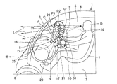
図1〜図5は、この発明の実施例を示すものである。図1において、1は車両、2はフロアパネル、3はフロントシールド、4はルーフパネル、5は車室、6は車輪である。車両1は、車室5内のフロアパネル2上にシート7を設置し、シート7前方のウィンドウシールド3下部にインストルメントパネル8を設けている。インストルメントパネル8には、シート7に着座した運転者Dと正対する位置にステアリングコラム9により車輪6を操舵するステアリング10を取り付けている。
ステアリング10は、図2に示すように、ステアリングコラム9に回転可能に支持される円板形状のステアリングパッド11と、ステアリングパッド11の下部に外方に突出させた左右一対のステー部12・13と、ステー部12・13からステアリングパッド11の外周に沿い上方に延設した左右一対のグリップ14・15とを備えている。
前記車両1は、運転者Dと正対する位置のインストルメントパネル8とステアリングコラム9とステアリング10とに、入力装置16を配置している。入力装置16は、ステアリング10のグリップ14・15前方のステアリングコラム9に設けた左右一対のコンビネーションレバースイッチ17・18と、ステアリング10のグリップ14・15上端の対向する各端部に設けた左右一対のプッシュスイッチ19・20と、ステアリングパッド11に設けたタッチパッド21と、ステアリング10より前方のインストルメントパネル8に配けた距離画像カメラ22による検知対象空間23と、の各操作入力手段からなる。
これらの操作入力手段の実質的な配置は、ほぼ一杯に延ばした運転者Dの両腕をその肩を中心に動かした際に手先が描く、上下左右に延びる略平面上に沿って手が届く範囲の操作入力領域Sとなっている。運転者Dの手が届く操作入力領域Sの下半分は、運転者Dが直接手で触れて操作するタッチ操作領域S1である。タッチ操作領域S1には、コンビネーションレバースイッチ17・18と、プッシュスイッチ19・20と、タッチパッド21とを配置している。また、運転者Dの手が届く操作入力領域Sの上半分は、運転者Dが直接出で触れることなく空間で操作を行うジェスチャ操作領域S2である。ジェスチャ操作領域S2には、距離画像カメラ22による検知対象空間23を配置している。
1 to 5 show an embodiment of the present invention. In FIG. 1, 1 is a vehicle, 2 is a floor panel, 3 is a front shield, 4 is a roof panel, 5 is a passenger compartment, and 6 is a wheel. In the vehicle 1, a
As shown in FIG. 2, the
In the vehicle 1, an
The substantial arrangement of these operation input means allows the hand to reach along a substantially flat surface extending vertically and horizontally, which is drawn by the hand when the arms of the driver D, which are almost fully extended, are moved around the shoulders. The operation input area S is a range. The lower half of the operation input area S that can be reached by the driver D is a touch operation area S1 that the driver D directly touches and operates. In the touch operation area S1,
前記距離画像カメラ22は、投影的に拡散する三次元形状の検知対象空間23を形成するよう視野角Vを持ち、検知対象空間23において対象物までの距離を二次元画像化して出力するカメラである。距離画像カメラ22は、検知部24による三角測量の原理を利用している為、距離を検知するセンサが複数ある。それらセンサの離間距離が距離検出精度にも影響するため、距離画像カメラ22の配置には設置幅を確保する必要がある。
この実施例では、図2に示すように、ステアリング10よりも車体前方に設けたインストルメントパネル8の上面から運転者D側の後面にかけて湾曲する面に、幅方向に向かって水平方向に延びる検出窓25を形成している。距離画像カメラ22は、検知部24が検出窓25に向くようにインストルメントパネル8の内部に収納し、図示しない車体構造部(ステアリングサポートメンバ)の取付部に支持している。
距離画像カメラ22は、検知部24による視野角Vの中心軸Cが検出窓25を通り後上方の車両1のルーフパネル4を指向するように配置してある。視野角Vの範囲では、直接的に運転者Dの身体が検知対象空間23に入らない姿勢であり、視野角Vの検知対象空間23と運転者Dの身体との間に非検知空間26を形成する姿勢として、距離画像カメラ22はインストルメントパネル8内に支持している。距離画像カメラ22の取付角度は、個々の車両1における運転姿勢や、ステアリング取付角度などの配置や形状に応じて、変更して設定すれば良い。
距離画像カメラ22は、シート7に着座した運転者Dから見て、図3・図4に示すように、ステアリング10を回動操作した際のグリップ14・15による最外軌跡に囲まれる範囲に収まるよう配置してある。距離画像カメラ22は、この配置により、その存在を運転者Dに意識させ難くでき、距離画像カメラ22の検知部24が検知機能を確保する為に必要とする設置幅を確保できる。なお、この距離画像カメラ22の設置位置に、コーションランプやインジケータを併設することは可能である。
The
In this embodiment, as shown in FIG. 2, detection that extends in the horizontal direction toward the width direction on a surface that curves from the upper surface of the
The
When viewed from the driver D seated on the
前記ステアリング10は、運転者Dが両手それぞれで握る左右一対のグリップ14・15上端の各端部間に空間27を備えている。ステアリング10には、回動操作した際の角度を検知する角度検知手段28を備えている(図5参照)。なお、ステアリング10は、回動軸で連結した機械式、ステア・バイ・ワイヤ方式のいずれでも良い。グリップ14・15に挟まれる空間27は、ステアリング10の中立時に車両上方に向くように位置している。ステアリング10が中立時のグリップ14・15に挟まれる空間27には、前記距離画像カメラ22の視野角Vを有する検知対象空間23の少なくとも一部を一致させるように、距離画像カメラ22を配置している。
検知対象空間23とグリップ14・15に挟まれる空間27との重なり合った空間では、タッチ操作領域S1とジェスチャ操作領域S2が空間を共有し合い、ジェスチャ操作領域S2を含めた全体をコンパクトにできると同時に、運転者Dからのアクセスの良さにより、使い勝手の良い入力装置16を提供することができる。また、入力装置16は、グリップ14・15上端の間に掌を広げた程度の面積を確保した検知対象空間23を確保する事によって、検知対象空間23を無駄に大きくする必要がなく、運転者Dの手によるジェスチャを行うのに充分な空間を確保することができる。
このように、入力装置16は、距離画像カメラ22の検知対象空間23の一部をステアリング10の中立時におけるグリップ14・15に挟まれる空間27に一致させるように距離画像カメラ22を配置したことで、検知対象空間23内での運転者Dによる所定の操作(ジェスチャ操作)を車両1の直進走行時にのみ認識できる配置としており、図4に示すように、グリップ14・15で検知対象空間23を覆うことで、ステアリング10の回動操作による旋回走行中に運転者Dが所定の操作をし辛くして、所定の操作入力の誤った識別検知に基づく機器の誤動作を防止できる。
また、入力装置16は、ステアリング10のグリップ14・15に対する距離画像カメラ22の配置によって、実質的に幅狭く所定の操作を行う検知対象空間23を設けており、入力装置16の搭載空間を小さくすることができ、搭載性に優れる為、小さなシート7でも運転者Dの占有空間を広く採ることができ、運転者Dにとってアクセス容易であるので利便性が良い。
The steering 10 includes a
In the space where the
Thus, the
In addition, the
この入力装置16は、図5に示すように、検知対象空間23内の対象物(この実施例においては運転者Dの手)までの距離を二次元画像化して出力する前記距離画像カメラ22と、ステアリング10の回動操作した際の角度を検知する前記角度検知手段28と、距離画像カメラ22の出力から人為的な所定の操作入力を識別して検知するジェスチャ検知手段29とを備えている。
前記ジェスチャ検知手段29が検知した所定の操作入力は、車内LAN(CAN)30等により各種の制御装置31〜34に出力され、機器を制御する。例えば、制御装置31は、所定の操作入力に従い後述する表示装置のスクリーン35を制御する。制御装置32は、所定の操作入力に従い空調装置を制御する。制御装置33は、所定の操作入力に従い音響機器を制御する。制御装置34は、所定の操作入力に従い他の制御装置を制御する。
前記入力装置16のジェスチャ検知手段29は、旋回走行中のようにステアリング10に回動角が与えられる操舵状態では、角度検知手段28の検出するステアリング10の回動角が所定角度(例えば、中立付近となる回動中心に左右両方向の微少な不感帯を含めた範囲の中立角度を超える角度)を超える場合に、非直進走行時、旋回走行中等と判定し、距離画像カメラ22による検知対象空間23の判断を一時的に中止する。
図4に示すように、ステアリング10を回動操作した時点で、グリップ14・15およびそれを握る運転者Dの手によってジェスチャ操作領域S2の下部空間の検出窓25が遮られ、実質的にジェスチャ操作領域S2が削られて判断できない状態となるが、ジェスチャ検知手段29は判断を中止することで誤判断に基づく誤動作をなくすことができる。
これにより、ジェスチャ操作という曖昧な入力状態が存在する入力装置16としても、周囲の安全を認識しやすい直進時にのみジェスチャ操作可能とし、右左折やレーン変更などステアリング回動操作時に運転者Dのながら操作や誤動作を防ぐという運転席環境を実現することができる。
As shown in FIG. 5, the
The predetermined operation input detected by the
In the steering state in which the turning angle is given to the
As shown in FIG. 4, when the
As a result, even if the
前記入力装置16は、図1に示すように、ジェスチャ操作領域S2を通して運転者Dが車両前方を見る際の視線Lの先に、集中表示領域となるインストルメントパネル8の上部に表示装置を設けている。ここでは、ステアリング10に正対してシート7に着座する運転者Dの視線Lが、距離画像カメラ22の視野角Vで与えられる検知対象空間23を通過した前方あって、かつ、インストルメントパネル8上からウィンドシールド3までの間に、表示装置であるヘッドアップディスプレイ(HUD)のスクリーン35を設けている。スクリーン35には、図2に示すように、インストルメントパネル8に設置したプロジェクタ36から映像が投射される。
入力装置16は、距離画像カメラ22の視野角Vが、ステアリング10の左右一対のグリップ14・15の鉛直上方位置で視線Lと交差するように距離画像カメラ22を設置する。図1において、符号P1は距離画像カメラ22の視野角Vで与えられる検知対象空間23の等距離面(平面)であり、符号P2は等距離面P1と交差して運転者Dが想定する操作面(仮想平面)である。
スクリーン35は、図1に示すように、運転者Dの視線L上でジェスチャ操作領域S2と重なっている。ジェスチャ操作領域S2は、ステアリング10の左右一対のグリップ14・15に挟まれる位置からスクリーン35にかけて掌程度の空間を確保できる。なお、スクリーン35は、専用のスクリーンをインストルメントパネル8上に設けるか、ウィンドシールド3に偏光フィルムを貼るなどして、スクリーンとすることができる。
この入力装置16は、運転者Dの視線Lの延長上で距離画像カメラ22の検知対象空間23を通過した前方に表示装置のスクリーン35を設けているので、運転者Dの視線移動を少なくするとともに、運転者Dはのスクリーン35の表示を見ながら所定の操作を行うことができ、利便性を高めることができる。
また、入力装置16は、運転者Dの面前や胸元から離れた位置に検知対象空間23を設けており、運転者Dの面前や胸元といった日常動作が行われる至近距離の空間を非検知対象空間32としているので、所定の操作入力の誤った識別検知に基づく機器の誤動作を防止できる。
As shown in FIG. 1, the
The
As shown in FIG. 1, the
Since this
Further, the
前記スクリーン35に表示する画像内容の一例として、選択肢に対応した手によるジェスチャの形を簡易表示する。運転者Dは、スクリーン35の表示内容を見ながら実際の手のジェスチャを行えば良いので、ジェスチャをわざわざ覚える必要がなく、また、この配置により、運転者Dは視線Lの移動距離が極めて少なくて済み、焦点距離の調整幅も少なくて済むので、車両周囲への注意が疎かになる可能性を下げることができる。
スクリーン35に表示する画像内容の例2として、選択肢のボタン(選択肢領域)を縦方向(上下方向)に長さを確保するよう表示設定し、ジェスチャを行う位置と連動するように設定すれば、運転者Dが正対するよう背筋を延ばしてシート7に座ることは自分で調整できるので、運転者Dの視点高さ位置が体格によって変わっても、選択操作を正確に判別できるように対応させることができる。つまり、入力装置16として操作入力検知の正確性を確保できる。
ジェスチャ操作領域S2は、ステアリングパッド11の上端から上方に連続し、運転者Dが車両前方を見る際の視線Lをカバーする範囲までにわたり広い範囲を提供できる。運転者Dの座高が異なり、視点が異なる幅広いユーザに対して適応させることができる。とくに小柄な運転者Dに対しては、上下に連続したジェスチャ操作領域S2は有効である。また、ステアリング部分を避けて設置する必要がなく、距離画像カメラ22が出力する距離画像のステアリング部分を処理する必要が少ない。
なお、この車両1は、表示装置としては、インストルメントパネル8上からウィンドシールド3までの間に設けたスクリーン35だけでなく、インストルメントパネル8の左側に左サイドビューモニタ37を設け、インストルメントパネル8の右側に右サイドビューモニタ38を設けている。
As an example of the image content displayed on the
As an example 2 of the image content displayed on the
The gesture operation region S2 is continuous upward from the upper end of the
The vehicle 1 is provided with not only a
前記入力装置16は、図3に示すように、ステアリング10の左右一対となるグリップ14・15に囲まれる空間39の中央にステアリングパッド11を設けている。ステアリングパッド11の上部には、グリップ14・15に挟まれる空間27に上端を臨ませてタッチパッド21を配置している。タッチパッド21は、ステアリングパッド11の上部のスロット40に着脱自在に装着されている。タッチパッド21は、表示画面上にタッチパネル層を重ねたタッチパネル41を有する後世代携帯端末等とすることができる。タッチパッド21においても、タッチパネル41の表示を、一本の指を使って、選択するだけでなく、上下左右にスクロールしたり、複数の指を使って、拡大、縮小したりする、運転者Dの手によるジェスチャ操作入力が可能である。
このように、入力装置16は、実質的にステアリングパッド11の幅より狭いタッチパッド21を上部に配置し、そのタッチパッド21の上端を検知対象空間23と一致するグリップ14・15に挟まれる空間27に臨ませているので、タッチパッド21から上方に続くように運転者Dが所定の操作を行う空間(検知対象空間23)を設け、タッチパッド21への接触操作と所定の操作(ジェスチャ操作)による非接触操作とを組み合わせたコンパクトな操作入力手段を設けることができ、搭載性に優れる為、小さなシート7でも運転者Dの占有空間を広く操ることができ、運転者Dにとってアクセス容易であるので利便性が良い。
また、この入力装置16は、ステアリング10の回転中心よりも上方に、コンビネーションレバースイッチ17・18、プッシュスイッチ19・20、タッチパッド21、検知対象空間23の各操作入力手段を、最外端のコンビネーションレバースイッチ17・18を結ぶ線分を底として上方に向かいタッチパッド21、プッシュスイッチ19・20、検知対象空間23を三角形状となるように集中配置している。これにより、入力装置6は、接触操作のコンビネーションレバースイッチ17・18、プッシュスイッチ19・20に対して、所定の操作(ジェスチャ操作)による非接触操作の検知対象空間23が上下に繋がるように操作入力領域Sを形成することができる。
さらに、この入力装置16は、ステアリング10の回転中心の周囲を集中表示領域として、運転者Dに対する情報の表示装置を配置している。運転者Dに対する情報の表示装置としては、インストルメントパネル8の上部のヘッドアップディスプレイ(HUD)のスクリーン35と、その左右両側に一対のサイドビューモニタ37・38を設けてある。前述したタッチパッド21も、携帯端末とすることで、前記制御装置31〜34を含む車載制御装置と通信を介して連携することにより、タッチパネル41がサブモニタとして機能する。
As shown in FIG. 3, the
In this way, the
Further, the
Further, the
この発明は、入力装置を構成する機器を最適な配置とすることで、所定の操作の誤った識別検知に基づく機器の誤動作を防止し、また、実質的に幅狭く所定の操作を行う空間を設けることができ、アクセス容易で利便性が良い車両の入力装置を実現できるものであり、四輪車だけでなく、二輪車においても応用可能である。 The present invention prevents the malfunction of the device based on the erroneous identification detection of the predetermined operation by arranging the devices constituting the input device in an optimal manner, and also makes a space for performing the predetermined operation substantially narrow. It is possible to provide a vehicle input device that is easy to access and convenient, and can be applied not only to four-wheeled vehicles but also to two-wheeled vehicles.
1 車両
2 フロアパネル
3 フロントシールド
7 シート
8 インストルメントパネル
9 ステアリングコラム
10 ステアリング
11 ステアリングパッド
14・15 グリップ
16 入力装置
17・18 コンビネーションレバースイッチ
19・20 プッシュスイッチ
21 タッチパッド
22 距離画像カメラ
23 検知対象空間
25 検出窓
26 非検知空間
27 グリップ14・15に挟まれる空間
28 角度検知手段
29 ジェスチャ検知手段
30 車内LAN(CAN)
31〜34 制御装置
35 スクリーン
36 プロジェクタ
37 右サイドビューモニタ
38 左サイドビューモニタ
41 タッチパネル
D 運転者
S 操作入力領域
S1 タッチ操作領域
S2 ジェスチャ操作領域
DESCRIPTION OF SYMBOLS 1
31-34
Claims (2)
Priority Applications (1)
| Application Number | Priority Date | Filing Date | Title |
|---|---|---|---|
| JP2011231688A JP5958876B2 (en) | 2011-10-21 | 2011-10-21 | Vehicle input device |
Applications Claiming Priority (1)
| Application Number | Priority Date | Filing Date | Title |
|---|---|---|---|
| JP2011231688A JP5958876B2 (en) | 2011-10-21 | 2011-10-21 | Vehicle input device |
Publications (3)
| Publication Number | Publication Date |
|---|---|
| JP2013086750A JP2013086750A (en) | 2013-05-13 |
| JP2013086750A5 JP2013086750A5 (en) | 2014-08-21 |
| JP5958876B2 true JP5958876B2 (en) | 2016-08-02 |
Family
ID=48531083
Family Applications (1)
| Application Number | Title | Priority Date | Filing Date |
|---|---|---|---|
| JP2011231688A Active JP5958876B2 (en) | 2011-10-21 | 2011-10-21 | Vehicle input device |
Country Status (1)
| Country | Link |
|---|---|
| JP (1) | JP5958876B2 (en) |
Families Citing this family (9)
| Publication number | Priority date | Publication date | Assignee | Title |
|---|---|---|---|---|
| DE102013012777A1 (en) * | 2013-07-31 | 2015-02-05 | Valeo Schalter Und Sensoren Gmbh | Method for using a communication terminal in a motor vehicle when activated autopilot and motor vehicle |
| US20150185858A1 (en) * | 2013-12-26 | 2015-07-02 | Wes A. Nagara | System and method of plane field activation for a gesture-based control system |
| DE102014200782A1 (en) * | 2014-01-17 | 2015-07-23 | Bayerische Motoren Werke Aktiengesellschaft | Operating a vehicle according to the desire of a vehicle occupant |
| JP6413647B2 (en) * | 2014-10-31 | 2018-10-31 | 三菱自動車工業株式会社 | Operation input device |
| JP6464681B2 (en) * | 2014-11-05 | 2019-02-06 | 三菱自動車工業株式会社 | Operation input device |
| DE102014116292A1 (en) * | 2014-11-07 | 2016-05-12 | Visteon Global Technologies, Inc. | System for transmitting information in a motor vehicle |
| JP6342874B2 (en) * | 2015-11-24 | 2018-06-13 | 矢崎総業株式会社 | Image recognition device |
| JP2017109537A (en) * | 2015-12-15 | 2017-06-22 | ダイムラー・アクチェンゲゼルシャフトDaimler AG | Driver monitoring camera arrangement structure |
| WO2022259794A1 (en) * | 2021-06-09 | 2022-12-15 | 株式会社デンソー | Occupant imaging device |
Family Cites Families (8)
| Publication number | Priority date | Publication date | Assignee | Title |
|---|---|---|---|---|
| JP3796840B2 (en) * | 1996-09-27 | 2006-07-12 | 日産自動車株式会社 | Gesture input device and input device including the same |
| JP2000075991A (en) * | 1998-08-28 | 2000-03-14 | Aqueous Research:Kk | Information input device |
| JP2005032895A (en) * | 2003-07-10 | 2005-02-03 | Hitachi Cable Ltd | Dicing method |
| JP2005250322A (en) * | 2004-03-08 | 2005-09-15 | Matsushita Electric Ind Co Ltd | Display device |
| JP2006298003A (en) * | 2005-04-15 | 2006-11-02 | Nissan Motor Co Ltd | Command input device |
| JP2006312346A (en) * | 2005-05-06 | 2006-11-16 | Nissan Motor Co Ltd | Command input device |
| JP2007069680A (en) * | 2005-09-05 | 2007-03-22 | Toyota Motor Corp | Mounting structure of face image taking camera |
| JP5247389B2 (en) * | 2008-12-01 | 2013-07-24 | 富士通テン株式会社 | Display device |
-
2011
- 2011-10-21 JP JP2011231688A patent/JP5958876B2/en active Active
Also Published As
| Publication number | Publication date |
|---|---|
| JP2013086750A (en) | 2013-05-13 |
Similar Documents
| Publication | Publication Date | Title |
|---|---|---|
| JP5958876B2 (en) | Vehicle input device | |
| US10613810B2 (en) | Display device for vehicle | |
| JP6682574B2 (en) | Method of using a communication terminal in a motor vehicle with an autopilot operating and motor vehicle | |
| US9645640B2 (en) | Device and method for navigating within a menu for controlling a vehicle, and selecting a menu entry from the menu | |
| JP5899251B2 (en) | Vehicle input device | |
| KR20170109283A (en) | Vehicle and method for controlling vehicle | |
| KR102051606B1 (en) | Electronic apparatus for vehicle | |
| WO2014156614A1 (en) | Vehicular display device | |
| JP6464869B2 (en) | Operation system | |
| JP2015133603A (en) | Periphery monitoring device, and program | |
| JP2007302116A (en) | Operating device of on-vehicle equipment | |
| JP5382313B2 (en) | Vehicle operation input device | |
| JP2018090223A (en) | Display device for vehicle | |
| JP2010173410A (en) | Function display device | |
| JP5903319B2 (en) | Vehicle display device | |
| KR101714077B1 (en) | Viewing angle control system of rear perception camera for vehicle | |
| JP2018103646A (en) | Vehicular information display device and vehicular information display program | |
| JP2007062668A (en) | Input device for vehicle | |
| US9536414B2 (en) | Vehicle with tactile information delivery system | |
| JP2018103866A (en) | Visual recognition device for vehicle | |
| JP2017149425A (en) | Vehicle display device | |
| JP6166931B2 (en) | Vehicle display device | |
| JP6236211B2 (en) | Display device for transportation equipment | |
| JP2014219682A (en) | Display control system and program | |
| JP6247828B2 (en) | Vehicle display device |
Legal Events
| Date | Code | Title | Description |
|---|---|---|---|
| A621 | Written request for application examination |
Free format text: JAPANESE INTERMEDIATE CODE: A621 Effective date: 20140624 |
|
| A521 | Request for written amendment filed |
Free format text: JAPANESE INTERMEDIATE CODE: A523 Effective date: 20140704 |
|
| A977 | Report on retrieval |
Free format text: JAPANESE INTERMEDIATE CODE: A971007 Effective date: 20150319 |
|
| A131 | Notification of reasons for refusal |
Free format text: JAPANESE INTERMEDIATE CODE: A131 Effective date: 20150406 |
|
| A521 | Request for written amendment filed |
Free format text: JAPANESE INTERMEDIATE CODE: A523 Effective date: 20150527 |
|
| A131 | Notification of reasons for refusal |
Free format text: JAPANESE INTERMEDIATE CODE: A131 Effective date: 20151030 |
|
| A521 | Request for written amendment filed |
Free format text: JAPANESE INTERMEDIATE CODE: A523 Effective date: 20151216 |
|
| TRDD | Decision of grant or rejection written | ||
| A01 | Written decision to grant a patent or to grant a registration (utility model) |
Free format text: JAPANESE INTERMEDIATE CODE: A01 Effective date: 20160530 |
|
| R151 | Written notification of patent or utility model registration |
Ref document number: 5958876 Country of ref document: JP Free format text: JAPANESE INTERMEDIATE CODE: R151 |
|
| A61 | First payment of annual fees (during grant procedure) |
Free format text: JAPANESE INTERMEDIATE CODE: A61 Effective date: 20160612 |