JP5915148B2 - Motion analysis method and motion analysis apparatus - Google Patents
Motion analysis method and motion analysis apparatus Download PDFInfo
- Publication number
- JP5915148B2 JP5915148B2 JP2011275958A JP2011275958A JP5915148B2 JP 5915148 B2 JP5915148 B2 JP 5915148B2 JP 2011275958 A JP2011275958 A JP 2011275958A JP 2011275958 A JP2011275958 A JP 2011275958A JP 5915148 B2 JP5915148 B2 JP 5915148B2
- Authority
- JP
- Japan
- Prior art keywords
- sensor
- holder
- motion analysis
- data
- exercise
- Prior art date
- Legal status (The legal status is an assumption and is not a legal conclusion. Google has not performed a legal analysis and makes no representation as to the accuracy of the status listed.)
- Expired - Fee Related
Links
- 238000004458 analytical method Methods 0.000 title claims description 53
- 238000005259 measurement Methods 0.000 claims description 16
- 238000012545 processing Methods 0.000 description 27
- 238000001514 detection method Methods 0.000 description 20
- 230000001133 acceleration Effects 0.000 description 17
- 238000012937 correction Methods 0.000 description 11
- 238000000034 method Methods 0.000 description 11
- 230000008569 process Effects 0.000 description 9
- 230000000694 effects Effects 0.000 description 7
- 230000002411 adverse Effects 0.000 description 6
- 238000004891 communication Methods 0.000 description 6
- 230000010354 integration Effects 0.000 description 6
- 238000005070 sampling Methods 0.000 description 6
- 238000010586 diagram Methods 0.000 description 5
- 230000008901 benefit Effects 0.000 description 4
- 230000006870 function Effects 0.000 description 4
- 230000004913 activation Effects 0.000 description 2
- 238000012986 modification Methods 0.000 description 2
- 230000004048 modification Effects 0.000 description 2
- 238000012935 Averaging Methods 0.000 description 1
- 238000009825 accumulation Methods 0.000 description 1
- 230000008859 change Effects 0.000 description 1
- 230000006872 improvement Effects 0.000 description 1
Images


Classifications
-
- G—PHYSICS
- G06—COMPUTING; CALCULATING OR COUNTING
- G06Q—INFORMATION AND COMMUNICATION TECHNOLOGY [ICT] SPECIALLY ADAPTED FOR ADMINISTRATIVE, COMMERCIAL, FINANCIAL, MANAGERIAL OR SUPERVISORY PURPOSES; SYSTEMS OR METHODS SPECIALLY ADAPTED FOR ADMINISTRATIVE, COMMERCIAL, FINANCIAL, MANAGERIAL OR SUPERVISORY PURPOSES, NOT OTHERWISE PROVIDED FOR
- G06Q10/00—Administration; Management
- G06Q10/06—Resources, workflows, human or project management; Enterprise or organisation planning; Enterprise or organisation modelling
- G06Q10/063—Operations research, analysis or management
- G06Q10/0639—Performance analysis of employees; Performance analysis of enterprise or organisation operations
-
- G—PHYSICS
- G01—MEASURING; TESTING
- G01P—MEASURING LINEAR OR ANGULAR SPEED, ACCELERATION, DECELERATION, OR SHOCK; INDICATING PRESENCE, ABSENCE, OR DIRECTION, OF MOVEMENT
- G01P13/00—Indicating or recording presence, absence, or direction, of movement
-
- G—PHYSICS
- G09—EDUCATION; CRYPTOGRAPHY; DISPLAY; ADVERTISING; SEALS
- G09B—EDUCATIONAL OR DEMONSTRATION APPLIANCES; APPLIANCES FOR TEACHING, OR COMMUNICATING WITH, THE BLIND, DEAF OR MUTE; MODELS; PLANETARIA; GLOBES; MAPS; DIAGRAMS
- G09B19/00—Teaching not covered by other main groups of this subclass
- G09B19/003—Repetitive work cycles; Sequence of movements
- G09B19/0038—Sports
Description
本発明は、運動解析方法及び運動解析装置等に関する。 The present invention relates to a motion analysis method, a motion analysis device, and the like.
様々な分野において物体の運動を解析する装置が必要とされている。例えば、テニスラケットやゴルフクラブのスイング軌道、野球のピッチングやバッティングのフォーム等を解析し、解析結果から改善点を明らかにすることで競技力の向上につなげることができる。 There is a need for an apparatus for analyzing the motion of an object in various fields. For example, a tennis racket or a golf club swing trajectory, a baseball pitching or batting form, etc. are analyzed, and an improvement point is clarified from the analysis result.
現在、実用的な運動解析装置としては、マークがつけられた被測定物を赤外線カメラ等で連続撮影し、撮影された連続画像を用いてマークの移動軌跡を算出することで、運動を解析するものが一般的である。 Currently, as a practical motion analysis device, the object to be measured is continuously photographed with an infrared camera or the like, and the motion is analyzed by calculating the movement trajectory of the mark using the photographed continuous image. Things are common.
しかしながら、このような運動解析装置では、画像を撮影するための赤外線カメラが必要であるため装置が大がかりなものになってしまい、取り扱いにくいという問題がある。例えば、テニスの練習中の画像を複数の角度から撮影したい場合、撮影したい角度に合わせて赤外線カメラの位置を移動させるかプレイヤーの向きを変える必要がある。 However, such a motion analysis apparatus requires an infrared camera for taking an image, so that the apparatus becomes large and difficult to handle. For example, when taking an image of tennis practice from multiple angles, it is necessary to move the position of the infrared camera or change the player's orientation according to the angle to be taken.
これに対して、近年、被測定物に小型の慣性センサーを取り付け、センサーの出力データから被測定物の運動を解析する装置が提案されており、赤外線カメラが不要であるため取り扱いが容易であるという利点がある。例えば、加速度センサーが検出する加速度値a(t)に対して、それぞれ時間積分処理を行うことで、被測定物の速度V(t)及び位置p(t)を算出することができる。 On the other hand, in recent years, a device has been proposed in which a small inertial sensor is attached to an object to be measured, and the movement of the object to be measured is analyzed from the output data of the sensor. There is an advantage. For example, the velocity V (t) and the position p (t) of the object to be measured can be calculated by performing time integration processing on the acceleration value a (t) detected by the acceleration sensor.
ところが、一般に慣性センサーの出力値には観測しようとする値の他に誤差が含まれている。従って、加速度センサーの出力データから、それぞれ時間積分処理を行って被測定物の速度V(t)及び位置p(t)を算出すると、誤差E(t)も時間積分されるため、時間tの経過に伴って速度V(t)及び位置p(t)の誤差が急速に増大する。 However, in general, the output value of the inertial sensor includes an error in addition to the value to be observed. Therefore, if the time integration processing is performed from the output data of the acceleration sensor to calculate the velocity V (t) and the position p (t) of the object to be measured, the error E (t) is also time integrated, so that the time t As time passes, the error of velocity V (t) and position p (t) increases rapidly.
本発明のいくつかの態様によれば、誤差の累積を解消した解析結果が得られる運動解析方法及び装置を提供することができる。 According to some aspects of the present invention, it is possible to provide a motion analysis method and apparatus that can obtain an analysis result that eliminates error accumulation.
本発明の他のいくつかの態様によれば、運動解析の計測開始時期を簡易に取得することができる運動解析装置を提供することができる。 According to some other aspects of the present invention, it is possible to provide a motion analysis apparatus that can easily acquire the measurement start time of motion analysis.
(1)本発明の一態様は、
センサーが取り付けられた物体を、前記センサーを保持具に静止状態で保持して第1の位置に設定し、
前記第1の位置に設定された時の既知の前記センサーの第1出力データと、前記物体が前記保持具より離脱された後であって、少なくとも一つの既知の第2の位置に前記センサーが設定された時の前記センサーの第2出力データと、を含む前記センサーの出力を取得し、
前記第1出力データ及び前記第2出力データを用いて前記物体の運動を解析する運動解析方法に関する。
(1) One aspect of the present invention is
The object with the sensor attached is set to the first position by holding the sensor in a stationary state on the holder,
First output data of the sensor known when set to the first position, and after the object is detached from the holder, the sensor is at least one known second position. The sensor output including the second output data of the sensor when set,
The present invention relates to a motion analysis method for analyzing the motion of the object using the first output data and the second output data.
本発明の一態様によれば、センサーにより物体の物理量(加速度、角速度など)が取得され、その物理量から物体の運動(速度、位置、回転角など)を演算により求めることができる。その際、保持具に保持された物体に取り付けられたセンサーが第1の位置にあるとき、物体は静止状態であることから、第1の位置での第1出力データ(特定位置データ、速度及び角速度は共に零)を用いて、第1の位置でのセンサー出力及びその演算結果を初期化することができる。第1の位置を離れた物体の運動中は、センサー出力に誤差が生じ、演算によって誤差は累積する。少なくとも一つの第2の位置での第2出力データを用いれば、その誤差を解消して物体の運動を解析することができる。 According to one embodiment of the present invention, a physical quantity (acceleration, angular velocity, etc.) of an object is acquired by a sensor, and motion (speed, position, rotation angle, etc.) of the object can be obtained from the physical quantity by calculation. At that time, when the sensor attached to the object held by the holder is in the first position, the object is in a stationary state, and therefore the first output data (specific position data, speed and The sensor output at the first position and the calculation result thereof can be initialized by using (both angular velocities are zero). During the movement of the object leaving the first position, an error occurs in the sensor output, and the error is accumulated by calculation. If the second output data at at least one second position is used, the error can be eliminated and the motion of the object can be analyzed.
(2)本発明の一態様では、前記少なくとも一つの既知の第2の位置は、前記物体が前記保持具より離脱された後に前記保持具に戻された時の前記第1の位置に等しくすることができる。 (2) In one aspect of the present invention, the at least one known second position is equal to the first position when the object is returned to the holder after being detached from the holder. be able to.
この場合、保持具に保持された物体が移動されて、再び保持具に戻されるまでの物体の運度を、誤差を解消して解析することができる。しかも、保持具により第1,第2の位置を等しくかつ正しく設定でき、保持具から離れた物体の通過点を特定することなく、誤差を解消することができる。 In this case, it is possible to analyze the mobility of the object until the object held by the holding tool is moved and returned to the holding tool again, eliminating the error. Moreover, the first and second positions can be set equally and correctly by the holder, and the error can be eliminated without specifying the passing point of the object away from the holder.
(3)本発明の一態様では、前記少なくとも一つの既知の第2の位置は、前記物体が既知の通過点を通過する時の前記センサーの位置とすることができる。 (3) In one aspect of the invention, the at least one known second position may be a position of the sensor when the object passes a known passing point.
物体によっては、運動中の通過点が特定されることがある。例えばゴルフクラブであれば、打撃されるゴルフボールをティーアップすると、ティーアップ位置がクラブヘッドの追加点となる。ティーアップ位置を既知とすると、第2の位置として利用できる。好ましくは、保持具に保持された物体に取り付けられたセンサーの位置を第1の位置と第2の位置とに兼用し、少なくとも一つの通過点を他の第2の位置として、3点もしくは3点以上の位置での既知データを利用すると、誤差をより少なくすることができる。 Depending on the object, a passing point during movement may be specified. For example, in the case of a golf club, when a golf ball to be hit is teeed up, the tee-up position becomes an additional point of the club head. If the tee-up position is known, it can be used as the second position. Preferably, the position of the sensor attached to the object held by the holder is also used as the first position and the second position, and at least one passing point is set as the other second position, so that three or three points are used. Using known data at positions greater than or equal to a point can reduce errors.
(4)本発明の一態様では、前記物体が前記保持具より離脱される時の信号を取得して、前記物体の運動を解析することができる。 (4) In one aspect of the present invention, it is possible to analyze a motion of the object by acquiring a signal when the object is detached from the holder.
それにより、取得されたセンサー出力が、物体が保持具に保持されて静止した状態の時のデータであるか、その後の計測対象のデータであるかを明確に区別することができる。また、物体が保持具に保持されている間のセンサー出力は、第1の位置を特定するに足る情報量であればよく、静止状態の間に取得されたサンプリングデータの全てを記憶する必要はない。よって、センサー出力を記憶する記憶部での記憶容量を少なくすることができる。また、物体が保持具から離れる信号からその時刻を取得することで、例えば加速度データを時間積分して速度、位置情報を得るためのデータ処理開始位置(時刻)を知ることができる。計測開始を例えば開始音などで告知すると、物体例えば運動器具を操作する者の運動の自由度が奪われ、開始時期の告知を待つことから緊張感を付与するなどの弊害がある。その点、本態様ではそのような弊害を解消できる利点もある。 Thereby, it is possible to clearly distinguish whether the acquired sensor output is data when the object is held by the holder and is stationary, or data to be measured thereafter. Further, the sensor output while the object is held by the holder may be an amount of information sufficient to specify the first position, and it is not necessary to store all of the sampling data acquired during the stationary state. Absent. Therefore, the storage capacity in the storage unit that stores the sensor output can be reduced. Further, by acquiring the time from a signal that the object leaves the holder, for example, it is possible to know the data processing start position (time) for obtaining speed and position information by integrating the acceleration data over time. If the start of measurement is notified with, for example, a start sound, the degree of freedom of movement of an object, for example, a person who operates an exercise device is lost, and there is an adverse effect such as giving a sense of tension because waiting for notification of the start time. In this respect, the present embodiment also has an advantage that such an adverse effect can be eliminated.
(5)本発明の一態様では、前記物体が前記保持具より離脱された後に前記保持具に装着される時の信号を取得して、前記物体の運動を解析することができる。 (5) In one mode of the present invention, it is possible to analyze a motion of the object by acquiring a signal when the object is attached to the holder after being detached from the holder.
それにより、取得されたセンサー出力が、物体が保持具に再び保持されて静止した状態の時のデータであるか、それ以前の計測対象のデータであるかを明確に区別することができる。また、物体が保持具に再び保持されている間に取得されたセンサー出力は、物体が保持具に戻された時の終点を特定するに足る情報量であればよく、過度に長い間取得する必要はない。このことによっても、センサー出力を記憶する記憶部での記憶容量を少なくすることができる。 As a result, it is possible to clearly distinguish whether the acquired sensor output is data when the object is held again by the holder and is in a stationary state or data before the measurement target. In addition, the sensor output acquired while the object is held by the holder again may be an information amount sufficient to specify the end point when the object is returned to the holder, and is acquired for an excessively long time. There is no need. This also makes it possible to reduce the storage capacity of the storage unit that stores the sensor output.
(6)本発明の他の態様は、
物体に取り付けられ、前記物体の物理量を検出するセンサーと、
前記物体を保持して、前記センサーを第1の位置に設定する保持具と、
前記第1の位置に設定された前記センサーの第1出力データと、前記物体が前記保持具より離脱された後であって、少なくとも一つの既知の第2の位置に前記センサーが設定された時の前記センサーの第2出力データと、を含む前記センサーの出力を取得して、前記物体の運動を解析する運動解析部と、
を有する運動解析装置に関する。
(6) Another aspect of the present invention is:
A sensor attached to an object and detecting a physical quantity of the object;
A holder for holding the object and setting the sensor to a first position;
The first output data of the sensor set at the first position and after the object is detached from the holder and when the sensor is set at at least one known second position A motion analysis unit that acquires the output of the sensor including the second output data of the sensor and analyzes the motion of the object;
The present invention relates to a motion analysis apparatus having
本発明の他の態様では、本発明の一態様に係る運動解析方法を好適に実施することができる。 In another aspect of the present invention, the motion analysis method according to one aspect of the present invention can be suitably implemented.
(7)本発明の他の態様では、前記保持具は、前記物体に取り付けられて前記センサーに給電する二次電池を充電する充電器とすることができる。こうすると、保持具を充電器として兼用でき、物体が充電器に装着されている間に二次電池を充電することができる。 (7) In another aspect of the present invention, the holder may be a charger that charges a secondary battery that is attached to the object and supplies power to the sensor. In this way, the holder can also be used as a charger, and the secondary battery can be charged while the object is attached to the charger.
(8)本発明の他の態様では、前記充電器及び前記物体の少なくとも一方は、前記物体が前記充電器に装着されているか非装着かを検出するスイッチを含み、前記運動解析部は、前記スイッチにより前記物体が前記充電器から離脱される時の信号を取得して、前記物体の運動を解析することができる。 (8) In another aspect of the invention, at least one of the charger and the object includes a switch that detects whether the object is attached to the charger or not, and the motion analysis unit includes the switch The movement of the object can be analyzed by obtaining a signal when the object is detached from the charger by the switch.
それにより、取得されたセンサー出力が、物体が保持具に保持されて静止した状態の時のデータであるか、その後の計測対象のデータであるかを明確に区別することができる。 Thereby, it is possible to clearly distinguish whether the acquired sensor output is data when the object is held by the holder and is stationary, or data to be measured thereafter.
(9)本発明の他の態様では、前記スイッチは、前記物体に設けられた第1接点と前記充電器に設けられた第2接点とを含み、前記運動解析部は、前記第1接点が前記第2接点より離脱される時の信号を取得して、前記物体の運動を解析することができる。スイッチは機械式スイッチでもよいが、接点スイッチとすることで構成を簡易にすることができる。 (9) In another aspect of the invention, the switch includes a first contact provided on the object and a second contact provided on the charger, and the motion analysis unit includes the first contact. The movement of the object can be analyzed by obtaining a signal when the second contact is released. The switch may be a mechanical switch, but the configuration can be simplified by using a contact switch.
(10)本発明の他の態様では、前記第1接点及び前記第2接点は、充電用接点として兼用されても良い。こうすると、接点を追加することなく充電と接触/非接触検出の双方を実現できる。 (10) In another aspect of the present invention, the first contact and the second contact may be used as charging contacts. In this way, both charging and contact / non-contact detection can be realized without adding a contact.
(11)本発明のさらに他の態様は、
物体に取り付けられ、前記物体の物理量を検出するセンサーと、
前記物体を保持して、前記物体に取り付けられて前記センサーに給電する二次電池を充電する充電器と、
前記物体が前記充電器に保持されている時の前記センサーの出力と、前記物体が前記保持具より離脱された後の前記センサーの出力と、を取得して、前記物体の運動する運動解析部と、
を有し、
前記充電器及び前記物体の少なくとも一方は、前記物体が前記充電器に装着されているか非装着かを検出するスイッチを含み、
前記運動解析部は、前記スイッチにより前記物体が前記充電器から離脱される時の信号を取得して、前記物体の運動を解析する運動解析装置に関する。
(11) Still another aspect of the present invention provides:
A sensor attached to an object and detecting a physical quantity of the object;
A charger that holds the object and charges a secondary battery that is attached to the object and supplies power to the sensor;
The motion analysis unit that acquires the output of the sensor when the object is held by the charger and the output of the sensor after the object is detached from the holder, and moves the object When,
Have
At least one of the charger and the object includes a switch that detects whether the object is attached to the charger or not.
The motion analysis unit relates to a motion analysis device that acquires a signal when the object is detached from the charger by the switch and analyzes the motion of the object.
本発明の他の態様では、取得されたセンサー出力が、物体が保持具に保持されて静止した状態の時のデータであるか、その後の計測対象のデータであるかを明確に区別することができる。また、物体が充電器に保持されている間のセンサー出力は、静止位置を特定するに足る情報量であればよく、静止状態の間に取得されたサンプリングデータの全てを記憶する必要はない。よって、センサー出力を記憶する記憶部での記憶容量を少なくすることができる。また、物体が充電器から離れる信号からその時刻を取得することで、例えば加速度データを時間積分して速度、位置情報を得るためのデータ処理開始位置(時刻)を知ることができる。計測開始を例えば開始音などで告知すると、物体例えば運動器具を操作する者の運動の自由度が奪われ、開始時期の告知を待つことから緊張感を付与するなどの弊害がある。その点、本態様ではそのような弊害を解消できる利点もある。 In another aspect of the present invention, it is possible to clearly distinguish whether the acquired sensor output is data when the object is held by a holder and is stationary, or data to be measured thereafter. it can. The sensor output while the object is held by the charger may be an amount of information sufficient to specify the stationary position, and it is not necessary to store all the sampling data acquired during the stationary state. Therefore, the storage capacity in the storage unit that stores the sensor output can be reduced. Further, by acquiring the time from a signal that the object leaves the charger, for example, it is possible to know a data processing start position (time) for obtaining speed and position information by time-integrating acceleration data. If the start of measurement is notified with, for example, a start sound, the degree of freedom of movement of an object, for example, a person who operates an exercise device is lost, and there is an adverse effect such as giving a sense of tension because waiting for notification of the start time. In this respect, the present embodiment also has an advantage that such an adverse effect can be eliminated.
以下、本発明の好適な実施の形態について詳細に説明する。なお以下に説明する本実施形態は特許請求の範囲に記載された本発明の内容を不当に限定するものではなく、本実施形態で説明される構成の全てが本発明の解決手段として必須であるとは限らない。また、各図においては、各構成要素を図面上で認識し得る程度の大きさとするため、各構成要素の寸法や比率を実際のものとは適宜に異ならせてある。 Hereinafter, preferred embodiments of the present invention will be described in detail. The present embodiment described below does not unduly limit the contents of the present invention described in the claims, and all the configurations described in the present embodiment are indispensable as means for solving the present invention. Not necessarily. Moreover, in each figure, in order to make each component large enough to be recognized on the drawing, dimensions and ratios of each component are appropriately changed from actual ones.
1.運動解析方法
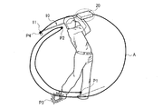
図1は、計測物体例えば運動器具であるゴルフクラブ10のクラブヘッド11のスイング軌跡Aを示している。スイング軌道Aは、スイング起動位置P1、トップ位置P2、インパクト位置P3及びフォロースルートップ位置P4を含んでいる。
1. Motion Analysis Method FIG. 1 shows a swing locus A of a
図2(A)(B)は、本実施形態に用いられるセンサーユニット20(20A,20B)が装着されたゴルフクラブ10と、ゴルフクラブ10の保持具例えば充電器30(30A,30B)を示している。充電器30(30A,30B)は、センサーユニット20(20A,20B)に内蔵されるセンサーに給電する二次電池を充電する。
2A and 2B show the
図2(A)は、ヘッドセンサーユニット20Aがクラブヘッド11に装着されたゴルフクラブ10Aを模式的に示している。充電器30Aは、接地型であり、クラブヘッド11を静止状態に保持して、後述する接点を介してヘッドセンサーユニット20A内の二次電池を充電することができる。
FIG. 2A schematically shows a
図2(B)は、シャフトセンサーユニット20Bがクラブシャフト12に装着されたゴルフクラブ10Bを模式的に示している。充電器30Bは、スタンド型であり、クラブシャフト12を静止状態に保持して、後述する接点を介してヘッドセンサーユニット20B内の二次電池を充電することができる。
FIG. 2B schematically shows a
ここで、図2(A)(B)に示すセンサーユニット20は、例えば三軸検出が可能な加速度センサーを内蔵している。センサーユニット20は三軸検出が可能な角速度センサーを内蔵することもできる。このセンサーユニット20を用いてゴルフクラブ10の運動を解析する方法について、図3〜図6を参照して説明する。なお、以下の実施形態は図2(A)のようにセンサーが装着されたクラブヘッド11の軌道を解析する例である。図2(B)のようにセンサー位置(シャフト)と求める軌道位置(クラブヘッド)とが異なる場合でも、ゴルフクラブ10の角度が角速度センサーから取得され、センサー位置が加速度センサーから取得されれば、センサー位置から一定の距離にあるクラブヘッド11の位置などを追跡することができる。
Here, the
図3のスタート時には、ゴルフクラブ10は図2(A)(B)に示す充電器30(30A,30B)に装着され静止状態である。このとき、センサーユニット20(20A,20B)は既知の始点P0(第1の位置)にあり、速度及び角速度は共に零である。これらが、始点P0(第1の位置)での既知のデータである。
At the start of FIG. 3, the
図3のステップS1では、ゴルフクラブ10が充電器30に装着されている静止状態でのセンサー出力(第1出力データ)を取得する。つまり、図4のスタート時t0から、静止状態にてセンサー出力データ(第1出力データ)をサンプリングして取得する。図3のステップS2では、ゴルフクラブ10が充電器30から離脱されたか否かが監視される。ゴルフクラブ10が充電器30から離脱されたことが取得されると(図3のステップS2での判断がYES)、ステップ3に移行してゴルフクラブ10が充電器30から離脱後のセンサー出力が取得されて、運動解析のための計測が開始される。つまり、図4の時刻t0〜t1までの第1期間T1にて静止状態でのセンサー出力データがサンプリングされ、時刻t1以降ではゴルフクラブ10が充電器30から離脱された以降のセンサー出力データがサンプリングされる。
In step S <b> 1 of FIG. 3, sensor output (first output data) in a stationary state in which the
図3のステップS4では、ゴルフクラブ10が充電器30に戻されたか否かが監視される。図3のステップS4での判断がNOであればステップS3での計測が継続される。ゴルフクラブ10が充電器30に装着されたことが取得されると(ステップS4での判断がYES)、ゴルフクラブ10が充電器30に装着され後のセンサー出力(第2出力データ)が取得された後に、計測が終了される(ステップS5)。
In step S4 of FIG. 3, it is monitored whether or not the
つまり、図4の時刻t1〜t2までの第2期間T1にてゴルフクラブ10が充電器30から離脱された以降のセンサー出力データがサンプリングされ、時刻t2〜t3までの第3期間T3ではゴルフクラブ10が充電器30に戻された以降のセンサー出力データ(第2出力データ)がサンプリングされる。
That is, sensor output data after the
図3のステップS4の後に、ステップS6での運動解析動作に移行することになる。ただし、ステップ6での運動解析動作は、センサー出力の取得と並行して実施してもよい。 After step S4 in FIG. 3, the process proceeds to the motion analysis operation in step S6. However, the motion analysis operation in step 6 may be performed in parallel with the acquisition of the sensor output.
ここで、図3のステップS2を実施することにより、図4に示す時刻t1を自動取得することができる。それにより、取得されたセンサー出力が、物体が保持具に保持されて静止した状態の時のデータであるか、その後の計測対象のデータであるかを明確に区別することができる。 Here, by performing step S2 of FIG. 3, the time t1 shown in FIG. 4 can be automatically acquired. Thereby, it is possible to clearly distinguish whether the acquired sensor output is data when the object is held by the holder and is stationary, or data to be measured thereafter.
また、図4に示す第1期間T1(t0〜t1)でのセンサー出力(第1出力データ)は、始点P0を特定するに足る情報量であればよく、第1期間T1中に取得されたサンプリングデータの全てを記憶する必要はない。始点P0を特定するために、一つのサンプリングデータか、あるいは平均値化するために複数のサンプリングデータが記憶されていればよい。よって、センサー出力を記憶する記憶部での記憶容量を少なくすることができる。また、時刻t1を取得することで、例えば加速度データを時間積分して速度、位置情報を得るためのデータ処理開始位置(時刻)を知ることができる。計測開始を例えば開始音などで告知すると、運動器具を操作する者の運動の自由度が奪われ、開始時期の告知を待つことから緊張感を付与するなどの弊害がある。その点、本実施形態ではそのような弊害を解消できる利点もある。 Further, the sensor output (first output data) in the first period T1 (t0 to t1) shown in FIG. 4 may be an information amount sufficient to specify the start point P0, and is acquired during the first period T1. It is not necessary to store all of the sampling data. In order to specify the starting point P0, one sampling data or a plurality of sampling data may be stored for averaging. Therefore, the storage capacity in the storage unit that stores the sensor output can be reduced. Also, by acquiring the time t1, for example, it is possible to know the data processing start position (time) for obtaining speed and position information by integrating the acceleration data over time. If the start of measurement is notified with, for example, a start sound, the degree of freedom of movement of the person who operates the exercise equipment is lost, and there is an adverse effect such as giving a sense of tension because waiting for notification of the start time. In this respect, the present embodiment also has an advantage that such an adverse effect can be eliminated.
同様に、図3のステップS4を実施することにより、図4に示す時刻t2を自動取得することができる。それにより、取得されたセンサー出力(第2出力データ)が、物体が保持具に再び保持されて静止した状態の時のデータであるか、それ以前の計測対象のデータであるかを明確に区別することができる。また、図4に示す第3期間T3(t2〜t3)でのセンサー出力(第1出力データ)は、ゴルフクラブ10が充電器30に戻された時の終点を特定するに足る情報量であればよく、第1期間T3を過度に長く設定する必要はない。このことによっても、センサー出力を記憶する記憶部での記憶容量を少なくすることができる。
Similarly, by performing step S4 of FIG. 3, the time t2 shown in FIG. 4 can be automatically acquired. Thereby, it is clearly distinguished whether the acquired sensor output (second output data) is the data when the object is held again by the holder and is stationary or the data of the measurement target before that. can do. Further, the sensor output (first output data) in the third period T3 (t2 to t3) shown in FIG. 4 is an information amount sufficient to specify the end point when the
図5は、充電器30(30A,30B)を始点P0及び終点P5としたスイング軌跡A1の一例を模式的に示している。なお、図5に示す軌跡A1には、図1に示すスイング軌跡Aに追加して、始点P0からスイング起動位置P1に至る軌跡A2と、フォロースルートップ位置P4から例えば図1に示すスイング軌跡Aの一部を帰路として辿った後に分岐されて終点P5に至る軌跡A3が追加されている。なお、実際の計測では、始点P0及び終点P5以外の各位置や軌跡は様々である。 FIG. 5 schematically shows an example of a swing locus A1 having the charger 30 (30A, 30B) as the start point P0 and the end point P5. In addition to the swing trajectory A shown in FIG. 1, the trajectory A1 shown in FIG. 5 includes a trajectory A2 from the start point P0 to the swing activation position P1, and a swing trajectory A shown in FIG. 1 from the follow-through top position P4. A trajectory A3 that is branched after tracing a part of the return path to the end point P5 is added. In actual measurement, each position and locus other than the start point P0 and the end point P5 are various.
上述した通り、加速度センサーが検出する加速度値a(t)に対して、それぞれ時間積分処理を行うことで、被測定物であるゴルフクラブ10の例えばクラブヘッド11の速度V(t)及び位置p(t)を算出することができる。
As described above, for example, the velocity V (t) and position p of the
この際、センサーユニット20(20A,20B)は既知の始点P0(第1の位置)にあり、速度及び角速度は共に零である。始点P0(第1の位置)についてこれらの既知のデータを用いて、始点P0(第1の位置)でのセンサー出力(第1出力データ)及びその演算結果が初期化される。 At this time, the sensor unit 20 (20A, 20B) is at a known starting point P0 (first position), and both the velocity and the angular velocity are zero. Using these known data for the start point P0 (first position), the sensor output (first output data) at the start point P0 (first position) and the calculation result thereof are initialized.
しかし、図5に示す軌跡A1を移動中の実際のセンサーユニット20中の加速度センサーの出力データX(t),Y(t),Z(t)には誤差E(t)が含まれている。よって、センサーユニット20中の加速度センサーの出力データX(t),Y(t),Z(t)に対して時間積分を二回実施して得られる位置p(t)は、始点P0での位置で初期化して一致させても、図5に示す実際の位置P1〜P5に対して演算結果では位置P1’〜P5’にずれてしまう。
However, error data E (t) is included in the output data X (t), Y (t), and Z (t) of the acceleration sensor in the
一方、終点(第2の位置)P5でも位置は既知であり、終点P5での速度及び角速度は共に零(既知)である。そこで、終点(第2の位置)P5についてこれらの既知のデータを用いて、出力データX(t),Y(t),Z(t)に含まれる誤差E(t)の時間積分に起因した累積誤差を解消するための補正を行うことができる。 On the other hand, the position is also known at the end point (second position) P5, and the velocity and the angular velocity at the end point P5 are both zero (known). Therefore, using these known data for the end point (second position) P5, it is caused by the time integration of the error E (t) included in the output data X (t), Y (t), Z (t). Correction to eliminate the accumulated error can be performed.
図6は、本来の終点P5(=P0)と、終点P5でのセンサーからの第2出力データである出力データX(t),Y(t),Z(t)に基づいて演算された終点P5’とで、直交三軸のX,Y,Z成分の誤差ΔX,ΔY,ΔZを示している。図6では、終点P5(=P0)は、X=0、Y=0、Z=0と初期化されている。ここで、図4に示すように、時刻t1で始点P0をスタートしたゴルフクラブ10は時刻t2に終点P5に到達している。従って、図5に示すゴルフクラブ10の軌跡A1において、単位時間Δt当たりのX,Y,Z方向の各誤差成分はΔX/(t2−t1)、ΔY/(t2−t1)、ΔZ/(t2−t1)となる。
FIG. 6 shows the end point calculated based on the original end point P5 (= P0) and the output data X (t), Y (t), Z (t) as the second output data from the sensor at the end point P5. P5 ′ indicates errors ΔX, ΔY, ΔZ of the three orthogonal X, Y, Z components. In FIG. 6, the end point P5 (= P0) is initialized as X = 0, Y = 0, and Z = 0. Here, as shown in FIG. 4, the
つまり、単位時間Δtが経過するごとにX,Y,Z方向の各誤差成分ΔX/(t2−t1)、ΔY/(t2−t1)、ΔZ/(t2−t1)が累積している。よって、例えば位置Pから位置P1’にn×Δt後に到達したのであれば、位置P1’のX,Y,X成分からX,Y,Z方向の各誤差ΔX/(t2−t1)、ΔY/(t2−t1)、ΔZ/(t2−t1)をそれぞれn倍した累積誤差を減算すれば、正しい位置P1を求めることができる。同様にして、センサーからの出力データX(t),Y(t),Z(t)に基づいて演算された位置P2’〜P5’を正しい位置P2〜P5に補正することができる。ただし、既知の位置P0,P5での既知のデータを用いてセンサー出力の演算結果を補正する手法については、これに限定されるものではない。 That is, each time the unit time Δt elapses, error components ΔX / (t2−t1), ΔY / (t2−t1), and ΔZ / (t2−t1) in the X, Y, and Z directions are accumulated. Therefore, for example, if the position P1 ′ is reached after n × Δt from the position P, the errors XX / (t2−t1) and ΔY / in the X, Y, and Z directions from the X, Y, and X components of the position P1 ′. The correct position P1 can be obtained by subtracting the accumulated errors obtained by multiplying (t2−t1) and ΔZ / (t2−t1) by n. Similarly, the positions P2 'to P5' calculated based on the output data X (t), Y (t) and Z (t) from the sensor can be corrected to the correct positions P2 to P5. However, the method for correcting the calculation result of the sensor output using the known data at the known positions P0 and P5 is not limited to this.
ここで、上述した実施形態はゴルフクラブ10の位置を解析するものであったが、センサーからの出力データの時間積分を1回だけして得られる速度V(t)についても、第1の位置P1と第2の位置P5にて速度が零となる既知のデータを用いて同様に補正することができる。角速度センサーの出力データについては、第1の位置P1と第2の位置P5にて各軸廻りの回転角度についての既知のデータを用いて同様に補正することができる。
Here, the embodiment described above is for analyzing the position of the
なお、上述した実施形態では、第1の位置P0と第2の位置P5が等しいものであったが、それに限定されない。第2の位置は、物体が既知の通過点を通過する時のセンサーの位置であってもよく、例えば、図3及び図5に示すインパクト位置P3は、ゴルフボールがティーアップされた位置として既知であるので、インパクト位置P3を少なくとも一つの第2の位置として利用することができる。好ましくは、第1の位置P0と2つの第2の位置P3,P5での既知のデータを利用してゴルフクラブ10の運動を解析することができる。
In the above-described embodiment, the first position P0 and the second position P5 are equal. However, the present invention is not limited to this. The second position may be the position of the sensor when the object passes through a known passing point. For example, the impact position P3 shown in FIGS. 3 and 5 is known as the position where the golf ball is teeed up. Therefore, the impact position P3 can be used as at least one second position. Preferably, the motion of the
2.運動解析装置
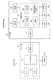
図7は、本実施形態の運動解析装置の構成を示す図である。実施形態の運動解析装置40は、1又は複数のセンサーユニット20とホスト端末50を含んで構成され、対象物体10の運動を解析する。センサーユニット20は、センサー部100と二次電池130とを含むことができる。センサー部100とホスト端末50は無線接続されていてもよいし、有線接続されていてもよい。
2. Motion Analysis Device FIG. 7 is a diagram showing a configuration of the motion analysis device of the present embodiment. The motion analysis apparatus 40 according to the embodiment includes one or a plurality of
センサーユニット20は、図2(A)または図2(B)に示すように、運動解析の対象物体10に取り付けられ、所与の物理量を検出する処理を行う。本実施形態では、センサーは、図8にも示すように、少なくとも一つ例えば複数のセンサー102x〜102z及び104x〜104z、データ処理部110、通信部120を含んで構成されている。
As shown in FIG. 2A or 2B, the
ここで、センサーは所与の物理量を検出し、検出した物理量(例えば、加速度、角速度、速度、角加速度など)の大きさに応じた信号(データ)を出力するセンサーである。本実施形態では、X軸、Y軸、Z軸方向の加速度を検出する三軸加速度センサー102x〜102z(慣性センサーの一例)と、X軸、Y軸、Z軸方向の角速度を検出する三軸ジャイロセンサー(角速度センサー、慣性センサーの一例)104x〜104zとからなる6軸モーションセンサーを備えている。
Here, the sensor is a sensor that detects a given physical quantity and outputs a signal (data) corresponding to the magnitude of the detected physical quantity (for example, acceleration, angular velocity, speed, angular acceleration, etc.). In the present embodiment,
データ処理部110は、各センサー102x〜102z及び104x〜104zの出力データの同期を取り、当該データを時刻情報などと組合せたパケットにして通信部120に出力する処理を行う。さらに、データ処理部110は、センサー102x〜102z及び104x〜104zのバイアス補正や温度補正の処理を行うようにしてもよい。なお、バイアス補正や温度補正の機能をセンサー自体に組み込んでもよい。
The
通信部120は、データ処理部110から受け取ったパケットデータをホスト端末50に送信する処理を行う。
The
ホスト端末50は、処理部(CPU)200、通信部210、操作部220、ROM230、RAM240、不揮発性メモリー250、表示部260を含んで構成されている。
The
通信部210は、センサー部100から送信されたデータを受信し、処理部200に送る処理を行う。
The
操作部220は、ユーザーからの操作データを取得し、処理部200に送る処理を行う。操作部220は、例えば、タッチパネル型ディスプレイ、ボタン、キー、マイクなどである。
The
ROM230は、処理部200が各種の計算処理や制御処理を行うためのプログラムや、アプリケーション機能を実現するための各種プログラムやデータ等を記憶している。
The
RAM240は、処理部200の作業領域として用いられ、ROM230から読み出されたプログラムやデータ、操作部220から入力されたデータ、処理部200が各種プログラムに従って実行した演算結果等を一時的に記憶する記憶部である。
The
なお、本実施形態では特に、第1の位置P0や第2の位置P3,P5についての既知のデータを、ROM230またはRAM240に記憶しておくことができる。
In the present embodiment, in particular, known data about the first position P0 and the second positions P3 and P5 can be stored in the
不揮発性メモリー250は、処理部200の処理により生成されたデータのうち、長期的な保存が必要なデータを記録する記憶部である。
The
表示部260は、処理部200の処理結果を文字やグラフ、その他の画像として表示するものである。表示部260は、例えば、CRT、LCD、タッチパネル型ディスプレイ、HMD(ヘッドマウントディスプレイ)などである。なお、1つのタッチパネル型ディスプレイで操作部220と表示部260の機能を実現するようにしてもよい。
The
処理部200は、ROM230に記憶されているプログラムに従って、センサー部100から通信部210を介して受信したデータに対する各種の計算処理や、各種の制御処理(表示部260に対する表示制御等)を行う。
The
特に、本実施形態では、処理部200は、データ取得部202、演算部204、データ補正部206、運動解析情報生成部208として機能する。
In particular, in the present embodiment, the
データ取得部202は、センサー102x〜102z及び104x〜104zの検出対象である物体10の物理量のm階時間積分値(mは自然数)の真値が既知である図4の第1,第3期間T1,T3と、運動解析の対象である第2期間T2とを含む期間において、センサー部100の出力データを取得する処理を行う。取得したデータは例えばRAM240に記憶される。
The
演算部204は、図4の第1期間T1に取得された位置P0についての既知のデータで初期化して、センサー部100の出力データをm階時間積分する演算を実施する。演算部204がセンサー部100の出力データを例えば2階時間積分すると、図5に示す位置P0,P1’〜P5’が得られる。
The
データ補正部206は、演算部204での演算結果を、図4の第3期間T3にて取得された位置P5についての既知のデータに基づいて補正する。これにより、図5に示す位置P1’〜P5’は、正しい位置P1〜P5に補正される。
The
運動解析情報生成部208は、データ補正部206からの補正データに基づいて、対象物体10の運動を解析するための情報(以下、「運動解析情報」という)を生成する処理を行う。生成した運動解析情報は、文字、グラフ、図などで表示部260に表示させてもよいし、ホスト端末50の外部に出力してもよい。なお、上述した演算部204、データ補正部206及び運動解析情報生成部208は、運動解析部の一例である。
The motion analysis
3.充電器及び運動器具
次に、本実施形態の運動解析方法及び装置に好適に用いられる充電器30及び測定対象の運動器具10について説明する。
3. Next, the
図9は、図2(B)に示す充電器30及び測定対象の運動器具(ゴルフクラブ)10Bの基本的構成例を示している。保持具として機能する充電器30は、接地部31と、接地部31から上方に延びるシャフト保持部32と、例えば接地部31に設けられた充電回路33と、シャフト保持部32に設けられた2つの充電端子34,35を有している。ゴルフクラブ10Bは、充電器30の充電端子34,35に接触する被充電端子13,14を、クラブシャフト12に有する。なお、ゴルフクラブ10Bに設けられるセンサーユニット20は図9では図示が省略されている。
FIG. 9 shows a basic configuration example of the
図10は、図9に示すゴルフクラブ10B及び充電器30を用いて、図3のステップS3及びステップS4にて充電器30にゴルフクラブ10Bが装着されたか否かの検出を行う構成例を示している。
FIG. 10 shows a configuration example for detecting whether or not the
ここで、ゴルフクラブ10Bのセンサーユニット20には、被充電端子13,14に接続された二次電池130が設けられている。センサーユニット20には、図7に示す構成要素に加えて、充電電圧検出回路16と、充電制御回路17と、センサー制御回路18等を設けることができる。二次電池130の充電電圧は充電電圧検出回路16にて検出され、その検出結果に基づいて充電制御回路17が二次電池130への充電を制御する。センサー制御回路18は、二次電池130から電力が供給され、図7に示すセンサー102x〜102z及び104x〜104zを制御する。一方、充電器30には、例えば+側の充電端子34に接続された電池検出回路36を設けることができる。
Here, the
充電器30及びゴルフクラブ10Bは、ゴルフクラブ10Bが充電器30に装着されているか非装着かを検出するスイッチSW1を、例えばゴルフクラブ10Bに設けられた被充電端子13(第1接点)と充電器30に設けられた充電端子34(第2接点)により構成することができる。
The
被充電端子13(第1接点)と充電端子34(第2接点)の接触/非接触は、例えば充電器30に設けられた電池検出回路36にて検出される。電池検出回路36は、被充電端子13(第1接点)と充電端子34(第2接点)の接触/非接触に伴って変動する電流、電圧、抵抗値等から、二次電池130が接続されているか否かを判別することができる。スイッチSW1と電池検出回路36は、装着/非装着検出部の一例である。
Contact / non-contact between the charged terminal 13 (first contact) and the charging terminal 34 (second contact) is detected by, for example, a
つまり、電池検出回路36の出力は、ゴルフクラブ10Bの装着/非装着情報となる。この情報が図7に示すホスト端末50にて取得されることで、図3のステップS3及びステップS4にて充電器30にゴルフクラブ10Bが装着されたか否かの検出することができる。それにより、図7に示す運動解析部204,206,208は、第1接点13が第2接点34より離脱される時の信号や、その後第1接点13が第2接点34に接触される時の信号を取得して、ゴルフクラブ10Bの運動を解析することができる。
In other words, the output of the
これらの装着/非装着検出信号は、センサー出力と共にデータとしてホスト端末50に送信されてもよいし、センサー出力とは別に有線または無線でホスト端末50に送信されてもよい。
These mounting / non-mounting detection signals may be transmitted to the
あるいは、図10に示す電池検出回路36をゴルフクラブ10B側に設け、ゴルフクラブ10B側から装着/非装着検出信号を無線でホスト端末50に送信してもよい。なお、図10に示す装着/非装着検出方式は、図2(A)に示すゴルフクラブ10Aにも適用することができる。
Alternatively, the
図11及び図12は、例えば図2(A)に示すゴルフクラブ10Aに適用できる図10とは異なる装着/非装着検出方式を示している。図11に示すように、充電器30がクラブヘッド11を保持する位置に、プッシュボタン63が突出形成されている。プッシュボタン63は、クラブヘッド11が充電器30に装着されることで押下される。
11 and 12 show a mounting / non-mounting detection method different from that shown in FIG. 10 that can be applied to the
図12に示すように、充電器30には充電端子34,35に加えて、プッシュボタン63を含むスイッチSW2が設けられている。スイッチSW2は、2つの固定接点60,61と、プッシュボタン63により固定接点60,61間をショートさせる可動接点62を含んでいる。
As shown in FIG. 12, the
ここで、スイッチSW2が閉状態(装着状態)と開状態(非装着状態)とで、スイッチSW2からの出力を変動させることができる。よって、スイッチSW2からの信号を装着/非装着検出信号として利用することができる。この場合も、装着/非装着検出信号は、センサー出力と共にデータとしてホスト端末50に送信されてもよいし、センサー出力とは別に有線または無線でホスト端末50に送信されてもよい。
Here, the output from the switch SW2 can be varied depending on whether the switch SW2 is in the closed state (attached state) or in the open state (non-attached state). Therefore, the signal from the switch SW2 can be used as a mounting / non-mounting detection signal. Also in this case, the attachment / non-attachment detection signal may be transmitted as data to the
なお、上記のように本実施形態について詳細に説明したが、本発明の新規事項および効果から実体的に逸脱しない多くの変形が可能であることは当業者には容易に理解できるであろう。従って、このような変形例はすべて本発明の範囲に含まれるものとする。例えば、本発明の測定対象物体は、好適にはゴルフクラブ、テニスラケット等の運動器具に適用することができるが、これに限定されない。 Although the present embodiment has been described in detail as described above, it will be easily understood by those skilled in the art that many modifications can be made without departing from the novel matters and effects of the present invention. Accordingly, all such modifications are intended to be included in the scope of the present invention. For example, the measurement target object of the present invention can be preferably applied to an exercise apparatus such as a golf club or a tennis racket, but is not limited thereto.
10,10A,10B 測定対象物体、13 第1接点、20,20A,20B センサーユニット、30 保持具(充電器)、34 第2接点、40 運動解析装置、50 ホスト端末、100 センサー部、102x〜102z,104x〜104z センサー、130 二次電池、204,206,208 運動解析部、SW1,SW2 スイッチ 10, 10A, 10B Measurement object, 13 First contact, 20, 20A, 20B Sensor unit, 30 Holder (charger), 34 Second contact, 40 Motion analysis device, 50 Host terminal, 100 Sensor unit, 102x˜ 102z, 104x to 104z sensor, 130 secondary battery, 204, 206, 208 motion analysis unit, SW1, SW2 switch
Claims (7)
前記運動器具を前記保持具より離脱し、前記センサーの出力を用いて前記運動器具を用いた運動の解析を行う工程と、を含み、
前記運動の解析を行う工程において、前記第1の位置に設定された時の前記センサーの第1出力データと、前記運動器具が前記保持具より離脱された後に既知の通過点を通過する第2の位置に前記センサーが設定された時の前記センサーの第2出力データと、を含む前記センサーの出力を取得し、前記第1出力データ及び前記第2出力データを用いて、前記センサーの誤差を補正することを特徴とする運動解析方法。 Holding an exercise device with a sensor attached to a holder and setting the sensor to a first position;
Detaching the exercise apparatus from the holder, and analyzing the movement using the exercise apparatus using the output of the sensor,
In the step of analyzing the movement, the first output data of the sensor when set to the first position, and a first passing point after passing through the known passing point after the exercise apparatus is detached from the holder. Output of the sensor including the second output data of the sensor when the sensor is set at position 2, and using the first output data and the second output data, an error of the sensor is obtained. A motion analysis method characterized by correcting the motion.
前記運動の解析を行う工程は、前記運動器具が前記保持具より離脱される時の信号を取得して、前記運動器具の運動の計測を開始することを特徴とする運動解析方法。 In claim 1 ,
The motion analysis method is characterized in that in the step of analyzing the exercise, a signal when the exercise device is detached from the holder is acquired, and measurement of the exercise device is started.
前記運動器具が前記保持具より離脱された後に前記保持具に装着される時の信号を取得して、前記運動器具の運動の計測を停止することを特徴とする運動解析方法。 In claim 2 ,
A motion analysis method comprising: obtaining a signal when the exercise equipment is attached to the holder after being detached from the holder, and stopping the measurement of the movement of the exercise equipment.
前記運動器具を保持して、前記センサーを第1の位置に設定する保持具と、
前記センサーの出力を用いて前記運動器具を用いた運動の解析を行う運動解析部と、を
含み、
前記運動解析部は、前記第1の位置に設定された前記センサーの第1出力データと、前記運動器具が前記保持具より離脱された後に既知の通過点を通過する第2の位置に前記センサーが設定された時の前記センサーの第2出力データと、を含む前記センサーの出力を取得し、前記第1出力データ及び前記第2出力データを用いて、前記センサーの誤差を補正することを特徴とする運動解析装置。 A sensor that is attached to an exercise device and detects a physical quantity;
A holder for holding the exercise apparatus and setting the sensor in a first position;
A motion analysis unit that performs motion analysis using the exercise apparatus using the output of the sensor,
The motion analysis unit has the first output data of the sensor set at the first position and the second position passing through a known passing point after the exercise equipment is detached from the holding tool. The sensor output including the second output data of the sensor when the sensor is set, and correcting the error of the sensor using the first output data and the second output data. Characteristic motion analysis device.
前記保持具は、前記運動器具を保持した際に前記センサーに給電することを特徴とする運動解析装置。 In claim 4 ,
The holding analysis device supplies power to the sensor when holding the exercise equipment.
前記保持具及び前記運動器具の少なくとも一方は、前記運動器具が前記保持具に保持されているか否かを検出するスイッチを含み、
前記運動解析部は、前記スイッチにより前記運動器具が前記保持具から離脱される時の信号を取得して、前記運動器具の運動の計測を開始することを特徴とする運動解析装置。 In claim 5 ,
At least one of the holder and the exercise device includes a switch that detects whether the exercise device is held by the holder,
The motion analysis apparatus is characterized in that the motion analysis unit acquires a signal when the exercise device is detached from the holder by the switch, and starts measuring the motion of the exercise device.
前記スイッチは、前記運動器具に設けられた第1接点と前記保持具に設けられた第2接点とを含むことを特徴とする運動解析装置。 In claim 6 ,
The motion analysis apparatus according to claim 1, wherein the switch includes a first contact provided on the exercise equipment and a second contact provided on the holder.
Priority Applications (3)
| Application Number | Priority Date | Filing Date | Title |
|---|---|---|---|
| JP2011275958A JP5915148B2 (en) | 2011-12-16 | 2011-12-16 | Motion analysis method and motion analysis apparatus |
| US13/709,563 US20130173212A1 (en) | 2011-12-16 | 2012-12-10 | Motion analysis method and motion analysis apparatus |
| CN2012105441533A CN103157265A (en) | 2011-12-16 | 2012-12-14 | Motion analysis method and motion analysis apparatus |
Applications Claiming Priority (1)
| Application Number | Priority Date | Filing Date | Title |
|---|---|---|---|
| JP2011275958A JP5915148B2 (en) | 2011-12-16 | 2011-12-16 | Motion analysis method and motion analysis apparatus |
Publications (3)
| Publication Number | Publication Date |
|---|---|
| JP2013125024A JP2013125024A (en) | 2013-06-24 |
| JP2013125024A5 JP2013125024A5 (en) | 2015-02-05 |
| JP5915148B2 true JP5915148B2 (en) | 2016-05-11 |
Family
ID=48581113
Family Applications (1)
| Application Number | Title | Priority Date | Filing Date |
|---|---|---|---|
| JP2011275958A Expired - Fee Related JP5915148B2 (en) | 2011-12-16 | 2011-12-16 | Motion analysis method and motion analysis apparatus |
Country Status (3)
| Country | Link |
|---|---|
| US (1) | US20130173212A1 (en) |
| JP (1) | JP5915148B2 (en) |
| CN (1) | CN103157265A (en) |
Families Citing this family (34)
| Publication number | Priority date | Publication date | Assignee | Title |
|---|---|---|---|---|
| US10241127B2 (en) * | 2009-07-30 | 2019-03-26 | Here Global B.V. | Method, apparatus and computer program product for collecting activity data via a removable apparatus |
| US9396385B2 (en) | 2010-08-26 | 2016-07-19 | Blast Motion Inc. | Integrated sensor and video motion analysis method |
| US9418705B2 (en) | 2010-08-26 | 2016-08-16 | Blast Motion Inc. | Sensor and media event detection system |
| US9940508B2 (en) | 2010-08-26 | 2018-04-10 | Blast Motion Inc. | Event detection, confirmation and publication system that integrates sensor data and social media |
| US9261526B2 (en) | 2010-08-26 | 2016-02-16 | Blast Motion Inc. | Fitting system for sporting equipment |
| US9406336B2 (en) | 2010-08-26 | 2016-08-02 | Blast Motion Inc. | Multi-sensor event detection system |
| US9626554B2 (en) | 2010-08-26 | 2017-04-18 | Blast Motion Inc. | Motion capture system that combines sensors with different measurement ranges |
| US9619891B2 (en) | 2010-08-26 | 2017-04-11 | Blast Motion Inc. | Event analysis and tagging system |
| US9076041B2 (en) | 2010-08-26 | 2015-07-07 | Blast Motion Inc. | Motion event recognition and video synchronization system and method |
| US9607652B2 (en) | 2010-08-26 | 2017-03-28 | Blast Motion Inc. | Multi-sensor event detection and tagging system |
| US9320957B2 (en) | 2010-08-26 | 2016-04-26 | Blast Motion Inc. | Wireless and visual hybrid motion capture system |
| US9247212B2 (en) | 2010-08-26 | 2016-01-26 | Blast Motion Inc. | Intelligent motion capture element |
| US9646209B2 (en) | 2010-08-26 | 2017-05-09 | Blast Motion Inc. | Sensor and media event detection and tagging system |
| US9039527B2 (en) | 2010-08-26 | 2015-05-26 | Blast Motion Inc. | Broadcasting method for broadcasting images with augmented motion data |
| US9604142B2 (en) | 2010-08-26 | 2017-03-28 | Blast Motion Inc. | Portable wireless mobile device motion capture data mining system and method |
| US9401178B2 (en) | 2010-08-26 | 2016-07-26 | Blast Motion Inc. | Event analysis system |
| US9235765B2 (en) | 2010-08-26 | 2016-01-12 | Blast Motion Inc. | Video and motion event integration system |
| US8941723B2 (en) | 2010-08-26 | 2015-01-27 | Blast Motion Inc. | Portable wireless mobile device motion capture and analysis system and method |
| JP2015100478A (en) * | 2013-11-22 | 2015-06-04 | セイコーエプソン株式会社 | Motion analysis method, motion analysis display method, motion analysis device, and motion analysis program |
| JP2015156882A (en) * | 2014-02-21 | 2015-09-03 | セイコーエプソン株式会社 | Motion analysis device and motion analysis system |
| JP2016033474A (en) * | 2014-07-31 | 2016-03-10 | セイコーエプソン株式会社 | Position calculation method and position calculation device |
| JP2016032611A (en) * | 2014-07-31 | 2016-03-10 | セイコーエプソン株式会社 | Exercise analysis device, exercise analysis system, exercise analysis method and exercise analysis program |
| CN105387871A (en) * | 2014-08-26 | 2016-03-09 | 精工爱普生株式会社 | Motion analysis device, motion analysis method and motion analysis system |
| US10124230B2 (en) | 2016-07-19 | 2018-11-13 | Blast Motion Inc. | Swing analysis method using a sweet spot trajectory |
| US11577142B2 (en) | 2015-07-16 | 2023-02-14 | Blast Motion Inc. | Swing analysis system that calculates a rotational profile |
| US11565163B2 (en) | 2015-07-16 | 2023-01-31 | Blast Motion Inc. | Equipment fitting system that compares swing metrics |
| US10974121B2 (en) | 2015-07-16 | 2021-04-13 | Blast Motion Inc. | Swing quality measurement system |
| US9694267B1 (en) | 2016-07-19 | 2017-07-04 | Blast Motion Inc. | Swing analysis method using a swing plane reference frame |
| US10265602B2 (en) | 2016-03-03 | 2019-04-23 | Blast Motion Inc. | Aiming feedback system with inertial sensors |
| US10786728B2 (en) | 2017-05-23 | 2020-09-29 | Blast Motion Inc. | Motion mirroring system that incorporates virtual environment constraints |
| EP3632512B1 (en) * | 2017-06-02 | 2023-03-08 | Sony Group Corporation | Information processing device, information processing method, and program |
| US11556879B1 (en) * | 2017-06-12 | 2023-01-17 | Amazon Technologies, Inc. | Motion data driven performance evaluation and training |
| CN111954491A (en) | 2018-04-17 | 2020-11-17 | 索尼公司 | Program, information processing apparatus, and information processing method |
| CN115003392A (en) * | 2020-01-21 | 2022-09-02 | 涛普高尔夫瑞典公司 | Trajectory extrapolation and start point determination for in-flight tracked objects |
Family Cites Families (14)
| Publication number | Priority date | Publication date | Assignee | Title |
|---|---|---|---|---|
| US5028909A (en) * | 1990-04-16 | 1991-07-02 | Miller Robert A | Golf bag alarm |
| JPH0763561A (en) * | 1993-08-24 | 1995-03-10 | Kawasaki Steel Corp | Azimuth measuring device and method for correcting its drift |
| CN2499077Y (en) * | 2000-08-10 | 2002-07-10 | 宋战美 | Analogue system measuring device for golf sport |
| KR20070095407A (en) * | 2005-01-26 | 2007-09-28 | 벤틀리 키네틱스 인코포레이티드 | Method and system for athletic motion analysis and instruction |
| US8226494B2 (en) * | 2005-07-08 | 2012-07-24 | Suunto Oy | Golf device and method |
| EP2281668B1 (en) * | 2005-09-30 | 2013-04-17 | iRobot Corporation | Companion robot for personal interaction |
| JP2008073210A (en) * | 2006-09-21 | 2008-04-03 | Seiko Epson Corp | Golf club and its swing evaluation support apparatus |
| US8398502B2 (en) * | 2007-11-27 | 2013-03-19 | Mugen Inc. | Hitting position detecting device, hitting position detecting method, and method of manufacturing hitting position detecting device |
| US20090326688A1 (en) * | 2008-02-01 | 2009-12-31 | Nike, Inc. | Systems and Methods for Fitting Golfers with Golf Clubs |
| CN201286963Y (en) * | 2008-09-16 | 2009-08-12 | 景风科技股份有限公司 | Ball-rod wireless sensing device and system thereof |
| US8062145B1 (en) * | 2009-06-04 | 2011-11-22 | Callaway Golf Company | Device to measure the motion of a golf club |
| CN102574012A (en) * | 2009-09-25 | 2012-07-11 | 富士通株式会社 | Locus generation program and locus generation device |
| US8882606B2 (en) * | 2010-01-28 | 2014-11-11 | Nike, Inc. | Golf swing data gathering method and system |
| CN101927084B (en) * | 2010-08-27 | 2012-07-04 | 北方工业大学 | Golf practice club |
-
2011
- 2011-12-16 JP JP2011275958A patent/JP5915148B2/en not_active Expired - Fee Related
-
2012
- 2012-12-10 US US13/709,563 patent/US20130173212A1/en not_active Abandoned
- 2012-12-14 CN CN2012105441533A patent/CN103157265A/en active Pending
Also Published As
| Publication number | Publication date |
|---|---|
| CN103157265A (en) | 2013-06-19 |
| US20130173212A1 (en) | 2013-07-04 |
| JP2013125024A (en) | 2013-06-24 |
Similar Documents
| Publication | Publication Date | Title |
|---|---|---|
| JP5915148B2 (en) | Motion analysis method and motion analysis apparatus | |
| JP5948011B2 (en) | Motion analysis device | |
| JP5704317B2 (en) | Swing analysis device, swing analysis system, program, and swing analysis method | |
| JP6467766B2 (en) | Motion analysis method, motion analysis apparatus, and motion analysis program | |
| JP6168276B2 (en) | Analysis control device, motion analysis system, program, recording medium, and motion analysis method | |
| JP2015156882A (en) | Motion analysis device and motion analysis system | |
| JP5773144B2 (en) | Motion analysis apparatus, motion analysis system, motion analysis program, and recording medium | |
| TW201501751A (en) | Motion analysis device | |
| JP2013192591A (en) | Motion analysis information collecting apparatus, motion analysis device and motion analysis method | |
| JP7215515B2 (en) | Analysis device, analysis method and program | |
| US20170203187A1 (en) | Presentation method, swing analysis apparatus, swing analysis system, swing analysis program, and recording medium | |
| JP2013202066A (en) | Motion analysis device | |
| US20160089568A1 (en) | Exercise analysis device, exercise analysis system, exercise analysis method, and program | |
| EP3120901A1 (en) | Movement analysis method, movement analysis device, movement analysis system and program | |
| JP2017029516A (en) | Golf swing analysis device | |
| JP2016067409A (en) | Sensor, movement measurement system, and movement measurement method | |
| JP2016067408A (en) | Sensor, arithmetic unit, movement measurement method, movement measurement system, and program | |
| JP6380733B2 (en) | Motion analysis device, motion analysis system, motion analysis method, motion analysis information display method and program | |
| JP6074897B2 (en) | Motion analysis apparatus and motion analysis method | |
| WO2016114126A1 (en) | Detection device, detection system, motion analysis system, recording medium, and analysis method | |
| CN115999139A (en) | Real-time sports action training aid | |
| US20170011652A1 (en) | Motion analysis method, motion analysis apparatus, motion analysis system, and program | |
| KR101672481B1 (en) | Swing posture analyzing system | |
| KR101889617B1 (en) | Golf practice system for swing posture analysis and calibration | |
| US20170004729A1 (en) | Motion analysis method, motion analysis apparatus, motion analysis system, and program |
Legal Events
| Date | Code | Title | Description |
|---|---|---|---|
| A521 | Request for written amendment filed |
Free format text: JAPANESE INTERMEDIATE CODE: A523 Effective date: 20141211 |
|
| A621 | Written request for application examination |
Free format text: JAPANESE INTERMEDIATE CODE: A621 Effective date: 20141211 |
|
| A977 | Report on retrieval |
Free format text: JAPANESE INTERMEDIATE CODE: A971007 Effective date: 20151015 |
|
| A131 | Notification of reasons for refusal |
Free format text: JAPANESE INTERMEDIATE CODE: A131 Effective date: 20151020 |
|
| A521 | Request for written amendment filed |
Free format text: JAPANESE INTERMEDIATE CODE: A523 Effective date: 20151218 |
|
| TRDD | Decision of grant or rejection written | ||
| A01 | Written decision to grant a patent or to grant a registration (utility model) |
Free format text: JAPANESE INTERMEDIATE CODE: A01 Effective date: 20160308 |
|
| A61 | First payment of annual fees (during grant procedure) |
Free format text: JAPANESE INTERMEDIATE CODE: A61 Effective date: 20160321 |
|
| R150 | Certificate of patent or registration of utility model |
Ref document number: 5915148 Country of ref document: JP Free format text: JAPANESE INTERMEDIATE CODE: R150 |
|
| LAPS | Cancellation because of no payment of annual fees |