JP5865902B2 - System and method for intelligent and flexible management and monitoring of computer systems - Google Patents
System and method for intelligent and flexible management and monitoring of computer systems Download PDFInfo
- Publication number
- JP5865902B2 JP5865902B2 JP2013514312A JP2013514312A JP5865902B2 JP 5865902 B2 JP5865902 B2 JP 5865902B2 JP 2013514312 A JP2013514312 A JP 2013514312A JP 2013514312 A JP2013514312 A JP 2013514312A JP 5865902 B2 JP5865902 B2 JP 5865902B2
- Authority
- JP
- Japan
- Prior art keywords
- power
- computer system
- computer
- pcb
- pmc
- Prior art date
- Legal status (The legal status is an assumption and is not a legal conclusion. Google has not performed a legal analysis and makes no representation as to the accuracy of the status listed.)
- Expired - Fee Related
Links
Images


Classifications
-
- G—PHYSICS
- G06—COMPUTING; CALCULATING OR COUNTING
- G06F—ELECTRIC DIGITAL DATA PROCESSING
- G06F11/00—Error detection; Error correction; Monitoring
- G06F11/22—Detection or location of defective computer hardware by testing during standby operation or during idle time, e.g. start-up testing
-
- G—PHYSICS
- G06—COMPUTING; CALCULATING OR COUNTING
- G06F—ELECTRIC DIGITAL DATA PROCESSING
- G06F11/00—Error detection; Error correction; Monitoring
- G06F11/30—Monitoring
- G06F11/3058—Monitoring arrangements for monitoring environmental properties or parameters of the computing system or of the computing system component, e.g. monitoring of power, currents, temperature, humidity, position, vibrations
- G06F11/3062—Monitoring arrangements for monitoring environmental properties or parameters of the computing system or of the computing system component, e.g. monitoring of power, currents, temperature, humidity, position, vibrations where the monitored property is the power consumption
-
- G—PHYSICS
- G06—COMPUTING; CALCULATING OR COUNTING
- G06F—ELECTRIC DIGITAL DATA PROCESSING
- G06F1/00—Details not covered by groups G06F3/00 - G06F13/00 and G06F21/00
- G06F1/16—Constructional details or arrangements
- G06F1/18—Packaging or power distribution
- G06F1/181—Enclosures
-
- G—PHYSICS
- G06—COMPUTING; CALCULATING OR COUNTING
- G06F—ELECTRIC DIGITAL DATA PROCESSING
- G06F1/00—Details not covered by groups G06F3/00 - G06F13/00 and G06F21/00
- G06F1/16—Constructional details or arrangements
- G06F1/18—Packaging or power distribution
- G06F1/183—Internal mounting support structures, e.g. for printed circuit boards, internal connecting means
- G06F1/184—Mounting of motherboards
-
- G—PHYSICS
- G06—COMPUTING; CALCULATING OR COUNTING
- G06F—ELECTRIC DIGITAL DATA PROCESSING
- G06F1/00—Details not covered by groups G06F3/00 - G06F13/00 and G06F21/00
- G06F1/16—Constructional details or arrangements
- G06F1/18—Packaging or power distribution
- G06F1/183—Internal mounting support structures, e.g. for printed circuit boards, internal connecting means
- G06F1/185—Mounting of expansion boards
-
- G—PHYSICS
- G06—COMPUTING; CALCULATING OR COUNTING
- G06F—ELECTRIC DIGITAL DATA PROCESSING
- G06F1/00—Details not covered by groups G06F3/00 - G06F13/00 and G06F21/00
- G06F1/16—Constructional details or arrangements
- G06F1/18—Packaging or power distribution
- G06F1/189—Power distribution
-
- G—PHYSICS
- G06—COMPUTING; CALCULATING OR COUNTING
- G06F—ELECTRIC DIGITAL DATA PROCESSING
- G06F1/00—Details not covered by groups G06F3/00 - G06F13/00 and G06F21/00
- G06F1/26—Power supply means, e.g. regulation thereof
-
- G—PHYSICS
- G06—COMPUTING; CALCULATING OR COUNTING
- G06F—ELECTRIC DIGITAL DATA PROCESSING
- G06F1/00—Details not covered by groups G06F3/00 - G06F13/00 and G06F21/00
- G06F1/26—Power supply means, e.g. regulation thereof
- G06F1/263—Arrangements for using multiple switchable power supplies, e.g. battery and AC
-
- G—PHYSICS
- G06—COMPUTING; CALCULATING OR COUNTING
- G06F—ELECTRIC DIGITAL DATA PROCESSING
- G06F1/00—Details not covered by groups G06F3/00 - G06F13/00 and G06F21/00
- G06F1/26—Power supply means, e.g. regulation thereof
- G06F1/32—Means for saving power
- G06F1/3203—Power management, i.e. event-based initiation of a power-saving mode
-
- G—PHYSICS
- G06—COMPUTING; CALCULATING OR COUNTING
- G06F—ELECTRIC DIGITAL DATA PROCESSING
- G06F11/00—Error detection; Error correction; Monitoring
- G06F11/30—Monitoring
-
- G—PHYSICS
- G06—COMPUTING; CALCULATING OR COUNTING
- G06F—ELECTRIC DIGITAL DATA PROCESSING
- G06F11/00—Error detection; Error correction; Monitoring
- G06F11/30—Monitoring
- G06F11/3003—Monitoring arrangements specially adapted to the computing system or computing system component being monitored
- G06F11/3031—Monitoring arrangements specially adapted to the computing system or computing system component being monitored where the computing system component is a motherboard or an expansion card
-
- G—PHYSICS
- G06—COMPUTING; CALCULATING OR COUNTING
- G06F—ELECTRIC DIGITAL DATA PROCESSING
- G06F13/00—Interconnection of, or transfer of information or other signals between, memories, input/output devices or central processing units
- G06F13/14—Handling requests for interconnection or transfer
-
- Y—GENERAL TAGGING OF NEW TECHNOLOGICAL DEVELOPMENTS; GENERAL TAGGING OF CROSS-SECTIONAL TECHNOLOGIES SPANNING OVER SEVERAL SECTIONS OF THE IPC; TECHNICAL SUBJECTS COVERED BY FORMER USPC CROSS-REFERENCE ART COLLECTIONS [XRACs] AND DIGESTS
- Y02—TECHNOLOGIES OR APPLICATIONS FOR MITIGATION OR ADAPTATION AGAINST CLIMATE CHANGE
- Y02D—CLIMATE CHANGE MITIGATION TECHNOLOGIES IN INFORMATION AND COMMUNICATION TECHNOLOGIES [ICT], I.E. INFORMATION AND COMMUNICATION TECHNOLOGIES AIMING AT THE REDUCTION OF THEIR OWN ENERGY USE
- Y02D10/00—Energy efficient computing, e.g. low power processors, power management or thermal management
Description
関連出願の相互参照
本出願は、2011年6月6日出願の「SYSTEMS AND METHODS FOR INTELLIGENT AND FLEXIBLE MANAGEMENT OF AND MONITORING OF COMPUTER SYSTEMS」という名称の米国特許出願第13/154,436号明細書の利益を主張し、また、2010年6月7日出願の「Systems and Methods for Intelligent and Flexible Management and Monitoring of Computer Systems」という名称の米国仮特許出願第61/352,362号明細書、2010年6月7日出願の「Tracking Apparatus」という名称の米国仮特許出願第61/352,357号明細書、2010年6月7日出願の「Systems and Methods for Wirelessly Receiving Computer System Diagnostics Information」という名称の米国仮特許出願第61/352,381号明細書、および2010年6月7日出願の「Systems and Methods for Providing Connectivity」という名称の米国仮特許出願第61/352,379号明細書の利益を主張し、上記の各仮特許出願の全体を、それらが開示することすべてについて参照により援用する。さらに、本出願は、上記の仮特許出願が参照により援用するさらなる各出願および特許の全体を、それらが開示することすべてについて参照により援用する。
CROSS REFERENCE TO RELATED APPLICATIONS This application is a US patent application Ser. No. 13 / 154,436, entitled “SYSTEMS AND METHODS FOR INTELLIGENT AND FLEXIBLE MANAGEMENT OF AND MONITORING OF COMPUTER SYSTEMS” filed on June 6, 2011. US Provisional Patent Application No. 61 / 352,362, dated June 7, 2010, entitled "Systems and Methods for Intelligent and Flexible Management and Monitoring of Computer Systems" US Provisional Patent Application No. 61/3 entitled “Tracking Apparatus” filed 7 days ago No. 2,357, U.S. Provisional Patent Application No. 61 / 352,381 entitled “Systems and Methods for Wirelessly Receiving Computer System Diagnostics Information” filed June 7, 2010, and No. 6/2010, No. 7/2010 Claims the benefit of US Provisional Patent Application No. 61 / 352,379, entitled “Systems and Methods for Providing Connectivity,” filed in Japanese Patent Application, for all that they disclose in their entirety. Incorporated by reference. In addition, this application incorporates by reference for all further applications and patents that each of the above provisional patent applications incorporates by reference for all that they disclose.
本発明は、コンピュータシステムの知的であり柔軟な管理および監視のためのシステムおよび方法に関し、より詳細には、コンピュータシステムの動作を柔軟に監視および管理し、コンピュータシステムの動作に関する情報を外部使用のために送受信するシステムおよび方法に関する。 The present invention relates to a system and method for intelligent and flexible management and monitoring of a computer system, and more particularly to flexibly monitor and manage the operation of a computer system and externally use information about the operation of the computer system. TECHNICAL FIELD The present invention relates to a system and method for transmitting and receiving data.
コンピュータシステムはますます複雑さを増しており、この増していく複雑さによる様々な帰結を伴う。増していく複雑さによる1つの帰結は、コンピュータシステムにおいて問題が生じたときに、それを診断するのがより難しくなっていることである。また、コンピュータシステムの一部分に関わる問題がコンピュータシステムの他の部分に関わる損壊または問題を引き起こすのを防止するようにコンピュータシステムを適正に管理することがより難しくなっている。 Computer systems are becoming increasingly complex, with various consequences due to this increasing complexity. One consequence of increasing complexity is that it becomes more difficult to diagnose when a problem occurs in a computer system. Also, it becomes more difficult to properly manage a computer system so as to prevent problems with one part of the computer system from causing damage or problems with other parts of the computer system.
診断を必要とすることがある問題を含めたコンピュータシステムに関わる問題は、コンピュータシステムの寿命中いつでも生じることがありえ、問題が生じる可能性は、コンピュータシステムの複雑さと共に高まり続けている。まず、製造時点で様々な問題が生じることがある。そのような問題は、製造時点で適切に検出すべきである。さもないと、製造業者は、顧客の不満、さらには顧客の喪失の危険を招くおそれがある。他の問題は、より後の時点でコンピュータシステムの使用中に生じ、コンピュータシステムの機能を低下させる、または完全に損なうことがある。コンピュータシステムの製造時および使用中のどちらにおいてもコンピュータシステムに関わる問題を検出して対処する現在の方法は、不十分である。 Problems with a computer system, including problems that may require diagnosis, can occur at any time during the life of the computer system, and the potential for problems continues to increase with the complexity of the computer system. First, various problems may occur at the time of manufacture. Such problems should be properly detected at the time of manufacture. Otherwise, the manufacturer can pose a risk of customer dissatisfaction and even customer loss. Other problems may occur during use of the computer system at a later point in time and may reduce or completely impair the function of the computer system. Current methods for detecting and addressing problems with computer systems both during manufacture and use of computer systems are inadequate.
コンピュータシステムの進化および複雑さによって引き起こされる別の難点は、コンピュータ技術のいくつかの側面の旧式化である。コンピュータ技術のいくつかの側面が旧式化するにつれて、コンピュータ技術のより古い側面を最良に取り扱う方法を見極めるのが難しくなる。コンピュータシステムの複雑さにより、想定外の大きな問題をコンピュータシステムに引き起こすことなくコンピュータシステムから旧式の技術を取り除くことさえ難しいことがある。したがって、旧式の使用されていない技術が、コンピュータシステムおよびそのオペレーティングシステム内に残っている。これは、単に、そのような技術を安全に取り除くことに関わる作業が妥当と考えられていないからである。残念ながら、旧式の技術に適切に対処することができなかった場合の帰結として、コンピュータシステムの動作が遅くなったり、システムのコストが不要にコストが高くなったりする。 Another difficulty posed by the evolution and complexity of computer systems is the obsolescence of some aspects of computer technology. As some aspects of computer technology become obsolete, it becomes difficult to determine how to best handle the older aspects of computer technology. Due to the complexity of computer systems, it can even be difficult to remove outdated technology from computer systems without causing major unexpected problems in the computer system. Thus, old, unused technology remains in the computer system and its operating system. This is simply because the work involved in removing such technology safely is not considered reasonable. Unfortunately, the consequences of not being able to properly deal with older technology can result in slow computer system operation and unnecessarily high system costs.
上で論じた難点は、コンピュータの問題を診断してそれに対処するための従来のリソースから離れた位置に位置されることがある埋込型のシステムでは、さらに悪化することがある。埋込型システムの必要性が高まるにつれて、そのような問題に対処するためのメカニズムの必要性が高まる。したがって、現在の技術を増強する、さらには他の技術に取り代えるために、当技術分野で改良が行われる。 The difficulties discussed above may be exacerbated in embedded systems that may be located away from traditional resources for diagnosing and addressing computer problems. As the need for embedded systems increases, the need for mechanisms to address such issues increases. Accordingly, improvements are made in the art to augment current technology and even replace other technologies.
電子システム、特にコンピュータシステムは、広く普及している。機能動作するために、電子システムは入力電力を必要とする。多くの場合、電子システムは電源を含み、電源は、生の入力電力(例えば商用電源から供給される交流)を、システム内部での所要の内部供給電圧(例えば、5ボルトや3.3ボルトなどの直流電圧)に変換する。 Electronic systems, particularly computer systems, are widely used. In order to function, the electronic system requires input power. In many cases, an electronic system includes a power source, which uses raw input power (for example, alternating current supplied from a commercial power source) and a required internal supply voltage (for example, 5 volts or 3.3 volts) within the system. DC voltage).
電子システム内部での電力消費は、電力消費の増加が熱および動作費の増加をもたらすので、考慮すべき事項となっている。したがって、多くの電子システムで電力消費を減少する努力がなされている。電力消費を減少させるための1つの技法は、より低い電圧を使用することである。例えば、デジタル論理システムに関する5ボルトの電源の使用が長年にわたって標準であった。3.3ボルト、2.5ボルト、さらには1.8ボルトなど、より低い電圧を使用する趨勢となっている。電力消費の減少に加えて、より低い電圧の使用も、追加の利益を提供している。 Power consumption within an electronic system is a consideration because increased power consumption results in increased heat and operating costs. Therefore, efforts are being made to reduce power consumption in many electronic systems. One technique for reducing power consumption is to use lower voltages. For example, the use of a 5 volt power supply for digital logic systems has been standard for many years. There is a trend to use lower voltages such as 3.3 volts, 2.5 volts, and even 1.8 volts. In addition to reducing power consumption, the use of lower voltages also provides additional benefits.
いくつかの場合には、(例えば集積回路内の)電子回路は、適切に動作するために複数の電圧を必要とする。例えば、いくつかの集積回路は、内部回路に電力供給するために比較的低い電圧(例えば、1.8ボルト)を使用し、一方、入出力回路は、より高い電圧(例えば、3.3ボルト)で動作する。いくつかの集積回路は、2つ以上の異なる電圧の組合せを使用することができる。 In some cases, an electronic circuit (eg, in an integrated circuit) requires multiple voltages to operate properly. For example, some integrated circuits use a relatively low voltage (eg, 1.8 volts) to power internal circuitry, while input / output circuits use a higher voltage (eg, 3.3 volts). ). Some integrated circuits can use a combination of two or more different voltages.
残念ながら、複数の電圧を必要とする集積回路は、電圧の相対値に対するいくつかの規則または制約を課すことが多い。そのような制約は、電源入力または電源切断シーケンス中に適用されることがある。残念ながら、有限の期間にわたって電力供給が上昇する傾向があり、したがって、そのような制約が電源入力または電源切断中に維持されることを保証するのが難しいことがある。電力制約の違反は、(例えばラッチアップによる)集積回路の不適切な動作、さらには(例えば不適切な順方向バイアス接合を通る過電流による)故障をもたらすことがある。 Unfortunately, integrated circuits that require multiple voltages often impose some rules or constraints on the relative values of the voltages. Such constraints may apply during a power input or power down sequence. Unfortunately, power supply tends to increase over a finite period of time, and thus it can be difficult to ensure that such constraints are maintained during power input or power off. Violation of power constraints can lead to improper operation of the integrated circuit (eg, due to latch-up) and even failure (eg, due to overcurrent through an improper forward bias junction).
具体的な例として、3.3ボルトと1.8ボルトの両方を使用して動作し、(1)3.3ボルト電源の入力が1.8ボルト電源の入力よりも常に高くなければならず、かつ(2)3.3ボルト電源の入力が1.8ボルト電源の入力よりも2.1ボルトを超えて上回ってはならないことを要求する装置を考える。3.3ボルト電源の入力の上昇が遅すぎる場合、1.8ボルト電源の入力に越されることがあり、最初の要件に違反する可能性がある。逆に、3.3ボルト電源の入力の下降が遅すぎる場合、1.8ボルト電源の入力に対して高くなりすぎることがあり、第2の要件に違反する可能性がある。 As a specific example, it operates using both 3.3 and 1.8 volts, and (1) the input of the 3.3 volt power supply must always be higher than the input of the 1.8 volt power supply. And (2) Consider a device that requires that the input of the 3.3 volt power supply must not exceed 2.1 volts more than the input of the 1.8 volt power supply. If the input of the 3.3 volt power supply is too slow, the input of the 1.8 volt power supply may be exceeded and the initial requirement may be violated. Conversely, if the 3.3 volt power input falls too slowly, it may be too high for the 1.8 volt power input and may violate the second requirement.
故障が生じているときには、所要の制約を維持することがさらに難しくなることがある。例えば、複数の電圧を発生する複数の電源を有するシステムでは、1つの電源の故障が、複数の制約の同時または順次の違反を引き起こすことがある。 When a failure occurs, it may be more difficult to maintain the required constraints. For example, in a system having multiple power supplies that generate multiple voltages, a single power supply failure may cause simultaneous or sequential violations of multiple constraints.
いくつかの集積回路製造業者は、いわゆる「基準」設計を提供しており、基準設計は、制約のいくつかが満たされることを保証するために電源のシーケンスを制御する。しかし、いくつかの基準設計は、すべての可能な動作シナリオで制約が満たされることを保証することはできない。さらに、ほとんどの基準設計は、製造環境に最適化されていない。典型的には、基準設計は、多数の構成要素を含み、大きな回路基板面積を必要とし、デバッグが比較的複雑である。さらに、いくつかの例では、基準設計は、追加の集積回路が同じ集積回路製造業者から購入されることを必要とする。 Some integrated circuit manufacturers offer so-called “reference” designs, which control the sequence of power supplies to ensure that some of the constraints are met. However, some reference designs cannot guarantee that the constraints are met in all possible operating scenarios. Furthermore, most reference designs are not optimized for the manufacturing environment. Typically, the reference design includes a large number of components, requires a large circuit board area, and is relatively complex to debug. Further, in some examples, the reference design requires that additional integrated circuits be purchased from the same integrated circuit manufacturer.
本発明者の経験では、電子コンピュータシステムの最も一般的なタイプの故障は、電源の故障である。複数の電源を必要とする電子システム(例えばコンピュータシステム)では、1つの電源の故障が、システム内のいくつかの集積回路に関するパワー制約の違反を引き起こすことがある。これは、集積回路を故障を生じ、さらには故障の連鎖を生じる可能性がある。したがって、現在の技術を増強する、さらには他の技術に取り代えるために、当技術分野で改良が行われる。 In our experience, the most common type of failure in an electronic computer system is a power failure. In electronic systems that require multiple power supplies (eg, computer systems), a single power supply failure can cause power constraint violations for some integrated circuits in the system. This can cause failure of the integrated circuit and even a chain of failures. Accordingly, improvements are made in the art to augment current technology and even replace other technologies.
プリント回路基板(PCB)は、多くのコンピュータ論理システムおよび他の電子デバイスが構築される土台の重要な構成要素である。製造プロセス中、PCBは、プログラムすされる、デバッグされる、またはその他の目的でデータを送信または受信するように通信されることがある。このプロセス中にPCBと関連の装置の間の常時の接続を容易に成すために、PCBはしばしばタブを有し、タブは、後で折り取る、または他の方法で取り除くことができ、それにより、より大きなコンピュータまたは電気システム内にPCBを好適に設置することができる。しかし、取り除く前に、タブを使用して、PCBと関連の外部製造装置との間の半永久的な接続を容易に成して、プログラミングおよびデバッグを容易に実現できるようにする。あるいは、PCBは、PCB上の複数の位置に同時に電気的に接触する複雑な自動装置によって、プログラム、デバッグ、またはその他の目的で通信されることがある。製造時、典型的には、PCB上にプログラミングコネクタは含まれない。これは、PCBのコストを減少させるためであり、また、多くのエンドユーザは実地でさらにPCBをプログラムしないからである。 The printed circuit board (PCB) is an important building block on which many computer logic systems and other electronic devices are built. During the manufacturing process, the PCB may be programmed, debugged, or communicated to send or receive data for other purposes. To facilitate a permanent connection between the PCB and associated equipment during this process, the PCB often has tabs that can be later folded or otherwise removed, thereby The PCB can be suitably installed in a larger computer or electrical system. However, prior to removal, the tabs are used to facilitate a semi-permanent connection between the PCB and the associated external manufacturing equipment so that programming and debugging can be easily implemented. Alternatively, the PCB may be communicated for programming, debugging, or other purposes by complex automated devices that are in electrical contact with multiple locations on the PCB simultaneously. During manufacture, a programming connector is typically not included on the PCB. This is to reduce the cost of the PCB and because many end users do not program the PCB further in the field.
しかし、初期製造プロセス後、時として、様々な目的または理由から、PCBと通信するためにPCBに一時的に接続することが望ましい。例えば、追加または代替のプログラミングをアップロードするため、PCBをさらにデバッグするため、PCBを診断および/または修復するためにPCBと通信すること、またはその他の目的で、PCBに関連付けられるデータを送信または受信するためにPCBと通信することが望ましいことがある。しかし、上述したようにタブを取り除いた後には、高度な自動化が成されていない状態では、PCBと一時的に接続し、それによりPCBと直接通信するのは難しい。そのため、様々なポートまたは他の電子コネクタがPCBにはんだ付けされることがよくあり、それにより、外部装置は、適切なワイヤと、PCBのポートでの対応するコネクタまたは電気コネクタとを介して、PCBに簡便に接続することができる。例えば、PCBポートまたはコネクタは、標準の電気的な「凸型」構成要素でよく、PCBに接続することを意図された装置は、対応する標準の「凹型」構成要素またはカラーを有するワイヤを外付けされることがある(またはその逆にされることがある)。「凹型」カラーが「凸型」構成要素と対合するとき、PCBに効果的に接触して通信することができる。 However, after the initial manufacturing process, it is sometimes desirable to temporarily connect to the PCB to communicate with the PCB for various purposes or reasons. For example, sending or receiving data associated with a PCB to upload additional or alternative programming, to further debug the PCB, to communicate with the PCB to diagnose and / or repair the PCB, or for other purposes It may be desirable to communicate with the PCB to do so. However, after removing the tab as described above, it is difficult to temporarily connect with the PCB and thereby directly communicate with the PCB in a state where high automation is not achieved. As such, various ports or other electronic connectors are often soldered to the PCB so that external devices can connect via appropriate wires and corresponding connectors or electrical connectors at the PCB ports. It can be easily connected to the PCB. For example, a PCB port or connector may be a standard electrical “convex” component, and a device intended to connect to a PCB will remove a wire with a corresponding standard “concave” component or collar. May be attached (or vice versa). When the “concave” collar mates with the “convex” component, it can effectively contact and communicate with the PCB.
PCBに様々なポートおよびコネクタを外付けすることは、PCBと他の外部装置との間の一時的な通信を容易に実現するのに役立つが、PCBにはんだ付けされたポートまたはコネクタは、一般に、所望の接続が完了した後にもそのまま残される。これは、コスト増加をもたらす。様々な目的で接続を容易に成すためにしばしば複数のポートまたはコネクタが必要とされる(それによりしばしば複数のポート/コネクタがそのまま残される)ことにより、このコストはさらに増す。さらに、現代の技術で一般的な、より一層小さなコンピューティング装置および電気装置では、多くの場合、関連の装置に設置された後に、嵩張るまたは場所を取るポート/コネクタが所与のPCBに残っているのは望ましくない。しかし、ポート/コネクタの除去は、PCBの損壊をもたらすことがあり、また、より後の時点で必要となった場合または望まれた場合に、後でさらなるプログラミング、デバッグなどのために実地でPCBを接続させることができる便利さも減る。 Externally attaching various ports and connectors to the PCB helps to facilitate temporary communication between the PCB and other external devices, but ports or connectors soldered to the PCB are generally , And remains after the desired connection is completed. This results in increased costs. This cost is further increased by the fact that multiple ports or connectors are often required to easily make connections for various purposes (which often leaves multiple ports / connectors intact). In addition, smaller computing devices and electrical devices common in modern technology often leave a bulky or space-consuming port / connector on a given PCB after being installed on the associated device. It is not desirable. However, removal of the port / connector may result in PCB damage and, if needed or desired at a later time, later in the field for further programming, debugging, etc. The convenience that can be connected is also reduced.
PCBのポート/コネクタがそのままにされると仮定されると、追加の欠点がある。複雑な、または高度なPCBでは、特定の目的を達成するために適切なポートまたはコネクタを位置させるおよび/または対合させることが煩わしく難しいことがよくある。さらに、エンドユーザがPCBに接続するのを望む場合、関連の配線および対応するコネクタは、必然的にユーザに対して追加のコストを生じる。そのようなコストは相当なものになることがある。さらに、ユーザが、PCBポート/コネクタまたは対応する配線もしくはコネクタを対合することを試みる際にそれらを損壊した場合、追加のコストが生じることがある。最後に、現在の技法では、製造プロセス完了後のPCBへの接続に関連付けられるコストには、最低限2つのコネクタが含まれる。すなわち、一方はPCBにおけるコネクタであり、他方は配線におけるコネクタである。ユーザが過失を犯した場合、コストは単純に急増する。 Assuming that the PCB ports / connectors are left intact, there are additional drawbacks. In complex or advanced PCBs, it is often cumbersome and difficult to locate and / or mate the appropriate ports or connectors to achieve a particular purpose. In addition, if the end user wants to connect to the PCB, the associated wiring and corresponding connectors inevitably incur additional costs for the user. Such costs can be substantial. Furthermore, additional costs may arise if a user breaks them when attempting to mate a PCB port / connector or corresponding wiring or connector. Finally, with current techniques, the cost associated with connecting to a PCB after the manufacturing process is complete includes a minimum of two connectors. That is, one is a connector in the PCB and the other is a connector in the wiring. If the user commits negligence, the cost simply increases rapidly.
本発明の実装形態は、コンピュータシステムおよびコンピュータシステム操作の様々な側面の知的であり柔軟な管理および監視を行うためのシステムおよび方法を提供する。本発明の実装形態は、多様な汎用コンピュータシステムおよび多様な専用コンピュータシステムを含めた多様な既存および将来のコンピュータシステムに適用可能である。本発明を様々な方法で実装することができるコンピュータシステムの1つのクラスまたは構成は、「Non−Peripherals Processing Control Module Having Improved Heat Dissipating Properties」という名称の米国特許第7,256,991号明細書、「Robust Customizable Computer Processing System」という名称の米国特許第7,242,574号明細書、および「Systems and Methods for Providing a Dynamically Modular Processing Unit」という名称の米国特許第7,075,784号明細書、ならびに上記特許に関係付けられるすべての米国特許出願に開示されており、上記特許および特許出願を、それらが開示することすべてについて参照により本明細書に明示的に援用する。 Implementations of the present invention provide systems and methods for intelligent and flexible management and monitoring of various aspects of computer systems and computer system operations. Implementations of the present invention are applicable to a variety of existing and future computer systems, including a variety of general purpose computer systems and a variety of dedicated computer systems. One class or configuration of computer systems in which the present invention may be implemented in various ways is described in US Pat. No. 7,256,991, entitled “Non-Peripheral Processing Control Having Improved Heat Dissipating Properties”, United States Patent No. 7,242,574 entitled "Robust Customizable Computer Processing System" and "Systems and Methods for Providing a Dynamically Modular Processing No. 75 Patent No. 78" As well as the above patents Are disclosed in all of U.S. Patent Application to be attached, the patents and patent applications, they are expressly incorporated herein by reference for all that is disclosed.
複数の相互接続された回路基板を有して使用するように構成されたコンピュータシステム内で、本発明の実装形態は、認可された回路基板のみが前記コンピュータシステム内で使用されることを保証するためのシステムを提供する。このシステムは、各回路基板上に位置された認可チップを含む。各認可チップは、1)コンピュータが機能動作するため、および認可チップが位置する回路基板が機能動作するために必要な鍵機能と、2)回路基板が試験されており、コンピュータシステム内で適切に機能動作するものとして認可されていることを通信する認可機能とを含む。また、このシステムは、認可通信バスも含み、認可通信バスは、システム内に組み込まれた各回路基板の認可ステータスを検証するために各認可チップが互いに通信できるようにする。少なくともいくつかのそのようなシステムでは、各認可チップは、認可チップを有さない回路基板がコンピュータシステムに取り付けられている場合には、コンピュータシステムが機能動作するのを妨げるように構成される。 Within a computer system configured for use with a plurality of interconnected circuit boards, implementations of the present invention ensure that only authorized circuit boards are used within the computer system. Provide a system for The system includes an authorization chip located on each circuit board. Each authorization chip has 1) the key functions necessary for the computer to function and the circuit board on which the authorization chip is located, and 2) the circuit board has been tested and properly And an authorization function that communicates that it is authorized to operate. The system also includes an authorized communication bus that allows the authorized chips to communicate with each other to verify the authorized status of each circuit board incorporated in the system. In at least some such systems, each authorization chip is configured to prevent the computer system from functioning when a circuit board that does not have the authorization chip is attached to the computer system.
特定の実装形態では、各認可チップは、各々の回路基板の状態を監視するように構成される。認可チップは、監視される回路基板の状態の記録を保持することができ、各認可チップは、各々の回路基板の状態のレポートを送信するように構成されることもある。 In certain implementations, each authorization chip is configured to monitor the status of each circuit board. The authorization chip may maintain a record of the status of the circuit board being monitored, and each authorization chip may be configured to send a report of the status of each circuit board.
コンピュータシステムに関する電力制御に各認可チップが知的に関与するように構成されるいくつかの実装形態では、認可チップは、協働して、コンピュータシステムに関する複数の電源をオンおよびオフに切り替えるタイミングに関与する。いくつかのそのような実装形態では、認可チップは、逐次順序において先行するすべての電源が適切にオンに切り替わっていることを検証した後でのみ、チップに安全な順序でコンピュータの電源を逐次にオンに切り替えることによって、コンピュータシステムのチップを破壊する危険があることが分かっている電力状態がコンピュータシステムで生じるのを共同で防止する。追加または代替として、認可チップは、コンピュータシステム内での電源故障の検出後にオン状態のままであるとチップの損壊を引き起こすことがある電源を迅速にオフに切り替えることによって、コンピュータシステムのチップを破壊する危険があることが分かっている電力状態がコンピュータシステム内で生じるのを共同で防止する。 In some implementations where each authorization chip is configured to intelligently participate in power control for the computer system, the authorization chips work together to switch on and off multiple power sources for the computer system. Involved. In some such implementations, the authorization chip serially powers the computer in an order that is safe for the chip only after verifying that all previous power supplies in the sequential order are properly turned on. By switching on, it jointly prevents the computer system from generating a power condition that is known to be at risk of destroying the computer system chip. In addition or as an alternative, an authorized chip destroys the computer system chip by quickly switching off the power supply that can remain on after detection of a power failure in the computer system, which can cause chip damage Jointly prevent power conditions that are known to be in danger of occurring in the computer system.
少なくともいくつかの実装形態では、認可チップは、電力制御を監視して電源の活動化および非活動化を制御するように構成された論理ゲートを備え、それにより、1つの電源が故障したときに、コンピュータシステムの損壊を防止するのに十分に速く他の電源の非活動化が行われる。少なくともいくつかの実装形態では、他の電源の非活動化は、数クロックサイクル以内に行われる。 In at least some implementations, the authorization chip comprises a logic gate configured to monitor power control and control power supply activation and deactivation, so that when one power supply fails Other power supplies are deactivated fast enough to prevent damage to the computer system. In at least some implementations, the deactivation of other power supplies occurs within a few clock cycles.
実装されるとき、認可チップは、コンピュータシステムがオフに切り替えられている場合でさえ、コンピュータシステムが電源に接続されているときにはいつでも動作することができる。認可チップは、コンピュータシステムのサイドバンド管理を行い、論理ゲートのみを使用してサイドバンド管理を行うことができる。 When implemented, the authorization chip can operate whenever the computer system is connected to a power source, even when the computer system is switched off. The authorization chip performs sideband management of the computer system and can perform sideband management using only logic gates.
特定の実装形態では、認可チップ内部の論理ゲートによって故障事象が検出および記録され、認可チップは、協働して、故障事象のログを取り、コンピュータシステムをシャットダウンするように構成される。認可チップは、次の電源投入試行、および故障の時点の1つまたは複数で、故障事象の記録を送信するように構成することができる。 In certain implementations, failure events are detected and recorded by logic gates within the authorization chip, and the authorization chips are configured to cooperate to log the failure event and shut down the computer system. The authorization chip can be configured to send a record of the failure event at one or more of the next power-on attempt and the time of the failure.
いくつかの実装形態では、認可チップは、コンピュータシステムが動作しているときに、集積回路間(I2C)バスやローピンカウント(LPC)バスなどコンピュータシステムの1つまたは複数のバス上で行われる通信をスヌープするように構成される。認可チップは、入出力(I/O)通信やポストコードなど、スヌープされた通信に応答するように構成されることがある。 In some implementations, the authorization chip runs on one or more buses of the computer system, such as an inter-integrated circuit (I 2 C) bus or a low pin count (LPC) bus, when the computer system is operating. Configured to snoop on communication. The authorization chip may be configured to respond to snooped communications, such as input / output (I / O) communications and postcode.
本発明のいくつかの実装形態では、認可チップの1つまたは複数は、論理ゲートを使用してリアルタイムプロセッサエミュレーションを提供するように構成される。リアルタイムプロセッサエミュレーションを提供する1つまたは複数の認可チップは、選択された入力に対する特定の選択された出力を自動的にかつ迅速に提供することができる。特定の例では、1つまたは複数の認可チップが、キーボードコントローラおよびビデオコントローラの1つのエミュレーションを提供する。 In some implementations of the invention, one or more of the authorization chips are configured to provide real-time processor emulation using logic gates. One or more authorization chips that provide real-time processor emulation can automatically and quickly provide specific selected outputs for selected inputs. In a particular example, one or more authorization chips provide one emulation of the keyboard controller and video controller.
特定の実装形態では、認可チップは、電源が最初にコンピュータシステムに接続されるときに、コンピュータシステムをオンに切り替えて使用できるようになる前に各認可チップがアクティブ状態になって機能動作する準備が整っていることを保証するために、認可チップが互いに通信できるように構成される。 In certain implementations, the authorization chips are ready to function and operate each authorization chip before the computer system can be turned on and used when power is first connected to the computer system. To ensure that the authorization chips are in communication with each other.
特定の実装形態はコンピュータシステム内で行われ、その際、コンピュータシステム内に組み込まれ、論理ゲートのみを使用してコンピュータシステムのサイドバンド管理を提供するサイドバンド管理装置を使用して、コンピュータシステムの組込型サイドバンド管理を提供するためのシステムが提供される。サイドバンド管理装置は、電源入力時にコンピュータシステムの電源の活動化の適切なシーケンスを保証する電源投入管理を提供することができる。サイドバンド管理装置は、損壊を引き起こす可能性がある不適切な電圧組合せがコンピュータシステム内で生じるのを防止する様式でのみ電源の活動化が行われることを保証することができる。サイドバンド管理装置は、1つまたは複数の電源が活動化できなかったときには、電源シーケンスを中断し、コンピュータシステムをオフに切り替え、故障状態の詳細のログを取るように構成することができる。 Certain implementations are performed in a computer system, using a sideband management device that is embedded in the computer system and provides sideband management of the computer system using only logic gates. A system is provided for providing embedded sideband management. The sideband management device can provide power-on management that ensures an appropriate sequence of power activation of the computer system at power-on. The sideband management device can ensure that power activation is only performed in a manner that prevents inappropriate voltage combinations that can cause damage from occurring in the computer system. The sideband management device can be configured to interrupt the power sequence, switch off the computer system, and log the details of the fault condition when one or more power supplies cannot be activated.
特定の実装形態のサイドバンド管理装置は、コンピュータシステムの複数の回路基板にわたって分散された複数の装置を含むことができる。それとは無関係に、コンピュータシステムがオフに切り替えられているときにも、サイドバンド管理装置は電力供給されたままであることがある。特定の実装形態では、コンピュータシステムが単一のコンピュータ装置であり、サイドバンド管理装置がコンピュータ装置の少なくとも1つの回路基板に組み込まれ、それにより、サイドバンド管理装置は、別個のプロセッサまたはコンピュータ装置を含まない。 A particular implementation of a sideband management device may include multiple devices distributed across multiple circuit boards of a computer system. Regardless, the sideband management device may remain powered even when the computer system is switched off. In certain implementations, the computer system is a single computer device and the sideband management device is incorporated into at least one circuit board of the computer device, whereby the sideband management device includes a separate processor or computer device. Not included.
本発明の実装形態は、コンピュータシステムの機能動作に必要な異なる電圧の複数の電源を備えるコンピュータシステムにおいて、電源の活動化を制御するための方法を提供する。この方法は、複数の電源の1つまたは複数の活動化を選択的に命令するステップと、活動化されるように命令された電源が適切にオンに切り替わったかどうか監視するステップとを含む。活動化されるように命令された電源の1つまたは複数が設定時間内に適切にオンに切り替わらなかったときには、方法は、故障事象のログを取り、コンピュータシステムをオフに切り替えるステップを含む。 Implementations of the present invention provide a method for controlling power supply activation in a computer system comprising multiple power supplies of different voltages required for functional operation of the computer system. The method includes selectively instructing one or more activations of a plurality of power sources and monitoring whether the power source commanded to be activated has been properly switched on. If one or more of the power supplies commanded to be activated do not properly turn on within a set time, the method includes logging a fault event and turning the computer system off.
この方法のいくつかの実装形態では、電源は、不適切な電圧シーケンスによって引き起こされるコンピュータシステムの構成要素の損壊を防止するように設計されたシーケンスで活動化され、活動化のシーケンスが継続される前に、各電源の活動化が適切な活動化であるか監視される。少なくともいくつかの実装形態では、コンピュータシステムをオフに切り替えるステップは、不適切な電圧シーケンスによって引き起こされるコンピュータシステムの構成要素の損壊を防止する順序で、オン状態の任意の電源を非活動化するステップを含む。 In some implementations of this method, the power supply is activated in a sequence designed to prevent damage to the components of the computer system caused by an improper voltage sequence and the activation sequence continues. Before each power source activation is monitored for proper activation. In at least some implementations, the step of turning off the computer system is to deactivate any on-state power supplies in an order that prevents damage to the components of the computer system caused by an improper voltage sequence. including.
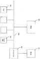
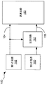
本発明の実装形態は、複数の回路基板を有するコンピュータシステムのための電力管理システムを提供する。電力管理システムは、コンピュータシステムの回路基板わたって延在する電力管理バスと、電力管理バスに通信可能に結合された複数のプラットフォーム管理制御装置とを含み、ここで、各プラットフォーム管理制御装置は、異なる回路基板上に位置され、各々の回路基板上の電源を制御するように構成される。 Implementations of the present invention provide a power management system for a computer system having a plurality of circuit boards. The power management system includes a power management bus extending across a circuit board of the computer system and a plurality of platform management controllers communicatively coupled to the power management bus, wherein each platform management controller is Located on different circuit boards and configured to control the power supply on each circuit board.
少なくともいくつかの実装形態では、各プラットフォーム管理制御装置は、論理ゲート内に完全に実装される。プラットフォーム管理制御装置は、コンピュータがオンに切り替えられているかどうかに関わらず、コンピュータシステムが入力電源に接続されているときはいつでも動作するように構成することができる。また、プラットフォーム管理制御装置は、コンピュータシステムの任意の電源を活動化できるようになる前に他のプラットフォーム管理制御装置がアクティブ状態であることを保証するように構成することもできる。プラットフォーム管理制御装置は、制御装置専用の鍵を生成することによって他のプラットフォーム管理制御装置がアクティブ状態であることを確認することができる。これらの鍵は、電力管理バスを使用して、他の制御装置に渡され、他の制御装置がアクティブ状態であるときに、受信されたように、他の制御装置によって送られ、それにより、各制御装置は、それ独自の鍵を再び受信するときに、すべての制御装置がアクティブ状態であることを知る。 In at least some implementations, each platform management controller is fully implemented in a logic gate. The platform management controller can be configured to operate whenever the computer system is connected to an input power source, regardless of whether the computer is switched on. The platform management controller can also be configured to ensure that other platform management controllers are active before any power supply of the computer system can be activated. The platform management control device can confirm that another platform management control device is in an active state by generating a key dedicated to the control device. These keys are passed to other controllers using the power management bus and sent by other controllers as received when other controllers are active, thereby Each control device knows that all control devices are active when it receives its own key again.
本発明の実装形態は、コンピュータシステムの速度を改良すると共に、コンピュータシステム内のプロセッサベースのコンピュータ構成要素をエミュレートするためのシステムを提供する。プロセッサベースのコンピュータ構成要素をエミュレートするためのシステムは、論理ゲートのみを使用してプロセッサベースのコンピュータ構成要素をエミュレートするように構成された論理ゲートベースの装置を含み、ここで、論理ゲートは、プロセッサベースのコンピュータ構成要素によって通常取り扱われるコマンドセットを受信し、プロセッサベースのコンピュータ構成要素によって通常出力されるものと同じ出力を、しかしはるかに高速で提供するように構成される。いくつかの実装形態では、論理ゲートは、プロセッサベースのコンピュータ構成要素によって通常取り扱われるすべての可能なコマンドのサブセットのみを認識してそれらに応答するように構成される。論理ゲートベースの装置は、コンピュータシステムによって積極的には使用されないが、1)コンピュータシステムの基本入出力システム(BIOS)と、2)コンピュータシステムのオペレーティングシステム(OS)との一方の適切な動作にその存在が必要とされるレガシーコンピュータ装置のエミュレーションを提供することができる。 Implementations of the present invention provide a system for improving the speed of a computer system and emulating processor-based computer components within the computer system. A system for emulating processor-based computer components includes a logic gate-based device configured to emulate a processor-based computer component using only logic gates, wherein the logic gates Is configured to receive a command set normally handled by a processor-based computer component and to provide the same output as that normally output by the processor-based computer component, but at a much faster rate. In some implementations, the logic gate is configured to recognize and respond to only a subset of all possible commands normally handled by processor-based computer components. Logic gate based devices are not actively used by computer systems, but for proper operation of one of the computer system's basic input / output system (BIOS) and 2) the computer system's operating system (OS). It can provide emulation of legacy computing devices whose presence is required.
本発明の特定の実装形態は、デジタル通信を符号化、送信、および復号するための方法を提供し、ここで、通信のデータ部分は、受信されるデータ部分の妥当性に関するチェックサム情報を本来的に含み、さらなるデータビットを必要としない。この方法は、デジタルデータの特定のパターンが無効となるような方式を使用してデジタルストリームに情報を符号化するステップと、送信機を使用してデジタルストリームを繰り返し送信するステップとを含む。受信機は、受信情報を受信し、受信情報は、有効および無効のパターンに関して評価される。受信情報は、有効な開始パターンに1つまたは複数の有効なデータパターンが続くときにのみ保持および復号される。 Certain implementations of the present invention provide a method for encoding, transmitting, and decoding a digital communication, where the data portion of the communication inherently contains checksum information regarding the validity of the received data portion. Including no additional data bits. The method includes encoding information into the digital stream using a scheme such that a particular pattern of digital data is invalid, and repeatedly transmitting the digital stream using a transmitter. The receiver receives the received information, and the received information is evaluated for valid and invalid patterns. Received information is retained and decoded only when a valid start pattern is followed by one or more valid data patterns.
開始パターンは、データストリームに含まれるデータのタイプに関する情報を含むことがある。また、開始パターンは、デジタルストリームが繰り返された回数に関する情報を含むこともある。 The start pattern may include information regarding the type of data included in the data stream. The start pattern may also include information regarding the number of times the digital stream has been repeated.
本発明の実装形態は、コンピュータシステム内に組み込まれたプラットフォーム管理制御装置を使用してコンピュータシステムの起動および機能動作を監視するための方法を提供する。この方法は、コンピュータシステムにプラットフォーム管理制御装置を提供するステップを含み、プラットフォーム管理制御装置は、コンピュータシステムの電力を管理し、かつコンピュータシステムの機能動作に関する情報をコンピュータシステムから取得することができるようにコンピュータシステムに接続され、さらに、プラットフォーム管理制御装置は、送信機に動作可能に接続される。また、この方法は、プラットフォーム管理制御装置を使用して、コンピュータシステムの起動および動作を監視するステップと、プラットフォーム管理制御装置を使用して、コンピュータシステムの起動および動作の少なくとも一方に関係付けられる事象のログを取るステップと、プラットフォーム管理制御装置を使用して、ログを取られた事象を送信機を使用して送信するステップとを含む。 Implementations of the present invention provide a method for monitoring the startup and functional operation of a computer system using a platform management controller embedded in the computer system. The method includes providing a platform management controller to a computer system, the platform management controller managing power of the computer system and obtaining information about the functional operation of the computer system from the computer system. And the platform management controller is operably connected to the transmitter. The method also includes the step of monitoring the startup and operation of the computer system using the platform management controller, and the event related to at least one of the startup and operation of the computer system using the platform management controller. And logging a logged event using a transmitter using a platform management controller.
ログを取られた事象は、起動時にコンピュータシステムによって生成されるポストコードを含むことがある。ログを取られた事象がポストコードを含むとき、プラットフォーム管理制御装置は、起動時点でポストコードを送信することができる。追加または代替として、ログを取られた事象は、シャットダウンの時点および異常な温度の検出時点の1つでコンピュータシステムから取得される温度読取値を含むことがある。いくつかの実装形態では、コンピュータシステムのオペレーティングシステムが、外部への送信のためにプラットフォーム管理制御装置にメッセージを送るように構成される。 Logged events may include postcode generated by the computer system at startup. When the logged event includes a postcode, the platform management controller can send the postcode at startup. In addition or alternatively, the logged event may include a temperature reading taken from the computer system at one of the time of shutdown and the detection of abnormal temperature. In some implementations, the operating system of the computer system is configured to send a message to the platform management controller for outbound transmission.
本発明の実装形態は、電力供給追跡装置を提供するための技法に関する。特に、本発明の少なくともいくつかの実装形態は、演算回路への第1の電力入力が演算回路への第2の電力入力に対して所定の関係を保つことを保証するための電力供給追跡装置に関する。 Implementations of the invention relate to techniques for providing a power supply tracking device. In particular, at least some implementations of the present invention provide a power supply tracking device for ensuring that a first power input to an arithmetic circuit maintains a predetermined relationship with a second power input to the arithmetic circuit. About.
本発明の実装形態は、基準電圧源と、比較器と、スイッチとを有する電力供給追跡装置を含む。基準電圧源は、比較器の第1の入力に基準電圧を提供する。比較器の第2の入力は、第1の電力入力に結合される。比較器の出力は、基準電圧と第1の電力入力の相対電圧の関数として状態を切り替える。比較器の出力は、スイッチを制御し、すなわち基準電圧と第1の電力入力の相対電圧に従ってスイッチを開閉する。スイッチは、電源と第2の電力入力の間に配設される。したがって、第2の電力入力を第1の電力入力に対して所定の関係で保つことができる。 Implementations of the invention include a power supply tracking device having a reference voltage source, a comparator, and a switch. The reference voltage source provides a reference voltage to the first input of the comparator. The second input of the comparator is coupled to the first power input. The output of the comparator switches state as a function of the reference voltage and the relative voltage of the first power input. The output of the comparator controls the switch, ie opens and closes the switch according to the reference voltage and the relative voltage of the first power input. The switch is disposed between the power source and the second power input. Thus, the second power input can be kept in a predetermined relationship with the first power input.
本発明の実装形態の方法およびプロセスは、パーソナルコンピューティングエンタープライズの分野で特に有用であることが実証されているが、本発明の方法およびプロセスを、様々な異なる適用分野、およびカスタマイズ可能なエンタープライズを生成するための様々な異なる製造分野で使用することができることを当業者は理解されよう。そのようなエンタープライズには、制御システムまたはスマートインターフェースシステムを利用する任意の産業のためのエンタープライズ、および/またはそのような装置の実装から利益を得るエンタープライズが含まれる。限定はしないが、そのような産業の例には、自動車産業、航空産業、液圧制御産業、自動/ビデオ制御産業、電気通信産業、医療産業、特殊応用産業、および家庭用電気機械器具産業が含まれる。したがって、本発明のシステムおよび方法は、現在のコンピュータ技法によって従来は未開拓であった市場を含めた多くの異なる市場に利益を提供することができる。 Although the implementation methods and processes of the present invention have proven to be particularly useful in the field of personal computing enterprises, the methods and processes of the present invention can be applied to a variety of different applications and customizable enterprises. One skilled in the art will appreciate that it can be used in a variety of different manufacturing fields to produce. Such enterprises include enterprises for any industry that utilizes control systems or smart interface systems, and / or enterprises that benefit from the implementation of such devices. Examples of such industries include, but are not limited to, the automotive industry, aviation industry, hydraulic control industry, auto / video control industry, telecommunications industry, medical industry, special application industry, and household electrical machinery industry. included. Thus, the system and method of the present invention can provide benefits to many different markets, including those previously pioneered by current computer techniques.
本発明の実装形態は、コンピュータシステム診断情報をワイヤレスで受信するため、およびそのような情報をカスタマイズ可能に表示するためのシステムおよび方法を提供する。この情報は、多様な汎用コンピュータシステムおよび多様な専用コンピュータシステムを含めた多様な既存および将来のコンピュータシステムから受信することができる。本明細書で開示するように、コンピュータシステムに組み込まれたプラットフォーム管理制御装置(PMC)または同様の装置が、コンピュータシステム情報を監視し、監視された情報を赤外線などによって送信または他の形で搬送する。本発明の実施形態は、送信された情報を受信し、それにより、本明細書で開示するものなど様々な目的にその情報を使用することができる。 Implementations of the present invention provide systems and methods for receiving computer system diagnostic information wirelessly and for displaying such information in a customizable manner. This information can be received from a variety of existing and future computer systems, including a variety of general purpose computer systems and a variety of dedicated computer systems. As disclosed herein, a platform management controller (PMC) or similar device embedded in a computer system monitors computer system information and transmits or otherwise conveys the monitored information, such as by infrared light To do. Embodiments of the present invention can receive transmitted information so that it can be used for a variety of purposes, such as those disclosed herein.
本発明の実装形態では、PMCまたは他の同様の装置によって送信される複数のログを取られた事象を、ワイヤレス診断装置などの診断装置によって受信して監視することができる。本発明の少なくともいくつかの実装形態では、診断装置の処理機能は、論理ゲート内に本質的にまたは完全に実装される。本明細書で詳細に述べるように、そのような実装形態は、特定の利点を提供する。 In implementations of the invention, multiple logged events sent by a PMC or other similar device may be received and monitored by a diagnostic device, such as a wireless diagnostic device. In at least some implementations of the invention, the processing functions of the diagnostic device are implemented essentially or completely within the logic gate. As described in detail herein, such an implementation provides certain advantages.
本発明の実装形態は、一時的電気接続に関する。特に、本発明は、情報をプリント回路基板(PCB)から受信する、またはPCBに送信するために、外部装置をPCBに一時的に接続するためのシステムおよび方法に関する。 Implementations of the invention relate to temporary electrical connections. In particular, the present invention relates to a system and method for temporarily connecting an external device to a PCB for receiving or transmitting information from a printed circuit board (PCB).
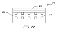
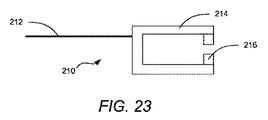
本発明の実装形態は、接続を介するデータの転送を容易に実現するために、外部データ源とPCBの間の一時的電気接続に関連付けて行われる。少なくとも1つの実装形態では、一時的電気システムは、PCBの1つまたは複数の縁部に隣接して配設された電気接触パッドを有するPCBを含む。電気接触パッドはさらに、PCB上の特定の位置に電気的に接続される。さらに、システムは、一時的電気コネクタ装置を含み、一時的電気コネクタ装置はさらに、電気ワイヤリボンと、電気ワイヤリボンの遠位端にあるヘッドとを含み、ヘッドは、そこに配設された1つまたは複数の電気接触パッドを有し、これらの電気接触パッドは、PCBの縁部に配設された電気パッドに対応する。 Implementations of the invention are made in connection with a temporary electrical connection between an external data source and the PCB to facilitate the transfer of data over the connection. In at least one implementation, the temporary electrical system includes a PCB having electrical contact pads disposed adjacent to one or more edges of the PCB. The electrical contact pads are further electrically connected to specific locations on the PCB. In addition, the system includes a temporary electrical connector device, the temporary electrical connector device further includes an electrical wire ribbon and a head at a distal end of the electrical wire ribbon, the head disposed therein. One or more electrical contact pads, which correspond to electrical pads disposed on the edge of the PCB.
さらなる実装形態では、PCBと一時的に電気的に接続するように適合された装置が、電気ワイヤリボンを含む。さらに、この装置は、電気ワイヤリボンの遠位端にヘッドを含み、ヘッドは、そこに配設された1つまたは複数の電気接触パッドを有する。いくつかの実装形態では、ヘッドはまた、そこに設けられた接着剤を有し、接着剤は、電気接触パッドを実質的に取り囲む。使用前には、接着剤は非接着性の裏当紙などによって保護されており、使用時に、この裏当紙を剥がすことができる。別の実装形態では、ヘッドは圧縮取付具を含み、圧縮取付具は、PCBなど対応する表面にヘッドが一時的に固定されるように、ヘッドに張力付与するように操作することができる。さらに別の実装形態では、ヘッドは、ピンまたは他のロケータを含み、これらを使用して、ヘッドとPCBなど対応する表面との一時的な接続を容易に成すことができる。さらに別の実装形態では、ヘッドは、動作可能なばねによって接続された2つの向かい合う顎部から構成され、ばねは、顎部を閉じた位置に偏倚し、したがって、ユーザが顎部を選択的に開いて、PCBなど対応する表面にヘッドを一時的に「クリップ留め」することができる。さらに別の実装形態では、ヘッドは、PCBの幅だけ接続可能に離隔された2つの向かい合う静止表面から構成され、それにより、ヘッドをPCBの縁部の上で一時的に滑動させて、そこに一時的に固定することができる。 In a further implementation, an apparatus adapted for temporary electrical connection with a PCB includes an electrical wire ribbon. The apparatus further includes a head at the distal end of the electrical wire ribbon, the head having one or more electrical contact pads disposed thereon. In some implementations, the head also has an adhesive provided thereon, the adhesive substantially surrounding the electrical contact pad. Prior to use, the adhesive is protected by a non-adhesive backing paper or the like, and the backing paper can be peeled off during use. In another implementation, the head includes a compression fitting that can be manipulated to tension the head such that the head is temporarily secured to a corresponding surface, such as a PCB. In yet another implementation, the head includes pins or other locators that can be used to facilitate a temporary connection between the head and a corresponding surface, such as a PCB. In yet another implementation, the head is composed of two opposing jaws connected by an actuable spring that biases the jaw to a closed position so that the user can selectively move the jaw. Open and temporarily “clip” the head to a corresponding surface, such as a PCB. In yet another implementation, the head is comprised of two opposing stationary surfaces that are connectably spaced by the width of the PCB, thereby allowing the head to temporarily slide over the edge of the PCB and into it. Can be temporarily fixed.
本発明の実装形態の方法およびプロセスは、一時的なPCB接続の分野で特に有用であることが実証されているが、これらの方法およびプロセスを、様々な異なる適用分野、および簡便で安価な一時的電気接続を生成するための様々な異なる製造分野で使用することができることを当業者は理解することができる。 Although the implementation methods and processes of the present invention have proven to be particularly useful in the field of temporary PCB connections, these methods and processes can be used in a variety of different applications and in a convenient and inexpensive temporary process. One skilled in the art can appreciate that it can be used in a variety of different manufacturing fields to create electrical connections.
本発明の目的および特徴は、添付図面に関連付けて成される以下の説明および添付の特許請求の範囲からより完全に明らかになろう。これらの図面は本発明の典型的な実施形態のみを示し、したがって本発明の範囲の限定とみなすべきではないという理解の下で、添付図面を使用してさらに具体性および詳細を伴って本発明を説明する。 The objects and features of the invention will become more fully apparent from the following description and appended claims, taken in conjunction with the accompanying drawings. With the understanding that these drawings depict only typical embodiments of the invention and therefore should not be considered as limiting the scope of the invention, the invention will be described with additional specificity and detail using the accompanying drawings. Will be explained.
次に、図面を参照して本発明の実施形態を説明する。本発明は多くの他の形態および形状を取ることができると考えられ、したがって、以下の開示は、限定ではなく例示として意図され、本発明の範囲は、添付の特許請求の範囲を参照して決定すべきである。 Next, embodiments of the present invention will be described with reference to the drawings. It is contemplated that the present invention can take many other forms and shapes, and thus the following disclosure is intended to be exemplary rather than limiting, and the scope of the present invention should be determined with reference to the appended claims Should be decided.
本発明の実施形態は、コンピュータシステムおよびコンピュータシステム操作の様々な側面の知的であり柔軟な管理および監視を行うためのシステムおよび方法を提供する。本発明の実施形態は、多様な汎用コンピュータシステムおよび多様な専用コンピュータシステムを含めた多様な既存および将来のコンピュータシステムに適用可能である。本発明を様々な方法で実装することができるコンピュータシステムの1つのクラスまたは構成は、「Non−Peripherals Processing Control Module Having Improved Heat Dissipating Properties」という名称の米国特許第7,256,991号明細書、「Robust Customizable Computer Processing System」という名称の米国特許第7,242,574号明細書、および「Systems and Methods for Providing a Dynamically Modular Processing Unit」という名称の米国特許第7,075,784号明細書に開示されており、上記特許を、それらが開示することすべてについて参照により本明細書に明示的に援用する。 Embodiments of the present invention provide systems and methods for intelligent and flexible management and monitoring of various aspects of computer systems and computer system operations. Embodiments of the present invention are applicable to a variety of existing and future computer systems, including a variety of general purpose computer systems and a variety of dedicated computer systems. One class or configuration of computer systems in which the present invention may be implemented in various ways is described in US Pat. No. 7,256,991, entitled “Non-Peripheral Processing Control Having Improved Heat Dissipating Properties”, United States Patent No. 7,242,574 entitled "Robust Customizable Computer Processing System" and "Systems and Methods for Providing a Dynamically Modular Processing No. 75 Patent No. 7" Disclosed above Huh, they expressly incorporated herein by reference for all that is disclosed.
上記の特許に開示されているものなど複数の相互接続された回路基板を有して使用するように構成されたコンピュータシステム内で、本発明の特定の実施形態は、認可された回路基板のみがコンピュータシステム内で使用されることを保証するためのシステムを提供する。このシステムは、各回路基板上に位置された認可チップを含む。各認可チップは、1)コンピュータの1つが機能動作するため、および認可チップが位置する回路基板が機能動作するために必要な鍵機能と、2)回路基板が試験されており、コンピュータシステム内で適切に機能動作するものとして認可されていることを通信する認可機能とを含む。また、このシステムは、認可通信バスも含み、認可通信バスは、システム内に組み込まれた各回路基板の認可ステータスを検証するために各認可チップが互いに通信できるようにする。少なくともいくつかのそのようなシステムでは、各認可チップは、認可チップを有さない回路基板がコンピュータシステムに取り付けられている場合には、コンピュータシステムが機能動作するのを妨げるように構成される。 Within a computer system configured for use with a plurality of interconnected circuit boards, such as those disclosed in the above patents, certain embodiments of the present invention are only authorized circuit boards. A system is provided for ensuring use in a computer system. The system includes an authorization chip located on each circuit board. Each authorization chip has 1) the key functions necessary for one of the computers to function and the circuit board on which the authorization chip is located, and 2) the circuit board has been tested and is within the computer system And an authorization function that communicates that it is authorized to function properly. The system also includes an authorized communication bus that allows the authorized chips to communicate with each other to verify the authorized status of each circuit board incorporated in the system. In at least some such systems, each authorization chip is configured to prevent the computer system from functioning when a circuit board that does not have the authorization chip is attached to the computer system.
特定の実施形態では、各認可チップは、各々の回路基板の状態を監視するように構成される。認可チップは、監視される回路基板の状態の記録を保持することができ、各認可チップは、各々の回路基板の状態のレポートを送信するように構成されることもある。 In certain embodiments, each authorization chip is configured to monitor the status of each circuit board. The authorization chip may maintain a record of the status of the circuit board being monitored, and each authorization chip may be configured to send a report of the status of each circuit board.
コンピュータシステムに関する電力制御に各認可チップが知的に関与するように構成されるいくつかの実施形態では、認可チップは、協働して、コンピュータシステムに関する複数の電源をオンおよびオフに切り替えるタイミングに関与する。いくつかのそのような実施形態では、認可チップは、逐次順序において先行するすべての電源が適切にオンに切り替わっていることを検証した後でのみ、チップに安全な順序でコンピュータの電源を逐次にオンに切り替えることによって、コンピュータシステムのチップを破壊する危険があることが分かっている電力状態がコンピュータシステム内で生じるのを共同で防止する。追加または代替として、認可チップは、コンピュータシステム内での電源故障の検出後にオン状態のままであるとチップの損壊を引き起こすことがある電源を迅速にオフに切り替えることによって、コンピュータシステムのチップを破壊する危険があることが分かっている電力状態がコンピュータシステム内で生じるのを共同で防止する。 In some embodiments where each authorization chip is configured to intelligently participate in power control for the computer system, the authorization chips cooperate to switch multiple power sources for the computer system on and off. Involved. In some such embodiments, the authorization chip sequentially turns on the computer's power supplies in a chip-safe order only after verifying that all previous power supplies in the sequential order are properly turned on. By switching on, it jointly prevents the occurrence of power conditions in the computer system that are known to be at risk of destroying the chip of the computer system. In addition or as an alternative, an authorized chip destroys the computer system chip by quickly switching off the power supply that can remain on after detection of a power failure in the computer system, which can cause chip damage Jointly prevent power conditions that are known to be in danger of occurring in the computer system.
少なくともいくつかの実施形態では、認可チップは、電力制御を監視して電源の活動化および非活動化を制御するように構成された論理ゲートを備え、それにより、1つの電源が故障したときに、コンピュータシステムの損壊を防止するのに十分に速く他の電源の非活動化が行われる。少なくともいくつかの実施形態では、他の電源の非活動化は、数クロックサイクル以内に行われる。 In at least some embodiments, the authorization chip comprises a logic gate configured to monitor power control and control activation and deactivation of the power supply, so that when one power supply fails Other power supplies are deactivated fast enough to prevent damage to the computer system. In at least some embodiments, the deactivation of other power supplies occurs within a few clock cycles.
実装されるとき、認可チップは、コンピュータシステムがオフに切り替えられている場合でさえ、コンピュータシステムが電源に接続されているときにはいつでも動作することができる。認可チップは、コンピュータシステムのサイドバンド管理を行い、論理ゲートのみを使用してサイドバンド管理を行うことができる。 When implemented, the authorization chip can operate whenever the computer system is connected to a power source, even when the computer system is switched off. The authorization chip performs sideband management of the computer system and can perform sideband management using only logic gates.
特定の実施形態では、認可チップ内部の論理ゲートによって故障事象が検出および記録され、認可チップは、協働して、故障事象のログを取り、コンピュータシステムをシャットダウンするように構成される。認可チップは、次の電源投入試行、および故障の時点の1つまたは複数で、故障事象の記録を送信するように構成することができる。 In certain embodiments, failure events are detected and recorded by logic gates within the authorization chip, and the authorization chips are configured to cooperate to log the failure event and shut down the computer system. The authorization chip can be configured to send a record of the failure event at one or more of the next power-on attempt and the time of the failure.
いくつかの実施形態では、認可チップは、コンピュータシステムが動作しているときに、集積回路間(I2C)バスやローピンカウント(LPC)バスなどコンピュータシステムの1つまたは複数のバス上で行われる通信をスヌープするように構成される。認可チップは、入出力(I/O)通信やポストコードなど、スヌープされた通信に応答するように構成されることがある。 In some embodiments, the authorization chip runs on one or more buses of the computer system, such as an inter-integrated circuit (I 2 C) bus or a low pin count (LPC) bus, when the computer system is operating. Configured to snoop on communication. The authorization chip may be configured to respond to snooped communications, such as input / output (I / O) communications and postcode.
本発明のいくつかの実施形態では、認可チップの1つまたは複数は、論理ゲートを使用してリアルタイムプロセッサエミュレーションを提供するように構成される。リアルタイムプロセッサエミュレーションを提供する1つまたは複数の認可チップは、選択された入力に対する特定の選択された出力を自動的にかつ迅速に提供することができる。特定の例では、1つまたは複数の認可チップが、PS/2キーボードコントローラおよびビデオコントローラの1つのエミュレーションを提供する。 In some embodiments of the invention, one or more of the authorization chips are configured to provide real-time processor emulation using logic gates. One or more authorization chips that provide real-time processor emulation can automatically and quickly provide specific selected outputs for selected inputs. In a particular example, one or more authorization chips provide one emulation of the PS / 2 keyboard controller and video controller.
特定の実施形態では、認可チップは、電源が最初にコンピュータシステムに接続されるときに、コンピュータシステムをオンに切り替えて使用できるようになる前に各認可チップがアクティブ状態になって機能動作する準備が整っていることを保証するために、認可チップが互いに通信できるように構成される。 In certain embodiments, the authorization chip is ready to function and operate each authorization chip when it is first connected to the computer system before the computer system can be turned on and used. To ensure that the authorization chips are in communication with each other.
特定の実施形態はコンピュータシステム内で行われ、その際、コンピュータシステム内に組み込まれ、論理ゲートのみを使用してコンピュータシステムのサイドバンド管理を提供するサイドバンド管理装置を使用して、コンピュータシステムの組込型サイドバンド管理を提供するためのシステムが提供される。サイドバンド管理装置は、電源入力時にコンピュータシステムの電源の活動化の適切なシーケンスを保証する電源投入管理を提供することができる。サイドバンド管理装置は、損壊を引き起こす可能性がある不適切な電圧組合せがコンピュータシステム内で生じるのを防止する様式でのみ電源の活動化が行われることを保証することができる。サイドバンド管理装置は、1つまたは複数の電源が活動化できなかったときには、電源シーケンスを中断し、コンピュータシステムをオフに切り替え、故障状態の詳細のログを取るように構成することができる。 Certain embodiments are performed in a computer system, using a sideband management device that is incorporated into the computer system to provide sideband management of the computer system using only logic gates. A system is provided for providing embedded sideband management. The sideband management device can provide power-on management that ensures an appropriate sequence of power activation of the computer system at power-on. The sideband management device can ensure that power activation is only performed in a manner that prevents inappropriate voltage combinations that can cause damage from occurring in the computer system. The sideband management device can be configured to interrupt the power sequence, switch off the computer system, and log the details of the fault condition when one or more power supplies cannot be activated.
特定の実施形態のサイドバンド管理装置は、コンピュータシステムの複数の回路基板にわたって分散された複数の装置を含むことができる。それとは無関係に、コンピュータシステムがオフに切り替えられているときにも、サイドバンド管理装置は電力供給されたままであることがある。特定の実施形態では、コンピュータシステムが単一のコンピュータ装置であり、サイドバンド管理装置がコンピュータ装置の少なくとも1つの回路基板に組み込まれ、それにより、サイドバンド管理装置は、別個のプロセッサまたはコンピュータ装置を含まない。 Certain embodiments of the sideband management device may include multiple devices distributed across multiple circuit boards of the computer system. Regardless, the sideband management device may remain powered even when the computer system is switched off. In certain embodiments, the computer system is a single computer device and the sideband management device is incorporated into at least one circuit board of the computer device, whereby the sideband management device includes a separate processor or computer device. Not included.
本発明の実施形態は、コンピュータシステムの機能動作に必要な異なる電圧の複数の電源を備えるコンピュータシステムにおいて、電源の活動化を制御するための方法を提供する。この方法は、複数の電源の1つまたは複数の活動化を選択的に命令するステップと、活動化されるように命令された電源が適切にオンに切り替わったかどうか監視するステップとを含む。活動化されるように命令された電源の1つまたは複数が設定時間内に適切にオンに切り替わらなかったときには、方法は、故障事象のログを取り、コンピュータシステムをオフに切り替えるステップを含む。 Embodiments of the present invention provide a method for controlling power supply activation in a computer system comprising multiple power supplies of different voltages required for functional operation of the computer system. The method includes selectively instructing one or more activations of a plurality of power sources and monitoring whether the power source commanded to be activated has been properly switched on. If one or more of the power supplies commanded to be activated do not properly turn on within a set time, the method includes logging a fault event and turning the computer system off.
この方法のいくつかの実施形態では、電源は、不適切な電圧シーケンスによって引き起こされるコンピュータシステムの構成要素の損壊を防止するように設計されたシーケンスで活動化され、活動化のシーケンスが継続される前に、各電源の活動化が適切な活動化であるか監視される。少なくともいくつかの実施形態では、コンピュータシステムをオフに切り替えるステップは、不適切な電圧シーケンスによって引き起こされるコンピュータシステムの構成要素の損壊を防止する順序で、オン状態の任意の電源を非活動化するステップを含む。 In some embodiments of the method, the power source is activated in a sequence designed to prevent damage to the components of the computer system caused by an improper voltage sequence and the activation sequence is continued. Before each power source activation is monitored for proper activation. In at least some embodiments, switching off the computer system includes deactivating any on-state power supply in an order that prevents damage to the components of the computer system caused by an improper voltage sequence. including.
本発明の実施形態は、複数の回路基板を有するコンピュータシステムのための電力管理システムを提供する。電力管理システムは、コンピュータシステムの回路基板わたって延在する電力管理バスと、電力管理バスに通信可能に結合された複数のプラットフォーム管理制御装置(PMC)とを含み、ここで、各PMCは、異なる回路基板上に位置され、各々の回路基板上の電源を制御するように構成される。 Embodiments of the present invention provide a power management system for a computer system having a plurality of circuit boards. The power management system includes a power management bus extending across the circuit board of the computer system and a plurality of platform management controllers (PMCs) communicatively coupled to the power management bus, wherein each PMC is Located on different circuit boards and configured to control the power supply on each circuit board.
少なくともいくつかの実施形態では、各PMCは、論理ゲート内に完全に実装される。PMCは、コンピュータがオンに切り替えられているかどうかに関わらず、コンピュータシステムが入力電源に接続されているときはいつでも動作するように構成することができる。また、PMCは、コンピュータシステムの任意の電源を活動化できるようになる前に他のPMCがアクティブ状態であることを保証するように構成することもできる。PMCは、制御装置専用の鍵を生成することによって他のPMCがアクティブ状態であることを確認することができる。これらの鍵は、電力管理バスを使用して、他の制御装置に渡され、他の制御装置がアクティブ状態であるときに、受信されたように、他の制御装置によって送られ、それにより、各制御装置は、それ独自の鍵を再び受信するときに、すべての制御装置がアクティブ状態であることを知る。 In at least some embodiments, each PMC is fully implemented in a logic gate. The PMC can be configured to operate whenever the computer system is connected to an input power source, regardless of whether the computer is switched on. The PMC can also be configured to ensure that other PMCs are active before any power supply of the computer system can be activated. The PMC can confirm that another PMC is in an active state by generating a key dedicated to the control device. These keys are passed to other controllers using the power management bus and sent by other controllers as received when other controllers are active, thereby Each control device knows that all control devices are active when it receives its own key again.
本発明の実施形態は、コンピュータシステムの速度を改良すると共に、コンピュータシステム内のプロセッサベースのコンピュータ構成要素をエミュレートするためのシステムを提供する。プロセッサベースのコンピュータ構成要素をエミュレートするためのシステムは、論理ゲートのみを使用してプロセッサベースのコンピュータ構成要素をエミュレートするように構成された論理ゲートベースの装置を含み、ここで、論理ゲートは、プロセッサベースのコンピュータ構成要素によって通常取り扱われるコマンドセットを受信し、プロセッサベースのコンピュータ構成要素によって通常出力されるものと同じ出力を、しかしはるかに高速で提供するように構成される。いくつかの実施形態では、論理ゲートは、プロセッサベースのコンピュータ構成要素によって通常取り扱われるすべての可能なコマンドのサブセットのみを認識してそれらに応答するように構成される。論理ゲートベースの装置は、コンピュータシステムによって積極的には使用されないが、1)コンピュータシステムの基本入出力システム(BIOS)と、2)コンピュータシステムのオペレーティングシステム(OS)との一方の適切な動作にその存在が必要とされるレガシーコンピュータ装置のエミュレーションを提供することができる。 Embodiments of the present invention provide a system for improving the speed of a computer system and emulating processor-based computer components within the computer system. A system for emulating processor-based computer components includes a logic gate-based device configured to emulate a processor-based computer component using only logic gates, wherein the logic gates Is configured to receive a command set normally handled by a processor-based computer component and to provide the same output as that normally output by the processor-based computer component, but at a much faster rate. In some embodiments, the logic gate is configured to recognize and respond to only a subset of all possible commands normally handled by processor-based computer components. Logic gate based devices are not actively used by computer systems, but for proper operation of one of the computer system's basic input / output system (BIOS) and 2) the computer system's operating system (OS). It can provide emulation of legacy computing devices whose presence is required.
本発明の特定の実施形態は、デジタル通信を符号化、送信、および復号するための方法を提供し、ここで、通信のデータ部分は、受信されるデータ部分の妥当性に関するチェックサム情報を本来的に含み、さらなるデータビットを必要としない。この方法は、デジタルデータの特定のパターンが無効となるような方式を使用してデジタルストリームに情報を符号化するステップと、送信機を使用してデジタルストリームを繰り返し送信するステップとを含む。受信機は、受信情報を受信し、受信情報は、有効および無効のパターンに関して評価される。受信情報は、有効な開始パターンに1つまたは複数の有効なデータパターンが続くときにのみ保持および復号される。 Certain embodiments of the present invention provide a method for encoding, transmitting, and decoding digital communications, wherein the data portion of the communication inherently contains checksum information regarding the validity of the received data portion. Including no additional data bits. The method includes encoding information into the digital stream using a scheme such that a particular pattern of digital data is invalid, and repeatedly transmitting the digital stream using a transmitter. The receiver receives the received information, and the received information is evaluated for valid and invalid patterns. Received information is retained and decoded only when a valid start pattern is followed by one or more valid data patterns.
開始パターンは、データストリームに含まれるデータのタイプに関する情報を含むことがある。また、開始パターンは、デジタルストリームが繰り返された回数に関する情報を含むこともある。 The start pattern may include information regarding the type of data included in the data stream. The start pattern may also include information regarding the number of times the digital stream has been repeated.
本発明の実施形態は、コンピュータシステム内に組み込まれたPMCを使用してコンピュータシステムの起動および機能動作を監視するための方法を提供する。この方法は、コンピュータシステムにPMCを提供するステップを含み、ここで、PMCは、コンピュータシステムの電力を管理し、かつコンピュータシステムの機能動作に関する情報をコンピュータシステムから取得することができるようにコンピュータシステムに接続され、さらに、PMCは、送信機に動作可能に接続される。また、この方法は、PMCを使用して、コンピュータシステムの起動および動作を監視するステップと、PMCを使用して、コンピュータシステムの起動および動作の少なくとも一方に関係付けられる事象のログを取るステップと、PMCを使用して、ログを取られた事象を送信機を使用して送信するステップとを含む。 Embodiments of the present invention provide a method for monitoring the startup and functional operation of a computer system using a PMC embedded in the computer system. The method includes providing a PMC to a computer system, where the PMC manages the power of the computer system and allows the computer system to obtain information about the functional operation of the computer system from the computer system. In addition, the PMC is operatively connected to the transmitter. The method also includes monitoring the startup and operation of the computer system using the PMC and logging events related to at least one of the startup and operation of the computer system using the PMC. Using the PMC to transmit the logged event using the transmitter.
ログを取られた事象は、起動時にコンピュータシステムによって生成されるポストコードを含むことがある。ログを取られた事象がポストコードを含むとき、PMCは、起動時点でポストコードを送信することができる。追加または代替として、ログを取られた事象は、シャットダウンの時点および異常な温度の検出時点の一方でコンピュータシステムから取得される温度読取値を含むことがある。いくつかの実施形態では、コンピュータシステムのオペレーティングシステムが、外部への送信のためにPMCにメッセージを送るように構成される。 Logged events may include postcode generated by the computer system at startup. When the logged event includes a postcode, the PMC can send the postcode at startup. Additionally or alternatively, the logged event may include a temperature reading taken from the computer system at one of the time of shutdown and the time of abnormal temperature detection. In some embodiments, the operating system of the computer system is configured to send a message to the PMC for outbound transmission.
本発明の実施形態は、電力供給追跡装置を提供するための技法に関する。特に、本発明の少なくともいくつかの実施形態は、演算回路への第1の電力入力が演算回路への第2の電力入力に対して所定の関係を保つことを保証するための電力供給追跡装置に関する。 Embodiments of the invention relate to techniques for providing a power supply tracking device. In particular, at least some embodiments of the present invention provide a power supply tracking device for ensuring that a first power input to an arithmetic circuit maintains a predetermined relationship with a second power input to the arithmetic circuit. About.
本発明の実施形態は、基準電圧源と、比較器と、スイッチとを有する電力供給追跡装置を含む。基準電圧源は、比較器の第1の入力に基準電圧を提供する。比較器の第2の入力は、第1の電力入力に結合される。比較器の出力は、基準電圧と第1の電力入力の相対電圧の関数として状態を切り替える。比較器の出力は、スイッチを制御し、すなわち基準電圧と第1の電力入力の相対電圧に従ってスイッチを開閉する。スイッチは、電源と第2の電力入力の間に配設される。したがって、第2の電力入力を第1の電力入力に対して所定の関係で保つことができる。 Embodiments of the present invention include a power supply tracking device having a reference voltage source, a comparator, and a switch. The reference voltage source provides a reference voltage to the first input of the comparator. The second input of the comparator is coupled to the first power input. The output of the comparator switches state as a function of the reference voltage and the relative voltage of the first power input. The output of the comparator controls the switch, ie opens and closes the switch according to the reference voltage and the relative voltage of the first power input. The switch is disposed between the power source and the second power input. Thus, the second power input can be kept in a predetermined relationship with the first power input.
本発明の実施形態の方法およびプロセスは、パーソナルコンピューティングエンタープライズの分野で特に有用であることが実証されているが、本発明の方法およびプロセスを、様々な異なる適用分野、およびカスタマイズ可能なエンタープライズを生成するための様々な異なる製造分野で使用することができることを当業者は理解されよう。そのようなエンタープライズには、制御システムまたはスマートインターフェースシステムを利用する任意の産業のためのエンタープライズ、および/またはそのような装置の実施から利益を得るエンタープライズが含まれる。限定はしないが、そのような産業の例には、自動車産業、航空産業、液圧制御産業、自動/ビデオ制御産業、電気通信産業、医療産業、特殊応用産業、および家庭用電気機械器具産業が含まれる。したがって、本発明のシステムおよび方法は、現在のコンピュータ技法によって従来は未開拓であった市場を含めた多くの異なる市場に利益を提供することができる。 Although the methods and processes of embodiments of the present invention have proven to be particularly useful in the field of personal computing enterprises, the methods and processes of the present invention can be used in a variety of different applications and customizable enterprises. One skilled in the art will appreciate that it can be used in a variety of different manufacturing fields to produce. Such enterprises include enterprises for any industry that utilizes control systems or smart interface systems, and / or enterprises that benefit from the implementation of such devices. Examples of such industries include, but are not limited to, the automotive industry, aviation industry, hydraulic control industry, auto / video control industry, telecommunications industry, medical industry, special application industry, and household electrical machinery industry. included. Thus, the system and method of the present invention can provide benefits to many different markets, including those previously pioneered by current computer techniques.
本発明の実施形態は、コンピュータシステム診断情報をワイヤレスで受信するため、およびそのような情報をカスタマイズ可能に表示するためのシステムおよび方法を提供する。この情報は、多様な汎用コンピュータシステムおよび多様な専用コンピュータシステムを含めた多様な既存および将来のコンピュータシステムから受信することができる。本明細書で開示するように、コンピュータシステムに組み込まれたプラットフォーム管理制御装置(PMC)または同様の装置が、コンピュータシステム情報を監視し、監視された情報を赤外線などによって送信または他の形で搬送する。本発明の実施形態は、送信された情報を受信し、それにより、本明細書で開示するものなど様々な目的にその情報を使用することができる。 Embodiments of the present invention provide systems and methods for receiving computer system diagnostic information wirelessly and for displaying such information in a customizable manner. This information can be received from a variety of existing and future computer systems, including a variety of general purpose computer systems and a variety of dedicated computer systems. As disclosed herein, a platform management controller (PMC) or similar device embedded in a computer system monitors computer system information and transmits or otherwise conveys the monitored information, such as by infrared light To do. Embodiments of the present invention can receive transmitted information so that it can be used for a variety of purposes, such as those disclosed herein.
本発明の実施形態では、PMCまたは他の同様の装置によって送信される複数のログを取られた事象を、ワイヤレス診断装置などの診断装置によって受信して監視することができる。本発明の少なくともいくつかの実施形態では、診断装置の処理機能は、論理ゲート内に本質的にまたは完全に実装される。本明細書で詳細に述べるように、そのような実施形態は、特定の利点を提供する。本明細書で論じる診断装置の特定の実施形態は、論理ゲート装置を使用して実装されるが、診断装置が、当技術分野で現在知られているタイプまたは将来開発されるタイプの様々な他のコンピュータシステムに情報を提供する、または渡すことができることを理解されよう。例えば、少なくともいくつかの実施形態では、診断装置は、ユニバーサルシリアルバス(USB)接続やイーサネット(登録商標)接続など有線または無線接続を使用して外部コンピュータシステムに接続することができる。そのような接続は、PMCまたは他の同様の装置から通信が受信される時点、またはより後のある時点を含めた、診断装置の使用中の任意の時点で行うことができる。したがって、以下の論述は、何らかの理由で診断装置と共に使用される、または診断装置に接続されることがあるコンピュータシステムを説明する意図のものである。 In embodiments of the present invention, multiple logged events transmitted by a PMC or other similar device can be received and monitored by a diagnostic device, such as a wireless diagnostic device. In at least some embodiments of the present invention, the processing functions of the diagnostic device are implemented essentially or completely within the logic gate. As described in detail herein, such embodiments provide certain advantages. Although the specific embodiments of the diagnostic devices discussed herein are implemented using logic gate devices, the diagnostic devices may be of various other types of types currently known in the art or developed in the future. It will be appreciated that information can be provided or passed to any computer system. For example, in at least some embodiments, the diagnostic device can be connected to an external computer system using a wired or wireless connection, such as a universal serial bus (USB) connection or an Ethernet connection. Such a connection can be made at any time during use of the diagnostic device, including when a communication is received from a PMC or other similar device, or at some later time. Accordingly, the following discussion is intended to describe a computer system that may be used with or connected to a diagnostic device for any reason.
本発明の実施形態は、一時的電気接続に関する。特に、本発明は、情報をプリント回路基板(PCB)から受信する、またはPCBに送信するために、外部装置をPCBに一時的に接続するためのシステムおよび方法に関する。 Embodiments of the invention relate to temporary electrical connections. In particular, the present invention relates to a system and method for temporarily connecting an external device to a PCB for receiving or transmitting information from a printed circuit board (PCB).
本発明の実施形態は、接続を介するデータの転送を容易に実現するために、外部データ源とPCBの間の一時的電気接続に関連付けて行われる。少なくとも1つの実施形態では、一時的電気システムは、PCBの1つまたは複数の縁部に隣接して配設された電気接触パッドを有するPCBを含む。電気接触パッドはさらに、PCB上の特定の位置に電気的に接続される。さらに、システムは、一時的電気コネクタ装置を含み、一時的電気コネクタ装置はさらに、電気ワイヤリボンと、電気ワイヤリボンの遠位端にあるヘッドとを含み、ヘッドは、そこに配設された1つまたは複数の電気接触パッドを有し、これらの電気接触パッドは、PCBの縁部に配設された電気パッドに対応する。 Embodiments of the present invention are made in connection with a temporary electrical connection between an external data source and a PCB to facilitate the transfer of data over the connection. In at least one embodiment, the temporary electrical system includes a PCB having electrical contact pads disposed adjacent to one or more edges of the PCB. The electrical contact pads are further electrically connected to specific locations on the PCB. In addition, the system includes a temporary electrical connector device, the temporary electrical connector device further includes an electrical wire ribbon and a head at a distal end of the electrical wire ribbon, the head disposed therein. One or more electrical contact pads, which correspond to electrical pads disposed on the edge of the PCB.
さらなる実施形態では、PCBと一時的に電気的に接続するように適合された装置が、電気ワイヤリボンを含む。さらに、この装置は、電気ワイヤリボンの遠位端にヘッドを含み、ヘッドは、そこに配設された1つまたは複数の電気接触パッドを有する。いくつかの実施形態では、ヘッドはまた、そこに設けられた接着剤を有し、接着剤は、電気接触パッドを実質的に取り囲む。使用前には、接着剤は非接着性の裏当紙などによって保護されており、使用時に、この裏当紙を剥がすことができる。他の実施形態では、ヘッドは圧縮取付具を含み、圧縮取付具は、PCBなど対応する表面にヘッドが一時的に固定されるように、ヘッドに張力付与するように操作することができる。さらに他の実施形態では、ヘッドは、ピンまたは他のロケータを含み、これらを使用して、ヘッドとPCBなど対応する表面との一時的な接続を容易に成すことができる。さらに別の実施形態では、ヘッドは、動作可能なばねによって接続された2つの向かい合う顎部から構成され、ばねは、顎部を閉じた位置に偏倚し、したがって、ユーザが顎部を選択的に開いて、PCBなど対応する表面にヘッドを一時的に「クリップ留め」することができる。さらに他の実施形態では、ヘッドは、PCBの幅だけ接続可能に離隔された2つの向かい合う静止表面から構成され、それにより、ヘッドをPCBの縁部の上で一時的に滑動させて、そこに一時的に固定することができる。 In a further embodiment, an apparatus adapted for temporary electrical connection with a PCB includes an electrical wire ribbon. The apparatus further includes a head at the distal end of the electrical wire ribbon, the head having one or more electrical contact pads disposed thereon. In some embodiments, the head also has an adhesive provided thereon, the adhesive substantially surrounding the electrical contact pad. Prior to use, the adhesive is protected by a non-adhesive backing paper or the like, and the backing paper can be peeled off during use. In other embodiments, the head includes a compression fitting that can be operated to tension the head such that the head is temporarily secured to a corresponding surface, such as a PCB. In yet other embodiments, the head includes pins or other locators that can be used to facilitate a temporary connection between the head and a corresponding surface, such as a PCB. In yet another embodiment, the head is comprised of two opposing jaws connected by an actuable spring that biases the jaw to a closed position so that the user can selectively select the jaw. Open and temporarily “clip” the head to a corresponding surface, such as a PCB. In yet another embodiment, the head is comprised of two opposing stationary surfaces that are connectably spaced by the width of the PCB, thereby allowing the head to temporarily slide over the edge of the PCB and into it. Can be temporarily fixed.
本発明の実施形態の方法およびプロセスは、一時的なPCB接続の分野で特に有用であることが実証されているが、これらの方法およびプロセスを、様々な異なる適用分野、および簡便で安価な一時的電気接続を生成するための様々な異なる製造分野で使用することができることを当業者は理解することができる。 Although the methods and processes of embodiments of the present invention have proven to be particularly useful in the field of temporary PCB connections, these methods and processes can be used in a variety of different applications and in a convenient and inexpensive temporary process. One skilled in the art can appreciate that it can be used in a variety of different manufacturing fields to create electrical connections.
本発明の実施形態のいくつかの側面を、論述および明確さのために、様々な表題を使用して論じる。表題は、例示実施形態のいくつかの側面を理解しやすくするために与えたものにすぎず、何ら限定を意図していない。 Several aspects of embodiments of the present invention are discussed using various titles for discussion and clarity. The headings are provided merely to facilitate understanding of some aspects of the exemplary embodiments and are not intended to be limiting in any way.
代表的なコンピュータシステム
上述したように、本発明の実施形態は、多様なコンピュータシステムおよび構成で実装することができ、そのようなシステムおよび構成には、「Non−Peripherals Processing Control Module Having Improved Heat Dissipating Properties」という名称の米国特許第7,256,991号明細書、「Robust Customizable Computer Processing System」という名称の米国特許第7,242,574号明細書、および「Systems and Methods for Providing a Dynamically Modular Processing Unit」という名称の米国特許第7,075,784号明細書に開示されるものと同様のシステムおよび構成が含まれる。単に例示として、図1および図2は、米国特許第7,075,784号明細書の図1および図3の複製である。ここでは、元の参照番号のままにしてある。これらの図面および対応する論述(以下に本質的に転載する)は、本発明の少なくともいくつかの実施形態を実装することができる動作実施形態を提供することができる代表的なコンピュータシステムの第1の例を提供する。
Exemplary Computer Systems As noted above, embodiments of the present invention can be implemented in a variety of computer systems and configurations, including “Non-Peripheral Processing Control Modulated Improved Heat Dissipating”. U.S. Patent No. 7,256,991 entitled "Properties", U.S. Patent No. 7,242,574 entitled "Robust Customizable Computer Processing System", and United States named “Unit” Systems and configurations similar to those disclosed in US Pat. No. 7,075,784 are included. By way of example only, FIGS. 1 and 2 are reproductions of FIGS. 1 and 3 of US Pat. No. 7,075,784. Here, the original reference numbers are left as they are. These drawings and the corresponding discussion (reproduced essentially below) are the first of a representative computer system that can provide an operational embodiment capable of implementing at least some embodiments of the present invention. Provide an example.
図1および対応する論述は、本発明の実施形態による適切な動作環境の一般的な説明を行う意図のものである。以下にさらに論じるように、本発明の実施形態は、以下に論じるようなネットワーク化された構成または複合構成を含めた様々なカスタマイズ可能なエンタープライズ構成における1つまたは複数の動的モジュラー処理ユニットの使用を包含する。 FIG. 1 and the corresponding discussion are intended to provide a general description of a suitable operating environment according to an embodiment of the present invention. As discussed further below, embodiments of the present invention use one or more dynamic modular processing units in a variety of customizable enterprise configurations, including networked or composite configurations as discussed below. Is included.
本発明の実施形態は、非一時的および/または有形コンピュータ可読媒体を含めた1つまたは複数のコンピュータ可読媒体を包含し、ここで、各媒体は、データ、またはデータを操作するためのコンピュータ実行可能命令を含むように構成されることがあり、またはそれらを含む。コンピュータ実行可能命令は、データ構造、オブジェクト、プログラム、ルーチン、または他のプログラムモジュールを含み、これらに1つまたは複数のプロセッサがアクセスすることができ、そのようなプロセッサは、例えば、様々な異なる機能を実施することができる汎用モジュラー処理ユニットに関連付けられるもの、または限られた数の機能を実施することができる専用モジュラー処理ユニットに関連付けられるものである。 Embodiments of the present invention include one or more computer-readable media, including non-transitory and / or tangible computer-readable media, where each medium is data or computer-implemented for manipulating data. May or may be configured to include possible instructions. Computer-executable instructions include data structures, objects, programs, routines, or other program modules that can be accessed by one or more processors, such as, for example, various different functions. Associated with a general-purpose modular processing unit capable of performing a limited number of functions, or associated with a dedicated modular processing unit capable of performing a limited number of functions.
コンピュータ実行可能命令は、エンタープライズの1つまたは複数のプロセッサに特定の機能または機能群を実施させるものであり、処理の方法に関するステップを実施するためのプログラムコード手段の例である。さらに、実行可能命令の特定のシーケンスが、そのようなステップを実施するために使用することができる対応する動作の一例を提供する。 Computer-executable instructions, which cause one or more processors in an enterprise to perform a particular function or group of functions, are examples of program code means for performing steps relating to a method of processing. Further, a particular sequence of executable instructions provides an example of corresponding operations that can be used to perform such steps.
コンピュータ可読媒体の例には、ランダムアクセスメモリ(「RAM」)、読み出し専用メモリ(「ROM」)、プログラマブル読み出し専用メモリ(「PROM」)、消去可能なプログラマブル読み出し専用メモリ(「EPROM」)、電気的に消去可能なプログラマブル読み出し専用メモリ(「EEPROM」)、コンパクトディスク読み出し専用メモリ(「CD−ROM」)、任意のソリッドステート記憶装置(例えば、フラッシュメモリやスマートメディアなど)、または、処理ユニットがアクセスすることができるデータもしくは実行可能命令を提供することができる任意の他の装置もしくは構成要素が含まれる。 Examples of computer readable media include random access memory (“RAM”), read only memory (“ROM”), programmable read only memory (“PROM”), erasable programmable read only memory (“EPROM”), electrical Erasable programmable read-only memory ("EEPROM"), compact disc read-only memory ("CD-ROM"), any solid state storage device (eg, flash memory, smart media, etc.), or processing unit Any other device or component capable of providing accessible data or executable instructions is included.
図1を参照すると、代表的なエンタープライズは、汎用または専用処理ユニットとして使用することができるモジュラー処理ユニット10を含む。例えば、モジュラー処理ユニット10は、パーソナルコンピュータ、ノートブックコンピュータ、携帯情報端末(「PDA」)もしくは他のハンドヘルドデバイス、ワークステーション、ミニコンピュータ、メインフレーム、スーパーコンピュータ、マルチプロセッサシステム、ネットワークコンピュータ、プロセッサベースの家庭用電気機械器具、スマート機器もしくは装置、制御システムなどとして、単独で、あるいは1つまたは複数の同様のモジュラー処理ユニットと共に採用することができる。同じエンタープライズ内で複数の処理ユニットを使用することで、処理能力が高められる。例えば、エンタープライズの各処理ユニットは、特定のタスクに特化させることができ、または分散処理に共同で関与することができる。 Referring to FIG. 1, a typical enterprise includes a modular processing unit 10 that can be used as a general purpose or dedicated processing unit. For example, the modular processing unit 10 may be a personal computer, notebook computer, personal digital assistant ("PDA") or other handheld device, workstation, minicomputer, mainframe, supercomputer, multiprocessor system, network computer, processor-based As home appliances, smart appliances or devices, control systems, etc., can be employed alone or in conjunction with one or more similar modular processing units. By using multiple processing units within the same enterprise, processing power is increased. For example, each processing unit in the enterprise can be specialized for a specific task or can be jointly involved in distributed processing.
図1で、モジュラー処理ユニット10は、1つまたは複数のバスおよび/または相互接続12を含み、バス/相互接続12は、モジュラー処理ユニット10の様々な構成要素を接続するように構成することができ、2つ以上の構成要素の間でデータを交換できるようにする。バス/相互接続12は、様々なバスアーキテクチャの任意のものを使用するメモリバス、周辺機器バス、またはローカルバスを含めた様々なバス構造の1つを含むことができる。バス/相互接続12によって接続される典型的な構成要素には、1つまたは複数のプロセッサ14および1つまたは複数のメモリ16が含まれる。他の構成要素は、論理、1つまたは複数のシステム、1つまたは複数のサブシステム、および/または1つまたは複数のI/Oインターフェース(本明細書では以後「データ操作システム18」と呼ぶ)の使用によってバス/相互接続12に選択的に接続することができる。さらに、他の構成要素は、論理、1つまたは複数のシステム、1つまたは複数のサブシステム、および/または1つまたは複数のI/Oインターフェースの使用によってバス/相互接続12に外部から接続することができ、および/または、論理、1つまたは複数のシステム、1つまたは複数のサブシステム、および/または1つまたは複数のI/Oインターフェースとして機能することができ、例えば、モジュラー処理ユニット30および/または独自の装置34である。I/Oインターフェースの例には、1つまたは複数の大容量記憶装置インターフェース、1つまたは複数の入力インターフェース、1つまたは複数の出力インターフェースなどが含まれる。したがって、本発明の実施形態は、1つまたは複数のI/Oインターフェースを使用することができる機能、および/または採用される論理もしくは他のデータ操作システムに基づいて製品の有用性を変更することができる機能を包含する。
In FIG. 1, the modular processing unit 10 includes one or more buses and / or interconnects 12, which may be configured to connect various components of the modular processing unit 10. And allows data to be exchanged between two or more components. Bus / interconnect 12 may include one of a variety of bus structures including a memory bus, a peripheral bus, or a local bus using any of a variety of bus architectures. Typical components connected by the bus / interconnect 12 include one or
論理は、インターフェース、システムの一部、サブシステムに結び付けることができ、および/または特定のタスクを実施するために使用することができる。したがって、論理または他のデータ操作システムは、例えばIEEE1394(ファイアワイヤ)を考慮に入れることがあり、ここで、論理または他のデータ操作システムはI/Oインターフェースである。代替または追加として、モジュラー処理ユニットを別の外部システムもしくはサブシステムに結び付けることができるようにする論理または別のデータ操作システムを使用することもできる。例えば、外部システムまたはサブシステムは、特別なI/O接続を含むことも、含まないこともある。代替または追加として、外部I/Oが論理に関連付けられていない形で、論理または他のデータ操作システムを使用することができる。また、本発明の実施形態は、例えば車両用や液圧制御システム用のECUのための特殊論理、および/またはハードウェアの特定の部品を制御する方法をプロセッサに知らせる論理の使用を包含する。さらに、本発明の実施形態が、論理、システム、サブシステム、および/またはI/Oインターフェースを利用する多くの異なるシステムおよび/または構成を包含することを当業者は理解されよう。 The logic can be tied to interfaces, parts of the system, subsystems, and / or can be used to perform specific tasks. Thus, a logic or other data manipulation system may take into account, for example, IEEE 1394 (Firewire), where the logic or other data manipulation system is an I / O interface. Alternatively or additionally, logic or another data manipulation system can be used that allows the modular processing unit to be linked to another external system or subsystem. For example, an external system or subsystem may or may not include special I / O connections. Alternatively or additionally, logic or other data manipulation systems can be used in a manner that external I / O is not associated with logic. Embodiments of the present invention also include the use of special logic for ECUs, for example for vehicles and hydraulic control systems, and / or logic to inform the processor how to control specific parts of the hardware. Moreover, those skilled in the art will appreciate that embodiments of the invention encompass many different systems and / or configurations that utilize logic, systems, subsystems, and / or I / O interfaces.
上述したように、本発明の実施形態は、1つまたは複数のI/Oインターフェースを使用することができる機能、および/または採用される論理もしくは他のデータ操作システムに基づいて製品の有用性を変更することができる機能を包含する。例えば、モジュラー処理ユニット10が、デスクトップコンピュータとして使用するために設計された1つまたは複数のI/Oインターフェースおよび論理を含むパーソナルコンピューティングシステムの一部である場合、論理または他のデータ操作システムは、2つの標準のRCAを介してアナログ音声を録音し、それらをIPアドレスにブロードキャストすることを望む音楽ステーション向けに音声符号化を行うためにフラッシュメモリまたは論理を含むように変更することができる。したがって、モジュラー処理ユニット10は、モジュラー処理ユニット10のバックプレーン上のデータ操作システム(例えば、論理、システム、サブシステム、I/Oインターフェースなど)に施される修正により、コンピュータシステムではない機器として使用されるシステムの一部となり得る。したがって、バックプレーン上のデータ操作システムの修正により、モジュラー処理ユニットの用途を変えることができる。したがって、本発明の実施形態は、非常に適応性のあるモジュラー処理ユニット10を包含する。 As described above, embodiments of the present invention provide product usability based on the ability to use one or more I / O interfaces and / or the logic or other data manipulation system employed. Includes functions that can be changed. For example, if the modular processing unit 10 is part of a personal computing system that includes one or more I / O interfaces and logic designed for use as a desktop computer, the logic or other data manipulation system is It can be modified to include flash memory or logic to record analog voices via two standard RCAs and perform voice encoding for music stations that wish to broadcast them to IP addresses. Thus, the modular processing unit 10 is used as equipment that is not a computer system due to modifications made to the data manipulation system (eg, logic, system, subsystem, I / O interface, etc.) on the backplane of the modular processing unit 10 Can be part of the system. Thus, the modification of the data manipulation system on the backplane can change the usage of the modular processing unit. Accordingly, embodiments of the present invention include a highly adaptive modular processing unit 10.
上述したように、処理ユニット10は、1つまたは複数のプロセッサ14、例えば中央プロセッサを含み、さらに任意選択で、特定の機能またはタスクを実施するように設計された1つまたは複数の他のプロセッサを含む。典型的には、プロセッサ14が、コンピュータ可読媒体、例えばメモリ16、磁気ハードディスク、着脱可能な磁気ディスク、磁気カセット、光ディスクに提供されている命令、またはやはりコンピュータ可読媒体とみなすことができる通信接続からの命令を実行する。
As described above, the processing unit 10 includes one or
メモリ16は、1つまたは複数のコンピュータ可読媒体を含み、コンピュータ可読媒体は、データ、またはデータを操作するための命令を含むように構成されることがあり、またはそれらを含み、バス/相互接続12を介してプロセッサ14がアクセスすることができる。メモリ16は、例えば、永久的に情報を記憶するために使用されるROM20、および/または一時的に情報を記憶するために使用されるRAM22を含むことができる。ROM20は、モジュラー処理ユニット10の起動中などに通信を確立するために使用される1つまたは複数のルーチンを有する基本入出力システム(「BIOS」)を含むことができる。動作中、RAM22は、1つまたは複数のプログラムモジュール、例えば1つまたは複数のオペレーティングシステム、アプリケーションプログラム、および/またはプログラムデータを含むことができる。
The memory 16 includes one or more computer readable media, which may be configured to include or include data, or instructions for manipulating data, a bus / interconnect 12 can be accessed by the
例示されるように、本発明の少なくともいくつかの実施形態は、周辺機器を含まない筐体を包含し、これは、より頑強な処理ユニットを提供し、様々な異なる用途でのユニットの使用を可能にする。図1において、(データ操作システム18として示される)1つまたは複数の大容量記憶装置インターフェースを使用して、1つまたは複数の大容量記憶装置24をバス/相互接続12に接続することができる。大容量記憶装置24は、モジュラー処理ユニット10の周辺機器であり、モジュラー処理ユニット10が大量のデータを保持できるようにする。大容量記憶装置の例には、ハードディスクドライブ、磁気ディスクドライブ、テープドライブ、光ディスクドライブ、およびソリッドステートドライブが含まれる。
As illustrated, at least some embodiments of the present invention include a housing that does not include peripherals, which provides a more robust processing unit and allows the use of the unit in a variety of different applications. to enable. In FIG. 1, one or more mass storage device interfaces (shown as data manipulation system 18) can be used to connect one or more
大容量記憶装置24は、磁気ハードディスク、着脱可能な磁気ディスク、磁気カセット、光ディスク、ソリッドステートメモリ、または別のコンピュータ可読媒体からの読出しを行う、および/またはそれらへの書込みを行うことができる。大容量記憶装置24およびそれらの対応するコンピュータ可読媒体は、データおよび/または実行可能命令の不揮発性記憶を提供し、そのようなデータおよび/または実行可能命令は、1つまたは複数のプログラムモジュール、例えばオペレーティングシステム、1つまたは複数のアプリケーションプログラム、他のプログラムモジュール、またはプログラムデータを含むことがある。そのような実行可能命令は、本明細書で開示する方法のためのステップを実施するためのプログラムコード手段の例である。
The
1つまたは複数の対応する周辺I/O装置26を介してデータおよび/または命令をモジュラー処理ユニット10と交換できるようにデータ操作システム18を採用することができる。周辺I/O装置26の例には、キーボードなどの入力装置、および/または代替入力装置、例えば、マウス、トラックボール、ライトペン、スタイラス、もしくは他のポインティングデバイス、マイクロフォン、ジョイスティック、ゲームパッド、サテライトディッシュ、スキャナ、カムコーダ、デジタルカメラ、センサなど、および/または出力装置、例えば、モニタもしくは表示画面、スピーカ、プリンタ、制御システムなどが含まれる。同様に、バス/相互接続12に周辺I/O装置26を接続するために使用することができる特殊化された論理と結合されたデータ操作システム18の例には、シリアルポート、パラレルポート、ゲームポート、ユニバーサルシリアルバス(「USB」)、ファイアワイヤ(IEEE1394)、ワイヤレス受信機、ビデオアダプタ、オーディオアダプタ、パラレルポート、ワイヤレス送信機、任意のパラレルもしくはシリアルI/O周辺機器、または別のインターフェースが含まれる。
The data manipulation system 18 may be employed so that data and / or instructions can be exchanged with the modular processing unit 10 via one or more corresponding peripheral I /
データ操作システム18は、1つまたは複数のネットワークインターフェース28にわたる情報の交換を可能にする。ネットワークインターフェース28の例には、処理ユニット間で情報を交換できるようにする接続、ローカルエリアネットワーク(「LAN」)への接続用のネットワークアダプタもしくはモデム、ワイヤレスリンク、またはインターネットなどワイドエリアネットワーク(「WAN」)への接続用の別のアダプタが含まれる。ネットワークインターフェース28は、モジュラー処理ユニット10に組み込まれることがあり、またはモジュラー処理ユニット10の周辺機器であることもあり、LAN、ワイヤレスネットワーク、WAN、および/または処理ユニット間の任意の接続に関連付けられることがある。 Data manipulation system 18 allows for the exchange of information across one or more network interfaces 28. Examples of network interface 28 include connections that allow information to be exchanged between processing units, network adapters or modems for connection to a local area network (“LAN”), a wireless link, or a wide area network (“ Another adapter for connection to the WAN "). The network interface 28 may be incorporated into the modular processing unit 10 or may be a peripheral device of the modular processing unit 10 and is associated with any connection between the LAN, wireless network, WAN, and / or processing unit. Sometimes.
データ操作システム18は、モジュラー処理ユニット10が、1つまたは複数の他のローカルまたは遠隔モジュラー処理ユニット30またはコンピュータ装置と情報を交換できるようにする。モジュラー処理ユニット10とモジュラー処理ユニット30の接続は、ハードワイヤードおよび/またはワイヤレスリンクを含むことがある。したがって、本発明の実施形態は、直接バス間接続を包含する。これは、大きなバスシステムの構築を可能にする。また、エンタープライズの直接バス間接続により、現在知られているハッキングを防ぐ。さらに、データ操作システム18は、モジュラー処理ユニット10が、1つまたは複数の独自のI/O接続手段32および/または1つまたは複数の独自の装置34と情報を交換できるようにする。
Data manipulation system 18 enables modular processing unit 10 to exchange information with one or more other local or remote
処理ユニットがアクセス可能なプログラムモジュールまたはそれらの一部は、遠隔メモリ記憶装置に記憶することができる。さらに、ネットワーク化されたシステムまたは複合構成では、モジュラー処理ユニット10は、分散コンピューティング環境に関与することができ、分散コンピューティング環境では、機能またはタスクが複数の処理ユニットによって行われる。あるいは、複合構成/エンタープライズの各処理ユニットは、特定のタスクに特化させることもできる。したがって、例えば、エンタープライズの1つの処理ユニットは、ビデオデータに特化されることがあり、それにより、従来のビデオカードに取って代わり、そのようなタスクを実施するために従来の技法よりも高い処理能力を提供する。 The program modules accessible by the processing unit or parts thereof can be stored in a remote memory storage device. Further, in a networked system or complex configuration, modular processing unit 10 may participate in a distributed computing environment, where functions or tasks are performed by multiple processing units. Alternatively, each processing unit of the composite configuration / enterprise can be specialized for a specific task. Thus, for example, one processing unit in the enterprise may be specialized for video data, thereby replacing traditional video cards and higher than conventional techniques to perform such tasks Provide processing power.
本発明の実施形態が様々な構成を備えることができることを当業者は理解されるであろうが、耐久性のある動的モジュラー処理ユニットの代表的な実施形態を示す図2を参照する。図2の例示実施形態では、処理ユニット40は、耐久性があり、動的モジュラーである。例示実施形態では、ユニット40は、冷却ファンを必要としない高度な熱力学的冷却モデルを利用する約3.5インチ(8.9cm)の立方形のプラットフォームである。
Those skilled in the art will appreciate that embodiments of the present invention can have a variety of configurations, but refer to FIG. 2, which shows an exemplary embodiment of a durable dynamic modular processing unit. In the exemplary embodiment of FIG. 2, the
しかし、本明細書で述べるように、本発明の実施形態は、熱力学的冷却プロセスに加えて、またはその代わりに、強制空気冷却プロセスおよび/または液体冷却プロセスなど他の冷却プロセスの使用も包含する。さらに、例示実施形態は、3.5インチの立方形のプラットフォームを含むが、本発明の実施形態が、3.5インチの立方形プラットフォームよりも大きいまたは小さいモジュラー処理ユニットの使用も包含することを当業者は理解されよう。同様に、他の実施形態は、立方形以外の形状の使用も包含する。 However, as described herein, embodiments of the present invention also include the use of other cooling processes such as forced air cooling processes and / or liquid cooling processes in addition to or instead of thermodynamic cooling processes. To do. Further, although the exemplary embodiment includes a 3.5 inch cubic platform, embodiments of the present invention also encompass the use of modular processing units that are larger or smaller than the 3.5 inch cubic platform. Those skilled in the art will appreciate. Similarly, other embodiments encompass the use of shapes other than cubic.
また、処理ユニット40は、処理とメモリの割合を最適化する層状のマザーボード構成と、性能を向上させると共にハードウェアとソフトウェア両方の安定性を高めるバスアーキテクチャとを含む。本発明の他の実施形態が非層状マザーボードも包含することを当業者は理解されよう。さらに、本発明の他の実施形態は、埋込型のマザーボード構成を包含し、この構成では、マザーボードの構成要素が1つまたは複数の材料に埋め込まれ、それらの材料が、構成要素間の絶縁を提供し、1つまたは複数の材料に構成要素を埋め込み、マザーボード構成要素の1つまたは複数は、機械的、光学的、電気的、または電気機械的なものである。さらに、埋込型のマザーボード構成の実施形態の少なくともいくつかは、3次元の無菌環境内に固定された機械的、光学的、電気的、および/または電気機械的な構成要素を含む。そのような材料の例には、ポリマー、ゴム、エポキシ、および/または任意の非導電性の封入化合物が含まれる。
The
本発明の実施形態は、処理の多用性を提供することを包含する。例えば、本発明の少なくともいくつかの実施形態によれば、処理の負担が識別され、次いで、処理能力を選択的に集中させる、および/または割り振ることによって解決される。例えば、具体的な要求に従って特定のシステムが定義され、それにより、処理能力の集中または割振りが制御される。したがって、1つまたは複数のモジュラー処理ユニットは、そのような具体的な要求(例えば、ビデオ、オーディオ、1つまたは複数のシステム、1つまたは複数のサブシステムなど)に合わせて処理能力を提供するように特化されることがある。いくつかの実施形態では、処理能力を提供することができることが、中央ユニットに対する負荷を減少させる。したがって、処理能力は、必要とされる領域に向けられる。 Embodiments of the present invention include providing processing versatility. For example, according to at least some embodiments of the present invention, processing burdens are identified and then resolved by selectively centralizing and / or allocating processing power. For example, a specific system is defined according to specific requirements, thereby controlling the concentration or allocation of processing power. Thus, one or more modular processing units provide processing power to meet such specific requirements (eg, video, audio, one or more systems, one or more subsystems, etc.). May be specialized. In some embodiments, being able to provide processing power reduces the load on the central unit. Thus, processing power is directed to the required area.
例示実施形態では、処理ユニット40は2GHzのプロセッサと1.5GBのRAMを含むが、本発明の他の実施形態が、より高速または低速のプロセッサおよび/またはより大きいまたは小さいRAMの使用も包含することを当業者は理解されよう。本発明の少なくともいくつかの実施形態では、プロセッサの速度および処理ユニットのRAMの量は、処理ユニットの使用の性質に依存する。
In the exemplary embodiment, processing
非常に動的であり、カスタマイズ可能であり、交換可能であるバックプレーン44が、周辺機器および垂直型の用途に対する支持を提供する。例示実施形態では、バックプレーン44は、筐体42に選択的に結合され、ユニット40を動的にカスタマイズ可能にする1つまたは複数の特徴、インターフェース、機能、論理、および/または構成要素を含むことができる。例示実施形態では、バックプレーン44は、DVIビデオポート46と、イーサネット(登録商標)ポート48と、USBポート50(50aおよび50b)と、SATAバスポート52(52aおよび52b)と、電源ボタン54と、電源ポート56とを含む。また、上述したようにシステム全体の処理能力を高めるため、および以下にさらに開示するようにスケール変更された処理を提供するために、バックプレーン44は、2つ以上のモジュラー処理ユニットを一体に電気的に結合させるメカニズムを含むこともできる。
A very dynamic, customizable and
バックプレーン44と、その対応する特徴、インターフェース、機能、論理、および/または構成要素は、代表的なものにすぎず、本発明の実施形態が、様々な異なる特徴、インターフェース、機能、および/または構成要素を有するバックプレーンを包含することを当業者は理解されよう。したがって、処理ユニットは、あるバックプレーンを別のバックプレーンに取り替えることができるようにすることによって動的にカスタマイズ可能であり、処理ユニットの論理、特徴、および/または機能をユーザが選択的に変更できるようにする。
The
さらに、本発明の実施形態は、任意の数および/またはタイプの論理および/またはコネクタを包含して、様々な異なる環境における1つまたは複数のモジュラー処理ユニット40の使用を可能にする。例えば、そのような環境には、車両(例えば、車、トラック、オートバイなど)、液圧制御システム、および他の環境が含まれる。以下にさらに論じるように、バックプレーン上のデータ操作システムの変更は、様々な環境に対して、垂直方向および/または水平方向でスケール変更を可能にする。
Furthermore, embodiments of the present invention include any number and / or type of logic and / or connectors to enable the use of one or more
さらに、本発明の実施形態は、様々な形状およびサイズのモジュラー処理ユニットを包含する。例えば、図2において、モジュラー処理ユニット40は、様々な理由から、従来の処理ユニットよりも小さい立方体である。
Furthermore, embodiments of the present invention include modular processing units of various shapes and sizes. For example, in FIG. 2, the
当業者に明らかなように、本発明の実施形態は、例えば、使用される材料、サイズおよび/または形状、論理のタイプ、および/または周辺機器ベースの筐体がないことにより、従来の技法よりもサポートが容易である。 As will be apparent to those skilled in the art, embodiments of the present invention are more advantageous than conventional techniques, for example, due to the lack of materials, sizes and / or shapes used, logic types, and / or peripheral-based enclosures. Is also easy to support.
例示実施形態では、電源ボタン54は、パワーブートに関する3つの状態、すなわちオン、オフ、およびスタンバイを含む。電源がオンに切り替えられて電力が受け取られるとき、ユニット40は、メモリにサポートされたオペレーティングシステムをロードしてブートするように命令される。電源がオフに切り替えられるとき、処理制御ユニット40は、任意の進行中の処理を中断し、シャットダウンシーケンスを開始し、それに続いてスタンバイ状態になり、この状態で、システムは、電源投入状態に作動されるのを待機する。
In the illustrated embodiment, the
USBポート50は、周辺入力/出力装置を処理ユニット40に接続するように構成される。そのような入力または出力装置の例には、キーボード、マウスもしくはトラックボール、モニタ、プリンタ、別の処理ユニットもしくはコンピュータ装置、モデム、およびカメラが含まれる。
The USB port 50 is configured to connect a peripheral input / output device to the
SATAバスポート52は、処理ユニット40の周辺機器である大容量記憶装置を電子的に結合およびサポートするように構成される。そのような大容量記憶装置の例には、フロッピー(登録商標)ディスクドライブ、CD−ROMドライブ、ハードドライブ、テープドライブなどが含まれる。
The SATA bus port 52 is configured to electronically couple and support a mass storage device that is a peripheral device of the
上述したように、当業者に理解されるように、本発明の他の実施形態は、周辺装置を接続するための追加のポートおよび手段の使用も包含する。したがって、本明細書で特に識別して説明する接続用の特定のポートおよび手段は、例示にすぎず、何ら限定はしないものと意図される。 As mentioned above, as will be appreciated by those skilled in the art, other embodiments of the present invention also include the use of additional ports and means for connecting peripheral devices. Accordingly, the specific ports and means for connection specifically identified and described herein are intended to be illustrative only and not limiting in any way.
本明細書で述べるように、周辺機器を含まない処理ユニットの使用によって、より大きな、周辺機器を詰め込んだコンピュータユニットに勝る様々な利点が存在する。例えば、ユーザは、エンタープライズに収容するのに必要な空間を選択的に縮小することができ、それでも、必要な全体の空間を依然としてより小さくしたままでシステムに処理ユニットを追加することによって、より高い処理能力を提供することができる。さらに、各処理ユニットは、故障しがちなシステムではなくソリッドステート構成要素を含むので、個々のユニットを(例えば、壁、家具、クローゼット、時計などの装飾デバイスに)隠すことができる。 As described herein, the use of a processing unit that does not include peripherals offers various advantages over a computer unit that is packed with peripherals. For example, the user can selectively reduce the space required to accommodate the enterprise, but still higher by adding processing units to the system while still keeping the overall space required smaller Processing power can be provided. Furthermore, each processing unit includes solid state components rather than a system that is prone to failure, so individual units can be hidden (eg, in decorative devices such as walls, furniture, closets, watches, etc.).
個々の処理ユニット/立方体の耐久性により、従来の技法では普通は考えられなかった位置で処理を行うことができるようになる。例えば、処理ユニットは、地面に埋める、水中に位置させる、海中に埋める、地中数百フィートに打ち込むドリルビットのヘッドに配置する、または家具の不安定な表面上に配置することができる。処理位置の可能性は無限にある。他の利点としては、雑音および熱の減少、ならびに、家具、固定具、車両、構造、支持体、機器、計器、日用品など消費者に利用可能な様々な装置にカスタマイズ可能な「スマート」技術を提供できることが挙げられる。 The durability of the individual processing units / cubes allows processing to be performed at locations not normally thought of by conventional techniques. For example, the treatment unit can be buried in the ground, located in the water, buried in the sea, placed on the head of a drill bit driven into the ground several hundred feet, or placed on an unstable surface of furniture. There are endless possibilities for processing positions. Other benefits include noise and heat reduction, as well as “smart” technology that can be customized to a variety of consumer-available devices such as furniture, fixtures, vehicles, structures, supports, equipment, instruments, and daily necessities. It can be provided.
図2において、この図は、立方体の側壁を取り除いた状態で処理ユニット40を示し、周辺機器ベースでない筐体42、冷却プロセス(例えば、熱力学的な対流冷却、強制空気冷却、および/または液体冷却)、最適化された層状の回路基板構成、および動的なバックプレーン44をより完全に示す。例示実施形態では、様々な回路基板が、圧力ばめ技法を使用することによって一体に結合され、この技法は、回路基板の偶発的な外れを防止し、かつ交換可能性を提供する。回路基板は、向上されたEMI分散および/またはチップ/論理配置を提供する。本発明の実施形態が任意の数の回路基板および/または構成を包含することを当業者は理解されよう。さらに、回路基板構造は、1つまたは複数の用途および/または機能に基づいて、特定の利益および/または要求に合わせて変更することができる。図2で、処理ユニット40は、層状回路基板/マザーボード構成60を含み、この構成60は、2枚の平行なサイドボード62(62aおよび62b)と、サイドボード62に対して横方向であり、サイドボード62を電子的に結合させる中央ボード64とを含む。例示実施形態は、3枚の回路基板を有する構成を提供するが、本発明の実施形態が、3つ未満の回路基板を有する回路基板構成、および4つ以上の回路基板を有する層状回路基板構成も包含することを当業者は理解されよう。さらに、本発明の実施形態は、互いに直角を成す回路基板以外の他の回路基板構成も包含する。
In FIG. 2, this figure shows the
例示実施形態では、層状マザーボード60は、マザーボード60を筐体42に結合するための手段を使用して、筐体42の内部に支持される。例示実施形態では、マザーボード60を筐体42に結合するための手段は、マザーボード60の少なくとも一部分を選択的に受け取ってマザーボード60を定位置に保持するように構成された様々なチャネル型スロットを含む。先端技術を用いたアップグレードが必要なとき、例えばプロセッサ66を改良されたプロセッサと交換すべきときには、対応する回路基板(例えば中央ボード64)が筐体42から取り外されて、新たなプロセッサを備える新たな回路基板が挿入されて、アップグレードを可能にする。したがて、本発明の実施形態は、必要に応じたアップグレートを容易にし、カスタマイズ可能であり動的な処理ユニットを提供することが実証されている。
In the illustrated embodiment, the layered
また、処理ユニット40は、1つまたは複数のタスクを実施するように構成された1つまたは複数のプロセッサを含む。図2で、1つまたは複数のプロセッサは、プロセッサ66として示されており、プロセッサ66は、中央ボード64に結合される。技術が進歩するにつれて、処理ユニット40のユーザが、プロセッサ66をアップグレードされたプロセッサに交換することを望む時が来ることがある。その際、中央ボード64を筐体42から取り外すことができ、アップグレードされたプロセッサを有する新たな中央ボードを、ユニット40に関連付けて設置して使用することができる。したがって、本発明の実施形態は、従来の技法とは異なり容易にアップグレードされ、したがって長寿命のプラットフォームを提供する、動的にカスタマイズ可能な処理ユニットを包含する。
The
図3および対応する論述は、本発明の少なくともいくつかの実施形態を実装することができる別の適切な動作環境を全般的に説明する意図のものである。本発明の実施形態は、1つまたは複数のコンピューティング装置によって、ネットワーク化された構成を含めた様々なシステム構成で実施することができることを当業者は理解されよう。しかし、本発明の方法およびプロセスは、汎用コンピュータを備えるシステムに関連付けて有用であることが実証されているが、本発明の実施形態は、様々な環境での方法およびプロセスの利用を含み、そのような環境には、汎用処理ユニットを有する埋込型システム、デジタル/メディア信号プロセッサ(DSP/MSP)、特定用途向け集積回路(ASIC)、スタンドアローン電子デバイス、および他のそのような電子的な環境が含まれる。 FIG. 3 and the corresponding discussion are intended to generally describe another suitable operating environment in which at least some embodiments of the present invention may be implemented. Those skilled in the art will appreciate that embodiments of the invention may be implemented by one or more computing devices in a variety of system configurations, including networked configurations. However, while the methods and processes of the present invention have proven useful in connection with systems comprising general purpose computers, embodiments of the present invention include the use of the methods and processes in various environments, and Such environments include embedded systems with general purpose processing units, digital / media signal processors (DSP / MSP), application specific integrated circuits (ASICs), stand-alone electronic devices, and other such electronic The environment is included.
本発明の実施形態は、1つまたは複数のコンピュータ可読媒体を包含し、ここで、各媒体は、データ、およびデータを操作するためのコンピュータ実行可能命令を含むように構成されることがあり、またはそれらを含む。コンピュータ実行可能命令は、データ構造、オブジェクト、プログラム、ルーチン、または他のプログラムモジュールを含み、これらに処理システムがアクセスすることができ、そのようなプロセッサは、例えば、様々な異なる機能を実施することができる汎用コンピュータに関連付けられるもの、または限られた数の機能を実施することができる専用コンピュータに関連付けられるものである。コンピュータ可読命令は、処理システムに特定の機能または機能群を実施させるものであり、本明細書に開示する方法に関するステップを実施するためのプログラムコード手段の例である。さらに、実行可能命令の特定のシーケンスが、そのようなステップを実施するために使用することができる対応する動作の一例を提供する。コンピュータ可読媒体の例には、ランダムアクセスメモリ(「RAM」)、読み出し専用メモリ(「ROM」)、プログラマブル読み出し専用メモリ(「PROM」)、消去可能なプログラマブル読み出し専用メモリ(「EPROM」)、電気的に消去可能なプログラマブル読み出し専用メモリ(「EEPROM」)、コンパクトディスク読み出し専用メモリ(「CD−ROM」)、または、処理ユニットがアクセスすることができるデータもしくは実行可能命令を提供することができる任意の他の装置もしくは構成要素が含まれる。本発明の実施形態は、すべてのタイプのコンピュータ可読媒体の使用を包含するが、特許請求の範囲に記載されている特定の実施形態は、有形および/または非一時的コンピュータ可読媒体の使用に限定されることがあり、本明細書で使用される「有形コンピュータ可読媒体」および「非一時的コンピュータ可読媒体」(または複数形)は、一時的な伝播信号自体を除外することを意図されている。 Embodiments of the invention include one or more computer-readable media, where each medium may be configured to include data and computer-executable instructions for manipulating the data, Or including them. Computer-executable instructions include data structures, objects, programs, routines, or other program modules that can be accessed by a processing system such as a processor performing various different functions, for example. Associated with a general purpose computer capable of performing a limited number of functions or associated with a dedicated computer capable of performing a limited number of functions. A computer readable instruction causes a processing system to perform a particular function or group of functions and is an example of program code means for performing steps relating to the methods disclosed herein. Further, a particular sequence of executable instructions provides an example of corresponding operations that can be used to perform such steps. Examples of computer readable media include random access memory (“RAM”), read only memory (“ROM”), programmable read only memory (“PROM”), erasable programmable read only memory (“EPROM”), electrical Erasable Programmable Read-Only Memory (“EEPROM”), Compact Disc Read-Only Memory (“CD-ROM”), or anything that can provide data or executable instructions that can be accessed by a processing unit Other devices or components are included. Although embodiments of the invention encompass the use of all types of computer readable media, the specific embodiments recited in the claims are limited to the use of tangible and / or non-transitory computer readable media. “Tangible computer readable medium” and “non-transitory computer readable medium” (or plurals) as used herein are intended to exclude the transient propagation signal itself. .
図3を参照すると、本発明の実施形態と共に使用するため、または本発明の実施形態を実装するための代表的なシステムは、コンピュータ装置70を含み、コンピュータ装置70は、汎用もしくは専用コンピュータ、または様々な家庭用電気機械器具の任意のものでよい。例えば、コンピュータ装置70は、パーソナルコンピュータ、ノートブックコンピュータ、ネットブック、携帯情報端末(「PDA」)もしくは他のハンドヘルドデバイス、ワークステーション、ミニコンピュータ、メインフレーム、スーパーコンピュータ、マルチプロセッサシステム、ネットワークコンピュータ、プロセッサベースの家庭用電気機械器具などでよい。 With reference to FIG. 3, an exemplary system for use with or implementing embodiments of the present invention includes a computer device 70, which may be a general purpose or special purpose computer, or It can be any of a variety of household electrical appliances. For example, the computer device 70 may be a personal computer, notebook computer, netbook, personal digital assistant (“PDA”) or other handheld device, workstation, minicomputer, mainframe, supercomputer, multiprocessor system, network computer, It may be a processor-based household electrical machine.
コンピュータ装置70は、システムバス72を含み、システムバス72は、コンピュータ装置70の様々な構成要素を接続するように構成することができ、2つ以上の構成要素の間でデータを交換できるようにする。システムバス72は、様々なバスアーキテクチャの任意のものを使用するメモリバス、周辺機器バス、またはローカルバスを含めた様々なバス構造の1つを含むことができる。システムバス72によって接続される典型的な構成要素には、処理システム74およびメモリ76が含まれる。他の構成要素には、1つまたは複数の大容量記憶装置インターフェース78、入力インターフェース80、出力インターフェース82、および/またはネットワークインターフェース84が含まれることがあり、それぞれを以下に論じる。
The computer device 70 includes a
処理システム74は、1つまたは複数のプロセッサ、例えば中央プロセッサを含み、さらに任意選択で、特定の機能またはタスクを実施するように設計された1つまたは複数の他のプロセッサを含む。典型的には、処理システム74が、コンピュータ可読媒体、例えばメモリ76、磁気ハードディスク、着脱可能な磁気ディスク、磁気カセット、光ディスクに提供されている命令、またはやはりコンピュータ可読媒体とみなすことができる通信接続からの命令を実行する。
The
メモリ76は、1つまたは複数のコンピュータ可読媒体を含み、コンピュータ可読媒体は、データ、またはデータを操作するための命令を含むように構成されることがあり、またはそれらを含み、システムバス72を介して処理システム74がアクセスすることができる。メモリ76は、例えば、永久的に情報を記憶するために使用されるROM88、および/または一時的に情報を記憶するために使用されるRAM90を含むことができる。ROM88は、コンピュータ装置70の起動中などに通信を確立するために使用される1つまたは複数のルーチンを有する基本入出力システム(「BIOS」)を含むことができる。RAM90は、1つまたは複数のプログラムモジュール、例えば1つまたは複数のオペレーティングシステム、アプリケーションプログラム、および/またはプログラムデータを含むことができる。
The memory 76 includes one or more computer readable media, which may be configured to include or include data, or instructions for manipulating data, including the
1つまたは複数の大容量記憶装置インターフェース78を使用して、1つまたは複数の大容量記憶装置86をシステムバス72に接続することができる。大容量記憶装置26は、コンピュータ装置70に組み込まれることがあり、またはコンピュータ装置70の周辺機器であることもあり、コンピュータ装置70が大量のデータを保持できるようにする。任意選択で、大容量記憶装置86の1つまたは複数は、コンピュータ装置70から取外し可能にすることもできる。大容量記憶装置の例には、ハードディスクドライブ、磁気ディスクドライブ、テープドライブ、ソリッドステートドライブ、および光ディスクドライブが含まれる。大容量記憶装置86は、磁気ハードディスク、着脱可能な磁気ディスク、磁気カセット、光ディスク、ソリッドステートデバイス、または別のコンピュータ可読媒体からの読出しを行う、および/またはそれらへの書込みを行うことができる。大容量記憶装置86およびそれらの対応するコンピュータ可読媒体は、データおよび/または実行可能命令の不揮発性記憶を提供し、そのようなデータおよび/または実行可能命令は、1つまたは複数のプログラムモジュール、例えばオペレーティングシステム、1つまたは複数のアプリケーションプログラム、他のプログラムモジュール、またはプログラムデータを含むことがある。そのような実行可能命令は、本明細書で開示する方法のためのステップを実施するためのプログラムコード手段の例である。
One or more mass storage device interfaces 78 may be used to connect one or more
ユーザが1つまたは複数の対応する入力装置92を介してコンピュータ装置70にデータおよび/または命令を入力することができるように、1つまたは複数の入力インターフェース80を採用することができる。そのような入力装置の例には、キーボードおよび代替入力装置、例えば、マウス、トラックボール、ライトペン、スタイラス、もしくは他のポインティングデバイス、マイクロフォン、ジョイスティック、ゲームパッド、サテライトディッシュ、スキャナ、カムコーダ、デジタルカメラなどが含まれる。同様に、入力装置92をシステムバス72に接続するために使用することができる入力インターフェース80の例には、シリアルポート、パラレルポート、ゲームポート、ユニバーサルシリアルバス(「USB」)、集積回路、ファイアワイヤ(IEEE1394)、または別のインターフェースが含まれる。例えば、いくつかの実施形態では、入力インターフェース80は、特定の用途のために設計された特定用途向け集積回路(ASIC)を含む。さらなる実施形態では、ASICが埋め込まれ、既存の回路構築ブロックを接続する。
One or more input interfaces 80 may be employed so that a user can enter data and / or instructions into the computing device 70 via one or more
1つまたは複数の対応する出力装置94をシステムバス72に接続するために1つまたは複数の出力インターフェース82を採用することができる。出力装置の例には、モニタもしくは表示画面、スピーカ、プリンタ、多機能周辺機器などが含まれる。特定の出力装置94は、コンピュータ装置70に組み込まれることがあり、またはコンピュータ装置70の周辺機器であることもある。出力インターフェースの例には、ビデオアダプタ、オーディオアダプタ、パラレルポートなどが含まれる。
One or
1つまたは複数のネットワークインターフェース84により、コンピュータ装置70は、ハードワイヤードおよび/またはワイヤレスリンクを含むことがあるネットワーク98を介して、コンピュータ装置96として示される1つまたは複数の他のローカルまたは遠隔コンピュータ装置と情報を交換できるようにされる。ネットワークインターフェースの例には、ローカルエリアネットワーク(「LAN」)への接続用のネットワークアダプタもしくはモデム、ワイヤレスリンク、またはインターネットなどワイドエリアネットワーク(「WAN」)への接続用の他のアダプタが含まれる。ネットワークインターフェース84は、コンピュータ装置70に組み込まれることがあり、またはコンピュータ装置70の周辺機器であることもある。ネットワーク化されたシステムでは、アクセス可能なプログラムモジュールまたはその一部を遠隔メモリ記憶装置に記憶することができる。さらに、ネットワーク化されたシステムでは、コンピュータ装置70は、分散コンピューティング環境に関与することができ、分散コンピューティング環境では、機能またはタスクが複数のネットワーク化されたコンピュータ装置によって行われる。
One or more network interfaces 84 allow the computer device 70 to display one or more other local or remote computers, shown as a computer device 96, over a
したがって、多くのタイプのシステム構成を有する様々な異なる環境で本発明の実施形態を実施することができることが当業者には理解されるが、図4は、本発明の特定の実施形態に関連付けて使用することができる代表的なネットワーク化システム構成を提供する。図4の代表的なシステムは、クライアント100として示されるコンピュータ装置を含み、クライアント100は、ネットワーク98を介して、1つまたは複数の他のコンピュータ装置(クライアント102およびクライアント104として示される)および1つまたは複数の周辺装置106(多機能周辺機器(MFP)MFPなど)に接続される。図4は、ネットワーク98に接続されたクライアント100と、2つの追加のクライアント、すなわちクライアント102およびクライアント104と、1つの周辺装置106と、任意選択のサーバ108とを含む実施形態を示すが、代替実施形態は、ネットワーク98に接続されたより多くのクライアントもしくはより少ないクライアントを含む、複数の周辺装置を含む、周辺装置を含まない、サーバ108を含まない、および/または複数のサーバ108を含む。本発明の他の実施形態は、ローカル環境、ネットワーク化された環境、またはピアツーピア環境を含み、1つまたは複数のコンピュータ装置を1つまたは複数のローカルまたは遠隔周辺装置に接続することができる。さらに、本発明による実施形態は、単一の家庭用電気機械器具、ワイヤレスネットワーク化環境、および/またはインターネットなどワイドエリアネットワーク化環境も包含する。
Thus, it will be appreciated by those skilled in the art that embodiments of the present invention may be implemented in a variety of different environments having many types of system configurations, although FIG. 4 is associated with a particular embodiment of the present invention. An exemplary networked system configuration that can be used is provided. The exemplary system of FIG. 4 includes a computing device shown as
プラットフォーム管理
上述した一般的なコンピュータシステムは、一般に本発明の実施形態と共に使用することができるコンピュータシステムの代表例である。以下、本発明の実施形態のいくつかの側面を、「Non−Peripherals Processing Control Module Having Improved Heat Dissipating Properties」という名称の米国特許第7,256,991号明細書、「Robust Customizable Computer Processing System」という名称の米国特許第7,242,574号明細書、および「Systems and Methods for Providing a Dynamically Modular Processing Unit」という名称の米国特許第7,075,784号明細書に開示されるタイプの特定のコンピュータシステムをより特定的に参照しながら、より詳細に説明する。本発明の特定の実施形態は、上記の特許に開示されるコンピュータシステムのタイプに関連付けられる特徴に特に適用可能であり得るが、他のコンピュータシステムタイプに適用可能な、本明細書で論じる本発明の様々な実施形態の任意の特徴が、そのようなコンピュータシステムタイプと共に使用するためのものとしても意図されることを理解すべきである。
Platform Management The general computer system described above is typically a representative example of a computer system that can be used with embodiments of the present invention. Hereinafter, some aspects of embodiments of the present invention are described in US Pat. No. 7,256,991 entitled “Non-Peripheral Processing Control Modulating Improved Heat Dissipating Properties”, “Robust Customizable Combusting Measures”. A specific computer of the type disclosed in US Pat. No. 7,242,574, entitled “Systems and Methods for Providing a Dynamical Modular Processing Unit”, and US Pat. No. 7,075,784, entitled “Systems and Methods for Providing a Dynamical Modular Processing Unit”. More details with more specific reference to the system Explain. Certain embodiments of the present invention may be particularly applicable to features associated with the types of computer systems disclosed in the above patents, but the inventions discussed herein are applicable to other computer system types. It should be understood that any feature of the various embodiments is also intended for use with such computer system types.
上記の特許に開示され、図2に関して上で論じたコンピュータシステムは、特に、複数の相互接続された回路基板を含む。本発明の実施形態は、接続された各回路基板に認可およびセキュリティ機能を提供する。例えば、特定の実施形態では、使用許諾された認可された回路基板のみが共に使用されることを保証することが望ましいことがある。現在、コンピュータ産業で不満に感じられていることの1つは、特に多様な回路基板製造業者が存在することを考慮して、相互接続された回路基板間で生じる非互換性である。多くの例で、回路基板間の非互換性により、ある回路基板製造業者が、過失がない場合でさえ弊害を受ける。認可および/または使用許諾されていない回路基板の使用を防止することで、非互換性が生じないことを保証することができ、それにより、回路基板の製造業者の顧客満足および顧客が受ける全体的な印象を改善する。 The computer system disclosed in the above patent and discussed above with respect to FIG. 2 specifically includes a plurality of interconnected circuit boards. Embodiments of the present invention provide authorization and security functions for each connected circuit board. For example, in certain embodiments, it may be desirable to ensure that only licensed and authorized circuit boards are used together. One of the current frustrations in the computer industry is the incompatibility that occurs between interconnected circuit boards, especially considering the existence of diverse circuit board manufacturers. In many instances, incompatibilities between circuit boards can cause some circuit board manufacturers to be detrimental even if they are not negligent. By preventing the use of unauthorized and / or unlicensed circuit boards, it can be ensured that no incompatibilities will occur, so that the customer satisfaction of the circuit board manufacturer and the overall customer experience Improve the impression.
したがって、本発明の実施形態は、各回路基板上に含まれる認可チップを提供する。本明細書でより詳細に論じるように、認可チップは、認可チップの価値を高める追加の機能を設けられることがあり、それにより、各回路基板上に認可チップを提供することに伴う任意の追加のコストを相殺する。本明細書でより詳細に論じる1つのそのような機能は、電力管理である。したがって、認可チップは、そのような例では、プラットフォーム管理制御装置(PMC)とみなすことができる。さらに、本明細書でより詳細に論じるように、認可チップは、論理ゲートチップでよく、ここでは、すべての機能が論理ゲートによって提供され、チップによって提供される機能がチップの論理接続によって完全に行われる。以下により詳細に論じるように、これにより、認可チップは、非常に迅速に機能動作できるようになり、また、中断を必要とせずに複数の機能を並列して実施できるようになる。 Accordingly, embodiments of the present invention provide an authorization chip included on each circuit board. As discussed in more detail herein, the authorization chip may be provided with additional features that increase the value of the authorization chip, thereby making any additionals associated with providing the authorization chip on each circuit board. To offset the cost of One such function that will be discussed in more detail herein is power management. Thus, the authorization chip can be considered a platform management controller (PMC) in such an example. Further, as discussed in more detail herein, the authorization chip may be a logic gate chip, where all functions are provided by the logic gates, and the functions provided by the chip are completely implemented by the logic connection of the chip. Done. As will be discussed in more detail below, this allows the authorization chip to function very quickly and allows multiple functions to be performed in parallel without the need for interruption.
認可チップが回路基板に組み込まれる例では、製造業者は、回路基板が特定の互換性基準に準拠している、および/または各回路基板が接続されることがあるすべての他の回路基板と互換性があることを保証するためにテストを実施することがあり、それにより、認可チップを含む各回路基板が、認可チップを含む回路基板のみを備えるシステムに接続されるときにのみ動作することを保証する。さらに、そのようなシステムにおいて、認可された回路基板のみが使用されることを保証することが望ましいことがある。したがって、システム(例えば、認可チップ)は、認可および/または使用許諾された回路基板のみがシステムに接続され、そうでない場合にはシステムが機能動作しないことを保証するように構成することができる。 In the example where the authorization chip is incorporated into the circuit board, the manufacturer will be compatible with all other circuit boards where the circuit board conforms to certain compatibility standards and / or each circuit board may be connected Tests may be performed to ensure that each circuit board, including the authorization chip, operates only when connected to a system that includes only the circuit board containing the authorization chip. Guarantee. Furthermore, it may be desirable to ensure that only approved circuit boards are used in such systems. Thus, the system (eg, an authorization chip) can be configured to ensure that only authorized and / or licensed circuit boards are connected to the system, otherwise the system does not function.
これを実現することができる1つの方法は、認可チップにコンピュータシステムの鍵機能を組み込むことによるものである。例えば、後でより詳細に論じるように、多くの基本入出力システム(BIOS)およびオペレーティングシステム(OS)は、BIOSまたはOSによってもはや使用されない場合でさえ特定のレガシー構成要素がシステム内に存在することを必要とする。同等の機能または他の必要とされる機能が認可チップに組み込まれる場合、システムは、認可されていない回路基板(認可チップを有さない回路基板)がシステムに組み込まれているときには機能動作しない。 One way in which this can be achieved is by incorporating the key function of the computer system into the authorization chip. For example, as discussed in more detail later, many basic input / output systems (BIOS) and operating systems (OS) have certain legacy components present in the system even when they are no longer used by the BIOS or OS. Need. If an equivalent function or other required function is incorporated into the authorization chip, the system will not function when an unauthorized circuit board (a circuit board that does not have an authorization chip) is incorporated into the system.
これを達成するための代替方法は、(上で言及し、以下に詳細に論じるプラットフォーム管理制御装置として)コンピュータシステムの電力を管理する認可チップを有するというものである。認可チップを有さない回路基板がシステムに挿入されているときには、必要な電力制御機能が存在しないことがある。あるいは、認可チップは、互いに通信することができ、すべての必要な電力制御機能が存在する場合でさえ認可チップがないことを検出することがあり、コンピュータシステムに電力を提供するのを拒否することがある。本明細書で具体的に論じるもの以外の様々な同様の認可/使用許諾制御方式が、本発明の実施形態によって包含される。 An alternative way to accomplish this is to have an authorization chip that manages the power of the computer system (as a platform management controller mentioned above and discussed in detail below). When a circuit board without an authorization chip is inserted into the system, the required power control function may not exist. Alternatively, the authorization chips can communicate with each other and may detect that there is no authorization chip even if all necessary power control functions are present and refuse to provide power to the computer system There is. Various similar authorization / licensing control schemes other than those specifically discussed herein are encompassed by embodiments of the present invention.
いくつかの実施形態では、認可/使用許諾の問題に加えて、認可チップを使用して、特定のソフトウェアパッケージに関して一般に必要とされるようなセキュリティ/認証機能を提供することができる。例えば、いくつかのソフトウェアライセンスは、特定の機械へのインストールを制限する。認可チップは、チップの論理ゲートに含まれる一意のシリアル番号を含むことがある。いくつかの実施形態では、信頼できるプラットフォーム管理のいくつかの側面は、認可チップを使用して制御することができ、製造業者/システム鍵および(例えばソフトウェアライセンスなどによって提供される)顧客鍵の提供を含むことがあり、それらの組合せにより、システムがトークンファイルを受信して暗号解読できるようにすることができ、それにより、使用許諾されたソフトウェアに対して権限を付与されたシステムを認証する。シリアル番号、製造業者/システム鍵、顧客鍵などは、認可チップ内に含めることができ、またコンピュータシステム内の複数のチップにわたって分散されることができ、したがって複製または盗難されにくい。 In some embodiments, in addition to authorization / licensing issues, the authorization chip can be used to provide security / authentication functions as commonly required for a particular software package. For example, some software licenses restrict installation on certain machines. The authorization chip may include a unique serial number that is included in the logic gate of the chip. In some embodiments, some aspects of trusted platform management can be controlled using an authorization chip, providing a manufacturer / system key and a customer key (eg, provided by a software license, etc.) Their combination can enable the system to receive and decrypt the token file, thereby authenticating the authorized system for the licensed software. Serial numbers, manufacturer / system keys, customer keys, etc. can be included in the authorization chip and can be distributed across multiple chips in the computer system and are therefore less likely to be duplicated or stolen.
本発明の少なくともいくつかの実施形態では、1つまたは複数のプラットフォーム管理制御装置(PMC)(本明細書では、単数の制御装置および/または複数の制御装置への言及は、所望のコンピュータシステム構成に適用可能な場合には常に、単数および/または複数の制御装置を表すものと解釈すべきである)が、当技術分野でこれまで利用可能でなかった様式でサイドバンド管理を提供するように機能動作する。従来のサイドバンド管理方式は、接続されたコンピュータシステムを管理するために別個のコンピュータシステムおよび/またはプロセッサに依拠する。そのようなサイドバンド管理方式は、別個のコンピュータシステムが電源投入されたままであることを必要とし、また、追加の計算能力を必要とする状況に関して監視する必要がある。そのような必要性が検出されると、別個のコンピュータシステム/プロセッサは、必要とされる追加の計算能力を提供するために、他のコンピュータに電源投入信号を提供する。既存のサイドバンド管理機能は、本質的に、追加のコンピュータ装置が正常に電源投入されて利用可能になったか否かを判断することしか可能でなく、故障に関する詳細は何ら提供することができない。そのようなシステムのコストにより、既存のサイドバンド管理機能は、サーバクラスの機械に限定されている。 In at least some embodiments of the present invention, one or more platform management controllers (PMCs) (herein reference to a single controller and / or multiple controllers refers to the desired computer system configuration). Should be construed as representing a single and / or multiple control units whenever applicable) to provide sideband management in a manner not previously available in the art. Function works. Traditional sideband management schemes rely on separate computer systems and / or processors to manage connected computer systems. Such sideband management schemes require that a separate computer system remain powered on and monitor for situations that require additional computing power. When such a need is detected, a separate computer system / processor provides a power-up signal to other computers to provide the additional computing power required. Existing sideband management functions are essentially only able to determine whether an additional computing device has been successfully powered on and made available, and cannot provide any details regarding the failure. Due to the cost of such a system, the existing sideband management functions are limited to server class machines.
本発明の実施形態は、従来利用可能でなかった様式で、低コストであり強力なサイドバンド管理を提供する。本発明の実施形態によるPMCは、コンピュータシステムが電源に接続されているときにはいつでも電力供給される。また、コンピュータシステムのいくつかの追加の構成要素(例えば、スタティックメモリや温度モニタなど)は、コンピュータがオフに切り替えられているときでさえ、PMCを用いて、またはPMCによってパワーを供給されることがある。これは、システム故障によりコンピュータシステムが電源投入されない、または電源投入できないときでさえ、コンピュータシステムの健康状態を監視するため、コンピュータシステムに関係付けられる事象のログを取るため、およびコンピュータのステータスに関して外部装置に通信するための追加のリソースをPMCに提供する。 Embodiments of the present invention provide low cost and powerful sideband management in a manner not previously available. PMCs according to embodiments of the present invention are powered whenever the computer system is connected to a power source. Also, some additional components of the computer system (eg, static memory, temperature monitor, etc.) are powered using or by the PMC even when the computer is switched off. There is. This is to monitor the health of the computer system, log events related to the computer system, and externally with respect to the status of the computer, even when the computer system is not or cannot be turned on due to a system failure. Provide the PMC with additional resources to communicate to the device.
サイドバンド管理は、論理のみを使用して行われるので、サイドバンド管理のための電力要件は非常に小さい。さらに、PMCを使用するサイドバンド管理は、既存のシステムに比べて、管理および診断能力の面で大幅に向上される。既存のシステムに比べて、PMCを使用するサイドバンド管理の相対コストは大幅に減少されるので、デスクトップ、ラップトップ、およびワークステーションシステム、ならびに埋込型のシステムを含めた、サイドバンド管理を従来利用できなかったシステムに容易に組み込むことができる。 Since sideband management is performed using logic only, the power requirements for sideband management are very small. Further, sideband management using PMC is greatly improved in terms of management and diagnostic capabilities compared to existing systems. Compared to existing systems, the relative cost of sideband management using PMC is greatly reduced, so traditional sideband management, including desktop, laptop, and workstation systems, as well as embedded systems, It can be easily integrated into systems that were not available.
管理および診断能力に関して、サイドバンド管理システムは、従来可能であったよりもはるかに詳細にシステムの健康状態を監視することができる。PMCは、監視および管理されるコンピュータシステム内に密接に組み込まれているので、管理される対象の大きな柔軟性が提供される。例えば、PMCは、様々なシステムバス、様々な電源/パワーレール、温度測定装置などに接続することができ、システムを管理するために、これらおよび他の情報源の任意のものまたはすべてからの情報を記録して使用することができる。 With regard to management and diagnostic capabilities, the sideband management system can monitor the health of the system in much greater detail than previously possible. The PMC is tightly integrated within the computer system being monitored and managed, thus providing great flexibility of what is managed. For example, the PMC can be connected to various system buses, various power supply / power rails, temperature measuring devices, etc., and information from any or all of these and other information sources to manage the system. Can be recorded and used.
この一例は、電力制御の分野におけるものである。既存の管理システムは、一般に、コンピュータシステムへの電力を単にオンに切り替えるが、本発明の実施形態は、知的であり柔軟な制御式電力管理を提供する。典型的なコンピュータシステムには、様々な電源、電圧、およびパワーレールが存在する。典型的なシステムにおけるいくつかのコンピュータチップは、特定の電圧が特定の順序で印加されることを必要とし、さもないと、コンピュータチップが損壊する危険がある。したがって、既存のシステムは、様々な電源がオンに切り替えられるシーケンスを提供する。しかし、典型的には、単に電源の活動化の順序のタイミング設定を行う以外には、シーケンスの管理は存在しない。したがって、典型的なシステムにおいてある電源が故障した場合、システムは、それでも他の電源の活動化に進み、これにより、望ましくない電圧状況によるチップの損壊をもたらすことがある。 An example of this is in the field of power control. While existing management systems generally simply turn on power to a computer system, embodiments of the present invention provide intelligent and flexible controlled power management. There are various power supplies, voltages, and power rails in a typical computer system. Some computer chips in typical systems require specific voltages to be applied in a specific order, or there is a risk of damage to the computer chip. Thus, existing systems provide a sequence in which various power supplies are turned on. Typically, however, there is no sequence management other than simply timing the sequence of power activation. Thus, if one power supply fails in a typical system, the system may still proceed to activate other power supplies, which can result in chip damage due to undesirable voltage conditions.
本発明の実施形態のPMCは、この問題を防止するために電源を知的に活動化する。様々な電源が異なる回路基板に位置していることがあるので(図2参照)、様々な電源の制御は、主PMCの指示の下で様々なPMCに分散されることがある。本発明の実施形態では、単に電力をオンに切り替えるのではなく、PMCは、任意の所要のシーケンスで電源の活動化を命令するが、パワーレールを監視することによって、活動化された各電源が適切に動作しており、所望の電圧がオン状態であり適切である(または、以下により詳細に論じるように、適切にオンに上昇している)ことを検証したときにのみ、シーケンスの次のステップに進む。故障が検出された(例えば、電源が特定の時間内に活動化できなかった)とき、PMCは、故障のログを取り、活動化されている任意の電源をオフに切り替えることによって知的に電源をシャットダウンする。 The PMC of embodiments of the present invention intelligently activates the power supply to prevent this problem. Since the various power supplies may be located on different circuit boards (see FIG. 2), the control of the various power supplies may be distributed to the various PMCs under the direction of the main PMC. In an embodiment of the present invention, rather than simply switching on power, the PMC commands the activation of power supplies in any required sequence, but by monitoring the power rail, each activated power supply Only after verifying that it is working properly and that the desired voltage is on and appropriate (or is rising properly as discussed in more detail below) Proceed to step. When a fault is detected (eg, the power supply could not be activated within a certain time), the PMC intelligently powers off by logging off the fault and switching off any activated power supply. Shut down.
また、少なくともいくつかの実施形態では、望ましくない電圧状態を防止するように計画されたシーケンスで(通常時に、または上で論じたように故障の検出後に)知的に電力がシャットダウンされる。同様に、正常な起動の後に1つまたは複数の電源の電源故障が生じたときには、いくつかの実施形態でのPMCは、故障した電源の故障後に望ましくない電圧状態をもたらすことになるすべての他の電源を迅速にオフに切り替えることによって応答する。故障事象のログが取られ、PMCによって監視されて制御される保護的シーケンスで残りの電源がシャットダウンされる。PMCが取るこれらのタイプのアクションは、システム内で望ましくない電圧の組合せが生じるのを防止し、それにより、コンピュータシステム構成要素の損壊を制限または防止する。したがって、既存のシステムと比較して、PMCの実施形態は、付随して起こるコンピュータシステムの他の部分の損壊の可能性を大幅に減少させ、これは、保守および修復コストを大幅に減少させることができる。 Also, in at least some embodiments, power is intelligently shut down in a sequence planned to prevent undesirable voltage conditions (normally or after detection of a failure as discussed above). Similarly, when a power failure of one or more power supplies occurs after normal start-up, the PMC in some embodiments may cause any other voltage condition that would result in an undesirable voltage condition after a failed power supply failure. Respond by quickly turning off the power. Failure events are logged and the remaining power supplies shut down in a protective sequence monitored and controlled by the PMC. These types of actions taken by the PMC prevent undesired voltage combinations from occurring in the system, thereby limiting or preventing damage to computer system components. Therefore, compared to existing systems, PMC embodiments greatly reduce the possibility of concomitant damage to other parts of the computer system, which greatly reduces maintenance and repair costs. Can do.
さらに、PMCは、故障のログを含むので、故障に対応することを試みる技術者は、的確な故障の記録を有し、どの回路、チップ、または構成要素をデバッグすべきかを正確に知ることができる。以下により詳細に論じるように、PMCは、故障時、および次の電源投入試行の時点で、故障のログ(および任意の他の記録されたデータ)のすべてまたは一部を送信する。コンピュータシステムがオフに切り替えられているときでさえPMCが電力供給されるので、PMCは、システムに再び電源投入することを試みる前でさえ、電源投入信号を受信すると、故障のログのすべてまたは一部を送信することができる。したがって、後続の電源投入試行が失敗した場合でさえ、PMCは、過去の故障に関する情報を搬送する。この情報は、様々な外部受信装置によって、例えば、以下により詳細に論じるように、赤外線信号によって、または直接の電気的接続によって受信することができる。 In addition, because the PMC includes a log of failures, an engineer attempting to respond to the failure has an accurate record of the failure and knows exactly which circuit, chip, or component should be debugged. it can. As discussed in more detail below, the PMC sends all or part of the failure log (and any other recorded data) at the time of the failure and at the time of the next power-on attempt. Because the PMC is powered even when the computer system is switched off, the PMC receives all the power logs when it receives a power-up signal, even before attempting to power it back on. Part can be sent. Thus, the PMC carries information about past failures even if subsequent power-on attempts fail. This information can be received by various external receiving devices, for example, by infrared signals or by direct electrical connection, as discussed in more detail below.
PMCは、論理ゲートを使用して完全に実装されるので、検出された故障に迅速に応答することができる。例えば、PMCは、典型的には数クロックサイクル以内に応答する(例えば、1つまたは複数の電源を非活動化する)ことができ、PMCによって提供される保護をさらに向上させる。論理ゲートによって提供される並列処理能力は、PMCによって他のタスクが取り扱われているときでさえ、中断を必要とせずに、またはコンピュータシステム上で行われている他のアクションによって影響を及ぼされずにPMCが応答を行うことができることを保証する。 Since PMC is fully implemented using logic gates, it can respond quickly to detected faults. For example, the PMC can typically respond within a few clock cycles (eg, deactivate one or more power supplies), further improving the protection provided by the PMC. The parallel processing capabilities provided by the logic gates do not require interruption or be affected by other actions being performed on the computer system, even when other tasks are handled by the PMC. Ensure that the PMC can respond.
PMCは、コンピュータシステムが電源に接続されているときには常にオンであるが、コンピュータシステムが電源から切断されると、オンのままでないこともある。複数の回路基板上に複数のPMCを有するシステム(例えば、図2に示されるものと同様のシステム)では、PMCは、コンピュータシステムに対して任意のアクションを取ることを試行する前にすべてのPMCがアクティブ状態であって機能動作していることを保証するように構成することができる。PMC間の通信を可能にするために、1つまたは複数のバス、例えば、(電力管理情報を通信するための)電力管理バスおよび(例えばセキュリティ/認可情報を通信するための)安全なバスをPMC間に確立することができる。 The PMC is always on when the computer system is connected to a power source, but may not remain on when the computer system is disconnected from the power source. In a system with multiple PMCs on multiple circuit boards (eg, a system similar to that shown in FIG. 2), the PMC will attempt to take all PMCs before attempting to take any action on the computer system. Can be configured to ensure that is active and functional. To enable communication between PMCs, one or more buses, for example, a power management bus (for communicating power management information) and a secure bus (for example for communicating security / authorization information) It can be established between PMCs.
様々なPMC(110、112、114)間での例示的な接続の一例が、図5に示されている。各PMC(110、112、114)は、その独自のローカルリソース(116、118、120)および被制御要素へのアクセスを有する。例示実施形態では、1つのPMCが「メイン」PMCであり、ログ情報を記憶するためのメモリ122、およびログ情報のエラー報告を行うための赤外線(IR)送信機124へのアクセスを有する。各PMC(110、112、114)は、非常に小さなサイズでよく、したがって回路基板上で最小の不動産リソースを占める。さらに、装置は、ごくわずかな電力しか使用せず、本質的に壊れない、および/または非常に高信頼性であることがあり、したがってPMCの故障の可能性はほとんどない。
An example of an exemplary connection between various PMCs (110, 112, 114) is shown in FIG. Each PMC (110, 112, 114) has access to its own local resources (116, 118, 120) and controlled elements. In the exemplary embodiment, one PMC is a “main” PMC and has access to a
最初に電力がPMCに送達される(例えば、電源がコンピュータシステムに接続される)とき、アクティブ状態の各PMC(110、112、114)は、他の制御装置によって通信される情報が有効な情報である(例えば、他の制御装置が、適切に機能動作を始める時間を有していた)かどうか、または起動中に他の制御装置によって通信されるジャンク情報にすぎないかを判断する。この判断を達成するために様々な方法が存在するが、1つの方法は、各制御装置が、一意の鍵コードを他の制御装置に順次に渡してゆき、それと同時に、各制御装置が受信した任意のコードも順次に渡してゆくというものである。したがって、各制御装置は、それ独自の鍵コードを再び受信したとき、他の制御装置が適切に機能動作していることを知り、制御装置は、それらの間でのすべての将来のデータおよび情報が有効であることを知った状態で、それらの動作を共同で開始することができる。 When power is first delivered to the PMC (eg, a power source is connected to the computer system), each active PMC (110, 112, 114) is a valid information that is communicated by other controllers. (E.g., other control devices had time to properly begin functional operation) or only junk information communicated by other control devices during startup. There are various ways to achieve this decision, but one method is that each control device sequentially passes a unique key code to the other control device, and at the same time, each control device receives it. Arbitrary code is passed sequentially. Thus, when each control unit receives its own key code again, it knows that the other control units are functioning properly, and the control unit is responsible for all future data and information between them. With knowing that is valid, they can start their actions together.
上述したように、追加の機能をPMCに追加することができる。コンピュータが進化していくことにより、一般に、既存のBIOSおよびOSは、コンピュータのための有用な機能をもはや行わないレガシーハードウェアデバイスからの入力を必要とする。そのようなレガシーデバイスに対するすべての参照を様々なBIOSおよびOSから取り除くのは複雑および/または困難であり、したがって、ほとんどのハードウェア製造業者は、いくらかのコスト、および回路基板不動産の浪費を伴って、自社の装置をそれらの設計に単に追加し続ける。 As described above, additional functions can be added to the PMC. As computers evolve, typically existing BIOS and OS require input from legacy hardware devices that no longer perform useful functions for the computer. It is complicated and / or difficult to remove all references to such legacy devices from various BIOS and OS, so most hardware manufacturers come with some cost and waste of circuit board real estate. Just keep adding their own equipment to their designs.
本発明の実施形態では、PMCを使用して、PS/2キーボードコントローラおよびビデオコントローラなど1つまたは複数のレガシーデバイスの機能をエミュレートする。そのようなエミュレーションは、当技術分野で一般に行われているようにプロセッサ/マイクロコントローラを使用するのではなく、PMCの論理ゲートを使用して論理だけで達成される。この実装形態は、いくつかの利点、特にスピードの面での利点を有する。コンピュータ装置のブート時、BIOSは、一般に、ビデオコントローラおよびキーボードコントローラをチェックする。既存のシステムでは、問い合わせには10分の1秒〜2分の1秒かかることがある。PMCにより、数クロックサイクル(例えば、最大で10クロックサイクル)で問い合わせが回答されることがあり、ブート時間がより速くなる。当然、特定のBIOSが、エミュレートされた制御装置によって提供される回答を受け取るのにいくらかの遅延を必要とすることが判明した場合には、応答が提供される前に遅延が追加されることがある。 In embodiments of the present invention, PMC is used to emulate the functionality of one or more legacy devices such as a PS / 2 keyboard controller and a video controller. Such emulation is accomplished with logic alone using the logic gates of the PMC, rather than using a processor / microcontroller as is commonly done in the art. This implementation has several advantages, particularly in terms of speed. When the computer device boots, the BIOS typically checks the video controller and keyboard controller. In existing systems, an inquiry may take a tenth to a half of a second. The PMC may answer queries in a few clock cycles (eg, up to 10 clock cycles), resulting in faster boot time. Of course, if a particular BIOS is found to require some delay to receive an answer provided by the emulated controller, a delay will be added before the response is provided. There is.
別の例として、USBキーボードがシステムに接続され、コマンドがキーボードから受信されるとき、いくつかのOSは、PS/2コントローラからコマンドが受信されたかどうかに関わらず、PS/2キーボードコントローラに複数回(60回ほど)問い合わせしてから、USBキーボードコマンドを解釈することに進む。理解することができるように、起動中に生じる上述した遅さに加えて、この問い合わせ操作および同様の問い合わせ操作が、使用中にシステムの大幅な速度低下をもたらすことがある。したがって、PMCの迅速な応答能力により、システム待ち時間を大幅に短縮することができる。 As another example, when a USB keyboard is connected to the system and a command is received from the keyboard, some OSs may have multiple PS / 2 keyboard controllers regardless of whether commands are received from the PS / 2 controller. After inquiring about 60 times (about 60 times), the process proceeds to interpreting the USB keyboard command. As can be appreciated, in addition to the above-mentioned delays that occur during startup, this query operation and similar query operations can result in a significant slowdown of the system during use. Therefore, the system latency can be greatly shortened by the quick response capability of PMC.
エミュレートされるレガシーデバイスの実際の機能は、BIOSまたはOSの期待を満足するため以外にはコンピュータシステムの動作に必要ないことがあるので、レガシーデバイスのすべての機能の完全なエミュレーションは一般には必要ない。そうではなく、どのようなコマンドがBIOS/OSによって発行され、どのような回答が返されることが期待されるかに関する評価を行うことができ、それらのコマンドおよび回答のみがPMCのゲートに構成される。上述したように、PMCの並列処理能力により、制御装置は、電力管理の要求と装置エミュレーションの要求(および任意の他の要求)に同時に応答できるようになり、システム全体の応答速度をさらに向上させる。 Since the actual functionality of the emulated legacy device may not be necessary for the operation of the computer system other than to meet BIOS or OS expectations, full emulation of all functionality of the legacy device is generally necessary Absent. Rather, an assessment can be made as to what commands are issued by the BIOS / OS and what responses are expected to be returned, and only those commands and responses are configured at the PMC gate. The As mentioned above, PMC's parallel processing capabilities allow the controller to respond simultaneously to power management requests and device emulation requests (and any other requests), further improving the overall system response speed. .
上述したエミュレーションは、論理でのマイクロプロセッサまたはマイクロコントローラエミュレーションの一例にすぎない。本発明の実施形態は、論理ゲートでのマイクロプロセッサおよびマイクロコントローラのすべての完全なエミュレーションおよび部分的なエミュレーションを包含する。論理でのマイクロプロセッサおよびマイクロコントローラのエミュレーションの別の利点は、効率性の向上であり、これは、処理の論理エミュレーションが全体としてはるかに少ない電力しか必要としないからである。 The above-described emulation is only one example of microprocessor or microcontroller emulation in logic. Embodiments of the invention encompass all full and partial emulations of microprocessors and microcontrollers with logic gates. Another advantage of microprocessor and microcontroller emulation in logic is increased efficiency because logic emulation of the process requires much less overall power.
上述したように、PMCは、コンピュータシステムの管理および故障の診断、ならびに故障の報告に関与することができる。この管理および診断、ならびにエラー報告を容易にするために、PMCは、コンピュータシステム内部の様々なバスへのアクセスを提供され、それにより、PMCは、それらのバスを介する通信をスヌープし、バスが他に使用されていないときに、特定の装置と通信するためにバスを使用することができる。PMCを接続することができるバスの例には、ローピンカウント(LPC)バスおよび集積回路間(I2C)バスが含まれる。PMCは、様々なシステム情報を監視することができるので、検出されたエラー状態についてより良く報告することができ、それにより、部品の問題および修理の問題の識別を容易にする。修復、再設計、および特に迅速に原因特定するという問題において費用が節約される。 As described above, the PMC can be involved in computer system management and fault diagnosis, as well as fault reporting. To facilitate this management and diagnosis, and error reporting, the PMC is provided with access to various buses within the computer system so that the PMC can snoop communications over those buses. The bus can be used to communicate with a particular device when not otherwise used. Examples of buses to which a PMC can be connected include a low pin count (LPC) bus and an inter-integrated circuit (I 2 C) bus. The PMC can monitor a variety of system information, so it can better report on detected error conditions, thereby facilitating identification of part problems and repair problems. Costs are saved in the problem of repair, redesign, and in particular quickly locating.
したがって、故障事象が生じ、PMCがシステムをシャットダウンするとき、ログが生成され、それにより、故障の原因に関する知識を取得することができる。さらに、コンピュータシステムがオフであるとき、PMCは、LPCバスおよびI2Cバスに接続されている様々な装置がコンピュータシステムの他の構成要素によって使用されていないことを知り、次いで、そのような装置と通信することができる。これは、多くのそのような装置は、電源切断後でさえアクティブ状態を保つことができるからである。1つのそのような装置は、温度センサでよい。シャットダウンの時点の直後、PMCは、任意の温度センサに問い合わせして、シャットダウンの時点でのコンピュータシステムの動作温度を特定することができ、その動作温度を、シャットダウン後にPMCがアクセス可能なスタティックメモリに、関連のログで記録することができる。 Thus, when a failure event occurs and the PMC shuts down the system, a log is generated so that knowledge about the cause of the failure can be obtained. In addition, when the computer system is off, the PMC knows that the various devices connected to the LPC bus and the I 2 C bus are not being used by other components of the computer system, and then Can communicate with the device. This is because many such devices can remain active even after being powered off. One such device may be a temperature sensor. Immediately after the shutdown, the PMC can query any temperature sensor to determine the operating temperature of the computer system at the time of shutdown, and the operating temperature can be stored in a static memory accessible to the PMC after the shutdown. Can be recorded in the relevant log.
コンピュータシステムが動作しているとき、PMCは、様々なバスおよび装置から取得する情報に依拠する。PMCは、ログ生成の目的で重要となり得る情報を取得するためにそれらのバスおよび装置に接続される。例えば、コンピュータシステムが動作している間、BIOSは、温度センサから温度情報を受信することができる。例えば、いくつかのコンピュータシステムは、特定のアクションを取るべき温度設定点を含む。第1の温度設定点を過ぎると、BIOSは、冷却ファン速度の上昇およびプロセッサ速度の低下など、温度制御努力を高めるべきであると理解することができる。第2の温度設定点を過ぎると、BIOSは、コンピュータを保護し、冷却を可能にするために、OSを速やかにシャットダウンすべきであると理解することができる。第3の温度設定点を過ぎると、BIOSは、システムを強制的に即時にシャットダウンすることができる。PMCは、BIOSと温度センサの間の通信をスヌープすることによってそのような事象のログを取り、さらに、上述したように温度センサと直接通信することによってシャットダウン時の温度読取値を取得する。 When the computer system is operating, the PMC relies on information obtained from various buses and devices. PMCs are connected to their buses and devices to obtain information that can be important for log generation purposes. For example, while the computer system is operating, the BIOS can receive temperature information from a temperature sensor. For example, some computer systems include temperature set points to take specific actions. Beyond the first temperature set point, it can be understood that the BIOS should increase the temperature control effort, such as increasing the cooling fan speed and decreasing the processor speed. After the second temperature set point, it can be understood that the BIOS should shut down the OS quickly to protect the computer and allow cooling. After the third temperature set point, the BIOS can force the system to shut down immediately. The PMC logs such events by snooping the communication between the BIOS and the temperature sensor, and further obtains the temperature reading at shutdown by communicating directly with the temperature sensor as described above.
PMCは、様々なバスに接続されるとき、多様な通信を受けることがあり、それらの多くは、PMCからの応答を必要としない。したがって、PMCは、LPCバスおよびI2Cバス上での特定の種類の通信のみを検査する、および/またはそれらに応答する論理機能を含むことがある。例えば、PMCは、メモリサイクル通信を無視する一方で、LPCバス上でのI/Oおよびポストコードアドレス通信を検査することがある。しかし、いくつかの例では、システム診断などに関しては、PMCは、他のアクションを取らない場合でさえ、それぞれのバス上でのすべての通信をスヌープし、それらについて報告するように構成されることがある。 PMCs may receive a variety of communications when connected to various buses, many of which do not require a response from the PMC. Thus, the PMC may include logic functions that only examine and / or respond to certain types of communications on the LPC bus and the I 2 C bus. For example, the PMC may ignore I / O and postcode address communications on the LPC bus while ignoring memory cycle communications. However, in some examples, such as for system diagnostics, the PMC may be configured to snoop and report on all communications on their respective buses, even if no other action is taken. There is.
PMCは、それが取り付けられた様々なバス上での通信のサブセットのみを検査するように構成される場合には、それが検査する通信のサブセットのみに実際に応答することがある。例えば、PMCは、すべてのI/O通信を検査するが、レガシーデバイスの上述したようなエミュレーションの一部としてのレガシーPS/2キーボードコントローラおよびレガシービデオコントローラにアドレス指定されたI/O通信のサブセットのみに応答することがある。別の例として、起動時にシステム監視が行われる例では、PMCは、BIOSによって生成されるすべてのポストコードを監視し、検査し、さらに記録して報告することがあるが、それらのいずれにも応答しないことがある。 If the PMC is configured to inspect only a subset of the communications on the various buses to which it is attached, it may actually respond only to the subset of communications that it inspects. For example, the PMC examines all I / O communications, but a subset of I / O communications addressed to legacy PS / 2 keyboard controllers and legacy video controllers as part of the emulation of legacy devices as described above. May only respond. As another example, in an example where system monitoring occurs at startup, the PMC may monitor, inspect, and record and report all postcode generated by the BIOS, any of which May not respond.
以下により詳細に論じるように、PMCは、例えば図5に示されるように赤外線送信機84を使用することによって、コンピュータシステムの外部のシステムに通信することができる。外部装置は、本明細書で論じるすべての監視される事象およびログを取られたエントリを含めた、PMCからの通信に関係付けられる様々なメッセージを表示することができる診断目的用の表示画面を含むことがある。さらに、OSは、LPCバス上でOSがメッセージを送信できるようにする情報を備えるようにプログラムされることがあり、このメッセージは、PMCによって解釈されて理解され、次いで、PMCは、外部装置にメッセージを送信することによって働く。これは、PMCのスヌーピング機能を使用することができる方法の別の例である。
As discussed in more detail below, the PMC can communicate to a system external to the computer system, for example, by using an
図6は、本明細書で述べるいくつかの構成要素の部分的な構成と、コンピュータシステムのサウスブリッジ128に接続されたI2Cバス126に対するそれらの構成要素の関係とを示す図である。また、PMC130は、I2Cバス126に接続され、したがって、コンピュータがオンである間はI2Cバス126上での通信をスヌープし、コンピュータがオフのときにはI2Cバス126を使用して通信することができる。また、当技術分野で知られているように、サウスブリッジ128は、BIOS132にも接続される。この例では、温度センサ134と、4キロバイトのスタティックメモリ装置などのメモリ装置136とを含めた様々な装置がI2Cバス126に接続される。このコンピュータシステムは、当技術分野で知られているようにシステム記憶の目的でこのメモリ装置の約540バイトを使用する。ほぼすべてのコンピュータシステムが、この量よりもかなり大きい(例えば4キロバイトの)メモリ装置を利用する。なぜなら、より小さな装置は適切に機能しないからである。少なくともいくつかの実施形態では、PMC130は、メモリ装置136上のさらなる記憶域にアクセスして、そのログ、または記録された事象の事象コードを記憶する。事象ログが満杯になると、PMC130は、より古いエントリを上書きする。そのようなエントリは、通常はもう関心を持たれていないものである。
FIG. 6 is a diagram showing a partial configuration of some components described herein and their relationship to the I 2 C bus 126 connected to the
温度センサ134およびメモリ装置136は、コンピュータシステムがオフであるときには待機電源によって電力供給され、それにより、PMC130は、監視およびログ生成の目的でそれらの装置にアクセスすることができる。コンピュータシステムが複数のPMCを含む場合、図5に関して上で論じたように、様々なPMCがそれらの情報を「メイン」PMCに渡し、メインPMCは、報告の目的で、任意の必要なログ事象をメモリ装置136に記憶する。したがって、様々なPMCが、ローカル情報について報告し、必要に応じて各々の回路基板上のローカル状態を管理することができるが、それらは、メインまたはマスターPMCの下で組織化され、メインまたはマスターPMCは、事象のログ生成および報告を取り扱い、メモリ装置136と通信する。
The
このメインPMCは、I/O PMCとみなすことができ、図5ではPMC110として示され、PMC110は、IR送信機124に接続されている。IR送信機124は、PMCが、フラッシュのパターンを使用して診断システムおよび他の外部装置とワイヤレスで通信できるようにする。PMC110は、論理ゲートを使用してIR送信機124を制御するので、PMC110の他の任務と並行してIR送信機124を介して任意の通信を行い、コンピュータシステムと外部通信する間にPMC110の任意の他の任務を停止する必要はない。したがって、PMC110がIR送信機124を使用して通信している間にも電力管理および監視機能は継続され、マイクロコントローラは関わっていない。
This main PMC can be regarded as an I / O PMC and is shown as
PMC110およびIR送信機124によって多様なIR伝送および通信方式を使用することができるが、本発明のいくつかの実装形態は、別個のチェックサムまたは妥当性ビットを必要とせずに、本来的にチェックサムまたは妥当性情報を搬送する情報およびデータを提供する方式を使用または選択する。また、赤外線通信方式は、クロック情報を含む。以下に述べるように、また「Systems and Methods for Wirelessly Receiving Computer System Diagnostics Information」という名称の優先権出願に記載されているように、一般に、PMC110は、PMC110を組み込むシステムに特化された外部装置と通信することができるので、多くの例で、詳細なヘッダ情報は必要ないと考えられる。したがって、この通信方式は、各通信に関して送信しなければならない情報の総量を大幅に減少する。
Although various IR transmission and communication schemes can be used by
多項式、パリティビット、およびチェックサム情報を表現するために別個のビットを利用する他の方式に依拠する標準のデータ暗号メカニズムとは異なり、本発明の通信暗号メカニズムは、特定の本来的に有効なパターンおよび特定の本来的に無効のパターンを有する反復されるメッセージを利用する。メッセージを受信する受信機は、有効なパターンが受信されているかどうか判断するためにチェックし、無効のパターンを有する通信を廃棄する。メッセージが反復されるので、良好な信号が取得されるまで送信機と受信機の向きを変えることができ、無効な情報を廃棄しなくても通信が適切に受信される。 Unlike standard data encryption mechanisms that rely on polynomials, parity bits, and other schemes that use separate bits to represent checksum information, the communication encryption mechanism of the present invention has certain inherently effective Utilize repeated messages with patterns and certain inherently invalid patterns. The receiver receiving the message checks to determine if a valid pattern has been received and discards communications with invalid patterns. Since the message is repeated, the orientation of the transmitter and receiver can be changed until a good signal is obtained, and communications are properly received without discarding invalid information.
本発明の実施形態と共に使用される特定の方式では、有効なパターンは、3ビットのギャップによって分離された4ビットおよび8ビットのシーケンスとして存在する。このとき、受信機は、有効な4ビットのシーケンスと、それに続く3ビットのギャップを探し、これが送信の開始を合図する。開始を合図する4ビットのシーケンスと3ビットのギャップの後、1つまたは複数の8ビットのシーケンスが送信および受信され、この8ビットのシーケンスは、PMC110によって搬送すべきメッセージのデータを含む。
In the particular scheme used with embodiments of the present invention, the valid patterns exist as 4 bit and 8 bit sequences separated by a 3 bit gap. At this time, the receiver looks for a valid 4-bit sequence followed by a 3-bit gap, which signals the start of transmission. After a 4-bit sequence that signals a start and a 3-bit gap, one or more 8-bit sequences are transmitted and received, which contain the data of the message to be carried by
少なくともいくつかの例では、4ビットのヘッダは、メッセージに関する有効な開始情報を搬送することに加えて、2つの目的に役立つ。1つの目的は、ポストコードやエラーコードなど後続のメッセージの内容を搬送することであり、最大で4つのタイプのメッセージの1つが、ヘッダの2ビットによって搬送される。第2の目的は、IR送信機124を使用してPMC110によってメッセージが最大で4回反復されるので、カウンタとして働くことである。カウンタ機能は、(例えばユーザが受信側装置を位置決めする間に)受信側装置がワイヤレス通信環境およびリンクの品質を判断できるようにする。受信側装置が最初の反復ですべての送信を適切に受信する場合、受信側装置が送信をよく受信していると考えられる。2方向通信が利用可能であり、良好な受信が得られている場合、いくつかの実施形態は、セッションでの将来のメッセージが2回だけ反復される旨を受信側装置がPMC110に通信できるようにする。対照的に、受信側装置が、より後の送信時にようやく完全な送信を受信する、または完全な送信を全く受信しない場合、信号が弱く、装置を位置決めし直すことが有利となり得ることをユーザに通信することができる。
In at least some examples, a 4-bit header serves two purposes in addition to carrying valid starting information about the message. One purpose is to carry the content of subsequent messages, such as post codes and error codes, with one of up to four types of messages being carried by the 2 bits of the header. The second purpose is to act as a counter because the message is repeated up to four times by
2つの装置間のクロックは、2つの様式で同期させることができる。第1に、受信側装置は、有効な4ビットのヘッダを受信するので、ヘッダからのクロック情報を必然的に受信する。第2に、IR送信機124は、パルスを単純にオン/オフするのではなく、各オン「パルス」が、実際には、特定の周波数での一続きの(例えば10個の)マイクロパルスから生成されることがある。特定の実施形態のIR送信機124は、約32,768Hzのフラッシュ周波数で送信する。受信機は、この周波数またはそれに非常に近い周波数(例えば、33kHz)でパルスを検出し、10フラッシュのパルスの検出を使用して、それに従って各10フラッシュのパルスでそれ独自のクロックを設定する。また、マイクロフラッシュパルスは、受信側装置がIR信号をバックグラウンドIR雑音から見分けるのを支援する。
The clock between the two devices can be synchronized in two ways. First, since the receiving side device receives a valid 4-bit header, it inevitably receives clock information from the header. Second, the
本明細書で論じたものと同様の様式で、通信プロトコルが提供され、ここで、別個のチェックサムデータはなくされ、データストリームは、受信時に妥当性検査することができるデータペイロードを厳密に含む。 In a manner similar to that discussed herein, a communication protocol is provided where the separate checksum data is eliminated and the data stream contains exactly the data payload that can be validated upon receipt. .
PMCの向上された監視およびログ生成機能と、PMCの通信機能との組合せは、PMCを組み込むコンピュータシステムの診断および修復の能力を大幅に向上させる。以下に論じるように、またワイヤレス診断装置に関する優先権出願に記載されているように、多様な診断通信を外部診断装置に提供することができる。通信は、診断装置を使用する者の能力および技能に合うように調整することができ、それにより、熟練度の低い者は、故障が生じており、熟練した技能を要する修理をコンピュータ装置が必要とするという単純なメッセージを提供されることがあり、一方、より熟練度の高い者は、特定の回路基板を交換するように命令されることがあり、さらに、熟練度の高い者は、特定の電源が故障していることを知らされることがある。どのメッセージが診断装置によって表示されるかは、診断装置に含まれるプログラミングに基づいて診断装置によって調整することができるので、より完全な説明は、以下の項で扱う。 The combination of PMC's enhanced monitoring and log generation capabilities and PMC's communication capabilities greatly improves the diagnostic and repair capabilities of computer systems incorporating PMC. As discussed below, and as described in the priority application for wireless diagnostic devices, a variety of diagnostic communications can be provided to external diagnostic devices. Communication can be tailored to suit the ability and skill of the person using the diagnostic device, so that less skilled persons have failed and require computer equipment to be repaired that requires skilled skill May be provided with a simple message, while a more skilled person may be instructed to replace a specific circuit board, and a more skilled person may You may be informed that your power supply has failed. Since which messages are displayed by the diagnostic device can be adjusted by the diagnostic device based on the programming included in the diagnostic device, a more complete description is dealt with in the following section.
したがって、本発明の実施形態は、コンピュータシステムの回路基板上に位置された論理ゲートベースのプラットフォーム管理制御装置(PMC)を使用して、コンピュータシステムの知的であり柔軟な管理および監視を行うためのシステムおよび方法を提供する。PMCは、向上された回路基板認可およびセキュリティ、向上されたシステム監視および報告、ならびに向上されたシステム制御を提供する。また、PMCは、プロセッサベースの装置のエミュレーションを可能にし、交換される装置に比べて、また提供される機能の割に、低電力であり、低コストであり、非常に高速である。本発明の様々な実施形態の他の利益および特徴は、本明細書で説明し、および/または特許請求の範囲に記載する。 Accordingly, embodiments of the present invention provide for intelligent and flexible management and monitoring of a computer system using a logic gate based platform management controller (PMC) located on the circuit board of the computer system. A system and method are provided. PMC provides improved circuit board authorization and security, improved system monitoring and reporting, and improved system control. PMC also enables emulation of processor-based devices, and is low power, low cost, and very fast compared to the devices being replaced and for the functions provided. Other benefits and features of various embodiments of the invention are described herein and / or set forth in the claims.
電力管理
表題「プラットフォーム管理」の下で上述したように、本発明のいくつかの実施形態は、知的な電力管理制御を組み込む。そのような制御は、表題「代表的なコンピュータシステム」の下で上述したコンピュータシステムなど電子システム内部での電源の知的な活動化および非活動化を含むことができる。図7〜図13および関連の論述は、電力管理を提供するための特定の代表的な方法およびシステムを説明する意図のものであるが、他の方法およびシステムも本発明の実施形態によって包含される。
Power Management As described above under the heading “Platform Management”, some embodiments of the present invention incorporate intelligent power management control. Such control may include intelligent activation and deactivation of the power supply within an electronic system, such as the computer system described above under the heading “Representative Computer System”. Although FIGS. 7-13 and related discussion are intended to describe certain exemplary methods and systems for providing power management, other methods and systems are also encompassed by embodiments of the present invention. The
まず図7を見ると、本発明のいくつかの実施形態を有利に採用することができる電子システムが例示される。全体を参照番号150で示される電子システムは、演算回路152を含む。例えば、演算回路は、コンピュータシステムまたはその一部であり、1つまたは複数の集積回路を含む、または備える。演算回路152は、複数の電力入力、例えば第1の電力入力154と第2の電力入力156を有する。演算回路152は、第1の電力入力154と第2の電力入力156に提供される相対電圧を制限する制約または規則を有する。
Turning first to FIG. 7, an electronic system that can advantageously employ some embodiments of the present invention is illustrated. The electronic system indicated generally by
電子システム150は、複数の電源、例えば第1の電源158と第2の電源160を含む。以下にさらに詳細に説明するように、電源は、演算回路152に電力を提供する。電源は、例えばリニア電源またはスイッチング電源である。電子システム150は、各電源が単一の離散出力電圧を提供するかのように図示されているが、複数の電圧を出力する電源も本発明の範囲内にあることを理解されたい。例えば、第1の電源158と第2の電源160は、2つの異なる出力電圧を提供する単一の電源でもよい。
The
追跡回路162は、電源158、160および演算回路152に結合されて、演算回路152の電力入力154、156の少なくとも一方に供給される電力を調整する。例えば、図7に示される実施形態では、追跡回路162は、電力入力156に供給される電力のみを調整する。追跡回路162は、電力入力154、156に供給される電力が、演算回路152によって課される制約に従うことを保証するように機能動作する。例えば、制約は、限定はしないが、以下の例を含むことがある。
V1>V2
V1<所定の最大電圧
V2<所定の最大電圧
V1−V2<X(ここで、Xは所定の量)
ここで、V1は、第1の電力入力154での電圧であり、V2は、第2の電力入力156での電圧である。
The
V1> V2
V1 <predetermined maximum voltage V2 <predetermined maximum voltage V1-V2 <X (where X is a predetermined amount)
Here,
3つ以上の電力入力を用いる場合も、3つ以上の異なる電圧に関係する同様の制約が存在することがあり、そのような制約は、限定はしないが、以下の3電圧の例を含む。
V1>V2>V3
V1<V2<V3
V1ーV3<Y、およびV1−V2<X(ここで、XおよびYは所定の量)
When using more than two power inputs, there may be similar constraints relating to more than two different voltages, including but not limited to the following three voltage examples.
V1>V2> V3
V1 <V2 <V3
V1-V3 <Y, and V1-V2 <X (where X and Y are predetermined amounts)
本発明の実施形態は、前述の例に限定されず、本発明の実施形態によって対応することができる他の制約を含む、または利用することもできる。システムに課される制約の数は、少なくともある程度は、システムによって利用される電源(または多電圧電源によって供給される個々の電圧)の数に基づいて増加することがある。 Embodiments of the present invention are not limited to the examples described above, and may include or utilize other constraints that can be addressed by embodiments of the present invention. The number of constraints imposed on the system may increase based at least in part on the number of power sources (or individual voltages supplied by the multi-voltage power source) utilized by the system.
図7に示されるシステムは、演算回路152の単一の電力入力156に供給される電力を調整する構成を示すが、図8は、演算回路152の電力入力154、156すべてに供給される電力を調整する代替構成を示す。例えば、図7に示される電子システム150は、第1の電力入力154に直接接続された第1の電源158を含むが、図8に示される電子システム150は、第1の電源158が追跡回路162を介してのみ第1の電力入力154に接続されていることを示す。どちらの例においても、第1の電源158は、入力電力を追跡回路162に供給するが、図8では、追跡回路162は、任意の制約が違反されたときに、第1の電源158から第1の電力入力154への電力の送達を防止することができる。図9および図10は、これらの実施形態それぞれで使用することができる追跡回路を示す。
The system shown in FIG. 7 shows a configuration that regulates the power supplied to a
図9を見ると、式V1>V2およびV1−V2<Xの制約が維持されることを保証する追跡回路の一例が示されている。参照番号170で全体を示される追跡回路は、基準電圧源172と、比較器174と、スイッチ176とを含む。基準電圧源は、比較器174の第1の入力180に提供される基準電圧178を提供する。基準電圧源172は、例えば、抵抗分圧器ネットワーク、電圧基準装置、逆バイアスゼナーダイオード、または所定の電圧を発生することができる同様の装置である。所定の電圧は、X未満の何らかの値に設定される。比較器174の第2の入力182には、追跡回路170への入力である第1の電源190が結合される。例えば、第1の電源190は、図7の第1の電源158および第1の電力入力154であるか、またはそれらに結合される。
Turning to FIG. 9, an example of a tracking circuit is shown that ensures that the constraints of equations V1> V2 and V1-V2 <X are maintained. The tracking circuit, generally designated by
比較器174は、入力180、182での相対電圧の関数として第1の状態と第2の状態の間で切り替わる出力184を提供する。例えば、(例えば、第1の電源190からの)第2の入力182が第1の入力180での基準電圧178よりも高いとき、比較器出力184は、ローの出力からハイの出力に切り替わる。例えば演算増幅器や比較器チップなどを含めた様々なタイプの比較器を使用することができる。
比較器出力184は、スイッチ176を制御し、すなわち、第2の電源192が電力出力194に接続される時を制御する。第2の電源192は、追跡回路170への入力である。例えば、第2の電源192は、図7の第2の電源158であるか、またはそれに接続される。電力出力194は、追跡回路170からの出力であり、例えば、図7の演算回路152の第2の電力入力156に接続される。例えば、バイポーラトランジスタ、電界効果トランジスタ(例えば、MOSFET)、中継器などを含めた様々なタイプのスイッチを使用することができる。
The
代表的な操作は以下のようなものであり得る。電源入力中、第1の電源190と第2の電源194はどちらも上昇すると予想することができる。最初に、スイッチ176を、比較器174によって開いておくことができる。したがって、電力出力194を第2の電源192から切断することができる。これは、電力出力194(例えば第2の電力入力156)の電圧が第1の電源190(例えば第1の電力入力154)の電圧未満に保たれ、演算回路152の制約を満たすことを保証することができる。第1の電源190が所定の値X以上の電圧に上昇すると、比較器174は、状態を切り替えることができ、スイッチ176を閉じる。これは、電力出力194を第2の電源192に接続することができる。電力出力194(例えば第2の電力入力156)も上昇し始めることができ、それにより、電力出力194(例えば第2の電力入力156)の電圧が第1の電源190の電圧よりもXボルトを超えて下回らないことを保証する。
A typical operation can be as follows. During power input, both the
電源切断中、プロセスは、逆に動作することができる。電力供給が下降し始めると、比較器174は、第1の電源190が所定の値未満に下がったときに状態を切り替えることができ、電力出力194(例えば第2の電力入力156)を第2の電源192(例えば第2の電源160)から切断する。
During power down, the process can operate in reverse. When the power supply begins to drop, the
この回路は、動作中に第1の電源158が故障した場合にも適切に動作することができることに留意されたい。そのような場合、比較器174は、スイッチ176を開き、電力出力194を第2の電源192から切断することができる。したがって、追跡回路170は、第1の電力入力154と共に上下するように第2の電力入力156に追跡させる効果を有することができる。
Note that this circuit can also operate properly if the
図9は、図7に示されるように演算回路152へのただ1つの電力入力の管理を提供するシステムに関係する追跡回路170を示すが、図10は、図8に示されるように演算回路への複数の電力入力およびそれらの電力入力間の関係の管理を提供する代替実施形態を示す。この実施形態では、第1の電源190(例えば第1の電源158)は、演算回路152に直接は結合されない。そうではなく、第1の電源190と演算回路152の接続(例えば第1の電力入力154)は、追跡回路170によって調整される。これは、追跡回路170が、第2の電源192の故障時に第1の電源190を第1の電力入力154から切り離すべき状況に応答できるようにし、それにより、第2の電源192の故障時に、第1の電力入力154と第2の電力入力156の間の最大の差に関する制約が違反されないことを保証する。
9 shows a
したがって、図10に示されるように、電力出力194は、追跡回路170の第2の電力出力(例えば、第2の電力入力156に接続された電力出力)とみなすことができ、さらに、(第1の電力入力154に接続された)第1の電力出力196が提供される。上述したように、ここでも電力出力194はスイッチ176に接続され、その同一の機能を保つ。しかし、第2のスイッチ186が、第1の電源190と第1の電力出力196の間に挿間されて、第1の電力出力196での電力を調整する。この場合、スイッチ186は、第2の電源192によって直接制御することができ、それにより、第2の電源192の故障時、スイッチ186は、第1の電源190を第1の電力出力196から切断する。当然、図10に示される構成は、2つの入力への2つの電源の接続に対する制御を提供するための1つの方法にすぎず、本発明の実施形態に関連付けられる概念を例示するにすぎないとみなすべきである。
Thus, as shown in FIG. 10,
図11は、追跡回路の一実施形態の例示的実装形態の電気構成要素概略図を提供する。追跡回路は、3.3Vの電源に基づいて1.8Vの電源の追跡を提供する。追跡回路は、別個の5Vの電源により動作される。 FIG. 11 provides an electrical component schematic diagram of an exemplary implementation of one embodiment of a tracking circuit. The tracking circuit provides 1.8V power supply tracking based on a 3.3V power supply. The tracking circuit is operated by a separate 5V power supply.
R533とR83から構成される抵抗分圧器が、比較器U9Aの入力ピン2に基準電圧を提供する。この例に関して、分圧器に電力供給するために5Vの電源(5P0V_S5)を使用することにより、1.94Vの基準電圧が生じる。分圧器は、他の電源から電力供給することもでき、そのような電源には、例えば3.3Vまたは1.8Vの電源が含まれ、これらは、異なる性能を提供し、したがって異なる制約を施行する。 A resistive voltage divider comprised of R533 and R83 provides a reference voltage to input pin 2 of comparator U9A. For this example, using a 5V power supply (5P0V_S5) to power the voltage divider results in a 1.94V reference voltage. The voltage divider can also be powered from other power sources, such power sources include, for example, 3.3V or 1.8V power supplies, which provide different performance and thus enforce different constraints To do.
抵抗R85を介して比較器の入力ピン3に3.3Vの入力が提供され、これは、正帰還抵抗R536と組み合わさって、比較器U9Aに少量のヒステリシスを提供する。したがって、電力が上昇しているとき、3.3V電源は、1.96376ボルトを超え、比較器U9Aは、1.8V電源イネーブル信号(1P8V_S0_ENABLE)をアサートする(ハイの論理レベルまたは約5ボルト)ことができる。逆に、電力が下降しているとき、3.3V電源は、1.89745ボルト未満に落ち、比較器は、1.8V電源イネーブル信号をアサート解除する(ローの論理レベルまたは約0ボルト)ことができる。したがって、比較は、2つの異なる所定の電圧に対するものであり、第1の所定の電圧を使用して、上昇中にスイッチングを制御し、第2の所定の電圧を使用して、下降中にスイッチングを制御する。この例は、追跡回路がそれによって相対電圧に対する制約を満たすための追加の余裕をどのようにして提供することができるか、または電源入力および電源切断中に適用される異なる制約をどのようにして施行することができるかを例示する。
A 3.3V input is provided to input
MOSFET Q24は、スイッチング機能を提供し、比較器出力(1P8V_S0_ENABLE)によって制御される。MOSFETは、オンに切り替えられると、1.8V電源(1P8V_S3)から1.8Vの出力(1P8V_S0)を供給できるようにする。 MOSFET Q24 provides a switching function and is controlled by the comparator output (1P8V_S0_ENABLE). When the MOSFET is switched on, the MOSFET can supply a 1.8V output (1P8V_S0) from a 1.8V power supply (1P8V_S3).
望まれる場合には、複数の追跡回路を一体に結合することができる。例えば、3つの異なる電圧を有するシステムでは、第2の電圧V2および第3の電圧V3が第1の電圧V1を追跡できるように2つの追跡回路を供給することができる。いくつかの実施形態では、V2がV1を追跡し、V3がV1を追跡するように、各追跡回路を並列構成で接続することができる。他の実施形態では、V2がV1を追跡し、V3がV2を追跡するように、追跡回路を直列構成で接続することができる。例えば、図12は、並列構成を例示し、ここでは、電圧V2は電圧V1に基づいて制御され、V3も電圧V1に基づいて制御される。したがって、V2をV1に関係付ける制約、およびV3をV1に関係付ける制約を施行することができる。図13は、追跡回路の直列構成を例示し、ここでは、電圧V2は電圧V1に基づいて制御され、V3はV2に基づいて制御される。したがって、V2をV1に関係付ける制約、およびV3をV2に関係付ける制約を施行することができる。並列構成と直列構成の組合せを使用することもでき、より複雑な制約を施行できるようにする。 If desired, multiple tracking circuits can be coupled together. For example, in a system with three different voltages, two tracking circuits can be provided so that the second voltage V2 and the third voltage V3 can track the first voltage V1. In some embodiments, each tracking circuit can be connected in a parallel configuration such that V2 tracks V1 and V3 tracks V1. In other embodiments, the tracking circuits can be connected in a series configuration such that V2 tracks V1 and V3 tracks V2. For example, FIG. 12 illustrates a parallel configuration, where the voltage V2 is controlled based on the voltage V1, and V3 is also controlled based on the voltage V1. Thus, the constraint relating V2 to V1 and the constraint relating V3 to V1 can be enforced. FIG. 13 illustrates a series configuration of tracking circuits, where voltage V2 is controlled based on voltage V1 and V3 is controlled based on V2. Thus, the constraint relating V2 to V1 and the constraint relating V3 to V2 can be enforced. Combinations of parallel and series configurations can also be used, allowing more complex constraints to be enforced.
ここで理解されるように、本開示による追跡回路は、演算装置に提供される電源電圧が、装置の要件を満たすのに必要な相対電圧を保つことを保証する助けとなり得る。追跡回路は、電源入力および電源切断中に適切な相対電圧を保つ助けとなる。さらに、追跡回路は、電源が故障したときに適切な相対電圧を保つ助けとなる。さらに、追跡回路は、構成要素を保護する。 As understood herein, a tracking circuit according to the present disclosure can help ensure that the power supply voltage provided to the computing device maintains the relative voltage necessary to meet the requirements of the device. The tracking circuit helps to maintain the proper relative voltage during power input and power off. In addition, the tracking circuit helps to maintain the proper relative voltage when the power supply fails. In addition, the tracking circuit protects the component.
これらの例示は、本発明の実施形態による1つまたは複数のモジュラー追跡回路ユニットの機能の代表例にすぎない。実際、本発明の例示的実施形態を本明細書で述べてきたが、本発明は、本明細書で述べる様々な実施形態に限定されず、本開示に基づいて当業者に理解される修正、省略、(例えば様々な実施形態にわたるいくつかの側面の)組合せ、適合、および/または変更を伴うあらゆる実施形態を含む。特許請求の範囲における限定は、特許請求の範囲において採用される言語に基づいて広範に解釈すべきであり、本明細書中または本出願の手続き中に述べる例に限定されず、それらの例は、非排他的なものと解釈すべきである。 These illustrations are merely representative of the functionality of one or more modular tracking circuit units according to embodiments of the present invention. Indeed, although exemplary embodiments of the present invention have been described herein, the present invention is not limited to the various embodiments described herein, and modifications understood by those of ordinary skill in the art based on the present disclosure, Includes all embodiments with omissions, combinations, adaptations, and / or modifications (eg, of several aspects across the various embodiments). Limitations in the claims should be construed broadly based on the language employed in the claims, and are not limited to the examples set forth in this specification or in the procedures of this application. Should be interpreted as non-exclusive.
ワイヤレス診断
上述したように、また「Systems and Methods for Intelligent and Flexible Management and Monitoring of Computer Systems」という名称の優先権出願に開示されているように、診断情報をそこから取得することが望まれるターゲットデバイスまたはコンピュータシステムに組み込まれたプラットフォーム管理制御装置(PMC)または同様の装置によって、診断情報に有用となり得る多様な情報を記録してログを取ることができる。そのような情報は多様であることがあり、上の論述は、PMCによって記録することができる例示的な、しかし非排他的な1組の情報タイプを含む。単に例として、限定はせずに、記録して、次いで診断装置に送信することができる情報には、ポストコードデータ、故障データ、温度データ、ローピンカウント(LPC)バスや集積回路間(I2C)バスなど1つまたは複数のコンピュータバスから引き出されるすべての情報、オペレーティングシステム(OS)メッセージ、基本入出力システム(BIOS)メッセージ、サイドバンド管理情報などが含まれる。上の論述は、この情報を取得し、ログを取り、外部診断装置に送信するためのシステムおよび方法を開示する。
Wireless diagnostics Target devices from which diagnostic information is desired to be obtained, as described above and as disclosed in a priority application named “Systems and Methods for Intelligent and Flexible Management and Monitoring of Computer Systems” Alternatively, a platform management controller (PMC) or similar device incorporated in a computer system can record and log a variety of information that can be useful for diagnostic information. Such information can vary and the above discussion includes an exemplary but non-exclusive set of information types that can be recorded by the PMC. By way of example only, without limitation, information that can be recorded and then transmitted to the diagnostic device includes postcode data, fault data, temperature data, low pin count (LPC) buses and integrated circuits (I 2 C) All information drawn from one or more computer buses, such as a bus, operating system (OS) messages, basic input / output system (BIOS) messages, sideband management information, etc. The above discussion discloses a system and method for obtaining this information, logging it, and sending it to an external diagnostic device.
上述したように、本発明のいくつかの実施形態は、ターゲットデバイスと診断装置の間で赤外線(IR)伝送方式を利用する。多様なIR伝送および通信方式を使用することができるが、本発明のいくつかの実施形態は、別個のチェックサムまたは妥当性ビットを必要とせずに、本来的にチェックサムまたは妥当性情報を搬送する情報およびデータを提供する方式を使用または選択する。また、赤外線通信方式は、クロック情報を含む。多くの例で、診断装置は一般にターゲットデバイスと直接通信するように使用されるので、詳細なヘッダ情報は必要ないと考えられる。これらすべての理由により、この通信方式は、各通信に関して送信しなければならない情報の総量を大幅に減少する。上述したものと同様の様式で、通信プロトコルが提供され、ここで、別個のチェックサムデータはなくされ、データストリームは、受信時に妥当性検査することができるデータペイロードを厳密に含む。 As described above, some embodiments of the present invention utilize an infrared (IR) transmission scheme between the target device and the diagnostic apparatus. Although various IR transmission and communication schemes can be used, some embodiments of the present invention inherently carry checksum or validity information without requiring a separate checksum or validity bit. Use or select a method that provides information and data to be used. The infrared communication method includes clock information. In many instances, the diagnostic device is typically used to communicate directly with the target device, so detailed header information may not be needed. For all these reasons, this communication scheme greatly reduces the total amount of information that must be transmitted for each communication. In a manner similar to that described above, a communication protocol is provided where the separate checksum data is eliminated and the data stream contains exactly the data payload that can be validated upon receipt.
PMCの向上された監視およびログ生成機能と、PMCの通信機能との組合せは、PMCを組み込むコンピュータシステムの診断および修復の能力を大幅に向上させる。多様な診断通信が外部診断装置に提供されることがある。通信は、診断装置を使用する者の能力および技能に合うように調整することができ、それにより、熟練度の低い者は、故障が生じており、熟練した技能を要する修理をコンピュータ装置が必要とするという単純なメッセージを提供されることがあり、一方、より熟練度の高い者は、特定の回路基板を交換するように命令されることがあり、さらに、熟練度の高い者は、特定の電源が故障していることを知らされることがある。どのメッセージが診断装置によって表示されるかに関する決定を行うことができ、この決定は、以下により詳細に述べるように、診断装置に含まれるプログラミングに基づいて診断装置によって調整することができる。 The combination of PMC's enhanced monitoring and log generation capabilities and PMC's communication capabilities greatly improves the diagnostic and repair capabilities of computer systems incorporating PMC. Various diagnostic communications may be provided to an external diagnostic device. Communication can be tailored to suit the ability and skill of the person using the diagnostic device, so that less skilled persons have failed and require computer equipment to be repaired that requires skilled skill May be provided with a simple message, while a more skilled person may be instructed to replace a specific circuit board, and a more skilled person may You may be informed that your power supply has failed. A determination can be made as to which messages are displayed by the diagnostic device, and this determination can be adjusted by the diagnostic device based on programming included in the diagnostic device, as described in more detail below.
上述したPMC装置と同様に、診断装置の機能は、論理ゲートチップ、例えば百万個の論理回路を含むチップによってほぼまたは完全に提供することができる。当然、より少ない機能が必要とされる場合には、より小さいチップを使用することができ、より多くの機能が望まれる場合には、より大きいチップを使用することができることを理解されよう。論理での機能の実装は、様々な利点を提供する。第1に、論理チップは、様々なタスクを同時に並列処理することができ、マルチプロセッサベースの装置に比べてかなり電力を節約して処理を行う。さらに、異なる機能が望まれるとき、異なる機能または追加の機能を提供するように論理チップを容易にプログラムし直すことができる。データおよびルックアップを符号化および復号するために装置が論理を使用するので、装置はリアルタイムで動作し、受信されたデータに対する処理方法を決定するためにコードを実行するマイクロプロセッサまたは他の装置を必要としない。 Similar to the PMC device described above, the functionality of the diagnostic device can be provided almost or completely by a logic gate chip, eg, a chip containing a million logic circuits. Of course, it will be appreciated that a smaller chip can be used if fewer functions are required, and a larger chip can be used if more functions are desired. The implementation of functions in logic provides various advantages. First, the logic chip can process various tasks in parallel at the same time, saving considerable power compared to multiprocessor based devices. Further, when different functions are desired, the logic chip can be easily reprogrammed to provide different functions or additional functions. Since the device uses logic to encode and decode data and lookups, the device operates in real time and has a microprocessor or other device that executes code to determine how to process the received data. do not need.
少なくともいくつかの実施形態では、表示されることが予想される情報に基づいて、診断装置の様々なモデルに関して様々な表示画面を提供することができる。例えば、限られた情報のみを表示すべき場合、小さい表示画面を提供することができ、より大きな情報を表示すべき場合、より大きな表示画面を提供することができる。論理チップおよび画面機能により、単一の装置をプログラムし直して、異なる画面に取り付け直し、異なるタスクを比較的容易に実施することができるようになる。同様に、特定の実施形態は、様々な入力装置、例えば様々な異なるキーパッドなどを含むこともできる。したがって、本発明の実施形態は、フィールドアップグレード可能、カスタマイズ可能、およびソフトウェア構成可能な複雑設計ユニット(over−designed units)の使用を包含する。 In at least some embodiments, different display screens can be provided for different models of diagnostic devices based on information expected to be displayed. For example, a small display screen can be provided when only limited information is to be displayed, and a larger display screen can be provided when larger information is to be displayed. The logic chip and screen functions allow a single device to be reprogrammed and reattached to a different screen to perform different tasks relatively easily. Similarly, particular embodiments may include various input devices, such as various different keypads. Accordingly, embodiments of the present invention encompass the use of field-designable, over-designed units that are field upgradable, customizable, and software configurable.
外部診断ユニットの実施形態は、それらのターゲットデバイスからの情報をワイヤレスで(例えばIRによって)受信する。これは、ターゲットデバイスに物理的に接続する必要なく診断情報を受信する大きな柔軟性を提供する。したがって、本発明の実施形態を使用して、多様な状況で、容易に、高い柔軟性で診断を行うことができる。 External diagnostic unit embodiments receive information from their target devices wirelessly (eg, by IR). This provides great flexibility to receive diagnostic information without having to physically connect to the target device. Therefore, diagnosis can be easily performed with high flexibility in various situations using the embodiments of the present invention.
一例として、本発明の実施形態によるワイヤレス診断装置は、ターゲットデバイスの製造プラントで、組立てライン内に配置することができる。各ターゲットデバイスは、診断装置のステーションに達すると電源投入され、装置が適切に電源投入されたことに関する情報、および任意の故障に関する詳細な情報が、診断装置にワイヤレスで送信される。診断装置をターゲットデバイスに物理的に接続させる必要がないので、組立てラインにおける故障したシステムの診断および除去が、より迅速に、かつより低い複雑さで容易に実現される。さらに、診断装置によって受信することができる情報はかなり詳細であるので、機能していないターゲットデバイスのトラブルシューティングおよび修復をより簡単に達成することができる。 As an example, a wireless diagnostic apparatus according to an embodiment of the present invention may be placed in an assembly line at a target device manufacturing plant. Each target device is powered on when it reaches the diagnostic device station, and information regarding the proper power-up of the device and detailed information regarding any failures is transmitted wirelessly to the diagnostic device. Since there is no need to physically connect the diagnostic device to the target device, the diagnosis and removal of a failed system in the assembly line is achieved more quickly and easily with lower complexity. In addition, the information that can be received by the diagnostic device is fairly detailed so that troubleshooting and repair of a non-functional target device can be accomplished more easily.
ターゲットデバイスは、表題「代表的なコンピュータシステム」の下で上述した任意のものを含めた多様なコンピュータシステムおよび埋込型装置でよい。理解されるように、そのような装置の診断は、しばしば製造時点の後にも継続される。これは、使用による一般的な故障、および様々な他の原因に関する一般的でない故障が生じるからである。ターゲットデバイスが何らかの種類の故障に対する修理を必要とするとき、修理技術者が問題に対処するのを補助する情報を修理技術者に通信することが望ましい。しかし、修理技術者全員が等しい技能レベルを有するわけではないため、難しさが生じる。例えば、あるターゲットデバイス所有者/技術者は、システムの問題に対処する方法についての技能をほとんど有さないことがあり、第2の者は、例えば、故障している回路基板を交換するのに十分な知識を有することがある。さらに別の技術者は、回路基板上の個々の故障している構成要素を交換するのに十分な技能を有することがある。本発明の実施形態は、個々のユーザの技能レベルに適したものになるように、診断装置によって表示される情報を柔軟にカスタマイズ化できるようにする。 Target devices may be a variety of computer systems and implantable devices, including any of those described above under the heading “Representative computer systems”. As will be appreciated, the diagnosis of such devices often continues after the point of manufacture. This is because common failures due to use and uncommon failures for various other causes occur. When the target device needs repair for some type of failure, it is desirable to communicate information to the repair technician to assist the repair technician in addressing the problem. However, difficulties arise because not all repair technicians have the same skill level. For example, one target device owner / technician may have little skill in how to deal with system problems, and a second party may, for example, replace a faulty circuit board. May have sufficient knowledge. Yet another technician may have sufficient skills to replace individual failing components on the circuit board. Embodiments of the present invention allow the information displayed by the diagnostic device to be flexibly customized to be appropriate for the skill level of individual users.
上述したように、ターゲットデバイスのPMCまたは同様の構成要素が、様々な情報を記録し、それを診断装置に送信し、診断装置は、情報を受信して解釈する。一例として、受信される情報は、ターゲットデバイスの1つの回路基板上の特定の電源が故障していることを示すことがある。この情報は詳細なものであり、この情報により、熟練した技術者は、回路基板全体を交換することなく、特定の電源を交換できるようになるが、すべての人がそのような技能を有するわけではない。したがって、熟練度の低いユーザによって診断装置が使用される場合には、診断装置は、異なるユーザに様々なメッセージを表示するように構成することができる。熟練した技術者によって診断装置が使用されるときには、装置は、電源故障情報を受信し、具体的な故障を表示するように構成することができる。熟練度の低い技術者によって診断装置が使用されるときには、装置は、同じ電源故障情報を受信するように構成することができるが、特定の回路基板で故障が生じており、その回路基板を交換すべきであることを表示するように構成することができる。最後に、門外漢によって診断装置が使用されるときには、装置は、同じ電源故障情報を受信するように構成することができるが、回復不能な故障が生じていること、およびターゲットデバイスを交換または修理すべきであることを単に表示するように構成することができる。各例において、診断装置の物理的構造は同一でよい(画面サイズはその例外となり得る)が、論理チップによって提供される機能を再構成することによって、様々な機能を提供することができる。あるいは、さらなる相違を有する装置(例えば、異なる量の論理ゲートおよび/または機能を有する装置)を、異なるユーザに提供することもできる。 As described above, the PMC or similar component of the target device records various information and transmits it to the diagnostic device, which receives and interprets the information. As an example, the received information may indicate that a particular power supply on one circuit board of the target device has failed. This information is detailed, and this information allows a skilled engineer to replace a specific power supply without replacing the entire circuit board, but not everyone has such skills. is not. Therefore, when a diagnostic device is used by a user with low skill level, the diagnostic device can be configured to display various messages to different users. When a diagnostic device is used by a skilled technician, the device can be configured to receive power failure information and display a specific failure. When a diagnostic device is used by a less skilled technician, the device can be configured to receive the same power supply failure information, but a specific circuit board has failed and the circuit board is replaced It can be configured to indicate what should be done. Finally, when a diagnostic device is used by an outsider, the device can be configured to receive the same power failure information, but an unrecoverable failure has occurred and the target device is replaced or repaired. It can be configured to simply display what should be done. In each example, the physical structure of the diagnostic device may be the same (screen size may be an exception), but various functions can be provided by reconfiguring the functions provided by the logic chip. Alternatively, devices with further differences (eg, devices with different amounts of logic gates and / or functions) can be provided to different users.
同様に、診断装置は、ターゲットデバイスに変更および改良が行われるときでさえ、長期にわたって有用である。論理チップに実装されるソフトウェアモジュールへの単純な変更および追加により、診断装置を継続して使用できるようになり、また将来の装置のための新たな機能を提供できるようになる。モジュールは、異なるユーザや異なる用途などのために、望みに応じて除去および追加することができる。したがって、単一の診断装置を、ある当事者に、その当事者の要件に見合うように構成して賃貸することができ、次いで、異なる診断要件を有する異なる当事者に対して再構成して再び賃貸することができる。 Similarly, the diagnostic apparatus is useful over time even when changes and improvements are made to the target device. Simple changes and additions to the software modules implemented on the logic chip will allow the diagnostic device to continue to be used and provide new functionality for future devices. Modules can be removed and added as desired for different users, different applications, etc. Thus, a single diagnostic device can be configured and leased to one party to meet the requirements of that party, and then reconfigured and leased again to different parties with different diagnostic requirements Can do.
この診断装置を使用して、システム健康状態、および様々な顧客指定の情報、例えばターゲットデバイスによって得られる情報を測定することができる。例えば、ターゲットデバイスのOSを使用して、埋込型のシステム内でデータを取得することができる。次いで、OSは、PMCまたは同様の装置を使用して、取得されたデータを送信するように命令されることがある。この例では、診断装置は、OSメッセージ以外のすべての情報を無視するように構成されていることがあり、次いで、OSによって送信された情報(取得されたデータ)を受信して記憶する。これは、診断装置の実施形態によって提供される柔軟性の一例にすぎない。情報は、ハードウェア層、OS層、およびBIOS層を含めた様々な層から受信することができる。 This diagnostic device can be used to measure system health and various customer specified information, such as information obtained by the target device. For example, data can be acquired in an embedded system using the OS of the target device. The OS may then be instructed to send the acquired data using a PMC or similar device. In this example, the diagnostic device may be configured to ignore all information except the OS message, and then receives and stores information (obtained data) sent by the OS. This is just one example of the flexibility provided by diagnostic device embodiments. Information can be received from various layers including the hardware layer, the OS layer, and the BIOS layer.
上述したように、診断装置の実施形態は、ターゲットデバイスの製造および使用の多様な段階で有用であることがある。それらは、製造業者にとっては、製造段階で製造欠陥および機能していないシステムを検出するために有用であることがある。診断装置は、ターゲットデバイスでの(例えば埋込型の装置に関する)データ収集に有用であることもある。また、診断装置は、オンサイト修復目的およびオフサイト(例えば、修復センター)目的でも有用であることがある。PMCによって送信され、診断装置によって受信される詳細のレベルにより、本発明の実施形態を使用して、ターゲットデバイス寿命のすべての段階での診断および修復時間ならびに修復効率が大幅に改良される。 As described above, embodiments of the diagnostic apparatus may be useful at various stages of target device manufacture and use. They may be useful for manufacturers to detect manufacturing defects and non-functioning systems during the manufacturing stage. The diagnostic device may be useful for data collection at the target device (eg, for an implantable device). The diagnostic device may also be useful for on-site repair purposes and off-site (eg, repair centers) purposes. The level of detail transmitted by the PMC and received by the diagnostic device significantly improves diagnostic and repair time and repair efficiency at all stages of the target device lifetime using embodiments of the present invention.
本発明の特定の実施形態は、ターゲットデバイスから診断装置に送信される本質的に一方向の通信に依拠するが、他の実施形態は、2方向通信を利用する。2方向通信が使用される場合、診断装置を使用して、ターゲットデバイスに命令を提供し、かつターゲットデバイスから情報を受信することができる。例えば、ターゲットデバイスが電子広告掲示板制御装置である場合、診断装置を、さらに、新たな広告を広告掲示板制御装置にアップロードするために使用することもできる。 Certain embodiments of the present invention rely on essentially one-way communication sent from the target device to the diagnostic device, while other embodiments utilize two-way communication. If two-way communication is used, the diagnostic device can be used to provide instructions to the target device and receive information from the target device. For example, when the target device is an electronic advertising bulletin board control device, the diagnostic device can be used to upload a new advertisement to the advertising bulletin board control device.
本発明の実施形態は、システム診断が必ずしも必要とされない場合でさえ、多様な報告タイプの状況で有用であろう。単に例として、本発明の実施形態は、多様な遠隔データ収集のために使用することができる。ターゲットデバイスは、遠隔位置に埋め込むことができ、多様なデータを収集することができる。診断装置のユーザは、遠隔ターゲットデバイスを時々訪れて、記録されたデータを収集することができる。少なくともいくつかの例では、ターゲットデバイスの近傍に単に近づき、情報を受信するためにターゲットデバイスに診断装置を向ければ十分であることがある。 Embodiments of the present invention may be useful in a variety of reporting type situations even when system diagnostics are not necessarily required. By way of example only, embodiments of the present invention can be used for a variety of remote data collection. The target device can be embedded at a remote location and a variety of data can be collected. The user of the diagnostic device can visit the remote target device from time to time and collect the recorded data. In at least some examples, it may be sufficient to simply approach the proximity of the target device and point the diagnostic device at the target device to receive information.
別の例として、診断装置は、特定の順路をたどる警備員または他の者が使用することができる。ターゲットデバイスは、順路上の特定の立ち寄り地点に埋め込むことができ、診断装置を使用して、各ターゲットデバイスが訪れられたことを記録することができる。順路の最後に、診断装置からの情報をダウンロードして、必要に応じて、順路がたどられたこと、およびそのタイミングを示すために使用することができる。 As another example, the diagnostic device can be used by a guard or other person following a specific route. Target devices can be embedded at specific stops on the route, and a diagnostic device can be used to record that each target device has been visited. At the end of the route, information from the diagnostic device can be downloaded and used, if necessary, to indicate that the route has been followed and when.
別の例では、ターゲットデバイスは、水やガスなど何らかの種類の消耗品を計量供給するために人を配備することが可能でない遠隔の消耗品計量供給位置に提供することができる。例えば、プラントから長距離を走行するセメントトラックは、道程のほとんどを、乾燥したコンクリートを積載して進み、次いで、コンクリートに水を加えるために水源で止まることがある。水の代価を支払わなければならない場合、運転者が、使用した水の量のログを取らなければならない。本発明の実施形態は、この作業を単純にする。なぜなら、水源に埋め込まれたシステムが、使用された水の量を記録し、運転者またはセメントトラックの診断装置に情報を送信し、この情報が、後の時点で、料金請求の目的で診断装置から検索されるからである。 In another example, the target device may be provided at a remote consumable metering location where it is not possible to deploy a person to meter some type of consumable such as water or gas. For example, a cement truck traveling a long distance from a plant may travel most of the path with dry concrete and then stop at the water source to add water to the concrete. If the price of water has to be paid, the driver must log the amount of water used. Embodiments of the present invention simplify this task. Because the system embedded in the water source records the amount of water used and sends information to the driver or cement truck diagnostic device, which at a later point in time for billing purposes It is because it is searched from.
前述の例は、本明細書で述べる診断装置の実施形態の可能な用途の例にすぎない。 The foregoing examples are merely examples of possible applications of the diagnostic device embodiments described herein.
診断および管理のための物理的な接続
本発明の特定の実施形態は、上述したように、ワイヤレスシステムおよび通信を使用してコンピュータシステムなどの電気システムから情報を取得することを包含するが、本発明のいくつかの実施形態は、物理的な接続を使用してそのようなシステムから情報を取得することも包含する。システム間のワイヤレス接続の使用は、システム間の物理的な使用を排除せず、物理的な接続の使用は、システム間のワイヤレス接続の使用を排除しない。
Physical Connection for Diagnosis and Management Certain embodiments of the present invention include obtaining information from an electrical system, such as a computer system, using a wireless system and communication, as described above. Some embodiments of the invention also involve obtaining information from such a system using a physical connection. The use of wireless connections between systems does not preclude physical use between systems, and the use of physical connections does not preclude the use of wireless connections between systems.
本発明のいくつかの実施形態は、接続を介するデータの転送を容易に実現するために、外部データ源とPCBの間の一時的電気接続に関連付けて行われる。少なくとも1つの実施形態では、一時的電気システムは、PCBの1つまたは複数の縁部に隣接して配設された電気接触パッドを有するPCBを含む。電気接触パッドはさらに、PCB上の特定の位置に電気的に接続される。さらに、システムは、一時的電気コネクタ装置を含み、一時的電気コネクタ装置はさらに、電気ワイヤリボンと、電気ワイヤリボンの遠位端にあるヘッドとを含み、ヘッドは、そこに配設された1つまたは複数の電気接触パッドを有し、これらの電気接触パッドは、PCBの縁部に配設された電気パッドに対応する。 Some embodiments of the invention are made in connection with a temporary electrical connection between an external data source and a PCB to facilitate the transfer of data over the connection. In at least one embodiment, the temporary electrical system includes a PCB having electrical contact pads disposed adjacent to one or more edges of the PCB. The electrical contact pads are further electrically connected to specific locations on the PCB. In addition, the system includes a temporary electrical connector device, the temporary electrical connector device further includes an electrical wire ribbon and a head at a distal end of the electrical wire ribbon, the head disposed therein. One or more electrical contact pads, which correspond to electrical pads disposed on the edge of the PCB.
いくつかの実施形態では、PCBと一時的に電気的に接続するように適合された装置が、電気ワイヤリボンを含む。さらに、この装置は、電気ワイヤリボンの遠位端にヘッドを含み、ヘッドは、そこに配設された1つまたは複数の電気接触パッドを有する。いくつかの実施形態では、ヘッドはまた、そこに設けられた接着剤を有し、接着剤は、電気接触パッドを実質的に取り囲む。使用前には、接着剤は非接着性の裏当紙などによって保護されており、使用時に、この裏当紙を剥がすことができる。別の実施形態では、ヘッドは圧縮取付具を含み、圧縮取付具は、PCBなど対応する表面にヘッドが一時的に固定されるように、ヘッドに張力付与するように操作することができる。さらに別の実施形態では、ヘッドは、ピンまたは他の物理的な位置決定装置を含み、これらを使用して、ヘッドとPCBなど対応する表面との正確な一時的な接続を容易に成すことができる。さらに別の実施形態では、ヘッドは、動作可能なばねによって接続された2つの向かい合う顎部から構成され、ばねは、顎部を閉じた位置に偏倚し、したがって、ユーザが顎部を選択的に開いて、PCBなど対応する表面にヘッドを一時的に「クリップ留め」することができる。さらに別の実施形態では、ヘッドは、PCBの幅だけ接続可能に離隔された2つの静止表面から構成され、それにより、ヘッドをPCBの縁部の上で一時的に滑動させて、そこに一時的に固定することができる。 In some embodiments, an apparatus adapted for temporary electrical connection with a PCB includes an electrical wire ribbon. The apparatus further includes a head at the distal end of the electrical wire ribbon, the head having one or more electrical contact pads disposed thereon. In some embodiments, the head also has an adhesive provided thereon, the adhesive substantially surrounding the electrical contact pad. Prior to use, the adhesive is protected by a non-adhesive backing paper or the like, and the backing paper can be peeled off during use. In another embodiment, the head includes a compression fitting that can be manipulated to tension the head such that the head is temporarily secured to a corresponding surface, such as a PCB. In yet another embodiment, the head includes pins or other physical position determination devices that can be used to facilitate an accurate temporary connection between the head and a corresponding surface, such as a PCB. it can. In yet another embodiment, the head is comprised of two opposing jaws connected by an actuable spring that biases the jaw to a closed position so that the user can selectively select the jaw. Open and temporarily “clip” the head to a corresponding surface, such as a PCB. In yet another embodiment, the head is comprised of two stationary surfaces that are connectably spaced by the width of the PCB, thereby temporarily sliding the head over the edge of the PCB and temporarily there. Can be fixed.
次に図14を参照すると、代表的なPCB200が示される。本開示を簡略化するために、当業者に一般的な典型的なPCBの様々な物理的機能および要素は、図示も論述もしない。これは、何ら限定を意図するものではなく、本発明のいくつかの実施形態の特徴の重点的な論述を可能にすることを意図したにすぎない。図14に示されるように、製造プロセス中、PCB200は、「折取り式」または着脱可能なタブ202を含む。タブ202は、タブ202が着脱可能であることを示す破線204でPCB200に接続されている。タブ202により、PCBは、ハードウェアデバッグツール(HDT)デバイスによってプログラムおよび/またはデバッグすることができる。しかし、製造後、タブ202は、図15に示されるように破線204に沿って折り取られるか、または他の方法で取り除かれる。
Referring now to FIG. 14, a
図14および図15にさらに示されるように、本発明の実施形態によって企図されるPCB200の代表的な実施形態は、電気接触パッド206を含む。電気接触パッド206は、銅、金、それらの合金、および任意の他の導電性材料または複合材料など、PCB構成に一般的であり、当技術分野で知られている任意の適切な導電性材料から構成することができる。電気接触パッド206は、PCB200に組み込まれた電気回路(図示せず)を介してPCB200の任意の所望の要素または位置に接続することができる。そのような手段によって、パッド206からPCB200の任意の位置または要素に電気信号および情報を送信することができ、それにより、PCB200は、プログラム、デバッグ、またはその他、任意の所望の目的で通信することができる。
As further shown in FIGS. 14 and 15, an exemplary embodiment of a
いくつかの実施形態では、電気接触パッド206は、図示されるようにPCB200の1つの縁部に実質的に位置されるが、本発明の実施形態は、必要または所望に応じて、各縁部を含め、PCB200の任意の縁部に沿った任意の適切な位置に電気接触パッド206を位置させることを包含する。さらに、いくつかの実施形態では、本発明の実施形態によって企図されるPCB200は、図14および図15に示されるように四辺形ではない異なる形状を有することができる。そのような実施形態では、電気接触パッド206は、任意の数のそのような縁部に沿って位置させることができる。さらに、電気接触パッド206は、PCB200の1つの主要な表面に位置されるものとして図示されているが、電気接触パッド206は、PCB200の両方の主要な表面(すなわち「上面」と「下面」)に同時に位置させることもできる。パッド206は、薄い形状を有し、したがって、PCB200の上面と下面の両方にそれらを位置しても、PCB200の他の機能または配置の妨げとならない。
In some embodiments, the
同様に、図14および図15に示されるように、PCB200は、いくつかの個別のパッド206を含むことができる。いくつかの実施形態では、PCB200は、1つだけパッドを含むことができるが、他の実施形態では、PCB200の表面積が許すだけの数のパッド206が企図される。さらに他の実施形態では、パッド206は、個別であり独立していることがあり、またはパッド206を接続させることもできる。さらに他の実施形態では、PCB200は、個別のパッド206と接続されたパッド206の組合せを含むことができる。パッド206は、特定のサイズ、形状、または構成のものとして示されているが、これは、例示の目的にすぎず、何ら限定する意図はなく、または必ずしも縮尺通りには図示されていない。実際、パッド206は、望まれる任意のサイズ、形状、または構成でよい。さらに、パッド206は、PCB200の縁部から奥へ1列だけ延在するものとして示されているが、本発明の実施形態によって複数の列、レベル、層のパッドも包含される。
Similarly, as shown in FIGS. 14 and 15, the
図16を参照すると、一時的電気接続装置または装置210の代表的な実施形態の遠位端が、上面図で示されている。図示されるように、電気接続装置210は、平坦な電気ワイヤリボン212およびヘッド214を含む。ヘッド214は、リボン212の遠位端に位置される。任意の目的でユーザがPCB200に接続することを望む外部装置(図示せず)は、リボン212の近位端に位置され、リボン212に直接接続することができ、または任意の望ましいタイプのコネクタによってリボン212に接続することができる。あるいは、外部装置とヘッド214を単一のユニットに組み込み、露出されたワイヤリボン212または他の外部ワイヤ接続によって分離および接続しないこともできる。外部装置は、プログラムする、デバッグする、外部装置とPCB200の間でデータを転送する、またはその他、任意の所望の目的でPCB200と通信して、任意の所望のタイプまたはフォーマットのデータを送信するのに適した任意の装置でよく、表題「ワイヤレス診断」の下で上述したワイヤレス診断装置または任意の他の装置と同様の診断装置を含むことがある。
Referring to FIG. 16, the distal end of an exemplary embodiment of a temporary electrical connection device or
また、そのようなデータは、限定はしないが、ジョイントテストアクショングループ(JTAG)デバッグデータ、およびCPU診断ポート上でのデータ転送に典型的なものと同様の他のCPU診断データを含むことがある。しかし、データは、デバッグ操作に限定されない。そうではなく、ビデオ、オーディオ、プログラミング、および/または任意の他のタイプの望ましい電子データを含めた任意の電子データを伝送することができる。PCB200と同様に、図16または任意の後続の図に示される装置の寸法、形状、およびサイズは、必ずしも縮尺通りであることは意図されていない。実際、リボン212およびヘッド214は、本発明の実施に適した任意の適切なサイズ、形状、および構成でよい。
Such data may also include, but are not limited to, joint test action group (JTAG) debug data and other CPU diagnostic data similar to that typical for data transfer on the CPU diagnostic port. . However, the data is not limited to debugging operations. Rather, any electronic data can be transmitted, including video, audio, programming, and / or any other type of desired electronic data. As with the
図17を見ると、(図16に関して論じた装置210と同様の)一時的電気接続装置または装置210の代表的な実施形態が底面図で示されている。この例示実施形態では、装置210は、図16を参照して全般的に上で論じたリボン212および214と同様のワイヤリボン212およびヘッド214を含む。さらに、ヘッド214は、ヘッド214の下面に配設された電気接触パッド216を含む。前に述べたヘッド214の「上面」は、動作中にPCB200とは反対向きのヘッドの面を表すものと理解することができる。他方、「下面」は、PCB200に面し、パッド216がパッド206に接触できるようにする。用語「上面」および「下面」は、図16〜図20の実施形態および図示を論じる都合上のものであり、何ら限定する意図はない。
Turning to FIG. 17, a representative embodiment of a temporary electrical connection device or device 210 (similar to the
この接触パッド216、および以下の他の実施形態を参照して論じる後続の接触パッド216は、(PCB200のパッド206を参照してより詳細に上で論じたのと同様に)当技術分野で適した任意の材料から構成することができ、リボン202内に収容または収納された配線と電子的に接続され、それにより、そのような配線およびパッド216を介して電気信号を伝送することができる。さらに、図14〜図15およびPCB200の接触パッド206を参照してより詳細に論じたように、接触パッド216は、任意の適切な位置に配設することができ、任意のサイズ、任意の形状にすることができ、任意の適切な構成で位置させることができ、単一の列/レベル/層の奥行きまたは複数の列/レベル/層の奥行きにすることができ、また、本発明の実施形態を実施するための任意の適切な様式で他の形で方向付けおよび寸法設定を行うことができる。
This
いくつかの実施形態では、ヘッド204aは、着脱可能な接着剤218も含む。接着剤218は、電気接触パッド216の周りに、およびそれらに隣接してヘッド214の下面に配設することができる。接着剤218は、3Mなどの製造業者によって製造されている多くの接着剤材料など、産業で利用可能な任意の一時的および着脱可能な接着剤でよい。使用前、非接着性の裏当紙(図示せず)などが、接着剤218を覆っている。ユーザが装置210を使用することを望むとき、裏当紙が単に剥がされ、下面がPCB200に面した状態で、ヘッド214がPCBの望みの表面(すなわち上面または下面)に接着される。このプロセス中、電気接触パッド216は、電気接触パッド206と電子的に連絡するように位置される。
In some embodiments, the head 204a also includes a
そのような位置決定を容易にするために、PCB200上にヘッド214を適切に位置させるためのロケータまたは他の物理的位置決定装置をPCB200、装置210、またはそれら両方に組み込むことができる。このようにして、ロケータは、ユーザが望む一時的な期間にわたって、外部装置とPCB200の間の適切で高い信頼性の電気的連絡を装置210が実現して維持することを保証するのを支援する。さらに、PCB200にコネクタまたはポートを外付けする必要はなく、そのような電気的連絡が簡便に達成される。したがって、上でより詳細に論じたように、外部装置がPCB200と通信することができる。
To facilitate such positioning, a locator or other physical positioning device for properly positioning the
外部装置とPCB200の望みの通信が完了したとき、ユーザは、単にPCB200からヘッド214および着脱可能な接着剤218を引き剥がすことができる。装置210は、使い捨て材料から構成することができ、したがってこの時点で単に処分することができる。あるいは、着脱可能な接着剤218がその接着性を十分に維持している場合には、非接着性の裏当紙などを交換することができ、それにより装置210を後で同様に再使用することができ、あるいは裏当紙などを交換せずに装置210をすぐに再使用することができる。このプロセスは、接着剤218が接着特性を示さなくなるまで、または他の形でその接着性を失うまで、望みの回数繰り返すことができる。そのような時点で、装置210は、単に処分することができる。このようにして、ユーザは、単純にかつ安価に、PCB200または接続装置210の損壊の危険をほとんど伴わずに、PCB200に一時的に接続することができる。
When the desired communication between the external device and the
図18〜図20を参照すると、代替の代表的な実施形態が示されている。図18には、(上述した装置210と同様の)一時的電気接続装置または装置210の代表的な実施形態が底面図で示されている。図18の例示実施形態では、装置210は、(図16および図17を参照して全般的に上で論じたリボン212および214と同様の)ワイヤリボン212およびヘッド214を含む。さらに、ヘッド214は、ヘッド214の下面に配設された電気接触パッド216を含む。したがって、先の論述と後の論述において、装置210、リボン212、ヘッド214、およびパッド216の様々な反復が論じられる。
With reference to FIGS. 18-20, an alternative exemplary embodiment is shown. In FIG. 18, a representative embodiment of a temporary electrical connection device or device 210 (similar to the
図18〜図20にさらに示されるように、ヘッド214は、ヘッド214の各側にロケータまたはタブ220を含む。タブ220は、任意の適切な位置に位置させることができ、PCB200への装置210の接続を容易に成すために任意の適切なサイズまたは形状にすることができる。タブ220は、PCB200へのヘッド214の位置決定および取付けを容易にするためのものである。位置決定および取付けは、目視で、および追加のハードウェアによって達成される。例えば、図19は、タブ220を通して挿入されたロケータピン222を示し、ピン222をPCB200に挿入するか、または他の方法でPCB200に一時的に取り付けて、ヘッド214を適切な向きにし、かつヘッド214をPCB200に一時的に固定することができる。代替実施形態では、図20に示されるように、圧縮取付具224などをヘッド214のハードウェアに取り付ける、または他の方法で組み込むこともできる。圧縮取付具224は、ヘッド214をPCB200に一時的に固定するためにユーザが変形する、または他の様式で操作することができる。圧縮取付具224は、ヘッド214が特定の位置に固定されたままになるように、取付具224を変形させることにより生じる張力をヘッド214および関連のハードウェアを通して分散させることによって機能する。
As further shown in FIGS. 18-20, the
図21〜図22を見ると、別の代替の代表的な実施形態が示される。図21には、一時的電気接続装置または装置210の代表的な実施形態の側面図が示されている。例示実施形態では、装置210は、ワイヤリボン212と、ヘッド214と、ヘッド214の顎部に配設された電気接触パッド216とを含む。さらに、ヘッド214は、偏倚ばね226を含み、偏倚ばね226は、ヘッド214の顎部を閉じた位置に偏倚させる。そのような偏倚は、矢印228によって示されるユーザが加える力によって克服することができる。また、ヘッド214は、ヘッド214の両方の向かい合う顎部の内面に電気接触パッド216を含み(しかし、いくつかの実施形態では、パッド216は一方の顎部のみに位置される)、それにより、望まれる場合に、PCB200の主要な上面と下面の両方に位置された対応するパッド206を同時に接触させることができる。しかし、いくらか詳細に上で論じたように、電気接触パッド216は、ヘッド214と対応するPCB200との動作可能な接続を容易に成すように任意のサイズ、形状、構成、向きなどでよい。
Turning to FIGS. 21-22, another alternative exemplary embodiment is shown. FIG. 21 shows a side view of an exemplary embodiment of a temporary electrical connection device or
動作中、装置210によって外部装置をPCB200に接続することを望むユーザは、ヘッド214の向かい合う顎部を、矢印228によって示される方向に押して、ばね226の偏倚効果を克服し、それにより顎部を開く。その後、ヘッド214および顎部は、PCB200に対して望みの接続位置に配置される。ここでも、ヘッド214またはPCB200上のロケータが、PCB200へのヘッド214の適正な取付けをさらに容易にすることができる。ヘッド214が適切に位置されると、ユーザは、矢印228に従って前に加えた力を解放し、ヘッド214の顎部がPCB200に対して閉じるようにする。このようにして、装置210は、ユーザが望む一時的な期間にわたって、外部装置とPCB200との高い信頼性の電気的連絡を保つ。さらに、PCB200に外部コネクタまたはポートを外付けする必要はなく、そのような電気的連絡が簡便に達成される。したがって、上でより詳細に論じたように、外部装置がPCB200と通信することができる。外部装置とPCB200の間の望みの通信が完了すると、ユーザは、矢印228によって示されるように力を再び加えて、装置210をPCB200から取り外すことができる。偏倚ばね226により、このプロセスは、望みの回数繰り返すことができる。
In operation, a user who wishes to connect an external device to the
図23〜図24を参照すると、別の代替の代表的な実施形態が示されている。図23には、一時的電気接続装置または装置210の代表的な実施形態の側面図が示されている。例示実施形態では、装置210は、ワイヤリボン212と、ヘッド214と、ヘッド214の固定された向かい合う表面上に配設された電気接触パッド216とを含む(しかし、望まれる場合には、パッド216は、ヘッド214の向かい合う表面の一方にのみ配設することもできる)。ヘッド214の固定された向かい合う表面および対応するパッド216は、電気接触パッド206が配設されているPCB200が簡単に、しかし確実にそのような固定表面の間に嵌まるように離隔される。また、ヘッド214は、ヘッド214の固定された向かい合う両面の内面に電気接触パッド216を含み、それにより、望まれる場合には、PCB200の主要な上面および下面に位置される対応するパッドを同時に接触させることができる。しかし、いくらか詳細に上で論じたように、電気接触パッド216は、ヘッド214と対応するPCB200との動作可能な接続を容易に成すように任意のサイズ、形状、構成、向きなどでよい。
With reference to FIGS. 23-24, another alternative exemplary embodiment is shown. FIG. 23 shows a side view of an exemplary embodiment of a temporary electrical connection device or
動作中、図23〜図24に示される装置210によって外部装置をPCB200に接続することを望むユーザは、ヘッド214の固定された向かい合う表面間で、望みの接続位置にPCB200の縁部を滑動または摺動させる。ここでも、ロケータは、ヘッド214とPCB200の適正な位置合わせをさらに容易にすることができる。ヘッド214が適切に位置されると、ユーザが望む一時的な期間にわたって、外部装置とPCB200の間で、高い信頼性でデータを伝送することができる。したがって、上でより詳細に論じたように、外部装置がPCB200と通信することができる。外部装置とPCB200の間の望みの通信が完了すると、ユーザは、ヘッド214を摺動させてPCB200から外し、装置210をPCB200から取り外すことができる。このプロセスは、望みの回数繰り返すことができる。
In operation, a user who wishes to connect an external device to the
以上、本明細書で論じたように、本発明の実施形態は、一時的な物理的電気接続を包含する。特に、本発明のいくつかの実施形態は、情報をPCBから受信する、またはPCBに送信するために、PCBに一時的に接続するためのシステムおよび方法に関する。 Thus, as discussed herein, embodiments of the present invention include temporary physical electrical connections. In particular, some embodiments of the invention relate to systems and methods for temporarily connecting to a PCB for receiving information from or transmitting to the PCB.
本発明は、その精神または本質的な特徴から逸脱することなく、他の特定の形態で具現化することができる。説明した実施形態は、あらゆる点で例示にすぎず、限定ではないとみなすべきである。したがって、本発明の範囲は、前述の説明ではなく、添付の特許請求の範囲によって示される。特許請求の範囲の意味合いおよび均等範囲内のすべての変更が、特許請求の範囲の範囲内に包含されるものとする。特許請求の範囲において、ミーンズプラスファンクション(means−plus−function)またはステッププラスファンクション(step−plus−function)の限定は、特定の特許請求の範囲における限定に関して、以下の条件のすべてがその限定内にある場合にのみ採用する。a)「ための手段」または「ためのステップ」と明示的に記載されていること、およびb)対応する機能が明示的に記載されていること。 The present invention may be embodied in other specific forms without departing from its spirit or essential characteristics. The described embodiments are to be considered in all respects only as illustrative and not restrictive. The scope of the invention is, therefore, indicated by the appended claims rather than by the foregoing description. All changes that come within the meaning and range of equivalency of the claims are to be embraced within their scope. In the claims, a means-plus-function or step-plus-function limitation is defined as a limitation on a particular claim, with all of the following conditions within the limitation: Adopt only if a) “Means for” or “Steps for” are explicitly stated, and b) the corresponding functions are explicitly stated.
Claims (2)
前記コンピュータシステムの前記回路基板にわたって延在する電力管理バスと、
前記電力管理バスに通信可能に結合された複数のプラットフォーム管理制御装置と、
を備え、
各プラットフォーム管理制御装置が、異なる回路基板上に位置され、各々の回路基板上の電源を制御するように構成され、
前記プラットフォーム管理制御装置が、前記コンピュータがオンに切り替えられているかどうかに関わらず、前記コンピュータシステムが入力電源に接続されているときはいつでも動作するように構成され、
前記プラットフォーム管理制御装置が、前記コンピュータシステムの任意の電源を活動化できるようになる前に他のプラットフォーム管理制御装置がアクティブ状態であることを保証するように構成される、
電力管理システム。 A power management system for a computer system comprising a plurality of circuit boards,
A power management bus extending across the circuit board of the computer system;
A plurality of platform management controllers communicatively coupled to the power management bus;
With
Each platform management controller is located on a different circuit board and is configured to control the power supply on each circuit board;
The platform management controller is configured to operate whenever the computer system is connected to an input power source, regardless of whether the computer is switched on;
The platform management controller is configured to ensure that other platform management controllers are in an active state before any power source of the computer system can be activated;
Power management system.
Applications Claiming Priority (11)
| Application Number | Priority Date | Filing Date | Title |
|---|---|---|---|
| US35236210P | 2010-06-07 | 2010-06-07 | |
| US35237910P | 2010-06-07 | 2010-06-07 | |
| US35235710P | 2010-06-07 | 2010-06-07 | |
| US35238110P | 2010-06-07 | 2010-06-07 | |
| US61/352,362 | 2010-06-07 | ||
| US61/352,379 | 2010-06-07 | ||
| US61/352,357 | 2010-06-07 | ||
| US61/352,381 | 2010-06-07 | ||
| US13/154,436 | 2011-06-06 | ||
| US13/154,436 US20110307746A1 (en) | 2010-06-07 | 2011-06-06 | Systems and Methods for Intelligent and Flexible Management and Monitoring of Computer Systems |
| PCT/US2011/039491 WO2011156404A2 (en) | 2010-06-07 | 2011-06-07 | Systems and methods for intelligent and flexible management and monitoring of computer systems |
Related Child Applications (1)
| Application Number | Title | Priority Date | Filing Date |
|---|---|---|---|
| JP2015253445A Division JP2016105290A (en) | 2010-06-07 | 2015-12-25 | Systems and methods for intelligent and flexible management and monitoring of computer systems |
Publications (3)
| Publication Number | Publication Date |
|---|---|
| JP2014502378A JP2014502378A (en) | 2014-01-30 |
| JP2014502378A5 JP2014502378A5 (en) | 2014-07-24 |
| JP5865902B2 true JP5865902B2 (en) | 2016-02-17 |
Family
ID=45097226
Family Applications (2)
| Application Number | Title | Priority Date | Filing Date |
|---|---|---|---|
| JP2013514312A Expired - Fee Related JP5865902B2 (en) | 2010-06-07 | 2011-06-07 | System and method for intelligent and flexible management and monitoring of computer systems |
| JP2015253445A Pending JP2016105290A (en) | 2010-06-07 | 2015-12-25 | Systems and methods for intelligent and flexible management and monitoring of computer systems |
Family Applications After (1)
| Application Number | Title | Priority Date | Filing Date |
|---|---|---|---|
| JP2015253445A Pending JP2016105290A (en) | 2010-06-07 | 2015-12-25 | Systems and methods for intelligent and flexible management and monitoring of computer systems |
Country Status (12)
| Country | Link |
|---|---|
| US (1) | US20110307746A1 (en) |
| EP (1) | EP2577467A4 (en) |
| JP (2) | JP5865902B2 (en) |
| KR (1) | KR20130139829A (en) |
| CN (1) | CN103080905B (en) |
| AU (1) | AU2011264940A1 (en) |
| BR (1) | BR112012031315A2 (en) |
| CA (1) | CA2838687A1 (en) |
| MX (1) | MX2012014356A (en) |
| RU (1) | RU2013100005A (en) |
| WO (1) | WO2011156404A2 (en) |
| ZA (1) | ZA201300117B (en) |
Families Citing this family (25)
| Publication number | Priority date | Publication date | Assignee | Title |
|---|---|---|---|---|
| AU2003290533B2 (en) | 2002-10-22 | 2009-04-09 | Jason Sullivan | Systems and methods for providing a dynamically modular processing unit |
| WO2004038555A2 (en) | 2002-10-22 | 2004-05-06 | Isys Technologies | Robust customizable computer processing system |
| AU2003285949A1 (en) | 2002-10-22 | 2004-05-13 | Isys Technologies | Non-peripherals processing control module having improved heat dissipating properties |
| TW201319601A (en) * | 2011-11-01 | 2013-05-16 | Inventec Corp | Testing method and apparatus applied to IP phone system |
| US9619415B2 (en) * | 2012-11-30 | 2017-04-11 | Dell Products, Lp | System and method for intelligent platform management interface keyboard controller style interface multiplexing |
| JP2015027049A (en) * | 2013-07-29 | 2015-02-05 | 株式会社リコー | Electronic apparatus, control method, program and system |
| TWI502340B (en) * | 2014-01-08 | 2015-10-01 | Wistron Corp | Rack space management system and rack space management method thereof |
| JP6550693B2 (en) * | 2014-06-25 | 2019-07-31 | 日本電気株式会社 | IO device management device, IO device management method, and program |
| KR102252643B1 (en) | 2014-10-20 | 2021-05-17 | 삼성전자주식회사 | Power path controller of a system-on-chip |
| US9110805B1 (en) | 2014-10-27 | 2015-08-18 | Quanta Computer Inc. | Preventing device power on after unrecoverable error |
| CN104360726A (en) * | 2014-12-08 | 2015-02-18 | 邢鹏达 | Computer hardware safety monitoring device |
| CN104503892B (en) * | 2014-12-19 | 2018-07-24 | 宇龙计算机通信科技(深圳)有限公司 | Processing method, processing unit and the terminal of terminal abnormal |
| CN104866767B (en) * | 2015-05-11 | 2018-03-02 | 北京航空航天大学 | A kind of flush bonding module of security mechanism |
| GB201614478D0 (en) * | 2016-08-25 | 2016-10-12 | Nicoventures Holdings Ltd | Control circuit for a vapour provision system |
| US20180060077A1 (en) * | 2016-08-26 | 2018-03-01 | Qualcomm Incorporated | Trusted platform module support on reduced instruction set computing architectures |
| US11487445B2 (en) * | 2016-11-22 | 2022-11-01 | Intel Corporation | Programmable integrated circuit with stacked memory die for storing configuration data |
| CN108121842B (en) * | 2016-11-30 | 2021-04-27 | 深圳市中兴微电子技术有限公司 | Method and device for verifying low-power-consumption working mode of multiprocessor system chip |
| IT201600127390A1 (en) * | 2016-12-16 | 2018-06-16 | Sanco S P A | FIRE-FIGHTING CENTRAL |
| CN110383773B (en) * | 2017-01-05 | 2022-02-25 | 伽德诺克斯信息技术有限公司 | Specially programmed computing system with associated devices configured to implement a centralized service ECU based on a service oriented architecture and methods of use thereof |
| US11119876B2 (en) * | 2018-10-09 | 2021-09-14 | Super Micro Computer, Inc. | Device and method for testing computer system |
| CN109948329A (en) * | 2019-03-13 | 2019-06-28 | 珠海奔图电子有限公司 | Security information reminding method and equipment |
| US11163659B2 (en) * | 2019-04-25 | 2021-11-02 | Intel Corporation | Enhanced serial peripheral interface (eSPI) signaling for crash event notification |
| CN110618909B (en) * | 2019-09-27 | 2021-03-26 | 苏州浪潮智能科技有限公司 | Fault positioning method, device, equipment and storage medium based on I2C communication |
| KR102275978B1 (en) * | 2020-01-16 | 2021-07-14 | 주식회사 삼보컴퓨터 | system and method in stable environment |
| RU2740304C1 (en) * | 2020-06-15 | 2021-01-13 | Федеральное государственное бюджетное образовательное учреждение высшего образования "Дальневосточный государственный университет путей сообщения" (ДВГУПС) | Method for determination of short circuit point of contact network of electrified transport |
Family Cites Families (42)
| Publication number | Priority date | Publication date | Assignee | Title |
|---|---|---|---|---|
| JPH04322140A (en) * | 1991-04-22 | 1992-11-12 | Toshiba Corp | Power supply control system |
| US5383192A (en) * | 1992-12-23 | 1995-01-17 | Intel Corporation | Minimizing the likelihood of slip between the instant a candidate for a break event is generated and the instant a microprocessor is instructed to perform a break, without missing breakpoints |
| US5640430A (en) * | 1993-09-02 | 1997-06-17 | Motorola, Inc. | Method for detecting valid data in a data stream |
| DE4418231C2 (en) * | 1994-05-25 | 1997-02-27 | Siemens Ag | Modularly structured service personal computer |
| US6023507A (en) * | 1997-03-17 | 2000-02-08 | Sun Microsystems, Inc. | Automatic remote computer monitoring system |
| US6212645B1 (en) * | 1998-10-09 | 2001-04-03 | Mediaq Inc. | Programmable and flexible power management unit |
| TW407256B (en) * | 1998-10-16 | 2000-10-01 | Samsung Electronics Co Ltd | Power supply apparatus of an LCD and voltage sequence control method |
| US6292718B2 (en) * | 1999-01-28 | 2001-09-18 | International Business Machines Corp. | Electronic control system |
| US6795926B1 (en) * | 1999-05-28 | 2004-09-21 | Dell Usa, L.P. | Prevention of power state change in response to chassis intrusion when computer system is not in powered up power state |
| US6618698B1 (en) * | 1999-08-12 | 2003-09-09 | Quickturn Design Systems, Inc. | Clustered processors in an emulation engine |
| DE19958825A1 (en) * | 1999-12-07 | 2001-06-13 | Zeiss Carl Jena Gmbh | Control system monitoring method for optical instrument, involves registering data regarding state of control units, in master capable microprocessor |
| US7223105B2 (en) * | 1999-12-16 | 2007-05-29 | Paricon Technologies Corporation | Cable connector incorporating anisotropically conductive elastomer |
| US6871344B2 (en) * | 2000-04-24 | 2005-03-22 | Microsoft Corporation | Configurations for binding software assemblies to application programs |
| US7237138B2 (en) * | 2000-05-05 | 2007-06-26 | Computer Associates Think, Inc. | Systems and methods for diagnosing faults in computer networks |
| DE10065118A1 (en) * | 2000-12-28 | 2002-07-04 | Bosch Gmbh Robert | System and method for controlling and / or monitoring a control device network having at least two control devices |
| US6895532B2 (en) * | 2001-05-03 | 2005-05-17 | Hewlett-Packard Development Company, L.P. | Wireless server diagnostic system and method |
| US7337333B2 (en) * | 2001-09-19 | 2008-02-26 | Dell Products L.P. | System and method for strategic power supply sequencing in a computer system with multiple processing resources and multiple power supplies |
| DE10162853C1 (en) * | 2001-12-17 | 2003-06-05 | Iav Gmbh | Motor vehicle control system has program code of at least one function of program resident in and executed by one controller placed in another controller coupled to bus system |
| JP3696588B2 (en) * | 2002-10-18 | 2005-09-21 | 株式会社日立製作所 | Power supply |
| US6996500B2 (en) * | 2002-10-30 | 2006-02-07 | Hewlett-Packard Development Company, L.P. | Method for communicating diagnostic data |
| US7263632B2 (en) * | 2003-05-07 | 2007-08-28 | Microsoft Corporation | Programmatic computer problem diagnosis and resolution and automated reporting and updating of the same |
| US9069666B2 (en) * | 2003-05-21 | 2015-06-30 | Hewlett-Packard Development Company, L.P. | Systems and methods for controlling error reporting and resolution |
| US7334028B2 (en) * | 2003-05-21 | 2008-02-19 | Hewlett-Packard Development Company, L.P. | Tiered multi-source software support using automated diagnostic-data transfers |
| US7467417B2 (en) * | 2003-06-18 | 2008-12-16 | Architecture Technology Corporation | Active verification of boot firmware |
| EP1555595A3 (en) * | 2004-01-13 | 2011-11-23 | LG Electronics, Inc. | Apparatus for controlling power of processor having a plurality of cores and control method of the same |
| US7584382B2 (en) * | 2004-02-19 | 2009-09-01 | Microsoft Corporation | Method and system for troubleshooting a misconfiguration of a computer system based on configurations of other computer systems |
| US8131830B2 (en) * | 2004-04-19 | 2012-03-06 | Hewlett-Packard Development Company, L.P. | System and method for providing support services using administrative rights on a client computer |
| TWI259354B (en) * | 2004-06-25 | 2006-08-01 | Via Tech Inc | System and method of real-time power management |
| JP2006107127A (en) * | 2004-10-05 | 2006-04-20 | Nec Electronics Corp | Semiconductor integrated circuit device |
| US20060142910A1 (en) * | 2004-12-28 | 2006-06-29 | Snap-On Incorporated | Method for display of diagnostic procedures based on a repair technician's experience level |
| US20070150480A1 (en) * | 2005-04-11 | 2007-06-28 | Hans Hwang | Service delivery platform |
| US7539219B2 (en) * | 2005-05-12 | 2009-05-26 | Radioshack Corporation | Method and apparatus for synchronization of digital multimedia packets |
| US7525219B2 (en) * | 2005-09-26 | 2009-04-28 | Intel Corporation | Providing power to a module |
| US7613937B2 (en) * | 2005-10-31 | 2009-11-03 | Hewlett-Packard Development Company, L.P. | Method and apparatus for utilizing a microcontroller to provide an automatic order and timing power and reset sequencer |
| US7580781B2 (en) * | 2005-12-14 | 2009-08-25 | Clark Equipment Company | Diagnostic system for a power machine |
| JP2007193636A (en) * | 2006-01-20 | 2007-08-02 | Seiko Epson Corp | Remote maintenance system and program |
| JP2007286937A (en) * | 2006-04-18 | 2007-11-01 | Hitachi Ltd | Storage device and power source failure management method for storage device |
| US8208381B2 (en) * | 2007-07-27 | 2012-06-26 | Eg Innovations Pte. Ltd. | Root-cause approach to problem diagnosis in data networks |
| US9066316B2 (en) * | 2007-11-19 | 2015-06-23 | Qualcomm Incorporated | Diagnostic monitoring by a wireless device |
| US9065673B2 (en) * | 2007-12-17 | 2015-06-23 | Broadcom Corporation | Method and system for a centralized vehicular electronics system utilizing ethernet with audio video bridging |
| US20090182533A1 (en) * | 2008-01-14 | 2009-07-16 | Apple Inc. | Remote diagnostic service |
| JP5275715B2 (en) * | 2008-07-31 | 2013-08-28 | 株式会社日本デジタル研究所 | Error notification method, information processing apparatus, and communication system |
-
2011
- 2011-06-06 US US13/154,436 patent/US20110307746A1/en not_active Abandoned
- 2011-06-07 AU AU2011264940A patent/AU2011264940A1/en not_active Abandoned
- 2011-06-07 BR BR112012031315A patent/BR112012031315A2/en not_active IP Right Cessation
- 2011-06-07 RU RU2013100005/08A patent/RU2013100005A/en not_active Application Discontinuation
- 2011-06-07 MX MX2012014356A patent/MX2012014356A/en active IP Right Grant
- 2011-06-07 CN CN201180039175.8A patent/CN103080905B/en not_active Expired - Fee Related
- 2011-06-07 EP EP11793043.8A patent/EP2577467A4/en not_active Withdrawn
- 2011-06-07 KR KR1020137000400A patent/KR20130139829A/en not_active Application Discontinuation
- 2011-06-07 JP JP2013514312A patent/JP5865902B2/en not_active Expired - Fee Related
- 2011-06-07 CA CA2838687A patent/CA2838687A1/en not_active Abandoned
- 2011-06-07 WO PCT/US2011/039491 patent/WO2011156404A2/en active Application Filing
-
2013
- 2013-01-04 ZA ZA2013/00117A patent/ZA201300117B/en unknown
-
2015
- 2015-12-25 JP JP2015253445A patent/JP2016105290A/en active Pending
Also Published As
| Publication number | Publication date |
|---|---|
| EP2577467A4 (en) | 2016-11-09 |
| CN103080905A (en) | 2013-05-01 |
| WO2011156404A2 (en) | 2011-12-15 |
| BR112012031315A2 (en) | 2016-10-25 |
| AU2011264940A1 (en) | 2013-01-24 |
| EP2577467A2 (en) | 2013-04-10 |
| JP2016105290A (en) | 2016-06-09 |
| ZA201300117B (en) | 2013-09-25 |
| CN103080905B (en) | 2016-03-09 |
| MX2012014356A (en) | 2013-03-05 |
| RU2013100005A (en) | 2014-07-20 |
| CA2838687A1 (en) | 2011-12-15 |
| US20110307746A1 (en) | 2011-12-15 |
| WO2011156404A3 (en) | 2012-02-23 |
| KR20130139829A (en) | 2013-12-23 |
| JP2014502378A (en) | 2014-01-30 |
Similar Documents
| Publication | Publication Date | Title |
|---|---|---|
| JP5865902B2 (en) | System and method for intelligent and flexible management and monitoring of computer systems | |
| JP5572705B2 (en) | System and method for managing electronic assets | |
| JP5342649B2 (en) | System and method for hardware-based security | |
| JP2012532466A (en) | System and method for performing device serialization | |
| US20120137159A1 (en) | Monitoring system and method of power sequence signal | |
| CN107528829B (en) | BMC chip, server side and remote monitoring management method thereof | |
| TW201510867A (en) | Server system | |
| TW201514706A (en) | Electronic device for detecting state of hard disk | |
| TWI677250B (en) | Network system and authenticating method | |
| KR20170020324A (en) | Method for completing a secure erase operation | |
| TW202009704A (en) | Server and error detecting method thereof | |
| TW202105178A (en) | System and method capable of controlling electronic apparatus to execute program | |
| US6954358B2 (en) | Computer assembly | |
| CN112783721A (en) | Method, device and system for monitoring I2C bus and storage medium | |
| US20050132110A1 (en) | PCI validation | |
| TW202008165A (en) | Backup method and backup system | |
| TWI483124B (en) | Computer system and the method of using the computer system | |
| US10656991B2 (en) | Electronic component having redundant product data stored externally | |
| TWI779205B (en) | Debug device and electronic device with the same | |
| JP2001134553A (en) | Integrated processor, method for constituting configuration of integrated processor, and monitoring system for function unit on integrated processor | |
| TW201627876A (en) | Novel intelligent platform management interface | |
| CN101201761A (en) | System for detecting interface backboard of serial attaching minitype computer system | |
| TW201205437A (en) | Server system | |
| TW201619818A (en) | Electrical connector cable for assisting in managing electronic device | |
| TW201423133A (en) | Testing device having plurality of connecting ports |
Legal Events
| Date | Code | Title | Description |
|---|---|---|---|
| A521 | Request for written amendment filed |
Free format text: JAPANESE INTERMEDIATE CODE: A523 Effective date: 20140609 |
|
| A621 | Written request for application examination |
Free format text: JAPANESE INTERMEDIATE CODE: A621 Effective date: 20140609 |
|
| A977 | Report on retrieval |
Free format text: JAPANESE INTERMEDIATE CODE: A971007 Effective date: 20150109 |
|
| A131 | Notification of reasons for refusal |
Free format text: JAPANESE INTERMEDIATE CODE: A131 Effective date: 20150226 |
|
| A601 | Written request for extension of time |
Free format text: JAPANESE INTERMEDIATE CODE: A601 Effective date: 20150501 |
|
| A601 | Written request for extension of time |
Free format text: JAPANESE INTERMEDIATE CODE: A601 Effective date: 20150715 |
|
| A521 | Request for written amendment filed |
Free format text: JAPANESE INTERMEDIATE CODE: A523 Effective date: 20150818 |
|
| TRDD | Decision of grant or rejection written | ||
| A01 | Written decision to grant a patent or to grant a registration (utility model) |
Free format text: JAPANESE INTERMEDIATE CODE: A01 Effective date: 20151203 |
|
| A61 | First payment of annual fees (during grant procedure) |
Free format text: JAPANESE INTERMEDIATE CODE: A61 Effective date: 20151228 |
|
| R150 | Certificate of patent or registration of utility model |
Ref document number: 5865902 Country of ref document: JP Free format text: JAPANESE INTERMEDIATE CODE: R150 |
|
| LAPS | Cancellation because of no payment of annual fees |