JP5686270B2 - Self-propelled cleaning robot - Google Patents
Self-propelled cleaning robot Download PDFInfo
- Publication number
- JP5686270B2 JP5686270B2 JP2014521762A JP2014521762A JP5686270B2 JP 5686270 B2 JP5686270 B2 JP 5686270B2 JP 2014521762 A JP2014521762 A JP 2014521762A JP 2014521762 A JP2014521762 A JP 2014521762A JP 5686270 B2 JP5686270 B2 JP 5686270B2
- Authority
- JP
- Japan
- Prior art keywords
- brush
- self
- robot
- plane
- cleaning
- Prior art date
- Legal status (The legal status is an assumption and is not a legal conclusion. Google has not performed a legal analysis and makes no representation as to the accuracy of the status listed.)
- Active
Links
- 238000004140 cleaning Methods 0.000 title claims description 163
- 238000007664 blowing Methods 0.000 claims description 11
- 239000000428 dust Substances 0.000 description 42
- 238000010248 power generation Methods 0.000 description 41
- 230000000694 effects Effects 0.000 description 11
- 238000010409 ironing Methods 0.000 description 9
- 238000010408 sweeping Methods 0.000 description 8
- 230000001965 increasing effect Effects 0.000 description 5
- 239000004576 sand Substances 0.000 description 5
- 230000001680 brushing effect Effects 0.000 description 4
- 230000003028 elevating effect Effects 0.000 description 4
- XLYOFNOQVPJJNP-UHFFFAOYSA-N water Substances O XLYOFNOQVPJJNP-UHFFFAOYSA-N 0.000 description 4
- 230000015572 biosynthetic process Effects 0.000 description 3
- 230000007423 decrease Effects 0.000 description 3
- 238000007667 floating Methods 0.000 description 3
- 238000013459 approach Methods 0.000 description 2
- 238000009434 installation Methods 0.000 description 2
- 238000000034 method Methods 0.000 description 2
- 230000002093 peripheral effect Effects 0.000 description 2
- 238000007790 scraping Methods 0.000 description 2
- 238000003491 array Methods 0.000 description 1
- 238000011109 contamination Methods 0.000 description 1
- 239000006059 cover glass Substances 0.000 description 1
- 238000002310 reflectometry Methods 0.000 description 1
- 238000000926 separation method Methods 0.000 description 1
- 238000002834 transmittance Methods 0.000 description 1
Images


Classifications
-
- A—HUMAN NECESSITIES
- A47—FURNITURE; DOMESTIC ARTICLES OR APPLIANCES; COFFEE MILLS; SPICE MILLS; SUCTION CLEANERS IN GENERAL
- A47L—DOMESTIC WASHING OR CLEANING; SUCTION CLEANERS IN GENERAL
- A47L11/00—Machines for cleaning floors, carpets, furniture, walls, or wall coverings
- A47L11/24—Floor-sweeping machines, motor-driven
-
- A—HUMAN NECESSITIES
- A47—FURNITURE; DOMESTIC ARTICLES OR APPLIANCES; COFFEE MILLS; SPICE MILLS; SUCTION CLEANERS IN GENERAL
- A47L—DOMESTIC WASHING OR CLEANING; SUCTION CLEANERS IN GENERAL
- A47L11/00—Machines for cleaning floors, carpets, furniture, walls, or wall coverings
- A47L11/40—Parts or details of machines not provided for in groups A47L11/02 - A47L11/38, or not restricted to one of these groups, e.g. handles, arrangements of switches, skirts, buffers, levers
- A47L11/4036—Parts or details of the surface treating tools
- A47L11/4041—Roll shaped surface treating tools
-
- E—FIXED CONSTRUCTIONS
- E04—BUILDING
- E04G—SCAFFOLDING; FORMS; SHUTTERING; BUILDING IMPLEMENTS OR AIDS, OR THEIR USE; HANDLING BUILDING MATERIALS ON THE SITE; REPAIRING, BREAKING-UP OR OTHER WORK ON EXISTING BUILDINGS
- E04G23/00—Working measures on existing buildings
- E04G23/002—Arrangements for cleaning building facades
-
- F—MECHANICAL ENGINEERING; LIGHTING; HEATING; WEAPONS; BLASTING
- F24—HEATING; RANGES; VENTILATING
- F24S—SOLAR HEAT COLLECTORS; SOLAR HEAT SYSTEMS
- F24S40/00—Safety or protection arrangements of solar heat collectors; Preventing malfunction of solar heat collectors
- F24S40/20—Cleaning; Removing snow
-
- H—ELECTRICITY
- H02—GENERATION; CONVERSION OR DISTRIBUTION OF ELECTRIC POWER
- H02S—GENERATION OF ELECTRIC POWER BY CONVERSION OF INFRARED RADIATION, VISIBLE LIGHT OR ULTRAVIOLET LIGHT, e.g. USING PHOTOVOLTAIC [PV] MODULES
- H02S40/00—Components or accessories in combination with PV modules, not provided for in groups H02S10/00 - H02S30/00
- H02S40/10—Cleaning arrangements
-
- A—HUMAN NECESSITIES
- A47—FURNITURE; DOMESTIC ARTICLES OR APPLIANCES; COFFEE MILLS; SPICE MILLS; SUCTION CLEANERS IN GENERAL
- A47L—DOMESTIC WASHING OR CLEANING; SUCTION CLEANERS IN GENERAL
- A47L2201/00—Robotic cleaning machines, i.e. with automatic control of the travelling movement or the cleaning operation
-
- Y—GENERAL TAGGING OF NEW TECHNOLOGICAL DEVELOPMENTS; GENERAL TAGGING OF CROSS-SECTIONAL TECHNOLOGIES SPANNING OVER SEVERAL SECTIONS OF THE IPC; TECHNICAL SUBJECTS COVERED BY FORMER USPC CROSS-REFERENCE ART COLLECTIONS [XRACs] AND DIGESTS
- Y02—TECHNOLOGIES OR APPLICATIONS FOR MITIGATION OR ADAPTATION AGAINST CLIMATE CHANGE
- Y02E—REDUCTION OF GREENHOUSE GAS [GHG] EMISSIONS, RELATED TO ENERGY GENERATION, TRANSMISSION OR DISTRIBUTION
- Y02E10/00—Energy generation through renewable energy sources
- Y02E10/40—Solar thermal energy, e.g. solar towers
-
- Y—GENERAL TAGGING OF NEW TECHNOLOGICAL DEVELOPMENTS; GENERAL TAGGING OF CROSS-SECTIONAL TECHNOLOGIES SPANNING OVER SEVERAL SECTIONS OF THE IPC; TECHNICAL SUBJECTS COVERED BY FORMER USPC CROSS-REFERENCE ART COLLECTIONS [XRACs] AND DIGESTS
- Y02—TECHNOLOGIES OR APPLICATIONS FOR MITIGATION OR ADAPTATION AGAINST CLIMATE CHANGE
- Y02E—REDUCTION OF GREENHOUSE GAS [GHG] EMISSIONS, RELATED TO ENERGY GENERATION, TRANSMISSION OR DISTRIBUTION
- Y02E10/00—Energy generation through renewable energy sources
- Y02E10/50—Photovoltaic [PV] energy
Landscapes
- Engineering & Computer Science (AREA)
- Architecture (AREA)
- Chemical & Material Sciences (AREA)
- Mechanical Engineering (AREA)
- Sustainable Energy (AREA)
- Chemical Kinetics & Catalysis (AREA)
- Physics & Mathematics (AREA)
- Combustion & Propulsion (AREA)
- Sustainable Development (AREA)
- General Engineering & Computer Science (AREA)
- Life Sciences & Earth Sciences (AREA)
- Thermal Sciences (AREA)
- Electrochemistry (AREA)
- Civil Engineering (AREA)
- Structural Engineering (AREA)
- Cleaning In General (AREA)
- Electric Vacuum Cleaner (AREA)
- Photovoltaic Devices (AREA)
Description
本発明は、自走式掃除ロボットに関する。さらに詳しくは、太陽光発電に使用する太陽電池アレイや太陽熱発電に使用する集光ミラーなどの表面を掃除するための自走式掃除ロボットに関する。 The present invention relates to a self-propelled cleaning robot. More specifically, the present invention relates to a self-propelled cleaning robot for cleaning the surface of a solar cell array used for solar power generation or a condensing mirror used for solar thermal power generation.
近年、再生可能エネルギを利用した発電の要求が高まっており、とくに太陽光を利用した太陽光発電や太陽熱発電には大きな注目が集まっている。
例えば、太陽光発電施設には、一般住宅に設けられる3〜4キロワット程度の発電容量の設備から、商業用の1メガワットを超える発電容量を有する大規模な発電施設まであり、火力発電や原子力発電の代替発電施設として期待されている。また、太陽熱発電設備においても、1メガワットを超える発電容量を有する大規模な設備が多く、火力発電や原子力発電の代替発電施設として期待されている。In recent years, there has been an increasing demand for power generation using renewable energy, and in particular, solar power generation and solar thermal power generation using sunlight have attracted a great deal of attention.
For example, solar power generation facilities range from facilities with a power generation capacity of about 3 to 4 kilowatts installed in ordinary houses to large-scale power generation facilities with a power generation capacity exceeding 1 megawatt for commercial use. Thermal power generation and nuclear power generation It is expected as an alternative power generation facility. In addition, solar thermal power generation facilities also have many large-scale facilities having a power generation capacity exceeding 1 megawatt, and are expected as alternative power generation facilities for thermal power generation and nuclear power generation.
一方、太陽光発電や太陽熱発電などの太陽光を利用した発電では、太陽からの日射光を受けて発電する。このため、太陽電池アレイ(つまり太陽電池モジュール)や集光ミラーの受光面が汚れると、汚れの程度に応じて、太陽光発電においては太陽電池モジュールの受光面を構成するカバーガラスの光透過率が低下することによって、発電される電力量が減少する。また、太陽熱発電においては、集光ミラーの反射率が低下することによって、発電される電力量が減少する。つまり、太陽光発電や太陽熱発電では、太陽電池モジュールや集光ミラーの受光面が汚れていると、発電性能が大幅に低下する。このため、太陽電池アレイ等の受光面の汚れを除去するために、太陽電池アレイ等を適宜掃除することが重要になる。 On the other hand, in power generation using sunlight such as solar power generation and solar thermal power generation, power is generated by receiving sunlight from the sun. For this reason, if the light-receiving surface of a solar cell array (that is, a solar cell module) or a condensing mirror becomes dirty, the light transmittance of the cover glass constituting the light-receiving surface of the solar cell module in solar power generation depends on the degree of contamination As a result, the amount of power generated decreases. Moreover, in solar thermal power generation, the amount of electric power generated decreases as the reflectivity of the collector mirror decreases. That is, in solar power generation or solar thermal power generation, if the light receiving surface of the solar cell module or the condensing mirror is dirty, the power generation performance is significantly reduced. For this reason, in order to remove dirt on the light receiving surface of the solar cell array or the like, it is important to appropriately clean the solar cell array or the like.
一般住宅に設けられている設備であれば、定期的に人が掃除することも可能である。一方、大規模な太陽光発電施設の場合、その表面積は非常に大きくなるため、人が掃除して太陽電池アレイ表面の汚れを除去することは実質的に困難である。たとえば、1メガワットの太陽光発電施設の場合、1枚あたり100ワットの発電出力の太陽電池モジュールから構成されているとすると、太陽光発電施設全体では、太陽電池モジュールは1万枚に及ぶ。1枚の太陽電池モジュールの面積が1平方メートルの場合、掃除すべき面積は10000平方メートルに達する。そして、太陽光発電施設の場合、複数枚の太陽電池モジュールを1セットとする太陽電池アレイが複数設けられるのであるが、この太陽電池アレイの面積は、現場の種々の条件によって異なるが、概ね50平方メートルから1000平方メートルになる。したがって、大規模な太陽光発電設備では、自動または遠隔操作で太陽電池アレイ等を走行させることができる自走式掃除ロボットが必要となる。 If it is equipment provided in a general house, it is also possible for a person to periodically clean it. On the other hand, in the case of a large-scale photovoltaic power generation facility, the surface area becomes very large, so it is substantially difficult for a person to clean and remove the dirt on the surface of the solar cell array. For example, in the case of a 1 MW solar power generation facility, if it is composed of solar cell modules with a power generation output of 100 watts per sheet, the total number of solar cell modules reaches 10,000. When the area of one solar cell module is 1 square meter, the area to be cleaned reaches 10000 square meters. In the case of a photovoltaic power generation facility, a plurality of solar cell arrays each including a plurality of solar cell modules are provided. The area of the solar cell array varies depending on various conditions in the field, but is approximately 50. From square meters to 1000 square meters. Accordingly, a large-scale photovoltaic power generation facility requires a self-propelled cleaning robot that can automatically or remotely operate a solar cell array or the like.
ところで、自走式掃除ロボットとして、最近では、建物の床などを自動で掃除するものが種々開発されており、床を掃除する自走式掃除ロボットは市販されるような状況となっている。すると、かかる自走式掃除ロボットを、太陽電池アレイを掃除するためのロボットとして採用することも考えられる。 By the way, recently, various self-propelled cleaning robots that automatically clean the floor of a building have been developed, and self-propelled cleaning robots that clean the floor are on the market. Then, it is also conceivable to employ such a self-propelled cleaning robot as a robot for cleaning the solar cell array.
しかるに、通常考えられている自走式掃除ロボットは、建物の床等を掃除するための一般的な掃除機(バキュームクリーナー)を自走式にするという発想に基づいて開発されているものが多いため、埃などを吸引する吸引ポンプやブロア等を有している。吸引ポンプ等を作動させるためには電力の消費量が大きくなる一方、大規模な太陽光発電設備の場合、ある程度長時間(例えば1時間程度)連続して作業を行うことが求められる。長時間連続して作業させるためには、大型のバッテリが必要になるため、ロボットが大型化して可搬性を損なうなどの問題も生じる。さらに、塵などを吸引した場合には、空気と塵を分離するためのフィルタやサイクロン等の塵埃分離手段が必要とるため、さらにロボットの大型化を招くという問題がある。 However, many commonly considered self-propelled cleaning robots have been developed based on the idea of making a general-purpose vacuum cleaner (vacuum cleaner) self-propelled for cleaning the floor of a building. Therefore, it has a suction pump, a blower and the like for sucking dust. In order to operate the suction pump or the like, the amount of power consumption becomes large. On the other hand, in the case of a large-scale photovoltaic power generation facility, it is required to work continuously for a long time (for example, about 1 hour). In order to work continuously for a long time, a large battery is required, which causes problems such as an increase in the size of the robot and loss of portability. Furthermore, when dust is sucked, dust separation means such as a filter and a cyclone for separating air and dust is required, which further increases the size of the robot.
そこで、吸引ポンプ等を設けず小型化および軽量化した自走式掃除ロボットが開発されている(特許文献1)。 Accordingly, a self-propelled cleaning robot that has been reduced in size and weight without providing a suction pump or the like has been developed (Patent Document 1).
特許文献1には、床面に相対するように配置された複数の掻上げ用ブラシローラと、掻上げ用ブラシローラと接触するように設けられた掻落し用ブラシローラと、掻上げ用ブラシローラと掻落し用ブラシローラの接点よりも掻落し用ブラシローラの回転方向下流側に開口部を有する塵埃収納部と、を備えた自走式掃除ロボットが開示されている。この特許文献1のロボットであれば、吸引ポンプを有しないので、それほど大きなバッテリを搭載しなくてもある程度の時間連続して作業させることができる可能性はある。
しかるに、特許文献1のロボットは、吸引ポンプは設けないものの、床面から掻き上げた塵埃をロボット内に設けられた塵埃収納部内に収容する構造を採用している。大規模な太陽光発電施設の太陽電池アレイを掃除した場合、塵埃の量は非常に膨大な量となるため、かかる量の塵埃を収容しておくためには塵埃収納部も大型化しなければならない。つまり、特許文献1のロボットの場合、バッテリはそれほど大型化しなくてもよいものの、塵埃収納部が大きくなるため、結局、ロボットが大型化は避けられない。 However, the robot of
本発明は上記事情に鑑み、大型化することなく広い場所であっても掃除を連続して実施することができる自走式掃除ロボットを提供することを目的とする。 In view of the above circumstances, an object of the present invention is to provide a self-propelled cleaning robot that can continuously perform cleaning even in a wide place without increasing the size.
第1発明の自走式掃除ロボットは、屋外に設置された平面を有する構造物上を自走して、該構造物の平面を掃除するロボットであって、自走のための移動手段が設けられたロボット本体と、該ロボット本体の側面に設けられた掃除部と、を備えており、該掃除部が、軸部と該軸部に設けられた刷毛部とからなる回転可能なブラシと、前記平面を掃除する際に、前記ブラシにおける前記ロボット本体側かつ前記平面と逆側に位置する部分を覆うように設けられた気流形成カバーと、を備えていることを特徴とする。
第2発明の自走式掃除ロボットは、第1発明において、前記ブラシは、前記平面を掃除する際に、その先端部が、前記ロボット本体から離間しつつ前記平面に接近する方向に回転するように制御されていることを特徴とする。
第3発明の自走式掃除ロボットは、第1または第2発明において、前記掃除部が、前記該ブラシに向かって空気を吹き出す空気供給手段を備えており、該空気供給手段の空気吹き出し口が、前記気流形成カバーの内面に設けられていることを特徴とする。
第4発明の自走式掃除ロボットは、屋外に設置された平面を有する構造物上を自走して、該構造物の平面を掃除するロボットであって、自走のための移動手段が設けられたロボット本体と、該ロボット本体の側面に設けられた掃除部と、を備えており、該掃除部が、軸部と該軸部に設けられた刷毛部とからなる回転可能なブラシと、該ブラシに向かいかつロボット本体から離れる方向に向かって空気を吹き出す空気供給手段と、を備えており、前記ブラシは、前記平面を掃除する際に、その先端部が、前記ロボット本体から離間しつつ前記平面に接近する方向に回転するように制御されていることを特徴とする。
第5発明の自走式掃除ロボットは、第4発明において、前記掃除部が、前記平面を掃除する際に、前記ブラシにおける前記ロボット本体側かつ前記平面と逆側に位置する部分を覆うように設けられた気流形成カバーを備えており、前記気流形成カバーの内面に、前記空気供給手段の空気吹き出し口が設けられていることを特徴とする。
第6発明の自走式掃除ロボットは、第1乃至第5発明のいずれかにおいて、前記ブラシは、前記軸部が中空なパイプによって形成されており、該軸部の側面に空気を吹き出す吹き出し口が設けられており、前記掃除部が、前記ブラシの軸部に空気を供給する空気供給手段が設けられていることを特徴とする。A self-propelled cleaning robot according to a first aspect of the present invention is a robot that self-travels on a structure having a plane installed outdoors and cleans the plane of the structure, and has a moving means for self-propulsion. A rotatable brush comprising a shaft portion and a brush portion provided on the shaft portion, and a cleaning portion provided on a side surface of the robot body. An airflow forming cover provided to cover a portion of the brush located on the robot body side and on the opposite side of the plane when the flat surface is cleaned.
In a self-propelled cleaning robot according to a second invention, in the first invention, when the brush cleans the plane, the tip of the brush rotates in a direction approaching the plane while being separated from the robot body. It is characterized by being controlled.
A self-propelled cleaning robot according to a third aspect of the present invention is the first or second aspect of the invention, wherein the cleaning unit includes air supply means for blowing air toward the brush, and an air outlet of the air supply means The airflow forming cover is provided on the inner surface.
A self-propelled cleaning robot according to a fourth aspect of the present invention is a robot that self-propels on a structure having a plane installed outdoors and cleans the plane of the structure, and has a moving means for self-propulsion. A rotatable brush comprising a shaft portion and a brush portion provided on the shaft portion, and a cleaning portion provided on a side surface of the robot body. Air supply means for blowing air toward the brush and in a direction away from the robot body, and the tip of the brush is separated from the robot body when cleaning the plane. It is controlled to rotate in a direction approaching the plane.
The self-propelled cleaning robot according to a fifth aspect of the present invention is the self-propelled cleaning robot according to the fourth aspect, wherein the cleaning unit covers a portion of the brush located on the robot body side and on the opposite side of the plane when cleaning the plane. An airflow forming cover is provided, and an air outlet of the air supply means is provided on the inner surface of the airflow forming cover.
The self-propelled cleaning robot according to a sixth aspect of the present invention is the air blower according to any one of the first to fifth aspects, wherein the brush is formed by a pipe having a hollow shaft portion, and blows air to a side surface of the shaft portion. The cleaning part is provided with air supply means for supplying air to the shaft part of the brush.
第1発明によれば、ブラシを回転させれば、ブラシの刷毛部によって掃除する平面を掃くことができる。しかも、気流形成カバーとブラシの刷毛部の回転により発生する空気の流れによって、ロボット本体と逆の方向に向かう流れを形成することができる。すると、空気の流れによって、ブラシによって平面から除去された埃などを吹き飛ばすことができる。このため、平面から掃いて除去された埃を集めることなく、平面を掃除することができる。したがって、集塵する部分をロボット本体に設ける必要がないので、ロボット本体が大型化しない。しかも、埃を吸引する必要がないので、吸引ポンプなどを設ける必要がない。すると、電力消費を少なくできるから、非常に広い場所の掃除を連続して実施することができる
第2発明によれば、ブラシの刷毛部の回転だけで形成される気流もロボット本体と逆の方向に向かう流れになるので、ブラシによって平面から除去された埃などを吹き飛ばす効果を強くすることができる。
第3発明によれば、空気供給手段の空気吹き出し口から供給される空気の流れをブラシに当てることができるので、この空気の流れによってブラシに付着した埃などを除去することができる。すると、ブラシによる平面を掃除する効果が低下することを防ぐことができる。
第4発明によれば、ブラシを回転させれば、ブラシの刷毛部によって掃除する平面を掃くことができる。また、空気供給手段からの空気の流れをブラシに当てることができるので、この空気の流れによってブラシに付着した埃などを除去することができる。すると、ブラシによる平面の掃除効果の低下を防ぐことができる。しかも、空気供給手段からの空気の流れによって、ブラシによって平面から除去された埃などを吹き飛ばすことができる。このため、平面から掃いて除去された埃を集めることなく、平面を掃除することができる。したがって、集塵する部分をロボット本体に設ける必要がないので、ロボット本体を大型化することない。しかも、埃を吸引する必要がないので、吸引ポンプなどを設ける必要がない。すると、電力消費を少なくできるから、非常に広い場所の掃除を連続して実施することができる
第5発明によれば、気流形成カバーとブラシの刷毛部の回転により発生する空気の流れによって、ロボット本体と逆の方向に向かう流れを形成することができる。すると、空気の流れによって、ブラシによって平面から除去された埃などを吹き飛ばすことができる。また、空気供給手段の空気吹き出し口が気流形成カバーの内面に設けられているので、空気吹き出し口から供給される空気の流れを確実にブラシに当てることができる。
第6発明によれば、吹き出し口から空気を吹き出せば、ブラシの刷毛部に対して、確実に空気を当てることができるので、刷毛部を掃除する効果を高めることができる。According to 1st invention, if the brush is rotated, the plane cleaned by the brush part of a brush can be swept. Moreover, a flow in the direction opposite to the robot body can be formed by the air flow generated by the rotation of the airflow forming cover and the brush portion of the brush. Then, dust or the like removed from the plane by the brush can be blown off by the air flow. For this reason, the plane can be cleaned without collecting the dust removed by sweeping from the plane. Therefore, it is not necessary to provide a part for collecting dust in the robot body, so that the robot body does not increase in size. In addition, since it is not necessary to suck dust, there is no need to provide a suction pump or the like. Then, since power consumption can be reduced, cleaning of a very large area can be continuously performed. According to the second invention, the air flow formed only by the rotation of the brush portion of the brush is also in the direction opposite to the robot body. Therefore, the effect of blowing off dust removed from the flat surface by the brush can be strengthened.
According to the third aspect of the invention, since the air flow supplied from the air outlet of the air supply means can be applied to the brush, dust attached to the brush can be removed by this air flow. Then, it can prevent that the effect which cleans the plane by a brush falls.
According to the fourth aspect, if the brush is rotated, the plane to be cleaned by the brush portion of the brush can be swept. Further, since the air flow from the air supply means can be applied to the brush, dust or the like attached to the brush can be removed by this air flow. Then, the fall of the cleaning effect of the plane by a brush can be prevented. In addition, dust or the like removed from the plane by the brush can be blown off by the air flow from the air supply means. For this reason, the plane can be cleaned without collecting the dust removed by sweeping from the plane. Therefore, there is no need to provide a part for collecting dust in the robot body, so that the robot body is not enlarged. In addition, since it is not necessary to suck dust, there is no need to provide a suction pump or the like. Then, since power consumption can be reduced, cleaning of a very wide place can be carried out continuously. According to the fifth aspect of the present invention, the robot is controlled by the air flow generated by the rotation of the airflow forming cover and the brush portion of the brush. A flow in the direction opposite to the main body can be formed. Then, dust or the like removed from the plane by the brush can be blown off by the air flow. Further, since the air outlet of the air supply means is provided on the inner surface of the airflow forming cover, the flow of air supplied from the air outlet can be reliably applied to the brush.
According to the sixth invention, if the air is blown out from the outlet, the air can be reliably applied to the brush portion of the brush, so that the effect of cleaning the brush portion can be enhanced.
本発明の自走式掃除ロボットは、屋外に設置されている構造物の平面状の部分を掃除するためのロボットであって、小型かつ軽量でありながら、長時間の掃除作業を行うことができるようにしたことに特徴を有している。 The self-propelled cleaning robot of the present invention is a robot for cleaning a planar portion of a structure installed outdoors, and can perform a long-time cleaning operation while being small and lightweight. It has the feature in doing so.
本発明の自走式掃除ロボットが掃除する対象となる構造物は、平面を有する構造物であって、この平面に沿って自走式掃除ロボット1が移動できる構造物であればよく、とくに限定されない。例えば、大規模な太陽光発電施設の太陽電池アレイや、太陽熱発電施設における集光ミラー、太陽熱温水器などを挙げることができる。また、掃除する平面は、太陽電池アレイの表面(つまり、太陽電池モジュールの受光面)や集光ミラーの表面(つまり、ミラーの受光面)、太陽熱温水器の受光面を挙げることができる。なお、本明細書において、平面とは、太陽電池アレイのような平らな面としての平面と、集光ミラーのように曲率半径が大きくほぼ平らに近い曲面も含む概念である。 The structure to be cleaned by the self-propelled cleaning robot of the present invention is a structure having a flat surface, and any structure that allows the self-propelled
以下では、太陽電池アレイや、太陽熱発電施設における集光ミラー、太陽熱温水器を構造物SPという。また、掃除する対象となる構造物SPの表面(つまり上記各受光面)を対象平面SFという(図5参照)。 Below, a solar cell array, a condensing mirror in a solar thermal power generation facility, and a solar water heater are referred to as a structure SP. Moreover, the surface (namely, each said light-receiving surface) of structure SP used as the object to clean is called object plane SF (refer FIG. 5).
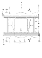
(自走式掃除ロボット1の説明)
図1に示すように、本実施形態の自走式掃除ロボット1は、構造物SPの対象平面SF上を走行するための移動機構を備えたロボット本体部2と、このロボット本体部2に設けられた一対の掃除部10,10と、を備えている。(Description of self-propelled cleaning robot 1)
As shown in FIG. 1, the self-propelled
(ロボット本体部2)
図1〜図3に示すように、ロボット本体部2は、掃除する対象である構造物SPの対象平面SFに沿って自走式掃除ロボット1を移動させるための移動機構4を備えている。(Robot body part 2)
As shown in FIGS. 1 to 3, the
この移動機構4は、一対の側方駆動輪4a,4aと、一つの中間駆動輪4bと、を備えている。具体的には、一対の側方駆動輪4a,4aと中間駆動輪4bとによって、平面視で三角形を形成するように配置されている(図1参照)。
このため、自走式掃除ロボット1を対象平面SF上に安定した状態で配置することができる。The moving
For this reason, the self-propelled
また、一対の側方駆動輪4a,4aには、回転軸周りの回転しかできない一般的な車輪を採用しているが、中間駆動輪4bにはオムニホイール(全方向移動車輪)を採用している。しかも、移動機構4の全ての駆動輪4a,4bはそれぞれ駆動モータに接続されており、各駆動モータが独立して各駆動輪4a,4bを駆動させることができるようになっている。そして、全ての駆動モータは、ロボット本体部2に設けられた制御部によってその回転速度が制御されている。
このため、制御部によって各駆動モータの回転速度を制御すれば、自走式掃除ロボット1を直線的に移動させたり、旋回移動させたりすることができる。The pair of
For this reason, if the rotation speed of each drive motor is controlled by the control unit, the self-propelled
以下では、ロボット本体部2において、一対の側方駆動輪4a,4aが設けられていない側面が存在する方向(図1では上下方向)を、自走式掃除ロボット1の前後方向という。 Hereinafter, in the
また、制御部によって各駆動モータの回転速度が制御され、自走式掃除ロボット1の移動が制御される。この自走式掃除ロボット1の移動経路は、制御部に移動経路を記憶させておきこの移動経路に沿って自動で対象平面SF上を移動するようにしてもよい。また、制御部に対して外部から信号を供給して移動を制御してもよい。例えば、リモコン等によって遠隔操作して自走式掃除ロボット1の移動を制御してもよい。 Moreover, the rotation speed of each drive motor is controlled by the control unit, and the movement of the self-propelled
さらに、駆動輪4は上記のごとき構成に限られず、自走式掃除ロボット1を直線的に移動させたり、旋回移動させたりすることができるように構成されていればよい。例えば、中間駆動輪4bであるオムニホイールを駆動輪とせず、一対の駆動輪4a,4aだけを駆動輪としてもよい。また、オムニホイールに代えて、中間駆動輪4bに受動車輪(キャスター)を採用してもよい。この場合でも、一対の駆動輪4a,4aの回転数を調整すれば、自走式掃除ロボット1の移動方向を自在に変更することができる。さらに、通常の車両と同様の構造としてもよい。つまり、車輪を4輪設けて、その前方(または後方)の2輪を操舵輪として他の車輪を駆動輪としたり、4輪駆動としてもよい。 Furthermore, the
(掃除部10)
図1〜図3に示すように、一対の掃除部10,10は、それぞれロボット本体部2の前方および後方に設けられている。なお、一対の掃除部10,10は実質的に同じ構造を有しているので、以下では、ロボット本体部2の前方(図2および図3では右側)に位置する掃除部10について説明する。(Cleaning unit 10)
As shown in FIGS. 1 to 3, the pair of cleaning
図1および図2に示すように、掃除部10は、フレーム11によってロボット本体部2に連結されている。この掃除部10は、ブラシ12を備えている。このブラシ12は、軸部12aと、この軸部12の外周面に設けられた一対の刷毛部12b,12bと、を備えている。 As shown in FIGS. 1 and 2, the
軸部12aは、その両端部が掃除部10のフレームに回転可能に支持されている。しかも、自走式掃除ロボット1を対象平面SF上に載せたときに、その軸方向が対象平面SFとほぼ平行となるように設けられている。 Both ends of the
一対の刷毛部12b,12bは、複数の刷毛を軸方向に沿って並べて形成されたものである。各刷毛部12bは、刷毛の位置が、軸部12aの軸方向に移動するに従って周方向に沿ってズレるように設けられている(図1および図4参照)。言い換えれば、各刷毛部12bは、軸部12aの側面に螺旋状に形成されている。しかも、一対の刷毛部12b,12bで二重螺旋を形成するように配設されている。つまり、軸部12aの軸方向と直交する断面において、一対の刷毛部12b,12bの各刷毛が互いに180度回転した位置となるように、一対の刷毛部12b,12bが形成されているのである(図3参照)。 The pair of
また、図4に示すように、掃除部10は、ブラシ12の軸部12aを軸周りに回転させるブラシ駆動部13を備えている。具体的には、このブラシ駆動部13は、ブラシ駆動モータ13aを備えており、ブラシ駆動モータ13aの主軸がブラシ12の軸部12aの端部とベルトプーリ機構13bによって連結されている。そして、ブラシ駆動モータ13aは、制御部によってその作動状態が制御されている。
このため、ブラシ駆動モータ13aを作動させれば、その駆動力がベルトプーリ機構13bを介してブラシ12の軸部12aに伝達され、ブラシ12を回転させることができる。Moreover, as shown in FIG. 4, the cleaning
Therefore, when the
なお、ブラシ駆動モータ13aは、自走式掃除ロボット1を対象平面SFに載せた状態において、ブラシ12の刷毛部12bの先端部が、ロボット本体2から離間しつつ対象平面SFに接近する方向に回転するように制御されている(図2および図3の矢印の方向)。つまり、図2および図3であれば、ロボット本体2の前面側(右側)に位置する掃除部10のブラシ12は反時計まわりに回転し、ロボット本体2の後面側(左側)に位置する掃除部10のブラシ12は時計まわりに回転するように、ブラシ駆動モータ13aの作動が制御されている。 The
そして、図3に示すように、掃除部10は、ブラシ12とロボット本体部2の前面との間に気流形成カバー15を備えている。この気流形成カバー15は、ブラシ12の軸部12aの軸方向に沿って延びた、ブラシ12の一部を覆うように設けられた部材である。具体的には、気流形成カバー15は、ブラシ12におけるロボット本体2側の部分からブラシ12の上方の部分(つまり対象平面SFと逆側に位置する部分)を覆うように設けられている。そして、この気流形成カバー15は、ブラシ12側の面がブラシ12側から凹んだ面となるように形成されている。具体的には、ブラシ12側に開口を有する、断面視略C字状または断面視略逆くの字状に形成されている。 As shown in FIG. 3, the
以上のごとき構成であるので、本実施形態の自走式掃除ロボット1を使用すれば、以下のごとく対象平面SFを掃除することができる。 Since it is the above structure, if the self-propelled
まず、本実施形態の自走式掃除ロボット1を対象平面SFに載せる。すると、全ての駆動輪4が対象平面SFに接触した状態で配置される(図2および図3参照)。 First, the self-propelled
この状態で、一対の掃除部10,10のブラシ駆動部13を作動させると、ブラシ12が回転する。すると、各ブラシ12の刷毛部12bは、その先端部が対象平面SFを掃くように移動する。 If the
この状態で移動機構4によって自走式掃除ロボット1を移動させれば、対象平面SF上を、順次、ブラシ12の刷毛部12bによって掃くことができる。すると、自走式掃除ロボット1の移動に伴って、対象平面SF上を順次掃除することができる(図7参照)。 If the self-propelled
ここで、本実施形態の自走式掃除ロボット1では、ブラシ12の刷毛部12bによって対象平面SFを掃くだけであり、掃いた埃などを回収する機構を設けていない。このため、ブラシ12の刷毛部12bが接触した部分(掃き出し部)の埃などは対象平面SFから浮き上がるだけである。 Here, in the self-propelled
しかし、掃除部10は、ブラシ12の刷毛部12bの先端部がロボット本体2から離間しつつ対象平面SFに接近する方向に回転されている。すると、ブラシ12の軸部12aに対して対象平面SF側(下方)では、刷毛部12bの移動に伴ってロボット本体2から外方に向かう空気の流れ(吹き出し流)が発生する。このため、対象平面SFから浮き上がった埃などは、この吹き出し流によって掃き出し部から外方に向かって吹き飛ばされるので、掃き出し部の表面は埃などが少ない状態とすることができる。 However, the
一方、ブラシ12の軸部12aに対して上方では、ロボット本体2に向かう空気の流れが発生する。すると、この空気の流れは、気流形成カバー15によって、ロボット本体2から外方に向かう空気の流れに返還される(図3の矢印a参照)。つまり、気流形成カバー15によって、吹き出し流が強化される。すると、対象平面SFから浮き上がった埃などは、この吹き出し流によって掃き出し部からより遠くまで吹き飛ばされるので、掃き出し部の近傍が吹き飛ばされた埃などによって汚れることを抑制することができる。 On the other hand, an air flow toward the
なお、吹き飛ばされた埃などはやがて落下するが、吹き出し流によって埃は拡散されているので、各場所にはわずかの埃などしか落ちない。しかも、吹き飛ばされた埃などは風等によってさらに拡散されるので、埃などを飛散した場合でも、周辺の汚れは、ブラシ12の刷毛部12bが接触する前の掃き出し部よりも汚れが少ない状態となる。
したがって、上記のように埃などを吹き飛ばすことによって他の部分が汚れることを防ぐことができる。すると、対象平面SFから掃いて除去された埃を集めることなく、対象平面SFを掃除することができる。そして、集塵する部分をロボット本体2に設ける必要がないので、ロボット本体2を大型化することない。しかも、埃などを吸引する必要がないので、自走式掃除ロボット1を作動させるための電力消費を少なくできるから、非常に広い場所の掃除を連続して実施することができる。Note that the dust blown off will eventually fall, but since the dust is diffused by the blowout flow, only a small amount of dust will fall in each place. Moreover, since the dust blown off is further diffused by the wind or the like, even when the dust is scattered, the surrounding dirt is in a state where the dirt is less than that of the sweeping part before the
Therefore, it is possible to prevent other parts from becoming dirty by blowing off dust and the like as described above. Then, the target plane SF can be cleaned without collecting dust removed by sweeping from the target plane SF. And since it is not necessary to provide the robot
例えば、対象平面SFが砂漠や火山灰が降灰する地域などに設置された大規模太陽光発電施設の太陽電池アレイの表面の場合には、表面に堆積する埃などは細かい砂などである。しかも、設置された場所では、発電の妨げとなる日陰ができることを防止するため、周囲に障害となる建物等を配置しないことが通常である。このため、大規模太陽光発電施設の周囲では、風が強く吹いている。したがって、太陽電池アレイの表面の砂などを本実施形態の自走式掃除ロボット1で掃除して、砂や灰などを太陽電池アレイの表面から一旦引き剥がして吹き飛ばしてやれば、風等の作用も手伝って、砂などが遠くまで拡散し、太陽電池アレイの表面を順次埃が少ない状態とすることができる。
そして、自走式掃除ロボット1が掃除をするための消費電力を少なくできるから長時間連続して作業を実行することができる。したがって、上記のごとき大規模太陽光発電施設の太陽電池アレイの掃除を効率よく実施することができる。For example, when the target plane SF is the surface of a solar cell array of a large-scale photovoltaic power generation facility installed in a desert or an area where volcanic ash falls, dust accumulated on the surface is fine sand or the like. In addition, in order to prevent the shade that hinders power generation from occurring, it is normal that no obstructing buildings or the like are arranged around the place where the power is installed. For this reason, the wind is blowing strongly around the large-scale photovoltaic power generation facility. Therefore, if sand or the like on the surface of the solar cell array is cleaned by the self-propelled
And since self-propelled
なお、ブラシ12の回転方向は上記のごとき方向に回転させると、埃などを除去する効率を高くすることができるが、ブラシ12の回転方向は逆方向に回転させてもよい。この場合、ブラシ12の軸部12aに対して下方では、ロボット本体2に向かう空気の流れが発生するので、ブラシ12が浮き上がらせた埃などは気流形成カバー15内に流入することになる。しかし、ブラシ12の軸部12aに対して上方では、ロボット本体2から外方に向かう空気の流れが発生するため、最終的には、平面から浮き上がった埃を外方に飛散させることができる。 Note that, when the rotation direction of the
また、図3では、気流形成カバー15は、その先端がブラシ12の軸の上方までしか延びていないが、気流形成カバー15の先端の位置はとくに限定されない。しかし、気流形成カバー15によってブラシ12の上部が覆われている領域は広いほど、ブラシ12の回転による気流形成効果を高めることができる。したがって、気流形成カバー15は、ブラシ12の上部全体を覆うように設けられている方が好ましい(図6参照)。例えば、図6に示すように、気流形成カバー15の先端を、ブラシ12の先端が最もロボット本体2から離れる位置まで延ばしてもよい。 In FIG. 3, the tip of the
(ブレード12f)
さらに、ブラシ12の軸部12aには、刷毛部12bとは別にブレード12fを設けてもよい(図6参照)。ブレード12fを設ければ、刷毛部12bだけでなくブレード12fによっても気流を形成することができるので、ブラシ12の回転により形成される気流を強くすることができる。なお、ブレード12fはブラシ12の刷毛部12bと干渉しないように設けることが望ましいので、上記例のように、ブラシ12の刷毛部12bが螺旋状に設けられている場合には、ブレード12fも螺旋状に設けることが望ましい。
また、ブレード12fの形状はとくに限定されず、ブラシ12の回転によって気流を形成できる形状であればよい。例えば、板状の部材を軸部12aに立設してブレード12fを形成することができる。この場合、板状の部材の長さ(軸部12aの半径方向の長さ)はとくに限定されないが、刷毛部12bによる掃除の邪魔にならない程度で長いものが望ましい。例えば、刷毛部12bの長さの半分程度とすれば十分な気流形成効果を得ることができる。
さらに、ブレード12fを設ける位置や数はとくに限定されない。例えば、図6に示すように、軸部12aの周方向において、一対の刷毛部12b,12bの中間に一つずつ(つまり2つ)設ければ、ブラシ12の重量の増加を防ぎつつ、気流形成の効果を十分に高めることができる。(
Further, a
The shape of the
Furthermore, the position and number of the
(空気供給手段20)
また、ブラシ12に向かって空気を吹き出す空気供給手段20を設けてもよい。この場合、空気供給手段20から供給される空気の流れをブラシ12の刷毛部12bに当てることができる。すると、この空気の流れによってブラシ12の刷毛部12bに付着した埃などを除去することができるので、ブラシ12の刷毛部12bをきれいな状態に維持することができる。すると、ブラシ12の刷毛部12bによる対象平面SFを掃除する効果の低下を防止することができる。(Air supply means 20)
Further, an air supply means 20 that blows air toward the
空気供給手段20の構成はとくに限定されないが、例えば、気流形成カバー15の内壁に複数のファン21を設けて上述したような空気の流れを形成することができる。また、複数のファン21に代えて空気排出口を設けて、この空気排出口にダクトを介してブロアなどの空気供給手段から空気を供給するようにしてもよい。 The configuration of the air supply means 20 is not particularly limited. For example, a plurality of
また、ブロアなどの空気供給手段から空気を供給する場合には、ブラシ12の軸部12aから空気を刷毛部12bに向かって吹き出すようにしてもよい。例えば、軸部12aとして、中空なパイプを採用し、その側面に吹き出し口を設けておく。すると、軸部12aの軸端からパイプ内に空気を供給すれば、吹き出し口から空気を吹き出すことができる。すると、ブラシ12の一対の刷毛部12b,12bに対して、確実に空気を当てることができるので、刷毛部12bを掃除する効果を高めることができる。 Moreover, when supplying air from air supply means, such as a blower, you may make it blow off air from the
(しごき部材15b)
刷毛部12bを掃除する方法として、ブラシ12の刷毛部12bをしごくような部材を設けてもよい。例えば、図6に示すように、気流形成カバー15の内側にしごき部材15bを設けておけば、ブラシ12が回転すると、1回転する間に、必ず刷毛部12bはしごき部材15bと接触するので、刷毛部12bに付着した砂などを落とすことができる。なお、しごき部材15bを設ける位置や形状、設置方法はとくに限定されないが、しごき部材15bを設けたことによる気流形成カバー15による気流形成効果が低下することを防ぐ上では、しごき部材15bは、しごき部材15bと気流形成カバー15の内面との間に隙間が形成されるように設置することが望ましい。例えば、棒状のしごき部材15bを設ける場合であれば、ブラケットなどによってしごき部材15bの両端または中間を気流形成カバー15の内面に連結する。すると、ブラケットを設けた位置以外は、しごき部材15bと気流形成カバー15の内面との間に隙間が形成されるので、しごき部材15bを設けたことによる気流形成カバー15による気流形成効果が低下することを防ぐことができる。(Squeezing
As a method for cleaning the
(刷毛部12bについて)
なお、一対の刷毛部12b,12bを構成する刷毛の長さはとくに限定されない。自走式掃除ロボット1を対象平面SF上に載せたときに、刷毛の先端部が対象平面SFに接触する程度の長さに形成されていればよい。例えば、自走式掃除ロボット1を対象平面上に載せたときに、対象平面SFから軸部12aの外周面までの距離が37mmであれば、刷毛の長さは45〜47mm程度が好ましい。ただし、これは刷毛の剛性等、ロボットの他のパラメータに応じて決定されるものであり、上述の寸法に限定されるものでないことはいうまでもない。(About the
In addition, the length of the brush which comprises a pair of
また、各刷毛部12bは螺旋状に配置しなくてもよい。例えば、刷毛を軸部12bの軸方向に沿って並ぶように配置してもよく、とくに限定されない。 Moreover, each
(ロボット本体部2の他の例)
図7に示すように、上述した自走式掃除ロボット1は、複数の太陽電池モジュールからなる太陽電池アレイのように、複数の構造体をからなる構造物SPにおいて、各構造体の表面を順次掃除する場合に適している。(Another example of the robot body 2)
As shown in FIG. 7, the self-propelled
一方、複数の太陽電池モジュールからなる太陽電池アレイのように、構造物SPを構成する複数の構造体の表面を同時に掃除することは、上述した自走式掃除ロボット1でも可能であるが、自走式掃除ロボット1を以下のような構造とすれば、より掃除が容易になる。
なお、以下の自走式掃除ロボット1B〜1Dが掃除する構造物SPの構造はとくに限定されない。しかし、太陽電池モジュール等の構造体を複数格子状に並べて形成された太陽電池アレイ等の構造物SPであって、上下方向よりも横方向に長くなるように形成された構造物SPに適している。以下では、構造物SPの上下方向(つまり長さが短い方向)を、構造物SPの短軸方向という。
また、以下の自走式掃除ロボット1B〜1Dも、基本的な構造は、上述した自走式掃除ロボット1と実質的に同等であるので、以下では、自走式掃除ロボット1と異なる構成を有する部分についてのみ説明する。On the other hand, the above-described self-propelled
In addition, the structure of structure SP which the following self-propelled
In addition, since the basic structure of the following self-propelled
(自走式掃除ロボット1B)
図8に示すように、自走式掃除ロボット1Bは、自走式掃除ロボット1に対して、その幅(つまり掃除部10におけるブラシ12の軸方向)を長くしたものである。具体的には、ブラシ12の軸方向の長さが、構造物SPの短軸方向の長さAL(以下単に構造物SPの長さALという)よりも長くなるようにしたものである。つまり、ブラシ12の軸方向の長さを、ブラシ12の刷毛部12bが、構造物SPの複数の構造体全体と接触する程度の長さとしている。
かかる構造の自走式掃除ロボット1Bの場合、自走式掃除ロボット1を対象平面SF上に載せて、ブラシ12の軸方向を構造物SPの短軸方向と一致させる。この状態から移動機構4の駆動輪4aを作動させれば、自走式掃除ロボット1Bを構造物SPの幅方向(図8では左右方向)に移動させることができるので、複数の構造体を同時に掃除することができる。(Self-propelled
As shown in FIG. 8, the self-propelled
In the case of the self-propelled
(自走式掃除ロボット1C)
図9に示す自走式掃除ロボット1Cは、上述した自走式掃除ロボット1Bにエッジローラ4eを設けたものであり、その他の構成は自走式掃除ロボット1Bと実質的に同様の構成を有するものである。(Self-propelled
A self-propelled
エッジローラ4eは、自走式掃除ロボット1Cを構造物SP上に配置したときに、構造物SPの構造体の上端縁と接触する位置に設けられている。つまり、自走式掃除ロボット1Cは、エッジローラ4eによって構造物SPに引っ掛かった状態となっている。このため、自走式掃除ロボット1Cは、自走式掃除ロボット1Bに比べて、構造物SPの対象平面SF上に安定した状態で配置しておくことができる。言い換えれば、自走式掃除ロボット1Cは、自走式掃除ロボット1Bに比べて、構造物SPの対象平面SFから落ちることを防ぐことができる。 The
しかも、エッジローラ4eは、その回転軸が対象平面SFと平行になるように設けられており、自走式掃除ロボット1Cが構造物SPの幅方向に移動した際に、構造物SPの構造体の上端縁上を転動できるようになっている。このため、エッジローラ4eを設けても、自走式掃除ロボット1Cは構造物SPの対象平面SF上をスムースに移動できる。 Moreover, the
(自走式掃除ロボット1D)
図10に示す自走式掃除ロボット1Dは、上述した自走式掃除ロボット1Bのロボット本体部2に一対の移動脚2cf,2cfを設け、一対の移動脚2cf,2cfの駆動輪4fによって駆動するようにしたものであり、その他の構成は自走式掃除ロボット1Bと実質的に同様の構成を有するものである。(Self-propelled
A self-propelled
一対の移動脚2cf,2cfは、ロボット本体部2の幅方向の両端に設けられている。この一対の移動脚2cf,2cfは、構造物SPを跨ぐように自走式掃除ロボット1Dを配置すると、ロボット本体部2(言い換えれば、掃除部10におけるブラシ12の軸方向)が構造物SPの対象平面SFと平行となり、しかも、掃除部10のブラシ12の刷毛部12bが構造物SPの対象平面SFと接触するように、各移動脚2cfの長さが調整されている。
また、一対の移動脚2cf,2cfは、その下端に駆動輪4fを備えている。この駆動輪4fは、ブラシ12の軸方向と直交する方向に転動するように設けられている。
このため、構造物SPを跨ぐように一対の移動脚2cf,2cfを備えた自走式掃除ロボット1Dを配置し、かつ、ブラシ12の軸方向が構造物SPの短軸方向と一致するように配置すれば、構造物SPの対象平面SFに沿って、自走式掃除ロボット1Dを構造物SPの幅方向(図8では左右方向)に移動させることができ、複数の構造体を同時に掃除することができる。The pair of moving legs 2cf, 2cf are provided at both ends in the width direction of the
The pair of moving legs 2cf, 2cf includes a
For this reason, the self-propelled
また、上記のごとき自走式掃除ロボット1Dでは、ロボット本体部2に対して、掃除部10が移動できるようになっていてもよい。例えば、掃除部10の両端部(図10(B)では左右方向の端部)を、エアシリンダやネジ機構などの昇降部2sbを介して、ロボット本体部2に連結する。すると、構造物SPを跨ぐように一対の移動脚2cf,2cfを備えた自走式掃除ロボット1Cを配置して、昇降部2sbを作動させれば、構造物SPの対象平面SFに対して掃除部10を接近離間させることができる。この場合、構造物SPの設置状態によって、構造物SPの対象平面SFの高さや傾きが異なっていても、昇降部2sbの作動を調整すれば、掃除部10のブラシ12の刷毛部12bと構造物SPの対象平面SFとの接触状態を掃除に適した状態とすることができる。 In the self-propelled
なお、ブラシ12の刷毛部12bと構造物SPの対象平面SFとの接触状態(つまり、昇降部2sbの作動量)は、接触センサーや非接触センサーなどによって掃除部10と対象平面SFとの距離を測定し、その測定値に基づいて昇降部2sbの作動を制御してもよい。 The contact state between the
また、昇降部2sbとして、掃除部10を吊り上げる機能は有するが、吊り上げを解除すると掃除部10の自重で下降するようなものを使用してもよい。この場合には、掃除部10の両端に一対の従動輪10b,10bを設けておけば、一対の従動輪10b,10bの両方が構造物SPの対象平面SFと接触するまで、掃除部10が下降する。したがって、特別なセンサーがなくても、ブラシ12の刷毛部12bと構造物SPの対象平面SFとが所定の接触状態となるようにすることができる。 Moreover, although it has the function which lifts the
さらに、掃除部10が下降した状態において、掃除部10を所定の付勢力で構造物SPの対象平面SFに押し付けるような機構を設けてもよい。例えば、掃除部10とロボット本体部2との間に、バネなどの付勢手段を設けてもよい。この場合、付勢手段の付勢力によって構造物SPの対象平面SFに一対の従動輪10b,10bを接触させた状態に維持できるので、掃除部10(つまりブラシ12の刷毛部12b)は対象平面SFとの距離をほぼ一定に保って移動する。つまり、段差などがあっても、ブラシ12の刷毛部12bと構造物SPの対象平面SFとの接触状態をほぼ一定に保ちながら掃除部10を対象平面SFに沿って移動させることができるので、安定した掃除を実施することができる。 Furthermore, in a state where the
本発明の自走式掃除ロボットは、大規模な太陽光発電施設の太陽電池アレイや、太陽熱発電施設の集光ミラー、太陽熱温水器における受光面などの掃除するロボットとして適している。 The self-propelled cleaning robot of the present invention is suitable as a robot for cleaning a solar cell array of a large-scale photovoltaic power generation facility, a condensing mirror of a solar thermal power generation facility, a light receiving surface in a solar water heater, and the like.
1 自走式掃除ロボット
2 ロボット本体部
10 掃除部
12 ブラシ
12a 軸部
12b 刷毛部
15 気流形成カバー
SP 構造物
SF 対象平面DESCRIPTION OF
Claims (6)
自走のための移動手段が設けられたロボット本体と、
該ロボット本体の側面に設けられた掃除部と、を備えており、
該掃除部が、
軸部と該軸部に設けられた刷毛部とからなる回転可能なブラシと、
前記平面を掃除する際に、前記ブラシにおける前記ロボット本体側かつ前記平面と逆側に位置する部分を覆うように設けられた気流形成カバーと、を備えている
ことを特徴とする自走式掃除ロボット。A robot that runs on a structure having a plane installed outdoors and cleans the plane of the structure,
A robot body provided with a moving means for self-running;
A cleaning unit provided on a side surface of the robot body,
The cleaning part
A rotatable brush comprising a shaft portion and a brush portion provided on the shaft portion;
A self-propelled cleaning comprising: an airflow forming cover provided so as to cover a portion of the brush located on the side of the robot main body and on the opposite side of the plane when the plane is cleaned; robot.
前記平面を掃除する際に、その先端部が、前記ロボット本体から離間しつつ前記平面に接近する方向に回転するように制御されている
ことを特徴とする請求項1記載の自走式掃除ロボット。The brush
2. The self-propelled cleaning robot according to claim 1, wherein when the plane is cleaned, a tip portion thereof is controlled to rotate in a direction approaching the plane while being separated from the robot body. .
前記ブラシに向かって空気を吹き出す空気供給手段を備えており、
該空気供給手段の空気吹き出し口が、
前記気流形成カバーの内面に設けられている
ことを特徴とする請求項1または2記載の自走式掃除ロボット。The cleaning unit is
Air supply means for blowing air toward the brush,
An air outlet of the air supply means is
The self-propelled cleaning robot according to claim 1, wherein the self-propelled cleaning robot is provided on an inner surface of the airflow forming cover.
自走のための移動手段が設けられたロボット本体と、
該ロボット本体の側面に設けられた掃除部と、を備えており、
該掃除部が、
軸部と該軸部に設けられた刷毛部とからなる回転可能なブラシと、
該ブラシに向かいかつロボット本体から離れる方向に向かって空気を吹き出す空気供給手段と、を備えており、
前記ブラシは、
前記平面を掃除する際に、その先端部が、前記ロボット本体から離間しつつ前記平面に接近する方向に回転するように制御されている
ことを特徴とする自走式掃除ロボット。A robot that runs on a structure having a plane installed outdoors and cleans the plane of the structure,
A robot body provided with a moving means for self-running;
A cleaning unit provided on a side surface of the robot body,
The cleaning part
A rotatable brush comprising a shaft portion and a brush portion provided on the shaft portion;
Air supply means for blowing air toward the brush and away from the robot body, and
The brush
A self-propelled cleaning robot characterized in that, when cleaning the plane, the tip thereof is controlled to rotate in a direction approaching the plane while being separated from the robot body.
前記平面を掃除する際に、前記ブラシにおける前記ロボット本体側かつ前記平面と逆側に位置する部分を覆うように設けられた気流形成カバーを備えており、
前記気流形成カバーの内面に、
前記空気供給手段の空気吹き出し口が設けられている
ことを特徴とする請求項4記載の自走式掃除ロボット。The cleaning unit is
When cleaning the plane, it comprises an airflow forming cover provided so as to cover a portion of the brush located on the robot body side and the opposite side of the plane,
On the inner surface of the airflow forming cover,
The self-propelled cleaning robot according to claim 4, wherein an air outlet of the air supply means is provided.
前記軸部が中空なパイプによって形成されており、
該軸部の側面に空気を吹き出す吹き出し口が設けられており、
前記掃除部が、
前記ブラシの軸部に空気を供給する空気供給手段が設けられている
ことを特徴とする請求項1乃至5のいずれかに記載の自走式掃除ロボット。The brush
The shaft is formed by a hollow pipe;
A blowout port for blowing out air is provided on the side surface of the shaft part,
The cleaning unit is
The self-propelled cleaning robot according to any one of claims 1 to 5, further comprising air supply means for supplying air to the shaft portion of the brush.
Priority Applications (1)
| Application Number | Priority Date | Filing Date | Title |
|---|---|---|---|
| JP2014521762A JP5686270B2 (en) | 2012-12-25 | 2013-12-25 | Self-propelled cleaning robot |
Applications Claiming Priority (4)
| Application Number | Priority Date | Filing Date | Title |
|---|---|---|---|
| JP2012281077 | 2012-12-25 | ||
| JP2012281077 | 2012-12-25 | ||
| PCT/JP2013/007560 WO2014103290A1 (en) | 2012-12-25 | 2013-12-25 | Autonomous-travel cleaning robot |
| JP2014521762A JP5686270B2 (en) | 2012-12-25 | 2013-12-25 | Self-propelled cleaning robot |
Publications (2)
| Publication Number | Publication Date |
|---|---|
| JP5686270B2 true JP5686270B2 (en) | 2015-03-18 |
| JPWO2014103290A1 JPWO2014103290A1 (en) | 2017-01-12 |
Family
ID=51020408
Family Applications (1)
| Application Number | Title | Priority Date | Filing Date |
|---|---|---|---|
| JP2014521762A Active JP5686270B2 (en) | 2012-12-25 | 2013-12-25 | Self-propelled cleaning robot |
Country Status (6)
| Country | Link |
|---|---|
| US (1) | US20150236640A1 (en) |
| EP (1) | EP2902120B1 (en) |
| JP (1) | JP5686270B2 (en) |
| IL (1) | IL239619B (en) |
| IN (1) | IN2015DN02486A (en) |
| WO (1) | WO2014103290A1 (en) |
Cited By (3)
| Publication number | Priority date | Publication date | Assignee | Title |
|---|---|---|---|---|
| JP2016209801A (en) * | 2015-05-07 | 2016-12-15 | 和也 石坂 | Drone-incorporated cleaning device and cleaning unit of the same |
| CN107669206A (en) * | 2017-09-28 | 2018-02-09 | 佛山市南方数据科学研究院 | A kind of robot based on cloud service |
| KR20180118025A (en) * | 2017-04-20 | 2018-10-30 | 한국교통대학교산학협력단 | Solar power plant cleaning device using the ultrasonic technology |
Families Citing this family (24)
| Publication number | Priority date | Publication date | Assignee | Title |
|---|---|---|---|---|
| IN2015DN02484A (en) * | 2012-12-25 | 2015-09-11 | Miraikikai Inc | |
| WO2016016914A1 (en) * | 2014-07-31 | 2016-02-04 | 株式会社 スカイロボット | Cleaning device for solar photovoltaic panel |
| WO2016172810A1 (en) * | 2015-04-27 | 2016-11-03 | 张意铃 | Thermal-infrared detection system applied to photovoltaic module fault detection |
| KR101718365B1 (en) * | 2015-06-24 | 2017-03-22 | 주식회사 케이디파워 | Photovoltaic power generation |
| KR101678443B1 (en) | 2015-09-23 | 2016-12-06 | 엘지전자 주식회사 | Robot Cleaner |
| CN107198499B (en) * | 2016-03-18 | 2021-03-05 | 松下电器(美国)知识产权公司 | Autonomous moving apparatus, autonomous moving method, and autonomous moving system |
| JP6913387B2 (en) * | 2016-03-31 | 2021-08-04 | 株式会社未来機械 | Work robot and edge detector |
| JP2017190631A (en) * | 2016-04-14 | 2017-10-19 | 株式会社三和綜合土木 | Cleaning apparatus and roof cleaning method and primer processing method |
| DE102016110913A1 (en) * | 2016-06-14 | 2017-12-14 | Götz Siegmann | Paneelreinigungsvorrichtung |
| JP2018015686A (en) * | 2016-07-26 | 2018-02-01 | 株式会社ニクニ | Water tank washing device and water tank washing method |
| US11201583B2 (en) | 2017-01-26 | 2021-12-14 | Evermore United S.A. | Waterless cleaning system and method for solar trackers using an autonomous robot |
| US10498287B2 (en) | 2017-01-26 | 2019-12-03 | Evermore United S.A. | Waterless cleaning system and method for solar trackers using an autonomous robot |
| US10797636B2 (en) | 2017-01-26 | 2020-10-06 | Evermore United S.A. | Waterless cleaning system and method for solar trackers using an autonomous robot |
| US10498288B2 (en) | 2017-01-26 | 2019-12-03 | Evermore United S.A. | Waterless cleaning system and method for solar trackers using an autonomous robot |
| US11357512B2 (en) | 2017-05-12 | 2022-06-14 | Robert Fishel | Mechanism and device for left atrial appendage occlusion with electrical isolation |
| CN107659250B (en) * | 2017-09-20 | 2019-05-14 | 镇江倍斯特曼新材料研究有限公司 | A kind of fixed device of solar generating of self-clean type |
| CN107769717B (en) * | 2017-10-20 | 2019-04-30 | 中车青岛四方车辆研究所有限公司 | Robot cleans dust collect plant |
| KR102051049B1 (en) * | 2017-11-20 | 2019-12-02 | 유진기술 주식회사 | Solar panel cleaning robot system based on self-driving multi agent |
| US10277163B1 (en) | 2018-07-11 | 2019-04-30 | Evermore United S.A. | Magnetic parking for robotic cleaner on a solar panel |
| US10873291B1 (en) * | 2018-11-06 | 2020-12-22 | Mary Ethel Parker | Methods for cleaning photovoltaic panels |
| CN109431386A (en) * | 2018-11-21 | 2019-03-08 | 合肥泽尼特新能源有限公司 | A kind of new energy floor cleaning apparatus |
| CN109591029A (en) * | 2018-12-30 | 2019-04-09 | 周帆 | A kind of house robot with photovoltaic power generation function |
| CN114287847B (en) * | 2021-12-28 | 2023-01-17 | 广州市宇明机电设备有限公司 | Pneumatic type factory building roof cleaning device |
| CN114558808A (en) * | 2022-03-01 | 2022-05-31 | 北京天骥空间科技有限公司 | Photovoltaic power station cleaning robot and using method |
Citations (4)
| Publication number | Priority date | Publication date | Assignee | Title |
|---|---|---|---|---|
| JPH10202563A (en) * | 1997-01-17 | 1998-08-04 | Mitsui Eng & Shipbuild Co Ltd | Wall surface cleaning device |
| JP2002273351A (en) * | 2001-03-19 | 2002-09-24 | Hino Jushi:Kk | Method and apparatus for cleaning outer face of solar cell panel |
| JP2004186632A (en) * | 2002-12-06 | 2004-07-02 | Yanmar Agricult Equip Co Ltd | Solar battery panel apparatus |
| JP4808803B2 (en) * | 2009-08-18 | 2011-11-02 | 株式会社旭メカニカル | Solar panel cleaning equipment |
Family Cites Families (18)
| Publication number | Priority date | Publication date | Assignee | Title |
|---|---|---|---|---|
| US2331692A (en) * | 1940-10-15 | 1943-10-12 | Hilland G Hunt | Vacuum cleaner |
| US4594749A (en) * | 1984-11-13 | 1986-06-17 | Waterman Dale G | Vacuum cleaner with air jet assist |
| US5045118A (en) * | 1990-05-04 | 1991-09-03 | Tennant Company | Method of removing debris and dust from a carpet |
| US5239721A (en) * | 1991-07-17 | 1993-08-31 | Royal Appliance Mfg. Co. | Planetary gear system for sweeper brush roll |
| JPH05169038A (en) * | 1991-12-17 | 1993-07-09 | Honda Motor Co Ltd | Wiper |
| JPH06324610A (en) * | 1993-05-17 | 1994-11-25 | Minolta Camera Co Ltd | Brush cleaning device |
| CA2251295C (en) * | 1998-01-27 | 2002-08-20 | Sharp Kabushiki Kaisha | Electric vacuum cleaner |
| US5991953A (en) * | 1998-08-25 | 1999-11-30 | Tennant Company | Sweeping machine with multiple position front flap |
| KR20030082040A (en) * | 2002-04-16 | 2003-10-22 | 삼성광주전자 주식회사 | Robot cleaner |
| US20050209736A1 (en) * | 2002-11-13 | 2005-09-22 | Figla Co., Ltd. | Self-propelled working robot |
| JP2004166968A (en) | 2002-11-20 | 2004-06-17 | Zojirushi Corp | Self-propelled cleaning robot |
| US7617557B2 (en) * | 2004-04-02 | 2009-11-17 | Royal Appliance Mfg. Co. | Powered cleaning appliance |
| JP4991718B2 (en) * | 2005-07-20 | 2012-08-01 | オプティマス ライセンシング アクチェンゲゼルシャフト | Robot floor cleaning machine with aseptic disposable cartridge |
| KR101300492B1 (en) * | 2005-12-02 | 2013-09-02 | 아이로보트 코퍼레이션 | Coverage robot mobility |
| EP2343003A1 (en) * | 2010-01-07 | 2011-07-13 | Koninklijke Philips Electronics N.V. | Cleaning device with spraying means and rotatable brush |
| EP2366964A1 (en) * | 2010-03-15 | 2011-09-21 | Sener Ingenieria Y Sistemas, S.A. | Solar field cleaning system and cleaning method used by said system |
| KR101573742B1 (en) * | 2010-10-25 | 2015-12-07 | 삼성전자주식회사 | Autonomous cleaning device |
| US20140182079A1 (en) * | 2011-08-23 | 2014-07-03 | Koninklijke Philips N.V. | Cleaning device for cleaning a surface comprising a brush and a squeegee element |
-
2013
- 2013-12-25 WO PCT/JP2013/007560 patent/WO2014103290A1/en active Application Filing
- 2013-12-25 EP EP13867338.9A patent/EP2902120B1/en active Active
- 2013-12-25 JP JP2014521762A patent/JP5686270B2/en active Active
- 2013-12-25 US US14/430,775 patent/US20150236640A1/en not_active Abandoned
- 2013-12-25 IN IN2486DEN2015 patent/IN2015DN02486A/en unknown
-
2015
- 2015-06-24 IL IL239619A patent/IL239619B/en active IP Right Grant
Patent Citations (4)
| Publication number | Priority date | Publication date | Assignee | Title |
|---|---|---|---|---|
| JPH10202563A (en) * | 1997-01-17 | 1998-08-04 | Mitsui Eng & Shipbuild Co Ltd | Wall surface cleaning device |
| JP2002273351A (en) * | 2001-03-19 | 2002-09-24 | Hino Jushi:Kk | Method and apparatus for cleaning outer face of solar cell panel |
| JP2004186632A (en) * | 2002-12-06 | 2004-07-02 | Yanmar Agricult Equip Co Ltd | Solar battery panel apparatus |
| JP4808803B2 (en) * | 2009-08-18 | 2011-11-02 | 株式会社旭メカニカル | Solar panel cleaning equipment |
Cited By (6)
| Publication number | Priority date | Publication date | Assignee | Title |
|---|---|---|---|---|
| JP2016209801A (en) * | 2015-05-07 | 2016-12-15 | 和也 石坂 | Drone-incorporated cleaning device and cleaning unit of the same |
| KR20180118025A (en) * | 2017-04-20 | 2018-10-30 | 한국교통대학교산학협력단 | Solar power plant cleaning device using the ultrasonic technology |
| KR101969090B1 (en) * | 2017-04-20 | 2019-04-15 | 한국교통대학교산학협력단 | Solar power plant cleaning device using the ultrasonic technology |
| KR20190039919A (en) * | 2017-04-20 | 2019-04-16 | 한국교통대학교산학협력단 | Solar panel cleaning device with brush that containing water supplying device |
| KR102038840B1 (en) * | 2017-04-20 | 2019-10-31 | 한국교통대학교산학협력단 | Solar panel cleaning device with brush that containing water supplying device |
| CN107669206A (en) * | 2017-09-28 | 2018-02-09 | 佛山市南方数据科学研究院 | A kind of robot based on cloud service |
Also Published As
| Publication number | Publication date |
|---|---|
| EP2902120B1 (en) | 2020-07-15 |
| US20150236640A1 (en) | 2015-08-20 |
| JPWO2014103290A1 (en) | 2017-01-12 |
| EP2902120A1 (en) | 2015-08-05 |
| EP2902120A4 (en) | 2016-08-17 |
| IL239619A0 (en) | 2015-08-31 |
| IL239619B (en) | 2020-07-30 |
| IN2015DN02486A (en) | 2015-09-11 |
| WO2014103290A1 (en) | 2014-07-03 |
Similar Documents
| Publication | Publication Date | Title |
|---|---|---|
| JP5686270B2 (en) | Self-propelled cleaning robot | |
| JP5686272B2 (en) | Self-propelled cleaning robot | |
| JP5686271B2 (en) | Self-propelled cleaning robot | |
| JP6404348B2 (en) | Self-propelled robot | |
| CN105881555B (en) | Photovoltaic plant sweeping robot and its working method based on the direct dedusting of blower | |
| JP7359450B2 (en) | cleaning robot | |
| Patil et al. | A review on cleaning mechanism of solar photovoltaic panel | |
| KR101676728B1 (en) | Large scale- solar cell cleaning robot for preventing snow accumulation tracking on rail of solar cell | |
| WO2017171045A1 (en) | Autonomously traveling robot | |
| CN209205863U (en) | A kind of tower anhydrous cleaning equipment of photo-thermal heliostat | |
| JP6583733B2 (en) | Work system using self-propelled robot | |
| JP6349773B2 (en) | Solar panel cleaning device | |
| CN109225980B (en) | Laser light guide plate cleaning machine | |
| KR102156916B1 (en) | Automatic Cleaning Robot for Solar Panel | |
| JP3149266U (en) | Self-propelled cleaner | |
| CN201316232Y (en) | Improved structure of moving cleaner | |
| CN117013950A (en) | Cleaning robot for inspection and cleaning of photovoltaic panel | |
| KR20110097110A (en) | Cover for solar cell module | |
| CN103001538A (en) | Cleaner for disc condenser reflecting surface | |
| CN216124364U (en) | Cleaning device | |
| KR101383788B1 (en) | Photovoltaic Generation Device comprising Cleaning device | |
| CN215128064U (en) | Cleaning robot capable of climbing stairs | |
| KR102130711B1 (en) | Floor electric sweeper | |
| JP3215507U (en) | Solar panel cleaning device | |
| CN207446786U (en) | A kind of power plant's cleaner |
Legal Events
| Date | Code | Title | Description |
|---|---|---|---|
| A621 | Written request for application examination |
Free format text: JAPANESE INTERMEDIATE CODE: A621 Effective date: 20140502 |
|
| AA64 | Notification of invalidation of claim of internal priority (with term) |
Free format text: JAPANESE INTERMEDIATE CODE: A241764 Effective date: 20140617 |
|
| A521 | Request for written amendment filed |
Free format text: JAPANESE INTERMEDIATE CODE: A523 Effective date: 20140702 |
|
| A521 | Request for written amendment filed |
Free format text: JAPANESE INTERMEDIATE CODE: A523 Effective date: 20140709 |
|
| A871 | Explanation of circumstances concerning accelerated examination |
Free format text: JAPANESE INTERMEDIATE CODE: A871 Effective date: 20140502 |
|
| A975 | Report on accelerated examination |
Free format text: JAPANESE INTERMEDIATE CODE: A971005 Effective date: 20140922 |
|
| TRDD | Decision of grant or rejection written | ||
| A01 | Written decision to grant a patent or to grant a registration (utility model) |
Free format text: JAPANESE INTERMEDIATE CODE: A01 Effective date: 20150106 |
|
| A61 | First payment of annual fees (during grant procedure) |
Free format text: JAPANESE INTERMEDIATE CODE: A61 Effective date: 20150107 |
|
| R150 | Certificate of patent or registration of utility model |
Ref document number: 5686270 Country of ref document: JP Free format text: JAPANESE INTERMEDIATE CODE: R150 |
|
| R250 | Receipt of annual fees |
Free format text: JAPANESE INTERMEDIATE CODE: R250 |
|
| R250 | Receipt of annual fees |
Free format text: JAPANESE INTERMEDIATE CODE: R250 |