JP5670397B2 - Apparatus and method for picking up loosely stacked articles by robot - Google Patents
Apparatus and method for picking up loosely stacked articles by robot Download PDFInfo
- Publication number
- JP5670397B2 JP5670397B2 JP2012188485A JP2012188485A JP5670397B2 JP 5670397 B2 JP5670397 B2 JP 5670397B2 JP 2012188485 A JP2012188485 A JP 2012188485A JP 2012188485 A JP2012188485 A JP 2012188485A JP 5670397 B2 JP5670397 B2 JP 5670397B2
- Authority
- JP
- Japan
- Prior art keywords
- article
- posture
- dimensional
- hand
- point
- Prior art date
- Legal status (The legal status is an assumption and is not a legal conclusion. Google has not performed a legal analysis and makes no representation as to the accuracy of the status listed.)
- Active
Links
Images


Classifications
-
- B—PERFORMING OPERATIONS; TRANSPORTING
- B25—HAND TOOLS; PORTABLE POWER-DRIVEN TOOLS; MANIPULATORS
- B25J—MANIPULATORS; CHAMBERS PROVIDED WITH MANIPULATION DEVICES
- B25J9/00—Programme-controlled manipulators
- B25J9/16—Programme controls
- B25J9/1694—Programme controls characterised by use of sensors other than normal servo-feedback from position, speed or acceleration sensors, perception control, multi-sensor controlled systems, sensor fusion
- B25J9/1697—Vision controlled systems
-
- G—PHYSICS
- G05—CONTROLLING; REGULATING
- G05B—CONTROL OR REGULATING SYSTEMS IN GENERAL; FUNCTIONAL ELEMENTS OF SUCH SYSTEMS; MONITORING OR TESTING ARRANGEMENTS FOR SUCH SYSTEMS OR ELEMENTS
- G05B2219/00—Program-control systems
- G05B2219/30—Nc systems
- G05B2219/37—Measurements
- G05B2219/37567—3-D vision, stereo vision, with two cameras
-
- G—PHYSICS
- G05—CONTROLLING; REGULATING
- G05B—CONTROL OR REGULATING SYSTEMS IN GENERAL; FUNCTIONAL ELEMENTS OF SUCH SYSTEMS; MONITORING OR TESTING ARRANGEMENTS FOR SUCH SYSTEMS OR ELEMENTS
- G05B2219/00—Program-control systems
- G05B2219/30—Nc systems
- G05B2219/39—Robotics, robotics to robotics hand
- G05B2219/39476—Orient hand relative to object
-
- G—PHYSICS
- G05—CONTROLLING; REGULATING
- G05B—CONTROL OR REGULATING SYSTEMS IN GENERAL; FUNCTIONAL ELEMENTS OF SUCH SYSTEMS; MONITORING OR TESTING ARRANGEMENTS FOR SUCH SYSTEMS OR ELEMENTS
- G05B2219/00—Program-control systems
- G05B2219/30—Nc systems
- G05B2219/40—Robotics, robotics mapping to robotics vision
- G05B2219/40053—Pick 3-D object from pile of objects
Description
本発明は、三次元空間にバラ積みされた物品の位置及び姿勢を認識し、認識した物品を、ロボットを用いて取出す物品取出装置及び物品取出方法に関する。 The present invention relates to an article take-out apparatus and an article take-out method for recognizing the position and orientation of articles stacked in a three-dimensional space and taking out the recognized articles using a robot.
この種の装置として、従来、バラ積みされた物品をカメラで撮像して得られた二次元画像や三次元測定機で測定して得られた三次元点集合に対し、パターンマッチングを用いて物品の位置を認識するようにした装置が知られている(例えば特許文献1、2参照)。
Conventionally, this type of equipment uses pattern matching on two-dimensional images obtained by taking images of stacked articles with a camera or a three-dimensional point set obtained by measuring with a three-dimensional measuring machine. There is known an apparatus that recognizes the position of (see
特許文献1記載の装置では、予め基準三次元相対姿勢にある物品を撮像して得られた二次元画像から二次元モデルパターンを作成し、二次元モデルパターンに二次元の幾何学的変換を施して複数の変換二次元モデルパターンを作成し、複数の変換二次元モデルパターンを使用して物品の二次元画像に対して二次元パターンマッチングを行なう。
In the apparatus described in
特許文献2記載の装置では、事前にCADモデルなどから物品の三次元モデルパターンを取得する一方、三次元空間における物品の表面を三次元測定機で測定して三次元点集合(距離画像)を取得し、三次元点集合から抽出されたエッジによって囲まれた部分領域に三次元点集合を分割する。そして、初めに部分領域の一つを物品領域として設定し、この物品領域に対する三次元モデルパターンのマッチング処理と、他の部分領域を物品領域に加える更新処理の二つの処理を繰り返すことで、物品の位置及び姿勢を計測する。
In the apparatus described in
しかしながら、特許文献1、2に記載の装置は、予め物品一品種毎に二次元モデルパターンまたは三次元モデルパターンを作成する必要があり、手間を要する。とくに、物品が多品種の場合には、品種数分のモデルパターンを作成する必要があり、多大な手間が必要となる。また、不定形の物品の場合には、そもそもモデルパターンを作成することができず、適用不可能である。
However, the devices described in
本発明による物品取出装置は、物品を保持可能なハンドを有するロボットと、三次元空間にバラ積みされた複数の物品の表面位置を測定し、複数の三次元点の位置情報を取得する三次元測定機と、三次元点測定機によって取得された複数の三次元点の中から、互いに近傍にある三次元点を連結してなる連結集合を求める連結集合演算手段と、連結集合に属する三次元点の位置情報に基づき、連結集合を代表する位置及び姿勢である代表位置姿勢を求めて物品の位置及び姿勢を特定する物品特定手段と、物品特定手段により位置及び姿勢が特定された物品を取出し可能なハンドの位置及び姿勢であるハンド位置姿勢であって、代表位置姿勢に対応するハンド位置姿勢を求めるハンド位置姿勢演算手段と、ハンド位置姿勢演算手段により求められたハンド位置姿勢へハンドを移動して物品を取出すようにロボットを制御するロボット制御手段と、を備えることを特徴とする。 An article take-out device according to the present invention is a three-dimensional robot that has a hand capable of holding an article and a surface position of a plurality of articles stacked in a three-dimensional space and acquires position information of a plurality of three-dimensional points. A connected set computing means for obtaining a connected set obtained by connecting three-dimensional points adjacent to each other from a measuring machine, a plurality of 3D points acquired by the three-dimensional point measuring machine, and a 3D belonging to the connected set based on the position information of the point, the article specifying means for seeking a representative position and orientation the position and orientation representing the connected set to identify the location and orientation of an article, taking out the article position and orientation are identified by the article specifying means possible a hand position and orientation the position and orientation of the hand, the hand position and orientation calculating means for calculating a hand position and orientation corresponding to the representative position and orientation obtained by the hand position and posture computing unit Move the hand to hand position and orientation, characterized in that it comprises a robot control unit for controlling the robot to take out the article.
また、本発明は、物品を保持可能なハンドを有するロボットを用いて、三次元空間にバラ積みされた物品を取出す物品取出方法であって、バラ積みされた複数の物品の表面位置を三次元測定機で測定して複数の三次元点の位置情報を取得し、三次元点測定機によって取得された複数の三次元点の中から、互いに近傍にある三次元点を連結してなる連結集合を求め、連結集合に属する三次元点の位置情報に基づき、連結集合を代表する位置及び姿勢である代表位置姿勢を求めて物品の位置及び姿勢を特定し、位置及び姿勢が特定された物品を取出し可能なハンドの位置及び姿勢であるハンド位置姿勢であって、代表位置姿勢に対応するハンド位置姿勢を求め、ハンド位置姿勢へハンドを移動して物品を取出すようにロボットを制御する、ことを特徴とする。 The present invention also relates to an article take-out method for taking out an article stacked in a three-dimensional space using a robot having a hand capable of holding the article. A connected set consisting of multiple 3D points obtained by measuring with a measuring machine and connecting 3D points that are close to each other from among the 3D points acquired by the 3D point measuring machine Based on the position information of the three-dimensional points belonging to the connected set, the representative position and posture, which is the position and posture representing the connected set, are determined, and the position and posture of the article are specified. a hand position and orientation the position and orientation of the removable hand, determine the hand position and orientation corresponding to the representative position and orientation, controls the robot to take out the article by moving the hand to hand position and orientation, that And butterflies.
本発明によれば、三次元空間にバラ積みされた物品の位置及び姿勢を認識する際に、三次元点測定機によって取得された複数の三次元点の位置情報から連結集合を求め、連結集合を用いて物品の位置及び姿勢を特定する。したがって、物品のモデルパターンを作成することなく物品の位置及び姿勢を認識することができ、多品種や不定形の物品であっても容易にその位置及び姿勢を認識して、物品を保持することができる。特に、平面状或いは緩やかな曲面状の面を持つ物品の位置及び姿勢の認識と保持に適する。 According to the present invention, when recognizing the position and orientation of an article stacked in a three-dimensional space, a connected set is obtained from position information of a plurality of three-dimensional points acquired by a three-dimensional point measuring machine, and the connected set Is used to identify the position and orientation of the article. Therefore, it is possible to recognize the position and orientation of an article without creating a model pattern of the article, and easily recognize the position and orientation of even a variety of articles of various types or irregular shapes and hold the article. Can do. In particular, it is suitable for recognizing and holding the position and posture of an article having a flat surface or a gently curved surface.
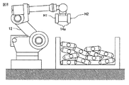
以下、図1〜図15を参照して本発明の実施形態に係る物品取出装置について説明する。図1は、本発明の一実施形態に係る物品取出装置10の概略構成を示す図である。物品取出装置10は、三次元測定機11と、ロボット12と、三次元測定機11とロボット12とに接続してロボット12を制御するロボット制御装置13とを有する。ロボット12は、アーム12aの先端部に取り付けられたハンド14を有する。ロボット12の側方にはコンテナ16が配置されている。なお、図1には、XYZの直交3軸座標系を併せて示している。Z方向は鉛直方向、X方向及びY方向は水平方向であり、コンテナ16はXZ平面上に示されている。
Hereinafter, an article take-out apparatus according to an embodiment of the present invention will be described with reference to FIGS. FIG. 1 is a diagram showing a schematic configuration of an article take-out
上方が開放されたコンテナ16内には、複数の物品20がバラ積みされている。本実施形態の物品取出装置10は、この複数の物品20がバラ積みされた状態から取出すべき物品20の位置及び姿勢を認識し、認識された物品20をコンテナ16の中からハンド14で取出して保持し、ロボット12の動作によりコンテナ16外の所定位置へ搬送する。複数の物品20は、図1では互いに同一形状として示しているが、不定形のものでもよく、複数の品種を含むものでもよい。なお、以下では、ハンド14で保持された物品20を、コンテナ16内の他の物品と区別するために保持物品21(図11参照)と呼ぶことがある。
A plurality of
ハンド14は、不図示の昇降機構により昇降可能な一対の保持部14aを有する。保持部14aは、通常は図1に示すように上昇状態にある。この上昇状態から下降して物品20を保持した後に、再度上昇する。これにより、保持物品21が他の物品20よりも上方(保持部14aの上昇する方向)に取出され、ロボット12の動作により保持物品21を搬送する際、保持物品21やハンド14とコンテナ16内の他の物品20との衝突を避けることができる。
The
三次元測定機11は、コンテナ16の中央部上方に配置され、コンテナ16内にバラ積みされた物品20のうち、露出した物品20の表面を測定して、複数の三次元点の位置情報(三次元情報)を取得する。三次元測定機11の測定範囲は、コンテナ16を含む必要があるが、測定範囲が大き過ぎると測定分解能の低下を招く。したがって、測定範囲は、コンテナ16の占有範囲と同等、例えばコンテナ16の占有範囲に一致させることが好ましい。なお、図1では、三次元測定機11が専用の架台15に固定されているが、ロボット12の先端部に三次元測定機11を取り付けてもよい。三次元測定機11とロボット制御装置13とは通信ケーブル等の通信手段によって互いに接続されており、互いに通信できるようになっている。
The three-
三次元測定機11としては、種々の非接触方式のものを利用することができる。例えば、カメラ2台のステレオ方式、レーザスリット光を走査する方式、レーザスポット光を走査する方式、プロジェクタ等の装置を用いてパターン光を物品に投影する方式、光が投光器から出射されてから物品表面で反射し受光器に入射するまでの飛行時間を利用する方式などが挙げられる。
As the three-
三次元測定機11は、取得した三次元情報を距離画像または三次元マップといった形式で表現する。距離画像とは、画像形式で三次元情報を表現したものであり、画像の各画素の明るさや色により、その画像上の位置の高さまたは三次元測定機11からの距離を表す。一方、三次元マップとは、測定された三次元座標値(x,y,z)の集合として三次元情報を表現したものである。本実施形態では、距離画像における各画素や三次元マップにおける三次元座標値を有する点を、三次元点と称し、複数の三次元点からなる集合を、三次元点集合と称する。三次元点集合は、三次元測定機11で測定した三次元点全体の集合であり、三次元測定機11により取得できる。
The three-
ハンド14は、物品20を取出し、かつ、保持することができるが、それが可能なハンドの形態としては、例えば吸引ノズル、吸着用磁石、吸着パッドまたはチャックなどが挙げられる。ハンド14は、ロボット12の動作により、その位置姿勢が制御される。
The
図2は、ロボット制御装置13で実行される処理、特に物品取出しに係る処理の一例を示すフローチャートである。以下、物品取出装置10による動作を、図2のフローチャート及び関連する図面を参照しつつ説明する。
FIG. 2 is a flowchart showing an example of processing executed by the
図2の処理は、例えば図示しない操作スイッチの操作により、物品20の取出開始指令が入力されると開始される。まず、三次元空間にバラ積みされた複数の物品20の表面を三次元測定機11で測定して三次元点集合30を取得する(ステップS1)。図3は、三次元測定機11で取得した三次元点集合30と、三次元点集合30を構成する三次元点31の一例を示す図である。図では、三次元点31が黒丸で示されており、三次元点集合30は、黒丸全体を含む点線で囲まれた領域として示されている。
The process of FIG. 2 is started when an instruction to start taking out the
次に、三次元点集合30から1以上の連結集合32を求める(ステップS2)。図4は、三次元点集合30から求めた連結集合32の一例を示す図である。図では、連結集合32は点線で囲まれた領域として示されている。すなわち、図4には、4つの連結集合32が示されている。
Next, one or more
ここで言う連結集合32とは、三次元点集合30の部分集合であり、任意の三次元点(第1の三次元点)31の近傍にその三次元点31とは異なる他の三次元点(第2の三次元点)31が存在する場合、第1の三次元点31と第2の三次元点31とが連結されてなるものである。例えば、図15に示すように複数の三次元点31(311〜317で表す)が測定され、311と312、312と313、313と314、及び315と316がそれぞれ所定距離内に存在する場合、これらは互いに連結される。この場合、312と313を介して311と314も連結されるため、311〜314は同一の連結集合321を構成する。一方、315と316は、311〜314のいずれにも連結されないため、別の連結集合322を構成する。317は、311〜316のいずれにも連結されないため、317のみで連結集合323を構成する。すなわち、連結集合32とは、互いに近傍に存在する三次元点を連結してなる三次元点の集合である。
The connected set 32 mentioned here is a subset of the three-dimensional point set 30, and another three-dimensional point different from the three-
三次元的測定機11によりバラ積みされた物品20の平面が測定される場合、同一物品20上における隣り合う三次元点31(例えば図4の31a,31b)は互いに近距離に位置する。これに対し、物品20の境界部では隣り合う三次元点(例えば図4の31b,31c)の位置が大きく変化する。したがって、三次元点31a,31bは同一の連結集合32に属するのに対し、三次元点31b,31cは互いに異なる連結集合32に属することになり、連結集合32により物品20を特定することができる。なお、連結集合32を求める具体的処理については、後述する(図14)。
When the planes of the
次に、同一の連結集合32に属する三次元点31の位置に基づき、各々の連結集合32を代表する代表位置姿勢33を求める(ステップS3)。連結集合32は物品20の露出する表面を特定するものであるので、代表位置姿勢33は、物品20を代表する位置及び姿勢となる。すなわち、ステップS3は、連結集合32を用いて物品20の位置及び姿勢を特定する処理であり、これにより物品20の位置及び姿勢を認識することができる。なお、物品20の位置及び姿勢は、三次元測定機11によって取得した三次元点31の位置情報に基づいて特定される。すなわち、物品20の露出部を計測して得られる三次元点31に基づき、計算により求められる。このため、物品20の配置が同じでも、露出状況が異なると、特定される物品20の位置及び姿勢は異なる。つまり、物品20の位置及び姿勢は、物品20の配置に対応して一義的に特定されるのではなく、物品20の表面の露出状況に応じて特定される。
Next, based on the positions of the three-
図5は、連結集合32に属する三次元点31の位置に基づいて計算した代表位置姿勢33の一例を表す示す図である。代表位置姿勢33は、直角に交差する一対の矢印33a,33bで示されているが、これは代表位置姿勢33が直交座標系で表されるためである。図5では、代表位置姿勢33が2つの矢印33a,33bで示されているが、代表位置姿勢33は二次元空間におけるものではなく、三次元空間におけるものである。
FIG. 5 is a diagram illustrating an example of the representative position and
代表位置姿勢33の求め方には、幾通りかの方法がある。まず、1つ目の例として、連結集合32に属する三次元点31の重心位置と所定の姿勢(例えば矢印33aを鉛直方向上方に向けた姿勢)とを組合せて代表位置姿勢33とする方法がある。重心位置の計算には、連結集合32に属する全ての三次元点31を利用しても良いし、別途、外れ値対策等の処理を導入して、選別した三次元点31を利用しても良い。外れ値対策としては、例えば、始めに連結集合32に属する全ての三次元点31を重心計算に利用して重心位置を求め、重心計算に利用した三次元点31で重心位置との距離が所定距離以上である三次元点31が存在する場合、重心計算に利用した三次元点31から重心位置との距離が大きい順に所定割合の三次元点31を除去する。そして残った三次元点31を重心計算に利用して重心位置を再計算する。この処理を、重心計算に利用した全ての三次元点31が重心位置から所定距離内に収まるまで繰り返せば良い。
There are several methods for obtaining the representative position and
2つ目の例として、連結集合32に属する三次元点31の位置に基づいて平面を求め、その平面上の1つの点(例えば重心となる点)の位置とその平面の法線方向に基づく姿勢とを組合せて代表位置姿勢33とする方法がある。平面は、連結集合32に属する全ての三次元点31を用いて最小二乗法で求めてもよいし、別途、何らかの外れ値対策の処理を導入して求めてもよい。外れ値対策の方法としては、M推定法、RANSAC、LMedS、ハフ変換など、幾通りかの方法がある。ハフ変換などの処理を入れることで、連結集合32が、複数の物品20の表面に跨っている場合でも、その中から、一つの平面を抽出して認識することが可能になる。
As a second example, a plane is obtained based on the position of the three-
連結集合32が、複数の物品20の表面に跨る場合とは、物品20の境界部における三次元点31(例えば図4の31b,31c)が互いに近距離に位置する場合であり、この場合には三次元点31b,31cが同一の連結集合32に属する。なお、ハフ変換を行って連結集合32内の複数の三次元点31が同一平面上にあるか否かを判定し、互いに異なる平面上にあると判定されると、連結集合32を各平面に対応した連結集合(例えば三次元点31bを含む連結集合32と三次元点31cを含む連結集合32)に分割するようにしてもよい。これにより連結集合32が修正され、物品20毎に精度よく連結集合32を求めることができる。
The case where the connected set 32 straddles the surface of the plurality of
3つ目の例として、連結集合32に属する三次元点31の位置に基づいて曲面を求め、その曲面上の1つの点(例えば重心に最も近い曲面上の点)の位置とその位置における曲面の法線方向とに基づく姿勢とを組合せて代表位置姿勢33とする方法がある。曲面は、連結集合32に属する全ての三次元点31を用いて最小二乗法で求めてもよいし、別途、何らかの外れ値対策の処理を導入して求めてもよい。外れ値対策の方法としては、M推定法、RANSAC、LMedS、ハフ変換など、幾通りかの方法がある。ハフ変換などの処理を用いることで、連結集合32が、複数の物品の表面に跨っている場合でも、その中から、一つの曲面を抽出して認識することが可能になる。
As a third example, a curved surface is obtained based on the position of the three-
4つ目の例として、連結集合32に属する各三次元点31の位置に基づいて穴を求め、その穴の位置及び姿勢(穴が穿設される方向)を代表位置姿勢33とする方法がある。この方法は、物品20に穴が設けられている場合に有効である。一例を示せば、まず、連結集合32内に、所定面積以上の三次元点31が存在しない閉じた領域(三次元点不存在領域)があるか否かを判定し、三次元点不存在領域があると判定されると、その三次元点不存在領域が穴であると仮定する。次に、穴の縁にある三次元点31の重心位置を求め、これを穴の位置とする。さらに、穴の縁にある三次元点31の位置に基づいて平面を求め、その平面の法線方向に基づく姿勢を、穴の姿勢とする。
As a fourth example, there is a method in which a hole is obtained based on the position of each three-
図5は、上記4つの例のうち、2つ目の例によって代表位置姿勢33を求めた場合を示している。ステップS3では、連結集合32に属する三次元点31が存在する領域の面積を演算し、面積が所定値より小さい連結集合32(図4の32a)からは、代表位置姿勢33を取得しない。すなわち、表面が十分に露出していると判断される連結集合32に対してのみ、代表位置姿勢33を求める。代表位置姿勢33を求めていない連結集合32aは、物品取出しの対象としない。これにより、連結集合32aによって表される物品20、すなわち上面の一部が他の物品20で覆われている奥側の物品20にハンド14が接近することを防止でき、ハンド14と取出し対象以外の物品20とが衝突することを抑制できる。
FIG. 5 shows a case where the representative position /
次に、各々の代表位置姿勢33に対応するハンド位置姿勢34を求める(ステップS4)。図6は、代表位置姿勢33に対応するハンド位置姿勢34の一例を表す示す図である。ハンド位置姿勢34は、代表位置姿勢33と同様に、直角に交差する一対の矢印34a,34bで示されている。
Next, a hand position /
ハンド位置姿勢34の位置(矢印34a,34bの交点)及び姿勢(矢印34a,34bの方向)の求め方には、それぞれ幾通りずつかの方法がある。位置に関しては、例えば、代表位置姿勢33の位置をそのままハンド位置姿勢34の位置とする方法がある。別の例として、代表位置姿勢33の位置よりも所定の座標軸35(例えばZ軸)の向きに沿って所定長移動した位置を、ハンド位置姿勢34の位置とする方法もある。図6は、後者の例で位置を示している。姿勢に関しては、例えば、代表位置姿勢33の姿勢をそのままハンド位置姿勢34の姿勢とする方法がある。別の例として、代表位置姿勢33の位置がコンテナ16の壁に近い場合、壁とハンドとの衝突を避ける目的で壁から離れる方向にハンドを傾けるようにする方法もある。図6は、前者の例で姿勢を示している。
There are several methods for obtaining the position (intersection of
次に、各々のハンド位置姿勢34にP1,P2,・・・,Pnとナンバリングする(ステップS5)。但し、nはハンド位置姿勢34の個数である。図7は、ナンバリングされたハンド位置姿勢34を示す図であり、所定の座標軸35に対する座標値の降順、つまり、高い位置にあるものから順番にナンバリングされている。なお、図7では、n=3である。
Next, P1, P2,..., Pn are numbered in each hand position / posture 34 (step S5). Here, n is the number of hand position /
次に、ハンド14の保持部14aにH1,H2,・・・,Hmとナンバリングする(ステップS6)。但し、mは保持部14aの個数である。図8は、ナンバリングされた保持部14aを示しており、図8では、m=2である。
Next, H1, H2,..., Hm are numbered in the holding
次に、自然数値を取る変数j,kに対して初期値を与える。すなわち、j←1,k←1とする(ステップS7)。変数jは保持部14aの番号の指定に用い、変数kはハンド位置姿勢34の番号の指定に用いる。
Next, initial values are given to variables j and k that take natural values. That is, j ← 1 and k ← 1 are set (step S7). The variable j is used to specify the number of the holding
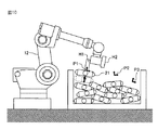
次に、図9に示すように、保持部14a駆動用のアクチュエータ(電動モータあるいはシリンダ)に制御信号を出力し、保持部Hjを下降させるとともに、ロボット駆動用のアクチュエータ(電動モータ)に制御信号を出力し、ロボット12の動作により保持部Hjをハンド位置姿勢Pkへ移動させる(ステップS8)。変数の初期値j=1,k=1に対しては、Hj=H1,Pk=P1である。
Next, as shown in FIG. 9, a control signal is output to the actuator (electric motor or cylinder) for driving the holding
次に、保持部Hj駆動用のアクチュエータに物品20を保持するための制御信号を出力し、図10に示すように保持部Hjの下端面で保持物品21を保持する(ステップS9)。例えば、保持部Hjが吸引ノズルを有する場合、真空ポンプを作動し、吸引力で保持物品21を吸引、保持する。保持部Hjが吸着用磁石を有する場合、電磁コイルに電流を流して磁石を作動し、磁力で保持物品21を吸着、保持する。保持部Hjがチャックである場合、チャックを開くあるいは閉じることで、保持物品21を保持する。
Next, a control signal for holding the
次に、図11に示すように、保持部Hj駆動用のアクチュエータに制御信号を出力し、保持物品21を保持した保持部Hjを上昇させる(ステップS10)。保持部Hjを上昇させることで、ロボット12の動作によりハンド14を移動させる際、保持物品21や保持部Hjと他の物品20との衝突を避けることができる。
Next, as shown in FIG. 11, a control signal is output to the actuator for driving the holding portion Hj, and the holding portion Hj holding the holding
次に、保持部14aによる保持物品21の保持が成功したか否かを判定する(ステップS11)。この判定は、例えば、保持部14aが吸引ノズルを有する場合、吸引時のエアの流量や圧力の変化に応じて保持が成功したか否かを判定すればよい。保持部Hjが吸着用磁石を有する場合、近接センサで保持物品21が存在するか否かを判定し、その存否に応じて保持が成功したか否かを判定すればよい。保持部Hjがチャックを有する場合、開閉確認センサでチャックの開閉状態を確認し、保持が成功したか否かを判定すればよい。保持が成功したと判定されると、ステップS12へ進む。保持が成功していないと判定されると、ステップS14へ進む。
Next, it is determined whether or not the holding
ステップS12では、j<mか否かを判定する。この判定は、m個(図11では2個)の保持部14aの中に保持物品21を未だ保持していないものが存在するか否かの判定である。j<mと判定されると、保持部Hj+1が保持物品21を未だ保持していないので、j←j+1とし(ステップS13)、ステップS14へ進む。j<mでないと判定されると、全ての保持部14aが保持物品21を保持しているので、ステップS16へ進む。
In step S12, it is determined whether j <m. This determination is a determination as to whether or not there are m (two in FIG. 11) holding
ステップS14では、k<nか否かを判定する。この判定は、n個(図11では3個)のハンド位置姿勢34の中に保持部14aが未だ到達していないものが存在するか否かの判定である。k<nと判定されると、ハンド位置姿勢Pk+1に保持部14aが未だ到達していないので、k←k+1とし(ステップS15)、ステップS8へ戻る。そして、図12に示すように次の保持部Hjを下降させながらロボット12の動作により次のハンド位置姿勢Pkへ移動させる。なお、図12は、Hj=H2,Pk=P2の例である。次いで、この保持部Hjに物品吸着用の制御信号を出力し、図13に示すように、次の保持物品21を保持する(ステップS9)。ステップS14でk<nでないと判定されると、n個のハンド位置姿勢34の全てに保持部14aが到達したので、ステップS16へ進む。
In step S14, it is determined whether k <n. This determination is a determination as to whether there are n (three in FIG. 11) hand position / postures 34 to which the
ステップS16では、ロボット駆動用アクチュエータに制御信号を出力し、ハンド14を所定位置に移動する。これにより保持物品21がロボット12の動作により所定位置に搬送される。その後、保持部駆動用アクチュエータに制御信号を出力し、保持物品21を保持部14aから取外す。以上で、1サイクルの処理が終了となる。なお、未到達のハンド位置姿勢34があるにも拘わらず(k<n)、全ての保持部14aで保持物品21を保持している場合(j≧m)、ステップS16で保持物品21を所定位置に搬送して保持部14aから取外した後に、保持部14aの番号jを初期値1にして、ステップS8以降の処理が繰り返される。
In step S16, a control signal is output to the robot driving actuator, and the
ここで、連結集合32(ステップS2)を求めるための具体的処理について説明する。図14は、連結集合32を求めるための処理(連結集合演算処理)の一例を示すフローチャートである。 Here, a specific process for obtaining the connected set 32 (step S2) will be described. FIG. 14 is a flowchart illustrating an example of processing for obtaining the linked set 32 (linked set calculation processing).
まず、ステップS21で、三次元点集合30に属する全ての三次元点31に、初期のラベル番号として、どの連結集合32にも属していないことを表すラベル番号0を割り振る。以下では、自然数であるラベル番号jが割り振られた三次元点31を、31(j)で表す。ラベル番号jは、連結集合32に対応して割り振られる番号であり、0ではない同一のラベル番号jが割り振られていれば、同一の連結集合32に属することになる。次に、ステップS22で、1番目の連結集合32を求めるため、ラベル番号jを1とする(j←1)。
First, in step S21, all three-
次に、ステップS23で、三次元点集合30に属する三次元点31であって、ラベル番号が0である任意の三次元点31(0)を選択する。ステップS24では、ラベル番号が0である三次元点31(0)が選択されたか否かを判定し、肯定されるとステップS25に進む。三次元点31(0)が選択されなかった場合は、三次元点集合30に属する全ての三次元点31が何れかの連結集合32に属している。この場合は、ステップS24が否定され、連結集合演算処理が終了し、図2のステップS3に進む。
Next, in step S23, an arbitrary three-dimensional point 31 (0) that is a three-
ステップS25では、ラベル番号がjである三次元点31(j)を格納するためのリストLjを準備する。ステップS26では、ステップS24で選択された三次元点31(0)にラベル番号jを割り振った後に、その三次元点31(j)をリストLjに追加する。ステップS27では、自然数値を取る変数kに対して、初期値1を与える(k←1)。kは、リストLjに含まれる三次元点31(j)を指定する番号である。なお、リストLjには、追加された三次元点31(j)が追加された順番に並んでいるものとする。
In step S25, a list Lj for storing the three-dimensional point 31 (j) with the label number j is prepared. In step S26, after assigning the label number j to the three-dimensional point 31 (0) selected in step S24, the three-dimensional point 31 (j) is added to the list Lj. In step S27, an
ステップS28では、リストLjのk番目の三次元点31(j)の近傍に、ラベル番号が0である三次元点31(0)が存在するか否かを判定する。ステップS28が肯定されるとステップS29に進み、否定されるとステップS29をパスしてステップS30に進む。ステップS29では、リストLjのk番目の三次元点31(j)の近傍に存在すると判定された全ての三次元点31(0)にラベル番号jを割り振った後、これら三次元点31(j)をリストLjの最後に追加する。ステップS30では、変数kに1を追加する(k←k+1)。 In step S28, it is determined whether or not a 3D point 31 (0) having a label number of 0 exists in the vicinity of the k-th 3D point 31 (j) in the list Lj. If step S28 is affirmed, the process proceeds to step S29, and if not, step S29 is passed and the process proceeds to step S30. In step S29, after assigning label numbers j to all the three-dimensional points 31 (0) determined to exist in the vicinity of the k-th three-dimensional point 31 (j) in the list Lj, these three-dimensional points 31 (j ) Is added to the end of the list Lj. In step S30, 1 is added to the variable k (k ← k + 1).
ステップS31では、kの値がリストLjに格納されている三次元点31(j)の数(要素数N)より大きいか否かを判定する。kが要素数Nより大きい場合、リストLjに格納されたN個の全ての三次元点31(j)に対する近傍判定の処理が終了しており、リストLj内の三次元点31(j)の近傍にある三次元点が既に同一のリストLj内に格納されている。このため、リストLjに三次元点31(j)を追加する処理を終了し、ステップS32に進む。それ以外の場合は、リストLj内の全ての三次元点31(j)に対し近傍判定の処理が終了していないため、ステップS28に戻り、リストLjへ三次元点31(j)を追加する処理を繰り返す。 In step S31, it is determined whether or not the value of k is larger than the number of three-dimensional points 31 (j) stored in the list Lj (number of elements N). When k is larger than the number of elements N, the neighborhood determination processing for all N three-dimensional points 31 (j) stored in the list Lj is completed, and the three-dimensional points 31 (j) in the list Lj The neighboring three-dimensional points are already stored in the same list Lj. For this reason, the process of adding the three-dimensional point 31 (j) to the list Lj is terminated, and the process proceeds to step S32. In other cases, the proximity determination process has not been completed for all the three-dimensional points 31 (j) in the list Lj, so the process returns to step S28 and the three-dimensional point 31 (j) is added to the list Lj. Repeat the process.
ステップS32では、ラベル番号jに1を追加し(j←j+1)、ステップS23に戻る。以降、ステップS23〜ステップS32と同様の処理を繰り返し、次のラベル番号jに対応する連結集合32を求める。
In step S32, 1 is added to the label number j (j ← j + 1), and the process returns to step S23. Thereafter, the same processing as in steps S23 to S32 is repeated to obtain a
以上の連結集合演算処理を、図15を参照して具体的に説明する。連結集合演算処理の開始時には、全ての三次元点311〜317が連結集合32に属しておらず、三次元点311〜317のラベル番号は0である(ステップS21)。この状態から、ラベル番号1の連結集合32を作成するため、例えば三次元点313を選択すると(ステップS23)、その三次元点313にラベル番号1を割り振った後(313(1))、三次元点313をラベル番号1のリストL1の1番目に格納する(ステップS26)。
The above-described connected set calculation processing will be specifically described with reference to FIG. At the start of the connected set calculation process, all the three-
次いで、リストL1の1番目の三次元点313の近傍に、ラベル番号0の三次元点31(0)が存在するか否かを判定する(ステップS28)。この場合、ラベル番号0の三次元点312,314が存在するため、これら三次元点312,314にラベル番号1をそれぞれ割り振り(312(1),314(1))、リストL1の2番目及び3番目にそれぞれ追加する(ステップS29)。これによりリストL1の要素数Nは3となる。
Next, it is determined whether or not the 3D point 31 (0) with the label number 0 exists in the vicinity of the
その後、kが2(<N)となり(ステップS30)、リストL1の2番目の三次元点312の近傍に、ラベル番号0の三次元点31(0)が存在するか否かを判定する(ステップS28)。この場合、ラベル番号0の三次元点311が存在するため、この三次元点311にラベル番号1を割り振り(311(1))、リストL1の4番目に追加する(ステップS29)。これによりリストL1の要素数Nは4となる。
Thereafter, k becomes 2 (<N) (step S30), and it is determined whether or not the 3D point 31 (0) with the label number 0 exists in the vicinity of the
その後、kが3(<N)となり(ステップS30)、リストL1の3番目の三次元点314の近傍に、ラベル番号0の三次元点31が存在するか否かを判定する(ステップS28)。この場合、三次元点314の近傍にラベル番号0の三次元点31は存在しないため、要素数Nが4のままkが4となり(ステップS30)、リストL1の4番目の三次元点311の近傍に、ラベル番号0の三次元点31(0)が存在するか否かを判定する(ステップS28)。この場合、三次元点311の近傍にラベル番号0の三次元点31は存在しないため、要素数Nが4のままkが5となる(ステップS30)。
Thereafter, k becomes 3 (<N) (step S30), and it is determined whether or not the
このとき、kは要素数Nよりも大きくなるため、ラベル番号1のリストL1の作成を終了し、ラベル番号を2として(ステップS32)、同様の処理を繰り返す。繰り返しの処理では、例えばラベル番号0の三次元点315,316にラベル番号2を割り振って、三次元点315(2),316(2)をリストL2に追加し、ラベル番号0の三次元点317にラベル番号3を割り振って、三次元点317(3)をリストL3に追加する。これにより、ラベル番号0の三次元点31が不存在となるため、ステップS24が否定され、連結集合演算処理を終了する。
At this time, since k is larger than the number N of elements, the creation of the list L1 with the
以上の処理では、連結集合32を求める際に、近傍判定部としての機能を有するロボット制御装置13内での処理により、三次元点31の近傍に他の三次元点31が存在するか否かを判定するようにした(ステップS28)。近傍判定部では、例えば、予めXYZの三次元の座標系に対応して所定距離aを定め、三次元点集合30に属する第1三次元点31(例えば図15の311)と第2三次元点31(例えば図15の312)との間の距離Dが所定距離a以内である場合に、第1三次元点311の近傍に第2三次元点312が存在すると判定すればよい。XYZの三次元の座標系ではなく、XYの二次元の座標系とZの一次元の座標系に対応してそれぞれ所定距離xya,zaを定め、XYの二次元の座標系とZの一次元の座標系に関する三次元点311,312間の距離Dxy,Dzを求め、この距離Dxy,Dzがそれぞれ予め定めた所定値xya,za以内のときに、三次元点311の近傍に三次元点312が存在すると判定してもよい。
In the above processing, whether or not another three-
三次元点集合30が距離画像の形で表され、距離画像の各画素が縦横等間隔に並んでいるとき、近傍判定部は、例えば以下のようにして三次元点同士の近傍判定を行うようにしてもよい。すなわち、距離画像の各画素の明るさの尺度となる1次元座標系を定義し、1次元座標系に対し、所定距離に対応して明るさの差を表す閾値を定義する。第1三次元点と第2三次元点が距離画像上で隣接する画素であり、かつ、対応する画素間の明るさの差が閾値以内のときに、第1三次元の近傍に第2三次元点があると判定すればよい。 When the three-dimensional point set 30 is represented in the form of a distance image and the pixels of the distance image are arranged at equal intervals in the vertical and horizontal directions, the proximity determination unit performs, for example, the determination of the proximity of the three-dimensional points as follows. It may be. That is, a one-dimensional coordinate system that is a measure of the brightness of each pixel of the distance image is defined, and a threshold value that represents a difference in brightness corresponding to a predetermined distance is defined for the one-dimensional coordinate system. When the first 3D point and the second 3D point are adjacent pixels on the distance image and the brightness difference between the corresponding pixels is within a threshold value, the second 3D point is placed near the first 3D point. What is necessary is just to determine with an origin point.
本実施形態によれば、以下のような作用効果を奏することができる。
(1)三次元空間にバラ積みされた物品20の表面位置を三次元測定機11で測定して複数の三次元点31の位置情報を取得するようにした。さらに、ロボット制御装置13での処理により、三次元点集合30から互いに近傍にある三次元点31を連結してなる連結集合32を求め(ステップS2)、連結集合32に属する三次元点31の位置情報に基づき、物品20を取出可能なハンド14(保持部14a)の位置姿勢(ハンド位置姿勢34)を求め(ステップS3〜ステップS4)、求められたハンド位置姿勢34にハンド14を移動してコンテナ内から物品21を取出すようにロボット12を制御した(ステップS8〜ステップS10)。
According to this embodiment, the following operational effects can be achieved.
(1) The surface position of the
このようにして求められた連結集合32は、三次元測定機11に向けて露出している物品表面の位置及び姿勢(傾き)を反映するものであり、パターンマッチング等によらず物品20の位置及び姿勢を特定することができる。このため、物品20のモデルパターンを作成する必要がなく、多品種や不定形の物品20であっても容易にその位置及び姿勢を認識して、物品20を保持することができる。また、追加された新品種の物品20に対してもモデルパターンを追加無しでその位置及び姿勢を認識することができ、物品20の位置姿勢の認識失敗や誤認識、或いは物品20の取損ねや衝突等の問題を回避し、上方にある取出し易い物品20へハンド14を高速に移動させて物品20を効率良く取出すことができる。
The connection set 32 obtained in this way reflects the position and posture (tilt) of the article surface exposed toward the coordinate measuring
これに対し、例えば、物品の二次元モデルパターンを用いて二次元パターンマッチングにより物品の位置を認識する方法では、二次元モデルパターンを作成する必要があり、手間を要する。とくに、物品が多品種の場合には、品種数分のモデルパターンを作成する必要があり、多大な手間が必要となる。さらに、この方法には、本実施形態と比較した場合に以下のような問題点がある。バラ積みされた物品20は様々な姿勢となり、各姿勢に対応した二次元パターンマッチングを行う場合、例えば二次元の幾何学的変換を施して得られる変換二次元モデルパターンを利用する必要があるが、この方法で対応できるのは、平面的な物品に限られる。通常の立体的な物品に二次元パターンマッチングを適用しようとすると、幾何学的変換では補い切れない見え方の多様性を考慮して、物品一品種についてだけでも表・裏・横・斜めと幾つかの方向から二次元モデルパターンを作成する必要が生じる。さらに、多品種への対応を考慮すると、品種数を乗じた膨大な数の二次元モデルパターンを作成する必要が生じ、多大な手間を要する。また、不定形の物品の場合には、二次元モデルパターンを作成できないので、その位置を認識することはできない。バラ積みされた物品20は、照明の当たり具合が悪かったり他の物品20の影が写ったり物品20が想定以上に傾いたりするため、撮像条件が悪い。したがって、物品20の位置姿勢の認識失敗や誤認識が発生したり、上方に位置する取出すべき物品の位置の認識に失敗したり、下方に位置する物品の位置が先に認識されたりするおそれがある。誤認識された物品位置姿勢や下方にある物品位置を目掛けてロボット12のハンド14の位置姿勢を制御すると、物品20を取損ねて装置の作業効率が落ちるばかりか、ハンド14と物品20とが衝突してそれらを損傷させるおそれがある。損傷を回避しようとすると、ロボット12の移動速度を遅くせざるを得ず、作業効率が悪化する。
On the other hand, for example, in a method of recognizing the position of an article by two-dimensional pattern matching using a two-dimensional model pattern of the article, it is necessary to create a two-dimensional model pattern, which is troublesome. In particular, when there are many types of articles, it is necessary to create model patterns for the number of types, which requires a lot of labor. Furthermore, this method has the following problems when compared with the present embodiment. When the two-dimensional pattern matching corresponding to each posture is performed, for example, it is necessary to use a transformed two-dimensional model pattern obtained by performing a two-dimensional geometric transformation. This method can only deal with planar articles. When trying to apply two-dimensional pattern matching to normal three-dimensional articles, considering the variety of appearance that cannot be compensated for by geometric transformation, there are several types of articles, front, back, side, and diagonal. It is necessary to create a two-dimensional model pattern from any direction. Furthermore, considering the correspondence to various types, it becomes necessary to create a huge number of two-dimensional model patterns multiplied by the number of types, which requires a lot of labor. In addition, in the case of an irregularly shaped article, since the two-dimensional model pattern cannot be created, its position cannot be recognized. Since the
また、例えば、物品の三次元モデルパターンを用いて三次元パターンマッチングにより物品の位置を認識する方法においても、三次元モデルパターンを作成する必要があり、手間を要する。とくに、物品が多品種の場合には、品種数分のモデルパターンを作成する必要があり、多大な手間が必要となる。さらに、この方法には、本実施形態と比較した場合に以下のような問題点がある。不定形の物品は、三次元モデルパターンを作成できないので、その位置を認識することはできない。バラ積みされた物品20は、三次元測定機11に向いていない側の三次元点31を取得でない上に、大きく傾いたり近隣の物品に邪魔されたりするため、撮像条件が悪い。このため、三次元パターンマッチングにより物品の三次元姿勢を決定できるほど量・質ともに十分な三次元点集合を得るのは困難であり、物品の位置姿勢の認識失敗や誤認識が発生したり、上方に位置する取出すべき物品の位置の認識に失敗し、下方に位置する物品の位置が先に認識されたりするおそれがある。誤認識された物品位置姿勢や下方にある物品位置を目掛けてロボット12のハンド14の位置姿勢を制御すると、物品20を取損ねて装置の作業効率が落ちるばかりか、ハンド14と物品20とが衝突してそれらを損傷させるおそれがある。損傷を回避しようとすると、ロボット12の移動速度を遅くせざるを得ず、作業効率が悪化する。
Further, for example, also in a method of recognizing the position of an article by three-dimensional pattern matching using the three-dimensional model pattern of the article, it is necessary to create a three-dimensional model pattern, which is troublesome. In particular, when there are many types of articles, it is necessary to create model patterns for the number of types, which requires a lot of labor. Furthermore, this method has the following problems when compared with the present embodiment. Since the three-dimensional model pattern cannot be created for an irregularly shaped article, its position cannot be recognized. The
(2)ロボット制御装置13での処理により、三次元点集合30に属する任意の三次元点31(第1三次元点)とこれとは別の三次元点31(第2三次元点)との間の所定の座標系(例えばXYZ座標系)に関する距離Dが、予め定められた所定距離a以内にあるか否かを判定し、所定距離a以内にあると判定されると、第1三次元点31と第2三次元点31に同一のラベル番号jを割り振ってこれらを連結するようにした(ステップS28、ステップS29)。したがって、各物品20の表面の位置姿勢を表す連結集合32を、容易かつ精度よく作成することができる。また、三次元点集合30から抽出されたエッジによって囲まれた部分領域に三次元点集合30を分割する手法に比べ、三次元点集合30のデータに欠損がある場合においても、安定して物品20を保持可能な面の位置及び姿勢を認識することができる。
(2) An arbitrary three-dimensional point 31 (first three-dimensional point) belonging to the three-dimensional point set 30 and a different three-dimensional point 31 (second three-dimensional point) by the processing in the
(3)ロボット制御装置13での処理により、連結集合32に属する三次元点31の位置に基づき、連結集合32を代表する位置及び姿勢である代表位置姿勢33を求め、この代表位置姿勢33に対応してハンド位置姿勢34を求めるようにした(ステップS3、ステップS4)。これにより、物品20とハンド14との位置関係を、ハンド14の種類等に応じて適切に設定することができる。
(3) Based on the position of the three-
(4)ロボット制御装置13での処理(ステップS3)により、連結集合32に属する三次元点31の重心位置とこの重心位置における所定の姿勢とを組合せて代表位置姿勢を求めるようにすると、保持物品21をハンド14で安定して保持することができる。連結集合32に属する三次元点31の位置に基づいて平面または曲面を求め、求めた平面または曲面上の1つの点の位置と平面または曲面の法線方向に基づく姿勢とを組合せて代表位置姿勢33を求めるようにすると、物品20の表面が傾いている場合に、その傾きに合わせて代表位置姿勢33を算出することができる。
(4) If the representative position / posture is obtained by combining the center of gravity of the three-
(5)表面に穴を有する物品20に対しては、連結集合32に属する三次元点31の位置に基づいて穴を求め、その穴の位置及び姿勢(穴の方向)を代表位置姿勢33とすることで、保持部14aがチャックであるハンド14を用い、内径把持にて物品20を保持することができる。
(5) For the
なお、バラ積みされた複数の物品20の表面位置を三次元測定機11で測定して複数の三次元点31の位置情報を取得し、複数の三次元点点31の中から、互いに近傍にある三次元点31を連結してなる連結集合32を求め、連結集合32に属する三次元点31の位置情報に基づき、取出し可能な物品20の位置及び姿勢を特定し、この位置姿勢に対応したハンド位置姿勢34を求め、ハンド位置姿勢34にハンド14を移動して物品20(保持物品21)を取出すようにロボット12を制御するのであれば、物品取出方法の構成はいかなるものでもよい。
It should be noted that the surface positions of the plurality of
上記実施形態では、ハンド14に2つの保持部14aを設けるようにしたが、保持部14aを3個以上設けてもよく、1つだけ設けるようにしてもよい。三次元点集合30に属する第1三次元点31(例えば図15の311)と第2三次元点31(例えば図15の312)との間の所定の座標系に関する距離が所定距離内にあるときに、第1三次元点311と第2三次元点312を連結して連結集合32を演算するようにしたが(ステップS2)、互いに近傍にある三次元点31,31を連結してなる連結集合32を求めるのでれば、連結集合演算手段としてのロボット制御装置13の構成は上述したものに限らない。
In the above embodiment, the two holding
連結集合32に属する三次元点31の位置情報に基づき、連結集合32を代表する代表位置姿勢33を演算するようにしたが(ステップS3)、連結集合32によって表される物品20の位置及び姿勢を特定するのであれば、物品特定手段としてのロボット制御装置13の構成は上述したものに限らない。ここで、連結集合32を代表する位置及び姿勢は、物品20を代表する位置及び姿勢でもあり、物品20の位置及び姿勢を特定するとは、物品を代表する位置及び姿勢を求めて物品20の配置を特定することを意味する。
The representative position and
上記実施形態では、代表位置姿勢33からハンド位置姿勢34を演算するようにしたが(ステップS4)、代表位置姿勢33として特定された物品20を取出し可能なハンド位置姿勢34を求めるのであれば、ハンド位置姿勢演算手段としてのロボット制御装置13の構成は上述したものに限らない。ハンド位置姿勢34へハンド14を移動して物品20を取出すようにロボット12を制御するのであれば、ロボット制御手段としてのロボット制御装置13の構成はいかなるものでもよい。
In the above embodiment, the hand position /
すなわち、上述した物品取出装置10の構成(図1)は一例であり、連結集合演算手段(ステップS2)、物品特定手段(ステップS3)、ハンド位置姿勢演算手段(ステップS4))、ロボット制御手段(ステップS8〜ステップS10)としてのロボット制御装置13の構成は上述したものに限らない。
That is, the configuration (FIG. 1) of the article take-out
以上の説明はあくまで一例であり、本発明の特徴を損なわない限り、上述した実施形態及び変形例により本発明が限定されるものではない。上記実施形態及び変形例の構成要素には、発明の同一性を維持しつつ置換可能かつ置換自明なものが含まれる。すなわち、本発明の技術的思想の範囲内で考えられる他の形態についても、本発明の範囲内に含まれる。また、上記実施形態と変形例の1つまたは複数を任意に組み合わせることも可能である。 The above description is merely an example, and the present invention is not limited to the above-described embodiments and modifications unless the features of the present invention are impaired. The constituent elements of the above-described embodiments and modifications include those that can be replaced while maintaining the identity of the invention and that are obvious for replacement. That is, other forms conceivable within the scope of the technical idea of the present invention are also included in the scope of the present invention. Moreover, it is also possible to arbitrarily combine one or more of the above-described embodiments and modified examples.
10 物品取出装置
11 三次元測定機
12 ロボット
13 ロボット制御装置
14 ハンド
14a 保持部
16 コンテナ
20 物品
21 保持物品
30 三次元点集合
31 三次元点
32 連結集合
33 代表位置姿勢
34 ハンド位置姿勢
35 座標軸
DESCRIPTION OF
Claims (8)
三次元空間にバラ積みされた複数の物品の表面位置を測定し、複数の三次元点の位置情報を取得する三次元測定機と、
前記三次元点測定機によって取得された複数の三次元点の中から、互いに近傍にある三次元点を連結してなる連結集合を求める連結集合演算手段と、
前記連結集合に属する三次元点の位置情報に基づき、前記連結集合を代表する位置及び姿勢である代表位置姿勢を求めて物品の位置及び姿勢を特定する物品特定手段と、
前記物品特定手段により位置及び姿勢が特定された物品を取出し可能な前記ハンドの位置及び姿勢であるハンド位置姿勢であって、前記代表位置姿勢に対応するハンド位置姿勢を求めるハンド位置姿勢演算手段と、
前記ハンド位置姿勢演算手段により求められたハンド位置姿勢へ前記ハンドを移動して前記物品を取出すように前記ロボットを制御するロボット制御手段と、
を備えることを特徴とする物品取出装置。 A robot having a hand capable of holding an article;
A three-dimensional measuring machine for measuring the surface positions of a plurality of articles stacked in a three-dimensional space and acquiring positional information of a plurality of three-dimensional points;
A connected set calculation means for obtaining a connected set obtained by connecting three-dimensional points in the vicinity from each other among a plurality of three-dimensional points acquired by the three-dimensional point measuring machine;
Based on position information of three-dimensional points belonging to the connected set, article specifying means for determining a representative position and posture, which is a position and posture representing the connected set, and specifying the position and posture of the article;
A hand position / posture calculating means for obtaining a hand position / posture corresponding to the representative position / posture , the hand position / posture being the position and posture of the hand from which the article whose position and posture is specified by the article specifying unit can be taken out; ,
Robot control means for controlling the robot to move the hand to the hand position and orientation determined by the hand position and orientation calculation means and take out the article;
An article take-out apparatus comprising:
前記三次元測定機によって取得された複数の三次元点は三次元点集合を構成し、
前記連結集合演算手段は、所定の座標系に関する、前記三次元点集合に属する第1三次元点と第2三次元点との間の距離が、予め定められた所定距離以内にあるか否かを判定する近傍判定部を有し、該近傍判定部により前記第1三次元点と前記第2三次元点との間の距離が前記所定距離以内にあると判定されると、前記第1三次元点と前記第2三次元点とを連結することを特徴とする物品取出装置。 The article take-out device according to claim 1,
A plurality of three-dimensional points acquired by the three-dimensional measuring machine constitutes a three-dimensional point set,
Whether the connection set operation means, for a given coordinate system, the distance between the first three-dimensional point and the second three-dimensional points belonging to the three-dimensional point set is located within a predetermined et a predetermined distance A proximity determining unit that determines whether the distance between the first 3D point and the second 3D point is within the predetermined distance. An article take-out apparatus that connects a three-dimensional point and the second three-dimensional point.
前記物品特定手段は、前記連結集合に属する三次元点の重心位置と該重心位置における所定の姿勢とを組合せて前記代表位置姿勢を求めることを特徴とする物品取出装置。 The article extraction device, wherein the article specifying unit obtains the representative position / posture by combining a barycentric position of a three-dimensional point belonging to the connected set and a predetermined posture at the barycentric position.
前記物品特定手段は、前記連結集合に属する三次元点の位置に基づいて平面を求め、該平面上の1つの点の位置と該平面の法線方向に基づく姿勢とを組合せて前記代表位置姿勢を求めることを特徴とする物品取出装置。 The article specifying unit obtains a plane based on a position of a three-dimensional point belonging to the connected set, and combines the position of one point on the plane and an attitude based on a normal direction of the plane to represent the representative position and attitude. An article take-out apparatus characterized by:
前記物品特定手段は、前記連結集合に属する三次元点の位置に基づいて曲面を求め、該曲面上の1つの点の位置と該位置における該曲面の法線方向に基づく姿勢とを組合せて前記代表位置姿勢を求めることを特徴とする物品取出装置。 The article specifying means obtains a curved surface based on the position of a three-dimensional point belonging to the connected set, and combines the position of one point on the curved surface and the posture based on the normal direction of the curved surface at the position. An article take-out apparatus for obtaining a representative position and orientation.
前記物品特定手段は、前記連結集合に属する三次元点の位置に基づいて、所定面積以上の三次元点が存在しない閉じた領域が穴であると仮定して穴を求めるとともに、該穴の位置及び姿勢を求め、これら穴の位置及び姿勢を組合せて前記代表位置姿勢を求めることを特徴とする物品取出装置。 The article specifying means obtains a hole based on the position of a three-dimensional point belonging to the connected set on the assumption that a closed region where a three-dimensional point having a predetermined area or more does not exist is a hole, and the position of the hole And the posture, and the representative position and posture are obtained by combining the positions and postures of the holes.
前記ハンドが、吸引ノズル又は電磁石又は吸着パッド又はチャックのいずれかを有することを特徴とする物品取出装置。 The article take-out apparatus, wherein the hand has any one of a suction nozzle, an electromagnet, a suction pad, and a chuck.
前記バラ積みされた複数の物品の表面位置を三次元測定機で測定して複数の三次元点の位置情報を取得し、 Measuring the surface position of the plurality of stacked articles with a three-dimensional measuring machine to obtain position information of a plurality of three-dimensional points;
前記三次元点測定機によって取得された複数の三次元点の中から、互いに近傍にある三次元点を連結してなる連結集合を求め、 From a plurality of three-dimensional points acquired by the three-dimensional point measuring machine, to obtain a connected set obtained by connecting three-dimensional points in the vicinity of each other,
前記連結集合に属する三次元点の位置情報に基づき、前記連結集合を代表する位置及び姿勢である代表位置姿勢を求めて物品の位置及び姿勢を特定し、 Based on the position information of the three-dimensional points belonging to the connected set, determine the representative position and posture, which is the position and posture representing the connected set, and specify the position and posture of the article,
前記位置及び姿勢が特定された物品を取出し可能な前記ハンドの位置及び姿勢であるハンド位置姿勢であって、前記代表位置姿勢に対応する前記ハンド位置姿勢を求め、 A hand position and posture which is a position and posture of the hand from which the article with the specified position and posture can be taken out, and obtains the hand position and posture corresponding to the representative position and posture;
前記ハンド位置姿勢へ前記ハンドを移動して前記物品を取出すように前記ロボットを制御する、ことを特徴とする物品取出方法。 An article picking method comprising: controlling the robot to move the hand to the hand position and posture and take out the article.
Priority Applications (4)
| Application Number | Priority Date | Filing Date | Title |
|---|---|---|---|
| JP2012188485A JP5670397B2 (en) | 2012-08-29 | 2012-08-29 | Apparatus and method for picking up loosely stacked articles by robot |
| DE102013109220.9A DE102013109220B4 (en) | 2012-08-29 | 2013-08-26 | Robotic device and method for removing bulk goods from a warehouse |
| US14/012,748 US9346166B2 (en) | 2012-08-29 | 2013-08-28 | Apparatus and method of taking out bulk stored articles by robot |
| CN201310385097.8A CN103659838B (en) | 2012-08-29 | 2013-08-29 | The apparatus and method of bulk product are taken out with robot |
Applications Claiming Priority (1)
| Application Number | Priority Date | Filing Date | Title |
|---|---|---|---|
| JP2012188485A JP5670397B2 (en) | 2012-08-29 | 2012-08-29 | Apparatus and method for picking up loosely stacked articles by robot |
Publications (2)
| Publication Number | Publication Date |
|---|---|
| JP2014046371A JP2014046371A (en) | 2014-03-17 |
| JP5670397B2 true JP5670397B2 (en) | 2015-02-18 |
Family
ID=50098564
Family Applications (1)
| Application Number | Title | Priority Date | Filing Date |
|---|---|---|---|
| JP2012188485A Active JP5670397B2 (en) | 2012-08-29 | 2012-08-29 | Apparatus and method for picking up loosely stacked articles by robot |
Country Status (4)
| Country | Link |
|---|---|
| US (1) | US9346166B2 (en) |
| JP (1) | JP5670397B2 (en) |
| CN (1) | CN103659838B (en) |
| DE (1) | DE102013109220B4 (en) |
Cited By (4)
| Publication number | Priority date | Publication date | Assignee | Title |
|---|---|---|---|---|
| DE102016009030A1 (en) | 2015-07-31 | 2017-02-02 | Fanuc Corporation | Machine learning device, robot system and machine learning system for learning a workpiece receiving operation |
| JP2017030135A (en) * | 2015-07-31 | 2017-02-09 | ファナック株式会社 | Machine learning apparatus, robot system, and machine learning method for learning workpiece take-out motion |
| US10807235B2 (en) | 2015-07-31 | 2020-10-20 | Fanuc Corporation | Machine learning device, robot controller, robot system, and machine learning method for learning action pattern of human |
| KR102220304B1 (en) * | 2020-02-28 | 2021-02-25 | 주식회사 두산 | Apparatus and method for controlling robot |
Families Citing this family (33)
| Publication number | Priority date | Publication date | Assignee | Title |
|---|---|---|---|---|
| KR101634463B1 (en) * | 2011-06-29 | 2016-06-28 | 미쓰비시덴키 가부시키가이샤 | Component supply apparatus |
| FR3020303B1 (en) * | 2014-04-25 | 2016-07-15 | Sileane | METHOD AND INSTALLATION FOR AUTOMATIC PRETENSION OF AN OBJECT. |
| JP5778311B1 (en) * | 2014-05-08 | 2015-09-16 | 東芝機械株式会社 | Picking apparatus and picking method |
| US9597801B2 (en) * | 2014-10-21 | 2017-03-21 | Centurylink Intellectual Property Llc | Automated data center |
| EP3344422B1 (en) | 2015-09-01 | 2020-11-04 | Berkshire Grey, Inc. | Systems and methods for providing dynamic robotic control systems |
| US11370128B2 (en) | 2015-09-01 | 2022-06-28 | Berkshire Grey Operating Company, Inc. | Systems and methods for providing dynamic robotic control systems |
| ES2913085T3 (en) | 2015-09-09 | 2022-05-31 | Berkshire Grey Operating Company Inc | Systems and methods for providing dynamic communicative lighting in a robotic environment |
| CN108351637B (en) | 2015-09-11 | 2021-08-24 | 伯克希尔格雷股份有限公司 | Robot system and method for identifying and processing various objects |
| EP3374138B1 (en) * | 2015-11-13 | 2022-08-31 | Berkshire Grey Operating Company, Inc. | Sortation systems for providing sortation of a variety of obejcts |
| WO2017094107A1 (en) * | 2015-12-01 | 2017-06-08 | 富士機械製造株式会社 | Workpiece transfer device and workpiece transfer system |
| US9937532B2 (en) | 2015-12-18 | 2018-04-10 | Berkshire Grey Inc. | Perception systems and methods for identifying and processing a variety of objects |
| CA3009648C (en) | 2016-01-08 | 2022-10-25 | Berkshire Grey, Inc. | Systems and methods for acquiring and moving objects |
| CN108778636B (en) | 2016-02-08 | 2021-11-19 | 伯克希尔格雷股份有限公司 | System and method for providing treatment of various objects using motion planning |
| JP6333871B2 (en) * | 2016-02-25 | 2018-05-30 | ファナック株式会社 | Image processing apparatus for displaying an object detected from an input image |
| WO2018098460A1 (en) | 2016-11-28 | 2018-05-31 | Berkshire Grey, Inc. | Systems and method for providing singulation of objects for processing |
| EP3551560A1 (en) | 2016-12-09 | 2019-10-16 | Berkshire Grey Inc. | Systems and methods for processing objects provided in vehicles |
| JP6450788B2 (en) * | 2017-02-21 | 2019-01-09 | ファナック株式会社 | Work removal system |
| CN115319788A (en) | 2017-03-06 | 2022-11-11 | 伯克希尔格雷运营股份有限公司 | System and method for efficiently moving various objects |
| US10792706B2 (en) | 2017-04-24 | 2020-10-06 | Berkshire Grey, Inc. | Systems and methods for providing singulation of objects for processing using object movement redistribution |
| EP3661705B1 (en) | 2017-08-02 | 2024-01-03 | Berkshire Grey Operating Company, Inc. | Systems and methods for acquiring and moving objects having complex outer surfaces |
| JP6937200B2 (en) * | 2017-09-12 | 2021-09-22 | 株式会社東芝 | Article movement device, article movement method, and article movement control program |
| JP6695843B2 (en) | 2017-09-25 | 2020-05-20 | ファナック株式会社 | Device and robot system |
| GB201719058D0 (en) * | 2017-11-17 | 2018-01-03 | Ocado Innovation Ltd | Control device and method for a robot system |
| US10792809B2 (en) * | 2017-12-12 | 2020-10-06 | X Development Llc | Robot grip detection using non-contact sensors |
| JP6879238B2 (en) * | 2018-03-13 | 2021-06-02 | オムロン株式会社 | Work picking device and work picking method |
| JP7117126B2 (en) * | 2018-04-02 | 2022-08-12 | Kyoto Robotics株式会社 | Picking device and method |
| JP6725587B2 (en) | 2018-05-18 | 2020-07-22 | ファナック株式会社 | Robot system for taking out workpieces stacked in bulk and control method for robot system |
| CN109465812A (en) * | 2018-11-26 | 2019-03-15 | 广东工业大学 | A kind of magnetic bodies and non-magnetic object stacking mechanical arm and control method |
| JP6905651B1 (en) * | 2019-12-13 | 2021-07-21 | 川崎重工業株式会社 | How to form a 3D model of a robot system and work |
| CA3189565A1 (en) | 2020-07-22 | 2022-01-27 | Berkshire Grey Operating Company, Inc. | Systems and methods for object processing using a passively collapsing vacuum gripper |
| CN116133975A (en) | 2020-07-22 | 2023-05-16 | 伯克希尔格雷营业股份有限公司 | System and method for object handling using vacuum grippers that provide object retention by evacuation |
| US11866269B2 (en) | 2021-10-06 | 2024-01-09 | Berkshire Grey Operating Company, Inc. | Dynamic processing of objects provided in elevated vehicles with evacuation systems and methods for receiving objects |
| WO2023193056A1 (en) * | 2022-04-06 | 2023-10-12 | Freelance Robotics Pty Ltd | 3d modelling and robotic tool system and method |
Family Cites Families (14)
| Publication number | Priority date | Publication date | Assignee | Title |
|---|---|---|---|---|
| US4017721A (en) * | 1974-05-16 | 1977-04-12 | The Bendix Corporation | Method and apparatus for determining the position of a body |
| US4985846A (en) | 1989-05-11 | 1991-01-15 | Fallon Patrick J | Acoustical/optical bin picking system |
| JP3919932B2 (en) * | 1998-04-22 | 2007-05-30 | オークラ輸送機株式会社 | Bag-like workpiece posture detection device |
| CN1162681C (en) * | 1999-03-19 | 2004-08-18 | 松下电工株式会社 | Three-D object recognition method and pin picking system using the method |
| US6857174B2 (en) * | 2002-01-15 | 2005-02-22 | Denso Corporation | Robot hand for high load work |
| JP3842233B2 (en) | 2003-03-25 | 2006-11-08 | ファナック株式会社 | Image processing apparatus and robot system |
| CN1730248A (en) | 2005-08-20 | 2006-02-08 | 大连海事大学 | Reverse engineering robot system |
| FR2896441B1 (en) | 2006-01-23 | 2009-07-03 | Jerome Grosbois | METHOD AND SYSTEM FOR AUTOMATED REALIZATION OF WORKPIECE (S) |
| ITTO20080450A1 (en) * | 2008-06-11 | 2009-12-12 | Opm S P A | METHOD AND GROUP OF DETECTION AND COMMAND FOR TAKING PRODUCTS |
| DE102009009569B4 (en) | 2009-02-19 | 2019-12-19 | Daimler Ag | Method for determining a partial surface of a component |
| JP5257335B2 (en) * | 2009-11-24 | 2013-08-07 | オムロン株式会社 | Method for displaying measurement effective area in three-dimensional visual sensor and three-dimensional visual sensor |
| JP2011167815A (en) * | 2010-02-19 | 2011-09-01 | Ihi Corp | Object recognizing robot system |
| JP5480667B2 (en) | 2010-02-26 | 2014-04-23 | キヤノン株式会社 | Position / orientation measuring apparatus, position / orientation measuring method, program |
| FI20105732A0 (en) * | 2010-06-24 | 2010-06-24 | Zenrobotics Oy | Procedure for selecting physical objects in a robotic system |
-
2012
- 2012-08-29 JP JP2012188485A patent/JP5670397B2/en active Active
-
2013
- 2013-08-26 DE DE102013109220.9A patent/DE102013109220B4/en active Active
- 2013-08-28 US US14/012,748 patent/US9346166B2/en active Active
- 2013-08-29 CN CN201310385097.8A patent/CN103659838B/en active Active
Cited By (10)
| Publication number | Priority date | Publication date | Assignee | Title |
|---|---|---|---|---|
| DE102016009030A1 (en) | 2015-07-31 | 2017-02-02 | Fanuc Corporation | Machine learning device, robot system and machine learning system for learning a workpiece receiving operation |
| JP2017030135A (en) * | 2015-07-31 | 2017-02-09 | ファナック株式会社 | Machine learning apparatus, robot system, and machine learning method for learning workpiece take-out motion |
| JP2017064910A (en) * | 2015-07-31 | 2017-04-06 | ファナック株式会社 | Machine learning device for learning taking-out operation of workpiece, robot system, and machine learning method |
| DE102016009030B4 (en) | 2015-07-31 | 2019-05-09 | Fanuc Corporation | Machine learning device, robot system and machine learning system for learning a workpiece receiving operation |
| US10717196B2 (en) | 2015-07-31 | 2020-07-21 | Fanuc Corporation | Machine learning device, robot system, and machine learning method for learning workpiece picking operation |
| US10807235B2 (en) | 2015-07-31 | 2020-10-20 | Fanuc Corporation | Machine learning device, robot controller, robot system, and machine learning method for learning action pattern of human |
| DE102016015873B3 (en) * | 2015-07-31 | 2020-10-29 | Fanuc Corporation | Machine learning apparatus, robot system, and machine learning system for learning a workpiece pick-up operation |
| US11780095B2 (en) | 2015-07-31 | 2023-10-10 | Fanuc Corporation | Machine learning device, robot system, and machine learning method for learning object picking operation |
| US11904469B2 (en) | 2015-07-31 | 2024-02-20 | Fanuc Corporation | Machine learning device, robot controller, robot system, and machine learning method for learning action pattern of human |
| KR102220304B1 (en) * | 2020-02-28 | 2021-02-25 | 주식회사 두산 | Apparatus and method for controlling robot |
Also Published As
| Publication number | Publication date |
|---|---|
| DE102013109220B4 (en) | 2019-02-14 |
| DE102013109220A1 (en) | 2014-03-06 |
| CN103659838A (en) | 2014-03-26 |
| CN103659838B (en) | 2016-08-10 |
| US9346166B2 (en) | 2016-05-24 |
| JP2014046371A (en) | 2014-03-17 |
| US20140067127A1 (en) | 2014-03-06 |
Similar Documents
| Publication | Publication Date | Title |
|---|---|---|
| JP5670397B2 (en) | Apparatus and method for picking up loosely stacked articles by robot | |
| JP5642738B2 (en) | Apparatus and method for picking up loosely stacked articles by robot | |
| JP5897532B2 (en) | Apparatus and method for picking up articles placed in three-dimensional space by robot | |
| JP5788461B2 (en) | Apparatus and method for picking up loosely stacked articles by robot | |
| JP2015089590A (en) | Method and apparatus for taking out bulked article by using robot | |
| JP6822719B2 (en) | Robot system with automatic package scanning and registration mechanism, and how it works | |
| US11741566B2 (en) | Multicamera image processing | |
| US11667036B2 (en) | Workpiece picking device and workpiece picking method | |
| JP2015089589A (en) | Method and apparatus for extracting bulked article by using robot | |
| JP2016099257A (en) | Information processing device and information processing method | |
| US20220180552A1 (en) | Device, method, and program for detecting position and orientation of target object | |
| US20210192784A1 (en) | Vision system for a robotic machine | |
| JP6328796B2 (en) | Manipulator control method, system, and manipulator | |
| EP4245480A1 (en) | Measuring system, measuring device, measuring method, and measuring program | |
| US11823414B2 (en) | Information processing device, information processing method, and information processing non-transitory computer readable medium | |
| CN111470244B (en) | Control method and control device for robot system | |
| JP2023085916A (en) | Image processing device, robot control system and control method | |
| JP2023085917A (en) | Image processing device, robot control system and control method |
Legal Events
| Date | Code | Title | Description |
|---|---|---|---|
| A871 | Explanation of circumstances concerning accelerated examination |
Free format text: JAPANESE INTERMEDIATE CODE: A871 Effective date: 20140124 |
|
| A977 | Report on retrieval |
Free format text: JAPANESE INTERMEDIATE CODE: A971007 Effective date: 20140605 |
|
| A975 | Report on accelerated examination |
Free format text: JAPANESE INTERMEDIATE CODE: A971005 Effective date: 20140604 |
|
| A131 | Notification of reasons for refusal |
Free format text: JAPANESE INTERMEDIATE CODE: A131 Effective date: 20140610 |
|
| A521 | Written amendment |
Free format text: JAPANESE INTERMEDIATE CODE: A523 Effective date: 20140808 |
|
| TRDD | Decision of grant or rejection written | ||
| A01 | Written decision to grant a patent or to grant a registration (utility model) |
Free format text: JAPANESE INTERMEDIATE CODE: A01 Effective date: 20141125 |
|
| A61 | First payment of annual fees (during grant procedure) |
Free format text: JAPANESE INTERMEDIATE CODE: A61 Effective date: 20141217 |
|
| R150 | Certificate of patent or registration of utility model |
Ref document number: 5670397 Country of ref document: JP Free format text: JAPANESE INTERMEDIATE CODE: R150 |