JP5453953B2 - Movable mechanism control device, movable mechanism control method, program - Google Patents
Movable mechanism control device, movable mechanism control method, program Download PDFInfo
- Publication number
- JP5453953B2 JP5453953B2 JP2009149874A JP2009149874A JP5453953B2 JP 5453953 B2 JP5453953 B2 JP 5453953B2 JP 2009149874 A JP2009149874 A JP 2009149874A JP 2009149874 A JP2009149874 A JP 2009149874A JP 5453953 B2 JP5453953 B2 JP 5453953B2
- Authority
- JP
- Japan
- Prior art keywords
- pan
- search
- range
- partial search
- search range
- Prior art date
- Legal status (The legal status is an assumption and is not a legal conclusion. Google has not performed a legal analysis and makes no representation as to the accuracy of the status listed.)
- Expired - Fee Related
Links
Images


Classifications
-
- H—ELECTRICITY
- H04—ELECTRIC COMMUNICATION TECHNIQUE
- H04N—PICTORIAL COMMUNICATION, e.g. TELEVISION
- H04N23/00—Cameras or camera modules comprising electronic image sensors; Control thereof
- H04N23/50—Constructional details
-
- H—ELECTRICITY
- H04—ELECTRIC COMMUNICATION TECHNIQUE
- H04N—PICTORIAL COMMUNICATION, e.g. TELEVISION
- H04N23/00—Cameras or camera modules comprising electronic image sensors; Control thereof
- H04N23/60—Control of cameras or camera modules
- H04N23/61—Control of cameras or camera modules based on recognised objects
- H04N23/611—Control of cameras or camera modules based on recognised objects where the recognised objects include parts of the human body
-
- H—ELECTRICITY
- H04—ELECTRIC COMMUNICATION TECHNIQUE
- H04N—PICTORIAL COMMUNICATION, e.g. TELEVISION
- H04N23/00—Cameras or camera modules comprising electronic image sensors; Control thereof
- H04N23/60—Control of cameras or camera modules
- H04N23/66—Remote control of cameras or camera parts, e.g. by remote control devices
-
- H—ELECTRICITY
- H04—ELECTRIC COMMUNICATION TECHNIQUE
- H04N—PICTORIAL COMMUNICATION, e.g. TELEVISION
- H04N23/00—Cameras or camera modules comprising electronic image sensors; Control thereof
- H04N23/60—Control of cameras or camera modules
- H04N23/695—Control of camera direction for changing a field of view, e.g. pan, tilt or based on tracking of objects
-
- H—ELECTRICITY
- H04—ELECTRIC COMMUNICATION TECHNIQUE
- H04N—PICTORIAL COMMUNICATION, e.g. TELEVISION
- H04N23/00—Cameras or camera modules comprising electronic image sensors; Control thereof
- H04N23/60—Control of cameras or camera modules
- H04N23/63—Control of cameras or camera modules by using electronic viewfinders
- H04N23/631—Graphical user interfaces [GUI] specially adapted for controlling image capture or setting capture parameters
Description
本発明は、撮像装置が載置される雲台などの可動機構部を、例えば被写体探索などのために駆動制御する可動機構部制御装置と、その方法に関する。また、この可動機構部制御装置が実行するプログラムに関する。 The present invention relates to a movable mechanism control device that drives and controls a movable mechanism such as a camera platform on which an imaging device is placed, for example, for searching for a subject, and the like. Moreover, it is related with the program which this movable mechanism part control apparatus performs.
特許文献1には、自動追尾装置として、テレビカメラを収容したリモコン雲台システムの構成が記載されている。即ち、撮像装置部と雲台とを組み合わせて、自動的に被写体を探知できるようにした装置、システム構成である。
本願発明としては、撮像部の撮像方向を変更可能なようにして構成された撮像装置、撮像システムにより自動的に被写体の探知、探索を行わせようとする場合において、できるだけ効率の良い探索動作が得られるようにすることを、その課題とする。 As an invention of the present application, in the case where an imaging apparatus configured to change the imaging direction of the imaging unit and an imaging system to automatically detect and search for a subject, the search operation is as efficient as possible. The problem is to be obtained.
そこで本発明は上記した課題を考慮して、可動機構部制御装置として、撮像部の撮像方向がパン方向に変化するように動く構造の可動機構部について、予め設定されたパン方向の可動角度範囲の一部として設定される部分探索範囲内の全体を探索する一連の動作である単位パン動作が得られるように制御する駆動制御手段と、第1の上記部分探索範囲において上記単位パン動作を行った後は、この第1の上記部分探索範囲とは異なる第2の上記部分探索範囲において上記単位パン動作が行われるように、上記部分探索範囲を設定する、部分探索範囲設定手段とを備えて構成することとした。 Accordingly, in consideration of the above-described problems, the present invention provides a movable mechanism unit that is configured to move in such a manner that the imaging direction of the imaging unit changes in the pan direction as the movable mechanism unit control device. performing drive control means for controlling so that the unit pan operation is obtained a series of operations to search the entire in partial search range set as a part, the unit pan operation in the first of the partial search range of And a partial search range setting means for setting the partial search range so that the unit pan operation is performed in the second partial search range different from the first partial search range . It was decided to compose.
上記構成では、例えば被写体などの探索にあたって、予め設定されたパン方向の可動角度範囲の一部として設定される部分探索範囲内の全体を探索する一連の動作である単位パン動作を複数回行えるようにしている。これにより、例えばあるパン方向の探索すべき範囲全体を対象に、これを一通りパン移動させるような動きのパターンにより探索しようとする場合と比較して、より的確に探索していくことが可能になる。 In the above configuration, for example, when searching for a subject or the like , a unit pan operation, which is a series of operations for searching the entire partial search range set as a part of a preset movable angle range in the pan direction, can be performed a plurality of times. I have to. As a result, for example, it is possible to search more accurately compared to the case where the entire range to be searched in a certain pan direction is searched using a movement pattern that pans the entire range. become.
このようにして本発明は、これまでよりも効率良く被写体を探索していくことができる。 In this way, the present invention can search for a subject more efficiently than before.
以下、本願発明を実施するための形態(以下、実施形態という)について、下記の順により説明する。
<1.撮像システムの構成>
[1−1.全体構成]
[1−2.デジタルスチルカメラ]
[1−3.雲台]
[1−4.撮像システムの機能構成例]
<2.被写体探索挙動例1>
<3.被写体探索挙動例2:実施形態としての二次元探索パターン>
[3−1.第1例]
[3−2.第2例]
<4.被写体探索挙動例3:実施形態としての部分探索範囲設定(第1例)>
[4−1.回転角度の制限無しの場合]
[4−2.回転角度の制限有りの場合:有効回転角度180°]
[4−3.回転角度の制限有りの場合:有効回転角度90°]
<5.実施形態のアルゴリズム>
[5−1.基本例]
[5−1−1.パラメータ設定の変形例]
<6.被写体探索挙動例4:部分探索範囲設定(第2例)>
また、以降の説明にあたり、画枠、画角、撮像視野角、構図なる語を用いることとする。
画枠は、例えば画像が嵌め込まれるようにしてみえる一画面相当の領域範囲をいい、一般には縦長若しくは横長の長方形としての外枠形状を有する。
画角は、ズーム角などともいわれるもので、撮像装置の光学系におけるズームレンズの位置によって決まる画枠に収まる範囲を角度により表したものである。一般的には、撮像光学系の焦点距離と、像面(イメージセンサ、フィルム)のサイズによって決まるものとされているが、ここでは、焦点距離に対応して変化し得る要素を画角といっている。以降において、画角の値については、焦点距離(例えば35mm換算)により表す場合がある。
撮像視野角は、定位置に置かれた撮像装置により撮像して得られる画像の画枠に収まる範囲について、上記の画角に加え、パン(水平)方向における振り角度と、チルト(垂直)方向における角度(仰角、俯角)により決まるものをいう。
構図は、ここでは、フレーミングともいわれるもので、例えば画像視野角によって決まる画枠内における被写体についてのサイズ設定も含めたうえでの配置状態をいう。
Hereinafter, modes for carrying out the present invention (hereinafter referred to as embodiments) will be described in the following order.
<1. Configuration of imaging system>
[1-1. overall structure]
[1-2. Digital still camera]
[1-3. Pan head]
[1-4. Functional configuration example of imaging system]
<2. Subject Search Behavior Example 1>
<3. Subject Search Behavior Example 2: Two-dimensional Search Pattern as Embodiment>
[3-1. First example]
[3-2. Second example]
<4. Subject Search Behavior Example 3: Partial Search Range Setting as First Embodiment (First Example)>
[4-1. When there is no limit of rotation angle]
[4-2. When rotation angle is limited: Effective rotation angle 180 °]
[4-3. When rotation angle is limited:
<5. Algorithm of Embodiment>
[5-1. Basic example]
[5-1-1. Modified example of parameter setting]
<6. Subject Search Behavior Example 4: Partial Search Range Setting (Second Example)>
In the following description, the terms image frame, field angle, imaging viewing angle, and composition are used.
The image frame is, for example, an area range corresponding to one screen in which an image is seen to be fitted, and generally has an outer frame shape as a vertically or horizontally long rectangle.
The angle of view is also called a zoom angle or the like, and represents the range within an image frame determined by the position of the zoom lens in the optical system of the imaging apparatus. Generally, it is determined by the focal length of the imaging optical system and the size of the image plane (image sensor, film), but here, the element that can change according to the focal length is called the angle of view. The Hereinafter, the value of the angle of view may be expressed by a focal length (for example, 35 mm equivalent).
In addition to the above-mentioned angle of view, the viewing angle for the panning (horizontal) direction and the tilt (vertical) direction for the range that fits within the image frame of the image obtained by the imaging device placed at a fixed position. It is determined by the angle (elevation angle, depression angle).
Here, the composition is also referred to as framing, and means an arrangement state including the size setting of the subject in the image frame determined by the image viewing angle, for example.
本実施形態としては、本願発明に基づく構成を、デジタルスチルカメラと、このデジタルスチルカメラが取り付けられる雲台とからなる撮像システムに適用した場合を例に挙げることとする。 In this embodiment, the configuration based on the present invention is applied to an imaging system including a digital still camera and a camera platform to which the digital still camera is attached.
<1.撮像システムの構成>
[1−1.全体構成]
本実施形態の撮像システムは、デジタルスチルカメラ1と、このデジタルスチルカメラ1が載置される雲台10から成る。
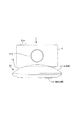
先ず、図1にデジタルスチルカメラ1の外観例を示す。図1(a)、(b)は、それぞれデジタルスチルカメラ1の正面図、背面図となる。
この図に示されるデジタルスチルカメラ1は、先ず、図1(a)に示すように、本体部2の前面側においてレンズ部21aを備える。このレンズ部21aは、撮像のための光学系として本体部2の外側に表出している部位である。
<1. Configuration of imaging system>
[1-1. overall structure]
The imaging system of this embodiment includes a digital
First, an example of the appearance of the digital
The digital
また、本体部2の上面部には、レリーズボタン31aが設けられている。撮像モードにおいてはレンズ部21aにより撮像された画像(撮像画像)が画像信号として生成される。そして、この撮像モードにおいてレリーズボタン31aに対する操作が行われると、この操作タイミングのときに得られていたとする撮像画像が、静止画の画像データとして記憶媒体に記録される。つまり、写真撮影が行われる。
A
また、デジタルスチルカメラ1は、図1(b)に示すようにして、その背面側に表示画面部33aを有する。
この表示画面部33aには、撮像モード時においては、スルー画などといわれ、そのときにレンズ部21aにより撮像している画像が表示される。また、再生モード時においては、記憶媒体に記録されている画像データが再生表示される。さらに、ユーザがデジタルスチルカメラ1に対して行った操作に応じて、GUI(Graphical User Interface)としての操作画像が表示される。
The digital
This
なお、本実施形態のデジタルスチルカメラ1は、表示画面部33aに対してタッチパネルが組み合わされているものとする。これにより、ユーザは、表示画面部33aに対して指を当てることによって、しかるべき操作を行うことができる。
In the digital
また、本実施形態の撮像システム(撮像装置)は、このデジタルスチルカメラ1としての撮像装置部と、次に説明する雲台10としての可動機構部から成るものとしているが、ユーザは、デジタルスチルカメラ1単体のみを使用しても、通常のデジタルスチルカメラと同じように、写真撮影を行うことができる。
In addition, the imaging system (imaging apparatus) of the present embodiment includes an imaging apparatus unit as the digital
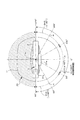
図2は、雲台10の外観を示す斜視図である。また、図3〜図6は、本実施形態の撮像システムの外観として、雲台10に対してデジタルスチルカメラ1が適切な状態で載置された状態を示している。図3は正面図、図4は平面図、図5は側面図であり、図6は側面図によりチルト機構の可動範囲を示したものである。
FIG. 2 is a perspective view showing the external appearance of the
図2、及び図3,図4,図5に示すように、雲台10は、大きくは接地台部15の上に本体部11が組み合わされたうえで、さらに本体部11に対してカメラ台座部12が取り付けられた構造を有する。
As shown in FIGS. 2, 3, 4, and 5, the
雲台10にデジタルスチルカメラ1を載置しようとするときには、デジタルスチルカメラ1の底面側を、カメラ台座部12の上面側に対して置くようにようにする。
この場合のカメラ台座部12の上面部には、図2に示すようにして、突起部13とコネクタ14が設けられている。
その図示は省略するが、デジタルスチルカメラ1の本体部2の下面部には、突起部13と係合する孔部が形成されている。デジタルスチルカメラ1がカメラ台座部12に対して適正に置かれた状態では、この孔部と突起部13とが係合した状態となる。この状態であれば、通常の雲台10のパンニング・チルティングの動作であれば、デジタルスチルカメラ1が雲台10からずれたり、外れてしまったりすることがないようにされている。
When the digital
In this case, a projection 13 and a connector 14 are provided on the upper surface of the
Although not shown in the drawings, a hole that engages with the protrusion 13 is formed on the lower surface of the
また、デジタルスチルカメラ1においては、その下面部の所定位置にもコネクタが設けられている。上記のようにして、カメラ台座部12にデジタルスチルカメラ1が適正に載置される状態では、デジタルスチルカメラ1のコネクタと雲台10のコネクタ14とが接続され、少なくとも、相互間の通信が可能な状態となる。
In the digital
なお、例えばコネクタ14と突起部13は、実際においては、カメラ台座部12において可動できるようになっている。そのうえで、例えばデジタルスチルカメラ1の底面部の形状に合わせたアダプタなどを併用することで、異なる機種のデジタルスチルカメラを、雲台10と通信可能な状態で、カメラ台座部12に載置できるようになっている。
また、デジタルスチルカメラ1とカメラ台座部12との通信は無線により行われるようにしてもよい。
For example, the connector 14 and the protrusion 13 are actually movable in the
In addition, communication between the digital
また、例えば雲台10に対してデジタルスチルカメラ1が載置された状態では、雲台10からデジタルスチルカメラ1に対して充電が行えるように構成しても良い。さらには、デジタルスチルカメラ1にて再生している画像などの映像信号を雲台10側にも伝送し、雲台10からさらにケーブルや無線通信などを介して、外部モニタ装置に出力させるような構成とすることも考えられる。つまり、雲台10について、単に、デジタルスチルカメラ1の撮像視野角を変更させるためだけに用いるのではなく、いわゆるクレードルとしての機能を与えることが可能である。
Further, for example, when the digital
なお、ここでの「撮像視野角」とは、定位置に置かれた撮像装置により撮像して得られる画像の画枠に収まる範囲について、上記の画角に加え、パン(水平)方向における振り角度と、チルト(垂直)方向における角度(仰角、俯角)の要素により決まるものをいう。 The “imaging viewing angle” here refers to a swing in the pan (horizontal) direction in addition to the angle of view described above for the range that fits in the image frame of an image obtained by imaging with an imaging device placed at a fixed position. This is determined by the elements of angle and angle (elevation angle, depression angle) in the tilt (vertical) direction.
次に、雲台10によるデジタルスチルカメラ1のパン・チルト方向の基本的な動きについて説明する。
まず、パン方向の基本的な動きは次のようになる。
この雲台10を床面などに置いた状態では、接地台部13の底面が接地する。この状態において、図4に示すように、回転軸11aを回転中心として、本体部11は時計回り方向、及び反時計回り方向に回転できるようになっている。これにより、雲台10に載置されているデジタルスチルカメラ1の撮像視野角は、左右方向(水平方向)に沿って変化することになる。つまり、パンニングの動きが与えられる。
そのうえで、この場合の雲台10のパン機構は、時計回り方向及び反時計回り方向の何れについても、360°以上の回転が無制限で自在に行える構造を有しているものとする。
Next, basic movement of the digital
First, the basic movement in the pan direction is as follows.
In a state where the
In addition, the pan mechanism of the pan /
また、この雲台のパン機構においては、パン方向における基準位置が決められている。
ここでは、図4に示すようにして、パン基準位置を0°(360°)としたうえで、パン方向に沿った本体部11の回転位置、即ちパン位置を0°〜360°により表すものとする。
In this pan head pan mechanism, a reference position in the pan direction is determined.
Here, as shown in FIG. 4, the pan reference position is set to 0 ° (360 °), and the rotation position of the
また、雲台10のチルト方向の基本的な動きについては次のようになる。
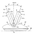
チルト方向の動きは、図5及び図6に示すようにして、カメラ台座部12が回転軸12aを回転中心として、仰角、俯角の両方向に可動することにより得られる。
ここで、図5は、カメラ台座部12がチルト基準位置Y0(0°)にある状態が示されている。この状態では、レンズ部21a(光学系部)の撮像光軸と一致する撮像方向F1と、接地台部13が接地する接地面部GRとが平行となる。
そのうえで、図6に示すように、先ず、仰角方向においては、カメラ台座部12は、回転軸12aを回転中心として、チルト基準位置Y0(0°)から所定の最大回転角度+f°の範囲で動くことができる。また、俯角方向においても、回転軸12aを回転中心として、チルト基準位置Y0(0°)から所定の最大回転角度−g°の範囲で動くことができるようになっている。このようにして、カメラ台座部12がチルト基準位置Y0(0°)を基点として、最大回転角度+f°〜最大回転角度−g°の範囲で動くことで、雲台10(カメラ台座部12)に載置されたデジタルスチルカメラ1の撮像視野角は、上下方向(垂直方向)沿って変化することになる。つまりチルティングの動作が得られる。
The basic movement of the
The movement in the tilt direction is obtained by moving the
Here, FIG. 5 shows a state in which the
In addition, as shown in FIG. 6, first, in the elevation direction, the
なお、図2〜図6に示した雲台10の外観構成はあくまでも一例であり、載置されたデジタルスチルカメラ1をパン方向及チルト方向に動かすことができるようにされていれば、他の物理的構成、構造が採られてもかまわない。
The external configuration of the
[1−2.デジタルスチルカメラ]
先ず、図7のブロック図は、デジタルスチルカメラ1の実際的な内部構成例を示している。
この図において、先ず、光学系部21は、例えばズームレンズ、フォーカスレンズなども含む所定枚数の撮像用のレンズ群、絞りなどを備えて成り、入射された光を撮像光としてイメージセンサ22の受光面に結像させる。
また、光学系部21においては、上記のズームレンズ、フォーカスレンズ、絞りなどを駆動させるための駆動機構部も備えられているものとされる。これらの駆動機構部は、例えば制御部27が実行するとされるズーム(画角)制御、自動焦点調整制御、自動露出制御などのいわゆるカメラ制御によりその動作が制御される。
[1-2. Digital still camera]
First, the block diagram of FIG. 7 shows a practical internal configuration example of the digital
In this figure, first, the
The
イメージセンサ22は、上記光学系部21にて得られる撮像光を電気信号に変換する、いわゆる光電変換を行う。このために、イメージセンサ22は、光学系部21からの撮像光を光電変換素子の受光面にて受光し、受光された光の強さに応じて蓄積される信号電荷を、所定タイミングにより順次出力する。これにより、撮像光に対応した電気信号(撮像信号)が出力される。なお、イメージセンサ22として採用される光電変換素子(撮像素子)としては、特に限定されるものではないが、現状であれば、例えばCMOSセンサやCCD(Charge Coupled Device)などを挙げることができる。また、CMOSセンサを採用する場合には、イメージセンサ22に相当するデバイス(部品)として、次に述べるA/Dコンバータ23に相当するアナログ−デジタル変換器も含めた構造とすることができる。
The
上記イメージセンサ22から出力される撮像信号は、A/Dコンバータ23に入力されることで、デジタル信号に変換され、信号処理部24に入力される。
信号処理部24では、A/Dコンバータ23から出力されるデジタルの撮像信号について、例えば1つの静止画 (フレーム画像)に相当する単位で取り込みを行い、このようにして取り込んだ静止画単位の撮像信号について所要の信号処理を施すことで、1枚の静止画に相当する画像信号データである撮像画像データ(撮像静止画像データ)を生成することができる。
The imaging signal output from the
In the
上記のようにして信号処理部24にて生成した撮像画像データを画像情報として記憶媒体(記憶媒体装置)であるメモリカード40に記録させる場合には、例えば1つの静止画に対応する撮像画像データを信号処理部24からエンコード/デコード部25に対して出力する。
エンコード/デコード部25は、信号処理部24から出力されてくる静止画単位の撮像画像データについて、所定の静止画像圧縮符号化方式により圧縮符号化を実行したうえで、例えば制御部27の制御に応じてヘッダなどを付加して、所定形式に圧縮された画像データの形式に変換する。そして、このようにして生成した画像データをメディアコントローラ26に転送する。メディアコントローラ26は、制御部27の制御に従って、メモリカード40に対して、転送されてくる画像データを書き込んで記録させる。この場合のメモリカード40は、例えば所定規格に従ったカード形式の外形形状を有し、内部には、フラッシュメモリなどの不揮発性の半導体記憶素子を備えた構成を採る記憶媒体である。なお、画像データを記憶させる記憶媒体については、上記メモリカード以外の種別、形式などとされてもよい。
When the captured image data generated by the
The encoding /
また、本実施の形態としての信号処理部24は、先の説明のようにして取得される撮像画像データを利用して、後述するように、被写体検出としての画像処理を実行させるように構成される。
In addition, the
また、デジタルスチルカメラ1は信号処理部24にて得られる撮像画像データを利用して表示部33により画像表示を実行させることで、現在撮像中の画像であるいわゆるスルー画を表示させることが可能とされる。例えば信号処理部24においては、先の説明のようにしてA/Dコンバータ23から出力される撮像信号を取り込んで1枚の静止画相当の撮像画像データを生成するのであるが、この動作を継続することで、動画におけるフレーム画像に相当する撮像画像データを順次生成していく。そして、このようにして順次生成される撮像画像データを、制御部27の制御に従って表示ドライバ32に対して転送する。これにより、スルー画の表示が行われる。
Further, the digital
表示ドライバ32では、上記のようにして信号処理部24から入力されてくる撮像画像データに基づいて表示部33を駆動するための駆動信号を生成し、表示部33に対して出力していくようにされる。これにより、表示部33においては、静止画単位の撮像画像データに基づく画像が順次的に表示されていくことになる。これをユーザが見れば、そのときに撮像しているとされる画像が表示部33において動画的に表示されることになる。つまり、スルー画が表示される。
The
また、デジタルスチルカメラ1は、メモリカード40に記録されている画像データを再生して、その画像を表示部33に対して表示させることも可能とされる。
このためには、制御部27が画像データを指定して、メディアコントローラ26に対してメモリカード40からのデータ読み出しを命令する。この命令に応答して、メディアコントローラ26は、指定された画像データが記録されているメモリカード40上のアドレスにアクセスしてデータ読み出しを実行し、読み出したデータを、エンコード/デコード部25に対して転送する。
The digital
For this purpose, the
エンコード/デコード部25は、例えば制御部27の制御に従って、メディアコントローラ26から転送されてきた撮像画像データから圧縮静止画データとしての実体データを取り出し、この圧縮静止画データについて、圧縮符号化に対する復号処理を実行して、1つの静止画に対応する撮像画像データを得る。そして、この撮像画像データを表示ドライバ32に対して転送する。これにより、表示部33においては、メモリカード40に記録されている撮像画像データの画像が再生表示されることになる。
The encode /
また表示部33に対しては、上記のスルー画や画像データの再生画像などとともに、ユーザインターフェース画像(操作画像)も表示させることができる。この場合には、例えばそのときの動作状態などに応じて制御部27が必要なユーザインターフェース画像としての表示用画像データを生成し、これを表示ドライバ32に対して出力するようにされる。これにより、表示部33においてユーザインターフェース画像が表示されることになる。なお、このユーザインターフェース画像は、例えば特定のメニュー画面などのようにモニタ画像や撮像画像データの再生画像とは個別に表示部33の表示画面に表示させることも可能であるし、モニタ画像や撮像画像データの再生画像上の一部において重畳・合成されるようにして表示させることも可能である。
Further, on the
制御部27は、例えば実際においてはCPU(Central Processing Unit)を備えて成るもので、ROM28、RAM29などとともにマイクロコンピュータを構成する。ROM28には、例えば制御部27としてのCPUが実行すべきプログラムの他、デジタルスチルカメラ1の動作に関連した各種の設定情報などが記憶される。RAM29は、CPUのための主記憶装置とされる。
また、この場合のフラッシュメモリ30は、例えばユーザ操作や動作履歴などに応じて変更(書き換え)の必要性のある各種の設定情報などを記憶させておくために使用する不揮発性の記憶領域として設けられるものである。なおROM28について、例えばフラッシュメモリなどをはじめとする不揮発性メモリを採用することとした場合には、フラッシュメモリ30に代えて、このROM28における一部記憶領域を使用することとしてもよい。
The
Further, the
操作部31は、デジタルスチルカメラ1に備えられる各種操作子と、これらの操作子に対して行われた操作に応じた操作情報信号を生成してCPUに出力する操作情報信号出力部位とを一括して示している。制御部27は、操作部31から入力される操作情報信号に応じて所定の処理を実行する。これによりユーザ操作に応じたデジタルスチルカメラ1の動作が実行されることになる。
The
雲台対応通信部34は、雲台10側とデジタルスチルカメラ1側との間での所定の通信方式に従った通信を実行する部位であり、例えばデジタルスチルカメラ1が雲台10に対して取り付けられた状態において、雲台10側の通信部との間での有線若しくは無線による通信信号の送受信を可能とするための物理層構成と、これより上位となる所定層に対応する通信処理を実現するための構成とを有して成る。上記物理層構成として、図2との対応では、コネクタ14と接続されるコネクタの部位が含まれる。
The pan
[1−3.雲台]
図8のブロック図は、雲台10の内部構成例を示している。
先に述べたように、雲台10は、パン・チルト機構を備えるものであり、これに対応する部位として、パン機構部53、パン用モータ54、チルト機構部56、チルト用モータ57を備える。
パン機構部53は、雲台10に取り付けられたデジタルスチルカメラ1について、図4に示したパン(横・左右)方向の動きを与えるための機構を有して構成され、この機構の動きは、パン用モータ54が正逆方向に回転することによって得られる。同様にして、チルト機構部56は、雲台10に取り付けられたデジタルスチルカメラ1について、図6に示したチルト(縦・上下)方向の動きを与えるための機構を有して構成され、この機構の動きは、チルト用モータ57が正逆方向に回転することによって得られる。
[1-3. Pan head]
The block diagram of FIG. 8 shows an example of the internal configuration of the
As described above, the
The
制御部51は、例えばCPU、ROM、RAMなどが組み合わされて形成されるマイクロコンピュータを有して成り、上記パン機構部53、チルト機構部56の動きをコントロールする。例えば制御部51がパン機構部53の動きを制御するときには、移動させるべき方向と移動速度を指示する信号をパン用駆動部55に対して出力する。パン用駆動部55は、入力される信号に対応したモータ駆動信号を生成してパン用モータ54に出力する。このモータ駆動信号は、例えばモータがステッピングモータであれば、PWM制御に対応したパルス信号となる。
このモータ駆動信号によりパン用モータ54が、例えば所要の回転方向、回転速度により回転し、この結果、パン機構部53も、これに対応した移動方向と移動速度により動くようにして駆動される。
同様にして、チルト機構部56の動きを制御するときには、制御部51は、チルト機構部56に必要な移動方向、移動速度を指示する信号をチルト用駆動部58に対して出力する。チルト用駆動部58は、入力される信号に対応したモータ駆動信号を生成してチルト用モータ57に出力する。このモータ駆動信号によりチルト用モータ57が、例えば所要の回転方向及び回転速度で回転し、この結果、チルト機構部56も、これに対応した移動方向,速度により動くようにして駆動される。
また、パン機構部53は、ロータリーエンコーダ(回転検出器)53aを備えている。ロータリーエンコーダ53aは、パン機構部53の回転の動きに応じて、その回転角度量を示す検出信号を制御部51に出力する。同様に、チルト機構部56はロータリーエンコーダ56aを備える。このロータリーエンコーダ56aも、チルト機構部56の回転の動きに応じて、その回転角度量を示す信号を制御部51に出力する。
The
By this motor drive signal, the
Similarly, when controlling the movement of the
The
通信部52は、雲台10に取り付けられたデジタルスチルカメラ1内の雲台対応通信部34との間で所定の通信方式に従った通信を実行する部位であり、雲台対応通信部34と同様にして、相手側通信部と有線若しくは無線による通信信号の送受信を可能とするための物理層構成と、これより上位となる所定層に対応する通信処理を実現するための構成とを有して成る。上記物理層構成として、図2との対応では、カメラ台座部12のコネクタ14が含まれる。
The
[1−4.撮像システムの機能構成例]
次に、図9のブロック図により、本実施形態に対応する撮像システムを成すデジタルスチルカメラ1及び雲台10についての、ハードウェア及びソフトウェア(プログラム)により実現される機能構成(システム構成)例を示す。
この図において、デジタルスチルカメラ1は、撮像記録ブロック61、構図判定ブロック62、パン・チルト・ズーム制御ブロック63、及び通信制御処理ブロック64を備えて成るものとされている。
[1-4. Functional configuration example of imaging system]
Next, referring to the block diagram of FIG. 9, an example of a functional configuration (system configuration) realized by hardware and software (program) for the digital
In this figure, the digital
撮像記録ブロック61は、撮像により得られた画像を画像信号のデータ(撮像画像データ)として得て、この撮像画像データを記憶媒体に記憶するための制御処理を実行する部位である。この部位は、例えば撮像のための光学系、撮像素子(イメージセンサ)、及び撮像素子から出力される信号から撮像画像データを生成する信号処理回路、また、撮像画像データを記憶媒体に書き込んで記録(記憶)させるための記録制御・処理系などを有して成る部位である。
この場合の撮像記録ブロック61における撮像画像データの記録(撮像記録)は、構図判定ブロック62の指示、制御により実行される。
The
In this case, the recording (imaging recording) of the captured image data in the
構図判定ブロック62は、撮像記録ブロック61から出力される撮像画像データを取り込んで入力し、この撮像画像データを基にして、先ず被写体検出を行い、最終的には構図判定のための処理を実行する。さらに、判定した構図による画内容の撮像画像データが得られるようにするための構図合わせ制御も実行する。
ここで、構図判定ブロック62が実行する被写体検出処理(初期顔枠の設定を含む)は、図7との対応では信号処理部24が実行するようにして構成できる。また、この信号処理部24による被写体検出処理は、DSP(Digital signal Processor)による画像信号処理として実現できる。つまり、DSPに与えるプログラム、インストラクションにより実現できる。
また、構図判定ブロック62が実行する顔枠の修正、及び構図判定、構図合わせ制御は、制御部27としてのCPUがプログラムに従って実行する処理として実現できる。
The
Here, the subject detection process (including initial face frame setting) executed by the
Further, the face frame correction, composition determination, and composition adjustment control executed by the
パン・チルト・ズーム制御ブロック63は、構図判定ブロック62の指示に応じて、判定された最適構図に応じた構図、撮像視野角が得られるように、パン・チルト・ズーム制御を実行する。つまり、構図合わせ制御として、構図判定ブロック62は、例えば判定された最適構図に応じて得るべき上記構図、撮像視野角をパン・チルト・ズーム制御ブロック63に指示する。パン・チルト・ズーム制御ブロック63は、指示された構図、撮像視野角が得られる撮像方向にデジタルスチルカメラ1が向くための、雲台10のパン・チルト機構についての移動量を求め、この求めた移動量に応じた移動を指示するパン・チルト制御信号を生成する。
また、例えば判定された適切画角を得るためのズーム位置を求め、このズーム位置となるようにして、撮像記録ブロック61が備えるとされるズーム機構を制御する。
The pan / tilt /
Further, for example, a zoom position for obtaining the determined appropriate angle of view is obtained, and the zoom mechanism that the
通信制御ブロック64は、雲台10側に備えられる通信制御ブロック71との間で所定の通信プロトコルに従って通信を実行するための部位となる。上記パン・チルト・ズーム制御ブロック63が生成したパン・チルト制御信号は、通信制御ブロック64の通信により、雲台10の通信制御ブロック71に対して送信される。
The
雲台10は、例えば図示するようにして、通信制御ブロック71、及びパン・チルト制御処理ブロック72を有している。
通信制御ブロック71は、デジタルスチルカメラ1側の通信制御ブロック64との間での通信を実行するための部位であり、上記のパン・チルト制御信号を受信した場合には、このパン・チルト制御信号をパン・チルト制御処理ブロック72に対して出力する。
The
The
パン・チルト制御処理ブロック72は、ここでは図示していない雲台10側のマイクロコンピュータなどが実行する制御処理のうちで、パン・チルト制御に関する処理の実行機能に対応するものとなる。
このパン・チルト制御処理ブロック72は、入力したパン・チルト制御信号に応じて、ここでは図示していないパン駆動機構部、チルト駆動機構部を制御する。これにより、最適構図に応じて必要な水平視野角と垂直視野角を得るためのパンニング、チルティングが行われる。
The pan / tilt
The pan / tilt
また、この場合の構図判定ブロック62は後述するようにして被写体検出処理を実行するが、この被写体検出のために、パン・チルト・ズーム制御ブロック63は、例えば指令に応じて被写体探索のためのパン・チルト・ズーム制御を行うことができるようになっている。
In this case, the
<2.被写体探索挙動例1>
上記のようにしてデジタルスチルカメラ1と雲台10から成る本実施形態の撮像システムは、パン・チルト・ズームの動きにより自動的に被写体探索を行って、例えば人物などとしての周囲の被写体を検出する。そして、被写体を検出すると、この検出した被写体を対象として構図を自動的に設定したうえで撮像記録を行う。
このような自動撮像記録動作においては、被写体探索を実行する際においてどのような探索の挙動とすべきか、即ち、パンニング・チルティングによる撮像方向(撮像光軸)の移動パターンをどのようなものとすべきかを考える必要がある。
<2. Subject Search Behavior Example 1>
As described above, the imaging system of the present embodiment including the digital
In such an automatic imaging and recording operation, what kind of search behavior should be performed when performing a subject search, that is, what is the movement pattern in the imaging direction (imaging optical axis) by panning / tilting. You need to think about what to do.
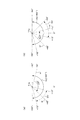
図10,図11は、被写体探索時の挙動として考え得る1例を示している。
先ず、パン方向の動きについては、図10に示すようにして、第1探索回転方向RT1として示すように、時計回り方向については360°回転させる。次に、第2探索回転方向RT2として示すように、反時計回り方向についても360°回転させる。この例では、パン方向の動きについては、この第1探索回転方向RT1による動きと、第2探索回転方向RT2による動きが組み合わされることになる。
10 and 11 show an example that can be considered as a behavior when searching for a subject.
First, the movement in the pan direction is rotated 360 ° in the clockwise direction as shown in FIG. 10 as the first search rotation direction RT1. Next, as shown as the second search rotation direction RT2 , the counterclockwise direction is also rotated 360 °. In this example, the movement in the pan direction is a combination of the movement in the first search rotation direction RT1 and the movement in the second search rotation direction RT2.
そのうえで、チルト方向の動きの組み合わせにより、二次元的な探索パターンとしては、図11に示す白抜きの矢印Sc1〜Sc9の順により動きながら被写体探索を行う。
先ず、ここでは、或るパン・チルト位置に対応した始点Stに位置している状態において被写体探索を開始させることになったとする。すると、雲台10は、矢印Sc1として示すように、この始点Stからパン位置360°(0°)/チルト位置+f°となるようにしてパンニング・チルティングを行う。このパン位置360°(0°)/チルト位置+f°が被写体探索の起点(探索起点P)となる。パン位置360°(0°)/チルト位置+f°は、図4,図6から理解されるように、撮像方向F1として、パン方向においてはパン基準位置を向き、チルト方向においては、+f°の仰角により上向きとなった状態である。
In addition, a subject search is performed while moving in the order of white arrows Sc1 to Sc9 shown in FIG. 11 as a two-dimensional search pattern by combining the movements in the tilt direction.
First, here, it is assumed that the subject search is started in a state where it is located at the start point St corresponding to a certain pan / tilt position. Then, as shown by an arrow Sc1, the
次に、雲台10は、矢印Sc2で示す動きをする。つまり、チルト位置+f°は維持した状態で、例えば、第2探索回転方向RT2としての動きにより、パン位置0°に移動する。つまり、反時計回りで360°回転して、同じパン位置360°(0°)に戻る。
Next, the
次に雲台10は、矢印Sc3として示すように、パン位置0°(360°)において、チルト位置+f°からチルト位置0°となるようにして、チルティングを行う。これにより、撮像方向F1は、パン基準位置にて水平となる。
続いて雲台10は、チルト位置0°の状態で、矢印Sc4として示すように、第1探索回転方向RT1により360°のパンニングを行う。
次に雲台10は、矢印Sc5として示すように、チルト位置0°からチルト位置-g°となるようにしてチルティングを行う。
次に雲台10は、矢印Sc6として示すように、チルト位置-g°の状態で、第2探索回転方向により360°のパンニングを行う。
次に雲台10は、矢印Sc7として示すように、パン位置0°(360°)の状態で、チルト位置-g°からチルト位置0°に移動するようにしてチルティングを行う。
次に雲台10は、矢印Sc8として示すように、チルト位置0°を維持して第1探索回転方向RT1により360°回転するパンニングを行う。
次に雲台10は、矢印Sc9として示すように、パン位置360°(0°)を維持して、チルト位置0°からチルト位置+f°に移動するようにしてチルティングを行う。
上記矢印Sc9に対応するチルティングを終了すると、探索パターンとしては一巡したことになる。図11から分かるように、矢印Sc2〜Sc9による動きを一巡させた段階では、パン方向における正面(パン基準位置)での上下方向(+f°〜−g°)と、上側(チルト位置+f°)、中央(チルト位置0°)、下側(チルト位置-g°)のそれぞれでの360°方向との探索が網羅されることになる。
そして、以降は、同様にして、矢印Sc2〜Sc9に対応するパンニング、チルティングの動きを順次実行し、これを繰り返すようにする。この過程において被写体が検出されたのであれば、デジタルスチルカメラ1は、構図合わせ制御を行ったうえで撮像記録を実行する。例えばこの検出した被写体について、しかるべき構図で必要枚数を撮像記録したとすると、再度、探索起点Pであるパン位置360°(0°)/チルト位置+f°に戻り、矢印Sc2〜Sc9のパターンによる被写体探索を繰り返していくようにする。
Next, as shown by the arrow Sc3, the
Subsequently, the
Next, as shown by an arrow Sc5, the
Next, as shown by an arrow Sc6, the
Next, as shown by an arrow Sc7, the
Next, as shown by the arrow Sc8, the
Next, as shown by the arrow Sc9, the
When the tilting corresponding to the arrow Sc9 is completed, the search pattern is completed. As can be seen from FIG. 11, at the stage where the movements by the arrows Sc2 to Sc9 are completed, the vertical direction (+ f ° to −g °) at the front (pan reference position) in the pan direction and the upper side (tilt position + f °), center (tilt position 0 °), and lower (tilt position -g °) search in 360 ° directions are covered.
Thereafter, similarly, panning and tilting motions corresponding to the arrows Sc2 to Sc9 are sequentially executed and repeated. If a subject is detected in this process, the digital
<3.被写体探索挙動例2:実施形態としての二次元探索パターン>
[3−1.第1例]
本実施形態としては、上記図10、図11により説明した探索パターンを改善して、より効率よく被写体が探索できるようにした探索パターンを提案する。その第1例について、図12により説明する。
<3. Subject Search Behavior Example 2: Two-dimensional Search Pattern as Embodiment>
[3-1. First example]
In the present embodiment, a search pattern is proposed in which the search pattern described with reference to FIGS. 10 and 11 is improved so that a subject can be searched more efficiently. The first example will be described with reference to FIG.
先ず、本実施形態の探索パターンとしては、先ず、水平探索角αを設定する。この水平探索角αは、以降の説明のようにして、パン方向における動きのパターンなどに応じて変化し得る。最も基本的な水平探索角αの設定としては、α=360°とした場合を挙げることができる。
また、この図12の探索パターンでは、水平探索角αにおける中央位置を水平中心位置Hとして扱う。この水平中心位置Hを0°として、パン方向の可動範囲としては、 +α/2〜0°〜-α/2 として表す。
First, as a search pattern of this embodiment, first, a horizontal search angle α is set. The horizontal search angle α can be changed according to the movement pattern in the pan direction and the like as described below. As the most basic setting of the horizontal search angle α, there can be mentioned a case where α = 360 °.
In the search pattern of FIG. 12, the center position at the horizontal search angle α is treated as the horizontal center position H. The horizontal center position H is set to 0 °, and the movable range in the pan direction is expressed as + α / 2 to 0 ° to −α / 2.
図12に示される探索パターンは、次のようになる。なお、ここでの探索パターンについての具体的説明にあたっては、水平探索角α=360°とされている場合について述べる。
ここで、始点Stに対応する或るパン位置、チルト位置の状態において、被写体探索を開始すべきことになったとする。すると、雲台10は、白抜きの矢印Sc1として示すように、始点Stの位置から、パン位置はそのまま維持して、チルト方向のみについて、チルト位置+f°まで移動する。この始点Stに対応するパン位置におけるチルト位置+f°が、この場合の探索起点Pとなる。
図11の場合には、パン位置360°(0°)/チルト位置+f°としての絶対的な位置を探索起点Pとして規定していた。これに対して、図12の場合には、始点Stが対応するパン位置におけるチルト位置+f°を探索起点Pとする。つまり、本実施形態における探索起点Pにおけるパン位置は、始点Stの位置に応じて変化する。
The search pattern shown in FIG. 12 is as follows. In the specific description of the search pattern here, a case where the horizontal search angle α is set to 360 ° will be described.
Here, it is assumed that the subject search should be started in a certain pan position and tilt position corresponding to the start point St. Then, as shown by a white arrow Sc1, the
In the case of FIG. 11, the absolute position as pan position 360 ° (0 °) / tilt position + f ° is defined as the search starting point P. On the other hand, in the case of FIG. 12, the search starting point P is the tilt position + f ° at the pan position corresponding to the start point St. That is, the pan position at the search starting point P in the present embodiment changes according to the position of the start point St.
図12において探索起点Pに至ると、雲台10は、白抜きの矢印Sc2として示すように、チルト位置+f°は維持したうえで、パン方向の動きとして水平中心位置H(0°)から-2/α°まで移動させるパンニングを行う。次に、雲台10は、矢印Sc3として示すように、チルト位置+f°は維持したうえで、パン位置-2/α°から他方の限界であるパン位置+2/αまで移動させるパンニングを行う。次に、雲台10は、チルト位置+f°は維持したうえで、パン位置+2/αから水平中心位置H(0°)までパンニングを行う。
When reaching the search starting point P in FIG. 12, the
水平探索角α=360°とした場合、上記矢印Sc2〜Sc4までの動作については、例えば、デジタルスチルカメラ1が+f°のチルト位置を固定した状態で、先ず、水平中心位置から反時計回り方向(第2探索回転方向RT2)で180°回転し、次に、時計回り方向(第1探索回転方向RT1)で360°回転し、次に、反時計回り方向で180°回転して、水平中心位置Hに戻る、というものになる。
ここで、この1つの規定のチルト位置で固定した状態でのパン方向の探索動作に付いてみると、矢印Sc3の動きにより、時計回り方向(第1探索回転方向RT1)で360°の片道分の移動を行っている。また、矢印Sc2と矢印Sc4との動きにより、結果的には、反時計回り方向(第2探索回転方向RT2)で同様に360°の片道分の移動を行っているといえる。従って、矢印Sc2,Sc3,Sc4によっては、パン方向おける規定の回転角度範囲を一往復しているということがいえる。例えば、片道分の探索としてもよいのであるが、この図12の例では、往復の探索動作とすることで、より的確に被写体が検出されるようにしている。
そして、この矢印Sc2〜Sc4までの動作により、まずは、撮像方向F1が上向きのチルト位置+f°の状態でのパン方向の探索が完結したことになる。
When the horizontal search angle α is set to 360 °, the operations from the arrows Sc2 to Sc4 are, for example, counterclockwise from the horizontal center position with the digital
Here, with regard to the search operation in the pan direction in a state where it is fixed at this one specified tilt position, a one-way portion of 360 ° in the clockwise direction (first search rotation direction RT1 ) is caused by the movement of the arrow Sc3. Is moving. Further, due to the movement of the arrow Sc2 and the arrow Sc4, as a result, it can be said that the one-way movement of 360 ° is similarly performed in the counterclockwise direction (second search rotation direction RT2 ). Therefore, it can be said that the arrows Sc2, Sc3, and Sc4 reciprocate once within the specified rotation angle range in the pan direction. For example, a one-way search may be performed, but in the example of FIG. 12, a subject is detected more accurately by performing a reciprocal search operation.
With the operations from the arrows Sc2 to Sc4, first, the search in the pan direction in the state where the imaging direction F1 is the upward tilt position + f ° is completed.
次に雲台10は、矢印Sc5として示すように、水平中心位置H(0°)は維持したうえで、チルト位置+f°からチルト位置0°に移動させるチルティングを行う。これにより、撮像方向F1は上下における中央(水平)を向くことになる。
そのうえで、雲台10は、矢印Sc6、矢印Sc7、矢印Sc8として示すように、上記矢印Sc2,Sc3,Sc4と同様のパンニングを行う。これにより、撮像方向F1が上下方向において中央(水平)を向いた状態での、パン方向における一往復分の探索が完結したことになる。
Next, as shown by the arrow Sc5, the
Then, the
次に雲台10は、矢印Sc9として示すように、水平中心位置H(0°)は維持したうえで、チルト位置0°からチルト位置-g°に移動させるチルティングを行う。これにより、撮像方向F1は下を向くことになる。
そのうえで、雲台10は、矢印Sc10、矢印Sc11、矢印Sc12として示すように、上記矢印Sc2,Sc3,Sc4と同様のパンニングを行う。これにより、撮像方向F1が下を向いた状態での、パン方向における一往復分の探索が完結したことになる。
Next, as shown by an arrow Sc9, the
In addition, the
これまでの説明によると、図12に示す探索パターンでは、先ず、被写体探索開始時において得られていたパン位置が、そのまま探索起点Pのパン位置として設定される。
これは、例えば次のような利点がある。ここで、デジタルスチルカメラ1を載置した雲台10のパン位置がパン基準位置ではない状態にあるとする。そして、この状態において、雲台10を置き直し、被写体探索を開始させたとする。このような場合、ユーザは、無意識であっても、デジタルスチルカメラ1の撮像方向F1が自分の方にほぼ向くようにして置く可能性が高いといえる。このようなことを想定した場合、本実施形態のように、探索起点Pのパン位置としては、被写体探索開始時における雲台10のパン位置とすれば、先ず、雲台10を置き直したユーザがすぐに探索される可能性が高くなる。これに対して、図11の場合のように、絶対的な位置として設定された探索起点Pに戻したうえで探索を開始させた場合には、雲台10を置き直したユーザが探索されるまでには、より多くの時間を要する可能性が高い。
According to the description so far, in the search pattern shown in FIG. 12, the pan position obtained at the start of the subject search is set as the pan position of the search start point P as it is.
This has the following advantages, for example. Here, it is assumed that the pan position of the
また、上記したことからすれば、被写体となる人物は、少なくとも、パン方向においては、探索起点Pに対応した水平中心位置Hの近傍にいる可能性が高いといえる。そこで、図12の探索パターンとしては、上下方向に撮像方向F1を変化させるためにパンニングを行う際には、必ず、水平中心位置Hにて行うようにしている。 From the above, it can be said that the person who is the subject is highly likely to be in the vicinity of the horizontal center position H corresponding to the search start point P at least in the pan direction. Therefore, as the search pattern of FIG. 12, when panning is performed in order to change the imaging direction F1 in the vertical direction, the search is always performed at the horizontal center position H.
さらに、本願発明者は、いくつかの状況を想定して検討したところ、撮像方向が上向きのときのほうが、被写体となる人物の顔が画枠内に存在して検出される確率が高いことを確認した。これは、一般的な傾向として、ユーザが、自動撮影記録のためにデジタルスチルカメラ1が載せられた状態の雲台10を置こうとした場合、その場所は、被写体となる人物達が囲んでいるテーブルであるような場合が多い。また、被写体となる人物が主に立っているような状態であれば、胸から腰の高さあたりの台などが多くなる。つまり、高さの関係としては、被写体となる人物の顔のほうが、デジタルスチルカメラ1よりも高くなる傾向となる。
そこで、図12の探索パターンでは、パン方向での探索については、例えば先ず、撮像方向を上向きとしたうえでパン方向に探索し、(Sc2,Sc3,Sc4)、次いで、同様の探索を、中央(水平)(Sc6,Sc7,Sc8)、下(Sc10,Sc11,Sc12)の順により行うこととしている。つまり、チルト位置固定によるパン方向の探索を、撮像方向F1が上向きの状態から、順次、下向きの状態となるようにしてチルト位置を変更しながら行っていく。
このようにして、図12に示す探索パターンは、できるだけ短時間で効率よく被写体が検出されるように配慮されている。
なお、ここでは、固定されるチルト位置について、+f°、0°、-g°に応じた3段階としているが、これはあくまでも一例であって、2段階以上であれば、+f°〜-g°の範囲において、任意の段階数によるチルト位置を設定してよい。また、設定される複数のチルト位置も、必ずしも等角度で分割する必要はなく、例えば上向きのチルト位置について、下向きのチルト位置よりも小さい分割角度を設定するなど、分割角度に変化を与えてもよい。
Furthermore, the inventor of the present application has considered a number of situations and found that when the imaging direction is upward, there is a higher probability that the face of the person who is the subject will be detected in the image frame. confirmed. This is because, as a general tendency, when the user tries to place the
Therefore, in the search pattern of FIG. 12, for the search in the pan direction, for example, first, the image pickup direction is set upward, the search is performed in the pan direction, (Sc2, Sc3, Sc4), and then the similar search is performed in the center. (Horizontal) (Sc6, Sc7, Sc8), down (Sc10, Sc11, Sc12). In other words, the pan direction search by fixing the tilt position is performed while changing the tilt position so that the imaging direction F1 is sequentially changed from the upward direction to the downward direction.
In this way, the search pattern shown in FIG. 12 is designed so that the subject can be detected efficiently in the shortest possible time.
Here, the fixed tilt position has three steps according to + f °, 0 °, and −g °. However, this is merely an example, and if it is two or more steps, + f ° ˜ In the range of -g °, the tilt position by an arbitrary number of steps may be set. Also, it is not always necessary to divide a plurality of set tilt positions at equal angles. For example, for an upward tilt position, a division angle smaller than the downward tilt position may be set. Good.
[3−2.第2例]
図13は、本実施形態の二次元探索パターンの第2例であり、図12の二次元探索パターンを基としたうえで、より簡略なパターンとした場合を示している。
図13においても、被写体探索のパターン開始時は、始点Stが対応するパン位置を水平中心位置Hとしたうえで、矢印Sc1として示すように、この水平中心位置Hにおいてチルト位置+f°まで移動させるチルティングを行う。これにより、撮像方向F1は上向きとなる。
次に雲台10は、矢印Sc2として示すように、チルト位置+f°を維持してパン位置-α/2まで180°のパンニングを行う。次に雲台10は、矢印Sc3として示すように、パン位置-α/2からパン位置+α/2まで360°回転するパンニングを行う。これにより、撮像方向F1が上向きの状態での左右方向の探索が完了したことになる。矢印Sc2と矢印Sc3によっては、完全に一往復とはなっていない。第1例では、固定されチルト位置ごとにおけるパン方向の動きは必ず一往復となるようにされていたが、第2例では、簡略化のために、少なくとも時計回り方向若しくは反時計回り方向の一方による片道の探索が行われれば、1つの固定チルト位置でのパン方向の探索は完了したものとして扱う。
[3-2. Second example]
FIG. 13 is a second example of the two-dimensional search pattern of the present embodiment, and shows a simpler pattern based on the two-dimensional search pattern of FIG.
Also in FIG. 13, at the start of the subject search pattern, the pan position corresponding to the start point St is set to the horizontal center position H and then moved to the tilt position + f ° at the horizontal center position H as shown by the arrow Sc1. Perform tilting. Thereby, the imaging direction F1 is upward.
Next, as shown by the arrow Sc2, the
次に雲台10は、矢印Sc4として示すように、パン位置+α/2を維持して、チルト位置+f°からチルト位置0°まで移動させるチルティングを行う。これにより撮像方向F1は、上向きから中央向きに移動したことになる。次に、雲台10は、矢印Sc5として示すように、チルト位置0°の状態で、パン位置+α/2からパン位置-α/2までの360°のパンニングを行う。これにより、撮像方向F1が上下方向における中央を向いた状態でのパン方向の探索が完了したことになる。
次に雲台10は、矢印Sc6として示すように、パン位置-α/2にて、チルト位置0°からチルト位置-g°に移動させるチルティングを行い、撮像方向F1を下向きとする。次に雲台10は、矢印Sc7として示すように、チルト位置-g°のまま、パン位置-α/2からパン位置+α/2まで360°回転させるパンニングを行う。これにより、撮像方向F1が下向きでのパン方向における片道分の探索が完了する。
Next, as shown by an arrow Sc4, the
Next, as shown by the arrow Sc6, the
次に雲台10は、矢印Sc8として示すように、パン位置+α/2にて、チルト位置-g°からチルト位置0°に移動させるチルティングを行い、さらに、矢印Sc9として示すように、再度、チルト位置0°にて、パン位置+α/2からパン位置-α/2までの360°の回転によるパンニングを行う。
次に、雲台10は、矢印Sc10として示すように、パン位置-α/2にて、チルト位置0°からチルト位置+f°まで移動させるチルティングを行い、さらに、矢印Sc11として示すように、チルト位置+f°にて、パン位置-α/2から水平中心位置H(0°)にまで移動させるパンニングを行う。これにより、探索パターンを一巡し、パン・チルト位置は探索起点Pに戻ったことになる。
Next, the
Next, the
この図13と、先の図12とを比較すると、図13のほうが、一巡の二次元探索パターンにおけるパンニング・チルティングによる移動量は少なくなっている。これにより、図13のほうが探索パターンを一巡させる時間は短縮することができ、これに応じて、例えばより短時間で被写体を探索することも可能になる。
ただし、図13の例では、探索パターンを簡易化するために、撮像方向F1の上下方向における向きを変更するのにあたっては、水平中心位置Hにて行うのではなく、パン位置±α/2にて行うようにしている。しかし、本実施形態としては、被写体の存在する確率としてみた場合には、水平方向における撮像方向F1よりも、上下方向における撮像方向F1のほうを重視することとしている。このために、図12においても、左右方向の探索については、図13と同様に、上、中央、下の順で行うようにしている。このようにして、第2例では、探索パターンを一巡させる時間の短縮と、実用上十分とされる探索性能とを両立させようとしている。
Comparing FIG. 13 with the previous FIG. 12, the amount of movement due to panning / tilting in a round two-dimensional search pattern is smaller in FIG. As a result, the time for making a round of the search pattern in FIG. 13 can be shortened, and the subject can be searched in a shorter time, for example.
However, in the example of FIG. 13, in order to simplify the search pattern, the vertical direction of the imaging direction F1 is not changed at the horizontal center position H, but at the pan position ± α / 2. To do. However, in the present embodiment, when viewed as the probability that a subject exists, the imaging direction F1 in the vertical direction is more important than the imaging direction F1 in the horizontal direction. Therefore, also in FIG. 12, the search in the left-right direction is performed in the order of top, center, and bottom as in FIG. In this way, in the second example, an attempt is made to achieve both a reduction in the time required for making a round of search patterns and a practically sufficient search performance.
なお、本実施形態の探索パターンの第1例、第2例として、図12,図13にて説明した、+α/2,-α/2と実際のパン方向における移動方向との対応は、逆とされてもよい。つまり、図12についての先の説明では、矢印Sc2などとして示す紙面左側へのパン移動方向は反時計回り方向、矢印Sc3などとして示す紙面右側へのパン移動方向は時計回し方向、としている。これとは反対に、矢印Sc2などが時計回り方向、矢印Sc3などが反時計回り方向となるパン方向とされてよい。 As a first example and a second example of the search pattern of the present embodiment, the correspondence between + α / 2, −α / 2 and the movement direction in the actual pan direction described with reference to FIGS. It may be reversed. That is, in the above description of FIG. 12, the pan movement direction to the left side of the drawing indicated by the arrow Sc2 or the like is the counterclockwise direction, and the pan movement direction to the right side of the drawing indicated by the arrow Sc3 or the like is the clockwise direction. On the contrary, the pan direction in which the arrow Sc2 or the like is the clockwise direction and the arrow Sc3 or the like is the counterclockwise direction may be used.
<4.被写体探索挙動例3:実施形態としての部分探索範囲設定(第1例)>
[4−1.回転角度の制限無しの場合]
これまでの説明では、本実施形態としての図12若しくは図13の探索パターンを一巡させるのにあたり、パン方向の最大移動範囲、即ち、水平探索角αについては360°であるとしていた。
本実施形態では、より効率よく被写体探索が行えるようにするために、例えば、水平探索角αを360°より小さい所定角度で分割し、この分割された水平探索角α(部分角度値)ごとに、例えば図12,図13に示した探索パターンによる探索を行っていくという構成を提案する。
なお、この水平探索角αを分割した被写体探索においては、例えば図11に示した探索パターンも適用できる。ただし、図12,図13としての本実施形態の探索パターンを採用することで、より効率的な被写体探索が可能になる。以降の説明においては、便宜上、分割された水平探索角αごとに、図12に示した本探索パターンが適用されていることを前提とする。
<4. Subject Search Behavior Example 3: Partial Search Range Setting as First Embodiment (First Example)>
[4-1. When there is no limit of rotation angle]
In the description so far, the maximum movement range in the pan direction, that is, the horizontal search angle α is 360 ° in making a round of the search pattern of FIG. 12 or FIG. 13 as the present embodiment.
In the present embodiment, in order to perform subject search more efficiently, for example, the horizontal search angle α is divided by a predetermined angle smaller than 360 °, and each divided horizontal search angle α (partial angle value) is divided. For example, a configuration is proposed in which a search is performed according to the search pattern shown in FIGS.
For example, the search pattern shown in FIG. 11 can also be applied to the subject search in which the horizontal search angle α is divided. However, by adopting the search pattern of the present embodiment as shown in FIGS. 12 and 13, a more efficient subject search can be performed. In the following description, for the sake of convenience, it is assumed that the search pattern shown in FIG. 12 is applied to each divided horizontal search angle α.
先ず、水平探索角αを分割した被写体探索の最も基本的な例として、雲台10のパン方向における回転角度に制限が無い場合の探索動作例について、図14を参照して説明する。
First, as a most basic example of the subject search in which the horizontal search angle α is divided, a search operation example in the case where there is no limitation on the rotation angle of the
図14においては、360°のパン角度について、第1部分探索範囲DV1〜第4部分探索範囲DV4の4つの部分探索範囲(パン方向の可動角度範囲)に分割している。ここでは、4つの部分探索範囲は等角度で分割することとしている。つまり、1つの部分探索範囲が有するパン方向の角度範囲は90°である。そして、これら第1〜第4部分探索範囲DV1〜DV4の各々が有するパン方向の角度範囲90°が、水平探索角αに相当する。
In FIG. 14, the pan angle of 360 ° is divided into four partial search ranges (movable angle range in the pan direction) of the first partial search range DV1 to the fourth partial search range DV4. Here, the four partial search ranges are divided at equal angles. That is, the angle range in the pan direction of one partial search range is 90 °. The panning
なお、本実施形態の図12、図13に示す探索パターンでは、先に述べたように、水平中心位置Hは、被写体探索開始時のパン位置に応じて決まる。従って、第1部分探索範囲DV1〜第4部分探索範囲DV4の各水平中心位置Hは、90°おきの間隔で、0°〜360°のパン角度範囲におけるどのパン位置にも設定され得る。しかし、図14においては、図示及び説明を簡単で分かりやすいものとすることの都合上、第1部分探索範囲DV1の水平中心位置Hが、パン基準位置と一致している場合を示している。 In the search patterns shown in FIGS. 12 and 13 of the present embodiment, as described above, the horizontal center position H is determined according to the pan position at the start of the subject search. Accordingly, the horizontal center positions H of the first partial search range DV1 to the fourth partial search range DV4 can be set at any pan position in the pan angle range of 0 ° to 360 ° at intervals of 90 °. However, FIG. 14 shows a case where the horizontal center position H of the first partial search range DV1 coincides with the pan reference position for the sake of simplicity and illustration.
この図14に示されるように第1〜第4部分探索範囲DV1〜DV4を規定した場合の被写体探索の挙動については、次のようになる。
先ず、雲台10は、第1部分探索範囲DV1のパン角度範囲において、図12の二次元探索パターンを一巡させる。このとき、図12における水平中心位置Hは、パン位置0°となる。また、図12における+α/2はパン位置45°が対応し、-α/2は、パン位置315°が対応する。つまり、この場合の第1部分探索範囲DV1は、パン位置315°〜(0°)〜45°の角度位置範囲にて設定されている。
第1部分探索範囲DV1にて図12の二次元探索パターンを一巡させると、続いては、雲台10は、撮像方向F1がパン位置90°となるようにしてパン方向に移動させる。パン位置+45°は、図示するようにして、第2部分探索範囲DV2のパン角度範囲における水平中心位置Hである。そこで、雲台10は、第2部分探索範囲DV2にて図12の二次元探索パターンを一巡させる。
以降、雲台10は、同様にして、第3部分探索範囲DV3における水平中心位置Hであるパン位置180°にまで移動して、第3部分探索範囲DV3にて図12の二次元探索パターンを一巡させる。次に、第4部分探索範囲DV4における水平中心位置Hであるパン位置270°にまで移動して、第4部分探索範囲DV4にて図12の二次元探索パターンを一巡させる。
このようにして、第1部分探索範囲DV1、第2部分探索範囲DV2、第3部分探索範囲DV3、第4部分探索範囲DV4の順で図12の二次元探索パターンを一巡させることで、探索可能範囲の全てを網羅した被写体探索が一巡することになる。以降は、上記第1部分探索範囲DV1〜第4部分探索範囲DV4の順で図12の二次元探索パターンを一巡させるという探索動作を繰り返す。
The subject search behavior when the first to fourth partial search ranges DV1 to DV4 are defined as shown in FIG. 14 is as follows.
First, the
When the two-dimensional search pattern of FIG. 12 is made a round in the first partial search range DV1, the pan /
Thereafter, the
In this way, the search can be performed by making a round of the two-dimensional search pattern of FIG. 12 in the order of the first partial search range DV1, the second partial search range DV2, the third partial search range DV3, and the fourth partial search range DV4. The subject search covering the entire range is completed. Thereafter, the search operation of making a round of the two-dimensional search pattern of FIG. 12 in the order of the first partial search range DV1 to the fourth partial search range DV4 is repeated.
そして、上記の探索動作のもと、例えば第1部分探索範囲DV1に含まれる或るパン・チルト位置にて被写体が探索されたとする。これに応じては、例えばデジタルスチルカメラ1により構図合わせ制御を行って撮像記録を行うようにする。そして、例えば必要枚数分の撮像記録が完了したとすると、次の第2部分探索範囲DV2に移動して探索動作を引き続き実行する。
Then, it is assumed that the subject is searched for at a certain pan / tilt position included in the first partial search range DV1, for example, under the search operation described above. In response to this, for example, the digital
[4−2.回転角度の制限有りの場合:有効回転角度180°]
ところで、上記図14に示した例は、雲台10のパン方向における回転角度(有効探索範囲(有効可動角度範囲))に制限が無い場合に対応する。この場合、図14の説明から理解されるように、撮像システムは、デジタルスチルカメラ1を結果的にはパン方向において360°以上で制限無く回転し、被写体を探索して撮像することになる。しかし、実際の使用を考慮した場合、状況によっては、このような動作は好ましくない場合がある。
例として、レストランなどで使用する場合、パン方向において360°以上で回転して被写体探索を行うと、他のテーブルにいる全く関係ない他人まで撮像記録してしまうことになる。
また、家庭などで、テレビジョン受像機の前に本実施形態の撮像システムを置いて、テレビジョン受像機に表示されている画像を鑑賞している家族を自動撮影しようとする場合を考えてみる.この場合、撮像システムの後ろ半分ではテレビジョン受像機を撮影することになってしまうから、パン方向に360°以上で回転して被写体探索を行わせたまままでは、その探索動作に無駄が多くなる。
[4-2. When rotation angle is limited: Effective rotation angle 180 °]
Incidentally, the example shown in FIG. 14 corresponds to a case where the rotation angle (effective search range (effective movable angle range)) of the
As an example, when used in a restaurant or the like, if a subject search is performed by rotating at 360 ° or more in the pan direction, even an unrelated person at another table is recorded and recorded.
Also, consider a case in which an imaging system according to the present embodiment is placed in front of a television receiver at home or the like to automatically photograph a family watching an image displayed on the television receiver. . In this case, since the television receiver is photographed in the rear half of the imaging system, there is a lot of waste in the search operation until the subject search is performed by rotating 360 ° or more in the pan direction. Become.
そこで、本実施形態では、雲台10がパン方向において被写体探索のために回転可能な最大角度(有効探索範囲)を制限できるようにする。本実施形態としては、先ず、有効探索範囲を制限するか否かについて、デジタルスチルカメラ1に対する操作によりユーザが選択設定できるようにされているものとする。また、有効探索範囲を制限することとした場合には、その有効探索範囲としての角度を複数の選択肢のうちから選択できるようにする。この場合において、選択肢としては、いくつ用意されてもよいのであるが、ここでは、180°と90°の2つの選択肢があるものとする。
つまり、本実施形態としては、有効探索範囲について、[1]無制限、[2]制限有り:180°、[3]制限有り90°の3つの選択肢のうちからユーザが選択する操作が行えるようにされている。
Therefore, in the present embodiment, it is possible to limit the maximum angle (effective search range) that the
That is, according to the present embodiment, the effective search range can be operated by the user to select from three options: [1] Unlimited, [2] Restricted: 180 °, [3] Restricted 90 °. Has been.
また、本実施形態の雲台10が、デジタルスチルカメラ1のクレードルとしても機能する構成とされている場合、雲台10には、ACアダプタであるとか、映像信号用ケーブルなどが接続される場合がある。
一具体例として、雲台10の背面側にACアダプタ端子や映像出力端子ジャックを設けることとする。これらの端子ジャックに対してプラグが差し込まれている場合においては、有効探索範囲を無制限にすると、端子と接続されているケーブルが不用意に引き回されてじゃまになる。そこで、撮像システムとしては、雲台10の端子ジャックに対してプラグが差し込まれことを検知できるようにして、雲台10の端子ジャックに対してプラグが差し込まれている状態のときには、自動的に、有効探索範囲を180°、若しくは90°で制限するようにして設定する。
Further, when the
As a specific example, an AC adapter terminal and a video output terminal jack are provided on the back side of the
図15は、有効探索範囲VLの角度を180°に制限して設定した場合に対応する、部分探索範囲の設定態様例を示している。
この図では、180°の有効探索範囲VLを、第1部分探索範囲DV1、第2部分探索範囲DV2、第3部分探索範囲DV3の3つに分割している。これに応じて、第1部分探索範囲DV1、第2部分探索範囲DV2、第3部分探索範囲DV3の水平探索角αは、それぞれ60°として設定される。
FIG. 15 shows a partial search range setting example corresponding to the case where the angle of the effective search range VL is set to 180 °.
In this figure, the effective search range VL of 180 ° is divided into three parts, a first partial search range DV1, a second partial search range DV2, and a third partial search range DV3. Accordingly, the horizontal search angles α of the first partial search range DV1, the second partial search range DV2, and the third partial search range DV3 are each set to 60 °.
仮に図14の部分探索範囲の設定に従って、そのまま単純に有効探索範囲VL=180°とした場合には、水平探索角α=90°の部分探索範囲を2つ設定すべきことになる。しかし、有効探索範囲が制限されることになれば、それだけパン方向において探索すべき範囲は狭くなるから、それだけ全探索可能範囲の探索を一巡する時間は短くなる。例えば、図14に示した有効探索範囲が無制限の場合において得られる探索時間が実用上問題にならない程度に短くなっていれば、有効探索範囲を制限したときには、より丹念に被写体探索を行ってもよい、ということがいえる。 If the effective search range VL = 180 ° is simply set as it is in accordance with the setting of the partial search range in FIG. 14, two partial search ranges with the horizontal search angle α = 90 ° should be set. However, if the effective search range is limited, the range to be searched in the pan direction is narrowed accordingly, so that the time for making a round of searching the entire searchable range is shortened accordingly. For example, if the search time obtained in the case where the effective search range shown in FIG. 14 is unlimited is shortened to such an extent that it does not cause a problem in practice, the subject search can be performed more carefully when the effective search range is limited. It can be said that it is good.
そこで、有効探索範囲VLの角度が180°として設定された場合には、図15に示すようにして、部分探索範囲の数については、2より多い3を設定し、これに伴って1つの部分探索範囲の水平探索角αについては、図14の場合よりも小さい60°としたものである。 Therefore, when the angle of the effective search range VL is set to 180 °, as shown in FIG. 15, the number of partial search ranges is set to 3 which is more than 2, and one part is associated therewith. The horizontal search angle α of the search range is set to 60 °, which is smaller than that in the case of FIG.
そして、この場合の探索動作としては,例えば次のようになる。
先ず、雲台10は、第1部分探索範囲DV1のパン角度範囲において、図12の二次元探索パターンを一巡させる。このとき、図12における水平中心位置Hは、パン位置0°が対応し、図12における+α/2はパン位置30°が対応し、-α/2は、パン位置330°が対応する。
第1部分探索範囲DV1にて図12の二次元探索パターンを一巡させると、続いては、雲台10は、撮像方向F1がパン位置+60°となるようにしてパン方向に移動させる。パン位置+60°は、この場合の第2部分探索範囲DV2のパン角度範囲における水平中心位置Hである。そこで、雲台10は、第2部分探索範囲DV2にて図12の二次元探索パターンを一巡させる。
次に、雲台10は、撮像方向F1がパン位置+300°となるようにしてパン方向に移動させる。パン位置+300°は、第3部分探索範囲DV3のパン角度範囲における水平中心位置Hである。雲台10は、上記と同様、この第3部分探索範囲DV3にて図12の二次元探索パターンを一巡させる。
このようにして、第1部分探索範囲DV1、第2部分探索範囲DV2、第3部分探索範囲DV3の順で図12の二次元探索パターンを一巡させることで、全探索可能範囲の探索が一巡したことになる。以降は、上記の探索動作を繰り返す。
そして、例えば上記の探索動作の過程において、第1部分探索範囲DV1にて被写体が探索されたとすると、撮像システムとしては、例えば先にも述べたように、構図合わせ制御の後、撮像記録を実行する。そして、例えば必要枚数分の撮像記録が完了すると、第2部分探索範囲DV2に移動して探索動作を引き続いて実行する。
The search operation in this case is as follows, for example.
First, the
When the two-dimensional search pattern of FIG. 12 is made a round in the first partial search range DV1, the pan /
Next, the
In this way, the search of the entire searchable range is completed by making the two-dimensional search pattern of FIG. 12 round in the order of the first partial search range DV1, the second partial search range DV2, and the third partial search range DV3. It will be. Thereafter, the above search operation is repeated.
For example, if a subject is searched for in the first partial search range DV1 in the course of the search operation described above, the imaging system executes imaging recording after composition adjustment control, for example, as described above. To do. For example, when the required number of images are recorded, the movement is moved to the second partial search range DV2, and the search operation is subsequently executed.
なお、部分探索範囲の移動順としては、例えばより単純に、時計回り方向若しくは反時計回り方向に沿った順で移動させることが考えられる。具体的には、時計回り方向であれば、図15の場合には、第3部分探索範囲DV3、第1部分探索範囲DV1、第2部分探索範囲DV2の順となる。
しかし、先にも述べたように、パン方向に関しては、被写体は、被写体探索開始時におけるパン位置の方向に存在している可能性が高い。そこで、本実施形態としては、この被写体探索開始時におけるパン位置を水平中心位置Hとする部分探索範囲から被写体探索を開始させることとしている。
In addition, as a movement order of the partial search range, for example, it can be considered that the partial search range is moved in the order along the clockwise direction or the counterclockwise direction. Specifically, in the clockwise direction, in the case of FIG. 15, the third partial search range DV3, the first partial search range DV1, and the second partial search range DV2 are in this order.
However, as described above, regarding the pan direction, it is highly likely that the subject exists in the pan position direction at the start of the subject search. Therefore, in this embodiment, the subject search is started from the partial search range in which the pan position at the start of the subject search is the horizontal center position H.
[4−3.回転角度の制限有りの場合:有効回転角度90°]
図16は、有効探索範囲VLについて90°が設定された場合の部分探索範囲の設定例を示している。
この場合には、90°の有効探索範囲VLに対して、同じ90°の水平探索角αを有する1つの第1部分探索範囲DV1を設定した態様を示している。この場合の探索動作としては、この第1部分探索範囲DV1にて図12の探索パターンによるパンニング・チルティングの動作を一巡させ、これを繰り返すことになる。
[4-3. When rotation angle is limited:
FIG. 16 shows an example of setting a partial search range when 90 ° is set for the effective search range VL.
In this case, a mode is shown in which one first partial search range DV1 having the same horizontal search angle α of 90 ° is set for the effective search range VL of 90 °. As a search operation in this case, the panning / tilting operation by the search pattern of FIG. 12 is made a round in the first partial search range DV1, and this is repeated.
この場合において、例えば90°の有効探索範囲VLに対して、45°の水平探索角αを設定した2つの部分探索範囲DVを設定する。若しくは、30°の水平探索角αを設定した3つの部分探索範囲を設定するという態様を採ることも当然可能である。
しかし、この場合において、1つの部分探索範囲DVのみを設定しているのは、例えば次のような理由による。
現状において、デジタルスチルカメラなどでも焦点距離が28mm(35mm換算)以下の広角レンズを採用するものが普及してきている。このため、デジタルスチルカメラ1のレンズの広角側(ワイド端)の画角によっては、あまり水平探索角αを小さく設定しても、重複して探索する範囲が必要以上に多くなり、むしろ良好な探索結果が得られにくくなる場合がある。ここでの例では、このようなことを考慮して、有効探索範囲VLが90°とされて相当に狭い場合には、同じ水平探索角αによる1つの部分探索範囲を設定することとしている。
これと同じ理由で、例えば先の有効探索範囲が180°の場合にも、例えば水平探索角αについて45°、30°などを設定せずに、図15に示したように、水平探索角α=60°を設定している。
In this case, for example, two partial search ranges DV in which a horizontal search angle α of 45 ° is set with respect to an effective search range VL of 90 ° are set. Alternatively, it is naturally possible to adopt a mode in which three partial search ranges in which a horizontal search angle α of 30 ° is set are set.
However, in this case, only one partial search range DV is set for the following reason, for example.
At present, digital still cameras and the like that use a wide-angle lens with a focal length of 28 mm (35 mm equivalent) or less have become widespread. For this reason, depending on the angle of view on the wide-angle side (wide end) of the lens of the digital
For the same reason, even when the effective search range is 180 °, for example, the horizontal search angle α is not set to 45 °, 30 °, etc., as shown in FIG. = 60 ° is set.
<5.実施形態のアルゴリズム>
[5−1.基本例]
これまでに説明した実施形態としての被写体探索動作を含む自動撮像記録のためのアルゴリズムとして、その基本例について、図17〜図21を参照して説明する。
<5. Algorithm of Embodiment>
[5-1. Basic example]
A basic example of an algorithm for automatic imaging and recording including a subject search operation as the embodiment described so far will be described with reference to FIGS.
図17のフローチャートは、第1例としての被写体探索のためのアルゴリズムとしての全体の流れを示している。なお、この図に示す処理は、図9に示されるデジタルスチルカメラ1の各機能部位が必要に応じて適宜実行するものとしてみることができる。また、これらの各機能部位が実行する処理は、図7の制御部(CPU)27がプログラムを実行することにより実現される制御、処理の手順としてみることができる。この点については、以降において示されるフローチャートの図についても同様である。
The flowchart in FIG. 17 shows the overall flow as an algorithm for subject search as a first example. It should be noted that the processing shown in this figure can be regarded as appropriately executed by each functional part of the digital
図17に示す処理が開始されるまでの段階においては、既に、前述のユーザ操作若しくは雲台10に対するケーブル接続の有無などの検知結果に応じて、有効探索範囲について、[1]無制限、[2]制限有り:180°、[3]制限有り:90°のうちの何れかが設定されている状態にある。そして、例えばユーザ操作等に応じて自動撮像記録を開始させるためのトリガが得られると、制御部27は、ステップS101以降の手順を実行する。
In the stage until the processing shown in FIG. 17 is started, the effective search range is already set to [1] unlimited, [2] according to the detection result such as the above-described user operation or the presence or absence of cable connection to the camera platform 10. ] Restricted: 180 °, [3] Restricted: Any of 90 ° is set. Then, for example, when a trigger for starting automatic imaging and recording is obtained in response to a user operation or the like, the
先ず、ステップS101においては、現在設定されている有効探索範囲に応じたパラメータとして、水平探索角αと、部分探索範囲数Nを設定する。 First, in step S101, the horizontal search angle α and the number N of partial search ranges are set as parameters according to the currently set effective search range.
第1例に対応する、上記ステップS101としての処理は、図18(a)のフローチャートに示される。
例えば、ユーザ操作若しくは雲台10に対するケーブル接続の有無に応じて設定された有効探索範囲については、例えばRAM29などに、有効探索範囲設定情報として保持させているものとする。
そこで、制御部27は、図18(a)のステップS201により、有効探索範囲情報を参照し、現在設定されている有効探索範囲についての設定内容を認識する。つまり、[1]無制限、[2]制限有り:180°、[3]制限有り90°の何れであるのかを認識する。
The process in step S101 corresponding to the first example is shown in the flowchart of FIG.
For example, the effective search range set according to the user operation or the presence / absence of cable connection to the
Then, the
次に制御部27は、ステップS202により、フラッシュメモリ30若しくはROM28に記憶されている有効探索範囲対応パラメータテーブルを参照する。
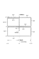
有効探索範囲対応パラメータテーブルは、例えば、図20に示す内容を有している。つまり、有効探索範囲について、[1]無制限、[2]制限有り:180°、[3]制限有り:90°の設定ごとに対応する、水平探索角αと部分探索範囲数Nの値が示されている。
そこで、制御部27は、この有効探索範囲対応パラメータテーブルから、上記ステップS101により認識した現在の有効探索範囲の設定に対応付けられている水平探索角αと部分探索範囲数Nの値を取得する。そして、ステップS203により、このステップS202にて取得した水平探索角α、及び部分探索範囲数Nを、今回の自動撮像記録における被写体探索のパラメータとして設定する。
Next, the
The valid search range correspondence parameter table has, for example, the contents shown in FIG. That is, for the effective search range, the values of the horizontal search angle α and the number of partial search ranges N corresponding to each setting of [1] unlimited, [2] limited: 180 °, and [3] limited: 90 ° are shown. Has been.
Therefore, the
図17のステップS102においては、変数nに1を代入し、ステップS103においては、変数mに1を代入する初期化処理を実行する。
変数nは、部分探索範囲の番号を示す。また、本実施形態では、一旦、被写体を検出すると、その検出した被写体について、異なる構図による撮像記録を所定回数(例えば3回程度)実行し、それから次の被写体探索を行うようにされている。変数mは、検出された被写体ごとについての撮像記録回数を示す。
In step S102 in FIG. 17, 1 is assigned to the variable n, and in step S103, an initialization process is executed to assign 1 to the variable m.
The variable n indicates the number of the partial search range. In this embodiment, once a subject is detected, imaging and recording with a different composition is executed a predetermined number of times (for example, about three times) for the detected subject, and then the next subject search is performed. The variable m indicates the number of times of imaging and recording for each detected subject.
ステップS104においては、被写体探索用に予め規定した画角となるようにズーム制御を実行する。
この被写体探索用に規定した画角をどのように設定するのかについては、いくつか考えることができるが、ここでは、最も基本的な例として、光学系部21が有する撮像レンズで得られる最も広い画角(以降、ワイド端ともいう)を設定するものとする。ワイド端とすることで、そのレンズにより得られる撮像視野角範囲は最も広くなるので、それだけ効率よく被写体を検出することが可能になる。
図18(b)は、ステップS104として、被写体探索用の画角としてワイド端を設定するための処理であり、制御部27は、ステップS301により、撮像レンズがワイド端となるようにしてズーム制御を実行する。
In step S104, zoom control is executed so that the angle of view defined in advance for subject search is obtained.
There are several ways of setting the angle of view defined for the object search, but here, as the most basic example, the widest range that can be obtained with the imaging lens of the
FIG. 18B shows processing for setting the wide end as the field angle for subject search in step S104. The
ステップS105においては、第n部分探索範囲DVnを探索するためのパン・チルト制御を開始する。つまり、第n部分探索範囲DVnにおいて、先に図12若しくは図13により説明した二次元探索パターンでパンニング・チルティングの動きが得られるようにパン・チルト制御を実行していく。 In step S105, pan / tilt control for searching for the nth partial search range DVn is started. In other words, in the nth partial search range DVn, pan / tilt control is executed so that panning / tilting motion can be obtained with the two-dimensional search pattern described above with reference to FIG.
なお、二次元探索パターンのためのパン・チルト制御としては、次のような構成を考えることができる。
1つには、例えばデジタルスチルカメラ1の制御部27(パン・チルト・ズーム制御ブロック63)が、雲台10に対して、制御部51(パン・チルト制御処理ブロック72)に対して、例えば図12の二次元探索パターンを形成する矢印Sc1〜Sc12ごとに対応して、パンニング、チルティングが行われるように、パン/チルト移動方向、パン/チルト移動量、移動速度などの指示を行う、というものである。
Note that the following configuration can be considered as pan / tilt control for a two-dimensional search pattern.
For example, for example, the control unit 27 (pan / tilt / zoom control block 63) of the digital
また、もう1つには、例えば図12の二次元探索パターンを形成する矢印Sc1〜Sc12に対応した、被写体探索用のパンニング・チルティングパターンを記憶させておく。そして、デジタルスチルカメラ1の制御部27(パン・チルト・ズーム制御ブロック63)からは、雲台10の制御部51(パン・チルト制御処理ブロック72)に対して、例えば第n部分探索範囲DVnの水平中心位置Hとなるパン位置への移動を指示し、この後、水平探索角αを指定したうえで、二次元探索パターンによる探索を一巡させることを指示する。この指示に応じて、雲台10の制御部51(パン・チルト制御処理ブロック72)が、記憶されている二次元探索パターンを呼び出して、パンニング・チルティング駆動を行う。このとき、パン方向における可動範囲については、指定された水平探索角αに対応した角度としてパンニングを実行させる。この構成であれば、デジタルスチルカメラ1のほうでは、二次元探索パターンのためのパン・チルト駆動制御のための機能を有していなくとも、例えば第n部分探索範囲DVnの探索を命令するだけで、二次元探索パターンによる探索の挙動が得られる。
In addition, for example, a panning / tilting pattern for searching for a subject corresponding to the arrows Sc1 to Sc12 forming the two-dimensional search pattern of FIG. 12 is stored. Then, from the control unit 27 (pan / tilt / zoom control block 63) of the digital
上記ステップS105により開始された第n部分探索範囲DVnでの二次元探索パターンによるパン・チルトの動きが得られている状態の下、制御部27は、ステップS106により被写体が検出されるのを待機する。
このために、制御部27は、構図判定ブロック62(信号処理部24)により、取り込んだ撮像画像データを利用して被写体検出処理を実行する。この被写体検出処理としては、例えば顔検出技術を応用し、その検出結果として、検出した被写体ごとに、その顔の画像部分の領域に対応して顔枠を設定する。例えば、被写体数であるとか、被写体検出時点での被写体サイズ及び画枠内の位置などの被写体に関する基本的情報は、この顔枠FRの数、サイズ、位置などにより得ることができる。また、顔枠FRが設定されることに応じて、この段階で、被写体ごとの重心であるとか、複数の被写体についての総合的な重心も取得される。
なお、この顔検出の方式、手法はいくつか知られているが、本実施形態においてはどの方式を採用するのかについては特に限定されるべきものではなく、検出精度や設計難易度などを考慮して適当とされる方式が採用されればよい。
The
For this purpose, the
There are several known face detection methods and methods, but in this embodiment, which method should be adopted is not particularly limited, taking into account detection accuracy, design difficulty, etc. It is only necessary to adopt an appropriate method.
そのうえで、ステップS106としては、上記の被写体検出処理によって、第n部分探索範囲DVnでの二次元探索パターンによる被写体探索が一巡するまでに、少なくとも1つの被写体が検出されるのを待機する。ここで、被写体が検出されたことが判別されれば、ステップS107以降の手順に進む。これに対して、被写体が検出されなかった場合には、ステップS112に進む。 In step S106, the process waits until at least one subject is detected by the subject detection process before the subject search by the two-dimensional search pattern in the nth partial search range DVn is completed. If it is determined that the subject has been detected, the process proceeds to step S107 and subsequent steps. On the other hand, if no subject is detected, the process proceeds to step S112.
ステップS107においては、構図判定処理と、この構図判定処理による構図判定結果に応じた構図合わせ制御を実行する。
被写体が検出された段階では、検出された被写体ごとに、被写体情報として、顔枠FRの情報(位置、サイズなど)、被写体重心及び総合被写体重心、属性として検出された年代、性別、顔方向を示す情報などが得られている。
そこでステップS107においては、制御部27(構図判定ブロック62)が上記の被写体情報を利用して最適構図を決定する、構図判定処理を実行する。
この構図判定処理により、画枠内における被写体の重心が在るべき位置であるとか、ズーム倍率(被写体サイズの拡大率)などが決定される。この構図判定処理による構図判定結果の情報は、例えばパン・チルト・ズーム制御ブロック63に対して渡される。
そこで、パン・チルト・ズーム制御ブロック63は、渡された構図判定結果に応じた撮像視野角が得られるようにするためのパン・チルト・ズーム制御を実行する。つまり、構図合わせ制御を実行する。
In step S107, composition determination processing and composition adjustment control according to the composition determination result by this composition determination processing are executed.
At the stage where a subject is detected, for each detected subject, information on the face frame FR (position, size, etc.), subject center of gravity and total subject center of gravity, subject age, gender, and face direction are detected as subject information. Information to show is obtained.
Therefore, in step S107, a composition determination process is performed in which the control unit 27 (composition determination block 62) determines the optimum composition using the subject information.
This composition determination process determines the position where the center of gravity of the subject should be in the image frame, the zoom magnification (subject size enlargement ratio), and the like. Information on the composition determination result by the composition determination processing is passed to the pan / tilt /
Therefore, the pan / tilt /
上記ステップS107による構図合わせ制御が開始されて以降においては、制御部27(構図判定ブロック62)は、ステップS108により、実際にそのときの撮像画像データの画像として得られている構図が、ステップS107により判定した構図と同じであるとみなされる状態(例えば一定以上の近似度となる状態)となったか否か(構図がOKであるか否か)を判別する。
また、本実施形態のデジタルスチルカメラ1は、検出された被写体の顔の表情として少なくとも笑顔を検出可能とされている。そのうえで、構図判定結果としては、例えば被写体が笑顔であることを指定する内容を含めることもできる。このようにして構図判定結果に、被写体が笑顔であることの指定が含められている場合には、ステップS108による構図OKか否かの判定にあたって、被写体が笑顔であるか否かについての検出結果も利用することになる。
After the composition adjustment control in step S107 is started, the control unit 27 (composition determination block 62) obtains the composition actually obtained as an image of the captured image data at that time in step S108. It is determined whether or not a state regarded as being the same as the composition determined by (for example, a state having a certain degree of approximation or more) is reached (whether or not the composition is OK).
In addition, the digital
ここで、例えば構図合わせとして必要なだけの移動量によるパン・チルト・ズーム駆動を行わせた状態で一定時間を待機しても構図がOKにならなかった場合には、ステップS108にて否定の判別結果が得られる。この場合には、ステップS112に進む。
これに対して、ステップS108にて構図がOKになったとの判別結果が得られた場合には、ステップS109に進む。
Here, for example, if the composition does not become OK even after waiting for a fixed time in a state where pan / tilt / zoom driving is performed with a movement amount necessary for composition adjustment, a negative result is obtained in step S108. A discrimination result is obtained. In this case, the process proceeds to step S112.
On the other hand, if it is determined in step S108 that the composition is OK, the process proceeds to step S109.
ステップS109においては、例えば制御部27は、撮像記録ブロック61に対して撮像記録を指示する。これに応じて、そのときに得られている撮像画像データを、メモリカード40に対して静止画のファイルとして記録する動作が実行される。このステップS109の処理が、最後のステップS106にて被写体が検出されたことに応じて最初に実行されたものである場合、先ず、検出された被写体について1枚目の撮像画像データが記録されたことになる。
In step S109, for example, the
制御部27は、ステップS110により変数mについてインクリメントしたうえで、ステップS111にて変数mが最大値よりも大きいか否かについて判別する。ここで変数mと比較される最大値は、一度検出された被写体について構図を変更して撮像記録すべき回数に対応する。例えば撮像記録すべき回数が3回であるとされていれば、ここでの最大値は3となる。
ステップS111にて変数mが最大値以下であるとして、否定の判別結果が得られた場合には、未だ、検出した被写体についての規定回数分の撮像記録を行っていないことになる。そこで、この場合には、ステップS107に戻り、次の撮像記録のための構図判定処理、構図合わせ制御を実行する。なお、このときの構図判定処理は、前回の構図判定処理とは異なる構図を設定するための処理となる。例えば、構図としての被写体の顔の向きを、前回とは異なるものとして設定することが考えられる。また、画枠内における被写体の位置、サイズなどを変更して設定することが考えられる。また、前回は笑顔でなくても良かったが、今回は被写体の顔が笑顔であるべきことを条件にすることが考えられる。
このようにして検出された被写体ごとに、規定回数分の撮像記録を行えば、同じ被写体で異なる構図による複数の撮像画像を記録できる。
The
If a negative determination result is obtained assuming that the variable m is equal to or less than the maximum value in step S111, the imaging and recording of the detected subject for the specified number of times has not been performed yet. Therefore, in this case, the process returns to step S107, and composition determination processing and composition adjustment control for the next imaging / recording are executed. The composition determination process at this time is a process for setting a composition different from the previous composition determination process. For example, it is conceivable to set the direction of the subject's face as a composition different from the previous one. It is also conceivable to change and set the position and size of the subject within the image frame. Although it was not necessary to have a smile last time, it is conceivable that the subject's face should be a smile this time.
If a predetermined number of times of imaging and recording are performed for each subject detected in this way, a plurality of captured images with different compositions can be recorded on the same subject.
上記のようにして、一度検出された被写体については、規定回数分の撮像記録が行われる。そして、この規定回数分の撮像記録を終了すると、ステップS111において肯定の判別結果が得られ、ステップS112に進む。 As described above, a predetermined number of times of imaging and recording are performed on the subject once detected. When the predetermined number of times of imaging and recording are completed, a positive determination result is obtained in step S111, and the process proceeds to step S112.
ステップS112に至る場合としては、次のようになる。1つは、第n部分探索範囲DVnでの二次元探索パターンによる被写体探索を一巡させても被写体が検出されず、ステップS106にて否定の判別結果が得られた場合となる。また、もう1つは、被写体が検出されて構図合わせ制御を実行したとしても構図がOKにならず、ステップS108にて否定の判別結果が得られた場合となる。さらに、検出した被写体について規定回数分の撮像記録が完了してステップS111にて肯定の判別結果が得られた場合となる。
これらの場合は、いずれについても、第n部分探索範囲DVnに対する探索を終了して、次の部分探索範囲に移行してよい状況である。
The case of reaching step S112 is as follows. One is a case where the subject is not detected even if the subject search by the two-dimensional search pattern in the nth partial search range DVn is completed and a negative determination result is obtained in step S106. The other is a case where the composition is not OK even if the subject is detected and the composition adjustment control is executed, and a negative determination result is obtained in step S108. Further, this is a case in which the predetermined number of times of imaging and recording has been completed for the detected subject and a positive determination result is obtained in step S111.
In any of these cases, the search for the nth partial search range DVn may be terminated and the next partial search range may be entered.
そこで、制御部27は、ステップS112において変数nについてインクリメントしたうえで、ステップS113により変数nが部分探索範囲数Nより大きいか否かについて判別する。
ステップS113にて変数nが部分探索範囲数N以下であるとして否定の判別結果が得られた場合には、未だ、全ての部分探索範囲ごとの二次元探索パターンによる被写体探索が一巡していないことになる。そこで、この場合には、ステップS103に戻る。これにより、次の番号の部分探索範囲についての二次元探索パターンによる被写体探索が開始されることになる。また、再度、ステップS104の処理を経ることで、その前の構図合わせ制御によってズーミングなどが行われていたとしても、再度、探索用の画角(例えばこの場合にはテレ端)となるようにして再設定される。
Therefore, the
If a negative determination result is obtained in step S113 that the variable n is equal to or less than the number N of partial search ranges, the subject search using the two-dimensional search pattern for each partial search range has not been completed yet. become. In this case, the process returns to step S103. Thereby, the subject search by the two-dimensional search pattern for the partial search range of the next number is started. Further, through the process of step S104 again, even if zooming or the like has been performed by the previous composition adjustment control, the angle of view for search (for example, the tele end in this case) is set again. Will be reset.
そして、ステップS113からステップS103に戻っての処理を繰り返していく結果、或る段階で、全ての部分探索範囲ごとの二次元探索パターンによる被写体探索が一巡した段階で、ステップS113により肯定の判別結果が得られることになる。この場合には、ステップS102に戻る。これにより、第1部分探索範囲DV1からの二次元探索パターンによる被写体探索が、再度開始されることになる。 Then, as a result of repeating the processing from step S113 to step S103, the result of affirmative determination is made in step S113 at a stage where the subject search by the two-dimensional search pattern for every partial search range is completed in a certain stage. Will be obtained. In this case, the process returns to step S102. Thereby, the subject search by the two-dimensional search pattern from the first partial search range DV1 is started again.
[5−1−1.パラメータ設定の変形例]
ここで、図17のステップS101としてのパラメータ(水平探索角α、部分探索範囲数N)設定の変形例を挙げておく。
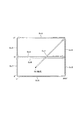
先ず、有効対応範囲パラメータテーブルについては、図20に代えて、図21に示す内容を有しているものとする。
図21に示す有効対応範囲パラメータテーブルにおいては、光学系部21のレンズのワイド端での画角値(ワイド端画角値)γについて所定値以上の場合と所定値未満の場合とのそれぞれについて、有効探索範囲の設定ごとに応じた水平探索角α及び部分探索範囲数Nとの対応が示されている。
なお、ここでの画角値γは、焦点距離により表すものとする。また、あくまでも一例であるが、ここでは、レンズのワイド端画角値γについて、25mm(焦点距離:35mm換算)以上と25mm未満とで区分している。
[5-1-1. Modified example of parameter setting]
Here, a modified example of setting parameters (horizontal search angle α, number of partial search ranges N) as step S101 in FIG. 17 will be given.
First, it is assumed that the effective correspondence range parameter table has the contents shown in FIG. 21 instead of FIG.
In the effective correspondence range parameter table shown in FIG. 21, the field angle value (wide end field angle value) γ at the wide end of the lens of the
Here, the angle of view value γ is represented by a focal length. Also, as an example to the last, here, the wide end field angle value γ of the lens is divided into 25 mm (focal length: 35 mm equivalent) or more and less than 25 mm.
そして、図21の有効対応範囲パラメータテーブルは、ワイド端画角値γが25mm以上の場合については、図20と同様の内容とされている。
これに対して、ワイド端画角値γが25mm未満では、有効対応範囲が無制限の場合には、水平探索角α=120°で部分探索範囲数N=3、有効対応範囲が制限有りで180°の場合には、水平探索角α=90°で部分探索範囲数N=2、有効対応範囲が制限有りで90°の場合には、水平探索角α=90°で部分探索範囲数N=1となっている。これをワイド端画角値γが25mm以上の場合と比較すると、有効対応範囲が無制限の場合と、有効対応範囲が制限有りで180°の場合とで、水平探索角αは拡大された設定となっている。これに応じて、部分探索範囲数Nについては少なくなっている。
The effective correspondence range parameter table in FIG. 21 has the same contents as those in FIG. 20 when the wide-end field angle value γ is 25 mm or more.
On the other hand, when the wide end angle of view value γ is less than 25 mm and the effective corresponding range is unlimited, the horizontal search angle α = 120 °, the number of partial search ranges N = 3, and the effective corresponding range is limited. In the case of °, the horizontal search angle α = 90 ° and the number of partial search ranges N = 2, and in the case where the effective correspondence range is limited and 90 °, the horizontal search angle α = 90 ° and the number of partial search ranges N = 1 Compared with the case where the wide-end angle of view value γ is 25 mm or more, the horizontal search angle α is set to an expanded setting when the effective support range is unlimited and when the effective support range is limited and 180 °. It has become. Accordingly, the number N of partial search ranges is reduced.
このようにして、レンズのワイド端画角値に応じて、1つの有効探索範囲に対応する部分探索範囲数N及び水平探索角αを変更するようにしているのは、次のような理由による。
現状、デジタルスチルカメラのレンズについては、より広画角のものが採用される傾向になってきている。デジタルスチルカメラ1のレンズが相当に広角になるほど、定位置にあって被写体探索できる範囲も広がることになる。このことを考慮すると、レンズが一定以上に広角であるような場合にも、例えば35mm程度のテレ端を前提としたデフォルトの部分探索範囲数N及び水平探索角αでは、部分探索範囲ごとに重複して探索される領域が多すぎることになって、被写体探索としてはあまり効率が良くなくなる場合もあると考えられる。
そこで、変形例としては、ワイド端画角値γが一定以上のレンズの場合に対応しては、通常よりも、水平探索角αを広く取り、これに応じて部分探索範囲DVの数も削減することとしたものである。なお、図21の例では、有効探索範囲が90°で制限されている場合には、ワイド端画角値γに関わらず、水平探索角α=90°、部分探索範囲数N=1としている。これは、例えば、既に有効探索範囲について90°という比較的狭い範囲に制限されている状況にあって、ここからさらに水平探索角αを拡大することは特に意味がない、という理由による。
In this way, the number of partial search ranges N and the horizontal search angle α corresponding to one effective search range are changed according to the wide-angle field angle value of the lens for the following reason. .
At present, with regard to the lens of the digital still camera, a lens having a wider angle of view is being adopted. The wider the angle of the lens of the digital
Therefore, as a modified example, the horizontal search angle α is set wider than usual and the number of partial search ranges DV is also reduced correspondingly in the case of a lens having a wide end angle of view value γ of a certain value or more. It was decided to do. In the example of FIG. 21, when the effective search range is limited to 90 °, the horizontal search angle α = 90 ° and the number of partial search ranges N = 1 regardless of the wide end angle of view value γ. . This is because, for example, the effective search range is already limited to a relatively narrow range of 90 °, and it is not particularly meaningful to further increase the horizontal search angle α from here.
図19のフローチャートは、この変形例としてのパラメータ設定に対応した、図17のステップS101としての処理手順例を示している。
図19のステップS401において、制御部27は、図18(a)のステップS201と同様に、有効探索範囲設定情報を参照して、現在の有効探索範囲についての設定内容を認識する。
次に、制御部27は、ステップS402により、光学系部21が有するレンズのワイド端画角値γを取得する。レンズのワイド端画角値γの値の情報は、例えば、レンズがデジタルスチルカメラ1に組み込みとされている構造であれば、フラッシュメモリ30やROM28などに保持されている。また、レンズが交換可能である場合には、交換レンズが自身のワイド端画角値のデータを保持している。そこで、この場合には、デジタルスチルカメラ1の制御部27が交換レンズ側のCPUなどと通信を行うことで、ワイド端画角値γを取得することができる。
The flowchart in FIG. 19 shows an example of a processing procedure as step S101 in FIG. 17 corresponding to the parameter setting as this modification.
In step S401 in FIG. 19, the
Next, in step S402, the
ステップS403において制御部27は、図21に示す有効探索範囲対応範囲パラメータテーブルを参照する。そして、ステップS402にて取得したワイド端画角値γと、ステップS401にて認識した有効探索範囲の設定とに対応付けられている水平探索角α及び部分探索範囲数Nを取得する。
一例であるが、ステップS402にて取得したワイド端画角値γ=24mmで、かつ、ステップS401にて認識した有効探索範囲の設定が、180°で制限されているものとした場合、これに対応するものとして、ステップS403では、水平探索角α=90°、部分探索範囲数N=2が取得されることになる。
そしてステップS404において、上記ステップS403にて取得した水平探索角α=90°、部分探索範囲数N=2を、今回の自動撮像記録における被写体探索のパラメータとして設定する。
In step S403, the
As an example, when the wide end angle of view value γ = 24 mm acquired in step S402 and the setting of the effective search range recognized in step S401 is limited to 180 °, Correspondingly, in step S403, the horizontal search angle α = 90 ° and the partial search range number N = 2 are acquired.
In step S404, the horizontal search angle α = 90 ° and the number of partial search ranges N = 2 acquired in step S403 are set as parameters for subject search in the current automatic imaging recording.
<6.被写体探索挙動例4:部分探索範囲設定(第2例)>
これまで説明した第1例の部分探索範囲設定としては、360°、180°、90°のパン方向における回転角度を、同じ水平探索角αによる第1部分探索範囲DV1〜第n部分探索範囲DVnで等分割して設定している。この場合、パン方向における角度範囲が他の部分探索範囲とは重複しないようにされている。そして、1つの部分探索範囲での探索を完了すると、次の部分探索範囲に移動して、パン方向における角度範囲が他の部分探索範囲とは重複しないようにされている。
<6. Subject Search Behavior Example 4: Partial Search Range Setting (Second Example)>
As the partial search range setting of the first example described so far, the rotation angles in the pan direction of 360 °, 180 °, and 90 ° are set to the first partial search range DV1 to the nth partial search range DVn with the same horizontal search angle α. Are set in equal divisions. In this case, the angle range in the pan direction does not overlap with other partial search ranges. When the search in one partial search range is completed, the search moves to the next partial search range so that the angle range in the pan direction does not overlap with the other partial search ranges.
これに対して、第2例としては、次に説明するようにして部分探索範囲設定を設定する。
図22は、第2例の部分探索範囲の設定の仕方と、これに応じた、被写体探索の挙動例を示している。なお、図22に示されるデジタルスチルカメラ1は、雲台10に載置されているのであるが、ここでは図を簡略で見やすいものとすることの都合上、雲台10は省略している。
On the other hand, as a second example, the partial search range setting is set as described below.
FIG. 22 shows how to set the partial search range of the second example and an example of subject search behavior corresponding to this. Although the digital
ここで、デジタルスチルカメラ1は、雲台10により、図22(a)に示される部分探索範囲DVにて、図12又は図13の二次元探索パターンによる被写体探索を実行しているものとする。ここでは、例として、部分探索範囲DVの水平探索角α=90°としている。
Here, it is assumed that the digital
そして、図22(a)に示す部分探索範囲DVにて被写体探索を行っている過程で、図22(b)に示される位置にデジタルスチルカメラ1の撮像方向F1が向いた状態において、被写体HSが検出されたとする。そして、この被写体について、撮像記録を完了させたとする。
Then, in the process of searching for a subject in the partial search range DV shown in FIG. 22A, the subject HS in the state where the imaging direction F1 of the digital
ここで、図22(b)において被写体を検出したときの撮像方向F1に対応するパン位置をP1とする。そして、次の探索対象となる部分探索範囲は、図22(c)に示すようにして、パン位置P1を水平中心位置H(0°)とする+45°〜−45°の範囲として設定する。 Here, in FIG. 22B, the pan position corresponding to the imaging direction F1 when the subject is detected is defined as P1. Then, as shown in FIG. 22C, the partial search range to be the next search target is set as a range of + 45 ° to −45 ° with the pan position P1 as the horizontal center position H (0 °). .
また、図23に、第2例としての部分探索範囲設定についての他の例を示す。
ここで、図23(a)から図23(b)までの動作の遷移は、上記図22(a)(b)と同じとしている。
そのうえで、この他の例では、図23(c)に示すように、図23(b)において被写体を検出したときの撮像方向F1に対応するパン位置P1からパン方向において90°回転させたときのパン位置を、新たな水平中心位置H(0°)とする。そして、この新たな水平中心位置H(0°)をパン方向の中心とする+45°〜−45°の90°の範囲を、次の部分探索範囲DVとして設定することになる。
つまり、図22の動作が、被写体が検出されたパン位置を新たな部分探索範囲DVの水平中心位置Hとするのに対して、図23の動作では、被写体が検出されたパン位置から予め設定した所定角度だけパン方向に回転させたパン位置を、新たな部分探索範囲DVの水平中心位置Hとする。
FIG. 23 shows another example of the partial search range setting as the second example.
Here, the transition of the operation from FIG. 23A to FIG. 23B is the same as that in FIG. 22A and FIG.
In addition, in this other example, as shown in FIG. 23 (c), when the subject is detected in FIG. 23 (b), it is rotated 90 ° in the pan direction from the pan position P1 corresponding to the imaging direction F1. The pan position is set as a new horizontal center position H (0 °). Then, a range of 90 ° from + 45 ° to −45 ° with the new horizontal center position H (0 °) as the center in the pan direction is set as the next partial search range DV.
That is, while the operation of FIG. 22 sets the pan position where the subject is detected as the horizontal center position H of the new partial search range DV, the operation of FIG. 23 sets in advance from the pan position where the subject is detected. The pan position rotated in the pan direction by the predetermined angle is set as the horizontal center position H of the new partial search range DV.
このように、上記図22,23に示した第2例のパン方向の回転動作では、予め分割区分された部分探索範囲DVを移動していくのではなく、被写体が検出されたときの撮像方向F1に基づいて新たな水平中心位置H(0°)を決めることで、新たな部分探索範囲DVを設定する。そして、この新たに設定された新たな部分探索範囲DVにより被写体探索を行う、という動作を繰り返していく。
このような探索の仕方とすることで、より丹念に探索が行われることとなり、例えば相当に被写体となる人数が多いなどの周囲の状況などによっては、第1例などよりも好ましい画内容の撮像画像データを自動記録できる。
As described above, in the rotation operation in the pan direction of the second example shown in FIGS. 22 and 23, the imaging direction when the subject is detected is not moved in the partial search range DV divided in advance. A new partial search range DV is set by determining a new horizontal center position H (0 °) based on F1. Then, the operation of searching for a subject using the newly set new partial search range DV is repeated.
By using such a search method, the search is performed more carefully. For example, depending on the surrounding situation such as a large number of subjects as subjects, imaging of image contents that is more preferable than the first example is performed. Image data can be recorded automatically.
なお、この第2例においても、被写体探索を開始してから被写体検出されるまでは、第1例の図14,図15などの場合と同様に、第1部分探索範囲DV1〜第n部分探索範囲DVnにより等分割したうえで、これらの部分探索範囲を順次移動しながら、二次元探索パターンによる被写体探索を巡回させていくようにしている。そして、被写体が検出されると、以降は、上記図22、図23に示した部分探索範囲により被写体探索を実行する。また、例えば、上記図22、図23に示した部分探索範囲設定による被写体探索に移行した後において被写体が検出されなくなれば、再び、等分割した第1部分探索範囲DV1〜第n部分探索範囲DVnごとに被写体探索を実行する第1例の動作に戻す。 Also in the second example, from the start of the subject search until the subject is detected, the first partial search range DV1 to the nth partial search is performed as in the case of the first example shown in FIGS. After equally dividing the range DVn, the subject search by the two-dimensional search pattern is circulated while sequentially moving these partial search ranges. When the subject is detected, the subject search is subsequently performed within the partial search range shown in FIGS. Further, for example, if the subject is not detected after the shift to the subject search by the partial search range setting shown in FIGS. 22 and 23, the first partial search range DV1 to the nth partial search range DVn which are equally divided again. The operation returns to the first example in which the subject search is executed every time.
ところで、この第2例としての動作は、有効探索範囲が無制限である場合には、時計回り方向若しくは反時計回り方向に従って、図22の動作を巡回させていけばよい。
これに対して、図15,図16などのように有効探索範囲について360°未満の制限が与えられる場合には、部分探索範囲DVが有効探索範囲の限界位置にまできた場合において、どのようにし反対側のパン方向に折り返させるべきかを考慮する必要が出てくる。
By the way, in the operation as the second example, when the effective search range is unlimited, the operation of FIG. 22 may be circulated in the clockwise direction or the counterclockwise direction.
On the other hand, when the limit of less than 360 ° is given to the effective search range as shown in FIGS. 15 and 16, how is the partial search range DV reached when reaching the limit position of the effective search range? It will be necessary to consider whether it should be folded in the opposite pan direction.
そこで、図24、図25により、有効探索範囲が制限されている場合の回転動作例について説明する。ここでは、制限された有効探索範囲VLの角度は180°であり、部分探索範囲DVとしての水平探索角α=60°を設定していることを前提とする。
また、ここでは、180°の有効探索範囲VLについて、その中心を0°とし、時計回り方向の限界位置を+90°、反時計回り方向の限界位置を−90°としている。
また、この図においては雲台10及びデジタルスチルカメラ1の図示は省略して、その探索動作を模式的に示したものとなっている。ここでは、デジタルスチルカメラ1本体の回転軸11aを示している。
Accordingly, an example of the rotation operation when the effective search range is limited will be described with reference to FIGS. 24 and 25. Here, the angle of the limited effective search range VL is 180 °, and it is assumed that the horizontal search angle α = 60 ° is set as the partial search range DV.
Further, here, regarding the effective search range VL of 180 °, the center is set to 0 °, the limit position in the clockwise direction is set to + 90 °, and the limit position in the counterclockwise direction is set to −90 °.
Further, in this figure, illustration of the
ここでは、先ず、180°の有効探索範囲VLを探索している過程において、図24(a)に示すようにして、−75°のパン位置に撮像方向F1が向いたときに被写体HSが検出され、自動撮像記録が完了したとする。 Here, first, in the process of searching for the effective search range VL of 180 °, the subject HS is detected when the imaging direction F1 is directed to the pan position of −75 ° as shown in FIG. Suppose that automatic imaging recording is completed.
この場合、水平探索角αについては60°としている。従って、第2例としては、図24(a)の撮像方向F1が対応するパン位置を水平中心位置Hとして設定することになる。すると、この際に設定される部分探索範囲DVとしては、図24(b)に示すようにして、水平中心位置H(−75°)から-45°までの時計回り方向の30°の探索角(+2/α)については確保できる。しかし、反時計回り方向については、水平中心位置H(−75°)から-90°までの15°の探索角しか確保できない。
しかし、この場合の動作例では、この-45°〜H(−75°)〜-90°の範囲を部分探索範囲DVとして設定し、図12、図13に示した実施形態の二次元探索パターンによる被写体探索を実行させる。
この場合、水平中心位置H(−75°)から時計回り方向へのパンニングは30°で行うが、水平中心位置H(−75°)から反時計回り方向へのパンニングは、15°により行うこととなる。従って、この場合の二次元探索パターンは、図12、図13のように左右対称となるのではなく、非対称となる。
In this case, the horizontal search angle α is set to 60 °. Therefore, as a second example, the pan position corresponding to the imaging direction F1 in FIG. Then, as the partial search range DV set at this time, as shown in FIG. 24 (b), a search angle of 30 ° in the clockwise direction from the horizontal center position H (−75 °) to −45 °. (+ 2 / α) can be secured. However, in the counterclockwise direction, only a search angle of 15 ° from the horizontal center position H (−75 °) to −90 ° can be secured.
However, in the operation example in this case, this range of −45 ° to H (−75 °) to −90 ° is set as the partial search range DV, and the two-dimensional search pattern of the embodiment shown in FIGS. Subject search is executed.
In this case, panning in the clockwise direction from the horizontal center position H (−75 °) is performed at 30 °, but panning in the counterclockwise direction from the horizontal center position H (−75 °) is performed at 15 °. It becomes. Therefore, the two-dimensional search pattern in this case is not symmetrical as shown in FIGS. 12 and 13, but is asymmetric.
次に、例えば上記図24(b)に示した部分探索範囲DVでの探索によっては、被写体が検出されなかったとする。この場合、これ以上、反時計回り方向に対して探索を行っていくことはできない。そこで、何らかの規則に従って、時計回り方向に移動して部分探索範囲DVを設定する必要がある。
そこで、この場合には、図25(a)に示すようにして新たな部分探索範囲DVを設定する。つまり、図24(b)にて設定されていた部分探索範囲DVの水平中心位置をH'とすると、この水平中心位置H'が位置するパン位置から時計回り方向に120°回転したパン位置+45°が新たな部分探索範囲DVの水平中心位置Hとなるようにしてパンニングを行う。これにより、部分探索範囲DVは、0°を対称に、反対側の角度範囲に位置させることができる。そして、この新たな部分探索範囲DVにて被写体探索を実行する。
Next, for example, it is assumed that the subject is not detected by the search in the partial search range DV shown in FIG. In this case, no further search can be performed in the counterclockwise direction. Therefore, it is necessary to set the partial search range DV by moving clockwise according to some rule.
Therefore, in this case, a new partial search range DV is set as shown in FIG. That is, assuming that the horizontal center position of the partial search range DV set in FIG. 24B is H ′, the pan position rotated clockwise by 120 ° from the pan position where the horizontal center position H ′ is located + Panning is performed so that 45 ° is the horizontal center position H of the new partial search range DV. As a result, the partial search range DV can be positioned in the opposite angular range with 0 ° symmetrically. Then, the subject search is executed in the new partial search range DV.
なお、ここでの部分探索範囲DVの移動のための反転方向への回転角度としては、120°を設定しているが、これは、有効探索範囲が180°で、部分探索範囲DVの水平探索角α=60°とした場合において、移動後の部分探索範囲DVがおおむねパン位置となることを考慮して設定した値の一具体例である。 The rotation angle in the reverse direction for moving the partial search range DV here is set to 120 °, but this is a horizontal search of the partial search range DV with an effective search range of 180 °. This is a specific example of a value set in consideration of the fact that the partial search range DV after movement is generally the pan position when the angle α is 60 °.
また、この図25(a)にて設定された部分探索範囲DVにて被写体探索を行った結果、被写体が検出されなかったとする。すると、この場合には、図25(b)に示すようにして、図25(a)にて設定されていた部分探索範囲DVの水平中心位置をH'として、この水平中心位置H'が位置するパン位置から反時計回り方向に60°回転したパン位置-15°が新たな水平中心位置Hとなるようにしてパン移動させる。これにより、次の部分探索範囲DVとしては、0°近傍のほぼ正面付近にあるようにできる。そして、このパン位置-15°に対して±30°の範囲(+15°〜-15°〜-45°)を部分探索範囲DVとして被写体探索を実行する。
なお、ここでまでの動作過程によると、パン位置+90°〜+75°の範囲は探索されないことになる。しかし、このパン位置+90°〜+75°にまでパンニングしなくとも、レンズの画角によって、パン位置+90°〜+75°にて得られるとされる必要な撮像視野角範囲が得られている。従って、この場合においてパン位置+90°〜+75°の範囲を探索しなくとも、特に問題にはならない。
Further, it is assumed that the subject is not detected as a result of the subject search in the partial search range DV set in FIG. Then, in this case, as shown in FIG. 25 (b), the horizontal center position H ′ of the partial search range DV set in FIG. The pan is moved so that the pan position -15 ° rotated 60 ° counterclockwise from the pan position to be rotated becomes the new horizontal center position H. As a result, the next partial search range DV can be approximately near the front near 0 °. The subject search is executed with the range of ± 30 ° (+ 15 ° to -15 ° to -45 °) with respect to the pan position of -15 ° as the partial search range DV.
In addition, according to the operation process up to here, the range of the pan position + 90 ° to + 75 ° is not searched. However, even if the pan position is not panned to + 90 ° to + 75 °, the required viewing angle range obtained at the pan position + 90 ° to + 75 ° can be obtained depending on the angle of view of the lens. ing. Therefore, in this case, there is no particular problem even if the range of the pan position + 90 ° to + 75 ° is not searched.
また、この図25(b)の部分探索範囲DVでの探索によっても被写体が検出されなかった場合には、例えば、撮像方向F1を0°に戻して一旦停止した後、被写体が検出されるまでは、例えば図15などにて説明した分割された部分探索範囲ごとの被写体探索を順次実行する。 If the subject is not detected by the search in the partial search range DV in FIG. 25B, for example, the imaging direction F1 is returned to 0 ° and stopped, and then the subject is detected. For example, the subject search for each of the divided partial search ranges described in FIG.
なお、これまでの実施形態の説明では、図14以降において説明した、部分探索範囲ごとの探索動作としては、図12,若しくは図13に示した二次元探索パターンにより行うものとして説明した。しかし、探索動作としての観点からは、例えば、単純に或る所定のパン位置が設定された状態で、単純にパン方向に移動する、という部分探索範囲における探索動作としても、例えば360°にわたってパン方向に移動するような探索動作と比較すれば、探索効率は向上されるといえる。 In the description of the embodiments so far, the search operation for each partial search range described in FIG. 14 and after has been described as being performed by the two-dimensional search pattern shown in FIG. However, from the viewpoint of the search operation, for example, the search operation in the partial search range of simply moving in the pan direction in a state where a certain predetermined pan position is set is, for example, panning over 360 °. Compared with a search operation that moves in a direction, it can be said that the search efficiency is improved.
また、これまでの実施形態の説明では、フローチャートとして各図に示した処理手順は、デジタルスチルカメラ1の制御部27がプログラムに従って実行するものであるとしている。
しかし、例えばフローチャートとして各図に示した処理手順の少なくとも1つが雲台10側において実行されるようにして構成してもよい。ただし、主立った被写体探索、構図判定、及び自動撮像記録のための制御機能を、デジタルスチルカメラ1側に設けることで、多様な機種のデジタルスチルカメラ1と雲台10とを組み合わせることが可能になって、汎用性という点では有利である。
また、本実施形態の撮像システムとしては、必ずしも、デジタルスチルカメラ1と雲台10とが独立した装置である必要はなく、撮像装置と雲台とが一体化された構成でもよい。但し、実施の形態のようにしてデジタルスチルカメラ1と雲台10とをそれぞれ独立した装置として構成すれば、デジタルスチルカメラ1を通常にカメラとして使用できる。
Further, in the description of the embodiments so far, it is assumed that the processing procedure illustrated in each drawing as a flowchart is executed by the
However, for example, at least one of the processing procedures shown in each drawing as a flowchart may be executed on the
In the imaging system of the present embodiment, the digital
また、これまでの説明では、自動撮像記録される画像については静止画像であるとしているが、撮像により得られた画像から生成した動画とされてもよいものである。 In the description so far, the image that is automatically captured and recorded is a still image, but may be a moving image generated from an image obtained by imaging.
また、これまでにも述べてきたように、本願に基づく構成における少なくとも一部は、CPUやDSPにプログラムを実行させることで実現できる。
このようなプログラムは、例えばROMなどに対して製造時などに書き込んで記憶させるほか、リムーバブルの記憶媒体に記憶させておいたうえで、この記憶媒体からインストール(アップデートも含む)させるようにしてDSP対応の不揮発性の記憶領域やフラッシュメモリ30などに記憶させることが考えられる。また、USBやIEEE1394などのデータインターフェース経由により、他のホストとなる機器からの制御によってプログラムのインストールを行えるようにすることも考えられる。さらに、ネットワーク上のサーバなどにおける記憶装置に記憶させておいたうえで、デジタルスチルカメラ1にネットワーク機能を持たせることとし、サーバからダウンロードして取得できるように構成することも考えられる。
As described above, at least a part of the configuration based on the present application can be realized by causing a CPU or a DSP to execute a program.
Such a program is written and stored in a ROM or the like at the time of manufacture, for example, and is stored in a removable storage medium and then installed (including update) from this storage medium. It is conceivable to store the data in a corresponding non-volatile storage area, the
1 デジタルスチルカメラ、2 本体部、21a レンズ部、31a レリーズボタン、10 雲台、11 本体部、12 カメラ台座部、13 突起部、14 コネクタ、21 光学系、22 イメージセンサ、23 A/Dコンバータ、24 信号処理部、25 エンコード/デコード部、26 メディアコントローラ、27 制御部、28 ROM、29 RAM、30 フラッシュメモリ、31 操作部、32 表示ドライバ、33 表示部、34 雲台対応通信部、40 メモリカード、51 制御部、52 通信部、53 パン機構部、54 パン用モータ、55 パン用駆動部、56 チルト機構部、57 チルト用モータ、58 チルト用駆動部、61・75 撮像記録ブロック、62・73 画構造判定ブロック、63 パン・チルト・ズーム制御ブロック、64・71 通信制御処理ブロック、72 パン・チルト制御処理ブロック
DESCRIPTION OF
Claims (8)
第1の上記部分探索範囲において上記単位パン動作を行った後は、この第1の上記部分探索範囲とは異なる第2の上記部分探索範囲において上記単位パン動作が行われるように、上記部分探索範囲を設定する、部分探索範囲設定手段と、
を備える可動機構部制御装置。 A series of operations for searching the entire partial search range set as a part of the preset movable angle range in the pan direction for the movable mechanism unit configured to move so that the imaging direction of the imaging unit changes in the pan direction. Drive control means for controlling so as to obtain a unit pan operation,
After making the unit pan operation in the first of the partial search range, so the unit pan operation is performed in the second of the partial search range different from the first the partial search range, the partial search A partial search range setting means for setting a range ;
A movable mechanism control device.
上記変更設定手段により設定された有効可動角度範囲に応じて、上記パン方向の可動角度範囲の角度値を変更設定する有効可動角度範囲対応角度値設定手段とをさらに備える、
請求項1に記載の可動機構部制御装置。 Change setting means for changing and setting the angle value of the effective movable angle range in the pan direction larger than the movable angle range in the pan direction;
An effective movable angle range corresponding angle value setting means for changing and setting the angle value of the movable angle range in the pan direction according to the effective movable angle range set by the change setting means;
The movable mechanism control device according to claim 1.
上記第2の部分探索範囲として、上記第1の部分探索範囲と重複しない角度範囲を設定する、
請求項1又は請求項2に記載の可動機構部制御装置。 The partial search range setting means includes:
An angular range that does not overlap with the first partial search range is set as the second partial search range .
The movable mechanism control device according to claim 1 or 2.
上記第1の部分探索範囲での上記単位パン動作中において、撮像部により撮像して得られる撮像画像から被写体が検出されたときには、このときのパン方向における角度位置を水平方向における中心位置とした上記第2の部分探索範囲を設定する、
請求項1乃至請求項3の何れかに記載の可動機構部制御装置。 The partial search range setting means includes:
During the unit pan operation in the first partial search range , when a subject is detected from a captured image obtained by imaging by the imaging unit, the angular position in the pan direction at this time is set as the center position in the horizontal direction. Setting the second partial search range ;
The movable mechanism part control apparatus in any one of Claims 1 thru | or 3.
請求項1乃至請求項4の何れかに記載の可動機構部制御装置。 Further comprising a lens angle-of-view corresponding angle value setting means for changing and setting the angle value of the movable angle range in the pan direction according to the angle of view of the lens included in the imaging unit.
The movable mechanism part control apparatus in any one of Claims 1 thru | or 4.
請求項1乃至請求項5の何れかに記載の可動機構部制御装置。 In the unit pan operation, the image capturing unit further includes third field angle control means for controlling to have the widest field angle in a field angle range that can be set in the lens of the imaging unit.
The movable mechanism control device according to any one of claims 1 to 5.
第1の上記部分探索範囲において上記単位パン動作を行った後は、この第1の上記部分探索範囲とは異なる第2の上記部分探索範囲において上記単位パン動作が行われるように、上記部分探索範囲を設定する、部分探索範囲設定手順と、
を実行する可動機構部制御手法。 A series of operations for searching the entire partial search range set as a part of the preset movable angle range in the pan direction for the movable mechanism unit configured to move so that the imaging direction of the imaging unit changes in the pan direction. a drive control step of controlling to units panning operation is obtained is,
After making the unit pan operation in the first of the partial search range, so the unit pan operation is performed in the second of the partial search range different from the first the partial search range, the partial search setting the range, the partial search range setting procedure,
The movable mechanism control method to execute.
撮像部の撮像方向がパン方向に変化するように動く構造の可動機構部について、予め設定されたパン方向の可動角度範囲の一部として設定される部分探索範囲内の全体を探索する一連の動作である単位パン動作が得られるように制御する駆動制御手順と、
第1の上記部分探索範囲において上記単位パン動作を行った後は、この第1の上記部分探索範囲とは異なる第2の上記部分探索範囲において上記単位パン動作が行われるように、上記部分探索範囲を設定する、部分探索範囲設定手順と、
を実行させるためのプログラム。 In the movable mechanism control device,
A series of operations for searching the entire partial search range set as a part of the preset movable angle range in the pan direction for the movable mechanism unit configured to move so that the imaging direction of the imaging unit changes in the pan direction. a drive control step of controlling to units panning operation is obtained is,
After making the unit pan operation in the first of the partial search range, so the unit pan operation is performed in the second of the partial search range different from the first the partial search range, the partial search setting the range, the partial search range setting procedure,
A program for running
Priority Applications (6)
| Application Number | Priority Date | Filing Date | Title |
|---|---|---|---|
| JP2009149874A JP5453953B2 (en) | 2009-06-24 | 2009-06-24 | Movable mechanism control device, movable mechanism control method, program |
| US12/800,504 US20100328467A1 (en) | 2009-06-24 | 2010-05-17 | Movable-mechanical-section controlling device, method of controlling movable mechanical section, and program |
| TW099117599A TW201112743A (en) | 2009-06-24 | 2010-06-01 | Movable-mechanical-section controlling device, method of controlling movable mechanical section, and program |
| EP10166199A EP2267998B1 (en) | 2009-06-24 | 2010-06-16 | Movable mechanical section controlling device, method of controlling movable mechanical section, and program |
| KR1020100057211A KR20100138765A (en) | 2009-06-24 | 2010-06-16 | Movable mechanical-section controlling device, method of controlling movable mechanical section, and program |
| CN201010205570.6A CN101930235B (en) | 2009-06-24 | 2010-06-17 | Movable mechanical section controlling device and method of controlling movable mechanical section |
Applications Claiming Priority (1)
| Application Number | Priority Date | Filing Date | Title |
|---|---|---|---|
| JP2009149874A JP5453953B2 (en) | 2009-06-24 | 2009-06-24 | Movable mechanism control device, movable mechanism control method, program |
Publications (3)
| Publication Number | Publication Date |
|---|---|
| JP2011009930A JP2011009930A (en) | 2011-01-13 |
| JP2011009930A5 JP2011009930A5 (en) | 2012-04-19 |
| JP5453953B2 true JP5453953B2 (en) | 2014-03-26 |
Family
ID=42670477
Family Applications (1)
| Application Number | Title | Priority Date | Filing Date |
|---|---|---|---|
| JP2009149874A Expired - Fee Related JP5453953B2 (en) | 2009-06-24 | 2009-06-24 | Movable mechanism control device, movable mechanism control method, program |
Country Status (6)
| Country | Link |
|---|---|
| US (1) | US20100328467A1 (en) |
| EP (1) | EP2267998B1 (en) |
| JP (1) | JP5453953B2 (en) |
| KR (1) | KR20100138765A (en) |
| CN (1) | CN101930235B (en) |
| TW (1) | TW201112743A (en) |
Cited By (3)
| Publication number | Priority date | Publication date | Assignee | Title |
|---|---|---|---|---|
| WO2019124056A1 (en) | 2017-12-18 | 2019-06-27 | キヤノン株式会社 | Imaging device, method for controlling same, program, and storage medium |
| US11184550B2 (en) | 2018-12-06 | 2021-11-23 | Canon Kabushiki Kaisha | Image capturing apparatus capable of automatically searching for an object and control method thereof, and storage medium |
| US11451704B2 (en) | 2017-12-18 | 2022-09-20 | Canon Kabushiki Kaisha | Image capturing apparatus, method for controlling the same, and storage medium |
Families Citing this family (10)
| Publication number | Priority date | Publication date | Assignee | Title |
|---|---|---|---|---|
| DE102004062242A1 (en) * | 2004-12-23 | 2006-07-13 | BSH Bosch und Siemens Hausgeräte GmbH | Water-conducting household appliance and method for operating the same |
| JP5206095B2 (en) | 2008-04-25 | 2013-06-12 | ソニー株式会社 | Composition determination apparatus, composition determination method, and program |
| JP5434338B2 (en) | 2009-07-29 | 2014-03-05 | ソニー株式会社 | Imaging control apparatus, imaging method, and program |
| JP5434339B2 (en) | 2009-07-29 | 2014-03-05 | ソニー株式会社 | Imaging control apparatus, imaging system, imaging method, program |
| US8791911B2 (en) | 2011-02-09 | 2014-07-29 | Robotzone, Llc | Multichannel controller |
| US9390617B2 (en) * | 2011-06-10 | 2016-07-12 | Robotzone, Llc | Camera motion control system with variable autonomy |
| US9726463B2 (en) | 2014-07-16 | 2017-08-08 | Robtozone, LLC | Multichannel controller for target shooting range |
| JP6205070B2 (en) * | 2014-09-08 | 2017-09-27 | 富士フイルム株式会社 | Camera initial position setting method, camera and camera system |
| TWI571589B (en) * | 2016-03-24 | 2017-02-21 | 聚眾聯合科技股份有限公司 | Environmental monitoring device |
| CN114081635B (en) * | 2022-01-21 | 2022-04-12 | 极限人工智能有限公司 | Image-based instrument angle detection method, device, equipment and storage medium |
Family Cites Families (36)
| Publication number | Priority date | Publication date | Assignee | Title |
|---|---|---|---|---|
| US3757042A (en) * | 1972-02-18 | 1973-09-04 | Us Navy | Receiver separation and zoom lenses pan and tilt underwater optical viewing system with adjustable source |
| US4720805A (en) * | 1985-12-10 | 1988-01-19 | Vye Scott R | Computerized control system for the pan and tilt functions of a motorized camera head |
| US6675386B1 (en) * | 1996-09-04 | 2004-01-06 | Discovery Communications, Inc. | Apparatus for video access and control over computer network, including image correction |
| SG67927A1 (en) * | 1993-10-20 | 1999-10-19 | Videoconferencing Sys Inc | Adaptive videoconferencing system |
| JPH08135889A (en) * | 1994-11-10 | 1996-05-31 | Canon Inc | Motor-driven pan head, image pick-up device and image input device |
| EP0715453B1 (en) * | 1994-11-28 | 2014-03-26 | Canon Kabushiki Kaisha | Camera controller |
| US6768563B1 (en) * | 1995-02-24 | 2004-07-27 | Canon Kabushiki Kaisha | Image input system |
| US6008837A (en) * | 1995-10-05 | 1999-12-28 | Canon Kabushiki Kaisha | Camera control apparatus and method |
| JP3839881B2 (en) * | 1996-07-22 | 2006-11-01 | キヤノン株式会社 | Imaging control apparatus and control method thereof |
| US6203216B1 (en) * | 1996-11-29 | 2001-03-20 | Canon Kabushiki Kaisha | Compact low-profile camera device |
| JPH11215405A (en) * | 1998-01-26 | 1999-08-06 | Matsushita Electric Ind Co Ltd | Component mounting member and component mount method |
| JP4243883B2 (en) * | 1999-03-15 | 2009-03-25 | フジノン株式会社 | Remote head system |
| JP2001136514A (en) * | 1999-11-01 | 2001-05-18 | Canon Inc | Camera control system, and control method and storage medium thereof |
| JP2001268425A (en) | 2000-03-16 | 2001-09-28 | Fuji Photo Optical Co Ltd | Automatic tracking device |
| EP1107584B1 (en) * | 1999-12-03 | 2008-08-27 | Fujinon Corporation | Automatic following device |
| JP2003108305A (en) * | 2001-09-28 | 2003-04-11 | Fuji Photo Optical Co Ltd | Presentation system |
| JP3878035B2 (en) * | 2002-03-04 | 2007-02-07 | ニスカ株式会社 | Image delivery method |
| JP3849645B2 (en) * | 2003-01-20 | 2006-11-22 | ソニー株式会社 | Monitoring device |
| US20040223062A1 (en) * | 2003-05-05 | 2004-11-11 | Richard Pettegrew | Pan and tilt camera system |
| JP4449525B2 (en) * | 2004-03-24 | 2010-04-14 | ソニー株式会社 | Monitoring device |
| US7868911B2 (en) * | 2004-11-09 | 2011-01-11 | Samsung Techwin Co., Ltd. | Surveillance camera capable of adjusting position and a controlling method thereof |
| US7356425B2 (en) * | 2005-03-14 | 2008-04-08 | Ge Security, Inc. | Method and system for camera autocalibration |
| JP4936504B2 (en) * | 2005-09-26 | 2012-05-23 | キヤノン株式会社 | Cradle device and operation terminal program thereof, and camera system |
| US20070115355A1 (en) * | 2005-11-18 | 2007-05-24 | Mccormack Kenneth | Methods and apparatus for operating a pan tilt zoom camera |
| US20070115351A1 (en) * | 2005-11-18 | 2007-05-24 | Mccormack Kenneth | Methods and systems for enhanced motion detection |
| JP2007215136A (en) * | 2006-02-13 | 2007-08-23 | Canon Inc | Camera system and camera control method |
| US7636105B2 (en) * | 2006-04-05 | 2009-12-22 | Etreppid Technologies Llc | Method and apparatus for providing motion control signals between a fixed camera and a PTZ camera |
| US8471892B2 (en) * | 2006-11-23 | 2013-06-25 | Z. Jason Geng | Wide field-of-view reflector and method of designing and making same |
| EP1981263B1 (en) * | 2007-04-13 | 2019-04-03 | Axis AB | Supporting continuous pan rotation in a pan-tilt camera |
| US8203590B2 (en) * | 2007-09-04 | 2012-06-19 | Hewlett-Packard Development Company, L.P. | Video camera calibration system and method |
| JP4983784B2 (en) * | 2008-12-18 | 2012-07-25 | ソニー株式会社 | Imaging system, image presentation method, control device, program |
| JP2011009929A (en) * | 2009-06-24 | 2011-01-13 | Sony Corp | Movable-mechanical-section controlling device, method of controlling movable mechanical section, and program |
| JP5359645B2 (en) * | 2009-07-23 | 2013-12-04 | ソニー株式会社 | Composition determination apparatus, imaging system, composition determination method, and program |
| JP5434339B2 (en) * | 2009-07-29 | 2014-03-05 | ソニー株式会社 | Imaging control apparatus, imaging system, imaging method, program |
| JP5434338B2 (en) * | 2009-07-29 | 2014-03-05 | ソニー株式会社 | Imaging control apparatus, imaging method, and program |
| JP2011155361A (en) * | 2010-01-26 | 2011-08-11 | Sony Corp | Imaging apparatus, imaging control method, and program |
-
2009
- 2009-06-24 JP JP2009149874A patent/JP5453953B2/en not_active Expired - Fee Related
-
2010
- 2010-05-17 US US12/800,504 patent/US20100328467A1/en not_active Abandoned
- 2010-06-01 TW TW099117599A patent/TW201112743A/en unknown
- 2010-06-16 EP EP10166199A patent/EP2267998B1/en not_active Not-in-force
- 2010-06-16 KR KR1020100057211A patent/KR20100138765A/en not_active Application Discontinuation
- 2010-06-17 CN CN201010205570.6A patent/CN101930235B/en not_active Expired - Fee Related
Cited By (4)
| Publication number | Priority date | Publication date | Assignee | Title |
|---|---|---|---|---|
| WO2019124056A1 (en) | 2017-12-18 | 2019-06-27 | キヤノン株式会社 | Imaging device, method for controlling same, program, and storage medium |
| US11451704B2 (en) | 2017-12-18 | 2022-09-20 | Canon Kabushiki Kaisha | Image capturing apparatus, method for controlling the same, and storage medium |
| US11729488B2 (en) | 2017-12-18 | 2023-08-15 | Canon Kabushiki Kaisha | Image capturing apparatus, method for controlling the same, and storage medium |
| US11184550B2 (en) | 2018-12-06 | 2021-11-23 | Canon Kabushiki Kaisha | Image capturing apparatus capable of automatically searching for an object and control method thereof, and storage medium |
Also Published As
| Publication number | Publication date |
|---|---|
| US20100328467A1 (en) | 2010-12-30 |
| TW201112743A (en) | 2011-04-01 |
| CN101930235B (en) | 2014-03-12 |
| KR20100138765A (en) | 2010-12-31 |
| EP2267998B1 (en) | 2012-12-19 |
| JP2011009930A (en) | 2011-01-13 |
| EP2267998A1 (en) | 2010-12-29 |
| CN101930235A (en) | 2010-12-29 |
Similar Documents
| Publication | Publication Date | Title |
|---|---|---|
| JP5453953B2 (en) | Movable mechanism control device, movable mechanism control method, program | |
| JP2011009929A (en) | Movable-mechanical-section controlling device, method of controlling movable mechanical section, and program | |
| US8817134B2 (en) | Imaging control device, subject detection method, and program | |
| US8638372B2 (en) | Image capture unit with changeable image capture direction | |
| US8908916B2 (en) | Control apparatus, control method, and program to search for a subject and automatically perform image-recording | |
| JP5434339B2 (en) | Imaging control apparatus, imaging system, imaging method, program | |
| US9516201B2 (en) | Imaging control apparatus, imaging control method, and program | |
| JP6328255B2 (en) | Multi-imaging device, multi-imaging method, program, and recording medium | |
| US8514285B2 (en) | Image processing apparatus, image processing method and program | |
| JP6205070B2 (en) | Camera initial position setting method, camera and camera system | |
| JP5347802B2 (en) | Composition control apparatus, imaging system, composition control method, and program | |
| JP2020204874A (en) | Image processing system, imaging system, image processing apparatus, imaging apparatus and program | |
| JP2013034158A (en) | Imaging apparatus |
Legal Events
| Date | Code | Title | Description |
|---|---|---|---|
| RD02 | Notification of acceptance of power of attorney |
Free format text: JAPANESE INTERMEDIATE CODE: A7422 Effective date: 20120118 |
|
| A521 | Request for written amendment filed |
Free format text: JAPANESE INTERMEDIATE CODE: A523 Effective date: 20120305 |
|
| A621 | Written request for application examination |
Free format text: JAPANESE INTERMEDIATE CODE: A621 Effective date: 20120305 |
|
| A977 | Report on retrieval |
Free format text: JAPANESE INTERMEDIATE CODE: A971007 Effective date: 20130327 |
|
| A131 | Notification of reasons for refusal |
Free format text: JAPANESE INTERMEDIATE CODE: A131 Effective date: 20130514 |
|
| A521 | Request for written amendment filed |
Free format text: JAPANESE INTERMEDIATE CODE: A523 Effective date: 20130625 |
|
| TRDD | Decision of grant or rejection written | ||
| A01 | Written decision to grant a patent or to grant a registration (utility model) |
Free format text: JAPANESE INTERMEDIATE CODE: A01 Effective date: 20131210 |
|
| A61 | First payment of annual fees (during grant procedure) |
Free format text: JAPANESE INTERMEDIATE CODE: A61 Effective date: 20131223 |
|
| R151 | Written notification of patent or utility model registration |
Ref document number: 5453953 Country of ref document: JP Free format text: JAPANESE INTERMEDIATE CODE: R151 |
|
| R250 | Receipt of annual fees |
Free format text: JAPANESE INTERMEDIATE CODE: R250 |
|
| R250 | Receipt of annual fees |
Free format text: JAPANESE INTERMEDIATE CODE: R250 |
|
| R250 | Receipt of annual fees |
Free format text: JAPANESE INTERMEDIATE CODE: R250 |
|
| R250 | Receipt of annual fees |
Free format text: JAPANESE INTERMEDIATE CODE: R250 |
|
| LAPS | Cancellation because of no payment of annual fees |