JP5384869B2 - Endoscopic treatment system - Google Patents
Endoscopic treatment system Download PDFInfo
- Publication number
- JP5384869B2 JP5384869B2 JP2008191041A JP2008191041A JP5384869B2 JP 5384869 B2 JP5384869 B2 JP 5384869B2 JP 2008191041 A JP2008191041 A JP 2008191041A JP 2008191041 A JP2008191041 A JP 2008191041A JP 5384869 B2 JP5384869 B2 JP 5384869B2
- Authority
- JP
- Japan
- Prior art keywords
- endoscope
- treatment
- treatment instrument
- bending
- treatment tool
- Prior art date
- Legal status (The legal status is an assumption and is not a legal conclusion. Google has not performed a legal analysis and makes no representation as to the accuracy of the status listed.)
- Active
Links
Images


Classifications
-
- A—HUMAN NECESSITIES
- A61—MEDICAL OR VETERINARY SCIENCE; HYGIENE
- A61B—DIAGNOSIS; SURGERY; IDENTIFICATION
- A61B1/00—Instruments for performing medical examinations of the interior of cavities or tubes of the body by visual or photographical inspection, e.g. endoscopes; Illuminating arrangements therefor
- A61B1/00131—Accessories for endoscopes
- A61B1/00133—Drive units for endoscopic tools inserted through or with the endoscope
-
- A—HUMAN NECESSITIES
- A61—MEDICAL OR VETERINARY SCIENCE; HYGIENE
- A61B—DIAGNOSIS; SURGERY; IDENTIFICATION
- A61B1/00—Instruments for performing medical examinations of the interior of cavities or tubes of the body by visual or photographical inspection, e.g. endoscopes; Illuminating arrangements therefor
- A61B1/00002—Operational features of endoscopes
- A61B1/00004—Operational features of endoscopes characterised by electronic signal processing
- A61B1/00006—Operational features of endoscopes characterised by electronic signal processing of control signals
-
- A—HUMAN NECESSITIES
- A61—MEDICAL OR VETERINARY SCIENCE; HYGIENE
- A61B—DIAGNOSIS; SURGERY; IDENTIFICATION
- A61B1/00—Instruments for performing medical examinations of the interior of cavities or tubes of the body by visual or photographical inspection, e.g. endoscopes; Illuminating arrangements therefor
- A61B1/00002—Operational features of endoscopes
- A61B1/00039—Operational features of endoscopes provided with input arrangements for the user
- A61B1/00042—Operational features of endoscopes provided with input arrangements for the user for mechanical operation
-
- A—HUMAN NECESSITIES
- A61—MEDICAL OR VETERINARY SCIENCE; HYGIENE
- A61B—DIAGNOSIS; SURGERY; IDENTIFICATION
- A61B34/00—Computer-aided surgery; Manipulators or robots specially adapted for use in surgery
- A61B34/70—Manipulators specially adapted for use in surgery
-
- A—HUMAN NECESSITIES
- A61—MEDICAL OR VETERINARY SCIENCE; HYGIENE
- A61B—DIAGNOSIS; SURGERY; IDENTIFICATION
- A61B1/00—Instruments for performing medical examinations of the interior of cavities or tubes of the body by visual or photographical inspection, e.g. endoscopes; Illuminating arrangements therefor
- A61B1/012—Instruments for performing medical examinations of the interior of cavities or tubes of the body by visual or photographical inspection, e.g. endoscopes; Illuminating arrangements therefor characterised by internal passages or accessories therefor
- A61B1/018—Instruments for performing medical examinations of the interior of cavities or tubes of the body by visual or photographical inspection, e.g. endoscopes; Illuminating arrangements therefor characterised by internal passages or accessories therefor for receiving instruments
-
- A—HUMAN NECESSITIES
- A61—MEDICAL OR VETERINARY SCIENCE; HYGIENE
- A61B—DIAGNOSIS; SURGERY; IDENTIFICATION
- A61B17/00—Surgical instruments, devices or methods, e.g. tourniquets
- A61B17/28—Surgical forceps
- A61B17/29—Forceps for use in minimally invasive surgery
-
- A—HUMAN NECESSITIES
- A61—MEDICAL OR VETERINARY SCIENCE; HYGIENE
- A61B—DIAGNOSIS; SURGERY; IDENTIFICATION
- A61B17/00—Surgical instruments, devices or methods, e.g. tourniquets
- A61B17/32—Surgical cutting instruments
- A61B17/320016—Endoscopic cutting instruments, e.g. arthroscopes, resectoscopes
-
- A—HUMAN NECESSITIES
- A61—MEDICAL OR VETERINARY SCIENCE; HYGIENE
- A61B—DIAGNOSIS; SURGERY; IDENTIFICATION
- A61B18/00—Surgical instruments, devices or methods for transferring non-mechanical forms of energy to or from the body
- A61B18/04—Surgical instruments, devices or methods for transferring non-mechanical forms of energy to or from the body by heating
- A61B18/12—Surgical instruments, devices or methods for transferring non-mechanical forms of energy to or from the body by heating by passing a current through the tissue to be heated, e.g. high-frequency current
- A61B18/14—Probes or electrodes therefor
-
- A—HUMAN NECESSITIES
- A61—MEDICAL OR VETERINARY SCIENCE; HYGIENE
- A61B—DIAGNOSIS; SURGERY; IDENTIFICATION
- A61B17/00—Surgical instruments, devices or methods, e.g. tourniquets
- A61B17/00234—Surgical instruments, devices or methods, e.g. tourniquets for minimally invasive surgery
- A61B2017/00292—Surgical instruments, devices or methods, e.g. tourniquets for minimally invasive surgery mounted on or guided by flexible, e.g. catheter-like, means
- A61B2017/0034—Surgical instruments, devices or methods, e.g. tourniquets for minimally invasive surgery mounted on or guided by flexible, e.g. catheter-like, means adapted to be inserted through a working channel of an endoscope
-
- A—HUMAN NECESSITIES
- A61—MEDICAL OR VETERINARY SCIENCE; HYGIENE
- A61B—DIAGNOSIS; SURGERY; IDENTIFICATION
- A61B17/00—Surgical instruments, devices or methods, e.g. tourniquets
- A61B2017/00367—Details of actuation of instruments, e.g. relations between pushing buttons, or the like, and activation of the tool, working tip, or the like
- A61B2017/00398—Details of actuation of instruments, e.g. relations between pushing buttons, or the like, and activation of the tool, working tip, or the like using powered actuators, e.g. stepper motors, solenoids
-
- A—HUMAN NECESSITIES
- A61—MEDICAL OR VETERINARY SCIENCE; HYGIENE
- A61B—DIAGNOSIS; SURGERY; IDENTIFICATION
- A61B34/00—Computer-aided surgery; Manipulators or robots specially adapted for use in surgery
- A61B34/70—Manipulators specially adapted for use in surgery
- A61B34/74—Manipulators with manual electric input means
- A61B2034/742—Joysticks
-
- A—HUMAN NECESSITIES
- A61—MEDICAL OR VETERINARY SCIENCE; HYGIENE
- A61B—DIAGNOSIS; SURGERY; IDENTIFICATION
- A61B34/00—Computer-aided surgery; Manipulators or robots specially adapted for use in surgery
- A61B34/20—Surgical navigation systems; Devices for tracking or guiding surgical instruments, e.g. for frameless stereotaxis
Description
本発明は、内視鏡のチャンネル内に処置具が挿通され、内視鏡の観察視野内に処置具の先端部を表示させることにより、処置具による処置状態を内視鏡画像で確認しながら体内の処置を行うようにした内視鏡処置システムに関する。 In the present invention, a treatment tool is inserted into a channel of an endoscope, and a distal end portion of the treatment tool is displayed in an observation field of the endoscope, thereby confirming a treatment state by the treatment tool with an endoscope image. The present invention relates to an endoscopic treatment system configured to perform treatment inside the body.
一般に、管腔内に挿入される挿入部に可撓管部が設けられている軟性の内視鏡には、挿入部の先端側に湾曲部が設けられている。さらに、挿入部の基端部に連結された手元側の操作部には、前記湾曲部を湾曲操作する操作ノブが設けられている。また、挿入部の内部には、処置具挿通チャンネルが形成されている。挿入部の基端部側には、処置具挿通チャンネルの基端部に連通される処置具挿通部が形成されている。 Generally, in a flexible endoscope in which a flexible tube portion is provided in an insertion portion that is inserted into a lumen, a bending portion is provided on the distal end side of the insertion portion. Further, an operation knob for bending the bending portion is provided on the operation portion on the proximal side connected to the proximal end portion of the insertion portion. In addition, a treatment instrument insertion channel is formed inside the insertion portion. A treatment instrument insertion portion communicating with the proximal end portion of the treatment instrument insertion channel is formed on the proximal end side of the insertion section.
そして、内視鏡用の処置具による処置時には、内視鏡用の処置具が処置具挿通部から処置具挿通チャンネル内に挿通され、処置具挿通チャンネル内を通して例えば患者の体内に挿入されるようになっている。この状態で、内視鏡の観察視野内に処置具の先端部を表示させることにより、処置具による処置状態を内視鏡画像で確認しながら体内の処置を行うようにした内視鏡処置システムが開発されている。 Then, at the time of treatment with the endoscope treatment tool, the endoscope treatment tool is inserted into the treatment tool insertion channel from the treatment tool insertion portion, and inserted into the body of the patient, for example, through the treatment tool insertion channel. It has become. In this state, an endoscopic treatment system is configured to display the distal end portion of the treatment tool in the observation field of view of the endoscope, thereby performing treatment inside the body while confirming the treatment state of the treatment tool with an endoscopic image. Has been developed.
また、特許文献1には、電動式の湾曲部を備えた内視鏡と、内視鏡の処置具挿通チャンネル内に挿通される電動処置具とが記載されている。
内視鏡と、この内視鏡のチャンネル内に挿通される処置具とを組み合わせて体内の処置(手技)を行うようにした従来の内視鏡処置システムでは、例えば内視鏡を動かした際、内視鏡のチャンネル内に挿通されている処置具自体は動かない。そのため、内視鏡画像内において処置具の位置が大きく移動する可能性がある。この場合、内視鏡の視野内にあった処置具が視野外に出てしまう等の不具合が生じる可能性がある。 In a conventional endoscope treatment system in which an endoscope and a treatment tool inserted into a channel of the endoscope are combined to perform treatment (procedure) in the body, for example, when the endoscope is moved The treatment instrument inserted in the endoscope channel does not move. Therefore, there is a possibility that the position of the treatment instrument moves greatly in the endoscopic image. In this case, there is a possibility that a problem such as a treatment tool that is in the field of view of the endoscope goes out of the field of view.
また、特許文献1のように電動式の湾曲部を備えた内視鏡と、内視鏡の処置具挿通チャンネル内に挿通される電動処置具とを組み合わせて手技を行う場合には、例えば内視鏡を動かす際、内視鏡の位置姿勢変化に伴い処置具も位置姿勢を変更する。そのため、内視鏡の位置姿勢を変化させると、内視鏡画像内における処置具の位置姿勢が大きく移動してしまう。例えば、図12(A)の内視鏡画像1Aは、処置具2の先端部2aが患部3の近傍位置に配置されているように観察されている状態を示す。この状態で、内視鏡の湾曲部を左方向に湾曲させた場合には、図12(A)の内視鏡画像1Aが図12(B)の内視鏡画像1Bのように変化する。この図12(B)の内視鏡画像1Bでは、処置具2の先端部2aと患部3との距離が遠くなる。そして、極端な場合には内視鏡画像1Bの視野内にあった処置具2が視野外に出てしまう可能性がある。
Further, when performing a technique by combining an endoscope having an electric bending portion and an electric treatment instrument inserted into a treatment instrument insertion channel of the endoscope as in Patent Document 1, for example, When moving the endoscope, the treatment tool also changes the position and orientation in accordance with the change in the position and orientation of the endoscope. Therefore, if the position and orientation of the endoscope are changed, the position and orientation of the treatment tool in the endoscopic image will move greatly. For example, an
また、図13(A)の内視鏡画像1Cは、内視鏡視野の下方向から視野内に挿入された処置具2の先端部2aが視野内で右方向にほぼ90度屈曲されているように観察されている状態を示す。この状態で、内視鏡の挿入部を時計回り方向にほぼ90度、軸回りに回転させた場合には図13(B)の内視鏡画像1Dのように変化する。この図12(B)の内視鏡画像1Bでは、処置具2の先端部2aが内視鏡視野内で上方向に向けて屈曲されているように観察される。そのため、処置具2の先端部2aと患部3の相対位置姿勢が変化してしまう等の不都合がある。
In addition, in the
しかしながら、術者は患部3に対する処置具2の先端部2aの相対位置姿勢が変わること、又は内視鏡視野内における処置具2の先端部2aの位置姿勢が変わることを望まずに内視鏡の視野を変えたい場合があるが、上記従来の内視鏡処置システムでは、このように患部と処置具の相対位置姿勢を変化させずに内視鏡の位置姿勢を操作することができない。そのため、例えば内視鏡を動かした際、そこに挿通されている処置具自体は動かず、内視鏡画像内において処置具の位置が大きく移動する、また内視鏡の視野内にあった処置具が視野外に出てしまう等の不具合がある。
However, the surgeon does not want to change the relative position and orientation of the
本発明は上記事情に着目してなされたもので、その目的は、手技を行う際に内視鏡と、内視鏡画像内における処置具位置姿勢を独立して操作することが可能となるうえ、また患部と処置具の相対位置姿勢を変化させずに内視鏡の位置姿勢を操作することが可能となる内視鏡処置システムを提供することにある。 The present invention has been made paying attention to the above circumstances, and its purpose is to be able to independently operate the endoscope and the position and orientation of the treatment instrument in the endoscope image when performing a procedure. Another object of the present invention is to provide an endoscope treatment system that can manipulate the position and orientation of an endoscope without changing the relative position and orientation of an affected area and a treatment instrument.
請求項1の発明は、内視鏡と、前記内視鏡のチャンネル内に挿通可能であって被検体を処置する処置具と、前記処置具の位置姿勢情報を獲得するための処置具位置姿勢情報獲得手段と、前記処置具を能動的に動作させる処置具動力手段と、前記処置具動力手段を制御する制御手段と、前記制御手段に指示入力信号を送る処置具指示入力手段を備える内視鏡処置システムにおいて、前記制御手段に接続され、前記内視鏡の位置姿勢情報を獲得する内視鏡位置姿勢情報獲得手段を設け、前記制御手段は、前記位置姿勢情報を利用して前記処置具動力手段の制御信号を調整し、前記内視鏡画像内における前記処置具の位置姿勢に対して、前記内視鏡の操作から与える影響を打ち消す状態で前記内視鏡画像内における前記処置具の位置姿勢を独立して操作する制御信号調整手段を有することを特徴とする内視鏡処置システムである。
そして、本請求項1の発明の内視鏡処置システムでは、処置具を能動的に動作させる処置具動力手段が組み込まれ、処置具動力手段が制御手段によって制御される処置具が内視鏡のチャンネル内に挿通され、前記チャンネル内を通して処置具が患者の体内に挿入されて被検体を処置する際に使用される。このとき、処置具指示入力手段によって制御手段に指示入力信号が送られ、処置具位置姿勢情報獲得手段によって処置具の位置姿勢情報が獲得される。さらに、制御手段に接続された内視鏡位置姿勢情報獲得手段によって内視鏡の位置姿勢情報が獲得される。
The invention of claim 1 is an endoscope, a treatment tool that can be inserted into a channel of the endoscope and treats a subject, and a treatment tool position / posture for acquiring position / posture information of the treatment tool. An endoscope comprising information acquisition means, treatment tool power means for actively operating the treatment tool, control means for controlling the treatment tool power means, and treatment tool instruction input means for sending an instruction input signal to the control means In the mirror treatment system, there is provided an endoscope position / posture information acquisition means connected to the control means for acquiring position / posture information of the endoscope, and the control means uses the position / posture information to provide the treatment tool. The control signal of the power tool is adjusted to cancel the influence from the operation of the endoscope on the position and orientation of the treatment tool in the endoscopic image. Position and posture independently It is an endoscope treatment system characterized by having a control signal adjusting means for work.
In the endoscope treatment system according to the first aspect of the present invention, the treatment tool power means for actively operating the treatment tool is incorporated, and the treatment tool whose treatment tool power means is controlled by the control means is the endoscope treatment system. The treatment tool is inserted into the channel , and the treatment tool is inserted into the patient's body through the channel and used for treating the subject. At this time, an instruction input signal is sent to the control means by the treatment instrument instruction input means, and the position / posture information of the treatment instrument is acquired by the treatment instrument position / posture information acquisition means. Furthermore, endoscope position and orientation information is acquired by an endoscope position and orientation information acquisition means connected to the control means.
制御手段は、前記位置姿勢情報を利用して制御信号調整手段によって処置具動力手段の制御信号を調整する。これにより、内視鏡画像内における処置具の位置姿勢に対して、内視鏡の操作から与える影響を打ち消すことができ、術者は手技を行う際に内視鏡と、内視鏡画像内における処置具の位置姿勢を独立して操作することができ、また患部と処置具の相対位置姿勢を変化させずに内視鏡位置姿勢を操作できるようにしたものである。 The control means adjusts the control signal of the treatment instrument power means by the control signal adjustment means using the position and orientation information. As a result, the influence of the operation of the endoscope on the position and orientation of the treatment tool in the endoscopic image can be canceled. The position and posture of the treatment tool can be operated independently, and the endoscope position and posture can be operated without changing the relative position and posture of the affected part and the treatment tool.
請求項2の発明は、内視鏡システムと、処置システムとを有し、前記内視鏡システムは、内視鏡と、前記内視鏡の挿入部の位置姿勢情報を獲得するための内視鏡位置姿勢情報獲得装置と、前記内視鏡の挿入部を直動及び回転動作させる内視鏡動力手段と、前記内視鏡動力手段を制御する内視鏡制御手段と、前記内視鏡制御手段に指示入力信号を送るための内視鏡指示入力手段と、を具備し、前記処置システムは、前記内視鏡のチャンネル内に挿通可能であって被検体を処置する処置具と、前記処置具の位置姿勢情報を獲得するための処置具位置姿勢情報獲得手段と、前記処置具を能動的に動作させる処置具動力手段と、前記処置具動力手段を制御する処置具制御手段と、前記処置具制御手段に指示入力信号を送るための処置具指示入力手段と、前記内視鏡動力手段及び前記処置具動力手段を制御するための処置具制御手段と、を具備する内視鏡処置システムにおいて、前記処置システムは、前記内視鏡システムと前記内視鏡位置姿勢情報を通信し、前記処置具制御手段は、前記処置具動力手段を前記内視鏡動力手段と協調させて制御し、前記内視鏡画像内における前記処置具の位置姿勢に対して、前記内視鏡の操作から与える影響を打ち消す状態で前記内視鏡画像内における前記処置具の位置姿勢を独立して操作することを特徴とする内視鏡処置システムである。
そして、本請求項2の発明の内視鏡処置システムでは、処置具を能動的に動作させる処置具動力手段が組み込まれ、処置具動力手段が制御手段によって制御される処置具が内視鏡のチャンネル内に挿通され、前記チャンネル内を通して処置具が患者の体内に挿入されて被検体を処置する際に使用される。このとき、内視鏡システムと、処置システムとがそれぞれ駆動される。内視鏡システムの駆動時には、内視鏡指示入力手段によって内視鏡制御手段に指示入力信号が送られる。この内視鏡制御手段によって内視鏡動力手段が制御され、内視鏡動力手段によって内視鏡の挿入部を直動及び回転動作させる。このとき、内視鏡位置姿勢情報獲得装置によって内視鏡の挿入部の位置姿勢情報が獲得される。さらに、処置システムの駆動時には、処置具指示入力手段によって処置具制御手段に指示入力信号が送られ、処置具制御手段によって処置具動力手段を制御し、処置具動力手段によって処置具を能動的に動作させる。このとき、処置具制御手段に接続された処置具位置姿勢情報獲得手段によって処置具の位置姿勢情報が獲得される。さらに、処置システムは、内視鏡システムと内視鏡位置姿勢情報を通信し、処置具制御手段は、処置具動力手段を内視鏡動力手段と協調させて制御する。これにより、内視鏡画像内における処置具の位置姿勢に対して、内視鏡の操作から与える影響を打ち消すことができ、術者は手技を行う際に内視鏡と、内視鏡画像内における処置具の位置姿勢を独立して操作することができ、また患部と処置具の相対位置姿勢を変化させずに内視鏡位置姿勢を操作できるようにしたものである。
The invention of
In the endoscope treatment system according to the second aspect of the present invention, the treatment tool power means for actively operating the treatment tool is incorporated, and the treatment tool whose treatment tool power means is controlled by the control means is the endoscope. The treatment tool is inserted into the channel , and the treatment tool is inserted into the patient's body through the channel and used for treating the subject. At this time, the endoscope system and the treatment system are each driven. When the endoscope system is driven, an instruction input signal is sent to the endoscope control means by the endoscope instruction input means. The endoscope power unit is controlled by the endoscope control unit, and the insertion portion of the endoscope is linearly moved and rotated by the endoscope power unit. At this time, the position and orientation information of the insertion portion of the endoscope is acquired by the endoscope position and orientation information acquisition device. Further, when the treatment system is driven, an instruction input signal is sent to the treatment instrument control means by the treatment instrument instruction input means, the treatment instrument power means is controlled by the treatment instrument control means, and the treatment instrument is actively activated by the treatment instrument power means. Make it work. At this time, the position / posture information of the treatment tool is obtained by the treatment tool position / posture information acquisition means connected to the treatment tool control means. Further, the treatment system communicates the endoscope position and orientation information with the endoscope system, and the treatment tool control means controls the treatment tool power means in cooperation with the endoscope power means. As a result, the influence of the operation of the endoscope on the position and orientation of the treatment tool in the endoscopic image can be canceled. The position and posture of the treatment tool can be operated independently, and the endoscope position and posture can be operated without changing the relative position and posture of the affected part and the treatment tool.
請求項3の発明は、内視鏡システムと、処置システムとを有し、前記内視鏡システムは、管腔内に挿入される挿入部の先端部に能動湾曲部を有する内視鏡と、前記内視鏡の挿入部の位置姿勢情報を獲得するための内視鏡位置姿勢情報獲得装置と、前記内視鏡の挿入部を直動及び回転動作させる内視鏡動力手段と、前記湾曲部の湾曲情報を獲得するための内視鏡湾曲情報獲得装置と、前記内視鏡の能動湾曲部を湾曲動作させるための湾曲部動力手段と、前記内視鏡動力手段及び前記湾曲部動力手段を制御する内視鏡制御手段と、前記内視鏡制御手段に指示入力信号を送るための内視鏡指示入力手段と、を具備し、前記処置システムは、前記内視鏡のチャンネル内に挿通可能であって被検体を処置する処置具と、前記処置具の位置姿勢情報を獲得するための処置具位置姿勢情報獲得手段と、前記処置具を能動的に動作させる処置具動力手段と、前記処置具動力手段を制御する処置具制御手段と、前記処置具制御手段に指示入力信号を送るための処置具指示入力手段と、前記内視鏡動力手段及び前記処置具動力手段を制御するための処置具制御手段と、を具備する内視鏡処置システムにおいて、前記処置システムは前記内視鏡システムと内視鏡位置姿勢情報を通信し、前記処置具制御手段は、前記処置具動力手段を前記内視鏡動力手段と協調させて制御し、前記内視鏡画像内における前記処置具の位置姿勢に対して、前記内視鏡の操作から与える影響を打ち消す状態で前記内視鏡画像内における前記処置具の位置姿勢を独立して操作することを特徴とする内視鏡処置システムである。
そして、本請求項3の内視鏡処置システムでは、処置具を能動的に動作させる処置具動力手段が組み込まれ、処置具動力手段が制御手段によって制御される処置具と、挿入部の先端部に能動湾曲部を有し、湾曲部動力手段によって能動湾曲部を湾曲動作させる内視鏡とが使用される。この場合、内視鏡のチャンネル内に挿通され、前記チャンネル内を通して処置具が患者の体内に挿入されて被検体を処置する際に使用される。このとき、内視鏡システムと、処置システムとがそれぞれ駆動される。内視鏡システムの駆動時には、内視鏡指示入力手段によって内視鏡制御手段に指示入力信号が送られ、内視鏡制御手段によって内視鏡動力手段及び湾曲部動力手段が制御される。そして、内視鏡動力手段によって内視鏡の挿入部を直動及び回転動作させるとともに、湾曲部動力手段によって内視鏡の能動湾曲部が湾曲動作される。このとき、内視鏡位置姿勢情報獲得装置によって内視鏡の挿入部の位置姿勢情報が獲得されるとともに、内視鏡湾曲情報獲得装置によって湾曲部の湾曲情報が獲得される。また、処置システムの駆動時には、処置具指示入力手段によって処置具制御手段に指示入力信号が送られ、処置具制御手段によって処置具動力手段が制御される。このとき、処置具動力手段によって処置具が能動的に動作されるとともに、処置具位置姿勢情報獲得手段によって処置具の位置姿勢情報が獲得される。さらに、処置システムは、内視鏡システムと内視鏡位置姿勢情報を通信し、処置具制御手段は、前記処置具動力手段を前記内視鏡動力手段と協調させて制御する。これにより、内視鏡画像内における処置具の位置姿勢に対して、内視鏡の操作から与える影響を打ち消すことができ、術者は手技を行う際に内視鏡と、内視鏡画像内における処置具の位置姿勢を独立して操作することができ、また患部と処置具の相対位置姿勢を変化させずに内視鏡位置姿勢を操作できるようにしたものである。
The invention of
In the endoscope treatment system according to the third aspect of the present invention, a treatment tool power means for actively operating the treatment tool is incorporated, and the treatment tool is controlled by the control means, and the distal end portion of the insertion portion. And an endoscope that has an active bending portion and that bends the active bending portion by bending portion power means. In this case, it is inserted into a channel of an endoscope, and a treatment tool is inserted into the patient's body through the channel and used when treating a subject. At this time, the endoscope system and the treatment system are each driven. When the endoscope system is driven, an instruction input signal is sent to the endoscope control means by the endoscope instruction input means, and the endoscope power means and the bending portion power means are controlled by the endoscope control means. Then, the insertion portion of the endoscope is linearly moved and rotated by the endoscope power means, and the active bending portion of the endoscope is bent by the bending portion power means. At this time, the position and orientation information of the insertion portion of the endoscope is acquired by the endoscope position and orientation information acquisition device, and the bending information of the bending portion is acquired by the endoscope bending information acquisition device. When the treatment system is driven, an instruction input signal is sent to the treatment instrument control means by the treatment instrument instruction input means, and the treatment instrument power means is controlled by the treatment instrument control means. At this time, the treatment tool is actively operated by the treatment tool power means, and the position / posture information of the treatment tool is obtained by the treatment tool position / posture information acquisition means. Further, the treatment system communicates the endoscope position and orientation information with the endoscope system, and the treatment tool control means controls the treatment tool power means in cooperation with the endoscope power means. As a result, the influence of the operation of the endoscope on the position and orientation of the treatment tool in the endoscopic image can be canceled. The position and posture of the treatment tool can be operated independently, and the endoscope position and posture can be operated without changing the relative position and posture of the affected part and the treatment tool.
本発明によれば、内視鏡の動きと処置具の動きを協調させて動作することができるため、手技を行う際に内視鏡と、内視鏡画像内における処置具の位置姿勢を独立して操作することができる。また制御方法によっては、患部と処置具の相対位置姿勢を変化させずに内視鏡の位置姿勢を操作することができる。 According to the present invention, since the movement of the endoscope and the movement of the treatment tool can be coordinated, the position and orientation of the treatment tool in the endoscope image and the endoscope image can be made independent when performing a procedure. Can be operated. Depending on the control method, the position and orientation of the endoscope can be operated without changing the relative position and orientation of the affected part and the treatment tool.
以下、本発明の第1の実施の形態を図1(A),(B)乃至図4を参照して説明する。図1(A)は、本実施の形態の内視鏡処置システム全体の概略構成図である。本実施の形態の内視鏡処置システムでは、内視鏡11と、被検体を処置する処置具12とが組み合わせて使用される。
In the following, a first embodiment of the present invention will be described with reference to FIGS. FIG. 1A is a schematic configuration diagram of the entire endoscope treatment system of the present embodiment. In the endoscope treatment system of the present embodiment, the
内視鏡11は、体内に挿入される細長い挿入部13と、この挿入部13の基端部に連結された操作部14とを有する。挿入部13は、細長い可撓管部15と、可撓管部15の先端に連結された湾曲部16と、湾曲部16の先端に連結された先端硬性部17とを有する。湾曲部16は、例えば上下方向および左右方向の4方向にそれぞれ湾曲操作可能になっている。
The
先端硬性部17の先端面には、図1(B)に示すように例えば1つの観察窓部18と、2つの照明窓部19a,19bと、1つの処置具挿通用のチャンネル20の開口部と、1つの送気送水ノズル21とを有する。観察窓部18の内側には、図示しない対物レンズ等の光学系およびCCD等の撮像素子を備えた撮像部が配設されている。この撮像部によって体腔内の病変部等が撮像される。そして、内視鏡11の撮像部で得られた撮像信号は接続ケーブルを通じて図示しない表示用プロセッサに送られ、映像信号に変換され、この映像信号によって内視鏡11で撮影した像を図示しない表示装置に映し出すようになっている。
As shown in FIG. 1B, for example, one
操作部14には、湾曲部16を上下方向に湾曲操作する上下方向湾曲操作ノブ22と、湾曲部16を左右方向に湾曲操作する左右方向湾曲操作ノブ23と、送気送水ボタン24と、吸引ボタン25と、撮像操作用の各種のスイッチなどが配設されている。さらに、操作部14と挿入部13との連結部の近傍には、処置具挿通用のチャンネル20と連通するチャンネル口26が形成されている。このチャンネル口26には処置具12が挿入されるようになっている。
The
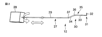
本実施の形態の処置具12は、電動で駆動される能動処置具(電動処置具)で構成されている。図2に示すように、能動処置具12は、内視鏡11の処置具挿通用のチャンネル20内に挿入される細長い挿入部27を有する。この挿入部27の基端部には、モータボックス(処置具動力手段)28が連結されている。挿入部27は、手元側に位置した長尺の可撓管(軟性部)29と、この可撓管29の先端に接続された湾曲部30と、この湾曲部30の先端に接続された先端処置部31とから構成される。
The
可撓管29は外力によって比較的柔らかに弾性的に曲がり得る可撓性部分である。湾曲部30は上記モータボックス28により強制的に湾曲される部分である。また、先端処置部31は、その能動処置具12に対応した処置機能を備える。本実施形態では処置機能の一例として例えば高周波ナイフ32を備える。
The
上記湾曲部30は図2に示すように複数、本実施の形態では2つの湾曲駒(関節駒)33,34によって構成した多関節式の湾曲機構35を備える。各湾曲駒33,34はいずれも環状の部材によって形成されている。各湾曲駒33,34は挿入部27の軸方向へ一列に同軸的に並べて配置されている。先端側から順番に第1湾曲駒33、第2湾曲駒34と称する。
As shown in FIG. 2, the bending
第1湾曲駒33の前端部には、先端処置部31が固定されている。第1湾曲駒33の後端部は、第1関節部(屈曲部)36を介して第2湾曲駒34の前端部に対して屈曲可能に連結されている。第2湾曲駒34の後端部は、第2関節部(屈曲部)37を介して可撓管29の前端部に対して屈曲可能に連結されている。
A
また、本実施の形態では、挿入部27内には、第1湾曲駒33と第2湾曲駒34とをそれぞれ個別的に屈曲させるための図示しないワイヤユニットが設けられている。各ワイヤユニットは、それぞれ一対の非伸縮性の操作ワイヤを一組として形成されている。
In the present embodiment, a wire unit (not shown) for individually bending the
第1湾曲駒33は、第1組目のワイヤユニットの2本の操作ワイヤによって駆動される。同様に、第2湾曲駒34は、第2組目のワイヤユニットの2本の操作ワイヤによって駆動される。
The
また、各操作ワイヤはそれぞれ別々の可撓性ガイドシース内に進退自在に挿通されている。各ガイドシースは例えば密巻きコイルまたは樹脂チューブ等のシース状の可撓性部材により形成されている。その可撓性部材のガイドシースの内孔によって各操作ワイヤを進退する向きにのみガイドする。 Each operation wire is inserted into a separate flexible guide sheath so as to freely advance and retract. Each guide sheath is formed of a sheath-like flexible member such as a closely wound coil or a resin tube. Each operation wire is guided only in the direction to advance and retract by the inner hole of the guide sheath of the flexible member.
各ガイドシースは、手元側のモータボックス28まで導かれる。これにより、各操作ワイヤはそれぞれ別々の可撓性ガイドシース内を通して個別的に手元側のモータボックス28まで導かれる。そして、2組のワイヤユニットをそれぞれ個別に独立に駆動することにより、第1湾曲駒33、第2湾曲駒34をそれぞれ個別的に回動させることができる。すなわち、第1組目のワイヤユニットの2本の操作ワイヤをそれぞれ押し引きすることにより第1湾曲駒33のみを個別に独立して第1関節部36を中心に回動して個別に屈曲させることができる。同様に、第2組目のワイヤユニットの2本の操作ワイヤにより第2湾曲駒34のみを個別に独立して第2関節部37を中心に回動して個別に屈曲させることができる。これにより、本実施の形態では第1関節部36と、第2関節部37の2つの関節をそれぞれ個別に独立に駆動可能な多関節式湾曲機構が形成されている。この多関節式湾曲機構の部分は柔軟な外皮(図示せず)によって被覆され、その全体が湾曲部30を構成している。なお、本実施の形態では多関節式湾曲機構35を2つの湾曲駒33,34によって構成した例を示したが、湾曲駒の数はこれに限定されるものではなく、3以上の湾曲駒を使用して多関節式湾曲機構35を構成してもよい。本実施の形態では、多関節式湾曲機構35は、33,34の湾曲駒を用いて湾曲機構を形成したが、屈曲するリンク機構を用いてもよい。
Each guide sheath is guided to the
能動処置具12のモータボックス28には湾曲部30の第1湾曲駒33と、第2湾曲駒34をそれぞれ個別的に回動駆動する湾曲部操作機構と、処置具12を挿入方向に動作するための図示しないモータと、処置具12を軸回り方向に動かすための図示しないモータとが内蔵されている。湾曲部操作機構は回動操作対象の第1湾曲駒33と第2湾曲駒34に対応した2組の操作ワイヤをそれぞれ押し引き操作する2つの駆動モータを備える。そして、2つの駆動モータを個別的に駆動して2組の操作ワイヤを押し引き操作するようになっている。
In the
また、本実施の形態の内視鏡処置システムは、図4に示すように処置具12の位置姿勢情報を獲得するための処置具位置姿勢情報獲得手段38と、処置具12を能動的に動作させる処置具動力手段である前記モータボックス28と、モータボックス28を制御する回転と押し込み制御装置(制御手段)39と、回転と押し込み制御装置39に指示入力信号を送るジョイスティック装置(処置具指示入力手段)40と、内視鏡11の位置姿勢情報を獲得する内視鏡位置姿勢情報獲得手段44とを備える。処置具位置姿勢情報獲得手段38は、上記湾曲部30の第1関節部36および第2関節部37の関節位置を直接的にセンシングするエンコーダやポテンシオのことである。なお、関節位置に接続されているワイヤの移動量を測定することによってもセンシングすることができる。
Further, the endoscope treatment system according to the present embodiment actively operates the treatment instrument position / posture information acquisition means 38 for obtaining position / posture information of the
また、ジョイスティック装置40は、ベース部材41と、このベース部材41の上面に傾動操作、押し込み操作、および軸回りの回転操作が可能に設けられたジョイスティック42とを有する。そして、ベース部材41の上面のジョイスティック42を操作する操作信号は、制御装置39に入力される。ここで、ジョイスティック装置40の処置具操作は次の通り行われる。すなわち、ジョイスティック42の傾動操作によって処置具12の湾曲部30の湾曲操作、押し込み操作によって処置具12の挿入、ジョイスティック42の軸回り方向の回転操作によって処置具12の軸回り方向の回転操作がそれぞれ行われる。この入力信号に応じて制御装置39によってモータボックス28の動作が制御されることにより、処置具12の湾曲部30が遠隔的に湾曲操作される。
The
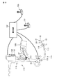
内視鏡位置姿勢情報獲得手段44は、図3に示すようにマウスピース45にフォトリフレクタ61を組み込んだものである。フォトリフレクタ61は、制御装置39に接続されている。
The endoscope position / orientation information acquisition means 44 includes a
さらに、内視鏡11は、挿入部13の外周面に縞模様62の付いた内視鏡を利用する。これにより、内視鏡11の挿入部13が動くことで、縞模様62をフォトリフレクタ61が感知し、内視鏡11の挿入部13の挿入量と、軸回り方向の回転量とを検知する。
Furthermore, the
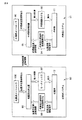
次に、上記構成の本実施の形態の内視鏡処置システムの作用について説明する。本実施の形態の内視鏡処置システムの使用時には、次の動作が行われる。 Next, the operation of the endoscope treatment system of the present embodiment having the above configuration will be described. When using the endoscope treatment system of the present embodiment, the following operation is performed.
(1)内視鏡11にて患部を観察する。
(1) The affected part is observed with the
(2)処置具12の挿入部27を内視鏡11のチャンネル20に挿通し、処置具制御がスタート。
(2) The
(3−1)術者は、ジョイスティック装置40のジョイスティック42を傾動操作することにより、処置具12の湾曲部30を湾曲操作するための指示を入力する。
(3-1) The surgeon inputs an instruction for bending the bending
(3−2)ジョイスティック装置40は、指示入力信号を制御装置39に送信する。これにより、モータボックス28の湾曲部操作機構によって湾曲部30の第1湾曲駒33と、第2湾曲駒34がそれぞれ個別的に回動駆動され、処置具12の湾曲部30がジョイスティック42の傾動操作に応じて湾曲操作される。
(3-2) The
(4)この処置具12の湾曲部30の湾曲操作時には、処置具位置姿勢情報獲得手段38によって処置具12の位置姿勢情報を獲得し、制御装置39に処置具位置姿勢情報を送信する。
(4) During the bending operation of the bending
(5−1)また、術者は、内視鏡11の視野を変更するため、内視鏡11の挿入部13を回転又は進退方向に操作する。
(5-1) Further, the operator operates the
(5−2)この内視鏡11の挿入部13の操作時には、内視鏡位置姿勢情報獲得手段44の挿入量検出部50と、回転量検出部51とによって内視鏡11の挿入部13の位置姿勢情報を獲得し、制御装置39に送信する。
(5-2) When the
(6)このとき、制御装置39は、上記(3−2)、(4)、(5−2)で受け取った各信号に基づいて計算し、モータボックス28を動力制御する。これにより、内視鏡位置姿勢情報獲得手段44からの位置姿勢情報を利用してモータボックス28の制御信号を調整する制御が行われる。
(6) At this time, the
(7)その後、モータボックス28から発生した動力は処置具12の湾曲部30に伝達されて、処置具12の湾曲部30が動作する。
(7) Thereafter, the power generated from the
以上の(3−1)〜(7)は一連の動作である。ここで、(6)における制御とは、内視鏡画像内における処置具12の湾曲部30の位置姿勢に対して、(5−1)の内視鏡11の挿入部13の操作から与える影響を打ち消す制御である。このことにより、術者は内視鏡11と処置具12とをそれぞれ独立した装置として操作することが可能となる。
The above (3-1) to (7) are a series of operations. Here, the control in (6) is the effect of the operation of the
そこで、上記構成のものにあっては次の効果を奏する。すなわち、本実施の形態の内視鏡装置1のシステムでは、軟性内視鏡11の挿入部13の位置情報をその内視鏡11のチャンネル20内に挿入される能動処置具12の制御に組み込んでいる。例えば、内視鏡11の挿入部13が動くことで、縞模様62を内視鏡位置姿勢情報獲得手段44のフォトリフレクタ61が感知し、内視鏡11の挿入部13の挿入量と、軸回り方向の回転量とを検知する。このとき、フォトリフレクタ61からの検出信号に基づいて軟性内視鏡11の挿入部13の挿入量x及び回転量αを検出した場合には、能動処置具12の制御時に、制御装置39によってモータボックス28の動作が次の通り制御される。すなわち、ジョイスティック装置40のジョイスティック42を押し込み、回転操作する操作にともない処置具12の挿入量yと回転量βの指示を受けて、また、軟性内視鏡11の挿入部13の挿入量がx変化し、軟性内視鏡11の挿入部13の回転量がα変化した場合に、制御装置39によって処置具12を挿入量zと回転量γだけ動かすようにモータボックス28の動作が制御される。このとき、制御装置39は、処置具12の挿入量zと処置具12の回転量γとが次の式の通りとなるようにモータボックス28の動作を制御する。
Therefore, the above configuration has the following effects. That is, in the system of the endoscope apparatus 1 according to the present embodiment, the position information of the
z=y−x
γ=β−α
これにより、軟性内視鏡11の位置が変化したときの能動処置具12の位置ずれを無くすことができる。したがって、能動処置具12の動作効率及び位置精度の向上を図ることができる。その結果、手技を行う際に内視鏡11と、内視鏡画像内における処置具12の位置姿勢を独立して操作することが可能となるうえ、また患部と処置具12の相対位置姿勢を変化させずに内視鏡11の位置姿勢を操作することが可能となる内視鏡処置システムを提供することができる。
z = y−x
γ = β-α
Thereby, the position shift of the
また、図5は、第1の実施の形態の内視鏡処置システムの内視鏡位置姿勢情報獲得手段44の第1の変形例を示す要部の概略構成図である。第1の実施の形態では、マウスピース45に、フォトリフレクタ61を組み込んだ構成を示した。本変形例は、これに代えて、次の構成を採用したものである。
FIG. 5 is a schematic configuration diagram of a main part showing a first modification of the endoscope position / orientation
すなわち、本変形例では、マウスピース45に内視鏡11の挿入部13が挿入された際に、内視鏡11の挿入部13と接触する2つ(第1,第2の)ローラ71,72がマウスピース45に組み込まれている。第1のローラ71は、内視鏡11の挿入部13が軸方向に移動することで回転するように支持されている。第2のローラ72は、内視鏡11の挿入部13が軸回り方向に移動することで回転するように支持されている。これにより、内視鏡11の挿入部13が挿入方向及びに回転方向に動くことで、各ローラが回転するようになっている。
That is, in this modification, when the
第1のローラ71には、第1の穴つきホイール73、第2のローラ72には第2の穴つきホイール74がそれぞれ付随されている。さらに、第1の穴つきホイール73の回転は、第1のフォトインタラプタ75、第2の穴つきホイール74の回転は、第2のフォトインタラプタ76がそれぞれ検知する。これら第1のフォトインタラプタ75と第2のフォトインタラプタ76とは制御装置39に接続されている。
The
そして、内視鏡11の挿入部13が軸方向に動くことで、第1のローラ71が回転し、この第1のローラ71と一緒に回転する第1の穴つきホイール73の回転が第1のフォトインタラプタ75によって感知される。さらに、内視鏡11の挿入部13が軸回り方向に動くことで、第2のローラ72が回転し、この第2のローラ72と一緒に回転する第2の穴つきホイール74の回転が第2のフォトインタラプタ76によって感知される。これにより、内視鏡11の挿入部13の挿入量と、軸回り方向の回転量とを検知する構成になっている。
The
図6は、第1の実施の形態の内視鏡処置システムの内視鏡位置姿勢情報獲得手段44の第2の変形例を示す要部の概略構成図である。本変形例では、LED光源81にて内視鏡11の挿入部13に光を当て、受光センサ82にて光の反射を測定する。この光の反射によって内視鏡11の挿入部13の凹凸や、模様を感知することによって、内視鏡11の挿入部13の挿入量と回転量を検知する構成になっている。
FIG. 6 is a schematic configuration diagram of a main part illustrating a second modification of the endoscope position / posture
また、図7乃至図9は本発明の第2の実施の形態を示す。図7は、本実施の形態の内視鏡処置システム全体の概略構成図、図8は、後述する内視鏡駆動装置43の一例の概略構成図、図9は内視鏡処置システム全体のブロック図である。なお、第1の実施の形態と同一部分には同一の符号を付してここではその説明を省略する。
7 to 9 show a second embodiment of the present invention. 7 is a schematic configuration diagram of the entire endoscope treatment system according to the present embodiment, FIG. 8 is a schematic configuration diagram of an example of an
本実施の形態の内視鏡処置システムは、図9に示すように第1の実施の形態(図1乃至図4参照)の内視鏡11を駆動する内視鏡システム91と、第1の実施の形態の能動処置具12を駆動する処置具システム92とを有する。
As shown in FIG. 9, the endoscope treatment system according to the present embodiment includes an
内視鏡システム91は、内視鏡11と、内視鏡動力手段93と、内視鏡11の位置姿勢情報を獲得する内視鏡位置姿勢情報獲得手段94と、内視鏡制御装置(内視鏡制御手段)95と、内視鏡コントローラ(内視鏡指示入力手段)96とを有する。
The
内視鏡動力手段93は、内視鏡11の挿入部13を直動及び回転動作させる動作、すなわち内視鏡11の挿入部13をこの挿入部13の軸方向に移動させる挿入部13の挿脱操作と、内視鏡11の挿入部13をこの挿入部13の軸回り方向に回転させる動作とを行う。
The endoscope power means 93 is an operation for linearly moving and rotating the
図8は、内視鏡11を駆動する内視鏡動力手段93である内視鏡駆動装置43の一例を示す。ここでは、内視鏡駆動装置43は、例えば患者の口に咥える状態で装着されるマウスピース45に組み込まれた2つ(第1,第2の)駆動モータ46,47と、第1の駆動モータ46の回転軸に固定された軸方向駆動ローラ48と、第2の駆動モータ47の回転軸に固定された軸回り方向駆動ローラ49とを有する。第1,第2の駆動モータ46,47は、前記制御装置39に接続されている。軸方向駆動ローラ48は、第1の駆動モータ46の回転にともないマウスピース45に挿入される内視鏡11の挿入部13をこの挿入部13の軸方向に移動させる動作、すなわち内視鏡11の挿入部13の挿脱操作を行う。軸回り方向駆動ローラ49は、第2の駆動モータ47の回転にともないマウスピース45に挿入される内視鏡11の挿入部13をこの挿入部13の軸回り方向に回転させる動作を行う。
FIG. 8 shows an example of an
内視鏡位置姿勢情報獲得手段94は、内視鏡11の挿入部13の挿入量を検出する挿入量検出部50と、内視鏡11の挿入部13の軸回り方向の回転量を検出する回転量検出部51とを有する。挿入量検出部50は、第1の駆動モータ46の回転量を検出する図示しないエンコーダを有する。回転量検出部51は、第2の駆動モータ47の回転量を検出する図示しないエンコーダを有する。挿入量検出部50と、回転量検出部51とは、前記内視鏡制御装置95に接続されている。
The endoscope position / orientation information acquisition means 94 detects the amount of rotation of the
そして、内視鏡位置姿勢情報獲得手段94は、挿入量検出部50と回転量検出部51の各エンコーダからの検出信号に基づいて軟性内視鏡11の挿入部13の挿入量x及び回転量αを検出する。これにより、軟性内視鏡11の挿入部13の位置姿勢情報が内視鏡位置姿勢情報獲得手段94によって検出される。このとき、前記内視鏡制御装置95は、内視鏡位置姿勢情報獲得手段94からの位置姿勢情報を利用してモータボックス97の制御信号を調整する制御信号調整手段を有する。例えば、ジョイスティック装置40のジョイスティック42を回転と押し込み操作する操作にともない処置具12の挿入量yと回転量βの指示を受けた場合には、処置具制御装置99によって処置具12を挿入量zと回転量γだけ動かすようにモータボックス97の動作が制御される。このとき、処置具制御装置99は、処置具12の挿入量zと処置具12の回転量γとが次の式の通りとなるようにモータボックス97の動作を制御する。
The endoscope position / posture
z=y−x
γ=β−α
内視鏡コントローラ96は、例えば、ジョイスティック装置によって形成されている。さらに、内視鏡制御装置95には、内視鏡コントローラ96と、内視鏡動力手段93と、内視鏡位置姿勢情報獲得手段94とがそれぞれ接続されている。そして、術者が内視鏡コントローラ96を操作することにより、内視鏡制御装置95に指示入力信号が送られる。この指示入力信号に基づいて内視鏡制御装置95によって内視鏡動力手段93が制御され、内視鏡11の挿入部13を直動及び回転動作させる動作が行われる。このとき、内視鏡位置姿勢情報獲得手段94によって内視鏡11の挿入部13の位置姿勢情報が獲得される。
z = y−x
γ = β-α
The
また、処置具システム92は、処置具12と、第1の実施の形態のモータボックス28と同様の構成のモータボックス97と、処置具12の位置姿勢情報を獲得するための処置具位置姿勢情報獲得手段98と、内視鏡動力手段93及びモータボックス97を制御する処置具制御装置(処置具制御手段)99と、処置具制御装置99に指示入力信号を送るジョイスティック装置である処置具コントローラ(処置具指示入力手段)100とを備える。
The
そして、処置具コントローラ100を操作することにより、処置具制御装置99に指示入力信号が送られる。この指示入力信号に基づいて処置具制御装置99によってモータボックス97が制御され、このモータボックス97によって処置具12の湾曲部30の動作が行われる。このとき、処置具位置姿勢情報獲得手段98によって処置具12の湾曲部30の位置姿勢情報が獲得される。
Then, by operating the
また、処置具システム92は、前記内視鏡システム91と前記内視鏡位置姿勢情報を通信し、処置具制御装置99は、モータボックス97を前記内視鏡動力手段93と協調させて制御する構成になっている。なお、内視鏡制御装置95と、処置具制御装置99とは1つの制御装置101内に組み込まれている。
The
次に、上記構成の本実施の形態の内視鏡処置システムの作用について説明する。本実施の形態の内視鏡処置システムの使用時には、次の動作が行われる。 Next, the operation of the endoscope treatment system of the present embodiment having the above configuration will be described. When using the endoscope treatment system of the present embodiment, the following operation is performed.
(1)内視鏡制御装置95の動作がスタートし、内視鏡11にて患部を観察する。
(1) The operation of the
(2)処置具12の挿入部27を内視鏡11のチャンネル20に挿通し、処置具制御がスタート。
(2) The
(3−1)術者は、処置具コントローラ100に処置具12の挿入操作、回転操作と、処置具12の湾曲部30を湾曲操作するための指示を入力する。
(3-1) The operator inputs an operation for inserting and rotating the
(3−2)処置具コントローラ100は、指示入力信号を処置具制御装置99に送信する。これにより、モータボックス97の湾曲部操作機構によって湾曲部30の第1湾曲駒33と、第2湾曲駒34がそれぞれ個別的に回動駆動され、処置具12の湾曲部30が処置具コントローラ100の操作に応じて湾曲操作される。また、モータボックス97の処置具操作機構によって処置具12が回転及び挿入駆動され、処置具12が処置具コントローラ100の操作に応じて回転及び挿入操作される。
(3-2) The
(4)この処置具12の挿入操作、回転操作と、処置具12の湾曲部30の湾曲操作時には、処置具位置姿勢情報獲得手段98によって処置具12の位置姿勢情報を獲得し、処置具制御装置99に処置具位置姿勢情報を送信する。
(4) During the insertion operation and rotation operation of the
(5−1)術者は、内視鏡11の視野を変更するため、内視鏡コントローラ96を操作する。
(5-1) The operator operates the
(5−2)このとき、内視鏡コントローラ96は、内視鏡指示入力信号を内視鏡制御装置95に送信する。
(5-2) At this time, the
(6)これにより、内視鏡位置姿勢情報獲得手段94は、内視鏡11の挿入部13の位置姿勢情報を獲得し、内視鏡制御装置95及び処置具制御装置99に送信する。
(6) Thereby, the endoscope position / posture
(7)内視鏡制御装置95は、上記(5−2)、(6)で受け取った信号に基づいて計算し、内視鏡動力手段93を動力制御する。これにより、内視鏡位置姿勢情報獲得手段94からの位置姿勢情報を利用してモータボックス97の制御信号を調整する制御が行われる。
(7) The
(8)その後、内視鏡動力手段93から発生した動力は内視鏡11の挿入部13に伝達されて、内視鏡11の挿入部13は進退・回転方向に動作する。
(8) Thereafter, the power generated from the endoscope power means 93 is transmitted to the
(9)続いて、制御装置39は、上記(3−2)、(4)、(6)で受け取った各信号に基づいて計算し、モータボックス97を動力制御する。
(9) Subsequently, the
(10)このとき、モータボックス97から発生した動力は処置具12に伝達されて、処置具12が挿入、回転動作し、また処置具12の湾曲部30が動作する。
(10) At this time, the power generated from the
以上の(3−1)〜(10)は一連の動作である。ここで、(9)におけるモータボックス97の動力制御とは、内視鏡画像内における処置具12の位置姿勢に対して、(5−1)の内視鏡操作から与える影響を打ち消す制御である。これにより、術者は内視鏡11と処置具12を独立した装置として操作することが可能となる。
The above (3-1) to (10) are a series of operations. Here, the power control of the
そこで、上記構成の本実施の形態でも、手技を行う際に内視鏡11と、内視鏡画像内における処置具12の位置姿勢を独立して操作することが可能となるうえ、また患部と処置具12の相対位置姿勢を変化させずに内視鏡11の位置姿勢を操作することが可能となる内視鏡処置システムを提供することができる。これにより、内視鏡11の動きと処置具12の動きを同期させることが出来るため手技を行う際に常に内視鏡11の視野内に処置具12を配置することができる。そのため、従来のように内視鏡11と処置具12とを組み合わせて使用する使用時に、内視鏡11が動くことで、内視鏡画像内における処置具12の位置が全く異なってしまうことを防止することができる。
Therefore, even in the present embodiment configured as described above, it is possible to independently operate the position and orientation of the
また、図10および図11は本発明の第3の実施の形態を示す。図10は、本実施の形態の内視鏡処置システム全体の概略構成図、図11は同ブロック図である。なお、第1の実施の形態と同一部分には同一の符号を付してここではその説明を省略する。 10 and 11 show a third embodiment of the present invention. FIG. 10 is a schematic configuration diagram of the entire endoscope treatment system according to the present embodiment, and FIG. 11 is a block diagram thereof. The same parts as those in the first embodiment are denoted by the same reference numerals, and the description thereof is omitted here.
本実施の形態の内視鏡処置システムは、図11に示す内視鏡システム111と、第1の実施の形態の能動処置具12を駆動する処置具システム112とを有する。本実施の形態の内視鏡システム111では、第1の実施の形態(図1乃至図4参照)のように湾曲部16を手動操作によって湾曲操作する手動湾曲式の内視鏡11に代えて図示しないモータからの駆動力によって図示しない操作ワイヤを牽引して能動的に駆動可能な能動湾曲部113を有する能動内視鏡114を使用している。
The endoscope treatment system according to the present embodiment includes the
図10に示すように能動内視鏡114は、体内に挿入される細長い挿入部115と、この挿入部115の基端部に連結された操作部116とを有する。挿入部115は、細長い可撓管部117と、可撓管部117の先端に連結された前記能動湾曲部113と、湾曲部113の先端に連結された先端硬性部118とを有する。湾曲部113は、例えば上下方向および左右方向の4方向にそれぞれ湾曲操作可能になっている。
As shown in FIG. 10, the
先端硬性部118の先端面には、第1の実施の形態と同様に例えば1つの観察窓部18と、2つの照明窓部19a,19bと、1つの処置具挿通用のチャンネル20の開口部と、1つの送気送水ノズル21と(いずれも図1(B)に示す)を有する。観察窓部18の内側には、図示しない対物レンズ等の光学系およびCCD等の撮像素子を備えた撮像部が配設されている。この撮像部によって体腔内の病変部等が撮像される。そして、内視鏡114の撮像部で得られた撮像信号は接続ケーブルを通じて図示しない表示用プロセッサに送られ、映像信号に変換され、この映像信号によって内視鏡114で撮影した像を図示しない表示装置に映し出すようになっている。
As in the first embodiment, for example, one
操作部116には、送気送水ボタン119と、吸引ボタン120と、撮像操作用の各種のスイッチなどが配設されている。さらに、操作部116と挿入部115との連結部の近傍には、処置具挿通用のチャンネル20と連通するチャンネル口121が形成されている。このチャンネル口121には処置具12が挿入されるようになっている。
The
また、本実施の形態の内視鏡システム111は、前記内視鏡114と、内視鏡動力手段122と、内視鏡114の位置姿勢情報を獲得する内視鏡位置姿勢情報獲得手段123と、内視鏡制御装置(内視鏡制御手段)124と、内視鏡コントローラ(内視鏡指示入力手段)125と、湾曲部動力手段126と、内視鏡湾曲情報獲得手段127と、を有する。
The
内視鏡動力手段122は、内視鏡114の挿入部115を直動及び回転動作させる動作、すなわち内視鏡114の挿入部115をこの挿入部115の軸方向に移動させる挿入部115の挿脱操作と、内視鏡114の挿入部115をこの挿入部115の軸回り方向に回転させる動作とを行う。内視鏡位置姿勢情報獲得手段123は、例えば第1の実施の形態と同様に、内視鏡114の挿入部115の挿入量を検出する挿入量検出部50(図3参照)と、内視鏡114の挿入部115の軸回り方向の回転量を検出する回転量検出部51(図3参照)とを有し、内視鏡114の挿入部115の位置姿勢情報を獲得する。
The
内視鏡コントローラ125は、例えば、ジョイスティック装置によって形成されている。さらに、内視鏡制御装置124には、内視鏡コントローラ125と、内視鏡動力手段122と、内視鏡位置姿勢情報獲得手段123とがそれぞれ接続されている。そして、術者が内視鏡コントローラ125を操作することにより、内視鏡制御装置124に指示入力信号が送られる。この指示入力信号に基づいて内視鏡制御装置124によって内視鏡動力手段122が制御され、内視鏡114の挿入部115を直動及び回転動作させる動作が行われる。このとき、内視鏡位置姿勢情報獲得手段123によって内視鏡114の挿入部115の位置姿勢情報が獲得される。
The
また、内視鏡コントローラ125のジョイスティック装置によって内視鏡制御装置124に指示入力信号が送られる。この指示入力信号に基づいて内視鏡制御装置124によって湾曲部動力手段126が制御され、この湾曲部動力手段126によって湾曲部113の動作が行われる。このとき、内視鏡湾曲情報獲得手段127によって湾曲部113の位置姿勢情報が獲得される。
Also, an instruction input signal is sent to the
また、処置具システム112は、前記能動処置具12と、第1の実施の形態のモータボックス28と同様の構成のモータボックス128と、処置具12の位置姿勢情報を獲得するための処置具位置姿勢情報獲得手段129と、内視鏡動力手段122及びモータボックス128を制御する処置具制御装置(処置具制御手段)130と、処置具制御装置130に指示入力信号を送るジョイスティック装置である処置具コントローラ(処置具指示入力手段)131とを備える。
In addition, the
そして、処置具コントローラ131のジョイスティック装置を操作することにより、処置具制御装置130に湾曲部30を湾曲操作する指示入力信号が送られる。この指示入力信号に基づいて処置具制御装置130によってモータボックス128が制御され、このモータボックス128によって処置具12の湾曲部30の動作が行われる。このとき、処置具位置姿勢情報獲得手段129によって処置具12の湾曲部30の位置姿勢情報が獲得される。
Then, by operating the joystick device of the
また、処置具システム112は、内視鏡システム111と内視鏡位置姿勢情報を通信し、処置具制御装置130は、モータボックス128を前記内視鏡動力手段122と協調させて制御する構成になっている。なお、内視鏡制御装置124と、処置具制御装置130とは1つの制御装置132内に組み込まれている。
Further, the
次に、上記構成の本実施の形態の内視鏡処置システムの作用について説明する。本実施の形態の内視鏡処置システムの使用時には、次の動作が行われる。 Next, the operation of the endoscope treatment system of the present embodiment having the above configuration will be described. When using the endoscope treatment system of the present embodiment, the following operation is performed.
(1)内視鏡制御装置124の動作がスタートし、内視鏡114にて患部を観察する。
(1) The operation of the
(2)処置具12の挿入部27を内視鏡114のチャンネル20に挿通し、処置具制御がスタート。
(2) The
(3−1)術者は、処置具コントローラ131に処置具12の挿入操作、回転操作と、処置具12の湾曲部30を湾曲操作するための指示を入力する。
(3-1) The surgeon inputs an operation for inserting and rotating the
(3−2)処置具コントローラ131は、指示入力信号を処置具制御装置130に送信する。これにより、モータボックス128の湾曲部操作機構によって湾曲部30の第1湾曲駒33と、第2湾曲駒34がそれぞれ個別的に回動駆動され、処置具12の湾曲部30が処置具コントローラ131の操作に応じて湾曲操作される。また、モータボックス128の処置具操作機構によって処置具12が回転及び挿入駆動され、処置具12が処置具コントローラ131の操作に応じて回転及び挿入操作される。
(3-2) The
(4)このとき、処置具位置姿勢情報獲得手段129は、処置具12の位置姿勢情報を獲得し、処置具制御装置130に処置具位置姿勢情報を送信する。
(4) At this time, the treatment instrument position / posture information acquisition unit 129 acquires the position / posture information of the
(5−1)術者は、内視鏡114の視野を変更するため、内視鏡コントローラ125を操作する。
(5-1) The operator operates the
(5−2)内視鏡コントローラ125は、内視鏡指示入力信号を内視鏡制御装置124に送信する。
(5-2) The
(6)内視鏡位置姿勢情報獲得手段123は、内視鏡114の挿入部115の位置姿勢情報を獲得し、内視鏡制御装置124及び処置具制御装置130に送信する。
(6) The endoscope position / posture
(7)内視鏡湾曲情報獲得手段127は、内視鏡湾曲部113の湾曲情報を獲得し、内視鏡制御装置124及び処置具制御装置130に送信する。
(7) The endoscope bending
(8)内視鏡制御装置124は、(5)、(6)、(7)で受け取った信号に基づいて計算し、内視鏡動力手段122を動力制御し、また湾曲部動力手段126を動力制御する。これにより、内視鏡位置姿勢情報獲得手段123からの位置姿勢情報を利用してモータボックス128の制御信号を調整する制御が行われる。
(8) The
(9)内視鏡動力手段122から発生した動力は内視鏡114の挿入部115に伝達されて、内視鏡114の挿入部115は進退・回転方向に動作する。
(9) The power generated from the endoscope power means 122 is transmitted to the
(10)その後、湾曲部動力手段126から発生した動力は内視鏡湾曲部113に伝達されて、内視鏡114の湾曲部113は湾曲動作する。
(10) Thereafter, the power generated from the bending portion power means 126 is transmitted to the
(11)処置具制御装置130は、上記(3−2)、(4)、(6)で受け取った各信号に基づいて計算し、モータボックス128を動力制御する。
(11) The treatment
(12)モータボックス128から発生した動力は処置具12に伝達されて、処置具12の湾曲部30が動作する。
(12) The power generated from the
以上の(3−1)〜(10)は一連の動作である。ここで、(9)における制御とは、内視鏡画像内における処置具12の位置姿勢に対して、(5−1)の内視鏡操作から与える影響を打ち消す制御である。これにより、術者は内視鏡114と処置具12を独立した装置として操作することが可能となる。
The above (3-1) to (10) are a series of operations. Here, the control in (9) is control for canceling the influence of the endoscope operation in (5-1) on the position and orientation of the
そこで、上記構成の本実施の形態でも、手技を行う際に内視鏡114と、内視鏡画像内における処置具12の位置姿勢を独立して操作することが可能となるうえ、また患部と処置具12の相対位置姿勢を変化させずに内視鏡114の位置姿勢を操作することが可能となる内視鏡処置システムを提供することができる。これにより、内視鏡114が動いたときに、軟性鏡用能動駆動式処置具12も連動して動作することで、内視鏡114と軟性鏡用能動駆動式処置具12との間に発生する、術者の意図しない相対的なずれを無くす。つまり、内視鏡114が動いたときに、軟性鏡画像内において軟性鏡用能動駆動式処置具12が固定したままの状態に映るようにすることができる。
Therefore, even in the present embodiment configured as described above, it is possible to independently operate the position and orientation of the
さらに、本発明は上記実施の形態に限定されるものではなく、本発明の要旨を逸脱しない範囲で種々変形実施できることは勿論である。
次に、本出願の他の特徴的な技術事項を下記の通り付記する。
記
(付記項1) 被検体を処置する処置手段と、前記処置手段を能動的に動作させる動力手段と、前記動力手段を制御するための制御手段と、前記処置手段を挿入して用いる軟性の内視鏡と、前記内視鏡の位置情報を測定する測定手段と、前記測定手段の位置情報を前記制御手段の制御に取り入れることを特徴とする軟性鏡用能動駆動式処置具装置。
Furthermore, the present invention is not limited to the above-described embodiment, and various modifications can be made without departing from the scope of the present invention.
Next, other characteristic technical matters of the present application are appended as follows.
Record
(Additional Item 1) Treatment means for treating a subject; power means for actively operating the treatment means; control means for controlling the power means; An active drive treatment instrument device for a flexible endoscope, comprising: an endoscope; measurement means for measuring position information of the endoscope; and position information of the measurement means taken into control of the control means.
(付記項2) 前記測定手段は、前記内視鏡の挿入量及び回転量を検出するマウスピースであることを特徴とした付記項1に記載の軟性鏡用能動駆動式処置具装置。 (Additional Item 2) The active drive type treatment instrument device for a flexible endoscope according to Additional Item 1, wherein the measurement unit is a mouthpiece that detects an insertion amount and a rotation amount of the endoscope.
(付記項3) 内視鏡のチャンネル内に挿通可能であって被検体を処置する処置手段と、前記内視鏡の位置情報を測定する位置情報測定手段と、測定された前記位置情報に基づき前記処置手段の位置を制御する制御手段と、を有することを特徴とする内視鏡装置。 (Additional Item 3) Based on the measured position information, treatment means that can be inserted into the channel of the endoscope and treats the subject, position information measurement means that measures position information of the endoscope, and An endoscopic device comprising: control means for controlling the position of the treatment means.
(付記項4) 内視鏡のチャンネル内に挿通可能であって被検体を処置する処置手段と、前記処置手段の位置情報を測定する位置情報測定手段と、測定された前記位置情報に基づき前記内視鏡の位置を制御する制御手段と、を有することを特徴とする内視鏡装置。 (Additional Item 4) Treatment means that can be inserted into a channel of an endoscope and that treats a subject, position information measurement means that measures position information of the treatment means, and based on the measured position information, An endoscope apparatus comprising: a control unit that controls the position of the endoscope.
(付記項5) 内視鏡と、前記内視鏡又は前記内視鏡に装着されたオーバーチューブのチャンネル内に挿通可能であって被検体を処置する処置手段と、前記処置手段の位置姿勢情報を獲得するための処置具位置姿勢情報獲得手段と、前記処置手段を能動的に動作させる処置具動力手段と、前記処置具動力手段を制御する制御手段と、前記制御手段に指示入力信号を送る処置具指示入力手段を備える内視鏡処置システムにおいて、前記内視鏡の位置姿勢情報を獲得する内視鏡位置姿勢情報獲得手段を有し、前記制御手段は前記位置姿勢情報を利用することを特徴とする内視鏡処置システム。 (Additional Item 5) An endoscope, treatment means that can be inserted into the endoscope or a channel of an overtube attached to the endoscope, and treats a subject, and position and orientation information of the treatment means Treatment tool position / posture information acquisition means for obtaining the treatment tool, treatment tool power means for actively operating the treatment means, control means for controlling the treatment tool power means, and sending an instruction input signal to the control means An endoscopic treatment system including a treatment instrument instruction input unit includes an endoscope position / posture information acquisition unit that acquires position / posture information of the endoscope, and the control unit uses the position / posture information. Endoscopic treatment system characterized.
(付記項6) 内視鏡と、前記内視鏡の位置姿勢情報を獲得するための内視鏡位置姿勢情報獲得装置と、前記内視鏡を直動及び回転動作させる内視鏡動力手段と、前記内視鏡動力手段を制御する内視鏡制御手段と、前記内視鏡制御手段に指示入力信号を送るための内視鏡指示入力手段を備える内視鏡システムを有し、かつ前記内視鏡、又は前記内視鏡に装着されたオーバーチューブのチャンネル内に挿通可能であって被検体を処置する処置手段と、前記処置手段の位置姿勢情報を獲得するための処置具位置姿勢情報獲得手段と、前記処置手段を能動的に動作させる処置具動力手段と、前記処置具動力手段を制御する処置具制御手段と、前記処置具制御手段に指示入力信号を送るための処置具指示入力手段と、前記内視鏡動力手段及び前記処置具動力手段を制御するための処置具制御手段を備える処置システムを有する、内視鏡処置システムにおいて、前記処置システムは前記内視鏡システムと内視鏡位置姿勢情報を通信し、前記処置具制御手段は、前記処置具動力手段を前記内視鏡動力手段と協調させて制御することを特徴とする内視鏡処置システム。 (Additional Item 6) An endoscope, an endoscope position / orientation information acquisition device for acquiring position and orientation information of the endoscope, and an endoscope power unit that linearly and rotationally operates the endoscope An endoscope system comprising: an endoscope control means for controlling the endoscope power means; and an endoscope instruction input means for sending an instruction input signal to the endoscope control means; and A treatment means that can be inserted into an endoscope or a channel of an overtube attached to the endoscope and treats a subject, and treatment tool position / posture information acquisition for obtaining position / posture information of the treatment means Means, a treatment tool power means for actively operating the treatment means, a treatment tool control means for controlling the treatment tool power means, and a treatment tool instruction input means for sending an instruction input signal to the treatment tool control means The endoscope power means and the treatment An endoscope treatment system having a treatment system including treatment tool control means for controlling power means, wherein the treatment system communicates endoscope position and orientation information with the endoscope system, and the treatment tool control means The endoscope treatment system is characterized in that the treatment instrument power means is controlled in cooperation with the endoscope power means.
(付記項7) 能動湾曲部を有する内視鏡と、前記内視鏡の位置姿勢情報を獲得するための内視鏡位置姿勢情報獲得装置と、前記内視鏡を直動及び回転動作させる内視鏡動力手段と、前記湾曲部の湾曲情報を獲得するための内視鏡湾曲情報獲得装置と、前記内視鏡の能動湾曲部を湾曲動作させるための湾曲部動力手段と、前記内視鏡動力手段及び前記湾曲部動力手段を制御する内視鏡制御手段と、前記内視鏡制御手段に指示入力信号を送るための内視鏡指示入力手段を備える内視鏡システムを有し、かつ前記内視鏡、又は前記内視鏡に装着されたオーバーチューブのチャンネル内に挿通可能であって被検体を処置する処置手段と、前記処置手段の位置姿勢情報を獲得するための処置具位置姿勢情報獲得手段と、前記処置手段を能動的に動作させる処置具動力手段と、前記処置具動力手段を制御する処置具制御手段と、前記処置具制御手段に指示入力信号を送るための処置具指示入力手段と、前記内視鏡動力手段及び前記処置具動力手段を制御するための処置具制御手段を備える処置システムを有する、内視鏡処置システムにおいて、前記処置システムは前記内視鏡システムと内視鏡位置姿勢情報を通信し、前記処置具制御手段は、前記処置具動力手段を前記内視鏡動力手段と協調させて制御することを特徴とする内視鏡処置システム。 (Additional Item 7) An endoscope having an active bending portion, an endoscope position / posture information acquisition device for acquiring position / posture information of the endoscope, and an endoscope in which the endoscope is linearly moved and rotated. Endoscopic power means, endoscope bending information acquisition device for acquiring bending information of the bending part, bending part power means for bending the active bending part of the endoscope, and the endoscope An endoscope system comprising: endoscope control means for controlling the power means and the bending portion power means; and an endoscope instruction input means for sending an instruction input signal to the endoscope control means, and Treatment means that can be inserted into an endoscope or a channel of an overtube attached to the endoscope and treats a subject, and treatment instrument position / posture information for acquiring position / posture information of the treatment means The acquisition means and the treatment means are actively operated. Treatment tool power means, treatment tool control means for controlling the treatment tool power means, treatment tool instruction input means for sending an instruction input signal to the treatment tool control means, the endoscope power means and the treatment An endoscope treatment system having a treatment system including treatment tool control means for controlling tool power means, wherein the treatment system communicates endoscope position and orientation information with the endoscope system, and the treatment tool control The means controls the treatment instrument powering means in cooperation with the endoscope powering means.
本発明は、内視鏡のチャンネル内に処置具が挿通され、内視鏡の観察視野内に処置具の先端部を表示させることにより、処置具による処置状態を内視鏡画像で確認しながら体内の処置を行う内視鏡処置システムの分野、この内視鏡処置システムを製造、使用する技術分野に有効である。 In the present invention, a treatment tool is inserted into a channel of an endoscope, and a distal end portion of the treatment tool is displayed in an observation field of the endoscope, thereby confirming a treatment state by the treatment tool with an endoscope image. The present invention is effective in the field of endoscopic treatment systems that perform treatment in the body, and in the technical field in which this endoscopic treatment system is manufactured and used.
11…内視鏡、12…処置具、20…チャンネル、28…モータボックス(処置具動力手段)、38…処置具位置姿勢情報獲得手段、39…制御装置(制御手段)、40…ジョイスティック装置(処置具指示入力手段)、44…内視鏡位置姿勢情報獲得手段。
DESCRIPTION OF
Claims (3)
前記内視鏡のチャンネル内に挿通可能であって被検体を処置する処置具と、
前記処置具の位置姿勢情報を獲得するための処置具位置姿勢情報獲得手段と、
前記処置具を能動的に動作させる処置具動力手段と、
前記処置具動力手段を制御する制御手段と、
前記制御手段に指示入力信号を送る処置具指示入力手段を備える内視鏡処置システムにおいて、
前記制御手段に接続され、前記内視鏡の位置姿勢情報を獲得する内視鏡位置姿勢情報獲得手段を設け、
前記制御手段は、前記位置姿勢情報を利用して前記処置具動力手段の制御信号を調整し、前記内視鏡画像内における前記処置具の位置姿勢に対して、前記内視鏡の操作から与える影響を打ち消す状態で前記内視鏡画像内における前記処置具の位置姿勢を独立して操作する制御信号調整手段を有することを特徴とする内視鏡処置システム。 An endoscope,
A treatment instrument that can be inserted into a channel of the endoscope and treats a subject;
A treatment instrument position and orientation information acquisition means for acquiring position and orientation information of the treatment instrument;
Treatment instrument power means for actively operating the treatment instrument;
Control means for controlling the treatment instrument power means;
In an endoscope treatment system comprising a treatment instrument instruction input means for sending an instruction input signal to the control means,
An endoscope position / orientation information acquisition unit that is connected to the control unit and acquires the position / orientation information of the endoscope;
The control means adjusts a control signal of the treatment tool power means using the position and orientation information, and gives the position and orientation of the treatment tool in the endoscope image from the operation of the endoscope. An endoscopic treatment system comprising control signal adjusting means for independently operating the position and orientation of the treatment tool in the endoscopic image in a state where the influence is canceled .
前記内視鏡システムは、内視鏡と、
前記内視鏡の挿入部の位置姿勢情報を獲得するための内視鏡位置姿勢情報獲得装置と、
前記内視鏡の挿入部を直動及び回転動作させる内視鏡動力手段と、
前記内視鏡動力手段を制御する内視鏡制御手段と、
前記内視鏡制御手段に指示入力信号を送るための内視鏡指示入力手段と、を具備し、
前記処置システムは、前記内視鏡のチャンネル内に挿通可能であって被検体を処置する処置具と、
前記処置具の位置姿勢情報を獲得するための処置具位置姿勢情報獲得手段と、
前記処置具を能動的に動作させる処置具動力手段と、
前記処置具動力手段を制御する処置具制御手段と、
前記処置具制御手段に指示入力信号を送るための処置具指示入力手段と、
前記内視鏡動力手段及び前記処置具動力手段を制御するための処置具制御手段と、を具備する内視鏡処置システムにおいて、
前記処置システムは、前記内視鏡システムと前記内視鏡位置姿勢情報を通信し、
前記処置具制御手段は、前記処置具動力手段を前記内視鏡動力手段と協調させて制御し、前記内視鏡画像内における前記処置具の位置姿勢に対して、前記内視鏡の操作から与える影響を打ち消す状態で前記内視鏡画像内における前記処置具の位置姿勢を独立して操作することを特徴とする内視鏡処置システム。 An endoscope system and a treatment system;
The endoscope system includes an endoscope,
An endoscope position and orientation information acquisition device for acquiring position and orientation information of the insertion portion of the endoscope;
Endoscope power means for linearly moving and rotating the insertion portion of the endoscope;
Endoscope control means for controlling the endoscope power means;
An endoscope instruction input means for sending an instruction input signal to the endoscope control means,
The treatment system includes a treatment tool that can be inserted into a channel of the endoscope and treats a subject;
A treatment instrument position and orientation information acquisition means for acquiring position and orientation information of the treatment instrument;
Treatment instrument power means for actively operating the treatment instrument;
Treatment instrument control means for controlling the treatment instrument power means;
A treatment instrument instruction input means for sending an instruction input signal to the treatment instrument control means;
In an endoscope treatment system comprising the endoscope power means and a treatment tool control means for controlling the treatment tool power means,
The treatment system communicates the endoscope position and orientation information with the endoscope system,
The treatment tool control means controls the treatment tool power means in cooperation with the endoscope power means, and operates the endoscope with respect to the position and orientation of the treatment tool in the endoscopic image. An endoscopic treatment system, wherein the position and orientation of the treatment tool in the endoscopic image are independently operated in a state in which the influence exerted is canceled .
前記内視鏡システムは、管腔内に挿入される挿入部の先端部に能動湾曲部を有する内視鏡と、
前記内視鏡の挿入部の位置姿勢情報を獲得するための内視鏡位置姿勢情報獲得装置と、
前記内視鏡の挿入部を直動及び回転動作させる内視鏡動力手段と、
前記湾曲部の湾曲情報を獲得するための内視鏡湾曲情報獲得装置と、
前記内視鏡の能動湾曲部を湾曲動作させるための湾曲部動力手段と、
前記内視鏡動力手段及び前記湾曲部動力手段を制御する内視鏡制御手段と、
前記内視鏡制御手段に指示入力信号を送るための内視鏡指示入力手段と、を具備し、
前記処置システムは、前記内視鏡のチャンネル内に挿通可能であって被検体を処置する処置具と、
前記処置具の位置姿勢情報を獲得するための処置具位置姿勢情報獲得手段と、
前記処置具を能動的に動作させる処置具動力手段と、
前記処置具動力手段を制御する処置具制御手段と、
前記処置具制御手段に指示入力信号を送るための処置具指示入力手段と、
前記内視鏡動力手段及び前記処置具動力手段を制御するための処置具制御手段と、を具備する内視鏡処置システムにおいて、
前記処置システムは前記内視鏡システムと内視鏡位置姿勢情報を通信し、
前記処置具制御手段は、前記処置具動力手段を前記内視鏡動力手段と協調させて制御し、前記内視鏡画像内における前記処置具の位置姿勢に対して、前記内視鏡の操作から与える影響を打ち消す状態で前記内視鏡画像内における前記処置具の位置姿勢を独立して操作することを特徴とする内視鏡処置システム。 An endoscope system and a treatment system;
The endoscope system includes an endoscope having an active bending portion at a distal end portion of an insertion portion to be inserted into a lumen;
An endoscope position and orientation information acquisition device for acquiring position and orientation information of the insertion portion of the endoscope;
Endoscope power means for linearly moving and rotating the insertion portion of the endoscope;
An endoscope bending information acquisition device for acquiring bending information of the bending portion;
A bending portion power means for bending the active bending portion of the endoscope;
Endoscope control means for controlling the endoscope power means and the bending portion power means;
An endoscope instruction input means for sending an instruction input signal to the endoscope control means,
The treatment system includes a treatment tool that can be inserted into a channel of the endoscope and treats a subject;
A treatment instrument position and orientation information acquisition means for acquiring position and orientation information of the treatment instrument;
Treatment instrument power means for actively operating the treatment instrument;
Treatment instrument control means for controlling the treatment instrument power means;
A treatment instrument instruction input means for sending an instruction input signal to the treatment instrument control means;
In an endoscope treatment system comprising the endoscope power means and a treatment tool control means for controlling the treatment tool power means,
The treatment system communicates endoscope position and orientation information with the endoscope system,
The treatment tool control means controls the treatment tool power means in cooperation with the endoscope power means, and operates the endoscope with respect to the position and orientation of the treatment tool in the endoscopic image. An endoscopic treatment system, wherein the position and orientation of the treatment tool in the endoscopic image are independently operated in a state in which the influence exerted is canceled .
Priority Applications (4)
| Application Number | Priority Date | Filing Date | Title |
|---|---|---|---|
| JP2008191041A JP5384869B2 (en) | 2008-07-24 | 2008-07-24 | Endoscopic treatment system |
| US12/491,482 US20100022825A1 (en) | 2008-07-24 | 2009-06-25 | Endoscopic surgical system |
| EP09008453.4A EP2147630B1 (en) | 2008-07-24 | 2009-06-29 | Endoscopic surgical system |
| CN2009101521749A CN101632571B (en) | 2008-07-24 | 2009-07-20 | Endoscopic surgical system |
Applications Claiming Priority (1)
| Application Number | Priority Date | Filing Date | Title |
|---|---|---|---|
| JP2008191041A JP5384869B2 (en) | 2008-07-24 | 2008-07-24 | Endoscopic treatment system |
Publications (2)
| Publication Number | Publication Date |
|---|---|
| JP2010022762A JP2010022762A (en) | 2010-02-04 |
| JP5384869B2 true JP5384869B2 (en) | 2014-01-08 |
Family
ID=41226864
Family Applications (1)
| Application Number | Title | Priority Date | Filing Date |
|---|---|---|---|
| JP2008191041A Active JP5384869B2 (en) | 2008-07-24 | 2008-07-24 | Endoscopic treatment system |
Country Status (4)
| Country | Link |
|---|---|
| US (1) | US20100022825A1 (en) |
| EP (1) | EP2147630B1 (en) |
| JP (1) | JP5384869B2 (en) |
| CN (1) | CN101632571B (en) |
Families Citing this family (154)
| Publication number | Priority date | Publication date | Assignee | Title |
|---|---|---|---|---|
| US10835307B2 (en) | 2001-06-12 | 2020-11-17 | Ethicon Llc | Modular battery powered handheld surgical instrument containing elongated multi-layered shaft |
| US8182501B2 (en) | 2004-02-27 | 2012-05-22 | Ethicon Endo-Surgery, Inc. | Ultrasonic surgical shears and method for sealing a blood vessel using same |
| US20060079877A1 (en) | 2004-10-08 | 2006-04-13 | Houser Kevin L | Feedback mechanism for use with an ultrasonic surgical instrument |
| US20070191713A1 (en) | 2005-10-14 | 2007-08-16 | Eichmann Stephen E | Ultrasonic device for cutting and coagulating |
| US7621930B2 (en) | 2006-01-20 | 2009-11-24 | Ethicon Endo-Surgery, Inc. | Ultrasound medical instrument having a medical ultrasonic blade |
| US8057498B2 (en) | 2007-11-30 | 2011-11-15 | Ethicon Endo-Surgery, Inc. | Ultrasonic surgical instrument blades |
| US8226675B2 (en) | 2007-03-22 | 2012-07-24 | Ethicon Endo-Surgery, Inc. | Surgical instruments |
| US8142461B2 (en) | 2007-03-22 | 2012-03-27 | Ethicon Endo-Surgery, Inc. | Surgical instruments |
| US8911460B2 (en) | 2007-03-22 | 2014-12-16 | Ethicon Endo-Surgery, Inc. | Ultrasonic surgical instruments |
| US8523889B2 (en) | 2007-07-27 | 2013-09-03 | Ethicon Endo-Surgery, Inc. | Ultrasonic end effectors with increased active length |
| US8882791B2 (en) | 2007-07-27 | 2014-11-11 | Ethicon Endo-Surgery, Inc. | Ultrasonic surgical instruments |
| US8808319B2 (en) | 2007-07-27 | 2014-08-19 | Ethicon Endo-Surgery, Inc. | Surgical instruments |
| US8430898B2 (en) | 2007-07-31 | 2013-04-30 | Ethicon Endo-Surgery, Inc. | Ultrasonic surgical instruments |
| US8512365B2 (en) | 2007-07-31 | 2013-08-20 | Ethicon Endo-Surgery, Inc. | Surgical instruments |
| US9044261B2 (en) | 2007-07-31 | 2015-06-02 | Ethicon Endo-Surgery, Inc. | Temperature controlled ultrasonic surgical instruments |
| JP2010540186A (en) | 2007-10-05 | 2010-12-24 | エシコン・エンド−サージェリィ・インコーポレイテッド | Ergonomic surgical instrument |
| US10010339B2 (en) | 2007-11-30 | 2018-07-03 | Ethicon Llc | Ultrasonic surgical blades |
| US9089360B2 (en) | 2008-08-06 | 2015-07-28 | Ethicon Endo-Surgery, Inc. | Devices and techniques for cutting and coagulating tissue |
| US8058771B2 (en) | 2008-08-06 | 2011-11-15 | Ethicon Endo-Surgery, Inc. | Ultrasonic device for cutting and coagulating with stepped output |
| US9700339B2 (en) | 2009-05-20 | 2017-07-11 | Ethicon Endo-Surgery, Inc. | Coupling arrangements and methods for attaching tools to ultrasonic surgical instruments |
| US8334635B2 (en) | 2009-06-24 | 2012-12-18 | Ethicon Endo-Surgery, Inc. | Transducer arrangements for ultrasonic surgical instruments |
| US8663220B2 (en) | 2009-07-15 | 2014-03-04 | Ethicon Endo-Surgery, Inc. | Ultrasonic surgical instruments |
| US11090104B2 (en) | 2009-10-09 | 2021-08-17 | Cilag Gmbh International | Surgical generator for ultrasonic and electrosurgical devices |
| US9168054B2 (en) | 2009-10-09 | 2015-10-27 | Ethicon Endo-Surgery, Inc. | Surgical generator for ultrasonic and electrosurgical devices |
| US10441345B2 (en) | 2009-10-09 | 2019-10-15 | Ethicon Llc | Surgical generator for ultrasonic and electrosurgical devices |
| US8951248B2 (en) | 2009-10-09 | 2015-02-10 | Ethicon Endo-Surgery, Inc. | Surgical generator for ultrasonic and electrosurgical devices |
| USRE47996E1 (en) | 2009-10-09 | 2020-05-19 | Ethicon Llc | Surgical generator for ultrasonic and electrosurgical devices |
| US8579928B2 (en) | 2010-02-11 | 2013-11-12 | Ethicon Endo-Surgery, Inc. | Outer sheath and blade arrangements for ultrasonic surgical instruments |
| US8486096B2 (en) | 2010-02-11 | 2013-07-16 | Ethicon Endo-Surgery, Inc. | Dual purpose surgical instrument for cutting and coagulating tissue |
| US8961547B2 (en) | 2010-02-11 | 2015-02-24 | Ethicon Endo-Surgery, Inc. | Ultrasonic surgical instruments with moving cutting implement |
| US8469981B2 (en) | 2010-02-11 | 2013-06-25 | Ethicon Endo-Surgery, Inc. | Rotatable cutting implement arrangements for ultrasonic surgical instruments |
| US8951272B2 (en) | 2010-02-11 | 2015-02-10 | Ethicon Endo-Surgery, Inc. | Seal arrangements for ultrasonically powered surgical instruments |
| CN102573599B (en) * | 2010-03-02 | 2015-05-06 | 奥林巴斯医疗株式会社 | Medical system and control method |
| JP5771598B2 (en) * | 2010-03-24 | 2015-09-02 | オリンパス株式会社 | Endoscope device |
| GB2480498A (en) | 2010-05-21 | 2011-11-23 | Ethicon Endo Surgery Inc | Medical device comprising RF circuitry |
| US8795327B2 (en) | 2010-07-22 | 2014-08-05 | Ethicon Endo-Surgery, Inc. | Electrosurgical instrument with separate closure and cutting members |
| US9192431B2 (en) | 2010-07-23 | 2015-11-24 | Ethicon Endo-Surgery, Inc. | Electrosurgical cutting and sealing instrument |
| EP2629655B1 (en) | 2010-10-22 | 2018-12-19 | Medrobotics Corporation | Highly articulated robotic probes and methods of production and use of such probes |
| US9649163B2 (en) | 2010-11-11 | 2017-05-16 | Medrobotics Corporation | Introduction devices for highly articulated robotic probes and methods of production and use of such probes |
| US8579800B2 (en) * | 2011-03-22 | 2013-11-12 | Fabian Emura | Systematic chromoendoscopy and chromocolonoscopy as a novel systematic method to examine organs with endoscopic techniques |
| WO2012167043A2 (en) * | 2011-06-02 | 2012-12-06 | Medrobotics Corporation | Robotic systems, robotic system user interfaces, human interface devices for controlling robotic systems and methods of controlling robotic systems |
| JP5816464B2 (en) * | 2011-06-07 | 2015-11-18 | オリンパス株式会社 | Insertion device |
| US9259265B2 (en) | 2011-07-22 | 2016-02-16 | Ethicon Endo-Surgery, Llc | Surgical instruments for tensioning tissue |
| WO2013036909A1 (en) * | 2011-09-09 | 2013-03-14 | Children's National Medical Center | Enhanced control of flexible endoscopes through human-machine interface |
| WO2013039999A2 (en) | 2011-09-13 | 2013-03-21 | Medrobotics Corporation | Highly articulated probes with anti-twist link arrangement, methods of formation thereof, and methods of performing medical procedures |
| US9364955B2 (en) | 2011-12-21 | 2016-06-14 | Medrobotics Corporation | Stabilizing apparatus for highly articulated probes with link arrangement, methods of formation thereof, and methods of use thereof |
| JP5973727B2 (en) * | 2011-12-28 | 2016-08-23 | オリンパス株式会社 | Stereoscopic endoscope apparatus, stereoscopic endoscope system, and stereoscopic endoscope robot |
| JP6165780B2 (en) | 2012-02-10 | 2017-07-19 | エシコン・エンド−サージェリィ・インコーポレイテッドEthicon Endo−Surgery,Inc. | Robot-controlled surgical instrument |
| US9237921B2 (en) | 2012-04-09 | 2016-01-19 | Ethicon Endo-Surgery, Inc. | Devices and techniques for cutting and coagulating tissue |
| US9724118B2 (en) | 2012-04-09 | 2017-08-08 | Ethicon Endo-Surgery, Llc | Techniques for cutting and coagulating tissue for ultrasonic surgical instruments |
| US9241731B2 (en) | 2012-04-09 | 2016-01-26 | Ethicon Endo-Surgery, Inc. | Rotatable electrical connection for ultrasonic surgical instruments |
| US9439668B2 (en) | 2012-04-09 | 2016-09-13 | Ethicon Endo-Surgery, Llc | Switch arrangements for ultrasonic surgical instruments |
| US9226766B2 (en) | 2012-04-09 | 2016-01-05 | Ethicon Endo-Surgery, Inc. | Serial communication protocol for medical device |
| US20140005705A1 (en) | 2012-06-29 | 2014-01-02 | Ethicon Endo-Surgery, Inc. | Surgical instruments with articulating shafts |
| US9408622B2 (en) | 2012-06-29 | 2016-08-09 | Ethicon Endo-Surgery, Llc | Surgical instruments with articulating shafts |
| US9820768B2 (en) | 2012-06-29 | 2017-11-21 | Ethicon Llc | Ultrasonic surgical instruments with control mechanisms |
| US9351754B2 (en) | 2012-06-29 | 2016-05-31 | Ethicon Endo-Surgery, Llc | Ultrasonic surgical instruments with distally positioned jaw assemblies |
| US9198714B2 (en) * | 2012-06-29 | 2015-12-01 | Ethicon Endo-Surgery, Inc. | Haptic feedback devices for surgical robot |
| US9283045B2 (en) | 2012-06-29 | 2016-03-15 | Ethicon Endo-Surgery, Llc | Surgical instruments with fluid management system |
| US9393037B2 (en) | 2012-06-29 | 2016-07-19 | Ethicon Endo-Surgery, Llc | Surgical instruments with articulating shafts |
| US9326788B2 (en) | 2012-06-29 | 2016-05-03 | Ethicon Endo-Surgery, Llc | Lockout mechanism for use with robotic electrosurgical device |
| US20140005702A1 (en) | 2012-06-29 | 2014-01-02 | Ethicon Endo-Surgery, Inc. | Ultrasonic surgical instruments with distally positioned transducers |
| US9226767B2 (en) | 2012-06-29 | 2016-01-05 | Ethicon Endo-Surgery, Inc. | Closed feedback control for electrosurgical device |
| JP5948168B2 (en) * | 2012-07-03 | 2016-07-06 | オリンパス株式会社 | Medical manipulator |
| WO2014052181A1 (en) | 2012-09-28 | 2014-04-03 | Ethicon Endo-Surgery, Inc. | Multi-function bi-polar forceps |
| JP6061602B2 (en) * | 2012-10-10 | 2017-01-18 | オリンパス株式会社 | Insertion system having an insertion part and an insertion member |
| US10201365B2 (en) | 2012-10-22 | 2019-02-12 | Ethicon Llc | Surgeon feedback sensing and display methods |
| US9095367B2 (en) | 2012-10-22 | 2015-08-04 | Ethicon Endo-Surgery, Inc. | Flexible harmonic waveguides/blades for surgical instruments |
| US20140135804A1 (en) | 2012-11-15 | 2014-05-15 | Ethicon Endo-Surgery, Inc. | Ultrasonic and electrosurgical devices |
| EP2893865A4 (en) * | 2013-03-05 | 2016-06-01 | Olympus Corp | Endoscope |
| US10226273B2 (en) | 2013-03-14 | 2019-03-12 | Ethicon Llc | Mechanical fasteners for use with surgical energy devices |
| US9241728B2 (en) | 2013-03-15 | 2016-01-26 | Ethicon Endo-Surgery, Inc. | Surgical instrument with multiple clamping mechanisms |
| WO2014156250A1 (en) * | 2013-03-29 | 2014-10-02 | オリンパス株式会社 | Master-slave system |
| EP2999419B1 (en) | 2013-05-22 | 2020-12-23 | Covidien LP | Apparatus for controlling surgical instruments using a port assembly |
| JP5996492B2 (en) * | 2013-07-25 | 2016-09-21 | オリンパス株式会社 | Joint mechanisms and medical devices |
| US9814514B2 (en) | 2013-09-13 | 2017-11-14 | Ethicon Llc | Electrosurgical (RF) medical instruments for cutting and coagulating tissue |
| US9265926B2 (en) | 2013-11-08 | 2016-02-23 | Ethicon Endo-Surgery, Llc | Electrosurgical devices |
| GB2521228A (en) | 2013-12-16 | 2015-06-17 | Ethicon Endo Surgery Inc | Medical device |
| GB2521229A (en) | 2013-12-16 | 2015-06-17 | Ethicon Endo Surgery Inc | Medical device |
| US9795436B2 (en) | 2014-01-07 | 2017-10-24 | Ethicon Llc | Harvesting energy from a surgical generator |
| CA2931666C (en) | 2014-01-13 | 2018-07-24 | Arley Perez III | Steerable surgical device with joystick |
| JP6358811B2 (en) * | 2014-02-13 | 2018-07-18 | オリンパス株式会社 | Manipulator and manipulator system |
| US10463394B2 (en) * | 2014-02-18 | 2019-11-05 | Sharp Kabushiki Kaisha | Medical device |
| US9554854B2 (en) | 2014-03-18 | 2017-01-31 | Ethicon Endo-Surgery, Llc | Detecting short circuits in electrosurgical medical devices |
| US10463421B2 (en) | 2014-03-27 | 2019-11-05 | Ethicon Llc | Two stage trigger, clamp and cut bipolar vessel sealer |
| US10092310B2 (en) | 2014-03-27 | 2018-10-09 | Ethicon Llc | Electrosurgical devices |
| US9737355B2 (en) | 2014-03-31 | 2017-08-22 | Ethicon Llc | Controlling impedance rise in electrosurgical medical devices |
| US9913680B2 (en) | 2014-04-15 | 2018-03-13 | Ethicon Llc | Software algorithms for electrosurgical instruments |
| EP3155953A4 (en) * | 2014-06-11 | 2018-05-16 | Olympus Corporation | Endoscope system |
| US10285724B2 (en) | 2014-07-31 | 2019-05-14 | Ethicon Llc | Actuation mechanisms and load adjustment assemblies for surgical instruments |
| CN104127209B (en) * | 2014-08-12 | 2016-03-23 | 梁迪 | Chamber mirror holographic imaging surgery systems |
| US10413368B2 (en) | 2014-08-18 | 2019-09-17 | G-coder Systems AB | Arrangement for minimal invasive intervention |
| US10667673B2 (en) * | 2014-10-23 | 2020-06-02 | Koninklijke Philips N.V. | Handheld catheter driver with endoscope mount utilizing friction-driven wheel mechanism |
| US10639092B2 (en) | 2014-12-08 | 2020-05-05 | Ethicon Llc | Electrode configurations for surgical instruments |
| WO2016098577A1 (en) * | 2014-12-19 | 2016-06-23 | オリンパス株式会社 | Endoscope system |
| US10245095B2 (en) | 2015-02-06 | 2019-04-02 | Ethicon Llc | Electrosurgical instrument with rotation and articulation mechanisms |
| JP6104479B2 (en) | 2015-02-26 | 2017-03-29 | オリンパス株式会社 | Manipulator system |
| US10321950B2 (en) | 2015-03-17 | 2019-06-18 | Ethicon Llc | Managing tissue treatment |
| US10342602B2 (en) | 2015-03-17 | 2019-07-09 | Ethicon Llc | Managing tissue treatment |
| US10595929B2 (en) | 2015-03-24 | 2020-03-24 | Ethicon Llc | Surgical instruments with firing system overload protection mechanisms |
| US10034684B2 (en) | 2015-06-15 | 2018-07-31 | Ethicon Llc | Apparatus and method for dissecting and coagulating tissue |
| US11020140B2 (en) | 2015-06-17 | 2021-06-01 | Cilag Gmbh International | Ultrasonic surgical blade for use with ultrasonic surgical instruments |
| US10898256B2 (en) | 2015-06-30 | 2021-01-26 | Ethicon Llc | Surgical system with user adaptable techniques based on tissue impedance |
| US11051873B2 (en) | 2015-06-30 | 2021-07-06 | Cilag Gmbh International | Surgical system with user adaptable techniques employing multiple energy modalities based on tissue parameters |
| US11141213B2 (en) | 2015-06-30 | 2021-10-12 | Cilag Gmbh International | Surgical instrument with user adaptable techniques |
| US11129669B2 (en) | 2015-06-30 | 2021-09-28 | Cilag Gmbh International | Surgical system with user adaptable techniques based on tissue type |
| US10034704B2 (en) | 2015-06-30 | 2018-07-31 | Ethicon Llc | Surgical instrument with user adaptable algorithms |
| US10357303B2 (en) | 2015-06-30 | 2019-07-23 | Ethicon Llc | Translatable outer tube for sealing using shielded lap chole dissector |
| US10154852B2 (en) | 2015-07-01 | 2018-12-18 | Ethicon Llc | Ultrasonic surgical blade with improved cutting and coagulation features |
| US10806489B2 (en) * | 2015-07-31 | 2020-10-20 | Purdue Research Foundation | Systems and methods for performing a surgical procedure |
| US11058475B2 (en) | 2015-09-30 | 2021-07-13 | Cilag Gmbh International | Method and apparatus for selecting operations of a surgical instrument based on user intention |
| US10595930B2 (en) | 2015-10-16 | 2020-03-24 | Ethicon Llc | Electrode wiping surgical device |
| US10179022B2 (en) | 2015-12-30 | 2019-01-15 | Ethicon Llc | Jaw position impedance limiter for electrosurgical instrument |
| US10575892B2 (en) | 2015-12-31 | 2020-03-03 | Ethicon Llc | Adapter for electrical surgical instruments |
| US11129670B2 (en) | 2016-01-15 | 2021-09-28 | Cilag Gmbh International | Modular battery powered handheld surgical instrument with selective application of energy based on button displacement, intensity, or local tissue characterization |
| US11229450B2 (en) | 2016-01-15 | 2022-01-25 | Cilag Gmbh International | Modular battery powered handheld surgical instrument with motor drive |
| US10716615B2 (en) | 2016-01-15 | 2020-07-21 | Ethicon Llc | Modular battery powered handheld surgical instrument with curved end effectors having asymmetric engagement between jaw and blade |
| US11229471B2 (en) | 2016-01-15 | 2022-01-25 | Cilag Gmbh International | Modular battery powered handheld surgical instrument with selective application of energy based on tissue characterization |
| US10555769B2 (en) | 2016-02-22 | 2020-02-11 | Ethicon Llc | Flexible circuits for electrosurgical instrument |
| US10485607B2 (en) | 2016-04-29 | 2019-11-26 | Ethicon Llc | Jaw structure with distal closure for electrosurgical instruments |
| US10646269B2 (en) | 2016-04-29 | 2020-05-12 | Ethicon Llc | Non-linear jaw gap for electrosurgical instruments |
| US10702329B2 (en) | 2016-04-29 | 2020-07-07 | Ethicon Llc | Jaw structure with distal post for electrosurgical instruments |
| US10456193B2 (en) | 2016-05-03 | 2019-10-29 | Ethicon Llc | Medical device with a bilateral jaw configuration for nerve stimulation |
| US10245064B2 (en) | 2016-07-12 | 2019-04-02 | Ethicon Llc | Ultrasonic surgical instrument with piezoelectric central lumen transducer |
| US10893883B2 (en) | 2016-07-13 | 2021-01-19 | Ethicon Llc | Ultrasonic assembly for use with ultrasonic surgical instruments |
| US10842522B2 (en) | 2016-07-15 | 2020-11-24 | Ethicon Llc | Ultrasonic surgical instruments having offset blades |
| US10376305B2 (en) | 2016-08-05 | 2019-08-13 | Ethicon Llc | Methods and systems for advanced harmonic energy |
| US10285723B2 (en) | 2016-08-09 | 2019-05-14 | Ethicon Llc | Ultrasonic surgical blade with improved heel portion |
| USD847990S1 (en) | 2016-08-16 | 2019-05-07 | Ethicon Llc | Surgical instrument |
| US11350959B2 (en) | 2016-08-25 | 2022-06-07 | Cilag Gmbh International | Ultrasonic transducer techniques for ultrasonic surgical instrument |
| US10952759B2 (en) | 2016-08-25 | 2021-03-23 | Ethicon Llc | Tissue loading of a surgical instrument |
| US10603064B2 (en) | 2016-11-28 | 2020-03-31 | Ethicon Llc | Ultrasonic transducer |
| US11266430B2 (en) | 2016-11-29 | 2022-03-08 | Cilag Gmbh International | End effector control and calibration |
| US10820920B2 (en) | 2017-07-05 | 2020-11-03 | Ethicon Llc | Reusable ultrasonic medical devices and methods of their use |
| CN111936075A (en) * | 2018-04-12 | 2020-11-13 | 逸吉恩哆股份公司 | Self-propelled endoscope system and control method thereof |
| WO2019234906A1 (en) * | 2018-06-08 | 2019-12-12 | オリンパス株式会社 | Overtube system |
| US11911063B2 (en) | 2019-12-30 | 2024-02-27 | Cilag Gmbh International | Techniques for detecting ultrasonic blade to electrode contact and reducing power to ultrasonic blade |
| US11696776B2 (en) | 2019-12-30 | 2023-07-11 | Cilag Gmbh International | Articulatable surgical instrument |
| US11944366B2 (en) | 2019-12-30 | 2024-04-02 | Cilag Gmbh International | Asymmetric segmented ultrasonic support pad for cooperative engagement with a movable RF electrode |
| US11974801B2 (en) | 2019-12-30 | 2024-05-07 | Cilag Gmbh International | Electrosurgical instrument with flexible wiring assemblies |
| US11452525B2 (en) | 2019-12-30 | 2022-09-27 | Cilag Gmbh International | Surgical instrument comprising an adjustment system |
| US11937863B2 (en) | 2019-12-30 | 2024-03-26 | Cilag Gmbh International | Deflectable electrode with variable compression bias along the length of the deflectable electrode |
| US11786291B2 (en) | 2019-12-30 | 2023-10-17 | Cilag Gmbh International | Deflectable support of RF energy electrode with respect to opposing ultrasonic blade |
| US11812957B2 (en) | 2019-12-30 | 2023-11-14 | Cilag Gmbh International | Surgical instrument comprising a signal interference resolution system |
| US11950797B2 (en) | 2019-12-30 | 2024-04-09 | Cilag Gmbh International | Deflectable electrode with higher distal bias relative to proximal bias |
| US11779329B2 (en) | 2019-12-30 | 2023-10-10 | Cilag Gmbh International | Surgical instrument comprising a flex circuit including a sensor system |
| US20210196361A1 (en) | 2019-12-30 | 2021-07-01 | Ethicon Llc | Electrosurgical instrument with monopolar and bipolar energy capabilities |
| US11660089B2 (en) | 2019-12-30 | 2023-05-30 | Cilag Gmbh International | Surgical instrument comprising a sensing system |
| US11707318B2 (en) | 2019-12-30 | 2023-07-25 | Cilag Gmbh International | Surgical instrument with jaw alignment features |
| US11937866B2 (en) | 2019-12-30 | 2024-03-26 | Cilag Gmbh International | Method for an electrosurgical procedure |
| US20210196344A1 (en) | 2019-12-30 | 2021-07-01 | Ethicon Llc | Surgical system communication pathways |
| US11779387B2 (en) | 2019-12-30 | 2023-10-10 | Cilag Gmbh International | Clamp arm jaw to minimize tissue sticking and improve tissue control |
| WO2021236677A1 (en) | 2020-05-19 | 2021-11-25 | Spiro Robotics, Inc. | Robotic-assisted navigation and control for airway management procedures, assemblies and systems |
| US20220117673A1 (en) * | 2020-10-19 | 2022-04-21 | Arthur C. McKinley | EndoInspect Apparatus, System and Method |
Family Cites Families (13)
| Publication number | Priority date | Publication date | Assignee | Title |
|---|---|---|---|---|
| JP3069109B2 (en) * | 1989-09-08 | 2000-07-24 | オリンパス光学工業株式会社 | Endoscope device |
| US5217453A (en) * | 1991-03-18 | 1993-06-08 | Wilk Peter J | Automated surgical system and apparatus |
| JP3540362B2 (en) * | 1994-06-14 | 2004-07-07 | オリンパス株式会社 | Surgical manipulator control system and control method |
| US5876325A (en) * | 1993-11-02 | 1999-03-02 | Olympus Optical Co., Ltd. | Surgical manipulation system |
| JP4422262B2 (en) * | 1999-12-14 | 2010-02-24 | オリンパス株式会社 | Endoscopic surgery system |
| US7819799B2 (en) * | 2000-03-16 | 2010-10-26 | Immersion Medical, Inc. | System and method for controlling force applied to and manipulation of medical instruments |
| JP4179846B2 (en) * | 2002-10-25 | 2008-11-12 | オリンパス株式会社 | Endoscopic surgery system |
| JP2005040293A (en) * | 2003-07-28 | 2005-02-17 | Olympus Corp | Endoscope |
| JP4727158B2 (en) * | 2004-03-23 | 2011-07-20 | オリンパス株式会社 | Endoscope system |
| EP1843713A1 (en) * | 2004-08-09 | 2007-10-17 | Calabrian High Tech S.r.l. | Robotized system for the control and micrometric actuation of an endoscope |
| WO2007111571A1 (en) * | 2006-03-27 | 2007-10-04 | Nanyang Technological University | Surgical robotic system for flexible endoscopy |
| US8105233B2 (en) * | 2007-10-24 | 2012-01-31 | Tarek Ahmed Nabil Abou El Kheir | Endoscopic system and method for therapeutic applications and obtaining 3-dimensional human vision simulated imaging with real dynamic convergence |
| JP4580973B2 (en) * | 2007-11-29 | 2010-11-17 | オリンパスメディカルシステムズ株式会社 | Treatment instrument system |
-
2008
- 2008-07-24 JP JP2008191041A patent/JP5384869B2/en active Active
-
2009
- 2009-06-25 US US12/491,482 patent/US20100022825A1/en not_active Abandoned
- 2009-06-29 EP EP09008453.4A patent/EP2147630B1/en active Active
- 2009-07-20 CN CN2009101521749A patent/CN101632571B/en active Active
Also Published As
| Publication number | Publication date |
|---|---|
| CN101632571B (en) | 2011-06-22 |
| CN101632571A (en) | 2010-01-27 |
| US20100022825A1 (en) | 2010-01-28 |
| EP2147630A2 (en) | 2010-01-27 |
| EP2147630A3 (en) | 2010-03-17 |
| JP2010022762A (en) | 2010-02-04 |
| EP2147630B1 (en) | 2015-12-16 |
Similar Documents
| Publication | Publication Date | Title |
|---|---|---|
| JP5384869B2 (en) | Endoscopic treatment system | |
| EP2052671B1 (en) | Medical apparatus e.g. for bile or pancreatic duct | |
| EP2583616B1 (en) | Endoscope | |
| EP3735888B1 (en) | Improved flexible robotic endoscopy system | |
| US8308633B2 (en) | Manipulator operation system | |
| JP5301867B2 (en) | Medical manipulator system | |
| EP3025673B1 (en) | Medical system and medical treatment tool control | |
| JP5336760B2 (en) | Endoscope system | |
| US10441132B2 (en) | Method of controlling endoscopes, and endoscope system | |
| JP5364868B1 (en) | Endoscope | |
| US20100160728A1 (en) | Active medical apparatus system and drive control method | |
| WO2006098190A1 (en) | Electric flexible endoscope device and endoscope holding device | |
| WO2015005072A1 (en) | Surgical assistance robot | |
| WO2013187136A1 (en) | Manipulator system | |
| JP5324953B2 (en) | Endoscope | |
| JP2013017785A (en) | Medical device | |
| US20160360950A1 (en) | Medical instrument, medical system, and mode transition method for medical instruments | |
| JP5232679B2 (en) | Endoscope | |
| JP5102074B2 (en) | Endoscope | |
| US20110178367A1 (en) | Endoscopic device with end effector mechanism | |
| JP2001161711A (en) | Endoscopic surgery system | |
| JP4789490B2 (en) | Endoscope device | |
| JP6385528B2 (en) | MEDICAL SYSTEM AND MEDICAL SYSTEM OPERATING METHOD | |
| WO2020003614A1 (en) | Insertion apparatus | |
| JP2011235114A (en) | Image signal processing device |
Legal Events
| Date | Code | Title | Description |
|---|---|---|---|
| A621 | Written request for application examination |
Free format text: JAPANESE INTERMEDIATE CODE: A621 Effective date: 20110318 |
|
| A977 | Report on retrieval |
Free format text: JAPANESE INTERMEDIATE CODE: A971007 Effective date: 20121023 |
|
| A131 | Notification of reasons for refusal |
Free format text: JAPANESE INTERMEDIATE CODE: A131 Effective date: 20121030 |
|
| A521 | Request for written amendment filed |
Free format text: JAPANESE INTERMEDIATE CODE: A523 Effective date: 20121226 |
|
| TRDD | Decision of grant or rejection written | ||
| A01 | Written decision to grant a patent or to grant a registration (utility model) |
Free format text: JAPANESE INTERMEDIATE CODE: A01 Effective date: 20130910 |
|
| A61 | First payment of annual fees (during grant procedure) |
Free format text: JAPANESE INTERMEDIATE CODE: A61 Effective date: 20131003 |
|
| R151 | Written notification of patent or utility model registration |
Ref document number: 5384869 Country of ref document: JP Free format text: JAPANESE INTERMEDIATE CODE: R151 |
|
| S111 | Request for change of ownership or part of ownership |
Free format text: JAPANESE INTERMEDIATE CODE: R313111 |
|
| R350 | Written notification of registration of transfer |
Free format text: JAPANESE INTERMEDIATE CODE: R350 |
|
| S531 | Written request for registration of change of domicile |
Free format text: JAPANESE INTERMEDIATE CODE: R313531 |
|
| R350 | Written notification of registration of transfer |
Free format text: JAPANESE INTERMEDIATE CODE: R350 |
|
| R250 | Receipt of annual fees |
Free format text: JAPANESE INTERMEDIATE CODE: R250 |
|
| R250 | Receipt of annual fees |
Free format text: JAPANESE INTERMEDIATE CODE: R250 |
|
| R250 | Receipt of annual fees |
Free format text: JAPANESE INTERMEDIATE CODE: R250 |
|
| R250 | Receipt of annual fees |
Free format text: JAPANESE INTERMEDIATE CODE: R250 |
|
| R250 | Receipt of annual fees |
Free format text: JAPANESE INTERMEDIATE CODE: R250 |
|
| R250 | Receipt of annual fees |
Free format text: JAPANESE INTERMEDIATE CODE: R250 |