JP5083293B2 - Surveillance television camera system and surveillance television camera control method - Google Patents
Surveillance television camera system and surveillance television camera control method Download PDFInfo
- Publication number
- JP5083293B2 JP5083293B2 JP2009250353A JP2009250353A JP5083293B2 JP 5083293 B2 JP5083293 B2 JP 5083293B2 JP 2009250353 A JP2009250353 A JP 2009250353A JP 2009250353 A JP2009250353 A JP 2009250353A JP 5083293 B2 JP5083293 B2 JP 5083293B2
- Authority
- JP
- Japan
- Prior art keywords
- database
- focus control
- focus
- surveillance
- zoom lens
- Prior art date
- Legal status (The legal status is an assumption and is not a legal conclusion. Google has not performed a legal analysis and makes no representation as to the accuracy of the status listed.)
- Active
Links
Images
Landscapes
- Studio Devices (AREA)
- Lens Barrels (AREA)
- Accessories Of Cameras (AREA)
Description
本発明は監視テレビカメラシステム及び監視テレビカメラの制御方法に係り、特に、監視対象の向きに関わらず、常に最良の状態で監視機能が達成できる自動フォーカス調整機能を備えた監視テレビカメラシステム及び監視テレビカメラの制御方法に関する。 The present invention relates to a surveillance television camera system and a surveillance television camera control method, and more particularly to a surveillance television camera system and an surveillance television camera system having an automatic focus adjustment function that can always achieve the surveillance function in the best state regardless of the orientation of the surveillance object. The present invention relates to a TV camera control method.
近年、監視テレビカメラシステムの分野では、映像のIP(インターネットプロトコル)化や、デジタル伝送手段に伴い、監視映像の遅延が発生しており、このため、監視地点からの手動操作によるフォーカス調整も困難になってきている。
また、操作に熟達した専門家が操作するとは限らず、一般人が高度な監視テレビカメラシステムを運用操作する必要性も高まってきており、このような事情を背景にして、監視テレビカメラシステムに対しては、フォーカス調整を的確に自動化する要求が強まっている。
In recent years, in the field of surveillance TV camera systems, surveillance video has been delayed due to the use of video IP (Internet Protocol) and digital transmission means, and it is therefore difficult to adjust the focus manually from the surveillance point. It is becoming.
Moreover, it is not necessarily operated by experts who are skilled in operation, and the necessity of ordinary people to operate and operate advanced surveillance TV camera systems is increasing. Against this background, surveillance TV camera systems As a result, there is an increasing demand for accurately automating the focus adjustment.
この分野の先行特許技術としては、例えば、特許文献1には、カメラの高さと、カメラの仰角とから距離を計算して調整し、それぞれの角度の設定値を記憶させ、角度が一致したときに、その設定値を呼び出す技術が開示されている。 As a prior art in this field, for example, in Patent Document 1, the distance is calculated and adjusted from the camera height and the camera elevation angle, the set values of the respective angles are stored, and the angles match. A technique for calling the set value is disclosed.
しかしながら、上記背景技術で述べた従来の監視テレビカメラシステムにあっては、特に屋外に設置し、遠方方向を監視するテレビカメラ装置においては、使用するズームレンズが大型になり、かつ24時間連続使用することが一般的であるため、通常のホームビデオカメラが具備している自動フォーカス調整機構は使用できないという問題点が有った。
即ち、フォーカス機構を駆動するには大型の駆動モーター装置が必要となり、それを常時動作させることには駆動機構の動作耐久性の面で解決すべき課題が残されており、また、カメラを旋回させる時の追従性に未解決の課題が有るため、一般的な自動フォーカス調整装置は使用できなかった。
However, in the conventional surveillance TV camera system described in the above background art, the zoom lens to be used is particularly large in a television camera apparatus that is installed outdoors and monitors the distant direction, and is used continuously for 24 hours. Therefore, there is a problem in that an automatic focus adjustment mechanism provided in a normal home video camera cannot be used.
In other words, a large drive motor device is required to drive the focus mechanism, and there are still problems to be solved in terms of operation durability of the drive mechanism in order to operate the focus mechanism at all times. Since there is an unsolved problem in the followability at the time of making it, a general automatic focus adjustment device cannot be used.
このような問題点に対応するため、既成のシステムでは、カメラの旋回を止めた時点で、自動フォーカス調整装置の起動を行うシステム(即ちワンショット型のシステム)や、カメラの設置高さとカメラの向いている仰角とから、三角法を用いて被写体までの距離を計算することでフォーカスを合わせるシステムなどが開発されている。 In order to deal with such problems, in existing systems, when the camera stops turning, a system that activates the automatic focus adjustment device (that is, a one-shot type system), a camera installation height and a camera A system has been developed that adjusts the focus by calculating the distance to the subject using the trigonometry from the elevation angle that is facing.
しかしながら、前者のワンショット型のシステムでは、フォーカスが合うまでに数秒の時間が必要であり、追随性と運用性に難があった。一方、後者の三角法を用いるシステムでは、まったく平面の地域の監視では三角法が理論的に成立するもではあっても、実際の現場では、カメラの向いている方向の監視対象は地面とは高さの違うビルの屋上に存在するものだったりすることから、現実的には、フォーカスが理論どおりに合うことはなく、また、距離が分かったとしても、実際にそこにフォーカスを合わせるための完全なレンズの駆動方法も実現できないことから、実用的なシステムではなかった。 However, the former one-shot type system requires several seconds to achieve focus, and has difficulty in following and operability. On the other hand, in the system using the latter trigonometry, the triangulation method is theoretically valid for monitoring a completely flat area, but in the actual site, the monitoring target in the direction the camera is facing is the ground. Since it exists on the roof of buildings with different heights, in reality, the focus does not fit as theoretically, and even if the distance is known, it is necessary to actually focus there Since a complete lens driving method cannot be realized, it was not a practical system.
なお、例えば、特許文献1に開示された技術の場合、前述のとおり、カメラの高さと、カメラの仰角とから距離を計算して調整することを要旨としているが、本発明では、カメラの旋回角と、仰角の一定角度毎にレンズのフォーカス制御値を記憶させるデータベースを予め作成している。また、本発明では、該データベースに未だ実際の正しいフォーカス制御値が入力されていない方向については、特に、フォーカス制御を行わず、これまでに撮影した地点の条件のままでフォーカスを固定している。 For example, in the case of the technique disclosed in Patent Document 1, as described above, the gist is to calculate and adjust the distance from the height of the camera and the elevation angle of the camera. A database for storing the focus control value of the lens for each angle and constant angle of elevation is created in advance. Further, in the present invention, in particular, in the direction in which the actual correct focus control value has not yet been input to the database, the focus is not particularly controlled, and the focus is fixed with the conditions of the points photographed so far. .
ちなみに、カメラの高さと仰角とから距離を計算しても、その計算された距離だけでフォーカスが合うようにレンズを制御することはレンズの構造上難しく、実際には手動による微調整が必要となる。また、平らな平地や海上であれば、高さと仰角だけで被写体までの距離を決めることができようが、実際は建物の上部を見ているだけの場合が有り、よって、この方法は実用的なものでないことが周知である。これに比較し、本発明では、監視対象に対して実際にカメラを向け、その撮像がジャストピントとなるようにフォーカス調整を行っており、距離の単なる計算値を使用してフォーカス調整するものではない。 By the way, even if the distance is calculated from the height and elevation angle of the camera, it is difficult to control the lens so that the focus is adjusted only by the calculated distance, and it is actually necessary to make fine adjustments manually. Become. Also, if you are on flat ground or at sea, you can determine the distance to the subject only with the height and elevation angle, but there are cases where you are actually looking at the top of the building, so this method is practical. It is well known that it is not. Compared to this, in the present invention, the camera is actually directed toward the monitoring target, and the focus adjustment is performed so that the imaging is just in focus, and the focus adjustment is not performed using a simple calculated value of the distance. Absent.
本発明は、上記従来の問題点に鑑みてなされたものであって、一定の場所に設置され、外部からのコントロール等の手段により、カメラを旋回動作させ、設置場所の周囲を監視する監視テレビカメラシステムにおいて、任意の監視場所にカメラを向けた時に、即座に、かつ適切にレンズの焦点を合わせることを可能にして、常に最良の状態で監視機能を達成することができる監視テレビカメラシステムを提供することを目的としている。 The present invention has been made in view of the above-mentioned conventional problems, and is a monitoring television set installed in a fixed place and rotating the camera by means of external control or the like to monitor the surroundings of the installation place. In the camera system, when the camera is pointed at an arbitrary monitoring place, it is possible to focus the lens immediately and appropriately so that the monitoring function can be achieved in the best condition at all times. It is intended to provide.
上記課題を解決するために、本発明に係る監視テレビカメラシステムは、フォーカス制御が可能なレンズと、前記レンズに接続された監視カメラ本体と、前記カメラ本体を積載する旋回台と、前記カメラ本体の撮像を映像表示するモニタと、を有する監視テレビカメラシステムであって、前記カメラ本体と、前記旋回台と、前記レンズとを遠隔制御する遠隔制御手段と、前記レンズのフォーカスを制御するフォーカス制御手段と、前記カメラ本体の旋回角及び仰角の一定角度毎に、該角度に対応した前記レンズの適切なフォーカス制御値を記憶するためのデータベースと、前記カメラ本体の旋回角及び仰角の一定角度毎に、監視対象に対して前記レンズのフォーカスを合わせた時のフォーカス制御値でもって、予め前記データベースを作成しておくデータベース作成手段と、前記旋回台から通知された前記カメラ本体の方向に対応するフォーカス制御値を、前記データベースを参照して取得するフォーカス制御値取得手段と、前記データベースを参照して取得した前記フォーカス制御値に基づいて、前記ズームレンズのフォーカスを制御するフォーカス制御手段と、を備えたことを特徴とする。 In order to solve the above-described problems, a surveillance TV camera system according to the present invention includes a lens capable of focus control, a surveillance camera body connected to the lens, a swivel for loading the camera body, and the camera body. A monitor television camera system for displaying an image of the camera, wherein the camera body, the swivel base, the remote control means for remotely controlling the lens, and the focus control for controlling the focus of the lens Means, a database for storing an appropriate focus control value of the lens corresponding to the turning angle and elevation angle of the camera body, and a fixed angle of the turning angle and elevation angle of the camera body. In addition, the database is created in advance with the focus control value when the lens is focused on the monitoring target. A database creation means for placing, a focus control value obtaining means for obtaining the focus control value corresponding to the direction of the camera body notified from the swivel base with reference to the database, and the obtained with reference to the database. Focus control means for controlling the focus of the zoom lens based on a focus control value.
また、本発明に係る監視テレビカメラの制御方法は、フォーカス制御が可能なレンズと、前記レンズに接続された監視カメラ本体と、前記カメラ本体を積載する旋回台と、前記カメラ本体の撮像を映像表示するモニタと、を有する監視テレビカメラシステムに適用される監視テレビカメラの制御方法であって、前記カメラ本体と、前記旋回台と、前記レンズとを遠隔制御する遠隔制御ステップと、前記レンズのフォーカスを制御するフォーカス制御ステップと、前記カメラ本体の旋回角及び仰角の一定角度毎に、該角度に対応した前記レンズの適切なフォーカス制御値を記憶するためのデータベースと、前記カメラ本体の旋回角及び仰角の一定角度毎に、監視対象に対して前記レンズのフォーカスを合わせた時のフォーカス制御値でもって、予め前記データベースを作成しておくデータベース作成ステップと、前記旋回台から通知された前記カメラ本体の方向に対応するフォーカス制御値を、前記データベースを参照して取得するフォーカス制御値取得ステップと、前記データベースを参照して取得した前記フォーカス制御値に基づいて、前記ズームレンズのフォーカスを制御するフォーカス制御ステップと、を有することを特徴とする。 The surveillance TV camera control method according to the present invention includes a lens capable of focus control, a surveillance camera body connected to the lens, a swivel on which the camera body is mounted, and an image captured by the camera body. A monitoring television camera system applied to a surveillance television camera system comprising: a remote display step of remotely controlling the camera body, the swivel base, and the lens; A focus control step for controlling the focus; a database for storing an appropriate focus control value of the lens corresponding to each angle of the turning angle and elevation angle of the camera body; and a turning angle of the camera body And at every fixed angle of elevation angle, with the focus control value when the lens is focused on the monitoring target, A database creating step for creating the database, a focus control value obtaining step for obtaining a focus control value corresponding to the direction of the camera body notified from the swivel base with reference to the database, and the database And a focus control step for controlling the focus of the zoom lens based on the focus control value acquired with reference to FIG.
以上説明したように、本発明の監視テレビカメラシステムによれば、カメラ本体の旋回角及び仰角の一定角度毎に、監視対象に対してレンズのフォーカスを合わせた時のフォーカス制御値をデータとするデータベースを予め作成しておき、監視時には、旋回台から通知されたカメラ本体の方向(より具体的にはカメラの旋回角及び仰角)に対応する適切なフォーカス制御値を、このデータベースを参照することにより取得し、該取得された適切なフォーカス制御値でもってレンズのフォーカスを制御するので、任意の監視場所にカメラを向けた時に、即座に、かつ適切にレンズの焦点を合わせることが可能となり、常に最良の状態で監視機能を達成することができる効果が有る。 As described above, according to the surveillance television camera system of the present invention, the focus control value when the focus of the lens is set on the monitoring target is used as data for each of the turning angle and elevation angle of the camera body. Create a database in advance and refer to this database for appropriate focus control values corresponding to the direction of the camera body (more specifically, the turning angle and elevation angle of the camera) notified from the swivel base during monitoring. Since the lens focus is controlled by the acquired appropriate focus control value, it becomes possible to focus the lens immediately and appropriately when the camera is pointed at an arbitrary monitoring place, There is an effect that the monitoring function can always be achieved in the best condition.
本発明に係る監視テレビカメラシステム及び監視テレビカメラの制御方法では、一般に、一定箇所に固定して周囲を監視するカメラの場合、カメラを向けている方向(より具体的にはカメラの旋回角及び仰角)の対象物(被写体)までの距離が、該カメラを向けている方向に対応して定まることを利用し、カメラの旋回角、仰角の一定角度毎にレンズのフォーカス制御値を記憶させるデータベースを構築することにより、カメラを旋回させた場合に、常にその方向に撮影されている被写体に即座にフォーカスを合わせることができるようにするものである。 In the surveillance television camera system and surveillance television camera control method according to the present invention, in general, in the case of a camera that is fixed at a fixed location and monitors the surroundings, the direction in which the camera is directed (more specifically, the turning angle of the camera and A database for storing the focus control value of the lens for each of the turning angle of the camera and the constant angle of elevation using the fact that the distance to the object (subject) of the elevation angle is determined in accordance with the direction in which the camera is directed. Thus, when the camera is turned, the subject that is always photographed in that direction can be immediately focused.
以下、本発明の監視テレビカメラの自動フォーカス調整装置及び監視テレビカメラの自動フォーカス調整方法の実施形態について、図面を参照して詳細に説明する。
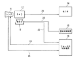
図1は、本発明の実施形態に係る監視テレビカメラシステムの全体構成を示す構成図である。
同図において、本実施形態の監視テレビカメラシステムは、フォーカス制御が可能なレンズ11(ズームレンズ)と、レンズ11に接続されたカメラ12(監視カメラ本体)と、制御可能な旋回台13と、カメラ12の撮像を映像表示するモニタ14と、カメラ12、旋回台13、及びレンズ11を遠隔制御する遠隔制御装置15(遠隔制御手段)と、レンズ11のフォーカスを制御するフォーカス制御装置16(フォーカス制御手段)と、を備える。
なお、符号21〜25は、信号の伝送路を示す。
DESCRIPTION OF THE PREFERRED EMBODIMENTS Embodiments of an automatic focus adjustment device for a surveillance television camera and an automatic focus adjustment method for a surveillance television camera according to the present invention will be described below in detail with reference to the drawings.
FIG. 1 is a configuration diagram showing the overall configuration of a surveillance television camera system according to an embodiment of the present invention.
In the figure, the surveillance television camera system of the present embodiment includes a lens 11 (zoom lens) capable of focus control, a camera 12 (surveillance camera body) connected to the
以下では、本実施形態の監視テレビカメラシステムの機能を説明する。
カメラ12には、外部から制御可能な旋回台13とレンズ11が接続されており、カメラ12の出力映像信号は伝送路21を経て、モニタ14に映像表示される。
一方、カメラ12、旋回台13、レンズ11は、遠隔制御装置15により伝送路22を介して遠隔制御される。これにより、随時かつ的確に、必要な方向に向けて、レンズ11のフォーカスの定まったカメラ12の位置を定めることが可能となり、必要な監視をモニタ14を介して視認することが可能となる。
Below, the function of the surveillance television camera system of this embodiment is demonstrated.
The
On the other hand, the
フォーカス制御装置16には、カメラの旋回角、仰角の一定角度毎にレンズ11の適切なフォーカス制御値を記憶させるデータベースが予め構築されている。また、フォーカス制御装置16は、旋回台13からのカメラ12の旋回角、仰角のデータを伝送路23を介して受信すると共に、伝送路24を介してレンズ11のフォーカス駆動機構を制御できるように構成されている。なお、レンズ11の向きはカメラ12の動きに連動するように構成されている。さらに、フォーカス制御装置16は、伝送路25を介してレンズ12のフォーカス制御値のデータを受信する。
In the
ここで、前記データベースは、特に距離や設置場所の条件を数値で測定しなくても、カメラ12の設置後、実際の映像を見ながら調整することで容易に作成することができる。即ち、カメラ12の設置後、例えば、カメラ12を一定間隔で旋回角、仰角を変化させた後、フォーカス調整を行い、その制御値をメモリに記憶することで容易に作成することができる。
前記データベースは、当初は分解能を粗く設定しておき(例えば、仰角90度を10度分割程度、即ち、上下方向に9等分の角度でオートフォーカス設定をすることで全データベースが入力されるようにしておき)、その後の運用で更に細かな地点でフォーカスを取り直した場合に、データベースを順次細かくして設定することが可能である。
さらに、前記データベースは、一定期間は保存されるように構成することも可能である。また、レンズ11(ズームレンズ)の焦点距離が大きい場合、及びF値が小さい場合には、焦点深度の関係から、前記データベースには、ズームレンズの焦点距離及びレンズのF値の両方若しくはいずれか片方だけを記録しておき、フォーカス調整は、新たに、オートフォーカスを取り直したときに、それまでの記憶値より、焦点距離が大きい状態のときにのみ、若しくはF値が小さい状態のときにのみ、前記データベースのデータを書き換えるように構成することができる。
Here, the database can be easily created by adjusting an actual video image after the
The database is initially set with a coarse resolution (for example, the entire database is input by setting the autofocus at an angle of about 9 degrees in the vertical direction, that is, the elevation angle of 90 degrees is divided into 10 degrees). In the subsequent operation, when the focus is re-established at a finer point, it is possible to sequentially set the database in detail.
Further, the database can be configured to be stored for a certain period of time. Further, when the focal length of the lens 11 (zoom lens) is large and when the F value is small, the focal length of the zoom lens and / or the F value of the lens are stored in the database from the relationship of the focal depth. Only one of them is recorded, and focus adjustment is performed only when the autofocus is newly reset, only when the focal length is larger than the previous stored value, or when the F value is small. The database data can be rewritten.
このように構成することにより、カメラ12が向いている方向の被写体に対して、フォーカスを合わせたフォーカス制御値でもって、予めデータベースを作成しておき、旋回台13から伝送路13を介して通知されたカメラ12の方向に対応するフォーカス制御値を、前記データベースから得ると共に、伝送路24を介して該フォーカス制御値でもってレンズ11のフォーカス駆動機構を制御できるので、カメラ方向に応じた最適なフォーカス状態が常に得られるようになる。
With this configuration, a database is created in advance with a focus control value for focusing on a subject in the direction in which the
伝送路21〜25で伝送される信号は、デジタルデータ化してIPネットワーク等を含む通信ネットワークで伝送することも可能であり、この場合も同様の効果が得られる。
この実施の形態によれば、前述のとおり、カメラ12の旋回角、仰角の一定角度毎にレンズ11のフォーカス制御値を記憶させるデータベースを予め構築しておき、カメラ12を旋回させた場合には、該データベースを参照することで、カメラ12の旋回角、仰角に応じてレンズフォーカスが常に適正となるように調整するので、任意の方向で撮影されている被写体に対して、常に適切にフォーカスを合わせることが可能となる効果が有る。
Signals transmitted through the
According to this embodiment, as described above, when a database for storing the focus control value of the
また、前記データベースの作成は、カメラ12を一定間隔で旋回角、仰角を変化させた後、フォーカス調整を行い、その制御値をメモリに記憶できるようにすることで、カメラを設置後、特に距離や設置場所の条件を数値で測定しなくても、実際の映像を見ながら調整することで可能となる効果がある。
The database is created by changing the turning angle and elevation angle of the
(他の実施の形態)
本発明の監視テレビカメラシステムと、従来から使用されている都度駆動の自動フォーカス調整装置等とを組み合わせることにより、フォーカス制御値を記憶する前記データベースのデータ拡充が容易になり、いわゆる学習効果を有する自動フォーカス調整装置が実現できることは明らかである。
(Other embodiments)
By combining the surveillance TV camera system of the present invention with a conventional automatic focus adjustment device that is driven each time, the database for storing focus control values can be easily expanded, and a so-called learning effect is achieved. Obviously, an automatic focus adjustment device can be realized.
また、前記データベースに、未だ実際の正しいフォーカス制御値が入力されていない方向については、特に、フォーカス制御を行わず、これまでに撮影した地点の条件のままでフォーカスを固定するか、若しくは、2点間の制御値からの補間値を自動入力させる等の既成技術の手段と組み合わせて使用することにより、運用性の優れたシステムが構築できることは明らかでる。 For the direction in which the actual correct focus control value has not yet been input to the database, in particular, focus control is not performed, and the focus is fixed with the conditions of the points photographed so far, or 2 It is clear that a system with excellent operability can be constructed by using in combination with means of existing technology such as automatically inputting an interpolated value from a control value between points.
本発明は、監視テレビカメラシステムの構築に適用可能であり、特に、監視対象の向きに関わらず、常に最良の状態で監視機能が達成できる自動フォーカス調整機能を備えた監視テレビカメラシステムの構築に好適である。 The present invention is applicable to the construction of a surveillance TV camera system, and more particularly to the construction of a surveillance TV camera system having an automatic focus adjustment function that can always achieve the surveillance function in the best state regardless of the orientation of the surveillance target. Is preferred.
11 レンズ(ズームレンズ)
12 カメラ(監視カメラ本体)
13 旋回台
14 モニタ(映像表示装置)
15 遠隔制御装置
16 フォーカス制御装置
21〜25 伝送路
11 Lens (zoom lens)
12 Camera (surveillance camera body)
13
15
Claims (10)
前記ズームレンズに接続された監視カメラ本体と、
前記監視カメラ本体を積載する旋回台と、
前記監視カメラ本体の撮像を映像表示するモニタと、
前記監視カメラ本体と、前記旋回台と、前記ズームレンズとを遠隔制御する遠隔制御手段と、
前記ズームレンズのフォーカスを制御するフォーカス制御手段と、
当初は前記監視カメラ本体の旋回角及び仰角の分解能が粗い一定角度毎に、該角度に対応した前記ズームレンズの適切なフォーカス制御値が設定されているデータベースと、
前記監視カメラ本体の設置後の運用で、前記モニタの実際の映像を視認しながら更に細かな地点でフォーカスが取り直された場合における、前記監視カメラ本体の旋回角及び仰角の分解能が細かい角度に対応するフォーカス制御値でもって、前記データベースの設定を書き換えるデータベース作成手段と、
前記旋回台から通知された前記監視カメラ本体の方向に対応するフォーカス制御値を、前記データベースを参照して取得するフォーカス制御値取得手段と、
前記データベースを参照して取得した前記フォーカス制御値に基づいて、前記ズームレンズのフォーカスを制御するフォーカス制御手段と
を備え、
前記フォーカス制御手段は、前記データベースにフォーカス制御値が入力されていない方向については、前記ズームレンズのフォーカス制御を行うことなく、これまでに撮影した地点の条件のままで前記ズームレンズのフォーカスを固定する
ことを特徴とする監視テレビカメラシステム。 A zoom lens with focus control,
A surveillance camera body connected to the zoom lens;
A swivel for loading the surveillance camera body;
A monitor for displaying an image of the imaging of the surveillance camera body;
Remote control means for remotely controlling the surveillance camera body, the swivel base, and the zoom lens;
Focus control means for controlling the focus of the zoom lens;
Initially, a database in which an appropriate focus control value of the zoom lens corresponding to the angle is set for each fixed angle where the resolution of the turning angle and the elevation angle of the surveillance camera body is rough ,
In the operation after the installation of the surveillance camera body, the resolution of the turning angle and the elevation angle of the surveillance camera body is reduced to a fine angle when the focus is read again at a finer point while visually recognizing the actual image of the monitor. Database creation means for rewriting the database settings with corresponding focus control values;
Focus control value acquisition means for acquiring a focus control value corresponding to the direction of the monitoring camera body notified from the swivel base with reference to the database;
A focus control means for controlling the focus of the zoom lens based on the focus control value acquired by referring to the database ;
The focus control means fixes the focus of the zoom lens in the direction in which the focus control value is not input to the database, without performing the focus control of the zoom lens, without changing the focus of the shooting point. surveillance TV camera system which is characterized in that.
ことを特徴とする請求項1に記載の監視テレビカメラシステム。 The resolution of the database is initially set so as to divide the elevation angle by a predetermined angle, and then autofocus is set at equal angles in the up and down and / or left and right directions. The surveillance television camera system according to claim 1, wherein all data of the camera is input.
ことを特徴とする請求項1又は2に記載の監視テレビカメラシステム。 In the database, if the focal length of the zoom lens is large, and when the F value of the zoom lens is small, only both or either one of the F value of the focal length and the zoom lens of the zoom lens is recorded Then, when the autofocus is taken again thereafter, the corresponding data in the database is rewritten only when the focal length is larger than the stored value or when the F value is small. The surveillance television camera system according to claim 1 or 2 .
ことを特徴とする請求項1から3のいずれか一項に記載の監視テレビカメラシステム。 The surveillance TV camera system according to any one of claims 1 to 3, wherein the swivel base is controlled by the remote control unit via a communication path including an Internet network.
ことを特徴とする請求項1から4のいずれか一項に記載の監視テレビカメラシステム。 The surveillance television camera system according to any one of claims 1 to 4, wherein the zoom lens is controlled by the remote control unit via a communication path including an Internet network.
ことを特徴とする請求項1から5のいずれか一項に記載の監視テレビカメラシステム。 The surveillance television camera system according to any one of claims 1 to 5, wherein the database is installed in the focus control means.
ことを特徴とする請求項1から6のいずれか一項に記載の監視テレビカメラシステム。 The surveillance TV camera system according to any one of claims 1 to 6, wherein the database is created by combining with an automatic focus adjustment device of an existing technology.
ことを特徴とする請求項1から7のいずれか一項に記載の監視テレビカメラシステム。 The surveillance database camera system according to any one of claims 1 to 7, wherein the database is created by using a numerical interpolation technique of an existing technology.
ことを特徴とする請求項1から8のいずれか一項に記載の監視テレビカメラシステム。 The surveillance TV camera system according to any one of claims 1 to 8, wherein the database is configured to be stored for a certain period of time.
前記ズームレンズのフォーカスを制御するフォーカス制御ステップと、
前記監視カメラ本体の設置後の運用で、前記監視カメラ本体の撮像を映像表示するモニタの実際の映像を視認しながら更に細かな地点でフォーカスが取り直された場合における、前記監視カメラ本体の旋回角及び仰角の分解能が細かい角度に対応するフォーカス制御値でもって、当初は前記監視カメラ本体の旋回角及び仰角の分解能が粗い一定角度毎に、該角度に対応した前記ズームレンズの適切なフォーカス制御値が設定されているデータベースの設定を書き換えるデータベース作成ステップと、
前記旋回台から通知された前記監視カメラ本体の方向に対応するフォーカス制御値を、前記データベースを参照して取得するフォーカス制御値取得ステップと、
前記データベースを参照して取得した前記フォーカス制御値に基づいて、前記ズームレンズのフォーカスを制御するフォーカス制御ステップと
を備え、
前記フォーカス制御ステップにおいては、前記データベースにフォーカス制御値が入力されていない方向については、前記ズームレンズのフォーカス制御を行うことなく、これまでに撮影した地点の条件のままで前記ズームレンズのフォーカスを固定する
ことを特徴とする監視テレビカメラの制御方法。 A surveillance camera body connected to a zoom lens capable of focus control, a swivel on which the surveillance camera body is mounted , and a remote control step for remotely controlling the zoom lens;
A focus control step for controlling the focus of the zoom lens;
In operation after the installation of the surveillance camera body, the surveillance camera body turns when the focus is reset at a finer point while visually recognizing the actual image of the monitor displaying the image of the surveillance camera body. With the focus control value corresponding to a fine angle and resolution of the angle of elevation, the focus control value of the zoom lens corresponding to the angle is initially set for each fixed angle where the resolution of the turning angle and the elevation angle of the surveillance camera body is initially coarse. A database creation step to rewrite the settings of the database for which the value is set ;
A focus control value acquisition step of acquiring a focus control value corresponding to the direction of the monitoring camera body notified from the swivel base with reference to the database;
A focus control step for controlling the focus of the zoom lens based on the focus control value acquired with reference to the database , and
In the focus control step, in the direction in which no focus control value is input to the database, the zoom lens is focused without changing the focus control of the zoom lens without changing the focus control of the zoom lens. A method of controlling a surveillance television camera, characterized by being fixed .
Priority Applications (1)
| Application Number | Priority Date | Filing Date | Title |
|---|---|---|---|
| JP2009250353A JP5083293B2 (en) | 2009-10-05 | 2009-10-30 | Surveillance television camera system and surveillance television camera control method |
Applications Claiming Priority (3)
| Application Number | Priority Date | Filing Date | Title |
|---|---|---|---|
| JP2009231730 | 2009-10-05 | ||
| JP2009231730 | 2009-10-05 | ||
| JP2009250353A JP5083293B2 (en) | 2009-10-05 | 2009-10-30 | Surveillance television camera system and surveillance television camera control method |
Publications (2)
| Publication Number | Publication Date |
|---|---|
| JP2011101070A JP2011101070A (en) | 2011-05-19 |
| JP5083293B2 true JP5083293B2 (en) | 2012-11-28 |
Family
ID=44191921
Family Applications (1)
| Application Number | Title | Priority Date | Filing Date |
|---|---|---|---|
| JP2009250353A Active JP5083293B2 (en) | 2009-10-05 | 2009-10-30 | Surveillance television camera system and surveillance television camera control method |
Country Status (1)
| Country | Link |
|---|---|
| JP (1) | JP5083293B2 (en) |
Families Citing this family (2)
| Publication number | Priority date | Publication date | Assignee | Title |
|---|---|---|---|---|
| JP2018152799A (en) | 2017-03-14 | 2018-09-27 | 株式会社リコー | Image processing device, image processing method and program, and image transmission and reception system |
| JP2019082375A (en) * | 2017-10-30 | 2019-05-30 | 株式会社東芝 | Camera device and distance measuring method |
Family Cites Families (7)
| Publication number | Priority date | Publication date | Assignee | Title |
|---|---|---|---|---|
| JPH09205573A (en) * | 1996-01-24 | 1997-08-05 | Fuji Photo Optical Co Ltd | Camera equipment control method |
| JP3780045B2 (en) * | 1996-11-26 | 2006-05-31 | キヤノン株式会社 | Camera control system and control method of camera control system |
| JP3580342B2 (en) * | 1997-09-25 | 2004-10-20 | 横河電機株式会社 | Pan-tilt camera device |
| JP2003051980A (en) * | 2001-08-08 | 2003-02-21 | Matsushita Electric Ind Co Ltd | Automatic focus device, imaging device and camera system |
| JP4164327B2 (en) * | 2002-10-03 | 2008-10-15 | キヤノン株式会社 | Imaging device |
| JP2008191391A (en) * | 2007-02-05 | 2008-08-21 | Nikon Corp | Focusing mechanism, and camera |
| JP2008300950A (en) * | 2007-05-29 | 2008-12-11 | Fujifilm Corp | Photographing apparatus |
-
2009
- 2009-10-30 JP JP2009250353A patent/JP5083293B2/en active Active
Also Published As
| Publication number | Publication date |
|---|---|
| JP2011101070A (en) | 2011-05-19 |
Similar Documents
| Publication | Publication Date | Title |
|---|---|---|
| JP4332231B2 (en) | Imaging device controller and imaging system | |
| US20060209186A1 (en) | Field angle adjustment apparatus, camera system, and field angle adjustment method | |
| US20040179100A1 (en) | Imaging device and a monitoring system | |
| US11190698B2 (en) | Imaging apparatus, control method for imaging apparatus, information processing apparatus, and storage medium | |
| CN102461153A (en) | Control device, camera system, and program | |
| JP6380787B2 (en) | IMAGING DEVICE, CAMERA, DISPLAY DEVICE, IMAGING METHOD, DISPLAY METHOD, AND PROGRAM | |
| JP2021078124A (en) | Intelligent imaging system imaging control method, device, storage medium, and system | |
| JP5083293B2 (en) | Surveillance television camera system and surveillance television camera control method | |
| JP4566908B2 (en) | Imaging system | |
| JP2009200697A (en) | Image transmitter, field angle control method, image receiver, image display system, and image display method | |
| JP5861420B2 (en) | Electronic camera | |
| JP2014027587A (en) | Imaging device, evaluation frame setting system, and control method for imaging device | |
| JP4148251B2 (en) | Imaging device and display device | |
| JP4332580B2 (en) | Control device, control method, and monitoring system | |
| JP2005354748A (en) | Apparatus and method for controlling imaging means | |
| US20060256202A1 (en) | Method and devicefor recording video data | |
| KR20050062859A (en) | Method for positioning a monitoring camera | |
| JP2005348448A (en) | Panorama imaging apparatus | |
| JP2005348449A5 (en) | ||
| KR101194342B1 (en) | Varifocal lens with mega-pixel auto-focus zoom cctv camera for high resolution video abbreviation for charge coupled and its auto-focus control method | |
| KR100988563B1 (en) | Pan tilter and pan tilt control method | |
| KR101454601B1 (en) | Video Phone Having Digital Tilt Function | |
| JP5100563B2 (en) | Surveillance camera device | |
| JP5115018B2 (en) | Monitoring system | |
| JP2010055581A (en) | Process management device and process management method |
Legal Events
| Date | Code | Title | Description |
|---|---|---|---|
| A621 | Written request for application examination |
Free format text: JAPANESE INTERMEDIATE CODE: A621 Effective date: 20110516 |
|
| A977 | Report on retrieval |
Free format text: JAPANESE INTERMEDIATE CODE: A971007 Effective date: 20120425 |
|
| A131 | Notification of reasons for refusal |
Free format text: JAPANESE INTERMEDIATE CODE: A131 Effective date: 20120508 |
|
| A521 | Request for written amendment filed |
Free format text: JAPANESE INTERMEDIATE CODE: A523 Effective date: 20120522 |
|
| TRDD | Decision of grant or rejection written | ||
| A01 | Written decision to grant a patent or to grant a registration (utility model) |
Free format text: JAPANESE INTERMEDIATE CODE: A01 Effective date: 20120807 |
|
| A01 | Written decision to grant a patent or to grant a registration (utility model) |
Free format text: JAPANESE INTERMEDIATE CODE: A01 |
|
| A61 | First payment of annual fees (during grant procedure) |
Free format text: JAPANESE INTERMEDIATE CODE: A61 Effective date: 20120820 |
|
| R150 | Certificate of patent or registration of utility model |
Ref document number: 5083293 Country of ref document: JP Free format text: JAPANESE INTERMEDIATE CODE: R150 Free format text: JAPANESE INTERMEDIATE CODE: R150 |
|
| FPAY | Renewal fee payment (event date is renewal date of database) |
Free format text: PAYMENT UNTIL: 20150914 Year of fee payment: 3 |