JP4979468B2 - Electric vacuum cleaner - Google Patents
Electric vacuum cleaner Download PDFInfo
- Publication number
- JP4979468B2 JP4979468B2 JP2007149146A JP2007149146A JP4979468B2 JP 4979468 B2 JP4979468 B2 JP 4979468B2 JP 2007149146 A JP2007149146 A JP 2007149146A JP 2007149146 A JP2007149146 A JP 2007149146A JP 4979468 B2 JP4979468 B2 JP 4979468B2
- Authority
- JP
- Japan
- Prior art keywords
- dust
- filter
- unit
- amount
- air volume
- Prior art date
- Legal status (The legal status is an assumption and is not a legal conclusion. Google has not performed a legal analysis and makes no representation as to the accuracy of the status listed.)
- Expired - Fee Related
Links
Images


Description
本発明は電気掃除機に関する。 The present invention relates to a vacuum cleaner.
従来、電気掃除機としては、集塵室内のごみ量が所定量を越えたことを使用者に報知して、ダストカップ内のごみを捨てるように使用者に促すものがある。 Conventionally, there are vacuum cleaners that notify the user that the amount of dust in the dust collection chamber has exceeded a predetermined amount and prompt the user to discard the dust in the dust cup.
特開2002−143060号公報(特許文献1)の電気掃除機は、電動送風機と、この電動送風機の稼働により吸い込んだごみを溜める集塵室と、この集塵室内の空気を吸い込む電動送風機と、集塵室を出て電動送風機へ向かう空気が通過するフィルタと、集塵室内のごみ量を検知するセンサとを備えている。このセンサは、集塵室内に向けて光を出射する発光部と、この発光部から出射されて集塵室内を通った光を受光する受光部とを有して、受光部の受光量の変化に基づいて集塵室内のゴミ量を検知する。 An electric vacuum cleaner disclosed in Japanese Patent Application Laid-Open No. 2002-143060 (Patent Document 1) includes an electric blower, a dust collection chamber that collects dust sucked by operation of the electric blower, an electric blower that sucks air in the dust collection chamber, The filter which the air which leaves a dust collection chamber and goes to an electric blower passes, and the sensor which detects the amount of dust in a dust collection chamber are provided. This sensor has a light emitting part that emits light toward the dust collecting chamber and a light receiving part that receives light emitted from the light emitting part and passed through the dust collecting chamber, and changes in the amount of light received by the light receiving part. Based on this, the amount of dust in the dust chamber is detected.
また、特開2000−262449号公報(特許文献2)の電気掃除機は、集塵室に流入するごみを検知するセンサを備え、このセンサの検知結果に基づいて、集塵室に流入したごみの量を積算している。 Moreover, the vacuum cleaner of Unexamined-Japanese-Patent No. 2000-262449 (patent document 2) is equipped with the sensor which detects the dust which flows into a dust collection chamber, Based on the detection result of this sensor, the waste which flowed into the dust collection chamber The amount is accumulated.
しかしながら、上記特許文献1,2の電気掃除機は、集塵室内のごみ量を検知することはできるが、集塵室を出て電動送風機へ向かう空気が通過するフィルタの目詰まりを検知することはできないという問題がある。
そこで、本発明の課題は、集塵室を出て電動送風機へ向かう空気が通過するフィルタの目詰まりを検知することができる電気掃除機を提供することにある。 Then, the subject of this invention is providing the vacuum cleaner which can detect the clogging of the filter through which the air which leaves a dust collection chamber and goes to an electric blower passes.
上記課題を解決するため、本発明の電気掃除機は、
電動送風機と、
上記電動送風機の稼働により吸い込んだごみを溜める集塵室と、
上記集塵室を出て上記電動送風機へ向かう空気が通過するフィルタと、
上記集塵室内に溜まったごみの量を検知するごみ量検知部と、
上記電動送風機の電流の変化に基づいて、上記電動送風機の風量を検知する風量検知部と、
上記ごみ量検知部による検知結果が所定のごみ量以下であることを示し、かつ、上記風量検知部による検知結果が所定の小風量以下であること示した場合、上記フィルタに目詰まりが生じていると判定するフィルタ目詰まり判定部と、
上記ごみ量検知部による検知結果が所定のごみ満杯量であることを示し、かつ、上記風量検知部による検知結果が、上記所定の小風量よりも大きい所定の大風量以上であることを示した場合、上記電動送風機の風量を増加させて、上記集塵室内のごみを圧縮するごみ圧縮部と
を備えたことを特徴としている。
In order to solve the above problems, the vacuum cleaner of the present invention is
An electric blower,
A dust collection chamber for collecting garbage sucked by the operation of the electric blower,
A filter through which air exiting the dust collection chamber and going to the electric blower passes,
A dust amount detection unit for detecting the amount of dust accumulated in the dust collection chamber;
Based on the change in the current of the electric blower, an air volume detection unit that detects the air volume of the electric blower,
When the detection result by the dust amount detection unit indicates that the detection result is less than a predetermined dust amount and the detection result by the air flow detection unit indicates that the detection result is less than a predetermined small air amount, the filter is clogged. A filter clogging determination unit that determines that the
The detection result by the dust amount detection unit indicates a predetermined amount of full garbage, and the detection result by the air amount detection unit indicates that the detection result is equal to or greater than a predetermined large air volume that is greater than the predetermined small air volume. In this case, the electric blower includes a dust compression unit that increases the air volume of the electric blower and compresses the dust in the dust collection chamber .
上記構成の電気掃除機によれば、上記フィルタ目詰まり判定部は、ごみ量検知部による検知結果が所定のごみ量以下であることを示し、かつ、風量検知部による検知結果が所定の小風量以下であること示した場合、フィルタに目詰まりが生じていると判定するので、フィルタの目詰まりを検知できる。 According to the vacuum cleaner having the above configuration, the filter clogging determination unit indicates that the detection result by the dust amount detection unit is equal to or less than a predetermined dust amount, and the detection result by the air volume detection unit is a predetermined small air volume. When it is shown that the following is true, it is determined that the filter is clogged, so that the filter can be detected.
また、上記フィルタ目詰まり判定部がフィルタに目詰まりが生じていると判定した場合、例えば、電動送風機を停止させることにより、フィルタに目詰まりが生じた状態で掃除が行われるのを防ぐことができる。 Further, when the filter clogging determination unit determines that the filter is clogged, for example, by stopping the electric blower, it is possible to prevent the filter from being cleaned in a clogged state. it can.
また、上記ごみ量検知部が集塵室内のごみ量を検知するので、電動送風機の風量の低下が、集塵室内のごみが満杯になったことによるものか、フィルタの目詰まりによるものかも、判別することができる。
また、上記ごみ量検知部による検知結果が所定のごみ満杯量であることを示し、かつ、上記風量検知部による検知結果が、上記所定の小風量よりも大きい所定の大風量以上であることを示した場合、ごみ圧縮部が、電動送風機の風量を増加させて、集塵室内のごみを圧縮するので、ごみ捨て周期を長くすることできる。
したがって、使用者は集塵室内のごみを頻繁に捨てなくてもよいので、使用感を高めることができる。
In addition, since the dust amount detection unit detects the amount of dust in the dust collection chamber, the decrease in the air flow of the electric blower may be due to the dust in the dust collection chamber becoming full, or due to clogging of the filter, Can be determined.
In addition, the detection result by the dust amount detection unit indicates that the predetermined amount is full, and the detection result by the air amount detection unit is equal to or greater than a predetermined large air volume that is greater than the predetermined small air volume. In the case shown, the dust compressing section increases the air volume of the electric blower and compresses the dust in the dust collecting chamber, so that the waste disposal cycle can be lengthened.
Therefore, the user does not have to frequently throw away the dust in the dust collection chamber, so that the feeling of use can be enhanced.
一実施形態の電気掃除機は、
上記フィルタ目詰まり判定部が上記フィルタに目詰まりが生じていると判定した場合、上記フィルタに目詰まりが生じていることを使用者に報知するフィルタ目詰まり報知部を備える。
The vacuum cleaner of one embodiment
If the filter clogging determining unit determines that the clogging in the filter occurs, Ru includes a filter clogging notifying unit for notifying the user that the clogging occurs in the filter.
上記実施形態の電気掃除機によれば、上記フィルタ目詰まり判定部が上記フィルタに目詰まりが生じていると判定した場合、フィルタ目詰まり報知部がフィルタの目詰まりを使用者に報知するので、使用者はフィルタの目詰まりを容易かつ確実に認識することができる。 According to the vacuum cleaner of the above embodiment, when the filter clogging determination unit determines that the filter is clogged, the filter clogging notification unit notifies the user of clogging of the filter. The user can easily and reliably recognize the clogging of the filter.
一実施形態の電気掃除機は、
上記フィルタを自動で清掃するフィルタ自動清掃部と、
上記フィルタ自動清掃部の運転を制御する制御部と
を備え、
上記ごみ量検知部による検知結果が上記所定のごみ量以下であることを示し、かつ、上記風量検知部による検知結果が上記所定の大風量未満であることを示した場合、上記制御部は、上記フィルタ自動清掃部に上記フィルタの清掃を所定時間行わせ、
上記ごみ量検知部による検知結果が上記所定のごみ量以下であることを示し、かつ、上記風量検知部による検知結果が、上記所定の小風量よりも大きい所定の大風量以上であることを示した場合、上記制御部は、上記フィルタ自動清掃部が上記フィルタを清掃するのを禁止する。
The vacuum cleaner of one embodiment
A filter automatic cleaning section for automatically cleaning the filter;
A control unit for controlling the operation of the filter automatic cleaning unit,
When the detection result by the dust amount detection unit indicates that it is equal to or less than the predetermined dust amount and the detection result by the air amount detection unit indicates that the detection result is less than the predetermined large air volume, the control unit Let the filter automatic cleaning unit perform the cleaning of the filter for a predetermined time,
Indicates that the detection result by the dust amount detection unit is equal to or less than the predetermined dust amount, and that the detection result by the air volume detection unit is equal to or greater than a predetermined large air volume that is greater than the predetermined small air volume. In this case, the control unit prohibits the automatic filter cleaning unit from cleaning the filter.
上記実施形態の電気掃除機によれば、上記ごみ量検知部による検知結果が所定のごみ量以下であることを示し、かつ、風量検知部による検知結果が、所定の小風量よりも大きい所定の大風量以上であることを示した場合、フィルタに目詰まり発生していない。 According to the vacuum cleaner of the said embodiment, it shows that the detection result by the said dust amount detection part is below a predetermined dust amount, and the detection result by an air volume detection part is larger than predetermined | prescribed small air volume. If it indicates that the air volume is greater than the air volume, the filter is not clogged.
したがって、その場合において、制御部がフィルタ自動清掃部にフィルタの清掃を行わせないので、フィルタ自動清掃部が無駄に稼働しない。 Therefore, in that case, since the control unit does not cause the filter automatic cleaning unit to clean the filter, the filter automatic cleaning unit does not operate wastefully.
その結果、上記フィルタ自動清掃部の部品の寿命を延ばすことができ、かつ、省エネ効果が得られる。 As a result, the lifetime of the parts of the automatic filter cleaning unit can be extended, and an energy saving effect can be obtained.
また、上記ごみ量検知部による検知結果が所定のごみ量以下であることを示し、かつ、風量検知部による検知結果が、所定の小風量よりも大きい所定の大風量未満であることを示した場合、フィルタに目詰まりが生じ始めている。 Further , the detection result by the dust amount detection unit indicates that it is less than or equal to a predetermined dust amount, and the detection result by the air volume detection unit indicates that the detection result is less than a predetermined large air volume that is larger than a predetermined small air volume. In this case, the filter is starting to become clogged.
したがって、その場合において、制御部がフィルタ自動清掃部にフィルタの清掃を所定時間行わせるので、フィルタの目詰まりが早い段階で解消されるので、効率のよい清掃をフィルタに行うことができる。 Therefore, in this case, the control unit causes the filter automatic cleaning unit to clean the filter for a predetermined time, so that the filter clogging is eliminated at an early stage, so that efficient cleaning can be performed on the filter.
一実施形態の電気掃除機では、
上記ごみ量検知部による検知結果が上記所定のごみ量以下であることを示し、かつ、上記風量検知部による検知結果が上記所定の小風量以下である場合、上記制御部は、上記フィルタ自動清掃部に上記フィルタの清掃を上記所定時間より長い時間行わせる。
In the vacuum cleaner of one embodiment,
When the detection result by the dust amount detection unit indicates that the detection result is equal to or less than the predetermined dust amount and the detection result by the air amount detection unit is equal to or less than the predetermined small air amount, the control unit performs the automatic filter cleaning. Causing the filter to clean the filter for a time longer than the predetermined time.
上記実施形態の電気掃除機によれば、上記ごみ量検知部による検知結果が所定のごみ量以下であることを示し、かつ、風量検知部による検知結果が所定の小風量以下である場合、フィルタが目詰まりしている。 According to the vacuum cleaner of the above embodiment, when the detection result by the dust amount detection unit indicates that it is less than or equal to a predetermined dust amount, and the detection result by the air volume detection unit is less than or equal to a predetermined small amount of air, the filter Is clogged.
したがって、その場合において、制御部がフィルタ自動清掃部にフィルタの清掃を所定時間より長い時間行わせるので、フィルタの目詰まりを確実に解消することができる。 Therefore, in this case, the control unit causes the filter automatic cleaning unit to clean the filter for a time longer than the predetermined time, so that the filter clogging can be reliably eliminated.
一実施形態の電気掃除機は、
上記ごみ量検知部による検知結果が上記所定のごみ量以上であることを示し、かつ、上記風量検知部による検知結果が上記所定の小風量以上である場合、上記集塵室内のごみを捨てるように使用者に促すごみ捨て報知部を備えた。
The vacuum cleaner of one embodiment
When the detection result by the dust volume detection unit indicates that the dust volume is equal to or greater than the predetermined dust volume and the detection result by the air volume detection unit is equal to or greater than the predetermined small wind volume, the dust in the dust collection chamber is discarded. In addition, a garbage disposal notifying section for prompting the user is provided.
上記実施形態の電気掃除機によれば、上記ごみ量検知部による検知結果が所定のごみ量以上であることを示し、かつ、風量検知部による検知結果が所定の小風量以上である場合、フィルタは目詰まりしていないが、集塵室内のごみは捨てる必要がある。 According to the vacuum cleaner of the above-described embodiment, when the detection result by the dust amount detection unit indicates a predetermined dust amount or more and the detection result by the air amount detection unit is a predetermined small air amount or more, the filter Is not clogged, but the dust in the dust chamber must be discarded.
したがって、その場合において、上記ごみ捨て報知部が集塵室内のごみを捨てるように使用者に促すので、捨てる必要があるごみが集塵室内に放置されるのを防ぐことができる。 Therefore, in this case, the garbage disposal notification unit prompts the user to discard the garbage in the dust collection chamber, so that it is possible to prevent the waste that needs to be discarded from being left in the dust collection chamber.
また、上記ごみ捨て報知部による報知があった場合、使用者はフィルタを直接見たりしなくても、フィルタの清掃が不要であると判る。 In addition, when there is a notification by the garbage disposal notification unit, it is understood that the user does not need to clean the filter without looking directly at the filter.
したがって、使用者に無駄な確認作業を行わせないようにして、使用感を高めることができる。 Therefore, it is possible to enhance the feeling of use by preventing the user from performing unnecessary confirmation work.
一実施形態の電気掃除機では、
上記ごみ量検知部は、発光部と、上記発光部が出射した光を受光すると共に、その光に応じた信号を出力する受光部とを有し、
上記信号を受けて周波数信号に変換すると共に、この変換した周波数信号を上記ごみ量検知部に出力する信号変換部を備え、
上記ごみ量検知部は、上記信号変換部が出力した上記周波数信号に基づいて、上記集塵室内のごみ量を検知する。
In the vacuum cleaner of one embodiment,
The dust amount detection unit includes a light emitting unit and a light receiving unit that receives light emitted from the light emitting unit and outputs a signal corresponding to the light,
A signal converter that receives the signal and converts it to a frequency signal and outputs the converted frequency signal to the dust amount detector,
The dust amount detection unit detects the amount of dust in the dust collection chamber based on the frequency signal output from the signal conversion unit.
上記実施形態の電気掃除機によれば、上記信号変換部は受光部からの信号を受けて周波数信号に変換するので、周波数信号に基づくことにより、受光部の受光量の変化を正確に判ることができる。 According to the vacuum cleaner of the above embodiment, the signal conversion unit receives a signal from the light receiving unit and converts the signal into a frequency signal. Therefore, based on the frequency signal, the change in the amount of light received by the light receiving unit can be accurately determined. Can do.
したがって、上記ごみ量検知部は、信号変換部が出力した周波数信号に基づいて、集塵室内のごみ量を検知するので、集塵室内のごみ量の検知精度を高めることができる。 Therefore, since the said dust amount detection part detects the dust amount in a dust collection chamber based on the frequency signal which the signal conversion part output, the detection accuracy of the dust amount in a dust collection chamber can be improved.
本発明の電気掃除機によれば、上記フィルタ目詰まり判定部は、ごみ量検知部による検知結果が所定のごみ量以下であることを示し、かつ、風量検知部による検知結果が所定の小風量以下であること示した場合、フィルタに目詰まりが生じていると判定することによって、フィルタの目詰まりを検知できる。 According to the vacuum cleaner of the present invention, the filter clogging determination unit indicates that the detection result by the dust amount detection unit is equal to or less than a predetermined dust amount, and the detection result by the air volume detection unit is a predetermined small air volume. When it is shown that the following is true, it is possible to detect clogging of the filter by determining that the filter is clogged.
以下、本発明の電気掃除機を図示の実施の形態により詳細に説明する。 Hereinafter, the vacuum cleaner of this invention is demonstrated in detail by embodiment of illustration.
図1に、本発明の一実施の形態の電気掃除機の概略斜視図を示す。 In FIG. 1, the schematic perspective view of the vacuum cleaner of one embodiment of this invention is shown.
上記電気掃除機は、掃除機本体1、ホース2、手元側パイプ3、延長管4および吸込口5を備えている。
The vacuum cleaner includes a vacuum cleaner body 1, a
上記掃除機本体1は、掃除機全体を制御する制御部6と、集塵室の一例としてのダストカップ7と、電動送風機8(図2参照)とを有している。
The said vacuum cleaner main body 1 has the control part 6 which controls the whole vacuum cleaner, the
上記手元側パイプ3には、手元スイッチ10を有する把手部9が設けられている。使用者が手元スイッチ6を操作することにより、電動送風機8がONまたはOFFされたり、電動送風機8の吸引ファン(図示せず)が高速回転または低速回転したりする。また、上記電動送風機8がONされると、ゴミが空気と共に吸込口5に吸い込まれ、延長管4、手元側パイプ3およびホース2を順次流れた後、ダストカップ7内に入る。
The
上記吸込口5は、図示しないが、モータと、このモータによって回転駆動するブラシとを有している。このモータのONやOFF等の制御は手元スイッチ6で行える。
Although not shown, the
図2に、上記掃除機本体1の側方から見た模式断面図を示す。 In FIG. 2, the schematic cross section seen from the side of the said cleaner body 1 is shown.
上記掃除機本体1内には、ダストカップ7の後方に電動送風機8が配置されている。また、上記掃除機本体1内には、ダストカップ7の上方に位置するように連絡通路12が設けられている。
An
上記ダストカップ7内では、電動送風機8のON時、空気が高速旋回し、その空気からごみが遠心分離される。上記空気から遠心分離されたごみはダストカップ7内に溜まる。一方、上記ごみが除去された空気は、排気筒11を通ってダストカップ7外に出た後、連絡通路12を流れて電動送風機8へ向かう。
In the
上記ダストカップ7の下流側かつ電動送風機8の上流側にはフィルタ13が配置されている。これにより、上記ダストカップ7で除去できなかった僅かな微細塵をフィルタ13で捕塵することができる。
A
上記フィルタ13を通過した空気は、電動送風機8によって、図示しない排気通路を送られて、掃除機本体1外に出る。
The air that has passed through the
図3に、図2のIII−III線から見た模式断面図を示す。 FIG. 3 shows a schematic cross-sectional view taken along line III-III in FIG.
上記ダストカップ7にはごみ量検知部の一例としてのごみセンサ16が取り付けられている。このごみセンサ16は、発光部14と、この発光部14が出射した光を受光すると共に、その光に応じた信号を出力する受光部15とを有している。この発光部14と受光部15とはダストカップ7を挟むように配置されている。また、上記発光部14から図中矢印方向に出射された光は、ダストカップ7内を通って受光部15に入射する。このため、上記ダストカップ7は、発光部14が出射した光を透過する材料で形成されている。
A
図4に、上記電気掃除機の主要部のブロック図を示す。 In FIG. 4, the block diagram of the principal part of the said vacuum cleaner is shown.
上記制御部6は、制御回路部61、風量検知部62、フィルタ目詰まり判定部64、ごみ圧縮部65および信号変換部66を有する。また、上記制御部6は、発光部14、受光部15、駆動回路部17、表示部18、ブザー部19、電源部20およびフィルタ自動清掃装置21に電気的に接続されて、電源部20から電源が供給されている。なお、上記フィルタ自動清掃装置21はフィルタ自動清掃部の一例である。また、上記表示部18,ブザー部19は、それぞれ、フィルタ目詰まり報知部の一例であり、かつ、ごみ捨て報知部の一例である。
The control unit 6 includes a
上記制御回路部61は、手元スイッチ6からの入力に応じて電動送風機8の制御を行ったり各種情報の処理や表示等の制御を行う。
The
上記駆動回路部17は、制御回路部61の指令に従って電動送風機8をONすると共に、電動送風機8に流れる電流を検出して制御部6へ送出する。
The drive circuit unit 17 turns on the
上記風量検知部62は、電動送風機8に流れる電流の変化に基づいて、電動送風機8の風量を検知する。
The air
上記表示部18は、運転状態を表示したり、異常が発生していることを表示したりして、電動送風機8の状態を使用者に知らせている。
The
上記ブザー部19は、例えば異常時に警報音を発して、電気掃除機に異常が発生していることを使用者に知らせる。
For example, the
上記発光部14はLED(発光ダイオード)等を含んで光を出射する。この光はダストカップ7を通過して受光部15に入射する。そして、上記受光部15は受光した光の強さに応じた信号を制御部6へ送出する。
The
上記信号変換部66は、受光部15からの信号を受けて周波数信号に変換すると共に、この変換した周波数信号をごみセンサ16に出力する。
The
上記ごみセンサ16は、信号変換部66が出力した周波数信号に基づいて、ダストカップ7内のごみ量を検知する。つまり、上記ごみセンサ16は、ダストカップ7内のごみの溜まり具合を検知する。
The
上記フィルタ自動清掃装置21は、図示しないが、振動発生機構を有し、この振動発生機構によってフィルタ13に振動を与えて、フィルタ13に付着した微細塵を落とし、フィルタ13を清掃する。また、上記フィルタ自動清掃装置21は、電動送風機8がOFFされた後、自動的にフィルタ13を清掃する機能を有する。
Although not shown, the automatic
上記フィルタ目詰まり判定部64は、ごみセンサ16による検知結果と、風量検知部62による検知結果とに基づいて、フィルタ13に目詰まりが生じているか否かを判定する。
The filter clogging determination unit 64 determines whether the
上記ごみ圧縮部65は、電動送風機8の風量を増加させて、ダストカップ7内のごみを圧縮する。
The
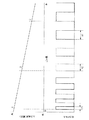
図5に、上記電動送風機8の風量と検知電流(電動送風機8に流れる電流)との関係を示す。
FIG. 5 shows the relationship between the air volume of the
上記フイルタ13にごみが詰まったり、ダストカップ7内にごみが溜まったりすると、ダストカップ7の風量が低下して設定レベル1となる。さらに、上記フイルタ13にごみが詰まったり、ダストカップ7内にごみが溜まったりすると、ダストカップ7の風量がさらに低下して設定レベル2となる。また、上記ダストカップ7の風量の低下に伴って、検知電流も低下する。
When the
上記設定レベル1はフィルタ13の清掃をしなくてもよい風量レベルであり、設定レベル2は風量が低下しフィルタ13の清掃またはごみ捨ての必要な風量レベルである。なお、上記設定レベル1の風量が大風量の一例であり、設定レベル2の風量が小風量の一例である。
The setting level 1 is an air volume level that does not require cleaning of the
更に、上記電動送風機8の風量が低下して設定レベル3に達すると、風量減少による電動送風機8の温度上昇等の不都合を生じる領域に近づくため、表示部18およびブザー部19の少なくとも一方によって使用者に警報を出したり、電動送風機8のパワーを減少させて温度上昇等を防ぐ動作をする。
Further, when the air flow rate of the
図6に、上記受光部15の受光強度と信号変換部66の出力信号の周波数との関係を示す。
FIG. 6 shows the relationship between the received light intensity of the
上記ダストカップ7内に溜まるごみが多くなるにつれて、受光部15の受光量は減少していく。この受光量が多い場合、信号変換部66の出力パルスのパルス幅はt1と小さいが、受光量の減少に伴って、信号変換部66の出力パルスのパルス幅はt2,t3と大きくなる。すなわち、上記受光量の減少に伴って信号変換部66の出力信号の周波数は低くなる。したがって、上記周波数を検知することにより、ダストカップ7内に溜まったごみの量を検知できる。
As the amount of dust accumulated in the
上記構成の電気掃除機によれば、電動送風機8の風量低下は、ダストカップ7内のごみ量が一定量を超えたことによる原因と、フィルタ13の目詰まりによる原因とがある。
According to the vacuum cleaner having the above configuration, the reduction in the air volume of the
より詳しくは、上記ごみセンサ16が検知したごみ量が所定のごみ量以下つまりダストカップ7内のごみ量が少量であり、かつ、風量検知部62が検知した風量の検知レベルが設定レベル2以下(風量減少を検知)の場合は、フィルタ13の目詰まりで風量が低下している判断できる。
More specifically, the amount of dust detected by the
したがって、その場合は、フィルタ目詰まり判定部64はフィルタ13に目詰まりが発生していると判定する。
Therefore, in that case, the filter clogging determination unit 64 determines that the
また、上記フィルタ目詰まり判定部64によって、フィルタ13に目詰まりが発生していると判定されると、表示部18にフィルタ目詰まり表示を行ったり、ブザー部19で警報音を鳴らしたりして、フィルタ13に目詰まりが発生していることを使用者に知らせる。
When the filter clogging determination unit 64 determines that the
したがって、上記フィルタに目詰まりが生じた状態で掃除が行われるのを防ぐことができる。 Therefore, it is possible to prevent the cleaning from being performed in a state where the filter is clogged.
また、上記ごみセンサ16が検知したごみ量が少量であり、かつ、風量検知部62が検知した風量のレベルが設定レベル1以上である場合は、フィルタ13の目詰まりが清掃を必要とするレベルまで汚れていないと判断して、フィルタ自動清掃装置21がフィルタ13の清掃を行わないようにする。
Further, when the amount of dust detected by the
したがって、上記フィルタ自動清掃装置21が無駄に稼働しないので、フィルタ自動清掃装置21の部品の寿命を延ばすことができ、かつ、省エネ効果が得られる。
Therefore, since the automatic
また、上記ごみセンサ16が検知したごみ量が少量であり、かつ、風量検知部62が検知した風量のレベルが設定レベル2を越えているが設定レベル1以下である場合は、フィルタ13の目詰まりが少し進行したと判断できるため、フィルタ自動清掃装置21にフィルタ13の清掃を行わせる。
Further, when the amount of dust detected by the
したがって、上記フィルタ13の目詰まりが早い段階で解消されるので、効率のよい清掃をフィルタ13に行うことができる。
Accordingly, the clogging of the
また、上記ごみセンサ16が検知したごみ量が少量であり、かつ、風量検知部62が検知した風量のレベルが設定レベル2以下である場合は、フィルタ13が目詰まりしていると判断する。そして、上記フィルタ13の目詰まりが少し進行した判断した場合に比べて、フィルタ自動清掃装置21の動作時間を長くして、フィルタ13の目詰まりを確実に解消する。
Further, when the amount of dust detected by the
また、上記ごみセンサ16が検知したごみ量がごみ満杯量であり、かつ、風量検知部62が検知した風量のレベルが設定レベル1以上の場合は、ごみ捨て表示のみ(フィルタ13目詰まり表示なし)または警報を出力する。この機能により、使用者はフィルタ13の清掃までしなくてよいことが一目瞭然で判断できるため、フィルタ13の確認をする必要がない。
Further, when the amount of dust detected by the
また、上記ごみセンサ16が検知したごみ量がごみ満杯量であり、かつ、風量検知部62が検知した風量のレベルが設定レベル1以上の場合は、制御部6は電動送風機8の入力を一定時間のみ増加させて、ダストカップ7内のごみを圧縮させる。
Further, when the amount of dust detected by the
その結果、上記ごみセンサ16が検知したごみ量がごみ満杯量未満になれば、ごみすて表示を出力しない。この機能によりごみ捨て周期を長くできる。
As a result, if the amount of dust detected by the
上記信号変換部66が受光部15からの信号を受けて周波数信号に変換することにより、受光のアナログ変化をより大きな変化量(数十KHz〜数Hz)に変換することができ変化を確実に捉えることができる。
The
上記実施の形態では、発光部14および受光部15を、発光部14が出射した光の光軸がダストカップ7の中心軸を通るように配置していたが、発光部14および受光部15を、発光部14が出射した光の光軸がダストカップ7の中心軸を通らないように配置してもよい。
In the above embodiment, the
本発明は、サイクロン式掃除機のみならず、紙パック式掃除機等に適用することができる。 The present invention can be applied not only to a cyclonic vacuum cleaner but also to a paper pack vacuum cleaner.
例えば、本発明を紙パック式電気掃除機に適用する場合、紙パック内に溜まるごみの量は、紙パック内に流入するごみを検知し、紙パック内に流入したごみの量を積算して求めればよい。 For example, when the present invention is applied to a paper pack type vacuum cleaner, the amount of dust accumulated in the paper pack is detected by detecting the dust flowing into the paper pack and integrating the amount of dust flowing into the paper pack. Find it.
6 制御部
7 ダストカップ
8 電動送風機
13 フィルタ
16 ごみセンサ
18 表示部
19 ブザー部
21 フィルタ自動清掃装置
62 風量検知部
64 フィルタ目詰まり判定部
65 ごみ圧縮部
66 信号変換部
6
Claims (3)
上記電動送風機の稼働により吸い込んだごみを溜める集塵室と、
上記集塵室を出て上記電動送風機へ向かう空気が通過するフィルタと、
上記集塵室内に溜まったごみの量を検知するごみ量検知部と、
上記電動送風機の電流の変化に基づいて、上記電動送風機の風量を検知する風量検知部と、
上記ごみ量検知部による検知結果が所定のごみ量以下であることを示し、かつ、上記風量検知部による検知結果が所定の小風量以下であること示した場合、上記フィルタに目詰まりが生じていると判定するフィルタ目詰まり判定部と、
上記ごみ量検知部による検知結果が所定のごみ満杯量であることを示し、かつ、上記風量検知部による検知結果が、上記所定の小風量よりも大きい所定の大風量以上であることを示した場合、上記電動送風機の風量を増加させて、上記集塵室内のごみを圧縮するごみ圧縮部と
を備えたことを特徴とする電気掃除機。 An electric blower,
A dust collection chamber for collecting garbage sucked by the operation of the electric blower,
A filter through which air exiting the dust collection chamber and going to the electric blower passes,
A dust amount detection unit for detecting the amount of dust accumulated in the dust collection chamber;
Based on the change in the current of the electric blower, an air volume detection unit that detects the air volume of the electric blower,
When the detection result by the dust amount detection unit indicates that the detection result is less than a predetermined dust amount and the detection result by the air flow detection unit indicates that the detection result is less than a predetermined small air amount, the filter is clogged. A filter clogging determination unit that determines that the
The detection result by the dust amount detection unit indicates a predetermined amount of full garbage, and the detection result by the air amount detection unit indicates that the detection result is equal to or greater than a predetermined large air volume that is greater than the predetermined small air volume. In this case, the electric vacuum cleaner includes: a dust compression section that increases the air volume of the electric blower and compresses the dust in the dust collection chamber .
上記フィルタを自動で清掃するフィルタ自動清掃部と、
上記フィルタ自動清掃部の運転を制御する制御部と
を備え、
上記ごみ量検知部による検知結果が上記所定のごみ量以下であることを示し、かつ、上記風量検知部による検知結果が上記所定の大風量未満であることを示した場合、上記制御部は、上記フィルタ自動清掃部に上記フィルタの清掃を所定時間行わせ、
上記ごみ量検知部による検知結果が上記所定のごみ量以下であることを示し、かつ、上記風量検知部による検知結果が、上記所定の小風量よりも大きい所定の大風量以上であることを示した場合、上記制御部は、上記フィルタ自動清掃部が上記フィルタを清掃するのを禁止することを特徴とする電気掃除機。 The vacuum cleaner according to claim 1, wherein
A filter automatic cleaning section for automatically cleaning the filter;
A control unit for controlling the operation of the filter automatic cleaning unit,
When the detection result by the dust amount detection unit indicates that it is equal to or less than the predetermined dust amount and the detection result by the air amount detection unit indicates that the detection result is less than the predetermined large air volume, the control unit Let the filter automatic cleaning unit perform the cleaning of the filter for a predetermined time,
Indicates that the detection result by the dust amount detection unit is equal to or less than the predetermined dust amount, and that the detection result by the air volume detection unit is equal to or greater than a predetermined large air volume that is greater than the predetermined small air volume. In this case, the control unit prohibits the automatic filter cleaning unit from cleaning the filter.
上記ごみ量検知部は、発光部と、上記発光部が出射した光を受光すると共に、その光に応じた信号を出力する受光部とを有し、
上記信号を受けて周波数信号に変換すると共に、この変換した周波数信号を上記ごみ量検知部に出力する信号変換部を備え、
上記ごみ量検知部は、上記信号変換部が出力した上記周波数信号に基づいて、上記集塵室内のごみ量を検知することを特徴とする電気掃除機。 The vacuum cleaner according to claim 1 or 2,
The dust amount detection unit includes a light emitting unit and a light receiving unit that receives light emitted from the light emitting unit and outputs a signal corresponding to the light,
A signal converter that receives the signal and converts it to a frequency signal and outputs the converted frequency signal to the dust amount detector,
The dust amount detection unit detects the amount of dust in the dust collection chamber based on the frequency signal output from the signal conversion unit.
Priority Applications (1)
| Application Number | Priority Date | Filing Date | Title |
|---|---|---|---|
| JP2007149146A JP4979468B2 (en) | 2007-06-05 | 2007-06-05 | Electric vacuum cleaner |
Applications Claiming Priority (1)
| Application Number | Priority Date | Filing Date | Title |
|---|---|---|---|
| JP2007149146A JP4979468B2 (en) | 2007-06-05 | 2007-06-05 | Electric vacuum cleaner |
Publications (3)
| Publication Number | Publication Date |
|---|---|
| JP2008301878A JP2008301878A (en) | 2008-12-18 |
| JP2008301878A5 JP2008301878A5 (en) | 2009-12-03 |
| JP4979468B2 true JP4979468B2 (en) | 2012-07-18 |
Family
ID=40231126
Family Applications (1)
| Application Number | Title | Priority Date | Filing Date |
|---|---|---|---|
| JP2007149146A Expired - Fee Related JP4979468B2 (en) | 2007-06-05 | 2007-06-05 | Electric vacuum cleaner |
Country Status (1)
| Country | Link |
|---|---|
| JP (1) | JP4979468B2 (en) |
Cited By (1)
| Publication number | Priority date | Publication date | Assignee | Title |
|---|---|---|---|---|
| JP2017189479A (en) * | 2016-04-15 | 2017-10-19 | 日立アプライアンス株式会社 | Vacuum cleaner and vacuum cleaner system |
Families Citing this family (9)
| Publication number | Priority date | Publication date | Assignee | Title |
|---|---|---|---|---|
| EP2548489B1 (en) | 2006-05-19 | 2016-03-09 | iRobot Corporation | Removing debris from cleaning robots |
| EP2497403B1 (en) | 2009-11-04 | 2017-01-04 | LG Electronics Inc. | Vacuum cleaner |
| KR101136592B1 (en) | 2009-12-30 | 2012-04-18 | 엘지전자 주식회사 | A structure for sensing clogging for a vacuum cleaner |
| CN105769062A (en) | 2010-12-30 | 2016-07-20 | 美国iRobot公司 | Debris monitoring |
| JP2013128670A (en) * | 2011-12-21 | 2013-07-04 | Toshiba Corp | Vacuum cleaner |
| US9901233B2 (en) | 2013-11-26 | 2018-02-27 | Koninklijke Philips N.V. | Air filter monitoring |
| CN109124481A (en) * | 2018-09-17 | 2019-01-04 | 珠海格力电器股份有限公司 | Dust collection equipment and its control device and method |
| WO2020158880A1 (en) * | 2019-01-31 | 2020-08-06 | シャープ株式会社 | Electric vacuum cleaner |
| CN112168065B (en) * | 2020-09-29 | 2023-04-28 | 追觅创新科技(苏州)有限公司 | Method, device, apparatus and storage medium for determining blockage of air duct in cleaning equipment |
Family Cites Families (3)
| Publication number | Priority date | Publication date | Assignee | Title |
|---|---|---|---|---|
| JPH08166818A (en) * | 1994-12-13 | 1996-06-25 | Matsushita Electric Ind Co Ltd | State recognition device |
| JP2004283344A (en) * | 2003-03-20 | 2004-10-14 | Toshiba Tec Corp | Vacuum cleaner and its operation method |
| JP2007061540A (en) * | 2005-09-02 | 2007-03-15 | Matsushita Electric Ind Co Ltd | Dust collection apparatus |
-
2007
- 2007-06-05 JP JP2007149146A patent/JP4979468B2/en not_active Expired - Fee Related
Cited By (2)
| Publication number | Priority date | Publication date | Assignee | Title |
|---|---|---|---|---|
| JP2017189479A (en) * | 2016-04-15 | 2017-10-19 | 日立アプライアンス株式会社 | Vacuum cleaner and vacuum cleaner system |
| JP7022500B2 (en) | 2016-04-15 | 2022-02-18 | 日立グローバルライフソリューションズ株式会社 | Vacuum cleaner and vacuum cleaner system |
Also Published As
| Publication number | Publication date |
|---|---|
| JP2008301878A (en) | 2008-12-18 |
Similar Documents
| Publication | Publication Date | Title |
|---|---|---|
| JP4979468B2 (en) | Electric vacuum cleaner | |
| JP4315146B2 (en) | Electric vacuum cleaner | |
| JP4654794B2 (en) | Electric vacuum cleaner | |
| JP2007117144A5 (en) | ||
| JP2008301878A5 (en) | ||
| JP2008062017A (en) | Control method of vacuum cleaner | |
| JP4904226B2 (en) | Cyclone dust collector, vacuum cleaner | |
| JP2007143818A (en) | Vacuum cleaner | |
| TWI403300B (en) | Method for controlling cleaning apparatus | |
| JP4736608B2 (en) | Notification device and vacuum cleaner provided with the same | |
| JP4496573B2 (en) | Control circuit for electric blower and vacuum cleaner | |
| JP5920191B2 (en) | Electric vacuum cleaner | |
| WO2020158880A1 (en) | Electric vacuum cleaner | |
| JP4110929B2 (en) | Electric vacuum cleaner | |
| JP5240083B2 (en) | Electric vacuum cleaner | |
| JP4655949B2 (en) | Electric vacuum cleaner | |
| JP5040454B2 (en) | Electric vacuum cleaner | |
| JP5333000B2 (en) | Electric vacuum cleaner | |
| JP2004283217A (en) | Vacuum cleaner | |
| JP4785401B2 (en) | Vacuum cleaner | |
| JP2007275502A (en) | Vacuum cleaner | |
| JP2008264199A (en) | Vacuum cleaner | |
| JP2007167381A (en) | Vacuum cleaner | |
| JP2008000390A (en) | Vacuum cleaner | |
| JP5034574B2 (en) | Electric vacuum cleaner |
Legal Events
| Date | Code | Title | Description |
|---|---|---|---|
| A521 | Written amendment |
Free format text: JAPANESE INTERMEDIATE CODE: A523 Effective date: 20091021 |
|
| A621 | Written request for application examination |
Free format text: JAPANESE INTERMEDIATE CODE: A621 Effective date: 20091021 |
|
| A977 | Report on retrieval |
Free format text: JAPANESE INTERMEDIATE CODE: A971007 Effective date: 20111021 |
|
| A131 | Notification of reasons for refusal |
Free format text: JAPANESE INTERMEDIATE CODE: A131 Effective date: 20111025 |
|
| A521 | Written amendment |
Free format text: JAPANESE INTERMEDIATE CODE: A523 Effective date: 20111220 |
|
| TRDD | Decision of grant or rejection written | ||
| A01 | Written decision to grant a patent or to grant a registration (utility model) |
Free format text: JAPANESE INTERMEDIATE CODE: A01 Effective date: 20120327 |
|
| A01 | Written decision to grant a patent or to grant a registration (utility model) |
Free format text: JAPANESE INTERMEDIATE CODE: A01 |
|
| A61 | First payment of annual fees (during grant procedure) |
Free format text: JAPANESE INTERMEDIATE CODE: A61 Effective date: 20120417 |
|
| FPAY | Renewal fee payment (event date is renewal date of database) |
Free format text: PAYMENT UNTIL: 20150427 Year of fee payment: 3 |
|
| R150 | Certificate of patent or registration of utility model |
Free format text: JAPANESE INTERMEDIATE CODE: R150 |
|
| LAPS | Cancellation because of no payment of annual fees |