JP4735646B2 - Water flow control device and medical injection circuit using the same - Google Patents
Water flow control device and medical injection circuit using the same Download PDFInfo
- Publication number
- JP4735646B2 JP4735646B2 JP2007554881A JP2007554881A JP4735646B2 JP 4735646 B2 JP4735646 B2 JP 4735646B2 JP 2007554881 A JP2007554881 A JP 2007554881A JP 2007554881 A JP2007554881 A JP 2007554881A JP 4735646 B2 JP4735646 B2 JP 4735646B2
- Authority
- JP
- Japan
- Prior art keywords
- inner member
- close contact
- flow control
- water flow
- outer member
- Prior art date
- Legal status (The legal status is an assumption and is not a legal conclusion. Google has not performed a legal analysis and makes no representation as to the accuracy of the status listed.)
- Active
Links
- XLYOFNOQVPJJNP-UHFFFAOYSA-N water Substances O XLYOFNOQVPJJNP-UHFFFAOYSA-N 0.000 title claims description 116
- 238000010999 medical injection Methods 0.000 title claims 2
- 239000012530 fluid Substances 0.000 claims description 50
- 230000037452 priming Effects 0.000 claims description 24
- 230000005489 elastic deformation Effects 0.000 claims description 6
- 238000001802 infusion Methods 0.000 description 76
- 239000007924 injection Substances 0.000 description 58
- 238000002347 injection Methods 0.000 description 58
- 239000003814 drug Substances 0.000 description 25
- 239000008280 blood Substances 0.000 description 21
- 210000004369 blood Anatomy 0.000 description 21
- 239000000463 material Substances 0.000 description 21
- 229940079593 drug Drugs 0.000 description 18
- 230000036772 blood pressure Effects 0.000 description 14
- 239000002504 physiological saline solution Substances 0.000 description 13
- 239000000470 constituent Substances 0.000 description 11
- 229920002725 thermoplastic elastomer Polymers 0.000 description 10
- 238000009530 blood pressure measurement Methods 0.000 description 8
- 238000010586 diagram Methods 0.000 description 8
- 238000011144 upstream manufacturing Methods 0.000 description 8
- 238000000034 method Methods 0.000 description 7
- -1 polypropylene Polymers 0.000 description 7
- 238000001647 drug administration Methods 0.000 description 6
- 238000005259 measurement Methods 0.000 description 6
- 239000005062 Polybutadiene Substances 0.000 description 5
- 230000002093 peripheral effect Effects 0.000 description 5
- 229920002857 polybutadiene Polymers 0.000 description 5
- 239000004743 Polypropylene Substances 0.000 description 4
- 239000003146 anticoagulant agent Substances 0.000 description 4
- 229940127219 anticoagulant drug Drugs 0.000 description 4
- 210000001367 artery Anatomy 0.000 description 4
- 229920001971 elastomer Polymers 0.000 description 4
- 229920001155 polypropylene Polymers 0.000 description 4
- 229920000915 polyvinyl chloride Polymers 0.000 description 4
- 239000004800 polyvinyl chloride Substances 0.000 description 4
- 239000005060 rubber Substances 0.000 description 4
- HTTJABKRGRZYRN-UHFFFAOYSA-N Heparin Chemical compound OC1C(NC(=O)C)C(O)OC(COS(O)(=O)=O)C1OC1C(OS(O)(=O)=O)C(O)C(OC2C(C(OS(O)(=O)=O)C(OC3C(C(O)C(O)C(O3)C(O)=O)OS(O)(=O)=O)C(CO)O2)NS(O)(=O)=O)C(C(O)=O)O1 HTTJABKRGRZYRN-UHFFFAOYSA-N 0.000 description 3
- 229960002897 heparin Drugs 0.000 description 3
- 229920000669 heparin Polymers 0.000 description 3
- 230000002572 peristaltic effect Effects 0.000 description 3
- 229920005989 resin Polymers 0.000 description 3
- 239000011347 resin Substances 0.000 description 3
- 239000004698 Polyethylene Substances 0.000 description 2
- PPBRXRYQALVLMV-UHFFFAOYSA-N Styrene Chemical compound C=CC1=CC=CC=C1 PPBRXRYQALVLMV-UHFFFAOYSA-N 0.000 description 2
- 230000017531 blood circulation Effects 0.000 description 2
- 229920001973 fluoroelastomer Polymers 0.000 description 2
- 239000003978 infusion fluid Substances 0.000 description 2
- 229920001707 polybutylene terephthalate Polymers 0.000 description 2
- 229920005668 polycarbonate resin Polymers 0.000 description 2
- 239000004431 polycarbonate resin Substances 0.000 description 2
- 229920000573 polyethylene Polymers 0.000 description 2
- 229920000139 polyethylene terephthalate Polymers 0.000 description 2
- 239000005020 polyethylene terephthalate Substances 0.000 description 2
- 230000002265 prevention Effects 0.000 description 2
- 238000007789 sealing Methods 0.000 description 2
- 229920002379 silicone rubber Polymers 0.000 description 2
- 239000000126 substance Substances 0.000 description 2
- 239000004709 Chlorinated polyethylene Substances 0.000 description 1
- 229920000181 Ethylene propylene rubber Polymers 0.000 description 1
- 244000043261 Hevea brasiliensis Species 0.000 description 1
- 229920000459 Nitrile rubber Polymers 0.000 description 1
- 239000004952 Polyamide Substances 0.000 description 1
- 229920006311 Urethane elastomer Polymers 0.000 description 1
- 229920000800 acrylic rubber Polymers 0.000 description 1
- 229920000122 acrylonitrile butadiene styrene Polymers 0.000 description 1
- 239000003242 anti bacterial agent Substances 0.000 description 1
- 239000002246 antineoplastic agent Substances 0.000 description 1
- 230000003115 biocidal effect Effects 0.000 description 1
- 230000000903 blocking effect Effects 0.000 description 1
- 229920005549 butyl rubber Polymers 0.000 description 1
- 239000003795 chemical substances by application Substances 0.000 description 1
- 238000004891 communication Methods 0.000 description 1
- 238000007599 discharging Methods 0.000 description 1
- 229920003049 isoprene rubber Polymers 0.000 description 1
- 239000002960 lipid emulsion Substances 0.000 description 1
- 239000007788 liquid Substances 0.000 description 1
- 238000004519 manufacturing process Methods 0.000 description 1
- 238000000465 moulding Methods 0.000 description 1
- 229920003052 natural elastomer Polymers 0.000 description 1
- 229920001194 natural rubber Polymers 0.000 description 1
- 230000000149 penetrating effect Effects 0.000 description 1
- 229920001084 poly(chloroprene) Polymers 0.000 description 1
- 229920000058 polyacrylate Polymers 0.000 description 1
- 229920002647 polyamide Polymers 0.000 description 1
- 229920000728 polyester Polymers 0.000 description 1
- 229920001195 polyisoprene Polymers 0.000 description 1
- 229920000098 polyolefin Polymers 0.000 description 1
- 229920002635 polyurethane Polymers 0.000 description 1
- 239000004814 polyurethane Substances 0.000 description 1
- 239000000932 sedative agent Substances 0.000 description 1
- 230000001624 sedative effect Effects 0.000 description 1
- 239000004945 silicone rubber Substances 0.000 description 1
- 239000000243 solution Substances 0.000 description 1
- 229920003048 styrene butadiene rubber Polymers 0.000 description 1
Images


Classifications
-
- F—MECHANICAL ENGINEERING; LIGHTING; HEATING; WEAPONS; BLASTING
- F16—ENGINEERING ELEMENTS AND UNITS; GENERAL MEASURES FOR PRODUCING AND MAINTAINING EFFECTIVE FUNCTIONING OF MACHINES OR INSTALLATIONS; THERMAL INSULATION IN GENERAL
- F16K—VALVES; TAPS; COCKS; ACTUATING-FLOATS; DEVICES FOR VENTING OR AERATING
- F16K15/00—Check valves
- F16K15/14—Check valves with flexible valve members
- F16K15/148—Check valves with flexible valve members the closure elements being fixed in their centre
-
- A—HUMAN NECESSITIES
- A61—MEDICAL OR VETERINARY SCIENCE; HYGIENE
- A61M—DEVICES FOR INTRODUCING MEDIA INTO, OR ONTO, THE BODY; DEVICES FOR TRANSDUCING BODY MEDIA OR FOR TAKING MEDIA FROM THE BODY; DEVICES FOR PRODUCING OR ENDING SLEEP OR STUPOR
- A61M5/00—Devices for bringing media into the body in a subcutaneous, intra-vascular or intramuscular way; Accessories therefor, e.g. filling or cleaning devices, arm-rests
- A61M5/14—Infusion devices, e.g. infusing by gravity; Blood infusion; Accessories therefor
- A61M5/141—Infusion devices, e.g. infusing by gravity; Blood infusion; Accessories therefor with capillaries for restricting fluid flow
-
- A—HUMAN NECESSITIES
- A61—MEDICAL OR VETERINARY SCIENCE; HYGIENE
- A61M—DEVICES FOR INTRODUCING MEDIA INTO, OR ONTO, THE BODY; DEVICES FOR TRANSDUCING BODY MEDIA OR FOR TAKING MEDIA FROM THE BODY; DEVICES FOR PRODUCING OR ENDING SLEEP OR STUPOR
- A61M5/00—Devices for bringing media into the body in a subcutaneous, intra-vascular or intramuscular way; Accessories therefor, e.g. filling or cleaning devices, arm-rests
- A61M5/14—Infusion devices, e.g. infusing by gravity; Blood infusion; Accessories therefor
- A61M5/168—Means for controlling media flow to the body or for metering media to the body, e.g. drip meters, counters ; Monitoring media flow to the body
- A61M5/16804—Flow controllers
- A61M5/16813—Flow controllers by controlling the degree of opening of the flow line
-
- F—MECHANICAL ENGINEERING; LIGHTING; HEATING; WEAPONS; BLASTING
- F16—ENGINEERING ELEMENTS AND UNITS; GENERAL MEASURES FOR PRODUCING AND MAINTAINING EFFECTIVE FUNCTIONING OF MACHINES OR INSTALLATIONS; THERMAL INSULATION IN GENERAL
- F16K—VALVES; TAPS; COCKS; ACTUATING-FLOATS; DEVICES FOR VENTING OR AERATING
- F16K15/00—Check valves
- F16K15/18—Check valves with actuating mechanism; Combined check valves and actuated valves
-
- A—HUMAN NECESSITIES
- A61—MEDICAL OR VETERINARY SCIENCE; HYGIENE
- A61M—DEVICES FOR INTRODUCING MEDIA INTO, OR ONTO, THE BODY; DEVICES FOR TRANSDUCING BODY MEDIA OR FOR TAKING MEDIA FROM THE BODY; DEVICES FOR PRODUCING OR ENDING SLEEP OR STUPOR
- A61M5/00—Devices for bringing media into the body in a subcutaneous, intra-vascular or intramuscular way; Accessories therefor, e.g. filling or cleaning devices, arm-rests
- A61M5/14—Infusion devices, e.g. infusing by gravity; Blood infusion; Accessories therefor
- A61M2005/1401—Functional features
- A61M2005/1402—Priming
-
- A—HUMAN NECESSITIES
- A61—MEDICAL OR VETERINARY SCIENCE; HYGIENE
- A61M—DEVICES FOR INTRODUCING MEDIA INTO, OR ONTO, THE BODY; DEVICES FOR TRANSDUCING BODY MEDIA OR FOR TAKING MEDIA FROM THE BODY; DEVICES FOR PRODUCING OR ENDING SLEEP OR STUPOR
- A61M39/00—Tubes, tube connectors, tube couplings, valves, access sites or the like, specially adapted for medical use
- A61M39/22—Valves or arrangement of valves
- A61M39/24—Check- or non-return valves
-
- Y—GENERAL TAGGING OF NEW TECHNOLOGICAL DEVELOPMENTS; GENERAL TAGGING OF CROSS-SECTIONAL TECHNOLOGIES SPANNING OVER SEVERAL SECTIONS OF THE IPC; TECHNICAL SUBJECTS COVERED BY FORMER USPC CROSS-REFERENCE ART COLLECTIONS [XRACs] AND DIGESTS
- Y10—TECHNICAL SUBJECTS COVERED BY FORMER USPC
- Y10T—TECHNICAL SUBJECTS COVERED BY FORMER US CLASSIFICATION
- Y10T137/00—Fluid handling
- Y10T137/7722—Line condition change responsive valves
- Y10T137/7837—Direct response valves [i.e., check valve type]
- Y10T137/7879—Resilient material valve
- Y10T137/7888—With valve member flexing about securement
- Y10T137/789—Central mount
Landscapes
- Health & Medical Sciences (AREA)
- Engineering & Computer Science (AREA)
- General Engineering & Computer Science (AREA)
- Heart & Thoracic Surgery (AREA)
- Hematology (AREA)
- Life Sciences & Earth Sciences (AREA)
- Veterinary Medicine (AREA)
- Anesthesiology (AREA)
- Biomedical Technology (AREA)
- Public Health (AREA)
- General Health & Medical Sciences (AREA)
- Animal Behavior & Ethology (AREA)
- Mechanical Engineering (AREA)
- Vascular Medicine (AREA)
- Fluid Mechanics (AREA)
- Physics & Mathematics (AREA)
- Pulmonology (AREA)
- Infusion, Injection, And Reservoir Apparatuses (AREA)
- Check Valves (AREA)
- Safety Valves (AREA)
Description
本発明は、通水制御装置に関し、特には、患者への輸液の注入や薬剤投与の際にアンチフリーフロー機構として機能する通水制御装置、及びそれを用いた注入回路に関する。 The present invention relates to a water flow control device, and more particularly to a water flow control device that functions as an anti-free flow mechanism when injecting an infusion into a patient or administering a drug, and an injection circuit using the same.
従来から、患者に注入する輸液の流量を規定するため、輸液ポンプが利用されている。輸液ポンプは、輸液バックと穿刺針とを結ぶ輸液回路に取り付けられ、輸液回路を構成する輸液チューブに蠕動運動を付与することよって、設定された流量で輸液を送り出している。また、一般に、輸液ポンプとしては、フィンガ式輸液ポンプとローラ式輸液ポンプとが知られている。 Conventionally, infusion pumps have been used to regulate the flow rate of infusion to be injected into a patient. The infusion pump is attached to an infusion circuit that connects the infusion bag and the puncture needle, and feeds the infusion at a set flow rate by giving a peristaltic motion to an infusion tube that constitutes the infusion circuit. In general, finger-type infusion pumps and roller-type infusion pumps are known as infusion pumps.
フィンガ式輸液ポンプは、輸液チューブに沿って一列に配置された複数のフィンガを備え、複数のフィンガを別々に往復運動させることによって、輸液チューブに蠕動運動を付与している。また、ローラ式輸液ポンプは、一対の回転ローラを備え、これらを円運動させることよって、輸液チューブに蠕動運動を付与している。 The finger-type infusion pump includes a plurality of fingers arranged in a line along the infusion tube, and reciprocates the plurality of fingers separately to impart a peristaltic motion to the infusion tube. Moreover, the roller-type infusion pump includes a pair of rotating rollers, and imparts a peristaltic motion to the infusion tube by moving these in a circular motion.
ところで、このような輸液ポンプを利用した輸液の注入においては、フリーフローが問題となることがある。フリーフローとは、輸液の終了後に、輸液チューブの穿刺針近くに設けられたクランプを閉め忘れた状態で輸液ポンプを取り外したことによって、輸液が必要量以上に患者の体内に注入されてしまうことをいう。 By the way, in infusion of an infusion using such an infusion pump, free flow may be a problem. Free flow means that after the infusion is completed, the infusion pump is removed and the infusion fluid is injected into the patient's body more than necessary because the clamp provided near the puncture needle of the infusion tube is forgotten to be closed. Say.
また、フリーフローの問題は、シリンジポンプによる薬剤投与の場合においても生じることがある。例えば、患者が薬剤チューブを引っ張る等してシリンジがポンプ本体から外れた場合に、規定量以上の薬剤が患者に注入されてしまうことがある。更に、薬剤投与において、必要以上の薬剤が投与されてしまうと、患者の生命に関わる場合がある。よって、薬剤投与におけるフリーフローの防止は、輸液の場合よりも重要である。 The problem of free flow may also occur in the case of drug administration using a syringe pump. For example, when a patient pulls a drug tube, etc., and a syringe comes off from a pump main body, the medicine more than a regulation amount may be inject | poured into a patient. Furthermore, in drug administration, if a drug more than necessary is administered, it may affect the life of the patient. Therefore, prevention of free flow in drug administration is more important than in the case of infusion.
このようなフリーフローの問題を解決するため、例えば、アンチフリーフロー機構を備えた輸液ポンプが提案されている(例えば、特許文献1参照。)。この特許文献1に開示されたアンチフリーフロー機構は、輸液チューブに予め取り付けられた専用クリップを開閉する開閉装置によって構成されている。開閉装置は、輸液ポンプ本体に内蔵されており、利用者が輸液チューブを取り外すために輸液ポンプの開閉扉を開くと、自動的に上記の専用クリップを閉じて輸液チューブを潰し、輸液の注入を停止させる。 In order to solve such a problem of free flow, for example, an infusion pump having an anti-free flow mechanism has been proposed (see, for example, Patent Document 1). The anti-free flow mechanism disclosed in Patent Document 1 is configured by an opening / closing device that opens and closes a dedicated clip attached in advance to an infusion tube. The switchgear is built in the infusion pump body, and when the user opens the infusion pump opening / closing door to remove the infusion tube, the dedicated clip is automatically closed to crush the infusion tube and infuse the infusion. Stop.
従って、特許文献1に開示の輸液ポンプを用いれば、クランプを閉め忘れた状態で輸液チューブを輸液ポンプから取り外そうとしても、アンチフリーフロー機構によって患者への必要量以上の輸液の注入は抑制される。 Therefore, if the infusion pump disclosed in Patent Document 1 is used, even if the infusion tube is removed from the infusion pump in a state where the clamp is forgotten to be closed, the anti-free flow mechanism prevents the infusion of the infusion exceeding the necessary amount into the patient. Is done.
また、その他に、フリーフローの防止を図るための方法としては、設定圧力以上とならないと流体を通過させない弁装置(例えば、特許文献2参照)を注入回路に組み込む方法が考えられる。この弁装置を組み込んだ注入回路においては、フリーフロー発生時の低い圧力(落差圧)では流体は流れないため、フリーフローの防止を図ることができると考えられる。
しかしながら、上記の特許文献1に開示のアンチフリーフロー機構は、輸液ポンプに内蔵されるため、既存の別の輸液ポンプには適用できないという問題がある。また、上記の特許文献1に開示のアンチフリーフロー機構を利用するためには、専用クリップが予め取り付けられた輸液チューブが必要となるため、既存の輸液チューブを利用できないという問題もある。 However, since the anti-free flow mechanism disclosed in Patent Document 1 is built in an infusion pump, there is a problem that it cannot be applied to another existing infusion pump. In addition, in order to use the anti-free flow mechanism disclosed in Patent Document 1, an infusion tube to which a dedicated clip is attached in advance is required, so that there is a problem that an existing infusion tube cannot be used.
このように、上記の特許文献1に開示のアンチフリーフロー機構を利用するためには、新たに輸液ポンプや輸液チューブを購入する必要があり、治療コストを増加させてしまう。また、上記の特許文献1に開示のアンチフリーフロー機構には、構造上、シリンジポンプに適用できないという問題もある。 As described above, in order to use the anti-free flow mechanism disclosed in Patent Document 1, it is necessary to newly purchase an infusion pump or an infusion tube, which increases treatment costs. Further, the anti-free flow mechanism disclosed in Patent Document 1 has a problem that it cannot be applied to a syringe pump due to its structure.
一方、上記の特許文献2に開示の弁装置は、既存の種々のポンプに適用できることから、治療コストの増加を最小限に抑制できる。しかし、注入回路に、上記の特許文献2に開示の弁装置を組み込んでしまうと、落差圧を利用してプライミングを行うことが不可能となってしまう。このため、プライミングの終了後に弁装置を取り付ける必要があり、プライミング作業を煩雑化させてしまう。
On the other hand, since the valve device disclosed in
本発明の目的は、上記問題を解消し、ポンプの種類や構造に関わらず適用でき、更に、プライミング作業を煩雑化させることなく、フリーフローの発生を抑制し得る通水制御装置、及びそれを用いた注入回路を提供することにある。 An object of the present invention is to solve the above problems, and can be applied regardless of the type and structure of the pump, and further, a water flow control device capable of suppressing the occurrence of free flow without complicating the priming operation, and the same It is to provide an injection circuit used.
上記目的を達成するために本発明における通水制御装置は、筒状の外側部材と、前記外側部材の内部に挿入される筒状の内側部材と、弁部材とを備え、前記内側部材は、前記内側部材の一方の開口から他方の開口へと向かう方向に沿って順に、前記内側部材の側壁を厚み方向に貫通する貫通孔と、前記外側部材に密着する密着部とを備え、前記弁部材は、前記内側部材の前記他方の開口に配置され、前記内側部材の前記一方の開口から前記他方の開口へと設定圧力以上の圧力で供給される流体のみを通過させ、前記外側部材は、弾性変形でき、且つ、それによって、前記密着部との間に、前記貫通孔と連通する隙間を生じさせるように形成され、前記隙間は、前記貫通孔と共に流体の流路を形成することを特徴とする。 In order to achieve the above object, the water flow control device of the present invention includes a cylindrical outer member, a cylindrical inner member inserted into the outer member, and a valve member. The valve member includes a through-hole that penetrates the side wall of the inner member in the thickness direction in order along a direction from one opening to the other opening of the inner member, and a close contact portion that is in close contact with the outer member. Is disposed in the other opening of the inner member, allows only fluid supplied from the one opening of the inner member to the other opening at a pressure equal to or higher than a set pressure, and the outer member is elastic. It can be deformed, and thereby is formed so as to generate a gap communicating with the through hole between the contact portion, and the gap forms a fluid flow path together with the through hole. To do.
また、上記目的を達成するために本発明における注入回路は、上記本発明における通水制御装置と、第1のチューブと、第2のチューブとを少なくとも備え、前記第1のチューブは、前記通水制御装置の内側部材の一方の開口に接続され、前記第2のチューブは、前記通水制御装置の外側部材の他方の開口に接続されていることを特徴とする。 In order to achieve the above object, the injection circuit according to the present invention includes at least the water flow control device according to the present invention, a first tube, and a second tube, and the first tube includes the communication tube. It is connected to one opening of the inner member of the water control device, and the second tube is connected to the other opening of the outer member of the water flow control device.
以上の構成により、本発明における通水制御装置及び注入回路によれば、例えば、弁部材の設定圧力をフリーフロー発生時の通水圧より高い値に設定することで、フリーフローの発生を抑制することができる。また、本発明における通水制御装置及び注入回路によれば、外側部材を弾性変形させることで、弁部材を介さない別の流路を形成できる。よって、この別の流路を利用することによって、落差圧によるプライミングが可能となり、プライミング作業の煩雑化も抑制される。更に、本発明における通水制御装置は、注入回路に簡単に組み込むことができ、ポンプの種類や構造に関わらず適用できる。
With the above configuration, according to the water flow control device and the injection circuit of the present invention, for example, the occurrence of free flow is suppressed by setting the set pressure of the valve member to a value higher than the water flow pressure at the time of free flow occurrence. be able to. Moreover, according to the water flow control device and the injection circuit of the present invention, another flow path that does not involve the valve member can be formed by elastically deforming the outer member. Therefore, by using this separate flow path, priming by the drop pressure is possible, and complication of the priming work is also suppressed. Furthermore, the water flow control device in the present invention can be easily incorporated into the injection circuit, and can be applied regardless of the type and structure of the pump.
本発明における通水制御装置は、筒状の外側部材と、前記外側部材の内部に挿入される筒状の内側部材と、弁部材とを備え、前記内側部材は、前記内側部材の一方の開口から他方の開口へと向かう方向に沿って順に、前記内側部材の側壁を厚み方向に貫通する貫通孔と、前記外側部材に密着する密着部とを備え、前記弁部材は、前記内側部材の前記他方の開口に配置され、前記内側部材の前記一方の開口から前記他方の開口へと設定圧力以上の圧力で供給される流体のみを通過させ、前記外側部材は、弾性変形でき、且つ、それによって、前記密着部との間に、前記貫通孔と連通する隙間を生じさせるように形成され、前記隙間は、前記貫通孔と共に流体の流路を形成することを特徴とする。 The water flow control device according to the present invention includes a cylindrical outer member, a cylindrical inner member inserted into the outer member, and a valve member, and the inner member is one opening of the inner member. A through hole penetrating the side wall of the inner member in the thickness direction in order along the direction from the first to the other opening, and a close contact portion that is in close contact with the outer member, and the valve member includes the inner member Only the fluid that is disposed at the other opening and that is supplied from the one opening of the inner member to the other opening at a pressure equal to or higher than a set pressure is allowed to pass, and the outer member can be elastically deformed, and thereby A gap communicating with the through hole is formed between the contact portion, and the gap forms a fluid flow path together with the through hole.
上記本発明における通水制御装置においては、前記内側部材の外周に沿って凸部が形成され、前記凸部の頂上部分が前記密着部となっているのが好ましい。この場合、外側部材の弾性変形時に、流路となる隙間を簡単に形成することができる。 In the water flow control device according to the present invention, it is preferable that a convex portion is formed along the outer periphery of the inner member, and a top portion of the convex portion is the close contact portion. In this case, a gap serving as a flow path can be easily formed when the outer member is elastically deformed.
また、上記本発明における通水制御装置においては、前記内側部材が、前記貫通孔よりも前記一方側に位置する部分に、前記外側部材と密着する第2の密着部を更に備え、前記外側部材が、前記第2の密着部と密着している部分以外の部分において、前記第2の密着部と密着している部分よりも大きな弾性変形が生じるように形成されている態様とするのが好ましい。上記態様によれば、外側部材を弾性変形させても、内側部材は第2の密着部分によって外側部材に密着しているため、通水制御装置の外への流体の漏洩が生じにくくなる。 Moreover, in the water flow control device according to the present invention, the inner member further includes a second contact portion that is in close contact with the outer member at a portion located on the one side with respect to the through hole. However, it is preferable that the portion is formed such that larger elastic deformation occurs in the portion other than the portion in close contact with the second close contact portion than in the portion in close contact with the second close contact portion. . According to the above aspect, even when the outer member is elastically deformed, the inner member is in close contact with the outer member by the second close contact portion, and therefore it is difficult for fluid to leak out of the water flow control device.
上記態様においては、前記外側部材の外面における、前記外側部材の前記第2の密着部と密着している部分とそれ以外の部分との間において、前記外側部材の外周に沿って溝が形成されているのが好ましい。これにより、外側部材を弾性変形させたときの、内側部材の第2の密着部分と外側部材との密着をより強固なものとできる。 In the above aspect, a groove is formed along the outer periphery of the outer member between a portion of the outer surface of the outer member that is in close contact with the second contact portion of the outer member and the other portion. It is preferable. Thereby, when the outer member is elastically deformed, the adhesion between the second contact portion of the inner member and the outer member can be made stronger.
更に、上記態様においては、前記外側部材が、前記第2の密着部と密着している部分以外の部分に、前記第2の密着部と密着している部分よりも厚みが薄い薄肉部を備えているのも好ましい。この場合も、外側部材を弾性変形させたときの、内側部材の第2の密着部分と外側部材との密着をより強固なものとできる。 Furthermore, in the said aspect, the said outer member is equipped with the thin part thinner than the part which is closely_contact | adhered to the said 2nd contact part in parts other than the part which is closely_contact | adhered to the said 2nd contact part. It is also preferable. Also in this case, when the outer member is elastically deformed, the close contact between the second close contact portion of the inner member and the outer member can be made stronger.
また、上記態様においては、前記外側部材の前記第2の密着部と密着している部分以外の部分に、前記外側部材の外面から突出する部材が設けられているのが好ましい。この場合、通水制御装置の使用者は、この突出した部材を用いて、簡単に外側部材を弾性変形させることができる。 Moreover, in the said aspect, it is preferable that the member which protrudes from the outer surface of the said outer member is provided in parts other than the part which is closely_contact | adhered with the said 2nd contact part of the said outer member. In this case, the user of the water flow control device can easily elastically deform the outer member using the protruding member.
更に、前記外側部材の前記他方側の部分が、先細り状に形成され、前記外側部材における、前記密着部と密着している部分の前記他方側の部分に、前記他方側に向けて突出する一対の部材が設けられ、前記一対の部材は、その一方と他方とが前記先細り状に形成された部分を挟んで対向するように配置されているのも好ましい。この場合も、通水制御装置の使用者は、この突出した一対の部材を用いて、簡単に外側部材を弾性変形させることができる。 Furthermore, the pair on the other side of the outer member is formed in a tapered shape, and protrudes toward the other side of the portion of the outer member that is in close contact with the contact portion. It is also preferable that the pair of members are arranged such that one and the other of the pair are opposed to each other across the tapered portion. Also in this case, the user of the water flow control device can easily elastically deform the outer member by using the protruding pair of members.
更に、上記本発明における通水制御装置においては、前記内側部材の前記他方の開口を覆い、且つ、これを閉塞可能に形成された傘状の弁部と、前記弁部から突出し、且つ、前記内側部材の前記他方の開口から前記内側部材の内部に挿入される突出部とを備え、前記突出部は、前記内側部材の内部に挿入されたときに、前記内側部材の内面との間に流体の流路となる隙間が存在するよう形成され、且つ、前記弁部によって前記内側部材の前記他方の開口を閉塞させた状態で前記内側部材に固定され、更に、前記設定圧力以上の圧力で、前記内側部材の内面と前記突出部との間の前記隙間を介して供給された流体によって、前記弁部が押圧されると、弾性変形して前記弁部による閉塞を解除する、弁部材を用いるのが好ましい。この場合は、設定圧力の精度を高めることができ、設定圧力で流体が供給された場合の動作の確実性を高めることができる。 Furthermore, in the water flow control device according to the present invention, an umbrella-shaped valve portion that covers the other opening of the inner member and is formed so as to be able to close it, protrudes from the valve portion, and A protrusion inserted into the inner member from the other opening of the inner member, and the protrusion is fluid between the inner surface of the inner member when inserted into the inner member. And is fixed to the inner member in a state where the other opening of the inner member is closed by the valve portion, and at a pressure equal to or higher than the set pressure, A valve member is used that, when pressed by the fluid supplied through the gap between the inner surface of the inner member and the protruding portion, is elastically deformed to release the blockage by the valve portion. Is preferred. In this case, the accuracy of the set pressure can be increased, and the reliability of the operation when the fluid is supplied at the set pressure can be increased.
また、本発明における注入回路は、上記本発明における通水制御装置と、第1のチューブと、第2のチューブとを少なくとも備え、前記第1のチューブは、前記通水制御装置の内側部材の一方の開口に接続され、前記第2のチューブは、前記通水制御装置の外側部材の他方の開口に接続されていることを特徴とする。 The injection circuit according to the present invention includes at least the water flow control device according to the present invention, a first tube, and a second tube, and the first tube is an inner member of the water flow control device. The second tube is connected to one opening, and the second tube is connected to the other opening of the outer member of the water flow control device.
(実施の形態1)
以下、本発明の実施の形態1における通水制御装置及び注入回路について、図1〜図10を参照しながら説明する。最初に、本実施の形態1における通水制御装置について、図1〜図7を用いて説明する。(Embodiment 1)
Hereinafter, the water flow control device and the injection circuit according to Embodiment 1 of the present invention will be described with reference to FIGS. Initially, the water flow control apparatus in this Embodiment 1 is demonstrated using FIGS.
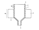
図1は、本発明の実施の形態1におけるに通水制御装置の外観を示す図であり、図1Aは上面図、図1Bは側面図である。図2は、図1に示す通水制御装置の構成を示す断面図であり、図2Aは図1A中の切断線A−A´に沿って切断して得られた断面図であり、図2Bは図1B中の切断線B−B´に沿って切断して得られた断面図である。図1及び図2において矢印(矢印X及びYを除く)は流体の流れ方向を示している。 1A and 1B are views showing an external appearance of a water flow control device according to Embodiment 1 of the present invention. FIG. 1A is a top view and FIG. 1B is a side view. 2 is a cross-sectional view showing the configuration of the water flow control device shown in FIG. 1, and FIG. 2A is a cross-sectional view obtained by cutting along the cutting line AA ′ in FIG. 1A. FIG. 3B is a cross-sectional view obtained by cutting along a cutting line BB ′ in FIG. 1B. 1 and 2, arrows (except for arrows X and Y) indicate the flow direction of the fluid.
図3は、図1に示す通水制御装置を構成する外側部材を示す断面図である。図4は、図1に示す通水制御装置を構成する内側部材を示す図であり、図4Aは側面図であり、図4Bは図4A中の切断線C−C´に沿って切断して得られた断面図である。 FIG. 3 is a cross-sectional view showing an outer member constituting the water flow control device shown in FIG. 1. 4 is a view showing an inner member constituting the water flow control device shown in FIG. 1, FIG. 4A is a side view, and FIG. 4B is cut along a cutting line CC ′ in FIG. 4A. It is sectional drawing obtained.
図5は、図1に示す通水制御装置を構成する弁部材を示す図であり、図5Aは上面図であり、図5Bは図5A中の切断線D−D´に沿って切断して得られた断面図であり、図5Cは図5A中の切断線E−E´に沿って切断して得られた断面図である。 5 is a view showing a valve member constituting the water flow control device shown in FIG. 1, FIG. 5A is a top view, and FIG. 5B is cut along a cutting line DD ′ in FIG. 5A. 5C is a cross-sectional view obtained, and FIG. 5C is a cross-sectional view obtained by cutting along the cutting line EE ′ in FIG. 5A.
図6は、図1に示す通水制御装置において弁部材が開いた状態を示す断面図である。図7は、図1に示す通水制御装置において外側部材を弾性変形させた状態を示す断面図である。なお、図6及び図7も、図2Aと同様に、図1A中の切断線A−A´に沿って切断して得られた断面図である。 FIG. 6 is a cross-sectional view showing a state in which the valve member is opened in the water flow control device shown in FIG. 1. FIG. 7 is a cross-sectional view showing a state where the outer member is elastically deformed in the water flow control device shown in FIG. 1. 6 and 7 are also cross-sectional views obtained by cutting along the cutting line AA ′ in FIG. 1A, similarly to FIG. 2A.
図1A及びBに示すように、通水制御装置1には、流体を供給するためのチューブ2と流体を排出するためのチューブ3とが取り付けられる。通水制御装置1は、チューブ2から供給される流体の通水制御を行う。本明細書において「通水制御」とは、流体の流れ具合を制御することをいう。
As shown in FIGS. 1A and 1B, the water flow control device 1 is provided with a
通水制御装置1は、外力を受けていない状態においては、設定圧力以上の圧力で矢印方向(図1B参照)に供給される流体のみを通過させ、設定圧力より低い圧力で供給される流体は通過させないように構成されている。一方、外力を受けて外側部材4が弾性変形すると、通水制御装置1は、設定圧力より低い圧力で供給される流体も通過させる。この点について以下に具体的に説明する。 In a state where no external force is received, the water flow control device 1 passes only fluid supplied in the direction of the arrow (see FIG. 1B) at a pressure equal to or higher than the set pressure, and the fluid supplied at a pressure lower than the set pressure is It is configured not to pass through. On the other hand, when the outer member 4 is elastically deformed by receiving an external force, the water flow control device 1 also allows a fluid supplied at a pressure lower than the set pressure to pass therethrough. This point will be specifically described below.
図2A及びBに示すように、通水制御装置1は、外側部材4と、内側部材10と、弁部材20とを備えている。外側部材4は、筒状を呈し、上流側の開口5と下流側の開口6とを備えている(図3参照)。同様に、内側部材10も筒状を呈し、上流側の開口16と下流側の開口17とを備えている(図4参照)。
As shown in FIGS. 2A and 2B, the water flow control device 1 includes an outer member 4, an
また、内側部材10は、外側部材4の内部に挿入されている。弁部材20は、内側部材10の下流側の開口17に配置されている。本実施の形態1では、内側部材10の上流側の開口16にチューブ2が接続され、外側部材4の下流側の開口6にチューブ3が接続されている。
The
また、図2A及びBと、図4A及びBとに示すように、内側部材10は、上流側の開口16から下流側の開口17へと向かう方向(流体の流れ方向)に沿って順に、貫通孔14と、外側部材に密着する第1の密着部11とを備えている。貫通孔14は、内側部材10の側壁を厚み方向に貫通している。なお、図4Bにおいて「L1」は、貫通孔14から内側部材10の下流側の開口17までの長さを示している。
Further, as shown in FIGS. 2A and 2B and FIGS. 4A and 4B, the
本実施の形態1では、内側部材10の外周に沿って二本の凸部(リブ)12が形成されている。凸部12の断面は台形状に形成されており、凸部12の頂上部分が第1の密着部11となっている。また、内側部材10における貫通孔14の上流側(開口16側)に位置する部分13は、外側部材の内面に密着するように形成されている。この部分13は、第2の密着部として機能する。以降の説明においては、第2の密着部13とする。
In the first embodiment, two convex portions (ribs) 12 are formed along the outer periphery of the
この構成により、本実施の形態1では、内側部材10は、外側部材4の内部に挿入されると、第1の密着部11と第2の密着部13とによって外側部材4の内面に密着する。従って、図2A及びBに示すように、外側部材4が変形しない限り、外側部材4と内側部材10との間を流体が通過することはない。
With this configuration, in the first embodiment, when the
本実施の形態1では、二本の凸部12が内側部材10形成されているが、凸部の数は限定されるものではない。凸部12の数は、第1の密着部11に求められる密閉性に応じて設定すれば良い。即ち、外側部材4と第1の密着部11との密閉性をできる限り高めるのであれば、凸部12の数は多くすれば良い。一方、後述する第1の密着部11と外側部材4との密着の解除を容易に行えるようにするのであれば、凸部12の数は少なくすれば良い。また、本実施の形態1においては、凸部12は断面が台形状となるように形成されているが、凸部12の断面形状は特に限定されるものではない。凸部の断面形状は、台形以外の三角形や半円形であっても良い。
In the first embodiment, the two
また、図2A及びB、図5A〜Cに示すように、弁部材20は、内側部材10の上流側の開口16から下流側の開口17へと設定圧力以上の圧力で供給される流体のみが弁部材20を通過するように構成されている。本実施の形態1では、弁部材20は、傘状の弁部21と突出部22とを備え、これらによって構成されている。
Further, as shown in FIGS. 2A and 2B and FIGS. 5A to 5C, the
弁部21と突出部22とは、各種ゴム材料や各種熱可塑性エラストマーといった弾性に優れた材料によって、一体的に形成されている。具体的には、ゴム材料としては、天然ゴム、イソプレンゴム、ブタジエンゴム、スチレン−ブタジエンゴム、ニトリルゴム、クロロプレンゴム、ブチルゴム、アクリルゴム、エチレン−プロピレンゴム、ヒドリンゴム、ウレタンゴム、シリコンゴム、フッ素ゴム等が挙げられる。熱可塑性エラストマーとしては、スチレン系、ポリオレフィン系、ポリ塩化ビニル系、ポリウレタン系、ポリエステル系、ポリアミド系、ポリブタジエン系、トランスポリイソプレン系、フッ素ゴム系、塩素性ポリエチレン系等の熱可塑性エラストマーが挙げられる。更に、これらの材料うち、最も好ましい材料としては、シリコンゴムが挙げられる。また、弁部材20の作製は、金型成形によって行うことができる。
The
弁部21は、内側部材10の下流側の開口17を覆うように、即ち、傘の直径が開口17の直径より大きくなるように形成されている。また、弁部21の上流側(傘の裏側)には、環状の接触面25が形成されている。このため、弁部21は、内側部材10の開口17の周辺領域と密着して、開口17を閉塞することができる。
The
突出部22は、弁部21の傘の裏側部分から突出するように形成されている。また、図2に示すように、突出部22は、内側部材10の下流側の開口17から内側部材10の内部に挿入され、更に、弁部21によって下流側の開口17を閉塞させた状態で、内側部材10に固定されている。
The protruding
具体的には、突出部22の表面には突起24が形成されており、突出部22は、この突起24を内側部材10の内部に設けられた段差15に引っ掛けることによって、内側部材10に固定されている。また、突起24と段差15との位置は、突起を段差15に引っ掛けたときに、弁部21の接触面25が内側部材10の開口17の周辺領域に密着するように調整されている。
Specifically, a
また、図2A、図5A及びCに示すように、突出部22は、内側部材10の内部に挿入されたときに、内側部材10の内面との間に流体の流路となる隙間が存在するようにも形成されている。具体的には、突出部22は側面に凹部23を備えており、この凹部23によって、流体の流路となる隙間が形成されている。
Further, as shown in FIGS. 2A, 5 </ b> A and 5 </ b> C, when the
よって、チューブ2から供給された流体は、凹部23と内側部材10の内面との間の隙間を通り、その後、弁部21を押圧する。このとき、この流体が設定圧力以上の圧力で供給されると、図6に示すように、突出部21の弾性変形によって、弁部21による閉塞は解除される。具体的には、設定圧力以上の圧力で流体が供給されると、突出部22は、弁部21の接触面25と内側部材10の開口17の周辺領域との密着が解除されるほど、伸張方向に弾性変形する。この結果、弁部21の接触面25と、内側部材10の開口17の周辺領域との間を流体が流れることとなる。
Therefore, the fluid supplied from the
このように、本実施の形態1では、弁部材20が内側部材10に取り付けられているため、設定圧力以上の圧力で供給される流体のみが通水制御装置1を通過でき、設定圧力より低い圧力で供給される流体の通過は阻止される。また、図2に示した矢印の方向と逆の方向から流体が供給された場合、弁部20は、内側部材の開口17に向けて押圧され、弁部21の接触面25と内側部材10の開口17の周辺領域との密着はより強固となる。つまり、弁部材20は、逆止弁としても機能し、図2A及びBに示した矢印の方向と逆の方向からの流体の通過も阻止している。
Thus, in this Embodiment 1, since the
また、本実施の形態1では、上述した設定圧力の設定は、弁部材20の構成材料や、凹部23と内側部材10の内面との間にできる隙間の断面積等を適宜選定することによって行うことができる。設定圧力の大きさは、通水制御装置1の用途や、ポンプの圧力に応じて決定すれば良い。なお、輸液ポンプやシリンジポンプは、注入回路の内圧が一定値以上となった場合に、警報を発する機能を備えている場合がある。この場合においては、警報が発せられないように上述した設定圧力を調整する必要がある。
In the first embodiment, the setting pressure described above is set by appropriately selecting the constituent material of the
ところで、流体の圧力が設定圧力以上でないと、流体が通水制御装置1を通過できないとすると、通水制御装置1を輸液回路(後述の図8参照)や薬剤注入回路(後述の図9参照)に組み込んだ場合にプライミングが困難となる。このため、図7に示すように、外側部材4(図3参照)は、外力によって弾性変形し、それによって、第1の密着部11との間に、貫通孔14と連通する隙間18を生じさせるように形成されている。
By the way, if the fluid pressure is not equal to or higher than the set pressure, if the fluid cannot pass through the water flow control device 1, the water flow control device 1 is connected to an infusion circuit (see FIG. 8 described later) or a drug injection circuit (see FIG. 9 described later). Priming becomes difficult when it is incorporated. Therefore, as shown in FIG. 7, the outer member 4 (see FIG. 3) is elastically deformed by an external force, thereby generating a
このとき、隙間18は、貫通孔14と共に、弁部材20を介さない新たな流路を形成するため、設定圧力よりも低い圧力で供給される流体も通水制御装置1を通過できる。従って、通水制御装置1を輸液用や薬剤投与用の注入回路に組み込んだ場合において、落差圧によるプライミングが可能となる。
At this time, the
また、本実施の形態1において、外側部材4に弾性変形を生じさせる外力は使用者によって与えられる。本実施の形態1において、想定される外力の大きさは、一般的な人が付加できる程度である。使用者における操作性を向上させるため、即ち、使用者による外側部材4への外力の付加を容易にするため、外側部材4の外面には操作部8及び9が設けられている(図1A及びB参照)。
In the first embodiment, an external force that causes elastic deformation of the outer member 4 is given by the user. In this Embodiment 1, the magnitude | size of the assumed external force is a grade which a general person can add. In order to improve the operability for the user, that is, to make it easier for the user to apply an external force to the outer member 4,
具体的には、操作部8及び9は、外側部材4の外面から突出している部材であり、外側部材4の第2の密着部13と密着している部分4a以外の部分、即ち、部分4b(図3参照)に設けられている。使用者は、操作部8と操作部9とを指で挟み、両者をそれぞれ図1Aに示した矢印V及び矢印Wの方向に動かすだけで、外側部材4を弾性変形させることができる。また、本実施の形態1では、使用者が指でつまみやすいように、操作部8及び9は、翼状に形成され、それぞれの翼面が流体の流れ方向に平行となるように配置されている。
Specifically, the
更に、本実施の形態1では、外側部材4の外面において、部分4aと部分4bとの間には、外側部材4の外周に沿って溝7が形成されている。よって、使用者が操作部8及び9に外力を加えたとき、外側部材4は、溝7を境にして部分4b(図3参照)において、部分4aよりも大きく弾性変形する。このため、本実施の形態1によれば、外側部材4を弾性変形させたときであっても、内側部材の第2の密着部13と外側部材4との密着は確保され、外側部材4と内側部材10との間からの流体の漏洩は抑制される。
Furthermore, in the first embodiment, a
本実施の形態1において、通水制御装置1を上面から見たときの操作部8と操作部9とのなす角は、特に限定されるものではない。操作部8と操作部9とのなす角は、外側部材4の大きさなどを考慮して適宜設定すれば良い。また、操作部8及び9の数も特に限定されるものではなく、使用者の操作性を考慮して適宜設定できる。更に、操作部8及び9の形状は、翼状以外の形状であっても良い。
In the first embodiment, the angle formed between the
また、外側部材4の弾性変形時において、第2の密着部13と外側部材4との密着を確保する点からは、内側部材10の構成材料は、外側部材4の構成材料よりも弾性係数が小さく、弾性変形し難い材料であるのが好ましい。本実施の形態1において、外側部材4の構成材料としては、上述した弁部材20と同様の材料、つまり、各種ゴム材料や各種熱可塑性エラストマーといった弾性に優れた材料が挙げられる。また、内側部材10の構成材料としては、ポリプロピレン(PP)樹脂、ポリカーボネート樹脂、ABS樹脂、ポリエチレンテレフタレート(PET)樹脂、ポリブチレンテレフタレート(PBT)樹脂等が挙げられる。
In addition, when the outer member 4 is elastically deformed, the constituent material of the
また、上述した材料のうち、外側部材4の構成材料としては、ポリ塩化ビニル系熱可塑性エラストマー、及びポリブタジエン系熱可塑性エラストマーを用いるのが好ましく、内側部材10の構成材料としては、ポリカーボネート樹脂を用いるのが好ましい。
Among the materials described above, it is preferable to use polyvinyl chloride thermoplastic elastomer and polybutadiene thermoplastic elastomer as the constituent material of the outer member 4, and polycarbonate resin is used as the constituent material of the
次に、本実施の形態1における注入回路について図8〜図10を用いて説明する。本実施の形態1における注入回路は、図1〜図7を用いて説明した本実施の形態1における通水制御装置1を備えている。本実施の形態1における注入回路は、例えば、輸液回路、薬剤注入回路、観血式血圧測定法で使用される採血回路(Aライン)等として用いることができる。この点について以下に説明する。なお、図8〜図10において、図1〜図7で用いられた符号が付されたものは、図1〜図7において当該符号が付されたものと同一のものを示している。 Next, the injection circuit according to the first embodiment will be described with reference to FIGS. The injection circuit according to the first embodiment includes the water flow control device 1 according to the first embodiment described with reference to FIGS. The injection circuit in the first embodiment can be used as, for example, an infusion circuit, a drug injection circuit, a blood collection circuit (A line) used in an invasive blood pressure measurement method, or the like. This will be described below. 8 to 10, the reference numerals used in FIGS. 1 to 7 are the same as those shown in FIGS. 1 to 7.
図8は、本実施の形態1における注入回路を輸液回路として用いた例を示す図である。図8に示すように、輸液回路30は、輸液バック31と、点滴塔32と、クランプ33と、通水制御装置1と、穿刺針34とを備えている。また、通水制御装置1の流入側に接続されたチューブ2は、点滴塔32に接続されている。更に、チューブ2には、輸液の流れ方向に沿って、順に、輸液ポンプ36とクランプ33とが取り付けられている。また、通水制御装置1の排出側に接続されたチューブ3は、穿刺針34に接続されている。なお、チューブ35は点滴塔32と輸液バック31とを接続している。
FIG. 8 is a diagram showing an example in which the injection circuit according to Embodiment 1 is used as an infusion circuit. As shown in FIG. 8, the
このように、輸液回路30に通水制御装置1を用いれば、クランプ33を閉め忘れた状態(開いた状態)で輸液ポンプ36を取り外してしまっても、輸液は通水制御装置1によってそれ以上先には流れないため、フリーフローの発生が抑制される。また、落差圧によってプライミングを行う場合は、図7に示したように外側部材4を弾性変形させることで、輸液が通水制御装置1を通過することができるため、通水制御装置1を取り付けた状態でプライミングを完了できる。
As described above, when the water flow control device 1 is used for the
なお、図8の例では、通水制御装置1は、クランプ33の下流に配置されているが、この例に限定されるものではない。通水制御装置1は、輸液ポンプと点滴塔32との間の位置に配置することもできる。
In addition, in the example of FIG. 8, although the water flow control apparatus 1 is arrange | positioned downstream of the
図9は、本実施の形態1における注入回路を薬剤注入回路として用いた例を示す図である。図9に示す注入回路は、薬剤注入回路40と、輸液回路30との両方を備えており、薬剤注入回路40と輸液回路30とは三方活栓41を介して接続されている。このため、図9に示す注入回路によれば、輸液の注入と薬剤投与とを同時に行うことができる。更に、図9に示す注入回路によれば、輸液の注入を行いながら間歇的に薬剤投与を行うこともできる。また、図9に示すように、薬剤注入回路40は、輸液回路30と同様に、本実施の形態1における通水制御装置1を備えている。更に、薬剤注入回路40には、シリンジポンプ45が接続されている。
FIG. 9 is a diagram illustrating an example in which the injection circuit according to the first embodiment is used as a drug injection circuit. The injection circuit shown in FIG. 9 includes both a
具体的には、薬剤注入回路40は、通水制御装置1と、通水制御装置1の流入側に接続されたチューブ44と、排出側に接続されたチューブ43とを備えている。チューブ44には、シリンジポンプ45が接続されている。また、シリンジポンプ45にセットされたシリンジには、例えば、抗がん剤、抗生剤、脂肪乳剤、鎮静剤といった微量投与が必要な薬剤が充填されている。チューブ43には、操作性の向上のためクランプ33が取り付けられている。なお、輸液回路30は、図8に示したものと同様のものであり、通水制御装置1を備えている。
Specifically, the
また、三方活栓41の対向するポートの一方に、輸液回路30の通水制御装置1の排出側のチューブ3が接続され、対向するポートの他方に、チューブ42を介して穿刺針34が接続されている。また、三方活栓41の残りのポートには、薬剤注入回路40のチューブ43が接続されている。
Further, the
このように、図9に示す注入回路によれば、三方活栓41のハンドルの切り替えにより、輸液の注入と薬剤の投与とを同時に行ったり、輸液の注入を行いながら薬剤投与を間歇的に行ったりすることができる。また、上述したように、薬剤注入回路40は、通水制御装置1を備えている。このため、シリンジポンプ45においてシリンジがポンプ本体から外れる等しても、通水制御装置1によって必要量以上の薬剤の投与は阻止される。通水制御装置1によれば、シリンジポンプ45を用いた薬剤投与におけるフリーフローの発生も抑制することができる。
As described above, according to the injection circuit shown in FIG. 9, by switching the handle of the three-
また、図8の例と同様に、外側部材4を弾性変形させることで(図7参照)、薬剤注入回路40におけるプライミングも簡単に行うことができる。なお、薬剤注入回路40においては、シリンジポンプ45の早送り機能を利用してプライミングを行うこともできる。
Further, similarly to the example of FIG. 8, the outer member 4 is elastically deformed (see FIG. 7), and the priming in the
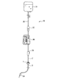
図10は、本実施の形態1における注入回路を採血回路として用いた例を示す図である。図10に示すように、採血回路50は、観血式血圧測定法で使用される採血回路である。採血回路50は、通水制御装置1と、血圧トランスデューサ56と、混注ポート51及び52と、穿刺針55とを備えている。穿刺針55は、患者の動脈59内に留置される。
FIG. 10 is a diagram illustrating an example in which the injection circuit according to the first embodiment is used as a blood collection circuit. As shown in FIG. 10, the
採血回路50において、血圧トランスデューサ56と穿刺針55とは、混注ポート51、チューブ53、混注ポート52、及びチューブ54を介して接続されている。また、通水制御装置1の排出側は、直接、血圧トランスデューサ56に接続されている。通水制御装置1の流入側に接続されたチューブ2は、シリンジポンプ58に接続されている。シリンジポンプ58のシリンジ内には、生理食塩水が充填されている。更に、チューブ2には、操作性の向上のためクランプ33が取り付けられている。
In the
また、採血回路50において、血圧トランスデューサ56から穿刺針55までの流路内には、生理食塩水が充填されている。よって、血圧トランスデューサ56には、流路内に充填された生理食塩水を介して、動脈59を流れる血液の血圧が伝達される。血圧トランスデューサ56は、伝達された血圧の大きさに応じた電気信号をコンピュータ57に出力する。血圧トランスデューサ56が電気信号を出力すると、コンピュータ57は、電気信号によって特定される測定値(血圧値)を画面に表示する。
Further, in the
また、血圧測定中においては、シリンジポンプ58によって、血圧トランスデューサ56から穿刺針55までの流路内に、一定の流量(例えば3ml/h)で、生理食塩水が供給される。更に、シリンジポンプ58のシリンジに充填された生理食塩水には、抗凝固剤が添加されている。これは、動脈59から穿刺針55内に血液が流入した場合に、流入した血液が穿刺針55内で凝固することによって血液測定ができなくなるのを抑制するためである。
During blood pressure measurement, physiological saline is supplied at a constant flow rate (for example, 3 ml / h) into the flow path from the
抗凝固剤としては、例えば、ヘパリン等が挙げられる。図10の例では、シリンジポンプ58のシリンジに充填された生理食塩水は、ヘパリン添加生理食塩水である。以降の説明においては、ヘパリン添加生理食塩水とする。
Examples of the anticoagulant include heparin. In the example of FIG. 10, the physiological saline filled in the syringe of the
また、血液測定の開始前においては、シリンジポンプ58によって、血圧トランスデューサ56から穿刺針55までの流路内に、予め、ヘパリン添加生理食塩水が充填される。なお、図10の例では、流路内へのヘパリン添加生理食塩水の充填は、シリンジポンプ58の早送り機能を利用して行われている。
Prior to the start of blood measurement, heparinized physiological saline is filled in advance into the flow path from the
ところで、図10の例において、血液測定中にシリンジポンプ58のシリンジがポンプ本体から外れてしまうと、ヘパリン添加生理食塩水を一定の流量で供給することが困難となる。このとき、通水制御装置1が取り付けられていないとすると、ヘパリン添加生理食塩水は、落差圧によって供給される。そして、落差圧が血圧より低い場合は、血液が流路内に流入してしまう。また、落差圧が血圧より高い場合は、患者の動脈59内に多量の抗凝固剤(図10の例では、ヘパリン)が注入されてしまう可能性がある。更に、通水制御装置1が取り付けられていない場合に、シリンジがポンプ本体から外れると、伝達されてきた圧力がシリンジポンプ58側へと逃げるため、血圧測定における測定精度が低下してしまう。
In the example of FIG. 10, if the syringe of the
このような問題を回避するため、本実施の形態1では、図10に示すように、通水性制御装置1が取り付けられている。即ち、図10の例では、通水制御装置1は、シリンジポンプがポンプ本体から外れた場合における、血液の流路内への逆流、抗凝固剤(図10の例では、ヘパリン)の人体への流入、及び測定精度の低下を抑制している。 In order to avoid such a problem, in this Embodiment 1, as shown in FIG. 10, the water flow control apparatus 1 is attached. That is, in the example of FIG. 10, the water flow control device 1 causes the blood to flow backward into the flow channel and the anticoagulant (heparin in the example of FIG. 10) to the human body when the syringe pump is removed from the pump body. Inflow and decrease in measurement accuracy.
採血回路50において、混注ポート51及び52は、血圧測定中に採血を行う場合に利用される。具体的には、先ず、穿刺針55から遠い位置にある混注ポート51に接続したシリンジ(図示せず)によって負圧を与え、血液を流路内に流入させる。次いで、穿刺針55から近い位置にある混注ポート52に接続したシリンジ(図示せず)によって流入した血液の採取が行われる。なお、血液の採取後は、シリンジポンプ58の早送り機能を利用して、流路内の洗浄が行われる。
In the
図10の例においては、シリンジポンプ58の代わりに、輸液バックと輸液ポンプとを用いることもできる。この場合においては、図7に示したように外側部材4を弾性変形させ、落差圧を利用することによって、流路内へのヘパリン添加生理食塩水の充填が行われる。
In the example of FIG. 10, an infusion bag and an infusion pump can be used instead of the
(実施の形態2)
次に、本発明の実施の形態2における通水制御装置及び注入回路について、図11及び図12を参照しながら説明する。図11は、本発明の実施の形態2における通水制御装置の断面構成を示す断面図であり、図11A及び図11Bはそれぞれ切断方向が異なる断面を示している。図12は、図11に示す通水制御装置を構成する内側部材を示す図であり、図12Aは側面図であり、図12Bは図12A中の切断線F−F´に沿って切断して得られた断面図である。(Embodiment 2)
Next, a water flow control device and an injection circuit according to
なお、本実施の形態2における通水制御装置の外観は、図1に示した実施の形態1における通水制御装置の外観と同一である。図11Aは、図1中の切断線A−A´に沿って切断して得られた断面図に相当し、図11Bは図1B中の切断線B−B´に沿って切断して得られた断面図に相当する。また、図11及び図12において、図1〜図7に示された符号と同じ符号が付された部分は、図1〜図7において当該符号が付された部分と同様のものを示している。
In addition, the external appearance of the water flow control apparatus in this
図11A、図11B、図12A及び図12Bに示すように、本実施の形態2における通水制御装置は、内側部材60の構成において、実施の形態1における通水制御装置(図2参照)と異なっている。その他においては、本実施の形態2における通水制御装置は、実施の形態1における通水制御装置と同様に構成されている。また、本実施の形態2における注入回路は、本実施の形態2における通水制御装置を備えている。本実施の形態2における注入回路も、例えば、輸液回路、薬剤注入回路、観血式血圧測定法で使用される採血回路(Aライン)等として用いることができる。以下に、相違点について具体的に説明する。
As shown in FIG. 11A, FIG. 11B, FIG. 12A and FIG. 12B, the water flow control device in the present second embodiment is the same as the water flow control device in the first embodiment (see FIG. 2) in the configuration of the
図11A及びBに示すように、本実施の形態2においては、実施の形態1と異なり、内側部材60の貫通孔14は、その開口が内側部材60に取り付けられた弁部材20の突出部22に面する位置に形成されている。更に、図12Bに示すように、本実施の形態2においては、内側部材60の貫通孔14から下流側の開口17までの長さL2は、内側部材10の貫通孔14から下流側の開口17までの長さL1(図4B参照)よりも短くなっている。また、突出部22の突起24は、貫通孔14の内壁61に引っ掛けられて、内側部材60に固定されている。
As shown in FIGS. 11A and 11B, in the second embodiment, unlike the first embodiment, the through
このような内側部材60の構成により、本実施の形態2によれば、外側部材4を弾性変形させてプライミングを行ったときに突起24付近に溜まる空気の量を、実施の形態1に比べて少なくすることができる。このため、プライミングの終了後に設定圧力での送液が行われた場合に、チューブ3内に混入される気泡の量を少なくすることができる。この結果、本実施の形態2における通水制御装置を用いて構成された輸液回路や薬剤注入回路によれば、より一層、患者の安全性を高めることができる。
With the configuration of the
また、本実施の形態2においても、実施の形態1と同様に、設定圧力以上の圧力で供給される流体のみが通水制御装置を通過でき、設定圧力より低い圧力で供給される流体の通過は阻止される。更に、上述したように、外側部材4の弾性変形によって、設定圧力以下の流体を流すための流路が形成される。 Also in the second embodiment, as in the first embodiment, only the fluid supplied at a pressure equal to or higher than the set pressure can pass through the water flow control device, and the fluid supplied at a pressure lower than the set pressure passes. Is blocked. Furthermore, as described above, a flow path for flowing a fluid having a pressure equal to or lower than the set pressure is formed by elastic deformation of the outer member 4.
なお、本実施の形態2においては、上述したように、内側部材60の貫通孔14から下流側の開口17までの長さL2が、実施の形態1よりも短いため、図12A及びBに示すように、凸部12の数は1本となっている。但し、本実施の形態2においても、実施の形態1と同様に、凸部12の数は限定されるものではない。また、内側部材60の構成材料としても、実施の形態1で述べた内側部材10の構成材料を用いることができる。
In the second embodiment, as described above, since the length L2 from the through
(実施の形態3)
次に、本発明の実施の形態3における通水制御装置及び注入回路について、図13及び図14を参照しながら説明する。図13は、本発明の実施の形態3における通水制御装置の外観を示す図であり、図13A及びBはそれぞれ観察方向が異なっている。また、図13Aの観察方向と図13Bの観察方向とは、互いに直交する。図14は、図13に示した通水制御装置の構成を示す断面図であり、図14Aは図13B中の切断線G−G´に沿って切断して得られた断面図、図14Bは図14A中の切断線H−H´に沿って切断して得られた断面図である。(Embodiment 3)
Next, a water flow control device and an injection circuit according to
図13及び図14に示すように、本実施の形態3における通水制御装置は、弁部材20と、内側部材60と、外側部材70とを備えているが、外側部材70は、実施の形態1及び2に示されたものと異なっている。なお、図13及び図14において、図11及び図12で用いられた符号が付されたものは、図11及び図12において当該符号が付されたものと同一のものを示している。
As shown in FIGS. 13 and 14, the water flow control device according to the third embodiment includes the
図14A及びBに示すように、外側部材70の下流側の部分73は先細り状に形成されている。チューブ3は、この先細り状の部分(以下「ノズル部」という。)73の内部に挿入されている。また、外側部材70において、第1の密着部11に密着している部分の下流側の部分には、操作部72a及び72bが設けられている。操作部72a及び72bは、実施の形態1及び2における操作部8及び9と異なり、下流側に向けて突出する一対の部材である。更に、操作部72a及び72bは、両者がノズル73を挟んで対向するように配置されている。
As shown in FIGS. 14A and 14B, the downstream portion 73 of the
また、外側部材70は、第2の密着部13と密着している部分以外の部分(本実施の形態3では、第2の密着部13と密着している部分と操作部72a及び72bとの間の部分)に、薄肉部71を備えている。薄肉部71は、その厚みが、第2の密着部13と密着している部分の厚みよりも薄くなるように形成されており、弾性変形し易くなっている。更に、内側部材60は、各貫通孔14の位置が操作部72a又は操作部72bの位置に整合するように配置されている。
Further, the
この構成により、操作部72a及び72bを、それぞれ図13A及び図14A中の矢印X及びYの方向に動かせば、操作部72a及び72bの基端付近にある薄肉部71は外側に向かって弾性変形する。そして、外側部材70と第1の密着部11との間には、実施の形態1において図7に示した隙間18と同様の隙間が形成される。この結果、本実施の形態3においても、弁部材20を介さない新たな流路が形成され、実施の形態1及び2と同様に、落差圧によるプライミングが可能となる。
With this configuration, if the
また、本実施の形態3において、薄肉部71の厚みt1は、使用者が外力を加えたときに外側部材70が簡単に弾性変形するように、外側部材70の構成材料を考慮して決定すれば良い。例えば、外側部材70が、ポリ塩化ビニル系熱可塑性エラストマー、ポリブタジエン系熱可塑性エラストマー、ポリエチレン、又はポリプロピレン等で形成されているのであれば、厚みt1は、0.1mm〜1mm程度に設定すれば良い。
In the third embodiment, the thickness t1 of the
本実施の形態3における通水制御装置においても、外側部材70が弾性変形していない場合は、実施の形態1及び2と同様に、設定圧力以上の圧力で供給される流体のみが通水制御装置を通過でき、設定圧力より低い圧力で供給される流体の通過は阻止される。また、本実施の形態3における注入回路は、本実施の形態3における通水制御装置を備えている。本実施の形態3における注入回路も、例えば、輸液回路、薬剤注入回路、観血式血圧測定法で使用される採血回路(Aライン)等として用いることができる。
Also in the water flow control device according to the third embodiment, when the
(実施の形態4)
次に、本発明の実施の形態4における通水制御装置及び注入回路について、図15及び図16を参照しながら説明する。図15は、本発明の実施の形態4における通水制御装置の構成を示す断面図であり、図15A及び図15Bはそれぞれ切断方向が異なる断面を示している。図15Aの切断方向と図15Bの切断方向とは互いに直交する。図16は、図15A中の切断線I−I´に沿って切断して得られた断面図であり、図16Aは外側部材が弾性変形していない状態を示し、図16Bは外側部材が弾性変形している状態を示している。(Embodiment 4)
Next, a water flow control device and an injection circuit according to Embodiment 4 of the present invention will be described with reference to FIGS. 15 and 16. FIG. 15 is a cross-sectional view showing the configuration of the water flow control device according to Embodiment 4 of the present invention, and FIGS. 15A and 15B show cross sections with different cutting directions. The cutting direction in FIG. 15A and the cutting direction in FIG. 15B are orthogonal to each other. 16A and 16B are cross-sectional views obtained by cutting along a cutting line II ′ in FIG. 15A. FIG. 16A shows a state where the outer member is not elastically deformed, and FIG. 16B shows that the outer member is elastic. A deformed state is shown.
図15に示すように、本実施の形態4における通水制御装置は、弁部材20と、内側部材60と、外側部材80とを備えているが、外側部材80は、実施の形態1〜3に示されたものと異なっている。なお、図15及び図16において、図11及び図12で用いられた符号が付されたものは、図11及び図12において当該符号が付されたものと同一のものを示している。
As shown in FIG. 15, the water flow control device in the fourth embodiment includes the
図15A及びBに示すように、本実施の形態4においても、実施の形態3と同様に、外側部材80の下流側の部分83は先細り状に形成され、チューブ3は、この先細り状の部分(ノズル部)83の内部に挿入されている。また、本実施の形態4においても、実施の形態3と同様に、外側部材80は、第2の密着部13と密着している部分以外の部分に、薄肉部81を備えている。
As shown in FIGS. 15A and 15B, also in the fourth embodiment, as in the third embodiment, the
但し、本実施の形態4においては、実施の形態3と異なり、外側部材80において、第2の密着部13と密着している部分とノズル部83との間が、全て薄肉部81となっている。また、本実施の形態4においては、実施の形態1〜3と異なり、外側部材80には操作部が設けられていないが、薄肉部81の面積が広いため、使用者は簡単に外側部材80を弾性変形させることができる。
However, in the fourth embodiment, unlike the third embodiment, the
図16A及びBに示すように、使用者は、外側部材80の半径方向において貫通孔14の開口に重ならない領域82(図15A参照)を押圧することによって、外側部材80と第1の密着部11との間に隙間(図7参照)を形成することができる。この結果、本実施の形態4においても、弁部材20を介さない新たな流路が形成され、実施の形態1及び2と同様に、落差圧によるプライミングが可能となる。このように、本実施の形態4によれば、実施の形態1〜3と異なり、外側部材80に操作部を設けることなく、外側部材80を簡単に弾性変形させることができる。よって、外側部材80の製造コストの低減化を図ることができる。
As shown in FIGS. 16A and 16B, the user presses a region 82 (see FIG. 15A) that does not overlap the opening of the through
また、本実施の形態4おいても、薄肉部81の厚みt2は、外側部材80の構成材料を考慮して決定すれば良い。例えば、外側部材80が、ポリ塩化ビニル系熱可塑性エラストマー、ポリブタジエン系熱可塑性エラストマー、ポリエチレン、又はポリプロピレン等で形成されているのであれば、厚みt2は、0.1mm〜1mm程度に設定すれば良い。
Also in the fourth embodiment, the thickness t2 of the
また、本実施の形態4においては、薄肉部81の面積を確保するため、薄肉部81は次の条件を満たす円柱状又は円錐状であるのが好ましい。即ち、外側部材80の中心軸方向(流れ方向)における、薄肉部81の上流側の端から下流側の端までの長さをMとし、薄肉部81での最大内径をDとしたときに、最大内径Dに対する長さMの比(M/D)が、1〜5となるのが好ましい。
Moreover, in this Embodiment 4, in order to ensure the area of the
本実施の形態4における通水制御装置においても、外側部材80が弾性変形していない場合は、実施の形態1及び2と同様に、設定圧力以上の圧力で供給される流体のみが通水制御装置を通過でき、設定圧力より低い圧力で供給される流体の通過は阻止される。また、本実施の形態4における注入回路は、本実施の形態4における通水制御装置を備えている。本実施の形態4における注入回路も、例えば、輸液回路、薬剤注入回路、観血式血圧測定法で使用される採血回路(Aライン)等として用いることができる。
Also in the water flow control device according to the fourth embodiment, when the
以上のように、本発明における通水制御装置及び注入回路は、輸液回路や薬液注入回路の構成部品として適用でき、産業上の利用可能性を有するものである。 As described above, the water flow control device and the injection circuit according to the present invention can be applied as components of an infusion circuit or a chemical solution injection circuit, and have industrial applicability.
Claims (7)
前記内側部材は、前記内側部材の一方の開口から他方の開口へと向かう方向に沿って順に、前記内側部材の側壁を厚み方向に貫通するプライミング用貫通孔と、前記外側部材に密着する密着部とを備え、
前記弁部材は、前記内側部材の前記他方の開口に配置され、前記内側部材の前記一方の開口から前記他方の開口へと設定圧力以上の圧力で供給される流体のみを通過させ、
前記外側部材は、弾性変形でき、且つ、それによって、前記密着部との間に、前記プライミング用貫通孔と連通する隙間を生じさせるように形成され、
前記隙間は、前記プライミング用貫通孔と共に流体の流路を形成し、
前記内側部材が、前記プライミング用貫通孔の前記一方側に位置する部分に、前記外側部材と密着する第2の密着部を更に備え、
前記外側部材が、前記第2の密着部と密着している部分以外の部分において、前記第2の密着部と密着している部分よりも大きな弾性変形が生じるように形成されており、
前記外側部材の前記第2の密着部と密着している部分以外の部分に、前記外側部材の外面から突出する部材が設けられていることを特徴とする医療用通水制御装置。A cylindrical outer member, a cylindrical inner member inserted into the outer member, and a valve member;
The inner member includes a priming through-hole that penetrates the side wall of the inner member in the thickness direction in order along a direction from one opening of the inner member to the other opening, and an adhesion portion that is in close contact with the outer member And
The valve member is disposed in the other opening of the inner member, and allows only fluid supplied at a pressure equal to or higher than a set pressure from the one opening of the inner member to the other opening,
The outer member can be elastically deformed, thereby forming a gap communicating with the priming through-hole between the close contact portion,
The gap forms a fluid flow path with the priming through hole ,
The inner member further includes a second contact portion that is in close contact with the outer member at a portion located on the one side of the priming through-hole,
The outer member is formed such that a larger elastic deformation occurs in a portion other than the portion in close contact with the second close contact portion than in the portion in close contact with the second close contact portion,
A medical water flow control device , wherein a member protruding from the outer surface of the outer member is provided in a portion other than the portion in close contact with the second contact portion of the outer member .
前記突出部は、前記内側部材の内部に挿入されたときに、前記内側部材の内面との間に流体の流路となる隙間が存在するよう形成され、且つ、前記弁部によって前記内側部材の前記他方の開口を閉塞させた状態で前記内側部材に固定され、更に、前記設定圧力以上の圧力で、前記内側部材の内面と前記突出部との間の前記隙間を介して供給された流体によって、前記弁部が押圧されると、弾性変形して前記弁部による閉塞を解除する請求項1に記載の医療用通水制御装置。The valve member covers the other opening of the inner member, and an umbrella-shaped valve portion formed so as to be able to close the valve member, protrudes from the valve portion, and extends from the other opening of the inner member. A protrusion inserted into the inner member;
The protrusion is formed such that when inserted into the inner member, a gap serving as a fluid flow path exists between the inner member and the inner surface of the inner member. The fluid is fixed to the inner member in a state in which the other opening is closed, and further supplied by the fluid supplied through the gap between the inner surface of the inner member and the protruding portion at a pressure equal to or higher than the set pressure. The medical water flow control device according to claim 1, wherein when the valve portion is pressed, the medical water flow control device is elastically deformed to release the blockage by the valve portion.
前記内側部材は、前記内側部材の一方の開口から他方の開口へと向かう方向に沿って順に、前記内側部材の側壁を厚み方向に貫通するプライミング用貫通孔と、前記外側部材に密着する密着部とを備え、
前記弁部材は、前記内側部材の前記他方の開口に配置され、前記内側部材の前記一方の開口から前記他方の開口へと設定圧力以上の圧力で供給される流体のみを通過させ、
前記外側部材は、弾性変形でき、且つ、それによって、前記密着部との間に、前記プライミング用貫通孔と連通する隙間を生じさせるように形成され、
前記隙間は、前記プライミング用貫通孔と共に流体の流路を形成し、
前記内側部材が、前記プライミング用貫通孔の前記一方側に位置する部分に、前記外側部材と密着する第2の密着部を更に備え、
前記外側部材が、前記第2の密着部と密着している部分以外の部分において、前記第2の密着部と密着している部分よりも大きな弾性変形が生じるように形成されており、
前記外側部材の前記他方側の部分が、先細り状に形成され、
前記外側部材における、前記密着部と密着している部分の前記他方側の部分に、前記他方側に向けて突出する一対の部材が設けられ、
前記一対の部材は、その一方と他方とが前記先細り状に形成された部分を挟んで対向するように配置されていることを特徴とする医療用通水制御装置。 A cylindrical outer member, a cylindrical inner member inserted into the outer member, and a valve member;
The inner member includes a priming through-hole that penetrates the side wall of the inner member in the thickness direction in order along a direction from one opening of the inner member to the other opening, and an adhesion portion that is in close contact with the outer member And
The valve member is disposed in the other opening of the inner member, and allows only fluid supplied at a pressure equal to or higher than a set pressure from the one opening of the inner member to the other opening,
The outer member can be elastically deformed, thereby forming a gap communicating with the priming through-hole between the close contact portion,
The gap forms a fluid flow path with the priming through hole,
The inner member further includes a second contact portion that is in close contact with the outer member at a portion located on the one side of the priming through-hole,
The outer member is formed such that a larger elastic deformation occurs in a portion other than the portion in close contact with the second close contact portion than in the portion in close contact with the second close contact portion,
A portion on the other side of the outer member is formed in a tapered shape;
A pair of members projecting toward the other side is provided on the other side portion of the outer member, which is in close contact with the contact portion,
It said pair of members, the one and the other and is medical water flow control apparatus characterized by being arranged so as to face each other across the portion formed on the tapered.
前記第1のチューブは、前記医療用通水制御装置の内側部材の一方の開口に接続され、
前記第2のチューブは、前記医療用通水制御装置の外側部材の他方の開口に接続されていることを特徴とする医療用注入回路。The medical water flow control device according to any one of claims 1 to 6 , comprising at least a first tube and a second tube,
The first tube is connected to one opening of the inner member of the medical water flow control device,
The medical injection circuit, wherein the second tube is connected to the other opening of the outer member of the medical water flow control device.
Priority Applications (1)
| Application Number | Priority Date | Filing Date | Title |
|---|---|---|---|
| JP2007554881A JP4735646B2 (en) | 2006-01-17 | 2007-01-15 | Water flow control device and medical injection circuit using the same |
Applications Claiming Priority (4)
| Application Number | Priority Date | Filing Date | Title |
|---|---|---|---|
| JP2006009123 | 2006-01-17 | ||
| JP2006009123 | 2006-01-17 | ||
| JP2007554881A JP4735646B2 (en) | 2006-01-17 | 2007-01-15 | Water flow control device and medical injection circuit using the same |
| PCT/JP2007/050424 WO2007083599A1 (en) | 2006-01-17 | 2007-01-15 | Water passage control device and medical infusion circuit using the same |
Publications (2)
| Publication Number | Publication Date |
|---|---|
| JPWO2007083599A1 JPWO2007083599A1 (en) | 2009-06-11 |
| JP4735646B2 true JP4735646B2 (en) | 2011-07-27 |
Family
ID=38287552
Family Applications (1)
| Application Number | Title | Priority Date | Filing Date |
|---|---|---|---|
| JP2007554881A Active JP4735646B2 (en) | 2006-01-17 | 2007-01-15 | Water flow control device and medical injection circuit using the same |
Country Status (6)
| Country | Link |
|---|---|
| US (1) | US8186384B2 (en) |
| EP (1) | EP1980291A1 (en) |
| JP (1) | JP4735646B2 (en) |
| KR (1) | KR101045119B1 (en) |
| CN (1) | CN101374567B (en) |
| WO (1) | WO2007083599A1 (en) |
Cited By (1)
| Publication number | Priority date | Publication date | Assignee | Title |
|---|---|---|---|---|
| JP2014030489A (en) * | 2012-08-01 | 2014-02-20 | Jms Co Ltd | Infusion set, and method of using the same |
Families Citing this family (24)
| Publication number | Priority date | Publication date | Assignee | Title |
|---|---|---|---|---|
| US7600530B2 (en) * | 2004-08-09 | 2009-10-13 | Medegen, Inc. | Connector with check valve and method of use |
| US10478607B2 (en) | 2004-08-09 | 2019-11-19 | Carefusion 303, Inc. | Connector for transferring fluid and method of use |
| JP5175778B2 (en) * | 2009-03-11 | 2013-04-03 | 株式会社東芝 | Liquid feeding device |
| WO2012003776A1 (en) * | 2010-07-08 | 2012-01-12 | 厦门松霖科技有限公司 | Water-saving check valve |
| JP5998499B2 (en) * | 2011-02-14 | 2016-09-28 | 株式会社ジェイ・エム・エス | Extension tube |
| KR101272789B1 (en) * | 2011-05-23 | 2013-06-10 | 주식회사 엠스코 | Drain valve for vehicle |
| TW201305470A (en) * | 2011-07-22 | 2013-02-01 | Techarme Apparel Co Ltd | Air valve device |
| CN102512726B (en) * | 2012-01-17 | 2013-07-10 | 南京扬子医用制品有限公司 | Microinfusion pump |
| WO2014179326A1 (en) | 2013-05-01 | 2014-11-06 | Bayer Medical Care Inc. | Fluid path set bolus control device |
| JP5559396B2 (en) * | 2013-05-24 | 2014-07-23 | 日機装株式会社 | Valve device, infusion set and infusion device |
| JP6260776B2 (en) * | 2014-02-14 | 2018-01-17 | Smc株式会社 | Oxygen concentrator |
| CN106163608B (en) * | 2014-03-26 | 2019-07-26 | 泰尔茂株式会社 | Connector and infusion set |
| PL2924285T3 (en) * | 2014-03-26 | 2018-03-30 | Erbe Elektromedizin Gmbh | Sterilisable pump unit |
| WO2016130505A1 (en) * | 2015-02-09 | 2016-08-18 | Vernay Laboratories, Inc. | Umbrella check valve with reduce hemolysis |
| JP6544114B2 (en) * | 2015-07-27 | 2019-07-17 | 浜名湖電装株式会社 | Check valve device and evaporated fuel supply system |
| EP3349826B1 (en) * | 2015-09-17 | 2023-04-12 | Oxular Limited | Ophthalmic injection device |
| CN106246975B (en) * | 2016-08-30 | 2018-09-14 | 江苏永冠给排水设备有限公司 | A kind of fluid flow constant control device |
| US11052234B2 (en) * | 2017-02-15 | 2021-07-06 | Celeste V. Bonham | Connector with integrated non-return check valve for extension tubing and urology collection systems |
| KR101862201B1 (en) * | 2017-08-31 | 2018-05-29 | 제이에스케이바이오메드(주) | Micro-jet drug injection device with backflow prevention valve |
| JP7279638B2 (en) * | 2017-11-09 | 2023-05-23 | ニプロ株式会社 | Flash devices and irrigation lines |
| CN108853649B (en) * | 2018-05-10 | 2021-03-12 | 青岛大学附属医院 | Medical nursing syringe |
| US11306833B2 (en) * | 2018-05-26 | 2022-04-19 | Eos Energy Storage, Llc | Pressure relief valve assembly |
| JP6995150B2 (en) | 2020-01-15 | 2022-01-14 | 株式会社コメッツ | Infusion set |
| EP4006339A1 (en) | 2020-11-27 | 2022-06-01 | Erbe Elektromedizin GmbH | Pump unit for medical purposes |
Citations (4)
| Publication number | Priority date | Publication date | Assignee | Title |
|---|---|---|---|---|
| JPS5142772B1 (en) * | 1970-03-26 | 1976-11-17 | ||
| JPS6128624Y2 (en) * | 1984-06-25 | 1986-08-25 | ||
| JPH0453761Y2 (en) * | 1987-11-27 | 1992-12-17 | ||
| WO2004016314A1 (en) * | 2002-08-13 | 2004-02-26 | Jms Co.,Ltd. | Fluid control device |
Family Cites Families (12)
| Publication number | Priority date | Publication date | Assignee | Title |
|---|---|---|---|---|
| JPS5142772A (en) | 1974-10-08 | 1976-04-12 | Sumitomo Electric Industries | Horiechiren kakyohoriechirenno chakushokuhoho |
| JPH0713333B2 (en) | 1984-11-20 | 1995-02-15 | 東レ株式会社 | Alternate twisted yarn manufacturing method |
| JPH024681Y2 (en) * | 1985-01-24 | 1990-02-05 | ||
| US4642097A (en) * | 1985-03-25 | 1987-02-10 | Siposs George G | Left ventrical vacuum control and pressure relief valve |
| US4725266A (en) * | 1985-03-25 | 1988-02-16 | Siposs George G | Left ventricle vacuum control and pressure relief valve |
| JP4010005B2 (en) | 2000-02-29 | 2007-11-21 | ニプロ株式会社 | Device for adjusting injection speed of chemical injector |
| US7150727B2 (en) | 2000-05-11 | 2006-12-19 | Zevex, Inc. | Apparatus and method for preventing free flow in an infusion line |
| EP1166818A1 (en) | 2000-06-29 | 2002-01-02 | Societe Des Produits Nestle S.A. | Medium cracking pressure valve |
| JP2002095744A (en) | 2000-09-26 | 2002-04-02 | Terumo Corp | Flow rate regulator |
| JP4369139B2 (en) | 2002-06-17 | 2009-11-18 | テルモ株式会社 | Clamp and infusion device using the same |
| US7278445B2 (en) * | 2002-07-02 | 2007-10-09 | Reebok International Ltd. | Shoe having an inflatable bladder |
| JP3976142B2 (en) | 2003-06-25 | 2007-09-12 | 日機装株式会社 | Check valve |
-
2007
- 2007-01-15 WO PCT/JP2007/050424 patent/WO2007083599A1/en active Application Filing
- 2007-01-15 CN CN2007800032373A patent/CN101374567B/en not_active Expired - Fee Related
- 2007-01-15 KR KR1020087016669A patent/KR101045119B1/en not_active IP Right Cessation
- 2007-01-15 EP EP20070706758 patent/EP1980291A1/en not_active Withdrawn
- 2007-01-15 JP JP2007554881A patent/JP4735646B2/en active Active
- 2007-01-15 US US12/087,726 patent/US8186384B2/en not_active Expired - Fee Related
Patent Citations (4)
| Publication number | Priority date | Publication date | Assignee | Title |
|---|---|---|---|---|
| JPS5142772B1 (en) * | 1970-03-26 | 1976-11-17 | ||
| JPS6128624Y2 (en) * | 1984-06-25 | 1986-08-25 | ||
| JPH0453761Y2 (en) * | 1987-11-27 | 1992-12-17 | ||
| WO2004016314A1 (en) * | 2002-08-13 | 2004-02-26 | Jms Co.,Ltd. | Fluid control device |
Cited By (2)
| Publication number | Priority date | Publication date | Assignee | Title |
|---|---|---|---|---|
| JP2014030489A (en) * | 2012-08-01 | 2014-02-20 | Jms Co Ltd | Infusion set, and method of using the same |
| US9795736B2 (en) | 2012-08-01 | 2017-10-24 | Jms Co., Ltd. | Infusion set and method for using same |
Also Published As
| Publication number | Publication date |
|---|---|
| KR101045119B1 (en) | 2011-06-30 |
| JPWO2007083599A1 (en) | 2009-06-11 |
| WO2007083599A1 (en) | 2007-07-26 |
| CN101374567A (en) | 2009-02-25 |
| CN101374567B (en) | 2011-01-26 |
| US8186384B2 (en) | 2012-05-29 |
| US20090018513A1 (en) | 2009-01-15 |
| KR20080082685A (en) | 2008-09-11 |
| EP1980291A1 (en) | 2008-10-15 |
Similar Documents
| Publication | Publication Date | Title |
|---|---|---|
| JP4735646B2 (en) | Water flow control device and medical injection circuit using the same | |
| JP5023121B2 (en) | Fluid control device for drug supply | |
| US10881787B2 (en) | Wearable liquid supplying device for human insulin injection | |
| US6692457B2 (en) | Flow condition sensor assembly for patient infusion device | |
| JP5215632B2 (en) | Connector priming method | |
| US8016790B2 (en) | Infusion status indicator | |
| KR200449368Y1 (en) | a medicinal fluid injector | |
| JPH04246370A (en) | Cardiovascular assembly | |
| US11147931B2 (en) | Drug delivery device with air and backflow elimination | |
| WO2007132732A1 (en) | Indwelling needle assembly | |
| WO2007049564A1 (en) | Indwelling needle assembly | |
| JP4970430B2 (en) | Indwelling needle assembly | |
| JP4600280B2 (en) | Chemical solution supply control device and chemical solution administration set using the device | |
| JP2005296142A (en) | Liquid supply line for medical purpose | |
| KR20110001641U (en) | Three-finger tube for preventing backflow of medicinal fluid | |
| JP4919008B2 (en) | Water flow control device and liquid injection circuit using the same | |
| JP5057133B2 (en) | Injection circuit and water flow control tool used therefor | |
| JP2637579B2 (en) | Balloon infuser | |
| JP4433141B2 (en) | Medical mixed injection tube | |
| JPH0523308A (en) | Flow controller and blood pressure measuring apparatus | |
| KR20210108373A (en) | overmolded diaphragm |
Legal Events
| Date | Code | Title | Description |
|---|---|---|---|
| A131 | Notification of reasons for refusal |
Free format text: JAPANESE INTERMEDIATE CODE: A131 Effective date: 20100112 |
|
| A521 | Request for written amendment filed |
Free format text: JAPANESE INTERMEDIATE CODE: A523 Effective date: 20100309 |
|
| A02 | Decision of refusal |
Free format text: JAPANESE INTERMEDIATE CODE: A02 Effective date: 20100930 |
|
| A521 | Request for written amendment filed |
Free format text: JAPANESE INTERMEDIATE CODE: A523 Effective date: 20101227 |
|
| A911 | Transfer to examiner for re-examination before appeal (zenchi) |
Free format text: JAPANESE INTERMEDIATE CODE: A911 Effective date: 20110107 |
|
| TRDD | Decision of grant or rejection written | ||
| A01 | Written decision to grant a patent or to grant a registration (utility model) |
Free format text: JAPANESE INTERMEDIATE CODE: A01 Effective date: 20110329 |
|
| A61 | First payment of annual fees (during grant procedure) |
Free format text: JAPANESE INTERMEDIATE CODE: A61 Effective date: 20110411 |
|
| R150 | Certificate of patent or registration of utility model |
Ref document number: 4735646 Country of ref document: JP Free format text: JAPANESE INTERMEDIATE CODE: R150 Free format text: JAPANESE INTERMEDIATE CODE: R150 |
|
| FPAY | Renewal fee payment (event date is renewal date of database) |
Free format text: PAYMENT UNTIL: 20140513 Year of fee payment: 3 |
|
| R250 | Receipt of annual fees |
Free format text: JAPANESE INTERMEDIATE CODE: R250 |
|
| R250 | Receipt of annual fees |
Free format text: JAPANESE INTERMEDIATE CODE: R250 |
|
| R250 | Receipt of annual fees |
Free format text: JAPANESE INTERMEDIATE CODE: R250 |
|
| R250 | Receipt of annual fees |
Free format text: JAPANESE INTERMEDIATE CODE: R250 |
|
| R250 | Receipt of annual fees |
Free format text: JAPANESE INTERMEDIATE CODE: R250 |
|
| R250 | Receipt of annual fees |
Free format text: JAPANESE INTERMEDIATE CODE: R250 |
|
| R250 | Receipt of annual fees |
Free format text: JAPANESE INTERMEDIATE CODE: R250 |
|
| R250 | Receipt of annual fees |
Free format text: JAPANESE INTERMEDIATE CODE: R250 |
|
| R250 | Receipt of annual fees |
Free format text: JAPANESE INTERMEDIATE CODE: R250 |
|
| R250 | Receipt of annual fees |
Free format text: JAPANESE INTERMEDIATE CODE: R250 |
|
| R250 | Receipt of annual fees |
Free format text: JAPANESE INTERMEDIATE CODE: R250 |