JP4715863B2 - Actuator control apparatus, actuator control method, actuator, robot apparatus, and computer program - Google Patents
Actuator control apparatus, actuator control method, actuator, robot apparatus, and computer program Download PDFInfo
- Publication number
- JP4715863B2 JP4715863B2 JP2008119508A JP2008119508A JP4715863B2 JP 4715863 B2 JP4715863 B2 JP 4715863B2 JP 2008119508 A JP2008119508 A JP 2008119508A JP 2008119508 A JP2008119508 A JP 2008119508A JP 4715863 B2 JP4715863 B2 JP 4715863B2
- Authority
- JP
- Japan
- Prior art keywords
- joint
- torque
- value
- actuator
- force
- Prior art date
- Legal status (The legal status is an assumption and is not a legal conclusion. Google has not performed a legal analysis and makes no representation as to the accuracy of the status listed.)
- Active
Links
Images


Classifications
-
- B—PERFORMING OPERATIONS; TRANSPORTING
- B25—HAND TOOLS; PORTABLE POWER-DRIVEN TOOLS; MANIPULATORS
- B25J—MANIPULATORS; CHAMBERS PROVIDED WITH MANIPULATION DEVICES
- B25J9/00—Programme-controlled manipulators
- B25J9/16—Programme controls
- B25J9/1628—Programme controls characterised by the control loop
- B25J9/1633—Programme controls characterised by the control loop compliant, force, torque control, e.g. combined with position control
-
- G—PHYSICS
- G05—CONTROLLING; REGULATING
- G05B—CONTROL OR REGULATING SYSTEMS IN GENERAL; FUNCTIONAL ELEMENTS OF SUCH SYSTEMS; MONITORING OR TESTING ARRANGEMENTS FOR SUCH SYSTEMS OR ELEMENTS
- G05B2219/00—Program-control systems
- G05B2219/30—Nc systems
- G05B2219/39—Robotics, robotics to robotics hand
- G05B2219/39319—Force control, force as reference, active compliance
-
- G—PHYSICS
- G05—CONTROLLING; REGULATING
- G05B—CONTROL OR REGULATING SYSTEMS IN GENERAL; FUNCTIONAL ELEMENTS OF SUCH SYSTEMS; MONITORING OR TESTING ARRANGEMENTS FOR SUCH SYSTEMS OR ELEMENTS
- G05B2219/00—Program-control systems
- G05B2219/30—Nc systems
- G05B2219/39—Robotics, robotics to robotics hand
- G05B2219/39355—Observer, disturbance observer
-
- Y—GENERAL TAGGING OF NEW TECHNOLOGICAL DEVELOPMENTS; GENERAL TAGGING OF CROSS-SECTIONAL TECHNOLOGIES SPANNING OVER SEVERAL SECTIONS OF THE IPC; TECHNICAL SUBJECTS COVERED BY FORMER USPC CROSS-REFERENCE ART COLLECTIONS [XRACs] AND DIGESTS
- Y10—TECHNICAL SUBJECTS COVERED BY FORMER USPC
- Y10T—TECHNICAL SUBJECTS COVERED BY FORMER US CLASSIFICATION
- Y10T74/00—Machine element or mechanism
- Y10T74/20—Control lever and linkage systems
- Y10T74/20207—Multiple controlling elements for single controlled element
- Y10T74/20305—Robotic arm
- Y10T74/20317—Robotic arm including electric motor
Abstract
Description
本発明は、ロボットの関節部の駆動などに用いられるアクチュエータを制御するアクチュエータ制御装置及びアクチュエータ制御方法、アクチュエータ、ロボット装置、並びにコンピュータ・プログラムに係り、特に、関節発生力を直接的に制御する力制御方式により関節アクチュエータの駆動を制御するアクチュエータ制御装置及びアクチュエータ制御方法、アクチュエータ、ロボット装置、並びにコンピュータ・プログラムに関する。 The present invention relates to an actuator control apparatus and actuator control method for controlling an actuator used for driving a joint portion of a robot, an actuator, a robot apparatus, and a computer program, and more particularly to a force for directly controlling a joint generation force. The present invention relates to an actuator control apparatus and actuator control method for controlling the driving of a joint actuator by a control method, an actuator, a robot apparatus, and a computer program.
さらに詳しくは、本発明は、関節部に存在する摩擦や関節といったモデル化や同定が困難な外乱の要因に対処しながら対人物理インタラクションに適した力制御を行なうアクチュエータ制御装置及びアクチュエータ制御方法、アクチュエータ、ロボット装置、並びにコンピュータ・プログラムに係り、特に、ロボットのダイナミクスを考慮しながら機体の所定部位に所望の力を発生するための関節力を算出することにより外乱の問題に対処して、対人物理インタラクションに適した力制御を行なうアクチュエータ制御装置及びアクチュエータ制御方法、アクチュエータ、ロボット装置、並びにコンピュータ・プログラムに関する。 More specifically, the present invention relates to an actuator control device, an actuator control method, and an actuator that perform force control suitable for interpersonal physical interaction while dealing with disturbance factors that are difficult to model and identify such as friction and joints existing in a joint. , the robot apparatus, and a computer program, in particular, addresses the disturbance problem by calculating a joint force for generating a desired force in a predetermined part of the aircraft, taking into account the dynamics of the robot, interpersonal physical The present invention relates to an actuator control apparatus and an actuator control method for performing force control suitable for interaction, an actuator, a robot apparatus, and a computer program.
経済発展に伴い、少子化若しくは年少人口の低位安定化と中年以下の死亡率の低下というメカニズムが作用し、結果として、高齢人口が相対的する現象が急激に進行している。高齢者とそれを支える生産年齢人口の比率は、2005年当時では1人:3.3人であったが、2015年には1人:2.4人に、2025年には1人:2.1人になると見込まれている。かかる高齢化社会においては、高齢者が、できる限り要介護状態とならず健康で活き活きと暮らせること、あるいは、要介護状態となってもできる限り悪化を防ぎ、自立した生活を送ることができる社会とすることが急務である。 Along with the economic development, the mechanism of the declining birthrate or the stabilization of the young population and the lowering of the mortality rate under the middle age is acting, and as a result, the phenomenon of the elderly population is advancing rapidly. The ratio of the elderly to the working-age population that supported it was 1: 3.3 in 2005, but in 2015 it was 1: 2.4 and in 2025 it was 1: 2. . Expected to be alone. In such an aging society, it is possible for the elderly to live in a healthy and lively state without being in need of nursing care as much as possible, or to be able to lead an independent life by preventing deterioration as much as possible even in the state of needing nursing care. Is an urgent need.
また、高齢者介護施設や高齢者を抱える家庭では、高齢者の心身の補助を行なうことを主な目的としたメカトロ機器への要求が高まってきている。 Further, in elderly care homes and homes with elderly people, there is an increasing demand for mechatronic devices whose main purpose is to assist the mind and body of elderly people.
例えば、高齢者介護施設・病院等での悪臭の原因となり、さらに院内感染の原因となり得る排泄物を即時衛生的除去に利用することのできる悪臭源検出排除装置について提案がなされている(例えば、特許文献1を参照のこと)。また、高齢者の動作を検知した第1の検知結果を基に、高齢者の行動を近親者宅のロボットで表出させる一方、近親者の見守り動作を検知した第2の検知結果から近親者の関心度を推定し、その結果をフィードバックさせることでロボットの行動表出に変化を与える行動表現システムについて提案がなされている(例えば、特許文献2を参照のこと)。 For example, an odor source detection / exclusion device has been proposed that can be used for immediate sanitary removal of excreta that can cause odors in elderly care facilities / hospitals and can also cause nosocomial infections (for example, (See Patent Document 1). In addition, based on the first detection result of detecting the motion of the elderly person, the behavior of the elderly person is expressed by the robot at the close relative's house, while the close relative is determined from the second detection result of detecting the close watch operation of the close relative. A behavior expression system that changes the behavioral expression of a robot by estimating the degree of interest and feeding back the result is proposed (see, for example, Patent Document 2).
最近では、自律歩行補助器や上肢のパワーアシストといった物理的な補助に留まらず、ロボットを作業療法の中に効果的に取り入れた、メンタル・アシストへの要求もさらに増してきている。 Recently, there is an increasing demand for mental assistance that effectively incorporates robots into occupational therapy, as well as physical assistance such as autonomous walking aids and power assistance for the upper limbs.
上述したような分野において適用されるメカトロ機器は、人や複雑な実環境と柔軟且つ安全に物理接触しながら、作業を遂行しなければならない。つまり、従来の産業ロボットが既知環境下で固定的動作を行なっていたのとは異なり、未知の環境をセンシングし、時々刻々と変化する周囲環境から適切な外力を得て、目的の作業(タスク)が達成されるようにアクチュエータの発生力を適切に調整しなければならない、と本発明者は思料する。 Mechatronics equipment applied in the fields as described above must perform work while making physical contact with people and complex real environments flexibly and safely. In other words, unlike conventional industrial robots that perform fixed operations in a known environment, they sense the unknown environment, obtain appropriate external forces from the surrounding environment that changes from moment to moment, and perform the desired work (task The inventor believes that the generated force of the actuator must be appropriately adjusted so that
ここで、ロボットは、基本的には複数のリンクとリンク可動部分である関節で構成される多リンク構造体であり、DCブラシレス・モータなどからなるアクチュエータを用いて各関節を駆動するように構成されている。また、かかるロボット(若しくはロボットを構成する関節アクチュエータ)の制御方法として、例えば位置制御と力制御が挙げられる。位置制御は、アクチュエータに対し角度などの位置指令値を与え、指令値に追従するように関節を駆動する制御方法である。他方の力制御は、作業対象に対して加えるべき力の目標値を直接的に受け、その目標値が示す力を実現する制御方法であり、関節発生力を直接制御し、力を直接的に制御することができる。 Here, the robot is basically a multi-link structure composed of a plurality of links and joints that are link movable parts, and is configured to drive each joint using an actuator such as a DC brushless motor. Has been. Moreover, as a control method of such a robot (or a joint actuator constituting the robot), for example, position control and force control can be cited. Position control is a control method in which a position command value such as an angle is given to an actuator, and a joint is driven so as to follow the command value. The other force control is a control method that directly receives the target value of the force to be applied to the work target and realizes the force indicated by the target value, directly controls the joint generation force, and directly applies the force. Can be controlled.
従来のロボット装置は、制御上の簡便さやシステムの構成し易さから、位置制御によって駆動されるものが大半である。しかしながら、位置制御は、基本的に位置を保持することが目的であることから、俗に「硬い制御」と呼ばれ、外力に柔軟に応じたり、速度や加速度のオーダーでの「やわらかい」制御を精密に行なったりするのには適さない。例えば、多様な外界との物理インタラクションを行ないながらタスクを遂行するロボット装置は、本来は位置制御との親和性は低い。 Most conventional robotic devices are driven by position control because of ease of control and system configuration. However, since position control is basically intended to maintain the position, it is commonly referred to as “hard control”, and can be flexibly responded to external forces, or can be controlled in the order of speed and acceleration. It is not suitable for performing precisely. For example, a robot apparatus that performs tasks while performing physical interactions with various external worlds has low affinity with position control.
これに対し、力制御は、制御則、システム構成は複雑化するが、力オーダーでのより柔軟な対人物理インタラクション・サービスが可能になると考えられる。その反面、外乱の影響を受け易く、制御が容易ではない。 On the other hand, in force control, although the control rules and system configuration are complicated, it is considered that more flexible interpersonal physical interaction service in force order becomes possible. On the other hand, it is easily affected by disturbance and is not easy to control.
力制御における外乱として最も問題になるのは、関節部に存在する摩擦や慣性である。ロボットのダイナミクスを決定するパラメータは、リンク重量、重心、慣性テンソルなどのマスプロパティと、関節内部の摩擦並びに慣性に大別される。前者のマスプロパティは、CAD(Computer Aided Design)データを基に比較的容易に且つ精度良く算出することが可能である。これに対し、後者(とりわけ摩擦に関して)は、モデル化や同定が困難であり、大きな誤差を生む要因となる。 The most problematic disturbances in force control are friction and inertia present in the joints. The parameters that determine the dynamics of the robot are roughly classified into mass properties such as link weight, center of gravity, inertia tensor, friction inside the joint, and inertia. The former mass property can be calculated relatively easily and accurately based on CAD (Computer Aided Design) data. On the other hand, the latter (especially with respect to friction) is difficult to model and identify, and causes a large error.
力制御における外乱の問題に対処する方法は、以下の3つに大別することができる。 Methods for dealing with the problem of disturbance in force control can be broadly divided into the following three.
第1の方法として、未知の摩擦の発生源となる減速機構を関節部から可能な限り排除する設計を行なうことが考えられる。具体的には、ダイレクト・ドライブ・モータを使用することや(例えば、特許文献3を参照のこと)、あるいはワイヤ機構を用いて低減速比の減速を行なう構成(例えば、特許文献4を参照のこと)が挙げられる。この方法によれば、高応答な力制御が可能となるが、モータが大型化したり、十分な関節力が得られなかったりする問題がある。 As a first method, it is conceivable to perform a design in which a speed reduction mechanism, which is a source of unknown friction, is eliminated from the joint as much as possible. Specifically, a direct drive motor is used (for example, refer to Patent Document 3), or a configuration in which a reduction in the reduction speed ratio is performed using a wire mechanism (for example, refer to Patent Document 4). ). According to this method, force control with high response is possible, but there is a problem that the motor becomes large and sufficient joint force cannot be obtained.
第2の方法として、力の作用点に力センサを配置し、発生力と力指令値の偏差を関節指令値にフィードバックして、作用点における発生力に及ぼす外乱を抑圧する方法が考えられる(例えば、非特許文献1を参照のこと)。この方法によれば、関節内部の外乱だけでなく、ケーブルから受ける外乱力など、すべての外乱を抑圧することが可能となる反面、インタラクションが力センサを設置した部位に限定されるという制約がある。言い換えれば、全身の任意部位でインタラクションを可能とするには、高価な力センサを機体の随所に装備しなければならない。
As a second method, a force sensor may be arranged at a force application point, and a deviation between the generated force and the force command value may be fed back to the joint command value to suppress disturbance on the generated force at the action point ( For example, see Non-Patent
第3の方法として、ロボットのダイナミクスを考慮しながら機体の所定部位に所望の力を発生するための関節力を算出する方法が考えられる(例えば、非特許文献2を参照のこと)。例えば、本出願人に既に譲渡されている特願2007−272099号明細書には、ロボットなどのリンク構造物の機体表面全体にわたって分布状に配備した接触センサを用いて外界との接触部位を漏れなく検出し、検出された接触部位を作用点とする外力を適切に用いながら、目的の運動が達成されるように力学モデルを厳密に解いて、全アクチュエータの発生力目標値を決定する制御システムについて開示されている。同制御システムによれば、リンク間を接続する各関節内のモデル化困難な力を関節部に設けられたトルク・センサで補償することで、作用点の限定されない、良好な力触覚インタラクションを実現することができる。 As a third method, a method of calculating a joint force for generating a desired force taking into account the dynamics of the robot to a predetermined site of the body can be considered (e.g., see non-patent document 2). For example, Japanese Patent Application No. 2007-272099, which has already been assigned to the present applicant, leaks contact sites with the outside world by using contact sensors distributed in a distributed manner over the entire body surface of a link structure such as a robot. Control system that detects the target force generated by all the actuators by accurately detecting the dynamic model so that the desired motion can be achieved while properly using external force with the detected contact site as the action point Is disclosed. According to the control system, the force that is difficult to model within the joints connecting the links is compensated by the torque sensor provided at the joints, realizing good force-tactile interaction without limiting the point of action. can do.
但し、第3の方法では、誤差の主要因となる関節部の摩擦並びに慣性が理論モデルと合致するよう、「理想的な振る舞いをするアクチュエータ」を関節部に用いる必要がある。また、アクチュエータには減速機が含まれ、減速機を包含するシステムとして、理論モデルに従う振る舞いをするとする。 However, in the third method, it is necessary to use “an actuator that behaves ideally” for the joint so that the friction and inertia of the joint, which are the main causes of error, match the theoretical model. Further, the actuator includes reduction gear, the system comprising a reduction gear, and a behavior according to the theoretical model.
第3の方法によれば、関節内部のパラメータ以外のパラメータの誤差は一般に小さくすることができるので、発生力の精度も良好となる。減速機が利用可能となり、小モータで大きな関節力を得ることも可能となる。また、力センサからの力フィードバックを用いないことから、力センサを随所に装備する必要もない。 According to the third method, since errors of parameters other than the parameters inside the joint can be generally reduced, the accuracy of the generated force is also improved. A reduction gear can be used, and a large joint force can be obtained with a small motor. Further, since force feedback from the force sensor is not used, it is not necessary to equip the force sensor everywhere.
本発明の目的は、関節発生力を直接的に制御する力制御方式により関節アクチュエータの駆動を好適に制御することができる、優れたアクチュエータ制御装置及びアクチュエータ制御方法、アクチュエータ、ロボット装置、並びにコンピュータ・プログラムを提供することにある。 An object of the present invention is to provide an excellent actuator control apparatus and actuator control method, actuator, robot apparatus, and computer that can suitably control the drive of a joint actuator by a force control system that directly controls the joint generation force. To provide a program.
本発明のさらなる目的は、関節部に存在する摩擦や関節といったモデル化や同定が困難な外乱の要因に対処しながら対人物理インタラクションに適した力制御を好適に実現することができる、優れたアクチュエータ制御装置及びアクチュエータ制御方法、アクチュエータ、ロボット装置、並びにコンピュータ・プログラムを提供することにある。 A further object of the present invention is to provide an excellent actuator capable of suitably realizing force control suitable for interpersonal physical interaction while dealing with disturbance factors that are difficult to model and identify such as friction and joints existing in the joint. A control device, an actuator control method, an actuator, a robot device, and a computer program are provided.
本発明のさらなる目的は、ロボットのダイナミクスを考慮しながら機体の所定部位に所望の力を発生するための関節力を算出することにより外乱の問題に対処して、対人物理インタラクションに適した力制御を好適に実現することができる、優れたアクチュエータ制御装置及びアクチュエータ制御方法、アクチュエータ、ロボット装置、並びにコンピュータ・プログラムを提供することにある。 A further object of the present invention is to deal with disturbance problems by calculating joint force for generating a desired force at a predetermined part of the aircraft while taking into account the dynamics of the robot, and force control suitable for interpersonal physical interaction. It is an object of the present invention to provide an excellent actuator control device and actuator control method, actuator, robot apparatus, and computer program.
本発明は、上記課題を参酌してなされたものであり、その第1の側面は、指令された関節力指令値τaに従って関節駆動用のアクチュエータを力制御するためのアクチュエータ制御装置であって、
前記アクチュエータの出力段における関節値qを検出する関節値検出手段と、
前記アクチュエータの出力段における関節駆動方向の作用力τeを検出する作用力検出手段と、
前記関節力指令値τaと、前記作用力τeと、前記関節値qを時間微分して得られる関節値速度が与えられたときに、前記アクチュエータが理想的に応答したことにより達成される関節値加速度目標値の関係を規定した前記アクチュエータの理想応答モデルに基づいて、前記アクチュエータへの指示駆動力τを決定する駆動力決定手段と、
を具備することを特徴とするアクチュエータ制御装置である。
The present invention has been made in consideration of the above-mentioned problems, and a first aspect thereof is an actuator control device for force-controlling an actuator for driving a joint according to a commanded joint force command value τ a. ,
Joint value detecting means for detecting a joint value q at the output stage of the actuator;
An acting force detecting means for detecting an acting force τ e in the joint driving direction at the output stage of the actuator;
This is achieved when the actuator responds ideally when given a joint value speed obtained by time differentiation of the joint force command value τ a , the acting force τ e, and the joint value q. A driving force determining means for determining an instruction driving force τ to the actuator based on an ideal response model of the actuator that defines a relationship of a joint value acceleration target value;
It is an actuator control apparatus characterized by comprising.
多リンク構造をなすロボットの関節アクチュエータの制御方法は位置制御と力制御に大別されるが、力オーダーでのより柔軟な対人物理インタラクション・サービスを実施するには、関節発生力を直接制御し、力を直接的に制御する力制御が適している。 The control methods of joint actuators in robots with multi-link structures are broadly divided into position control and force control. To implement a more flexible interpersonal physical interaction service in the force order, the joint generation force is directly controlled. Force control that directly controls the force is suitable.
しかしながら、力制御は外乱の影響を受け易く、システム構成が複雑化するという問題がある。外乱の主な要因は、関節部に存在する摩擦や慣性であり、これらはモデル化や同定が困難であることから大きな誤差を招来するおそれがある。 However, there is a problem that force control is easily affected by disturbances and the system configuration becomes complicated. The main factors of the disturbance are friction and inertia existing in the joint, which may cause a large error because modeling and identification are difficult.
本発明に係るアクチュエータ制御装置は、力制御方式により関節アクチュエータの駆動を制御するが、ロボットのダイナミクスを考慮しながら機体の所定部位に所望の力を発生するための関節力を算出することにより、外乱の問題に対処するようにしている。かかる対処方法によれば、関節内部のパラメータ以外のパラメータの誤差は一般に小さくすることができるので、発生力の精度も良好となる。減速機が利用可能となり、小モータで大きな関節力を得ることも可能となる。また、力センサからの力フィードバックを用いないことから、力センサを随所に装備する必要もない。 Actuator control apparatus according to the present invention is to control the driving of joint actuators by a force control method, by calculating a joint force for generating a desired force in a predetermined part of the aircraft, taking into account the dynamics of the robot, I try to deal with the issue of disturbance. According to such a coping method, since errors of parameters other than the parameters inside the joint can be generally reduced, the accuracy of the generated force is also improved. A reduction gear can be used, and a large joint force can be obtained with a small motor. Further, since force feedback from the force sensor is not used, it is not necessary to equip the force sensor everywhere.
本発明に係るアクチュエータ制御装置は、指令された関節力指令値τaに従って関節駆動用のアクチュエータを力制御する際に、アクチュエータの理想応答モデルに基づいて、関節に対して指示する駆動力τを決定するようにしている。ここで言う理想応答モデルは、関節力指令値τaと、関節作用力τeと、関節値qを時間微分して得られる関節値速度が与えられたときに、アクチュエータが理想的に応答したことにより達成される関節値加速度目標値の関係を規定した、2次の微分方程式で構成される。 When the actuator control device according to the present invention controls the joint driving actuator according to the commanded joint force command value τ a , the actuator control device determines the driving force τ to be instructed to the joint based on the ideal response model of the actuator. I try to decide. The ideal response model here is that the actuator responded ideally when given the joint force command value τ a , the joint action force τ e, and the joint value velocity obtained by time differentiation of the joint value q. This is composed of a quadratic differential equation that defines the relationship between the joint value acceleration target values achieved.
また、アクチュエータ制御装置は、前記アクチュエータの出力段における関節値qを検出するための、エンコーダなどで構成される関節値検出手段と、前記アクチュエータの出力段における関節駆動方向の作用力τeを検出する、トルク・センサなどの作用力検出手段を備えており、これらの検出結果を駆動力τを決定する際の入力に用いる。 In addition, the actuator control device detects a joint value detecting means configured by an encoder or the like for detecting a joint value q at the output stage of the actuator, and an acting force τ e in the joint driving direction at the output stage of the actuator. In addition, an action force detecting means such as a torque sensor is provided, and these detection results are used as an input when determining the driving force τ.
2次微分方程式からなるアクチュエータの理想応答モデルは、前記関節値qを時間微分して得られる関節値速度の大きさに応じて作用する、仮想慣性若しくは仮想粘性抵抗係数νaを含むものとする。ここで言う仮想慣性若しくは仮想粘性抵抗係数νaは、関節内部に含まれるモデル化が困難なダイナミクスのパラメータであり外乱の主要因となるが、理想応答モデルに含めることで、駆動力決定手段は、外乱の影響を抑制して、高い精度で駆動力τを決定することができる。 An ideal response model of an actuator composed of a quadratic differential equation includes a virtual inertia or virtual viscous resistance coefficient ν a that operates according to the magnitude of the joint value velocity obtained by time differentiation of the joint value q. The virtual inertia or virtual viscous resistance coefficient ν a mentioned here is a dynamics parameter that is difficult to model inside the joint and is a main factor of disturbance, but by including it in the ideal response model, the driving force determining means The driving force τ can be determined with high accuracy while suppressing the influence of disturbance.
また、駆動力決定手段は、外乱オブザーバを適用することによって、モデル化が困難となる関節内部の摩擦や慣性などに起因した外乱の影響を除去するようにしており、理論応答モデルに則って前記アクチュエータの駆動力τを高い精度で決定することができる。 In addition, the driving force determining means removes the influence of disturbance caused by friction and inertia inside the joint, which is difficult to model by applying a disturbance observer, and is based on the theoretical response model. The driving force τ of the actuator can be determined with high accuracy.
ここで、外乱オブザーバは、前記駆動力決定手段が決定した駆動力τにて前記関節アクチュエータを駆動した際に、前記関節値検出手段が検出した関節値qを時間微分して得られる関節値速度を基に前記関節に作用した駆動力を推定し、前記駆動力τから該推定駆動力を引き算することによって外乱関節力τdを算出するようになっている。 Here, the disturbance observer is a joint value speed obtained by time-differentiating the joint value q detected by the joint value detecting means when the joint actuator is driven by the driving force τ determined by the driving force determining means. The disturbance driving force τ d is calculated by estimating the driving force acting on the joint based on the above and subtracting the estimated driving force from the driving force τ.
そして、駆動力決定手段は、前記理想応答モデルから得られる関節値加速度目標値に基づく関節力目標値τrefを、1つ前の制御周期において前記外乱オブザーバによって得られた外乱関節力τdで修正して、現在の制御周期における駆動力τを決定することができる。 Then, the driving force determination means determines the joint force target value τ ref based on the joint value acceleration target value obtained from the ideal response model as the disturbance joint force τ d obtained by the disturbance observer in the previous control cycle. With modification, the driving force τ in the current control cycle can be determined.
また、本発明の第2の側面は、指令された関節力指令値τaに従って関節駆動用のアクチュエータを力制御するための処理をコンピュータ上で実行するようにコンピュータ可読形式で記述されたコンピュータ・プログラムであって、前記コンピュータを、
前記アクチュエータの出力段における関節値qを検出する関節値検出手段と、
前記アクチュエータの出力段における関節駆動方向の作用力τeを検出する作用力検出手段と、
前記関節力指令値τaと、前記作用力τeと、前記関節値qを時間微分して得られる関節値速度が与えられたときに、前記アクチュエータが理想的に応答したことにより達成される関節値加速度目標値の関係を規定した前記アクチュエータの理想応答モデルに基づいて、前記アクチュエータへの指示駆動力τを決定する駆動力決定手段と、
として機能させるためのコンピュータ・プログラムである。
The second aspect of the present invention is a computer program described in a computer-readable format so as to execute a process for controlling the force of an actuator for joint drive on a computer in accordance with a commanded joint force command value τ a. A program comprising:
Joint value detecting means for detecting a joint value q at the output stage of the actuator;
An acting force detecting means for detecting an acting force τ e in the joint driving direction at the output stage of the actuator;
This is achieved when the actuator responds ideally when given a joint value speed obtained by time differentiation of the joint force command value τ a , the acting force τ e, and the joint value q. A driving force determining means for determining an instruction driving force τ to the actuator based on an ideal response model of the actuator that defines a relationship of a joint value acceleration target value;
It is a computer program for making it function as.
本発明の第2の側面に係るコンピュータ・プログラムは、コンピュータ上で所定の処理を実現するようにコンピュータ可読形式で記述されたコンピュータ・プログラムを定義したものである。換言すれば、本発明の第2の側面に係るコンピュータ・プログラムをコンピュータにインストールすることによって、コンピュータ上では協働的作用が発揮され、本発明の第1の側面に係るアクチュエータ制御装置と同様の作用効果を得ることができる。 The computer program according to the second aspect of the present invention defines a computer program described in a computer-readable format so as to realize predetermined processing on the computer. In other words, by installing the computer program according to the second aspect of the present invention in the computer, a cooperative action is exhibited on the computer, and the same as the actuator control device according to the first aspect of the present invention. An effect can be obtained.
また、本発明に係るアクチュエータ制御装置は、複数の剛体リンクが連なって構成されたリンク構造物と、リンク間を連接する関節を駆動する関節アクチュエータを備えたロボット装置において、少なくとも一部の関節アクチュエータの力制御に適用することができる。例えば、ダイナミクス演算を応用してロボットの力制御を行なう場合、誤差の主要因となる関節部の摩擦並びに慣性が理論モデルと合致するよう、アクチュエータは理想的に振る舞うことが前提となる。アクチュエータは一般に減速機を備え、関節内部には未知の摩擦などの誤差が存在するものの、本発明により関節アクチュエータの理想的な応答が達成されると、力制御を好適に実現することができる。 The actuator control apparatus according to the present invention is a robot apparatus including a link structure configured by connecting a plurality of rigid links, and a joint actuator for driving a joint connecting the links. It can be applied to force control. For example, when performing robot force control using dynamics calculation, it is assumed that the actuator behaves ideally so that the friction and inertia of the joints, which are the main causes of error, match the theoretical model. The actuator generally includes a speed reducer , and there is an error such as unknown friction inside the joint. However, when the ideal response of the joint actuator is achieved according to the present invention, force control can be suitably realized.
本発明によれば、関節部に存在する摩擦や関節といったモデル化や同定が困難な外乱の要因に対処しながら対人物理インタラクションに適した力制御を好適に実現することができる、優れたアクチュエータ制御装置及びアクチュエータ制御方法、アクチュエータ、ロボット装置、並びにコンピュータ・プログラムを提供することができる。 According to the present invention, excellent actuator control that can suitably realize force control suitable for interpersonal physical interaction while coping with disturbance factors that are difficult to model and identify such as friction and joints existing in the joint portion. An apparatus, an actuator control method, an actuator, a robot apparatus, and a computer program can be provided.
また、本発明によれば、ロボットのダイナミクスを考慮しながら機体の所定部位に所望の力を発生するための関節力を算出することにより外乱の問題に対処して、対人物理インタラクションに適した力制御を好適に実現することができる、優れたアクチュエータ制御装置及びアクチュエータ制御方法、アクチュエータ、ロボット装置、並びにコンピュータ・プログラムを提供することができる。 Further, according to the present invention, to address the disturbance problem by calculating a joint force for generating a desired force taking into account the dynamics of the robot to a predetermined site of the body, suitable for personal physical interaction force It is possible to provide an excellent actuator control apparatus and actuator control method, actuator, robot apparatus, and computer program capable of suitably realizing control.
本発明に係るアクチュエータ制御装置によれば、理論モデル通りに振る舞う理想的(言い換えれば、仮想化された)なアクチュエータを構成することができる。したがって、かかる理想的なアクチュエータをロボットの関節に適用することで、ロボットのダイナミクスを考慮しながら機体の所定部位に所望の力を発生するための関節力を算出する方法により、力制御における外乱の問題を解決することが可能となる。この結果、人及び環境に対して、任意の部位で柔軟な力インタラクションを行なうことができるロボットを提供することができる。また、6軸力センサをロボットの全身にわたって配置しなくても、機体の任意の部位での発生力、加速度、速度、位置の制御を良好に行なうことができる。 According to the actuator control device of the present invention, it is possible to configure an ideal (in other words, virtualized) actuator that behaves according to a theoretical model. Therefore, by applying such an ideal actuator to the robot's joints, a method for calculating the joint force for generating a desired force at a predetermined part of the aircraft while taking into account the robot's dynamics, the disturbance of the force control It becomes possible to solve the problem. As a result, it is possible to provide a robot capable of performing flexible force interaction at any site with respect to people and the environment. Further, even if the six-axis force sensor is not arranged over the entire body of the robot, the generated force, acceleration, speed, and position can be controlled satisfactorily at any part of the machine body.
本発明のさらに他の目的、特徴や利点は、後述する本発明の実施形態や添付する図面に基づくより詳細な説明によって明らかになるであろう。 Other objects, features, and advantages of the present invention will become apparent from more detailed description based on embodiments of the present invention described later and the accompanying drawings.
以下、図面を参照しながら本発明の実施形態について詳解する。 Hereinafter, embodiments of the present invention will be described in detail with reference to the drawings.
図1A〜Lには、本発明を適用することができる人間型ロボットの正面図、左側面図、背面図、上面図、底面図、斜視図、並びに、当該ロボットの頭部の正面図、左側面図、背面図、上面図、底面図、斜視図をそれぞれ示している。また、図2には、図1に示した人間型ロボットの関節自由度モデルを示している。図示の人間型ロボットは、骨盤部には、移動手段としての2肢の脚体と、腰関節を介して上体が接続されている。上体には、2肢の腕部と、首関節を介して頭部が接続されている。 1A to 1L are a front view, a left side view, a rear view, a top view, a bottom view, a perspective view of a humanoid robot to which the present invention can be applied, a front view of the head of the robot, and a left side. A surface view, a rear view, a top view, a bottom view, and a perspective view are shown. FIG. 2 shows a joint degree-of-freedom model of the humanoid robot shown in FIG. In the illustrated humanoid robot, the upper body is connected to the pelvis through two legs as a moving means and a hip joint. The head is connected to the upper body through two limbs and a neck joint.
左右の脚体は、それぞれ股関節3自由度と、膝関節1自由度と、足首関節2自由度の、計6自由度を備えている。また、左右の腕部は、それぞれ肩関節3自由度と、肘関節1自由度と、手首関節2自由度の、計6自由度を備えている。首関節及び腰関節は、ともにX、Y、Z軸回りに3自由度を有している。 The left and right legs have a total of 6 degrees of freedom, 3 degrees of freedom for the hip joint, 1 degree of freedom for the knee joint, and 2 degrees of freedom for the ankle joint. Each of the left and right arms has a total of 6 degrees of freedom, ie, a shoulder joint with 3 degrees of freedom, an elbow joint with 1 degree of freedom, and a wrist joint with 2 degrees of freedom. Both the neck joint and the waist joint have three degrees of freedom around the X, Y, and Z axes.
図3には、各関節軸を駆動するアクチュエータの構成例を示している。図示のアクチュエータは、回転トルクを発生するためのモータ(例えば、DCブラシレス・モータ)と、モータを駆動するための電流制御型モータ・ドライバと、モータの回転力を十分な発生力に変換するための減速機で構成される。また、減速機の出力軸には、関節角を計測するためのエンコーダと、回転トルクを検出するトルク・センサが取り付けられている。関節部には、摩擦や慣性などの、モデル化や同定が困難となるダイナミクスのパラメータが含まれる、という点に留意されたい。 FIG. 3 shows a configuration example of an actuator that drives each joint axis. The illustrated actuator includes a motor (for example, a DC brushless motor) for generating rotational torque, a current control type motor driver for driving the motor, and a motor for converting the rotational force into a sufficient generated force. composed of the reduction gear. Further, the output shaft of the reduction gear, and an encoder for measuring the joint angle, a torque sensor for detecting a rotational torque is mounted. It should be noted that the joint includes dynamic parameters such as friction and inertia that are difficult to model and identify.
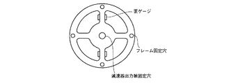
図4Aには、減速機の出力軸に取り付けられるトルク・センサの構成例を示している。図示のトルク・センサは、稀歪構造を有し、その微小変形量を梁部に対向して貼設した2対の歪みゲージA〜Dで計測する構成を備えている。図4Bには、トルク・センサの等価回路を示している。減速機の出力軸に印加されたトルク(外トルク)τeによって稀歪構造に変形が生じると、抵抗体A〜Dからなるブリッジ回路の両端にはτeにほぼ比例した電位差として計測される。かかるトルク計測結果は、アクチュエータ内に装備された制御用マイコンで収集された後、ホスト・コンピュータ(後述)に送信される。 Figure 4A shows a configuration example of a torque sensor attached to the output shaft of the reduction gear. The illustrated torque sensor has a rare strain structure, and has a configuration in which the minute deformation amount is measured by two pairs of strain gauges A to D attached to face the beam portion. FIG. 4B shows an equivalent circuit of the torque sensor. When deformation occurs in Mareibitsu structure by the applied torque to the output shaft of the reduction gear (outer torque) tau e, at both ends of the bridge circuit composed of the resistor A~D is measured as a potential difference which is substantially proportional to tau e . The torque measurement results are collected by a control microcomputer provided in the actuator and then transmitted to a host computer (described later).
図5には、図1に示した人間型ロボットにおける結線トポロジの構成例を示している。各関節駆動用のアクチュエータは、人間型ロボット全体の動作を統括的にコントロールするホスト・コンピュータと接続され、そのトルク制御目標値がホスト・コンピュータから与えられるとともに、現在の出力トルク、関節角度や関節角速度をホスト・コンピュータに送信することができる。 FIG. 5 shows a configuration example of the connection topology in the humanoid robot shown in FIG. Each joint drive actuator is connected to a host computer that comprehensively controls the operation of the entire humanoid robot, and its torque control target value is given from the host computer, and the current output torque, joint angle and joint Angular velocity can be sent to the host computer.
人間型ロボットは、胴体部に、3軸の腰関節アクチュエータa1、a2、a3、及び3軸の首関節アクチュエータa16、a17、a18を持ち、これらはホスト・コンピュータに対しシリアル接続されている。また、各アクチュエータ・モータa16、a17、a18の出力軸とフレームとの間には、図4に示したトルク・センサtq16、tq17、tq18が配置されている。各関節アクチュエータは、シリアル・ケーブルを通じて、その位置制御目標値を受け取るとともに、現在の出力トルクや関節角度、関節角速度をホスト・コンピュータに送信する。 The humanoid robot has three-axis hip joint actuators a1, a2, and a3 and three-axis neck joint actuators a16, a17, and a18 on the body, and these are serially connected to a host computer. Further, torque sensors tq16, tq17, and tq18 shown in FIG. 4 are arranged between the output shafts of the actuators and motors a16, a17, and a18 and the frame. Each joint actuator receives the position control target value via a serial cable and transmits the current output torque, joint angle, and joint angular velocity to the host computer.
また、人間型ロボットは、左腕部に、3軸の肩関節アクチュエータa4、a5、a6、1軸の肘関節アクチュエータa7、及び2軸の手首関節アクチュエータa8、a9を持ち、各アクチュエータ・モータa4、a5、a6、a7、a8、a9の出力軸とフレームとの間には、図4に示したトルク・センサtq4、tq5、tq6、tq7、tq8、tq9が配置され、これらはホスト・コンピュータに対しシリアル接続されている。同様に、人間型ロボットの右腕部には、3軸の肩関節アクチュエータa10、a11、a12、1軸の肘関節アクチュエータa13、及び2軸の手首関節アクチュエータa14、a15を持つとともに、各アクチュエータ・モータa10、a11、a12、a13、a14、a15の出力軸とフレームとの間には図4に示したトルク・センサtq10、tq11、tq12、tq13、tq14、tq15が配置され、これらはホスト・コンピュータに対しシリアル接続されている。 Further, the humanoid robot has three-axis shoulder joint actuators a4, a5, a6, a one-axis elbow joint actuator a7, and two-axis wrist joint actuators a8, a9 on the left arm portion, and each actuator / motor a4, Torque sensors tq4, tq5, tq6, tq7, tq8, and tq9 shown in FIG. 4 are arranged between the output shafts of a5, a6, a7, a8, and a9 and the frame. Serial connection. Similarly, the right arm portion of the humanoid robot has triaxial shoulder joint actuators a10, a11, a12, a monoaxial elbow joint actuator a13, and biaxial wrist joint actuators a14, a15, and each actuator / motor. Torque sensors tq10, tq11, tq12, tq13, tq14, and tq15 shown in FIG. 4 are arranged between the output shafts of a10, a11, a12, a13, a14, and a15 and the frame, and these are arranged on the host computer. For serial connection.
また、人間型ロボットは、左脚部に、3軸の股関節アクチュエータa19、a20、a21、1軸の膝関節アクチュエータa22、及び2軸の足首関節アクチュエータa23、a24を持つとともに、各アクチュエータ・モータa19、a20、a21、a22、a23、a24の出力軸とフレームとの間には図4に示したトルク・センサtq19、tq20、tq21tq22、tq23、tq24が配置され、これらはホスト・コンピュータに対しシリアル接続されている。同様に、右脚部には、3軸の肩関節アクチュエータa25、a26、a27、1軸の肘関節アクチュエータa28、及び2軸の足首関節アクチュエータa29、a30を持つとともに、各アクチュエータ・モータa25、a26、a27、a28、a29、a30の出力軸とフレームとの間には図4に示したトルク・センサtq25、tq26、tq27、tq28、tq29、tq30が配置され、これらはホスト・コンピュータに対しシリアル接続されている。 The humanoid robot has triaxial hip joint actuators a19, a20, a21, a monoaxial knee joint actuator a22, and biaxial ankle joint actuators a23, a24 on the left leg, and each actuator / motor a19. , A20, a21, a22, a23, a24 Torque sensors tq19, tq20, tq21 tq22, tq23, tq24 shown in FIG. 4 are arranged between the output shaft and the frame, and these are serially connected to the host computer. Has been. Similarly, the right leg has triaxial shoulder joint actuators a25, a26, a27, a monoaxial elbow joint actuator a28, and biaxial ankle joint actuators a29, a30, and each actuator motor a25, a26. Torque sensors tq25, tq26, tq27, tq28, tq29, and tq30 shown in FIG. 4 are arranged between the output shaft of a, a27, a28, a29, and a30 and the frame, and these are serially connected to the host computer. Has been.
ロボットのダイナミクス演算は、ホスト・コンピュータ上で実行され、各関節アクチュエータのトルク目標値を生成する。トルク目標値は、アクチュエータに併設された制御用マイコンに送信され、制御用マイコン上で実行されるアクチュエータの制御に用いられる。また、各関節アクチュエータは、力制御方式により制御される。 The robot dynamics calculation is executed on the host computer to generate a torque target value for each joint actuator. The torque target value is transmitted to a control microcomputer provided in the actuator, and is used for actuator control executed on the control microcomputer. Each joint actuator is controlled by a force control method.
ロボットのダイナミクスを考慮しながら機体の所定部位に所望の力を発生するための関節力を算出する方法によれば、力制御における外乱の影響を回避することができるが、誤差の主要因となる関節部の摩擦並びに慣性が理論モデルと合致するよう、理想的なアクチュエータを関節に用いることが必要となる。 According to the method of calculating the joint force for generating a desired force at a predetermined part of the airframe while taking into account the dynamics of the robot, the influence of disturbance in the force control can be avoided, but this is the main cause of error. It is necessary to use an ideal actuator for the joint so that the friction and inertia of the joint are consistent with the theoretical model.
ここで、関節アクチュエータがダイナミクス演算で用いられる理論モデルから逸脱した応答を行なうと、ダイナミクス演算により算出されたトルクをアクチュエータに作用させても、目的の運動状態は達成されない。実際、図4Aに示したような減速機を有したアクチュエータには、モデル化することができない未知の摩擦などのダイナミクスのパラメータが含まれており、力制御に影響を与える外乱の主要因となる。かかる外乱の問題に対し対策を施さなければ、容易に理論モデルから逸脱する。 Here, if the joint actuator makes a response deviating from the theoretical model used in the dynamics calculation, even if the torque calculated by the dynamics calculation is applied to the actuator, the target motion state is not achieved. In fact, the actuator having a reduction gear as shown in FIG. 4A, can not be modeled includes a parameter dynamics, such as unknown friction, the main cause of disturbance affecting force control . If no countermeasures are taken against the disturbance problem, it will easily deviate from the theoretical model.
そこで、本実施形態では、ロボットのダイナミクスを考慮しながら機体の所定部位に所望の力を発生するための関節力を算出する、という上記の第3の方法によって外乱の問題に対処するようにしている。このような場合、機体のいかなる部位にも6軸力センサを配設する必要はなくなる。 Therefore, in this embodiment, so as to deal with the disturbance problem by the third method for calculating, as the joint force for generating a desired force in a predetermined part of the aircraft, taking into account the dynamics of the robot Yes. In such a case, it is not necessary to provide a 6-axis force sensor at any part of the airframe.
以下では、摩擦や慣性といったモデル化できない外乱の影響を受けつつも、理論モデル通りの応答を行なうよう、アクチュエータの応答を矯正する方法について説明する。 Hereinafter, a method for correcting the response of the actuator so as to perform the response according to the theoretical model while being affected by disturbances that cannot be modeled such as friction and inertia will be described.
ロボットのダイナミクス演算において、アクチュエータは、下式(1)に示すような数式でモデル化される。 In the robot dynamics calculation, the actuator is modeled by a mathematical formula as shown in the following formula (1).
![]()
![]()
上式(1)において、Iaは関節の仮想イナーシャ、qは(エンコーダ出力として得られる)関節の関節角、τaは関節の発生トルクの指令値、τeは関節の作用する外トルク、νaは関節内部の(未知の、モデル化が困難となる)仮想的な粘性係数である。 In the above formula (1), I a is a virtual inertia of the joint, q is a joint angle of the joint (obtained as an encoder output), τ a is a command value of the generated torque of the joint, τ e is an external torque applied by the joint, ν a is a virtual viscosity coefficient (unknown and difficult to model) inside the joint.
上式(1)から、理論モデルには、関節に作用する外トルク項τeが含まれていることが分かる。したがって、アクチュエータの応答を理論モデル通りとなるように矯正するには、この外トルクτeを検出する必要がある。本実施形態では、図4を参照しながら説明したように、アクチュエータには、減速機の出力軸において外トルクτeを計測するためのトルク・センサが配設されており、そのトルク計測結果はマイコンで収集されるようになっている。 From the above equation (1), it can be seen that the theoretical model includes an external torque term τ e acting on the joint. Therefore, it is necessary to detect this external torque τ e in order to correct the actuator response so as to be in accordance with the theoretical model. In the present embodiment, as described with reference to FIG. 4, the actuator, the output shaft of the reduction gear and the torque sensor for measuring the external torque tau e is disposed, the torque measurement result It is collected by a microcomputer.
アクチュエータが上式(1)で表される理論モデルに従った応答を行なうことは、上式(1)の右辺が与えられたときに、左辺の関節角加速度が達成されることに他ならない。本実施形態では、このような関節角加速度制御系を構成するために、外乱トルクを推定する外乱オブザーバを適用することによって、理論応答モデルに基づいて関節トルクτを高い精度で決定するようにしている。 The actuator responding according to the theoretical model expressed by the above equation (1) is nothing but the achievement of the joint angular acceleration on the left side when the right side of the above equation (1) is given. In this embodiment, in order to configure such a joint angular acceleration control system, by applying a disturbance observer that estimates disturbance torque, the joint torque τ is determined with high accuracy based on a theoretical response model. Yes.
図6には、理論モデルに従った応答を行なうための関節角加速度制御系の制御ブロック図を示している。同図中で、点線で囲まれた部分が外乱オブザーバに相当し、外乱トルクτdを推定し、制御系に及ぼす影響を除去することによって、ロバストな加速度制御系を構築している。但し、Jnは関節内のイナーシャの公称値、Jは関節内のイナーシャの(未知の)実際値、qは関節角とする。また、関節の仮想イナーシャIaは、ダイナミクス演算における設計事項として仮想的な定数が与えられるとする。 FIG. 6 shows a control block diagram of a joint angular acceleration control system for performing a response according to a theoretical model. In the figure, a portion surrounded by a dotted line corresponds to a disturbance observer, and a robust acceleration control system is constructed by estimating the disturbance torque τ d and removing the influence on the control system. Where J n is the nominal value of the inertia in the joint, J is the (unknown) actual value of the inertia in the joint, and q is the joint angle. Further, it is assumed that a virtual constant is given to the joint virtual inertia Ia as a design item in the dynamics calculation.
ホスト・コンピュータ上では、制御周期毎に、力制御方式によりアクチュエータに対するトルク指令値τaを決定するとともに、アクチュエータの減速機出力軸に取り付けられたトルク・センサ(図4Bを参照のこと)によって計測された外トルク実測値τe、並びに減速機出力軸に取り付けられたエンコーダによって計測された関節角qから得られる角速度実測値がアクチュエータ内の制御用マイコンから送られてくる。そして、これらトルク指令値τa、外トルク実測値τe、並びに関節角qの角速度実測値を上式(1)で表される理論応答モデルに代入して、同式左辺の関節角qの加速度目標値を求め、この角加速度目標値を外乱オブザーバに投入する。 On the host computer, measured in each control cycle, and determines the torque command value tau a for the actuator by the force control method, the torque sensor attached to the output shaft for the reduction gear of the actuator (see FIG. 4B) It has an outer torque actual measurement value tau e, and the angular velocity actual measurement value obtained from the measured joint angle q by an encoder attached to the reduction gear output shaft is transmitted from the control microcomputer within the actuator. The torque command value τ a , the external torque actual measurement value τ e , and the angular velocity actual measurement value of the joint angle q are substituted into the theoretical response model expressed by the above equation (1), and the joint angle q An acceleration target value is obtained, and this angular acceleration target value is input to a disturbance observer.
外乱オブザーバ内では、入力された関節角qの加速度目標値に関節の仮想イナーシャ公称値Jnを掛けて、現制御周期におけるトルク目標値τrefに変換する。そして、外乱オブザーバにより前制御周期で得られた外乱トルクτdをこのトルク目標値τrefに修正を加えると、現制御周期における関節に対するトルク指令値τとなる。 In the disturbance observer, the input acceleration target value of the joint angle q is multiplied by the joint virtual inertia nominal value J n to convert it into a torque target value τ ref in the current control cycle. When the disturbance torque τ d obtained by the disturbance observer in the previous control cycle is corrected to this torque target value τ ref , the torque command value τ for the joint in the current control cycle is obtained.
伝達関数1/Jnからなる関節にトルク指令値τからなる力制御を掛けると、関節部に存在する摩擦や慣性などの外乱の影響を受けながら回転駆動する。具体的には、トルク指令値τを電流指令値に換算し、これがモータ・ドライバへの指示入力となる。その際の発生トルクτe並びに関節角qはそれぞれトルク・センサ並びにエンコーダでデ計測されるとともに、エンコーダ出力qを時間微分することで関節角速度が得られる。
When force control consisting of the torque command value τ is applied to the joint consisting of the
外乱オブザーバは、計測された関節角qの角速度に対し、関節の仮想イナーシャ公称値Jnからなる伝達関数Jnsを適用することで関節に作用したトルクを推定することができ、この推定トルクを関節へのトルク指令値τから引き算することで、外乱トルクτdを推定することができる。そして、現制御周期で得られた外乱トルクτdはフィードバックされ、次制御周期におけるトルク指令値τの修正に使用される(同上)。なお、途中に挿入された、g/(s+g)で表されるローパス・フィルタ(LPF)は、系の発散を防ぐためのものである。 The disturbance observer can estimate the torque acting on the joint by applying the transfer function J n s composed of the virtual joint nominal nominal value J n to the measured angular velocity of the joint angle q. Is subtracted from the torque command value τ to the joint, the disturbance torque τ d can be estimated. The disturbance torque τ d obtained in the current control cycle is fed back and used to correct the torque command value τ in the next control cycle (same as above). A low-pass filter (LPF) represented by g / (s + g) inserted in the middle is for preventing the divergence of the system.
このようにして、関節部に摩擦や慣性などのモデル化することができない外乱成分が存在していても、アクチュエータの加速度応答を加速度目標値に追従させることができる。すなわち、上式(1)の右辺が与えられたときに左辺の関節角加速度が達成されるので、アクチュエータは外乱の影響を受けるにも拘らず理論モデルに従った応答を実現することができる。但し、外乱トルクτdをフィードバックする途中に上記のローパス・フィルタg/(s+g)が挿入されており(前述)、高周波数域の外乱除去には向かない。 In this way, the acceleration response of the actuator can be made to follow the acceleration target value even if there are disturbance components such as friction and inertia that cannot be modeled in the joint. That is, since the joint angular acceleration on the left side is achieved when the right side of the above equation (1) is given, the actuator can realize a response according to the theoretical model despite being affected by the disturbance. However, the low-pass filter g / (s + g) is inserted in the middle of feeding back the disturbance torque τ d (described above), and is not suitable for removing disturbances in the high frequency range.
なお、外乱オブザーバについては、例えば、「外乱オブザーバによるロバスト・モーションコントロール」((非特許文献1)を参照されたい。外乱オブザーバは、プラント内の外乱成分を推定し、制御入力にフィードバックすることで、プラントに未知のパラメータ変動や外乱があっても、目標状態に到達させる効力がある。但し、正しく外乱を推定するには、複数のサイクルに亘ってフィードバック演算を繰り返す必要がある。 For the disturbance observer, see, for example, “Robust Motion Control by Disturbance Observer” (Non-Patent Document 1). The disturbance observer estimates the disturbance component in the plant and feeds it back to the control input. Even if there are unknown parameter fluctuations and disturbances in the plant, it is effective to reach the target state, but it is necessary to repeat the feedback calculation over a plurality of cycles in order to correctly estimate the disturbances.
図6に示した制御ブロック構成では、外乱オブザーバは、関節角qの角加速度を上式(1)によって求め、これを関節アクチュエータに対する関節角加速度目標値に設定する。関節角qの角加速度は、減速機の出力軸に取り付けられたトルク・センサから得られた外トルクτeと、関節の発生トルクτaと、減速木の出力軸に取り付けられたエンコーダから出力される関節角qの時間微分を基に決定される。このような構成をとることによって、関節は、ユーザが指定したイナーシャIa及び粘性係数νaに従った応答を行なうことが可能となり、理想化若しくは仮想化される。 In the control block configuration shown in FIG. 6, the disturbance observer obtains the angular acceleration of the joint angle q by the above equation (1), and sets this as the joint angular acceleration target value for the joint actuator. Angular acceleration of the joint angle q is output and an outer torque tau e obtained from the torque sensor attached to the output shaft of the reduction gear, a torque tau a of the joint, from an encoder attached to the output shaft of the reduction tree It is determined based on the time derivative of the joint angle q. By adopting such a configuration, the joint can respond in accordance with the inertia I a and the viscosity coefficient ν a specified by the user, and is idealized or virtualized.
図7には、ユーザが指定したイナーシャIa及び粘性係数νaにより数値計算して得られた関節角の理論応答と、図6に示した制御系を適用した関節角の実測応答の比較を示している。但し、関節角の実測は、大きな摩擦を有する波動歯車装置にトルク・センサを取り付けたアクチュエータに対して図6に示した制御系を適用して行なった。 FIG. 7 shows a comparison between the theoretical response of the joint angle obtained by numerical calculation using the inertia I a and the viscosity coefficient ν a specified by the user, and the measured response of the joint angle to which the control system shown in FIG. 6 is applied. Show. However, the actual measurement of the joint angle was performed by applying the control system shown in FIG. 6 to an actuator in which a torque sensor was attached to a wave gear device having a large friction.
図7に示した比較結果によれば、図6に示した制御系を適用した場合の実測応答は、理論応答とほぼ合致することが分かる。したがって、図6に示した制御系を適用することで、関節部に摩擦や慣性などの未知の外乱成分が含まれていても、所望の理想的な応答を行なう(すなわち仮想化された)アクチュエータとして矯正できる、と言うことができる。 According to the comparison result shown in FIG. 7, it can be seen that the measured response when the control system shown in FIG. 6 is applied substantially matches the theoretical response. Therefore, by applying the control system shown in FIG. 6, an actuator that performs a desired ideal response (that is, virtualized) even if an unknown disturbance component such as friction or inertia is included in the joint. It can be said that it can be corrected.
図6に示したような、外乱オブザーバを用いた制御システムにより理想的な関節角加速度応答を実現するためのアクチュエータ制御は、比較的簡素な処理演算で構成することができ、例えば各アクチュエータに併設された制御用マイコン上でそれぞれ独立して高サンプリングレート(例えば、100マイクロ秒周期)で実行することが可能である。 Actuator control for realizing an ideal joint angular acceleration response by a control system using a disturbance observer as shown in FIG. 6 can be configured by a relatively simple processing operation. Each of the control microcomputers can be independently executed at a high sampling rate (for example, a cycle of 100 microseconds).
図8には、理想的な関節角加速度応答を実現する演算の処理手順をフローチャートの形式で示している。 FIG. 8 shows a processing procedure for realizing an ideal joint angular acceleration response in the form of a flowchart.
まず、アクチュエータの減速機出力軸に取り付けたトルク・センサの値を計測し、外トルクτeを得る(ステップS1)。 First, the value of the torque sensor attached to the reduction gear output shaft of the actuator is measured to obtain the external torque τ e (step S1).
次いで、アクチュエータの減速機出力軸に取り付けたエンコーダの値を計測して、関節角qを得る(ステップS2)。さらに、この関節角qを時間微分して関節角速度を得る。 Next, the value of the encoder attached to the reduction gear output shaft of the actuator is measured to obtain the joint angle q (step S2). Further, the joint angular velocity is obtained by differentiating the joint angle q with respect to time.
次いで、上式(1)を用いて、関節角qの関節角加速度目標値を算出する(ステップS3)。すなわち、下式(2)の計算を行なう。 Next, the joint angular acceleration target value of the joint angle q is calculated using the above equation (1) (step S3). That is, the following equation (2) is calculated.
![]()
![]()
次いで、外乱オブザーバにより外乱トルクτdを得る(ステップS4)。図6より、外乱トルクτdは下式(3)により算出される。但し、同式中のトルク指令値τは前制御周期のものとする。 Next, a disturbance torque τ d is obtained by a disturbance observer (step S4). From FIG. 6, the disturbance torque τ d is calculated by the following equation (3). However, the torque command value τ in the equation is assumed to be in the previous control cycle.

ステップS2において上式(2)から得られた関節角加速度をトルク目標値τrefに変換し、このトルク目標値τrefから上式(3)により得られた外乱トルクτdを加算することで、現制御周期のトルク指令値τを求めることができる。 Convert the joint angle acceleration obtained from the above equation (2) to the torque target value tau ref at step S2, by adding the disturbance torque tau d obtained by the above equation (3) from the torque target value tau ref The torque command value τ for the current control cycle can be obtained.
![]()
![]()
次いで、上式(4)から得られたトルク指令値τをトルク定数Ktで割ることによって、モータ・ドライバへの電流指令値irefを算出する(ステップS5)。 Next, the current command value i ref to the motor driver is calculated by dividing the torque command value τ obtained from the above equation (4) by the torque constant K t (step S5).
![]()
![]()
そして、得られた電流指令値irefをモータ・ドライバへ送出し、電流制御を実行する(ステップS6)。 Then, the obtained current command value i ref is sent to the motor driver, and current control is executed (step S6).
例えば、本出願人に既に譲渡されている特開2007−108955号公報には、ダイナミクス演算を応用してロボットの力制御を行なう方法について開示されている。上述したような理想化されたアクチュエータが達成されると、ダイナミクス演算を用いたロボットの力制御を好適に実現することができる。 For example, Japanese Patent Application Laid-Open No. 2007-108955 already assigned to the present applicant discloses a method for controlling the force of a robot by applying dynamics calculation. When the idealized actuator as described above is achieved, it is possible to suitably realize the force control of the robot using the dynamics calculation.
図2に示した関節自由度モデルは、2足歩行の移動ロボットを、骨盤Bを基底とする開リンク木構造として表現している。ロボットは、ワールド空間中を自由に移動し、姿勢を変化させることができる。そこで、ロボット全体の状態を表すための状態変数として、骨盤Bのオイラー角α=(α,β,γ)Tとその位置p0(p0x,p0y,p0z)Tを導入する。すると、ロボット全体の姿勢を表す一般化変数qは、アクチュエータの現在状態としての全関節値を並べてできるベクトルθと、ロボットの運動状態としてのベースの姿勢α及び位置p0を並べたベクトルとして、下式(6)のような形で表現することができる。 The joint degree-of-freedom model shown in FIG. 2 represents a biped walking mobile robot as an open link tree structure based on the pelvis B. The robot can move freely in the world space and change its posture. Therefore, the Euler angles α = (α, β, γ) T of the pelvis B and their positions p 0 (p 0x , p 0y , p 0z ) T are introduced as state variables for representing the state of the entire robot. Then, the generalized variable q representing the posture of the entire robot is a vector θ in which all joint values as the current state of the actuator are arranged, and a vector in which the base posture α and the position p 0 as the robot motion state are arranged, It can be expressed in the form of the following formula (6).
![]()
![]()
力制御系のロボット制御における重要な概念として、「操作空間(Operational Space)」と呼ばれる概念がある。操作空間は、ロボットに作用する力と発生する加速度の関係を記述するための空間である。ロボットの関節角を位置制御ではなく力制御する際にロボットと環境の接し方を拘束条件として用いるときに、操作空間が必須となる。剛体リンクが関節を介して連なったリンク構造物において、関節の値をすべて連ねてできるベクトルを一般化変数と呼び、qで表すものとする。一般化変数qの時間微分値との関係がヤコビアンJを用いて、下式(7)に示す形に関連付けるとき、物理量xに対して操作空間を定義することができる。 An important concept in the robot control of the force control system is a concept called “operational space”. The operation space is a space for describing the relationship between the force acting on the robot and the generated acceleration. When the robot joint angle is controlled by force rather than position control, an operation space is indispensable when the contact between the robot and the environment is used as a constraint condition. In a link structure in which rigid links are connected via joints, a vector that is formed by connecting all joint values is called a generalized variable, and is represented by q. When the relationship between the generalized variable q and the time differential value is related to the form shown in the following equation (7) using Jacobian J, an operation space can be defined for the physical quantity x.
![]()
![]()
マニピュレータ先端の手先位置姿勢など、タスク遂行のためのデカルト座標系が操作空間の一例である。操作空間の基本的な考え方については、例えば、“A unified approach to motion and force control of robot manipulators”(The operational space formulation,IEEE Journal of Robotics and Automation,RA−3(1),pp.43−53,1987)を参照されたい。 A Cartesian coordinate system for performing tasks, such as the hand position and orientation at the tip of the manipulator, is an example of the operation space. For the basic concept of the operation space, see, for example, “A unified applied to motion and force control of robot-manipulators” (The operational space of R & D 3). 1987).
一般に、リンク構造物全体の運動方程式は、下式(8)に示すような形で表現できることが知られている。 In general, it is known that the equation of motion of the entire link structure can be expressed in the form shown in the following equation (8).
![]()
![]()
ここで、τは一般化変数qに対応した一般化力、bは重力・コリオリ力、fは操作空間に作用する外力である。上式(8)を下式(9)のように変形する。 Here, τ is a generalized force corresponding to the generalized variable q, b is a gravity / Coriolis force, and f is an external force acting on the operation space. The above equation (8) is transformed into the following equation (9).
![]()
![]()
ここで、Λ-1は操作空間慣性逆行列と呼ばれ、下式(10)のように表される。但し、Hは構造全体の関節空間に対する慣性行列である。 Here, Λ −1 is called an operation space inertia inverse matrix and is expressed as the following equation (10). However, H is an inertia matrix with respect to the joint space of the whole structure.
![]()
![]()
また、上式(9)の右辺第3項のcは操作空間バイアス加速度(すなわち、外力が作用しない場合に操作空間に作用する加速度)に相当し、下式(11)のように表される。 Further, c in the third term on the right side of the above equation (9) corresponds to the operation space bias acceleration (that is, the acceleration acting on the operation space when no external force is applied), and is represented by the following equation (11). .
![]()
![]()
操作空間、すなわち加速度と力の関係は操作空間慣性逆行列によって与えられる。なお、上式(10)に示した定義通りの計算では、構造全体の関節空間に対する慣性行列Hが介在して計算の無駄が発生するために、操作空間慣性逆行列の算出には非常に多くの計算量となるため、実時間処理に向かないという問題がある。これに対し、リンク構造物の一般化力(関節力)から一般化加速度(関節加速度)を得るダイナミクス演算を応用することで、操作空間慣性逆行列を高速に算出するとともに計算負荷の軽減を図ることができる。操作空間慣性逆行列及びバイアス加速度の高速な計算方法に関しては、例えば本出願人に既に譲渡されている特開2007−108955号公報を参照されたい。 The operation space, that is, the relationship between acceleration and force is given by the operation space inertia inverse matrix. In the calculation as defined in the above equation (10), the inertia matrix H with respect to the joint space of the entire structure is interposed, so that the calculation is wasted. Therefore, there is a problem that it is not suitable for real-time processing. On the other hand, by applying dynamics calculation that obtains generalized acceleration (joint acceleration) from the generalized force (joint force) of the link structure, the operation space inertia inverse matrix is calculated at high speed and the calculation load is reduced. be able to. For a high-speed calculation method of the operation space inertia inverse matrix and the bias acceleration, see, for example, Japanese Patent Application Laid-Open No. 2007-108955 already assigned to the present applicant.
ダイナミクス演算を用いたロボットの制御方法では、多様な運動目的を達成するために、第1段階として操作空間に作用する仮想的な力fを求め、第2段階として仮想的な力fを実在する関節トルクと環境からの外力に変換する、という2段階解放を取ることができる(例えば、本出願人に既に譲渡されている特願2007−272099号明細書を参照されたい)。 In the robot control method using the dynamics calculation, in order to achieve various motion objectives, a virtual force f acting on the operation space is obtained as the first step, and the virtual force f exists as the second step. It is possible to take a two-stage release of converting into joint torque and external force from the environment (see, for example, Japanese Patent Application No. 2007-272099 already assigned to the present applicant).
第1段階として、操作空間に印加すべき仮想力fは、下式(12)及び(13)に示すような線形相補性問題を解くことで得ることができる。 As a first step, the virtual force f to be applied to the operation space can be obtained by solving the linear complementarity problem as shown in the following equations (12) and (13).
![]()
![]()
![]()
![]()
また、力に関する運動要求として、既知の力fkを操作空間Jkに発生する要求があるものとすると、上記の位置・速度・加速度に関する運動要求と併せて、全体で要求される仮想力すなわち一般化力τvは下式(14)のように表される。 Assuming that there is a request for generating a known force f k in the operation space J k as a motion request related to the force, in addition to the motion request related to the position / velocity / acceleration described above, The generalized force τ v is expressed as the following formula (14).
![]()
![]()
但し、fvはfとfkの連結ベクトルであり、JvはJとJkを縦に並べてできるfvの操作空間を表すヤコビアンである。 Here, f v is a concatenated vector of f and f k , and J v is a Jacobian representing an operation space of f v in which J and J k are vertically arranged.
第2段階では、下式(15)に示すように、仮想力fvを環境から得られる外力feと、関節部のアクチュエータのトルクτaに変換する。fvは実在しない力も含む仮想力である。 In the second stage, as shown in the following equation (15), the virtual force f v is converted into an external force fe obtained from the environment and a torque τ a of the joint actuator. f v is a virtual force including a force that does not exist.
![]()
![]()
ここで、Je、Jaは、fe、τaの作用する操作空間に対応するヤコビアンである。 Here, J e and J a are Jacobians corresponding to the operation space in which f e and τ a act.
式(15)を満足するfe及びτaが常に存在するとは限らない。そこで、上式仮想力fvの修正分Δfvを考慮する。 There are not always f e and τ a that satisfy Equation (15). So, consider the correction amount Δf v in the above equation virtual force f v.
![]()
![]()
上式(16)は、下式(17)及び(18)のような問題を解くことで、解を得ることができる。 The above equation (16) can be obtained by solving problems such as the following equations (17) and (18).
![]()
![]()
ここで、eは、上式(16)の左辺から右辺を引いた値であり、上式(16)の誤差を与える。また、yは、τa、fe、Δfvの連結ベクトルである。よって、上式(17)の 第1項は、上式(16)の等式成立の誤差最小化のための条件を、上式(18)の第2項は、仮想力修正量Δfv、実在力fe及びτaの最小化のための条件を表している。Q1並びにQ2はそれらの間の最小化の重みを表す正定値対称行列である。不等式拘束式(18)は、垂直反力、摩擦条件、関節発生力の上限・下限などを与える。 Here, e is a value obtained by subtracting the right side from the left side of the above equation (16), and gives an error of the above equation (16). Y is a connected vector of τ a , f e , and Δf v . Therefore, the first term of the above equation (17) is the condition for minimizing the error in establishing the equation of the above equation (16), and the second term of the above equation (18) is the virtual force correction amount Δf v , it represents a condition for minimization of actual force f e and tau a. Q 1 and Q 2 are positive definite symmetric matrices representing the minimization weights between them. The inequality constraint formula (18) gives the vertical reaction force, the friction condition, the upper and lower limits of the joint generation force, and the like.
上式(17)及び(18)を整理すると、下式(19)及び(20)に示すような2次計画問題として定式化される。 If the above formulas (17) and (18) are arranged, they are formulated as secondary planning problems as shown in the following formulas (19) and (20).
![]()
![]()
2次計画問題を用いることで、上式(19)及び(20)をy、ひいてはτa、fe、Δfvについて解くことができる。これを解いて得られる関節部のアクチュエータのトルクτaをロボットに作用すれば良い。 By using the quadratic programming problem, the above equations (19) and (20) can be solved for y, and thus τ a , f e , and Δf v . The torque τ a of the joint actuator obtained by solving this may be applied to the robot.
上述したようなダイナミクス演算に基づく力制御方式によれば,6軸力センサの値は必要としない。但し、ここで得られたτa は、一般のアクチュエータに適用しても、未知の摩擦などの誤差が存在し、所望の値を達成できない。また、その応答特性も上記ダイナミクス演算で用いる理想的な関節モデル(上式(1))から逸脱し、運動目的は達成され難しい。これに対し、本発明が提供する理想応答可能なアクチュエータを用いる場合には、ダイナミクス演算が前提とした通りの関節応答が可能となり、ひいては、ロボット全体の運動目的も良好に達成可能となる。 According to the force control method based on the dynamics calculation as described above, the value of the 6-axis force sensor is not required. However, τ a obtained here cannot be achieved at a desired value because of errors such as unknown friction even if it is applied to a general actuator. Further, the response characteristic deviates from the ideal joint model (the above formula (1)) used in the dynamics calculation, and the exercise purpose is difficult to achieve. On the other hand, when the actuator capable of ideal response provided by the present invention is used, the joint response as assumed in the dynamics calculation can be achieved, and as a result, the motion purpose of the entire robot can be satisfactorily achieved.
なお、上述した演算は、アクチュエータの理想化のための制御演算よりも低サンプリングレートで実行する。例えば、1ミリ秒周期で実行するものとする。 The calculation described above is executed at a lower sampling rate than the control calculation for the idealization of the actuator. For example, it is assumed that it is executed at a cycle of 1 millisecond.
また、上述した実施形態では、外乱オブザーバ内部で必要となる関節角加速度を得るために、数値微分並びにローパス・フィルタを用いたが、これはアクチュエータの応答を低下させる要因となる。関節角加速度を直接的に計測するため、アクチュエータに加速度検出手段を直接設けてもよい。 In the above-described embodiment, the numerical differentiation and the low-pass filter are used to obtain the joint angular acceleration required inside the disturbance observer, but this causes a decrease in the response of the actuator. In order to directly measure the joint angular acceleration, the actuator may be directly provided with acceleration detecting means.
図9には、ダイナミクス演算に基づく力制御方式によるロボットの制御システム10の機能ブロック図を示している。
FIG. 9 shows a functional block diagram of a
力学モデル11は、制御対象となるロボットの剛体リンクの幾何学的パラメータ、動力学的パラメータを保持する。関節角度など、現在のロボットの状態に応じて時々刻々と変化するものも、力学モデル11が保持するデータに含まれる。 The dynamic model 11 holds geometric parameters and dynamic parameters of a rigid link of a robot to be controlled. Data that changes every moment depending on the current state of the robot, such as the joint angle, is also included in the data held by the dynamic model 11.
目標値設定部12は、ロボットの各部位、関節、運動量に課される、位置・速度・加速度・姿勢・角速度・角加速度・力・モーメントなどに関する目標値を設定する。例えば、位置・速度・加速度・姿勢・角速度・角加速度については、上式(9)の左辺の値として目標値が設定される。既知の力fkについては別途記憶しておく。 The target value setting unit 12 sets target values related to position, velocity, acceleration, posture, angular velocity, angular acceleration, force, moment, and the like imposed on each part, joint, and momentum of the robot. For example, for position, velocity, acceleration, posture, angular velocity, and angular acceleration, a target value is set as the value on the left side of equation (9). The known force f k is stored separately.
仮想的外力算出部13は、目標値設定部12で設定された目標値を実現するために必要な仮想的外力を求める。具体的には、未知の仮想的外力については、上式(12)及び(13)を満足する力fを線形相補性問題解決器13−2によって求める。上式(12)の係数行列Λ-1やバイアス・ベクトルcは、操作空間物理量算出部13−1において、操作空間物理量の高速演算(例えば、特開2007−108955号公報を参照のこと) を用いて求める。操作空間物理量の算出に、力学モデルの情報が利用される。既知の仮想的外力fkがさらに付加される場合は、全体で要求される仮想的外力は式(14)で得る。 The virtual external force calculation unit 13 obtains a virtual external force necessary for realizing the target value set by the target value setting unit 12. Specifically, for an unknown virtual external force, a force f satisfying the above equations (12) and (13) is obtained by the linear complementarity problem solver 13-2. The coefficient matrix Λ −1 and the bias vector c in the above equation (12) are subjected to high-speed operation space physical quantity calculation (see, for example, Japanese Patent Application Laid-Open No. 2007-108955) in the operation space physical quantity calculation unit 13-1. Use to find. The information of the dynamic model is used for calculation of the operation space physical quantity. When the known virtual external force f k is further added, the virtual external force required as a whole is obtained by Expression (14).
実在力変換部15は、仮想的外力算出部13で得られた仮想的外力τv=JT vfv を、上式(16)を満足するように、実在力、すなわち、環境から得られる外力feと、関節部のアクチュエータのトルクτaに変換する。仮想的外力から実在力への変換処理は、2次計画問題解決器15−1で上式(19)及び(20)を解くことで達成される。実在力変換部15は、そのうち、アクチュエータのトルクτaを出力する。 The real force conversion unit 15 obtains the virtual external force τ v = J T v f v obtained by the virtual external force calculation unit 13 from the real force, that is, the environment so as to satisfy the above equation (16). The external force f e and the torque τ a of the joint actuator are converted. The conversion process from the virtual external force to the real force is achieved by solving the above equations (19) and (20) by the secondary programming problem solver 15-1. The real force conversion unit 15 outputs the torque τ a of the actuator among them.
トルク検出手段16は、関節部に取り付けられたトルク・センサ(図4Aを参照のこと)であり、各関節部に作用する実トルクを計測し、出力する。そして、トルク・フィードバック制御部17は、トルク検出部16で検出されたトルクと、指令トルクの偏差を検出し、電流目標値にフィードバックする。これにより、モータ駆動系に含まれる摩擦や慣性などの外乱を抑圧し、精度良くアクチュエータ目標トルクが各関節において実現される。
The torque detection means 16 is a torque sensor (see FIG. 4A) attached to the joints, and measures and outputs the actual torque acting on each joint. Then, the torque /
以上、特定の実施形態を参照しながら、本発明について詳解してきた。しかしながら、本発明の要旨を逸脱しない範囲で当業者が該実施形態の修正や代用を成し得ることは自明である。 The present invention has been described in detail above with reference to specific embodiments. However, it is obvious that those skilled in the art can make modifications and substitutions of the embodiment without departing from the gist of the present invention.
本明細書では、本発明を2足歩行の脚式移動ロボットに適用した実施形態を中心に説明してきたが、本発明の要旨はこれに限定されるものではない。関節アクチュエータを力制御方式で動作させる多リンク構造体からなるさまざまなタイプのメカトロ機器に対して、同様に本発明を適用することができる。 In the present specification, the embodiment in which the present invention is applied to a bipedal legged mobile robot has been mainly described, but the gist of the present invention is not limited to this. The present invention can be similarly applied to various types of mechatronics devices composed of a multi-link structure that operates a joint actuator by a force control method.
要するに、例示という形態で本発明を開示してきたのであり、本明細書の記載内容を限定的に解釈するべきではない。本発明の要旨を判断するためには、特許請求の範囲を参酌すべきである。 In short, the present invention has been disclosed in the form of exemplification, and the description of the present specification should not be interpreted in a limited manner. In order to determine the gist of the present invention, the claims should be taken into consideration.
なお、上記実施形態に開示した本発明は意匠の創作としても捉えられ、図1A〜Fとして示した人間型ロボットは、意匠法施行規則別表1と同程度の物品の区分でいうところの「ロボットおもちゃ」に相当し、当該意匠に係る物品の説明として次の捉え方もできる。 Note that the present invention disclosed in the above embodiment is also regarded as a creation of a design, and the humanoid robot shown in FIGS. 1A to 1F is a “robot” in the same category of articles as the Design Act Enforcement Regulations Attached Table 1. It corresponds to a “toy” and can be understood as the following description of an article related to the design.
当該意匠に係る物品は、その行動及び思考、例えば歩行等が自立的に制御された人間型のロボットであって、人間と同様に、手指、手足を動かし、首を動かし、腰を動かすことができる。当該物品は、産業上の特定の用途に供されることを目的とした従来型の産業用ロボットと異なり、特段斯かる産業上の限定的な用途を有しない。また、従来型の玩具や人形の類とも異なり、単なる遊び道具ではない。その主眼は、恰も実際の人間の如く、人間と自律的に意思、感情、思考を交流(コミュニケート)し、人間の生活を潤わせ、そして此れを補助することにある。如何なる用途、目的に供するかは、これを使用する者次第であり、例えば子供の遊び相手として主に愛玩の用に用いることもでき、或いは病人の看護の目的に供することもでき、更には、悪環境における作業を人間に代替させることも可能である。斯かる意味において、当該物品は、用途及び機能を特定することにより定義される、従来型の物品とは異なるものである。 Articles related to the design are humanoid robots whose behavior and thoughts, such as walking, are controlled autonomously, and can move fingers, limbs, move the neck, move the waist in the same way as humans. it can. Unlike the conventional industrial robot intended to be used for a specific industrial application, the article does not have such a limited industrial application. Unlike traditional toys and dolls, it is not just a play tool. Its main objective is to communicate with human beings autonomously, communicate and communicate with each other like a real human being, to improve and assist human life. Depending on the person who uses this, it can be used mainly for pets as a child's play partner, or for the purpose of nursing a sick person. It is also possible to substitute humans for work in adverse environments. In that sense, the article is different from a conventional article defined by specifying the application and function.
また、図1G〜Lとして示したロボットの頭部については、意匠法施行規則別表1と同程度の物品の区分でいうところの「ロボットおもちゃ」を構成する交換可能な部品としても捉えられ、「ロボットおもちゃ用頭部」に相当する。当該意匠に係る物品の説明については、頭部が交換可能であるという機能的な説明を除き、その用途は「ロボットおもちゃ」であって上記段落番号0129に記載した内容と共通するため省略する。
Further, the robot head shown in FIGS. 1G to 1L can also be regarded as a replaceable part that constitutes a “robot toy” in the same category of articles as the
ここで、上記実施形態に開示した本発明は意匠の創作としても捉えた場合にける意匠の説明を追記するが、図1Bは右側面図であるところ、左側面図は略対称に表れることから図示を省略している。同様に、図1Hに対して左側面図は略対称に表れることから図示を省略している。 Here, the present invention disclosed in the above embodiment adds a description of the design when it is also regarded as a creation of the design. However, FIG. 1B is a right side view, and the left side view appears substantially symmetrically. The illustration is omitted. Similarly, since the left side view appears substantially symmetrical with respect to FIG. 1H, the illustration is omitted.
さらに、図1A〜Lからは、上記実施形態に開示した本発明を部分意匠として捉えられることができるものとする。けだし、敢えて図示をせずとも、当該意匠に係る物品を「ロボットおもちゃ」とし、当該「ロボットおもちゃ」に係る部分意匠としては、図1G〜Lで示した部位を部分意匠として意匠登録を受けようとすることが推認でき、当該部分意匠として意匠登録を受けようとする部分以外の部分については図1A〜Fのうち当該図1G〜Lを差し引くことで推認可能だからである。 Furthermore, from FIGS. 1A to L, the present invention disclosed in the above embodiment can be regarded as a partial design. However, even if not intentionally illustrated, the article related to the design is a “robot toy”, and the partial design related to the “robot toy” will receive the design registration with the part shown in FIGS. 1G to L as the partial design. This is because it can be inferred by subtracting FIGS. 1G to 1L of FIGS. 1A to 1F for parts other than the part to be subjected to design registration as the partial design.
10…制御システム
11…力学モデル
12…目標設定部
13…仮想的外力算出部
13−1…操作空間物理量算出部
13−2…線形相補性問題解決器
15…実在力変換部
15−1…2次計画問題解決器
16…トルク検出手段
17…トルク・フィードバック制御部
DESCRIPTION OF
Claims (10)
前記減速機の出力段における関節値qを検出する関節値検出手段と、
前記減速機の出力段における関節駆動方向の作用力τeを検出する作用力検出手段と、
前記アクチュエータへの指示トルクτを決定するトルク決定手段と、
を具備し、
前記トルク決定手段は、
前記トルク決定手段が決定した指示トルクτにて前記アクチュエータを駆動した際の外乱トルクτdを算出する外乱オブザーバを備え、
前記トルク指令値τaと、前記作用力τeと、前記関節値qを時間微分して得られる関節値速度に基づいて前記アクチュエータが応答したことにより達成される関節値加速度目標値を求めて出力するアクチュエータの理論応答モデルから得られる関節値加速度目標値に関節内のイナーシャの公称値Jnを掛けたトルク目標値τrefを、前制御周期において前記外乱オブザーバによって得られた外乱トルクτdで修正して、現制御周期における指示トルクτを決定する、
ことを特徴とするアクチュエータ制御装置。 For force-controlling a joint driving actuator having a motor that generates rotational torque, a motor driver that drives the motor, and a speed reducer that converts the rotational speed of the motor according to the commanded torque command value τ a An actuator control device comprising:
Joint value detecting means for detecting a joint value q at the output stage of the speed reducer;
Acting force detecting means for detecting an acting force τ e in the joint driving direction at the output stage of the speed reducer;
Torque determining means for determining an instruction torque τ to the actuator;
Comprising
The torque determining means includes
A disturbance observer for calculating a disturbance torque τ d when the actuator is driven with the indicated torque τ determined by the torque determining means;
Obtaining a joint value acceleration target value achieved by the response of the actuator based on a joint value speed obtained by time differentiation of the torque command value τ a , the acting force τ e, and the joint value q The torque target value τ ref obtained by multiplying the joint value acceleration target value obtained from the theoretical response model of the actuator to be output by the nominal value J n of the inertia in the joint is used as the disturbance torque τ d obtained by the disturbance observer in the previous control period. To correct the command torque τ in the current control cycle,
An actuator control device.
ことを特徴とする請求項1に記載のアクチュエータ制御装置。 The theoretical response model of the actuator is a virtual viscosity obtained by multiplying a joint value speed obtained by time differentiation of the acting force τ e and the joint value q from the torque command value τ a by a virtual viscosity coefficient ν a inside the joint. From the result of subtracting the resistance force, the torque command value τ a , the action force τ e, and the equation are used to obtain a value obtained by multiplying the joint virtual acceleration I a by the joint value acceleration target value. Obtaining and outputting a joint value acceleration target value achieved by the response of the actuator based on a joint value speed obtained by differentiating the joint value q with respect to time;
The actuator control apparatus according to claim 1.
ことを特徴とする請求項1に記載のアクチュエータ制御装置。 The disturbance observer is based on a joint value speed obtained by time-differentiating a joint value q detected by the joint value detection unit when the actuator is driven with an instruction torque τ determined by the torque determination unit. Estimating the torque acting on the joint and calculating the disturbance torque τ d by subtracting the estimated torque from the command torque τ,
The actuator control apparatus according to claim 1.
前記減速機の出力段における関節値qを取得する関節値取得ステップと、
前記減速機の出力段における関節駆動方向の作用力τeを取得する作用力取得ステップと、
前記アクチュエータへの指示トルクτを決定するトルク決定ステップと、
を有し、
前記トルク決定ステップでは、
外乱オブザーバを適用して、前記トルク決定ステップにおいて決定した指示トルクτにて前記アクチュエータを駆動した際の外乱トルクτdを算出し、
前記トルク指令値τaと、前記作用力τeと、前記関節値qを時間微分して得られる関節値速度に基づいて前記アクチュエータが応答したことにより達成される関節値加速度目標値を求めて出力するアクチュエータの理論応答モデルから得られる関節値加速度目標値に関節内のイナーシャの公称値Jnを掛けたトルク目標値τrefを、前制御周期において前記外乱オブザーバによって得られた外乱トルクτdで修正して、現制御周期における指示トルクτを決定する、
ことを特徴とするアクチュエータ制御方法。 For force-controlling a joint driving actuator having a motor that generates rotational torque, a motor driver that drives the motor, and a speed reducer that converts the rotational speed of the motor according to the commanded torque command value τ a An actuator control method comprising:
A joint value acquisition step of acquiring a joint value q in the output stage of the speed reducer;
An action force acquisition step of acquiring an action force τ e in the joint drive direction at the output stage of the speed reducer;
A torque determining step for determining an instruction torque τ to the actuator;
Have
In the torque determination step,
Applying a disturbance observer to calculate a disturbance torque τ d when the actuator is driven with the indicated torque τ determined in the torque determination step,
Obtaining a joint value acceleration target value achieved by the response of the actuator based on a joint value speed obtained by time differentiation of the torque command value τ a , the acting force τ e, and the joint value q The torque target value τ ref obtained by multiplying the joint value acceleration target value obtained from the theoretical response model of the actuator to be output by the nominal value J n of the inertia in the joint is used as the disturbance torque τ obtained by the disturbance observer in the previous control period. Correct with d to determine the command torque τ in the current control cycle,
An actuator control method characterized by the above.
ことを特徴とする請求項4に記載のアクチュエータ制御方法。 The theoretical response model of the actuator is a virtual viscosity obtained by multiplying a joint value speed obtained by time differentiation of the acting force τ e and the joint value q from the torque command value τ a by a virtual viscosity coefficient ν a inside the joint. From the result of subtracting the resistance force, the torque command value τ a , the action force τ e, and the equation are used to obtain a value obtained by multiplying the joint virtual acceleration I a by the joint value acceleration target value. Obtaining and outputting a joint value acceleration target value achieved by the response of the actuator based on a joint value speed obtained by differentiating the joint value q with respect to time;
The actuator control method according to claim 4, wherein:
ことを特徴とする請求項4に記載のアクチュエータ制御方法。 The disturbance observer, when driving the actuator with the command torque τ determined in the torque determination step, based on the joint value speed obtained by time differentiation of the joint value q acquired in the joint value acquisition step Estimating the torque acting on the joint and calculating the disturbance torque τ d by subtracting the estimated torque from the command torque τ,
The actuator control method according to claim 4, wherein:
回転トルクを発生するモータと、
前記モータを駆動するモータ・ドライバと、
前記モータの回転速度を変換する減速機と、
前記減速機の出力軸における関節角qを計測するエンコーダと、
前記減速機の出力軸に作用する外トルクτeを検出するトルク・センサと、
前記アクチュエータに対する指示トルクτを前記モータ・ドライバに対する制御信号に変換して出力する制御部と、
を具備し、
前記制御部は、
前記指示トルクτにて前記アクチュエータを駆動した際に、前記エンコーダが検出した関節角qを時間微分して得られる関節角速度を基に前記関節に作用したトルクを推定し、前記指示トルクτから該推定トルクを引き算することによって外乱トルクτdを算出する外乱オブザーバを備え、
前記減速機の出力軸におけるトルク指令値τaと、前記外トルクτeと、関節角qを時間微分して得られる関節角速度に基づいて前記アクチュエータが応答したことにより達成される関節角加速度目標値を求めて出力するアクチュエータの理論応答モデルから得られる関節値加速度目標値に関節内のイナーシャの公称値Jnを掛けたトルク目標値τrefを、前制御周期において前記外乱オブザーバによって得られた外乱トルクτdで修正して、現制御周期における指示トルクτを決定する、
ことを特徴とするアクチュエータ。 An actuator for joint drive,
A motor that generates rotational torque;
A motor driver for driving the motor;
A speed reducer that converts the rotational speed of the motor;
An encoder for measuring a joint angle q on the output shaft of the speed reducer;
A torque sensor for detecting an external torque τ e acting on the output shaft of the speed reducer;
A control unit that converts the instruction torque τ for the actuator into a control signal for the motor driver and outputs the control signal;
Comprising
The controller is
When the actuator is driven with the command torque τ, a torque acting on the joint is estimated based on a joint angular velocity obtained by time differentiation of the joint angle q detected by the encoder, and the command torque τ A disturbance observer that calculates the disturbance torque τ d by subtracting the estimated torque is provided.
Joint angular acceleration target achieved by response of the actuator based on a torque command value τ a on the output shaft of the speed reducer, the external torque τ e, and a joint angular velocity obtained by time differentiation of the joint angle q The torque target value τ ref obtained by multiplying the joint value acceleration target value obtained from the theoretical response model of the actuator to obtain and output the value by the nominal value J n of the inertia in the joint was obtained by the disturbance observer in the previous control period. Correct the disturbance torque τ d to determine the command torque τ in the current control cycle.
An actuator characterized by that.
ことを特徴とする請求項7に記載のアクチュエータ。 The theoretical response model of the actuator is a virtual viscosity obtained by multiplying a joint value speed obtained by time differentiation of the external torque τ e and the joint value q from the torque command value τ a by a virtual viscosity coefficient ν a inside the joint. From the result of subtracting the resistance force, the torque command value τ a , the action force τ e, and the equation are used to obtain a value obtained by multiplying the joint virtual acceleration I a by the joint value acceleration target value. Obtaining and outputting a joint value acceleration target value achieved by the response of the actuator based on a joint value speed obtained by differentiating the joint value q with respect to time;
The actuator according to claim 7.
少なくとも一部の関節アクチュエータは、請求項7に記載のアクチュエータによって構成される、
ことを特徴とするロボット装置。 A link structure formed by connecting a plurality of rigid links, and a joint actuator for driving a joint connecting the links;
At least some of the joint actuators are constituted by the actuator according to claim 7.
A robot apparatus characterized by that.
前記減速機の出力段における関節値qを検出する関節値検出手段に接続されて、前記減速機の出力段における関節値qを取得する関節値取得手段、
前記減速機の出力段における関節駆動方向の作用力τeを検出する作用力検出手段に接続されて、前記減速機の出力段における関節駆動方向の作用力τ e を取得検出する作用力取得検出手段、
前記アクチュエータへの指示トルクτを決定するトルク決定手段、
として機能させ、
前記トルク決定手段は、
前記トルク決定手段が決定した指示トルクτにて前記アクチュエータを駆動した際の外乱トルクτdを算出する外乱オブザーバを備え、
前記トルク指令値τaと、前記作用力τeと、前記関節値qを時間微分して得られる関節値速度に基づいて前記アクチュエータが応答したことにより達成される関節値加速度目標値を求めて出力するアクチュエータの理論応答モデルから得られる関節値加速度目標値に関節内のイナーシャの公称値Jnを掛けたトルク目標値τrefを、前制御周期において前記外乱オブザーバによって得られた外乱トルクτdで修正して、現制御周期における指示トルクτを決定する、
コンピュータ・プログラム。 For force-controlling a joint driving actuator having a motor that generates rotational torque, a motor driver that drives the motor, and a speed reducer that converts the rotational speed of the motor according to the commanded torque command value τ a A computer program written in a computer readable format for executing processing on a computer, the computer comprising:
A joint value acquiring means for acquiring a joint value q in the output stage of the reducer, connected to a joint value detecting means for detecting a joint value q in the output stage of the reducer ;
Wherein connected to the acting force detecting means for detecting an action force tau e in a joint driving direction at the output stage of the reduction gear, the reduction gear of the output stage in the joint driving direction acting force tau e acquired detection acting force acquires detection Means ,
Torque determining means for determining an instruction torque τ to the actuator;
Function as
The torque determining means includes
A disturbance observer for calculating a disturbance torque τ d when the actuator is driven with the indicated torque τ determined by the torque determining means;
Obtaining a joint value acceleration target value achieved by the response of the actuator based on a joint value speed obtained by time differentiation of the torque command value τ a , the acting force τ e, and the joint value q The torque target value τ ref obtained by multiplying the joint value acceleration target value obtained from the theoretical response model of the actuator to be output by the nominal value J n of the inertia in the joint is used as the disturbance torque τ d obtained by the disturbance observer in the previous control period. To correct the command torque τ in the current control cycle,
Computer program.
Priority Applications (3)
| Application Number | Priority Date | Filing Date | Title |
|---|---|---|---|
| JP2008119508A JP4715863B2 (en) | 2008-05-01 | 2008-05-01 | Actuator control apparatus, actuator control method, actuator, robot apparatus, and computer program |
| EP09156337.9A EP2113449A3 (en) | 2008-05-01 | 2009-03-26 | Actuator control device, actuator control method, actuator, robot apparatus, and computer program |
| US12/432,292 US8340822B2 (en) | 2008-05-01 | 2009-04-29 | Actuator control device, actuator control method, actuator, robot apparatus, and computer program |
Applications Claiming Priority (1)
| Application Number | Priority Date | Filing Date | Title |
|---|---|---|---|
| JP2008119508A JP4715863B2 (en) | 2008-05-01 | 2008-05-01 | Actuator control apparatus, actuator control method, actuator, robot apparatus, and computer program |
Publications (2)
| Publication Number | Publication Date |
|---|---|
| JP2009269102A JP2009269102A (en) | 2009-11-19 |
| JP4715863B2 true JP4715863B2 (en) | 2011-07-06 |
Family
ID=40886694
Family Applications (1)
| Application Number | Title | Priority Date | Filing Date |
|---|---|---|---|
| JP2008119508A Active JP4715863B2 (en) | 2008-05-01 | 2008-05-01 | Actuator control apparatus, actuator control method, actuator, robot apparatus, and computer program |
Country Status (3)
| Country | Link |
|---|---|
| US (1) | US8340822B2 (en) |
| EP (1) | EP2113449A3 (en) |
| JP (1) | JP4715863B2 (en) |
Cited By (6)
| Publication number | Priority date | Publication date | Assignee | Title |
|---|---|---|---|---|
| WO2013046840A1 (en) | 2011-09-26 | 2013-04-04 | ソニー株式会社 | Movement assisting device and movement assisting method, computer program, and program storage medium |
| JP2016187626A (en) * | 2016-07-27 | 2016-11-04 | ソニー株式会社 | Multilink system, control method, and computer program |
| US9687408B2 (en) | 2012-11-28 | 2017-06-27 | Sony Corporation | Exercise support apparatus and exercise support method |
| US9969083B2 (en) | 2015-08-11 | 2018-05-15 | Toyota Jidosha Kabushiki Kaisha | Control apparatus of motor |
| US10123932B2 (en) | 2012-10-04 | 2018-11-13 | Sony Corporation | Motion assist device and motion assist method |
| DE112017005662T5 (en) | 2016-11-10 | 2019-08-22 | Sony Corporation | JOINT ACTUATOR AND MEDICAL SYSTEM |
Families Citing this family (60)
| Publication number | Priority date | Publication date | Assignee | Title |
|---|---|---|---|---|
| JP5645423B2 (en) * | 2010-02-23 | 2014-12-24 | キヤノン株式会社 | Rotation drive device and robot arm |
| JP2011200948A (en) | 2010-03-24 | 2011-10-13 | Sony Corp | Apparatus and method for discriminating gripping |
| KR101766755B1 (en) * | 2010-08-17 | 2017-08-10 | 삼성전자주식회사 | Walking robot and control method thereof |
| JP2012081568A (en) | 2010-10-14 | 2012-04-26 | Sony Corp | Device and method for controlling robot, and computer program |
| KR101953113B1 (en) * | 2011-05-30 | 2019-03-05 | 삼성전자주식회사 | Robot and control method thereof |
| US9566710B2 (en) | 2011-06-02 | 2017-02-14 | Brain Corporation | Apparatus and methods for operating robotic devices using selective state space training |
| JP5899660B2 (en) * | 2011-06-03 | 2016-04-06 | ソニー株式会社 | Actuator device, multi-axis drive device, and robot device |
| JP5907678B2 (en) * | 2011-07-20 | 2016-04-26 | オリンパス株式会社 | Medical operating mechanism and manipulator |
| JP5399593B2 (en) * | 2011-11-10 | 2014-01-29 | パナソニック株式会社 | ROBOT, ROBOT CONTROL DEVICE, CONTROL METHOD, AND CONTROL PROGRAM |
| KR101901580B1 (en) * | 2011-12-23 | 2018-09-28 | 삼성전자주식회사 | Surgical robot and control method thereof |
| JP5472285B2 (en) * | 2011-12-28 | 2014-04-16 | ダイキン工業株式会社 | Actuator control device |
| KR101338082B1 (en) * | 2012-04-02 | 2013-12-09 | 현대자동차주식회사 | Method and system for eliminating disturbance of robot |
| JP5869991B2 (en) * | 2012-08-31 | 2016-02-24 | 本田技研工業株式会社 | Drive device |
| US9764468B2 (en) | 2013-03-15 | 2017-09-19 | Brain Corporation | Adaptive predictor apparatus and methods |
| US9242372B2 (en) | 2013-05-31 | 2016-01-26 | Brain Corporation | Adaptive robotic interface apparatus and methods |
| US9792546B2 (en) | 2013-06-14 | 2017-10-17 | Brain Corporation | Hierarchical robotic controller apparatus and methods |
| US9314924B1 (en) | 2013-06-14 | 2016-04-19 | Brain Corporation | Predictive robotic controller apparatus and methods |
| US9384443B2 (en) | 2013-06-14 | 2016-07-05 | Brain Corporation | Robotic training apparatus and methods |
| EP3037222A4 (en) * | 2013-09-24 | 2017-04-12 | Sony Olympus Medical Solutions Inc. | Medical robot arm device, medical robot arm control system, medical robot arm control method, and program |
| US9579789B2 (en) | 2013-09-27 | 2017-02-28 | Brain Corporation | Apparatus and methods for training of robotic control arbitration |
| US9597797B2 (en) | 2013-11-01 | 2017-03-21 | Brain Corporation | Apparatus and methods for haptic training of robots |
| US9463571B2 (en) | 2013-11-01 | 2016-10-11 | Brian Corporation | Apparatus and methods for online training of robots |
| CN104669244A (en) * | 2013-12-02 | 2015-06-03 | 精工爱普生株式会社 | Robot |
| CL2015000136A1 (en) * | 2014-01-21 | 2015-11-27 | Harnischfeger Tech Inc | Control of an extension parameter of an industrial machine |
| US9358685B2 (en) * | 2014-02-03 | 2016-06-07 | Brain Corporation | Apparatus and methods for control of robot actions based on corrective user inputs |
| US10299868B2 (en) * | 2014-03-14 | 2019-05-28 | Sony Corporation | Robot arm apparatus, robot arm control method, and program |
| US9346167B2 (en) | 2014-04-29 | 2016-05-24 | Brain Corporation | Trainable convolutional network apparatus and methods for operating a robotic vehicle |
| US9308648B2 (en) * | 2014-07-24 | 2016-04-12 | Google Inc. | Systems and methods for robotic self-right |
| JP6104867B2 (en) * | 2014-09-19 | 2017-03-29 | Thk株式会社 | Robot upper body support structure |
| US9630318B2 (en) | 2014-10-02 | 2017-04-25 | Brain Corporation | Feature detection apparatus and methods for training of robotic navigation |
| JP6240590B2 (en) * | 2014-11-12 | 2017-11-29 | 本田技研工業株式会社 | Mobile robot controller |
| US10029366B2 (en) * | 2014-11-21 | 2018-07-24 | Canon Kabushiki Kaisha | Control device for motor drive device, control device for multi-axial motor, and control method for motor drive device |
| US9717387B1 (en) | 2015-02-26 | 2017-08-01 | Brain Corporation | Apparatus and methods for programming and training of robotic household appliances |
| WO2016152046A1 (en) | 2015-03-23 | 2016-09-29 | Sony Corporation | Medical support arm device and method of controlling medical support arm device |
| JP7058929B2 (en) | 2015-10-27 | 2022-04-25 | キヤノン株式会社 | Drive devices, robot devices, control methods, article manufacturing methods, control programs, and recording media |
| US10471594B2 (en) * | 2015-12-01 | 2019-11-12 | Kindred Systems Inc. | Systems, devices, and methods for the distribution and collection of multimodal data associated with robots |
| DE102017000063B4 (en) * | 2016-01-14 | 2019-10-31 | Fanuc Corporation | Robot device with learning function |
| US10241514B2 (en) | 2016-05-11 | 2019-03-26 | Brain Corporation | Systems and methods for initializing a robot to autonomously travel a trained route |
| US9987752B2 (en) | 2016-06-10 | 2018-06-05 | Brain Corporation | Systems and methods for automatic detection of spills |
| US10282849B2 (en) | 2016-06-17 | 2019-05-07 | Brain Corporation | Systems and methods for predictive/reconstructive visual object tracker |
| US10016896B2 (en) | 2016-06-30 | 2018-07-10 | Brain Corporation | Systems and methods for robotic behavior around moving bodies |
| US10274325B2 (en) | 2016-11-01 | 2019-04-30 | Brain Corporation | Systems and methods for robotic mapping |
| US10001780B2 (en) | 2016-11-02 | 2018-06-19 | Brain Corporation | Systems and methods for dynamic route planning in autonomous navigation |
| JP2018075121A (en) * | 2016-11-08 | 2018-05-17 | ソニー株式会社 | Medical support arm apparatus |
| WO2018097163A1 (en) * | 2016-11-24 | 2018-05-31 | スピーシーズ株式会社 | Figure, drive unit, motive power mechanism, and figure system |
| US10723018B2 (en) | 2016-11-28 | 2020-07-28 | Brain Corporation | Systems and methods for remote operating and/or monitoring of a robot |
| US10377040B2 (en) | 2017-02-02 | 2019-08-13 | Brain Corporation | Systems and methods for assisting a robotic apparatus |
| US10852730B2 (en) | 2017-02-08 | 2020-12-01 | Brain Corporation | Systems and methods for robotic mobile platforms |
| WO2018159328A1 (en) | 2017-02-28 | 2018-09-07 | ソニー株式会社 | Medical arm system, control device, and control method |
| US11478133B2 (en) | 2017-02-28 | 2022-10-25 | Sony Corporation | Medical observation system, apparatus for controlling the same, and method for controlling the same |
| US10293485B2 (en) | 2017-03-30 | 2019-05-21 | Brain Corporation | Systems and methods for robotic path planning |
| JP2018202504A (en) * | 2017-05-31 | 2018-12-27 | ソニー株式会社 | Medical support arm system, method of controlling medical support arm, and control device of medical support arm |
| WO2019087934A1 (en) | 2017-11-01 | 2019-05-09 | Sony Corporation | Medical holding apparatus, medical arm system, and drape mounting mechanism |
| WO2019087904A1 (en) | 2017-11-01 | 2019-05-09 | ソニー株式会社 | Surgical arm system and surgical arm control system |
| CN108227492B (en) * | 2018-01-03 | 2020-07-14 | 华中科技大学 | Identification method for tail end load dynamic parameters of six-degree-of-freedom series robot |
| EP3748199A4 (en) | 2018-02-02 | 2021-04-14 | Sony Corporation | Drive device and robot device |
| JP7068133B2 (en) * | 2018-10-19 | 2022-05-16 | 国立大学法人 東京大学 | Control systems, control methods, and control programs |
| DE102019000299A1 (en) * | 2019-01-18 | 2020-07-23 | Franka Emika Gmbh | Drive device for a manipulator |
| EP3886751A1 (en) | 2019-01-23 | 2021-10-06 | Sony Group Corporation | Medical arm system, control device, control method, and program |
| WO2024013942A1 (en) * | 2022-07-14 | 2024-01-18 | ファナック株式会社 | Drive device and robot equipped with drive device |
Citations (10)
| Publication number | Priority date | Publication date | Assignee | Title |
|---|---|---|---|---|
| JPH0852675A (en) * | 1994-08-16 | 1996-02-27 | Nippon Telegr & Teleph Corp <Ntt> | Device and method for selectively disturbance compensating hybrid controlling of manipulator |
| JPH08323670A (en) * | 1995-05-26 | 1996-12-10 | Toyota Central Res & Dev Lab Inc | Manipulator controller |
| JP2000246681A (en) * | 1999-02-24 | 2000-09-12 | Hitachi Zosen Corp | Force control method and force control device for drive part in manipulator |
| JP2001105358A (en) * | 1999-09-30 | 2001-04-17 | Toshiba Corp | Joint drive control system |
| JP2005102427A (en) * | 2003-09-25 | 2005-04-14 | Kobe Steel Ltd | Method and apparatus for detecting collision |
| JP2005151797A (en) * | 2003-10-22 | 2005-06-09 | Nissan Motor Co Ltd | Vibration-damping control unit of electric motor drive vehicle |
| JP2007108955A (en) * | 2005-10-12 | 2007-04-26 | Sony Corp | Operation space physical quantity calculation device and operation space physical quantity calculation method |
| JP2008030167A (en) * | 2006-07-31 | 2008-02-14 | Nagaoka Univ Of Technology | Motion acquisition system and its control method |
| JP2009095959A (en) * | 2007-10-19 | 2009-05-07 | Sony Corp | Control system, control method, and robot apparatus |
| JP2009288198A (en) * | 2008-05-30 | 2009-12-10 | Sony Corp | Torque measuring device and actuator drive control system |
Family Cites Families (23)
| Publication number | Priority date | Publication date | Assignee | Title |
|---|---|---|---|---|
| JP2770982B2 (en) * | 1989-05-25 | 1998-07-02 | 株式会社豊田中央研究所 | Manipulator position and force coordination controller |
| US5625576A (en) | 1993-10-01 | 1997-04-29 | Massachusetts Institute Of Technology | Force reflecting haptic interface |
| JP3436320B2 (en) * | 1994-04-18 | 2003-08-11 | 富士通株式会社 | Method and apparatus for controlling output trajectory and dynamic characteristics of nonlinear system |
| JPH10309684A (en) * | 1997-05-07 | 1998-11-24 | Yaskawa Electric Corp | Compliance control method of manipulator |
| US6493608B1 (en) * | 1999-04-07 | 2002-12-10 | Intuitive Surgical, Inc. | Aspects of a control system of a minimally invasive surgical apparatus |
| US6424885B1 (en) * | 1999-04-07 | 2002-07-23 | Intuitive Surgical, Inc. | Camera referenced control in a minimally invasive surgical apparatus |
| JP2002239963A (en) * | 2001-02-21 | 2002-08-28 | Sony Corp | Robot device and its action control method, program, and recoding medium of robot device |
| JP3674778B2 (en) * | 2001-09-27 | 2005-07-20 | 本田技研工業株式会社 | Leg joint assist device for legged mobile robot |
| US7212886B2 (en) * | 2002-12-12 | 2007-05-01 | Kabushiki Kaisha Yaskawa Denki | Robot control apparatus and method |
| US7072740B2 (en) * | 2002-12-16 | 2006-07-04 | Sony Corporation | Legged mobile robot |
| JP4294646B2 (en) * | 2003-07-29 | 2009-07-15 | パナソニック株式会社 | Robot arm control method and control apparatus |
| JP2005061836A (en) | 2003-08-11 | 2005-03-10 | Toyoe Moriizumi | Method and apparatus for detecting and eliminating odor emission source |
| JP4587738B2 (en) * | 2003-08-25 | 2010-11-24 | ソニー株式会社 | Robot apparatus and robot posture control method |
| WO2005028166A1 (en) * | 2003-09-22 | 2005-03-31 | Matsushita Electric Industrial Co., Ltd. | Device and method for controlling elastic-body actuator |
| JP2006178644A (en) | 2004-12-21 | 2006-07-06 | Sanyo Electric Co Ltd | Behavioral representation system and behavioral representation processing apparatus |
| JP4595727B2 (en) * | 2005-07-22 | 2010-12-08 | ソニー株式会社 | External force estimation system, external force estimation method, and computer program |
| JP4715447B2 (en) | 2005-10-31 | 2011-07-06 | 日本精工株式会社 | Direct drive motor |
| US7689320B2 (en) * | 2005-12-20 | 2010-03-30 | Intuitive Surgical Operations, Inc. | Robotic surgical system with joint motion controller adapted to reduce instrument tip vibrations |
| JP4249202B2 (en) | 2006-03-31 | 2009-04-02 | 昭和電線ケーブルシステム株式会社 | Optical fiber tape and optical cable |
| JP4508164B2 (en) * | 2006-06-26 | 2010-07-21 | トヨタ自動車株式会社 | Articulated robot and its control program |
| US8138895B2 (en) * | 2007-10-19 | 2012-03-20 | Sony Corporation | Force/tactile feedback device |
| JP4510902B2 (en) | 2008-02-07 | 2010-07-28 | 株式会社ソフイア | Enclosed ball game machine |
| JP5242342B2 (en) * | 2008-10-31 | 2013-07-24 | 株式会社東芝 | Robot controller |
-
2008
- 2008-05-01 JP JP2008119508A patent/JP4715863B2/en active Active
-
2009
- 2009-03-26 EP EP09156337.9A patent/EP2113449A3/en not_active Withdrawn
- 2009-04-29 US US12/432,292 patent/US8340822B2/en active Active
Patent Citations (10)
| Publication number | Priority date | Publication date | Assignee | Title |
|---|---|---|---|---|
| JPH0852675A (en) * | 1994-08-16 | 1996-02-27 | Nippon Telegr & Teleph Corp <Ntt> | Device and method for selectively disturbance compensating hybrid controlling of manipulator |
| JPH08323670A (en) * | 1995-05-26 | 1996-12-10 | Toyota Central Res & Dev Lab Inc | Manipulator controller |
| JP2000246681A (en) * | 1999-02-24 | 2000-09-12 | Hitachi Zosen Corp | Force control method and force control device for drive part in manipulator |
| JP2001105358A (en) * | 1999-09-30 | 2001-04-17 | Toshiba Corp | Joint drive control system |
| JP2005102427A (en) * | 2003-09-25 | 2005-04-14 | Kobe Steel Ltd | Method and apparatus for detecting collision |
| JP2005151797A (en) * | 2003-10-22 | 2005-06-09 | Nissan Motor Co Ltd | Vibration-damping control unit of electric motor drive vehicle |
| JP2007108955A (en) * | 2005-10-12 | 2007-04-26 | Sony Corp | Operation space physical quantity calculation device and operation space physical quantity calculation method |
| JP2008030167A (en) * | 2006-07-31 | 2008-02-14 | Nagaoka Univ Of Technology | Motion acquisition system and its control method |
| JP2009095959A (en) * | 2007-10-19 | 2009-05-07 | Sony Corp | Control system, control method, and robot apparatus |
| JP2009288198A (en) * | 2008-05-30 | 2009-12-10 | Sony Corp | Torque measuring device and actuator drive control system |
Cited By (9)
| Publication number | Priority date | Publication date | Assignee | Title |
|---|---|---|---|---|
| WO2013046840A1 (en) | 2011-09-26 | 2013-04-04 | ソニー株式会社 | Movement assisting device and movement assisting method, computer program, and program storage medium |
| US9980842B2 (en) | 2011-09-26 | 2018-05-29 | Sony Corporation | Motion assist device and motion assist method, computer program, and program recording medium |
| US10123932B2 (en) | 2012-10-04 | 2018-11-13 | Sony Corporation | Motion assist device and motion assist method |
| US9687408B2 (en) | 2012-11-28 | 2017-06-27 | Sony Corporation | Exercise support apparatus and exercise support method |
| US9969083B2 (en) | 2015-08-11 | 2018-05-15 | Toyota Jidosha Kabushiki Kaisha | Control apparatus of motor |
| US10744642B2 (en) | 2015-08-11 | 2020-08-18 | Toyota Jidosha Kabushiki Kaisha | Control apparatus of motor |
| JP2016187626A (en) * | 2016-07-27 | 2016-11-04 | ソニー株式会社 | Multilink system, control method, and computer program |
| DE112017005662T5 (en) | 2016-11-10 | 2019-08-22 | Sony Corporation | JOINT ACTUATOR AND MEDICAL SYSTEM |
| US11109927B2 (en) | 2016-11-10 | 2021-09-07 | Sony Corporation | Joint driving actuator and medical system |
Also Published As
| Publication number | Publication date |
|---|---|
| EP2113449A3 (en) | 2017-11-15 |
| US8340822B2 (en) | 2012-12-25 |
| JP2009269102A (en) | 2009-11-19 |
| US20090272585A1 (en) | 2009-11-05 |
| EP2113449A2 (en) | 2009-11-04 |
Similar Documents
| Publication | Publication Date | Title |
|---|---|---|
| JP4715863B2 (en) | Actuator control apparatus, actuator control method, actuator, robot apparatus, and computer program | |
| JP5109573B2 (en) | Control system, control method, and robot apparatus | |
| JP6312264B2 (en) | Constraints on robot manipulators with redundant degrees of freedom | |
| JP4595727B2 (en) | External force estimation system, external force estimation method, and computer program | |
| Ragonesi et al. | Series elastic actuator control of a powered exoskeleton | |
| JP4821865B2 (en) | Robot apparatus, control method therefor, and computer program | |
| CN110662635B (en) | Collision handling for robots | |
| Ghan et al. | System identification for the Berkeley lower extremity exoskeleton (BLEEX) | |
| Del Prete et al. | Implementing torque control with high-ratio gear boxes and without joint-torque sensors | |
| EP2406041B1 (en) | Robot apparatus and control method therefor | |
| Lee et al. | Development, analysis, and control of series elastic actuator-driven robot leg | |
| JP2012056074A (en) | Workspace safe operation of a force- or impedance-controlled robot | |
| EP3117967A1 (en) | Transparency control method for robotic devices and a control device therefor | |
| Jäntsch et al. | Computed muscle control for an anthropomimetic elbow joint | |
| Saccares et al. | A novel human effort estimation method for knee assistive exoskeletons | |
| WO2007139135A1 (en) | Robot and controller | |
| Mistry et al. | Inertial parameter estimation of floating base humanoid systems using partial force sensing | |
| Petersen et al. | Mass and friction optimization for natural motion in hands-on robotic surgery | |
| Tsoi et al. | Design, modeling and control of an ankle rehabilitation robot | |
| Han et al. | Human–robot interaction evaluation-based AAN control for upper limb rehabilitation robots driven by series elastic actuators | |
| Yamane | Admittance control with unknown location of interaction | |
| Choi et al. | Development of the Cartesian arm exoskeleton system (CAES) using a 3-axis force/torque sensor | |
| Lin et al. | Dynamic trajectory-tracking control method of robotic transcranial magnetic stimulation with end-effector gravity compensation based on force sensors | |
| Kotaka et al. | Prototype development and real-time trot-running implementation of a quadruped robot: RoboCat-1 | |
| Nishimura et al. | On Humanoid Co-Robot Locomotion when Mechanically Coupled to a Human Partner |
Legal Events
| Date | Code | Title | Description |
|---|---|---|---|
| A977 | Report on retrieval |
Free format text: JAPANESE INTERMEDIATE CODE: A971007 Effective date: 20100226 |
|
| A131 | Notification of reasons for refusal |
Free format text: JAPANESE INTERMEDIATE CODE: A131 Effective date: 20100518 |
|
| A521 | Written amendment |
Free format text: JAPANESE INTERMEDIATE CODE: A523 Effective date: 20100713 |
|
| A131 | Notification of reasons for refusal |
Free format text: JAPANESE INTERMEDIATE CODE: A131 Effective date: 20110111 |
|
| A521 | Written amendment |
Free format text: JAPANESE INTERMEDIATE CODE: A523 Effective date: 20110207 |
|
| TRDD | Decision of grant or rejection written | ||
| A01 | Written decision to grant a patent or to grant a registration (utility model) |
Free format text: JAPANESE INTERMEDIATE CODE: A01 Effective date: 20110301 |
|
| A61 | First payment of annual fees (during grant procedure) |
Free format text: JAPANESE INTERMEDIATE CODE: A61 Effective date: 20110314 |
|
| R151 | Written notification of patent or utility model registration |
Ref document number: 4715863 Country of ref document: JP Free format text: JAPANESE INTERMEDIATE CODE: R151 |
|
| FPAY | Renewal fee payment (event date is renewal date of database) |
Free format text: PAYMENT UNTIL: 20140408 Year of fee payment: 3 |
|
| R250 | Receipt of annual fees |
Free format text: JAPANESE INTERMEDIATE CODE: R250 |
|
| R250 | Receipt of annual fees |
Free format text: JAPANESE INTERMEDIATE CODE: R250 |
|
| R250 | Receipt of annual fees |
Free format text: JAPANESE INTERMEDIATE CODE: R250 |
|
| R250 | Receipt of annual fees |
Free format text: JAPANESE INTERMEDIATE CODE: R250 |
|
| R250 | Receipt of annual fees |
Free format text: JAPANESE INTERMEDIATE CODE: R250 |
|
| R250 | Receipt of annual fees |
Free format text: JAPANESE INTERMEDIATE CODE: R250 |
|
| R250 | Receipt of annual fees |
Free format text: JAPANESE INTERMEDIATE CODE: R250 |