JP4696307B2 - Position / force control device - Google Patents
Position / force control device Download PDFInfo
- Publication number
- JP4696307B2 JP4696307B2 JP2006519226A JP2006519226A JP4696307B2 JP 4696307 B2 JP4696307 B2 JP 4696307B2 JP 2006519226 A JP2006519226 A JP 2006519226A JP 2006519226 A JP2006519226 A JP 2006519226A JP 4696307 B2 JP4696307 B2 JP 4696307B2
- Authority
- JP
- Japan
- Prior art keywords
- force
- signal
- acceleration
- slave
- master
- Prior art date
- Legal status (The legal status is an assumption and is not a legal conclusion. Google has not performed a legal analysis and makes no representation as to the accuracy of the status listed.)
- Active
Links
- 230000001133 acceleration Effects 0.000 claims description 113
- 238000006243 chemical reaction Methods 0.000 claims description 84
- 238000001514 detection method Methods 0.000 claims description 39
- 238000010586 diagram Methods 0.000 description 23
- 230000002146 bilateral effect Effects 0.000 description 18
- 230000004043 responsiveness Effects 0.000 description 11
- 230000004044 response Effects 0.000 description 9
- 238000000034 method Methods 0.000 description 8
- 238000007086 side reaction Methods 0.000 description 6
- 230000004069 differentiation Effects 0.000 description 4
- 230000007246 mechanism Effects 0.000 description 4
- 238000005070 sampling Methods 0.000 description 4
- 230000002194 synthesizing effect Effects 0.000 description 4
- 230000008859 change Effects 0.000 description 3
- 230000001953 sensory effect Effects 0.000 description 3
- 241000282412 Homo Species 0.000 description 2
- 238000010276 construction Methods 0.000 description 2
- 238000002474 experimental method Methods 0.000 description 2
- 238000005259 measurement Methods 0.000 description 2
- 238000001356 surgical procedure Methods 0.000 description 2
- 230000015572 biosynthetic process Effects 0.000 description 1
- 239000004568 cement Substances 0.000 description 1
- 239000011248 coating agent Substances 0.000 description 1
- 238000000576 coating method Methods 0.000 description 1
- 230000000694 effects Effects 0.000 description 1
- 230000007613 environmental effect Effects 0.000 description 1
- 230000006870 function Effects 0.000 description 1
- 238000009434 installation Methods 0.000 description 1
- 230000003993 interaction Effects 0.000 description 1
- 230000002452 interceptive effect Effects 0.000 description 1
- 239000000463 material Substances 0.000 description 1
- 238000002559 palpation Methods 0.000 description 1
- 230000000149 penetrating effect Effects 0.000 description 1
- 230000035807 sensation Effects 0.000 description 1
- 238000003786 synthesis reaction Methods 0.000 description 1
Images


Classifications
-
- G—PHYSICS
- G05—CONTROLLING; REGULATING
- G05B—CONTROL OR REGULATING SYSTEMS IN GENERAL; FUNCTIONAL ELEMENTS OF SUCH SYSTEMS; MONITORING OR TESTING ARRANGEMENTS FOR SUCH SYSTEMS OR ELEMENTS
- G05B19/00—Programme-control systems
- G05B19/02—Programme-control systems electric
- G05B19/18—Numerical control [NC], i.e. automatically operating machines, in particular machine tools, e.g. in a manufacturing environment, so as to execute positioning, movement or co-ordinated operations by means of programme data in numerical form
- G05B19/19—Numerical control [NC], i.e. automatically operating machines, in particular machine tools, e.g. in a manufacturing environment, so as to execute positioning, movement or co-ordinated operations by means of programme data in numerical form characterised by positioning or contouring control systems, e.g. to control position from one programmed point to another or to control movement along a programmed continuous path
-
- G—PHYSICS
- G05—CONTROLLING; REGULATING
- G05B—CONTROL OR REGULATING SYSTEMS IN GENERAL; FUNCTIONAL ELEMENTS OF SUCH SYSTEMS; MONITORING OR TESTING ARRANGEMENTS FOR SUCH SYSTEMS OR ELEMENTS
- G05B2219/00—Program-control systems
- G05B2219/30—Nc systems
- G05B2219/41—Servomotor, servo controller till figures
- G05B2219/41384—Force estimation using position observer
-
- G—PHYSICS
- G05—CONTROLLING; REGULATING
- G05B—CONTROL OR REGULATING SYSTEMS IN GENERAL; FUNCTIONAL ELEMENTS OF SUCH SYSTEMS; MONITORING OR TESTING ARRANGEMENTS FOR SUCH SYSTEMS OR ELEMENTS
- G05B2219/00—Program-control systems
- G05B2219/30—Nc systems
- G05B2219/42—Servomotor, servo controller kind till VSS
- G05B2219/42092—Position and force control loop together
Description
本発明は、力センサを用いることなく、対象物の位置と対象物に作用する力を応答性よく制御することができる位置・力制御装置に関する。 The present invention relates to a position / force control apparatus that can control the position of an object and the force acting on the object with high responsiveness without using a force sensor.
人と機械が接触するヒューマンインタラクションの分野において、人間の操作に応じて遠隔に配置された対象物の位置や対象物に作用する力を応答性よく制御したいという要望がある。
例えば、人間が立ち入ることができない作業現場で用いられる遠隔操作装置や、遠隔地の患者に対する遠隔医療等の分野では、操作者によるマスタ側の操作に応じて遠隔地に配置されたスレーブ側の装置を作動させるようにしたマスタ・スレーブ制御装置が用いられている。この種のマスタ・スレーブ制御装置では、対象物の位置と対象物に作用する力を応答性よく制御し、繊細な作業を実現したいという要望がある。
上記マスタ・スレーブ装置としては、操作者から、マスタ側装置を介して、スレーブ側装置に指令を送ることができるが、スレーブ側が作業対象物等から受ける作業反力を操作者にフィードバックすることができないユニラテラル制御方式や、操作者からマスタ側装置を介してスレーブ側装置に指令を送ることができ、かつ、上記スレーブ側が作業対象物等から受ける作業反力を操作者にフィードバックすることができるバイラテラル制御方式が知られている。In the field of human interaction where humans and machines come into contact, there is a desire to control the position of a remotely located object and the force acting on the object with high responsiveness in response to a human operation.
For example, in a field such as a remote control device used at a work site where humans cannot enter or telemedicine for a remote patient, a slave device disposed in a remote location in accordance with an operation on the master side by an operator A master / slave control device is used to operate the system. In this type of master / slave control device, there is a demand to realize delicate work by controlling the position of the object and the force acting on the object with high responsiveness.
As the master / slave device, an operator can send a command to the slave device via the master device, but the slave side can feed back the work reaction force received from the work object etc. to the operator. Unusable unilateral control method, operator can send command to slave side device via master side device, and work reaction force received from work object etc. on slave side can be fed back to operator Bilateral control methods are known.
バイラテラル制御方式はスレーブ側が作業対象物等から受ける作業反力を操作者にフィードバックしているので、この制御方式によれば、遠隔地における触覚を、現実と同様にリアルタイムで得ることができる。
バイラテラル制御方式の制御装置は、マスタ・スレーブ型ロボットで構成されており、遠隔地のスレーブにかかる力を、マスタを通じて人間に返す。また人間はマスタを動かすことにより、スレーブにマスタと同一の動きをさせることができる。こうすることで遠隔地の物体を、あたかも手元で触っている感覚を得ることができる。
上記マスタ・スレーブ制御装置としては、例えば特許文献1に記載のものが提案されている。
上記特許文献1に記載のものは、操作者によるマスタの操作に応じてスレーブが動作するマスタ・スレーブ装置において、スレーブが物体と接触している状態では、操作者の操作によりマスタに加わる力f1を求め、スレーブにかかる力f3が、マスタに加わる力fに応じた力f2に追従するようにスレーブを制御するように構成したものであり、引用文献1に記載のものによれば、バイラテラル制御方式による長所を維持したまま、制御系の複雑化や高コスト化等を避けることができる。In the bilateral control method, the slave side feeds back the work reaction force received from the work object or the like to the operator. Therefore, according to this control method, a tactile sensation at a remote place can be obtained in real time as in the real world.
The bilateral control system control device is composed of a master / slave robot, and returns the force applied to the slave at the remote place to the human through the master. In addition, the human can move the master to make the slave move the same as the master. By doing so, it is possible to obtain a feeling of touching an object in a remote place as if it were at hand.
As the master / slave control device, for example, a device described in
In the master / slave device in which the slave operates in accordance with the operation of the master by the operator, the force f1 applied to the master by the operation of the operator when the slave is in contact with the object. And the slave is controlled such that the force f3 applied to the slave follows the force f2 corresponding to the force f applied to the master. While maintaining the advantages of the control method, the control system can be prevented from becoming complicated and expensive.
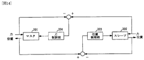
上記バイラテラル制御方式としては、上記特許文献1にも記載されるように図14に示すものや、図15に示すものが知られている。
図14に示すものは、マスタ201の位置とスレーブ202の位置との偏差を求め、この偏差に応じて位置制御部203によりスレーブ側の位置を制御するとともに、マスタ201とスレーブ202に作用する力を力検出器で検出し、その偏差をマスタ側にフィードバックして、力制御部204によりマスタ側の力を制御するようにしたものである。
また、図15に示すものは、マスタ201の位置とスレーブ202の位置との偏差を求め、この偏差に応じて位置制御部203によりスレーブ側の位置を制御するとともに、位置制御部203’によりマスタ側の位置を制御し、さらに、マスタ201とスレーブ202に作用する力を力検出器で検出し、その偏差をマスタ側にフィードバックして、力制御部204によりマスタ側の力を制御するとともに、力制御部204’によりスレーブ側を制御するようにしたものである。
さらに、上記のような力検出器と力制御部を備え、固い制御対象物でも安定して高精度な力制御を実現できるすると同時に、アームのどの部分に接触しても柔軟な特性を持つことができるロボットの制御装置が提案されている(特許文献2参照)
In FIG. 14, the deviation between the position of the
Further, in the example shown in FIG. 15, the deviation between the position of the
Furthermore, it is equipped with the force detector and force control unit as described above, and can realize stable and highly accurate force control even with a hard control target, and at the same time has flexible characteristics regardless of which part of the arm is touched. Has been proposed (see Patent Document 2).
上記従来の制御装置において、力または加速度情報の検出をする場合、歪みゲージなどの力センサあるいは加速度センサを用いて直接的に測定するのが一般的であった。
しかし、上記力センサや加速度センサを用いた直接的な力または加速度情報の検出では、以下のような問題点があった。
(i)信号ノイズの問題
力センサや加速度センサによる力の検出では微小なアナログ信号を増幅して検出しているが、信号に含まれるノイズも増幅してしまう。高周波ノイズに関しては低周波域通過フィルタを通すことによりその影響を除去することができるが、その場合には必要としている信号の周波数帯域までも狭めてしまう。
(ii)センサの固有周波数の問題
力センサを用いた力検出では、環境を直接力センサに接触させて測定する。力センサには物理的な固有周波数が存在し、それ以上高い周波数帯域での力測定は不可能である。
(iii)システムモデルの変化
力センサはシステムに直接設置するため、センサ慣性がそのままシステムモデルに加わってくる。また力センサでは加わった力に比例した歪みを利用して力を測定するが、このため力センサには物理的に剛性の低い材料が用いられている。しかし環境との接触を伴うシステムでは、この低剛性の力センサによりシステムモデルが変化してしまう。モデルの変化はシステムの制御においては致命的な問題である。
(iv)センサ価格の問題
一般的に力センサや加速度センサは高価であり、このため、装置全体も高価なものとなってしまう。In the conventional control device, when detecting force or acceleration information, it is common to directly measure using a force sensor such as a strain gauge or an acceleration sensor.
However, direct force or acceleration information detection using the force sensor or acceleration sensor has the following problems.
(I) Problem of signal noise In detection of force by a force sensor or an acceleration sensor, a minute analog signal is amplified and detected, but noise included in the signal is also amplified. The influence of high-frequency noise can be eliminated by passing through a low-frequency band pass filter, but in that case, the frequency band of the required signal is narrowed.
(Ii) Problem of sensor natural frequency In force detection using a force sensor, the environment is measured by directly contacting the force sensor. The force sensor has a physical natural frequency, and force measurement in a higher frequency band is impossible.
(Iii) Change of system model Since the force sensor is directly installed in the system, the sensor inertia is directly added to the system model. The force sensor uses a strain proportional to the applied force to measure the force. For this reason, a material having low physical rigidity is used for the force sensor. However, in a system involving contact with the environment, the system model is changed by the low-rigidity force sensor. Model change is a fatal problem in system control.
(Iv) Problem of sensor price Generally, the force sensor and the acceleration sensor are expensive, and thus the entire apparatus is also expensive.
また、位置および力等のように複数の変量を制御する場合、例えば前記図14、図15に示したように、位置検出器と力検出器を設け、位置制御系と力制御系により位置と力を制御するのが一般的である。
しかし、上記構成の制御系では、位置制御系と力制御系のそれぞれにより位置と力を制御しているので、位置制御系と力制御系が互いに干渉して、ゲインを上げることができず、誤差が残ってしまうことがある。
さらに、上記制御系において、歪みゲージなどの力センサを用いて力検出を行うと、前記したように力センサのノイズや固有周波数等の影響により、測定可能周波数帯域が狭い範囲に限定されてしまうとともに、力センサの慣性や低い剛性が、システムモデルに影響を与えてしまい、高い周波数帯域での応答性能を向上させることができない。
このため、従来のバイラテラル制御系においては、硬い環境に触ると不安定になったり、瞬間的な衝撃力が得られない、また、操作感が重いといった問題があり、繊細な感覚情報を伝えることができず、例えば遠隔医療等の分野などにおいて、繊細な作業を実現することは困難であった。
また、従来の制御系では、位置センサに加え、比較的高価な力センサを使用しており、装置価格が高くなるといった問題もあった。
本発明は上記従来技術の問題点を解決するためになされたものであって、本発明の目的は、高い周波数帯域での応答性能を向上させることができ、繊細な作業を実現することが可能な位置・力制御装置を提供することである。When a plurality of variables such as position and force are controlled, for example, as shown in FIGS. 14 and 15, a position detector and a force detector are provided, and the position control system and the force control system It is common to control the force.
However, since the position and force are controlled by the position control system and the force control system in the control system configured as described above, the position control system and the force control system interfere with each other, and the gain cannot be increased. An error may remain.
Furthermore, in the above control system, if force detection is performed using a force sensor such as a strain gauge, the measurable frequency band is limited to a narrow range due to the influence of noise and natural frequency of the force sensor as described above. At the same time, the inertia and low rigidity of the force sensor affect the system model, and the response performance in the high frequency band cannot be improved.
For this reason, in conventional bilateral control systems, there are problems such as instability when touching a hard environment, momentary impact force cannot be obtained, and the feeling of operation is heavy, and conveys delicate sensory information For example, in the field of telemedicine or the like, it has been difficult to realize delicate work.
Further, the conventional control system uses a relatively expensive force sensor in addition to the position sensor, and there is a problem that the price of the apparatus becomes high.
The present invention has been made to solve the above-described problems of the prior art, and the object of the present invention is to improve response performance in a high frequency band and to realize delicate work. Is to provide a simple position / force control device.
従来の歪みゲージを用いた力センサや、加速度センサのアナログ情報には信号ノイズが不可避であるが、位置情報はデジタル情報として検出可能なのでノイズの影響を受けにくい。
そこで、本発明においては、力センサに代えて反力検出手段を設け、位置情報より対象物に作用する反力を推定する。
これにより、ノイズを含まない反力を推定することができる。また、位置検出器はモータ軸とは非接触に位置情報を得ることができるので、力センサのような固有周波数による測定可能周波数帯域の制限がなく、非接触なのでセンサ設置による慣性および剛性などのシステムモデルの変化は起こらない。また、位置センサのみを用いているので、システムを安価に構築することができる。
また、従来のように位置制御系と力制御系をそれぞれ設けて位置および力を制御すると、位置制御系と力制御系が互いに干渉して、ゲインを上げることができない。
そこで、本発明においては、位置および力を加速度信号に変換し、両者を合成して、対象物を駆動する加速度指令信号である駆動信号を得るようにした。
これにより、位置制御と力制御が干渉することなく、それぞれのゲインを独立して設定することができる。
以上に基づき、本発明においては、次のようにして前記課題を解決する。
(1)対象物の位置を検出する位置検出手段を設け、位置情報と対象物を駆動する駆動手段への加速度指令信号である駆動信号に基づき、応力検出手段により対象物が受ける反力を推定する。
そして、上記対象物が受ける反力と目標となる力信号とから第1の加速度信号を求め、また、上記位置信号と目標位置とから第2の加速度信号を求め、上記第1、第2の加速度信号とを加算して、上記駆動手段への駆動信号となる加速度指令信号を出力する。
(2)上記(1)の制御を、位置指令信号、力指令信号に応じて対象物の位置、対象物が受ける力を制御する制御装置に適用する。
すなわち、対象物の位置を検出する位置検出手段を設け、上記のように、反力検出手段により対象物が受ける反力を推定する。
そして、位置指令信号と上記位置検出手段が出力する位置信号との偏差を求め、該偏差信号を第1の加速度信号に変換し、また、上記反力検出手段により検出された上記反力と、力指令信号との和を求め、該和を第2の加速度信号に変換し、第1、第2の加速度信号を加算して、上記駆動手段への駆動信号となる加速度指令信号を出力する。
(3)上記(1)の制御を、マスタ側の操作部とスレーブ側の対象物の位置偏差に応じて、スレーブ側の対象物とマスタ側の操作部の位置を制御し、マスタ側の操作力に応じた駆動力で対象物を駆動するとともに、対象物が受ける力をマスタ側に伝えるバイラテラル制御方式に適用する。
すなわち、マスタ側の操作部とスレーブ側の対象物の位置を検出する第1、第2の位置検出器をそれぞれ設け、また、上記のように第1、第2の反力検出手段によりマスタ側の操作部が受ける反力および、対象物が受ける反力を推定する。
そして、上記第1の位置検出手段が出力する位置信号と、第2の位置検出手段が出力する位置信号との偏差を求め、該偏差をマスタ側およびスレーブ側を制御するための第1、第2の加速度信号に変換する。また、上記第1の反力検出手段と、第2の反力検出手段の出力の和を求め、該和を、マスタ側およびスレーブ側を制御するための第3、第4の加速度信号に変換する。
上記第1,第3の加速度制御信号を加算するとともに、第2,第4の加速度制御信号を加算し、上記第1,第3の加速度制御信号の加算結果に基づき、上記マスタ側の操作部への駆動信号となる加速度指令信号を出力するとともに、上記第第2,第4の加速度制御信号の加算結果に基づき、上記スレーブ側の対象物への駆動信号となる加速度指令信号を出力する。
Signal noise is inevitable in analog information of a force sensor using a conventional strain gauge or an acceleration sensor, but position information can be detected as digital information and is not easily affected by noise.
Therefore, in the present invention, reaction force detection means is provided instead of the force sensor, and the reaction force acting on the object is estimated from the position information.
Thereby, the reaction force not including noise can be estimated. In addition, since the position detector can obtain position information in a non-contact manner with the motor shaft, there is no limit on the measurable frequency band due to the natural frequency like a force sensor, and since there is no contact, the inertia and rigidity due to sensor installation etc. The system model does not change. Moreover, since only the position sensor is used, the system can be constructed at low cost.
Further, if a position control system and a force control system are provided as in the conventional case to control the position and force, the position control system and the force control system interfere with each other, and the gain cannot be increased.
Therefore, in the present invention, the position and force are converted into an acceleration signal, and both are combined to obtain a drive signal that is an acceleration command signal for driving the object.
Thereby, each gain can be set independently, without position control and force control interfering.
Based on the above, in the present invention, the above-described problems are solved as follows.
(1) Position detection means for detecting the position of the object is provided, and a reaction force received by the object by the stress detection means is estimated based on the position information and a drive signal that is an acceleration command signal to the drive means for driving the object. To do.
Then, a first acceleration signal is obtained from the reaction force received by the object and a target force signal, and a second acceleration signal is obtained from the position signal and the target position, and the first and second acceleration signals are obtained. The acceleration signal is added to the acceleration signal , and an acceleration command signal serving as a driving signal for the driving means is output.
(2) The control of (1) is applied to a control device that controls the position of the object and the force received by the object in accordance with the position command signal and the force command signal.
That is, position detection means for detecting the position of the object is provided, and the reaction force received by the object is estimated by the reaction force detection means as described above.
Then, a deviation between the position command signal and the position signal output by the position detection means is obtained, the deviation signal is converted into a first acceleration signal, and the reaction force detected by the reaction force detection means, calculates the sum of the force command signal, converts the sum to a second acceleration signal, first, by adding the second acceleration signal, and outputs an acceleration command signal that is a driving signal to said driving means.
(3) The control in (1) is performed by controlling the position of the slave-side object and the master-side operation unit according to the positional deviation between the master-side operation unit and the slave-side object, and the master-side operation. The present invention is applied to a bilateral control system that drives an object with a driving force corresponding to the force and transmits the force received by the object to the master side.
That is, first and second position detectors for detecting the position of the master-side operation unit and the slave-side object are provided, respectively, and, as described above, the first-side and second-reaction-force detecting means are used for the master side. The reaction force received by the operation unit and the reaction force received by the object are estimated.
Then, a deviation between the position signal output from the first position detection means and the position signal output from the second position detection means is obtained, and the deviation is controlled by the first and second for controlling the master side and the slave side. 2 acceleration signal. Further, the sum of the outputs of the first reaction force detection means and the second reaction force detection means is obtained, and the sum is converted into third and fourth acceleration signals for controlling the master side and the slave side. To do.
The first and third acceleration control signals are added, and the second and fourth acceleration control signals are added. Based on the addition result of the first and third acceleration control signals, the master side operation unit it outputs an acceleration command signal that is a driving signal to, based on the addition result of the first second, fourth acceleration control signal, and outputs an acceleration command signal that is a driving signal to the slave side of the object.
本発明においては、以下の効果を得ることができる。
(1)反力検出手段を設け、位置検出手段の出力に基づき対象物に加わる力を推定しているので、信号ノイズやセンサ自体の固有周波数やセンサ慣性に影響されることなく、対象物の加わる力を求めることができる。
したがって、位置検出手段として高精度のセンサを用い、位置検出結果を短い周期でサンプリングすれば、対象物の位置、対象物に加わる力を応答性よく制御することができる。
また、センサとしては位置検出手段を設けるだけでよく、比較的高価な力センサを使用しないので、システムを安価に構築することができる。
(2)対象物が受ける反力と目標となる力信号とから第1の加速度信号を求め、また、上記位置検出手段により検出された位置信号と目標位置とから第2の加速度信号を求め、上記第1、第2の加速度信号を合成し、対象物を制御する駆動手段への駆動信号を出力するようにしたので、従来の制御装置のように位置、力制御が互いに干渉するといった問題が生ずることがなく、位置制御のゲインと力制御のゲインを独立に設定することが可能となる。このため、位置制御のゲインを大きくすることにより、位置誤差を生じさせることなく、リアルタイムで制御することができる。
(3)本発明をバイラテラル制御に適用し、マスタ側とスレーブ側に設けた位置検出手段の出力から位置偏差を求めて、加速度信号に変換し、また、マスタ側とスレーブ側に設けた反力検出手段により推定されたマスタ側とスレーブ側の反力を加算して加速度信号に変換し、上記位置偏差から求めた加速度信号と、反力の加算結果から求めた加速度信号を合成してマスタ側とスレーブ側を制御するようにしたので、上記のように位置制御のゲインと力制御のゲインを独立に設定することが可能となり、例えば、マスタ側とスレーブ側の位置誤差が零になるように、かつ、力については両者の和に倣うようにマスタ側とスレーブ側を制御することができる。
このため、マスタ側とスレーブ側の位置誤差を生じさせることなく、マスタ側の操作力をスレーブ側に応答性よく伝えることができるとともに、スレーブ側に加わる力をマスタ側に応答性よく伝えることができ、繊細な作業を実現することが可能となる。In the present invention, the following effects can be obtained.
(1) Since reaction force detection means is provided and the force applied to the object is estimated based on the output of the position detection means, the influence of the object is not affected by signal noise, the natural frequency of the sensor itself, or sensor inertia. The force applied can be calculated.
Therefore, if a highly accurate sensor is used as the position detection means and the position detection results are sampled in a short cycle, the position of the object and the force applied to the object can be controlled with good responsiveness.
Further, it is only necessary to provide a position detecting means as the sensor, and since a relatively expensive force sensor is not used, the system can be constructed at a low cost.
(2) A first acceleration signal is obtained from a reaction force received by the object and a target force signal, and a second acceleration signal is obtained from the position signal detected by the position detection means and the target position. Since the first acceleration signal and the second acceleration signal are combined and a driving signal is output to the driving means for controlling the object, there is a problem that the position and force control interfere with each other as in the conventional control device. This does not occur, and the gain for position control and the gain for force control can be set independently. Therefore, by increasing the position control gain, it is possible to control in real time without causing a position error.
(3) The present invention is applied to bilateral control, the position deviation is obtained from the output of the position detection means provided on the master side and the slave side, converted into an acceleration signal, and the reaction provided on the master side and the slave side The master side and slave side reaction forces estimated by the force detection means are added and converted into acceleration signals, and the acceleration signal obtained from the position deviation and the acceleration signal obtained from the reaction force addition result are synthesized to obtain the master signal. As described above, the position control gain and the force control gain can be set independently. For example, the position error on the master side and the slave side is zero. In addition, regarding the force, the master side and the slave side can be controlled to follow the sum of both.
For this reason, the operating force on the master side can be transmitted to the slave side with good responsiveness without causing a position error between the master side and the slave side, and the force applied to the slave side can be conveyed to the master side with high responsiveness. This makes it possible to achieve delicate work.
[図1]本発明の第1の実施例の位置・力制御装置の概略構成を示す図である。
[図2]外科医が手術等に使用される鉗子の構成例を示す図である。
[図3]本発明の第1の実施例におけるマスタ側の装置構成を示す図である。
[図4]本発明の第1の実施例におけるスレーブ側の装置構成を示す図である。
[図5]本発明の第1の実施例の制御系のブロック図である。
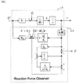
[図6]本発明で使用される反力オブザーバのブロック図である。
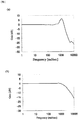
[図7]従来の力センサと反力推定オブザーバの周波数特性を示す図である。
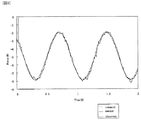
[図8]指令値を正弦波状に変化させた場合における従来の力センサと反力オブザーバの出力を示す図である。
[図9]反力オブザーバの他の構成例を示す図である。
[図10]本実施例の制御装置の応答特性(位置)を示す図である。
[図11]本実施例の制御装置の応答特性(力)を示す図である。
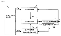
[図12]本発明の第2の実施例の位置・力制御装置の概略構成を示す図である。
[図13]本発明の第2の実施例の制御系のブロック図である。
[図14]従来のバイラテラル制御方式の構成例(1)を示す図である。
[図15]従来のバイラテラル制御方式の構成例(2)を示す図である。FIG. 1 is a diagram showing a schematic configuration of a position / force control apparatus according to a first embodiment of the present invention.
FIG. 2 is a diagram showing a configuration example of forceps used by a surgeon for surgery or the like.
FIG. 3 is a diagram showing a device configuration on the master side in the first embodiment of the present invention.
FIG. 4 is a diagram showing a device configuration on the slave side in the first embodiment of the present invention.
FIG. 5 is a block diagram of a control system according to the first embodiment of the present invention.
FIG. 6 is a block diagram of a reaction force observer used in the present invention.
FIG. 7 is a diagram showing frequency characteristics of a conventional force sensor and a reaction force estimation observer.
FIG. 8 is a diagram showing outputs of a conventional force sensor and reaction force observer when a command value is changed in a sine wave shape.
FIG. 9 is a diagram showing another configuration example of the reaction force observer.
FIG. 10 is a diagram showing response characteristics (position) of the control device according to the present embodiment.
FIG. 11 is a diagram showing response characteristics (force) of the control device of the present embodiment.
FIG. 12 is a diagram showing a schematic configuration of a position / force control apparatus according to a second embodiment of the present invention.
FIG. 13 is a block diagram of a control system according to a second embodiment of the present invention.
FIG. 14 is a diagram showing a configuration example (1) of a conventional bilateral control method.
FIG. 15 is a diagram showing a configuration example (2) of a conventional bilateral control method.
1 マスタ
1a リニアモータ
1b 位置検出器
1c 操作部
2,4 反力オブザーバ
3 スレーブ
3a リニアモータ
3b 位置検出器
3f 把持部
5 位置制御部
6 操作力制御部
7 加速度合成部
11 位置/力指令発生部
13 スレーブ
14 反力オブザーバ
15 位置制御部
16 操作力制御部
17 加速度合成部DESCRIPTION OF
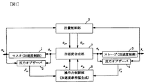
図1は本発明の第1の実施例の位置・力制御装置の概略構成を示す図であり、同図は本発明をバイラテラル制御に適用した場合の概略構成を示している。
同図において、1は作業者により操作されるマスタであり、例えば作業者により操作される操作部、該操作部を駆動するマスタ側モータ、該モータの位置を検出するマスタ側位置検出器から構成される。2は反力オブザーバであり、後述するように上記マスタ側位置検出器の出力と、上記マスタ側への駆動信号から上記操作部に加わる力を求める。
3はマスタ1の操作に応じて動作するスレーブであり、対象物を駆動するスレーブ側モータと、該モータの位置を検出するスレーブ側位置検出器から構成される。上記対象物とは、例えば、各種作業を行うロボットのハンドや、後述する鉗子であればその把持部等、遠隔地において実際に作業を行う操作部である(ここではこれらを含めて対象物と呼ぶこととする)。
4は反力オブザーバであり、上記マスタ側反力オブザーバと同様な構成を備え、後述するように上記スレーブ側位置検出器の出力と、上記スレーブ側への駆動信号から上記対象物に加わる力を求める。
上記マスタ側位置検出器により検出された操作部の位置、スレーブ側位置検出器により検出された対象物の位置信号xm,xsは、それぞれ位置制御部5に送られ、位置制御部5は上記位置信号を加速度参照値apm,apsに変換する。
また、マスタ側の反力オブザーバ2により検出されたマスタ側の力信号Fm、スレーブ側の反力オブザーバ2により検出されたスレーブ側の力信号Fsは操作力制御部6に送られ、操作力制御部6は、上記力信号Fm,Fsを加速度参照値afm,afsに変換する。
加速度合成部7は、上記加速度参照値apm,aps、加速度参照値afm,afsを合成し、マスタ側モータへの駆動信号となる加速度指令信号am、スレーブ側モータへの駆動信号となる加速度指令信号asを出力する。
本実施例の制御装置の反力オブザーバ2,4、位置制御部5、操作力制御部6、加速度合成部7は、コンピュータにより実現することができ、本実施例の制御装置をコンピュータで構成する場合には、上記位置検出器の出力を所定のサンプリング周期でコンピュータに取り込み、ソフトウェアにより上記機能を実現するための演算処理を行って、マスタ側、スレーブ側のモータを制御する。FIG. 1 is a diagram showing a schematic configuration of a position / force control apparatus according to a first embodiment of the present invention. FIG. 1 shows a schematic configuration when the present invention is applied to bilateral control.
In the figure,
4 is a reaction force observer, which has the same configuration as the master side reaction force observer. As will be described later, the force applied to the object from the output of the slave side position detector and the drive signal to the slave side is obtained. Ask.
The position of the operation unit detected by the master side position detector and the position signals x m and x s of the object detected by the slave side position detector are respectively sent to the
The master-side force signal F m detected by the master-side
The
The
次に、医療用の鉗子を遠隔制御する場合を例として、バイラテラル制御方式に適用した本発明の実施例の位置・力制御装置について説明する。
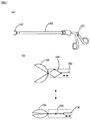
鉗子は、外科医が手術等に使用する医療器具であり、図2(a)に示すように、ハンドル部101(以下操作部101という)と鉗子部102(以下把持部102という)から構成される。
鉗子の軸部103内を操作部材(図示せず)が貫通しており、操作部101のハンドル1eを手で開閉することにより、上記操作部材が同図の左右方向に移動する。
把持部102は図2(b)に示すように、把持部102がリンク機構104に連結され、リンク機構104の他端側に上記操作部材105が連結されており、上記操作部101のハンドル1eを操作して、上記操作部材を同図の矢印方向に動かすことにより、把持部101を開閉させることができる。
本実施例では、上記鉗子を上記操作部101と把持部102の2つに分けて、操作部101をマスタ側、把持部102をスレーブ側とし、それぞれにリニアモータを連結し、該リニアモータを前記図1に示した制御系を用いて制御することにより、操作部101の操作に応じて、遠隔地に設置された把持部102を制御するようにした。
なお、以下では、操作部101の操作に応じて把持部を開閉させる1軸制御について説明するが、本実施例で説明する制御系を複数設けることにより操作部101の操作に応じて把持部全体を回転させたり、把持部全体を揺動させる等の多軸制御を行うこともできる。Next, the position / force control apparatus according to the embodiment of the present invention applied to the bilateral control system will be described by taking as an example the case of remotely controlling medical forceps.
The forceps is a medical instrument used by a surgeon for an operation or the like, and includes a handle portion 101 (hereinafter referred to as an operation portion 101) and a forceps portion 102 (hereinafter referred to as a grip portion 102), as shown in FIG. .
An operation member (not shown) passes through the
As shown in FIG. 2B, the
In this embodiment, the forceps are divided into two parts, the
In the following description, the single-axis control for opening and closing the gripper according to the operation of the
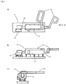
図3、図4は本実施例におけるマスタ側とスレーブ側の装置構成を示す図である。
図3(a)はマスタ側装置の上面図、(b)は側面図、(c)は同図(a)をA方向から見た図である。
同図において、1aはリニアモータであり、リニアモータ1aの可動軸1dに操作部1cを構成するハンドル1eの一方が連結され、ハンドル1eの他方はリニアモータ1aのケースに固定されている。従って、手で操作部1cのハンドル1eを操作することにより、リニアモータ1aの可動軸1dが同図(a)(b)の左右方向に動く。1bはマスタ側位置検出器でありリニアモータ1aの可動軸1dの位置を検出する。
図4(a)はスレーブ側装置の上面図、(b)は側面図、(c)は同図(a)をA方向から見た図である。
同図において、3aはリニアモータであり、リニアモータ3aの可動軸3dには、取付け金具3cを介して鉗子の軸部3d内を貫通する前記操作部材3eが連結され、操作部材3eの先端側には前記したようにリンク機構を介して把持部3fが取付けられている。
従って、リニアモータ3aの可動軸3dが同図(a)(b)の左右方向に動くことにより、操作部材3eが左右方向に動き把持部3fが開閉する。3bはスレーブ側位置検出器であり、リニアモータ3aの可動軸3dの位置を検出する。
なお、上記モータとしては、摩擦力の少ないモータを用いるのが望ましく、上記のようなリニアモータを使用する外、回転運動の場合にはダイレクトドライブモータ等を使用することができる。
また、上記位置検出器としては、高精度の検出器を用いるのが望ましく、また、応答性を向上させるには、位置検出器の検出結果を取り込むサンプリング周期を十分短くすることが必要である。FIG. 3 and FIG. 4 are diagrams showing device configurations on the master side and the slave side in this embodiment.
3A is a top view of the master side device, FIG. 3B is a side view, and FIG. 3C is a view of FIG.
In the figure, 1a is a linear motor, and one of the handles 1e constituting the
4A is a top view of the slave side device, FIG. 4B is a side view, and FIG. 4C is a view of FIG. 4A viewed from the A direction.
In this figure, 3a is a linear motor, and the operating shaft 3d penetrating the inside of the forceps shaft 3d is connected to the movable shaft 3d of the linear motor 3a via a mounting
Therefore, when the movable shaft 3d of the linear motor 3a moves in the left-right direction in FIGS. 4A and 4B, the
As the motor, it is desirable to use a motor having a small frictional force. In addition to using the linear motor as described above, a direct drive motor or the like can be used in the case of rotational movement.
Further, it is desirable to use a highly accurate detector as the position detector, and in order to improve the responsiveness, it is necessary to sufficiently shorten the sampling cycle for capturing the detection result of the position detector.
図5は本実施例の制御系のブロック図である。
同図において、前記図1の示したものと同一のものには同一の符号が付されており、1はマスタであり、マスタ1は図3に示したように、リニアモータ1aと位置検出器1bと操作部1cから構成される。マスタ側の反力オブザーバ2は、上記マスタ1のリニアモータ1aに供給される電流信号Iam refと、位置検出器1bにより検出されるリニアモータ1aの可動軸1dの位置(即ち操作部1cの位置)に応じた位置検出信号xmからマスタ側に加わる力の推定値Fmを求める。
3はスレーブであり、スレーブ3は図4に示したように、リニアモータ3aと位置検出器3bと前記機構により動作する把持部3fから構成される。
スレーブ側の反力オブザーバ4は、上記スレーブ2のリニアモータ3aに供給される電流信号Ias refと、位置検出器3bにより検出されるリニアモータ3aの可動軸3dの位置(即ち把持部1fの位置)に応じた位置検出信号xsからスレーブ側に加わる力の推定値Fsを求める。FIG. 5 is a block diagram of the control system of this embodiment.
In this figure, the same components as those shown in FIG. 1 are given the same reference numerals, 1 is a master, and
The
5は位置制御部であり、上記マスタ側の位置検出器1bにより検出されたマスタ側の操作部1cの位置信号xmと、スレーブ側の位置検出器3bにより検出されたスレーブ側の把持部1fの位置信号xsとの差を求める減算部5aと、減算部5aの出力に(Kvs+Kp)の演算を施す制御部5bと、制御部5bの出力に、〔Ms/(Mm+Ms)〕,〔−Ms/(Mm+Ms)〕を乗じて加速度参照値apm,apsを生成する変換部5c,5dから構成される。なお、ここで、Kpは位置ゲイン、Kvは速度ゲイン、Mmはマスタ側の慣性、Msはスレーブ側の慣性である。
6は操作力制御部であり、マスタ側の反力オブザーバ2が出力するマスタ側の操作部1cに加わる力の推定値Fmとスレーブ側の反力オブザーバ4が出力するスレーブ側の把持部3fに加わる力の推定値Fsとの和を出力する加算部6aと、加算部6aの出力に力ゲインKfを乗算し、加速度参照値afm,afsを生成する変換部6bとから構成される。上記力ゲインKfは仮想慣性の逆数であり任意の値に設定することができ、Kfを適切に設定することにより、等価質量を見かけ上小さくすることができる。
7は加速度合成部であり、上記加速度参照値apm,afmを加算してマスタ側の加速度参照値(xm ref)″を出力する加算部7aと、加算部7aの出力に〔Mm/Ktnm〕を乗じて、マスタ側のリニアモータ1aを駆動する電流参照値Iam refを生成する変換部7bと、上記加速度参照値aps,afsを加算してスレーブ側の加速度参照値(xs ref)″を出力する加算部7cと、加算部7cの出力に〔Ms/Ktns〕を乗じて、スレーブ側のリニアモータ3aを駆動する電流参照値Ias refを生成する変換部7dとから構成される。ここで、Mm,Msは前記したマスタ側の慣性、スレーブ側の慣性であり、Ktnm,Ktnsはそれぞれマスタトルク定数、スレーブトルク定数である。
なお、図面上では、一次微分、2次微分を符号の上にドットを1または2付けて示すが、明細書中では一次微分を「’」を付して示し、2次微分を上記(xm ref)″のように「”」を付けて示す。
6 is an operation force control unit, the slave side of the grip portion 3f to estimate F m and reaction force observer fourth slave force applied to the master side of the
In the drawing, the primary differentiation and the secondary differentiation are indicated by adding 1 or 2 to the symbol, but in the specification, the primary differentiation is indicated by “′”, and the secondary differentiation is indicated by the above (x m ref ) "
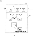
図6は、反力オブザーバ2,4のブロック図である。
同図において、1,3はマスタ側、スレーブ側のブロック図であり、Ia refはリニアモータ1a,3aに供給される電流参照値、Ktは推力定数であり、Ia ref×Ktはリニアモータの駆動力に相当する。Flはリニアモータの負荷、Mはマスタ側、スレーブ側の慣性であり、リニアモータ1a,3aに電流Ia refが供給され、負荷がFlのとき、マスタ側、スレーブ側は、同図に示す速度x’で動き、その位置xは速度x’を積分した値となる。
反力オブザーバ2,4には上記電流参照値Ia ref、位置xが入力され、反力オブザーバ2,4は以下の(1)式によりマスタ側、スレーブ側の推定反力Fm,Fs(=F)を求める。
F=〔g/(s+g)〕×〔Ia refKtn+xMnsg−Finit〕−Mnsg…(1)ここで、Finit=Fdis+Dx’+(M−Mn)x’である。また、g/(s+g)は一次の周波数選択フィルタである。
上記式および図6中の各記号は以下の値を表している。
M:慣性、Mn:慣性公称値、Ktn:推力定数公称値、x:位置、x’:速度、Fdis:クーロン摩擦、D:粘性摩擦係数。
なお、Fdis,D,M,Mn等は予備実験により求めた既知の値であるとする。
上記反力オブザーバを用いて反力を推定することにより、力センサを用いる場合に比べ、前記したように、信号ノイズやセンサ自体の固有周波数やセンサ慣性に影響されることなく、かつ安価にマスタ側、スレーブ側の反力を推定することができる。またクーロン摩擦、粘性摩擦係数による影響を最小限にすることもできる。FIG. 6 is a block diagram of the
In the figure,
The
F = [g / (s + g)] × [I a ref K tn + xM n sg-F init ] -M n sg ... (1) where, F init = F dis + Dx '+ (M-M n) x' It is. G / (s + g) is a primary frequency selection filter.
The above formula and each symbol in FIG. 6 represent the following values.
M: inertia, Mn : nominal inertia value, Ktn : thrust constant nominal value, x: position, x ': velocity, Fdis : Coulomb friction, D: viscous friction coefficient.
Note that F dis , D, M, M n and the like are known values obtained by preliminary experiments.
By estimating the reaction force using the reaction force observer, as described above, it is not affected by signal noise, the natural frequency of the sensor itself, or the sensor inertia, and at a lower cost than when using a force sensor. Side and slave side reaction force can be estimated. In addition, the influence of Coulomb friction and viscous friction coefficient can be minimized.
間接的センシングの有効性を確認するため、従来の歪みゲージを用いた力センサを用いて直接力を測定した場合と、反力推定オブザーバを用いて間接的に力を測定した場合を比較した。
図7に実験結果を示す。同図の横軸はω(rad/sec)、縦軸はgain(dB)であり、同図(a)は従来の力センサの周波数特性、(b)は反力オブザーバの周波数特性を示す。
同図から明らかなように、従来の力センサでは固有周波数の存在により、測定可能周波数帯域が約500rad/sec以下に限定されてしまうが、反力推定オブザーバでは設定したゲイン1500rad/secまでの広帯域で測定できる。
図8は指令値(印加する力)を正弦波状に変化させて、従来の歪みゲージを用いた力センサと上記反力オブザーバの出力を比較した図である。同図の横軸は時間(秒)、縦軸は力(ニュートン)であり、同図の点線は指令値(与えた力)、破線は上記反力オブザーバによる推定結果、実線は従来の力センサによる検出結果を示す(指令値と反力オブザーバによる推定結果はほぼ重なっている)。
同図の示すように、反力オブザーバの出力は、指令値とほぼ一致しているが、従来の力センサの出力は、上記指令値よりやや遅れており、また、固有周波数や慣性の影響により検出結果が一部振動的に変化している。In order to confirm the effectiveness of indirect sensing, we compared the case where the force was measured directly using a force sensor using a conventional strain gauge and the case where the force was measured indirectly using a reaction force observer.
FIG. 7 shows the experimental results. In the figure, the horizontal axis is ω (rad / sec), the vertical axis is gain (dB), FIG. 10A shows the frequency characteristics of a conventional force sensor, and FIG. 9B shows the frequency characteristics of a reaction force observer.
As is clear from the figure, in the conventional force sensor, the measurable frequency band is limited to about 500 rad / sec or less due to the presence of the natural frequency, but the reaction force estimation observer has a wide band up to the set gain of 1500 rad / sec. Can be measured.
FIG. 8 is a diagram comparing the output of the reaction force observer with a force sensor using a conventional strain gauge by changing the command value (force to be applied) in a sine wave shape. The horizontal axis in the figure is time (seconds), the vertical axis is force (Newton), the dotted line in the figure is the command value (given force), the broken line is the estimation result by the reaction force observer, and the solid line is the conventional force sensor (The command value and the estimation result by the reaction force observer almost overlap).
As shown in the figure, the output of the reaction force observer is almost the same as the command value, but the output of the conventional force sensor is slightly behind the command value, and is also affected by the natural frequency and inertia. The detection result is partially vibrating.
図7、図8から明らかなように、反力オブザーバを用いれば、従来の力センサを用いた場合に比べ、広帯域での測定が可能であり、また、殆ど遅れなくマスタ側、スレーブ側に加わる力を推定することができ、これによりマスタ側、スレーブ側を応答よく制御することができる。
上記反力オブザーバは、例えば、「大西,”外乱オブザーバによるロバスト・モーションコントロール”日本ロボット学会誌vol.11,no.4,pp.486〜493,1993」等に開示されている。
図9は、反力オブザーバの他の構成例を示す図であり、同図は、周波数選択フィルタとして、図6に示した〔g/(s+g)〕に替え、〔k1/(s2+k2s+k1)〕の伝達関数で表される2次フィルタを用いた場合を示している。
上記〔k1/(s2+k2s+k1)〕の極は、s2+k2s+k1=0から得られ、この極をα,βとすると、α+β=−k2、αβ=k1となる。
なお、上記図9に示した反力オブザーバについては、例えば「k.Ohnishi,M.Shibata,T.Murakami,″Motion Control for Advanced Mechatoronics″,IEEE/ASME Transactions on Mechatronics」等を参照されたい。As is clear from FIG. 7 and FIG. 8, using the reaction force observer enables measurement in a wide band compared to the case of using a conventional force sensor, and adds to the master side and slave side with almost no delay. The force can be estimated, whereby the master side and the slave side can be controlled with good response.
The reaction force observer is disclosed in, for example, “Onishi,“ Robust Motion Control by Disturbance Observer ”, Journal of the Robotics Society of Japan vol.11, no.4, pp.486-493, 1993”.
FIG. 9 is a diagram illustrating another configuration example of the reaction force observer, in which FIG. 9 replaces [g / (s + g)] illustrated in FIG. 6 as a frequency selection filter with [k 1 / (s 2 + k). 2 s + k 1 )]] is used.
The pole of [k 1 / (s 2 + k 2 s + k 1 )] is obtained from s 2 + k 2 s + k 1 = 0, and when these poles are α and β, α + β = −k 2 , αβ = k 1 Become.
For the reaction force observer shown in FIG. 9, for example, “k.
次に、図3、図4、図5に示す本実施例の制御装置の動作について説明する。
マスタ側の操作部1cを操作すると、リニアモータ1aの可動軸1dが移動し、位置検出器1aにより可動軸1dの位置が検出される。
この位置検出器1aの出力と、スレーブ側の位置検出器3aの出力が位置制御部5に送られ、位置制御部5はその偏差に基づき加速度参照値apm,apsを生成し出力する。
一方、マスタ側の反力オブザーバ2はマスタ側に加わる力の推定値Fmを出力する。
操作力制御部6は、上記マスタ側に加わる力の推定値Fmと、スレーブ側の反力オブザーバ4が出力するスレーブ側に加わる力Fsの和を求め、この和から加速度参照値afm,afsを生成し出力する。
上記加速度参照値apsと加速度参照値afsは、加速度合成部7に送られ、加速度合成部7は上記加速度参照値apsと加速度参照値afsの和から、電流参照値Ias refを生成する。また、上記加速度参照値apmと加速度参照値afmの和から、電流参照値Iam refを生成する。
上記電流生成値Ias refはスレーブ側のリニアモータ3aに与えられ、リニアモータ3aが駆動される。同様に、上記電流生成値Iam refはマスタ側のリニアモータ1aに与えられ、リニアモータ1aが駆動される。Next, the operation of the control device of the present embodiment shown in FIGS. 3, 4, and 5 will be described.
When the
The output of the
On the other hand, the reaction-
The operating
The acceleration reference value a ps and the acceleration reference value a fs are sent to the
The current generation value I as ref is given to the linear motor 3a on the slave side, and the linear motor 3a is driven. Similarly, the current generation value I am ref is given to the
マスタ側の操作部1cを操作することにより、スレーブ側のリニアモータ3aの可動軸とマスタ側のリニアモータ1aの可動軸に位置誤差が生ずると、上記加速度合成部7から、マスタ側のリニアモータ1aとスレーブ側のリニアモータ3aに上記位置誤差を修正するような駆動信号が与えられ、マスタ側のリニアモータ1a、スレーブ側のリニアモータ3aの可動軸が駆動される。
これにより、マスタ側のリニアモータ1aとスレーブ側のリニアモータ3aの可動軸の位置が一致するように制御される。すなわち、マスタ側の操作部1cのハンドル1eの位置に応じて、スレーブ側の把持部3fの開度が制御される。
また、これと同時に、把持部3fに加わる力Fsが反力オブザーバ4で推定されるとともに、操作部1cに加わる力Fmが反力オブザーバ2で推定され、FsとFmとの和に応じた加速度参照値afm、afsが加速度合成部7に与えられる。
加速度合成部7は、把持部3fに加わる力Fsと操作部1cに加わる力Fmの和に応じて、マスタ側のリニアモータ1aとスレーブ側のリニアモータ3aを駆動する。
これにより、マスタ側の操作部1cに加わる力とスレーブ側の把持部3fに加わる力との和に倣うように、マスタ側の操作部1cとスレーブ側の把持部3fが制御される。
すなわち、マスタ側の操作部1cを操作して、スレーブ側の把持部3fで物体を把持すると、把持部3fに加わる反力に応じた力が操作部1cに伝わり、これにより、作業者は把持部3fで把持した物体からの反力等を操作部1cで感じ取ることができる。
以上の説明では、マスタ側を操作した場合について説明したが、スレーブ側を操作した場合でも上記と同様にマスタ側が制御され、スレーブ側にマスタ側の力が伝えられる。When a position error occurs between the movable shaft of the slave-side linear motor 3a and the movable shaft of the master-side
As a result, control is performed so that the positions of the movable axes of the master-side
The sum of the same time, with the force F s applied to the grip portion 3f is estimated by the
Thereby, the master
That is, when the master-
In the above description, the case where the master side is operated is described. However, even when the slave side is operated, the master side is controlled in the same manner as described above, and the master side force is transmitted to the slave side.
本実施例のバイラテラル制御装置は、上記のように、マスタ側の操作部、スレーブ側の対象物の位置を検出する位置検出手段を設け、位置検出手段の出力に基づき、反力オブザーバにより、マスタ側の操作部、スレーブ側の対象物が受ける反力を推定しているので、信号ノイズやセンサ自体の固有周波数やセンサ慣性に影響されることなく、かつ安価にスレーブ側の対象物に加わる反力を推定することができる。またクーロン摩擦、粘性摩擦係数による影響を最小限にすることもできる。
このため、位置検出手段として高精度のセンサを用い、位置検出結果を比較的短い周期でサンプリングし、位置制御部の制御ゲインを大きく設定すれば、マスタ側とスレーブ側の位置誤差を生じさせることなく、位置および操作力を応答性よく制御することができる。
また、位置制御部5と操作力制御部6を設けて、加速度合成部で位置制御部5と操作力制御部6で生成した加速度参照値を合成して、リニアモータを駆動しているので、位置制御のゲインと操作力制御のゲインを独立に設定することが可能となる。
このため、マスタ側とスレーブ側の位置誤差が無くなるように位置制御部5を設定することができ、また、マスタ側とスレーブ側の反力の和に倣うように両者を制御することができる。さらに、操作力制御部6の力ゲインKfの設定により、マスタ側の操作力を自由に設定することができる。As described above, the bilateral control device of the present embodiment is provided with position detecting means for detecting the position of the master side operation unit and the slave side object, and based on the output of the position detecting means, the reaction force observer Since the reaction force received by the operation unit on the master side and the object on the slave side is estimated, it is not affected by the signal noise, the natural frequency of the sensor itself, or the sensor inertia, and is added to the object on the slave side at a low cost. The reaction force can be estimated. In addition, the influence of Coulomb friction and viscous friction coefficient can be minimized.
For this reason, if a high-precision sensor is used as the position detection means, the position detection results are sampled in a relatively short cycle, and the control gain of the position control unit is set large, a position error between the master side and the slave side may occur. In addition, the position and operating force can be controlled with good responsiveness.
In addition, since the
For this reason, the
本実施例のバイラテラル制御装置により前記鉗子を遠隔制御して、本発明の有効性を確認した。
実験では、制御装置をコンピュータで構成し、位置検出器として、分解能が1μm程度のリニアエンコーダを用い、100μs程度のサンプリング周期でコンピュータで構成された制御装置に取り込んで、鉗子をバイラテラル制御した。これにより、160Hz程度の応答性を得ることができた。
図10、図11に上記実験結果を示す。
なお、図10、図11の横軸は時間(sec)、図10の縦軸は位置、図11の縦軸は力(ニュートン)であり、位置、力をステップ状に変化させたときの応答特性を示す。
前記した従来のバイラテラル制御系では環境接触時において位置偏差が生じてしまい位置再現性が悪かったが、本発明においては、計算機のサンプリング時間を十分に短して周波数帯域を十分広く確保し、位置制御部5の制御ゲインを上げることにより、図10に示すように位置偏差を生じることなくリアルタイムに環境を再現できた。The effectiveness of the present invention was confirmed by remotely controlling the forceps with the bilateral control device of this example.
In the experiment, the control device was configured by a computer, a linear encoder having a resolution of about 1 μm was used as a position detector, and the forceps was bilaterally controlled by taking it into the control device configured by the computer at a sampling period of about 100 μs. Thereby, the response of about 160 Hz could be obtained.
10 and 11 show the experimental results.
10 and 11, the horizontal axis is time (sec), the vertical axis in FIG. 10 is the position, and the vertical axis in FIG. 11 is the force (Newton). The response when the position and force are changed stepwise. Show properties.
In the conventional bilateral control system described above, a positional deviation occurred at the time of environmental contact and the position reproducibility was poor, but in the present invention, the sampling time of the computer is sufficiently shortened to ensure a sufficiently wide frequency band, By increasing the control gain of the
以上説明した実施例では、本発明をバイラテラル制御に適用する場合について説明したが、本発明は、上記バイラテラル制御に限らず、位置指令値、力指令値に応じてスレーブ側を制御する制御装置に適用することもできる。
図12に上記のように位置指令値、力指令値に応じてスレーブ側を制御する本発明の第2の実施例の位置・力制御装置の概略構成を示す。
同図において、11は位置指令値と力指令値を発生する位置/力指令発生部であり、位置/力指令発生部11が出力する位置指令値xrefは位置制御部15に与えられ、力指令値frefは、操作力制御部16に与えられる。
13は上記位置指令、力指令に応じて動作するスレーブであり、前記したように、対象物を駆動するスレーブ側モータと、該モータの位置を検出するスレーブ側位置検出器から構成される。上記対象物とは、例えば、各種作業を行うロボットのハンド等、遠隔地において実際に作業を行う操作部である。
14は反力オブザーバであり、前記したように、スレーブ側位置検出器の出力と、上記スレーブ側への駆動信号から上記対象物に加わる力を求める。
上記位置指令値xrefとスレーブ側に設けられた位置検出器により検出された対象物の位置信号xsは、それぞれ位置制御部15に送られ、位置制御部15は上記位置信号を加速度参照値apsに変換する。
また、力指令値frefとスレーブ側の反力オブザーバ12により検出されたスレーブ側の力信号fsは操作力制御部16に送られ、操作力制御部16は、上記力信号fref,fsを加速度参照値afsに変換する。
加速度合成部17は、上記加速度参照値aps、加速度参照値afsを合成し、スレーブ側モータへの駆動信号となる加速度指令信号asを出力する。In the embodiment described above, the case where the present invention is applied to bilateral control has been described. However, the present invention is not limited to the above-described bilateral control, and control for controlling the slave side according to the position command value and the force command value. It can also be applied to a device.
FIG. 12 shows a schematic configuration of the position / force control apparatus according to the second embodiment of the present invention for controlling the slave side in accordance with the position command value and the force command value as described above.
In the figure,
14 is a reaction force observer, and as described above, the force applied to the object is obtained from the output of the slave side position detector and the drive signal to the slave side.
The position command value x ref and the position signal x s of the object detected by the position detector provided on the slave side are respectively sent to the
Further, the force command value f ref and the slave-side force signal f s detected by the slave-side
上記位置/力指令発生部11が発生する位置指令値、力指令値は、予めプログラミングされた値であり、例えば、熟練した作業者等による操作等を記憶することにより得ることができる。
例えば、前記実施例に示したバイラテラル制御装置を用いて熟練した作業者により所望の作業をしてもらい、マスタ側(もしくはスレーブ側)の位置xm(またはxs)、応力オブザーバの出力fm(またはfs)を、それぞれ位置指令値、力指令値として記憶しておく。そして、この記憶された位置指令値、力指令値を上記位置/力指令発生部11から出力し、スレーブ側を制御することにより、熟練した作業者による作業を再現することができる。The position command value and the force command value generated by the position / force
For example, a skilled worker performs a desired work using the bilateral control device shown in the above embodiment, and the master side (or slave side) position x m (or x s ) and the stress observer output f m (or f s ) is stored as a position command value and a force command value, respectively. The stored position command value and force command value are output from the position / force
図13は、本実施例の制御系のブロック図である。
同図において、11は上記位置/力指令発生部、13はスレーブであり、スレーブ13は前記したように、リニアモータ等のモータと、位置検出器を備える。
14は反力オブザーバであり、前記図6、図9に示した構成を備え、スレーブ13のモータに供給される電流信号Ias ref と、位置検出器により検出される位置に応じた位置検出信号xs からスレーブ側に加わる力の推定値Fs を求める。
15は位置制御部であり、上記位置/力指令発生部11が出力する位置指令値xref と、とスレーブ側の位置検出器により検出されたスレーブ側の位置信号xs との差を求める減算部15aと、減算部15aの出力に(Kv s+Kp )の演算を施す制御部15bと、加速度参照値apsを生成する変換部15cから構成される。なお、ここで、Kp は位置ゲイン、Kv は速度ゲインである。
16は操作力制御部であり、力指令値fref と反力オブザーバ14が出力するスレーブ側の対象物に加わる力の推定値Fs との和を出力する加算部16aと、加算部16aの出力に力ゲインKf を乗算し、加速度参照値afsを生成する変換部16bとから構成される。上記力ゲインKf は前記したように仮想慣性の逆数であり任意の値に設定することができ、Kf を適切に設定することにより等価質量を見かけ上小さくすることができる。
7は加速度合成部であり、上記加速度参照値aps,afs を加算してスレーブ側の加速度参照値(xs ref )" を出力する加算部17aと、加算部17aの出力に〔Ms /Ktns 〕を乗じて、スレーブ側のモータを駆動する電流参照値Ias ref を生成する変換部17bとから構成される。ここで、Ms はスレーブ側の慣性であり、Ktns はスレーブトルク定数である。
FIG. 13 is a block diagram of the control system of this embodiment.
In the figure, 11 is the position / force command generating unit, 13 is a slave, and the
A
次に、図13に示す本実施例の制御装置の動作について説明する。
位置/力指令発生部11が出力する位置指令値xref とスレーブ側の位置検出器3aの出力が位置制御部15に送られ、位置制御部15はその偏差に基づき加速度参照値apsを生成し出力する。
一方、操作力制御部16は、上記位置/力指令発生部11が出力する力指令値fref と反力オブザーバ4が出力するスレーブ側に加わる力Fs の和を求め、この和から加速度参照値afsを生成し出力する。
上記加速度参照値apsと加速度参照値afSは、加速度合成部17に送られ、加速度合成部17は上記加速度参照値apsと加速度参照値afsの和から、電流参照値Ias ref を生成する。上記電流生成値Ias ref はスレーブ側のモータに与えられ、モータが駆動される。
位置指令値xref が変化すると、スレーブ側のモータの位置との位置誤差が生じ、加速度合成部17から、スレーブ側のモータに上記位置誤差を修正するような駆動信号が与えられ、スレーブ側のモータが駆動される。
これにより、上記位置指令値にスレーブ側の位置が一致するように制御される。
また、これと同時に、スレーブ側に加わる力Fs が反力オブザーバ4で推定され、力指令値fref とFs との偏差に応じた加速度参照値afsが加速度合成部17に与えられる。
加速度合成部17は、力指令値fref とスレーブ側の力Fs の大きさが異なると、この大きさが一致するような駆動信号をスレーブ側のモータに与える。これにより、スレーブ側に加わる力が力指令値fref に一致するように制御される。
Next, the operation of the control device of this embodiment shown in FIG. 13 will be described.
The position command value xref output from the position /
On the other hand, the operating
The acceleration reference value a ps and the acceleration reference value a fS are sent to the
When the position command value x ref changes, a position error with respect to the position of the motor on the slave side occurs, and a driving signal for correcting the position error is given from the
Thus, control is performed so that the position on the slave side matches the position command value.
At the same time, the force F s applied to the slave side is estimated by the
If the magnitudes of the force command value f ref and the slave side force F s are different, the
本実施例においては、上記のように、スレーブ側の対象物の位置を検出する位置検出手段を設け、位置検出手段の出力に基づき、反力オブザーバにより、対象物が受ける反力を推定しているので、第1の実施例と同様、信号ノイズやセンサ自体の固有周波数やセンサ慣性に影響されることなく、かつ安価にスレーブ側の対象物に加わる反力を推定することができる。またクーロン摩擦、粘性摩擦係数による影響を最小限にすることもできる。
このため、位置検出手段として高精度のセンサを用い、位置検出結果を比較的短い周期でサンプリングし、位置制御部の制御ゲインを大きく設定すれば、位置誤差を生じさせることなく、スレーブ側の位置、操作力を応答性よく制御するこができる。
また、位置制御部15と操作力制御部16を設けて、加速度合成部17で位置制御部15と操作力制御部16で生成した加速度参照値を合成して、スレーブ側の対象物を駆動しているので、第1の実施例と同様、位置制御のゲインと操作力制御のゲインを独立に設定することが可能となる。In the present embodiment, as described above, the position detection means for detecting the position of the object on the slave side is provided, and based on the output of the position detection means, the reaction force received by the object is estimated by the reaction force observer. Thus, as in the first embodiment, the reaction force applied to the slave object can be estimated at low cost without being affected by signal noise, the natural frequency of the sensor itself, or the sensor inertia. In addition, the influence of Coulomb friction and viscous friction coefficient can be minimized.
For this reason, if a high-precision sensor is used as the position detection means, the position detection result is sampled at a relatively short period, and the control gain of the position control unit is set large, the position on the slave side is not generated without causing a position error. The operation force can be controlled with good responsiveness.
Further, the
本発明は、医療分野、建築用作業ロボット、食品加工や食品のハンドリング、アッセッブル、楽器の操作等の各種分野に適用することができ、バイラテラル制御系に適用すれば、マスタ側の操作力をスレーブ側に応答性よく伝えることができるとともに、スレーブ側に加わる力をマスタ側に応答性よく伝えることができ、繊細な作業を実現することが可能となる。
例えば、本発明を医療分野で使用される鉗子等の遠隔制御に適用すれば、従来の遠隔手術では実現することができなかった繊細な感覚情報を伝えることができ、鉗子を直接手で操作する場合と同様な感覚で使用することが可能となる、また、繊細な感覚情報を伝えることが必要な触診等を遠隔から行うことも可能となる。
また、建築用作業ロボットに適用することにより、セメント塗り等の作業を熟練した作業者が直接手で塗ったのと同様に行うことができ、さらに、食品のハンドリング作業やアッセンブル、楽器の操作等においても、人手による作業や操作と同様に行うことが可能となる。The present invention can be applied to various fields such as medical field, construction work robot, food processing and food handling, assembly, instrument operation, etc. When applied to a bilateral control system, the operation force on the master side can be reduced. While being able to transmit to the slave side with sufficient responsiveness, the force applied to the slave side can be transmitted to the master side with high responsiveness, and delicate work can be realized.
For example, if the present invention is applied to remote control of forceps used in the medical field, delicate sensory information that cannot be realized by conventional remote surgery can be transmitted, and the forceps are directly operated by hand. It becomes possible to use it with the same feeling as in the case, and it is also possible to remotely perform palpation and the like that need to convey delicate sensory information.
In addition, by applying it to construction work robots, it is possible to carry out operations such as cement coating in the same way that skilled workers have applied directly by hand, and further, food handling operations and assembly, operation of musical instruments, etc. In this case, it is possible to carry out in the same manner as manual operations and operations.
Claims (3)
上記対象物を駆動する駆動手段と、
上記位置検出手段が出力する位置信号と、上記駆動手段への加速度指令信号である駆動信号に基づき上記対象物が受ける反力を求める反力検出手段と、
上記対象物が受ける反力と目標となる力信号とから第1の加速度信号を求めるとともに、上記位置信号と目標位置とから第2の加速度信号を求め、上記第1、第2の加速度信号とを加算して、上記駆動手段への駆動信号となる加速度指令信号を出力する制御手段を備えた
ことを特徴とする位置・力制御装置。Position detecting means for detecting the position of the object;
Driving means for driving the object;
A position signal output by the said position detection means, a reaction force detecting means for obtaining a reaction force which the object is subjected on the basis of the drive signal is an acceleration command signal to the drive means,
Together determining a first acceleration signal from the force signal as a reaction force and a target which the object is subjected, it obtains a second acceleration signal from the said position signal and a target position, the first and second acceleration signal and A position / force control apparatus comprising control means for adding an acceleration signal and outputting an acceleration command signal as a drive signal to the drive means.
上記対象物を駆動する駆動手段と、
上記対象物の位置を検出する位置検出手段と、
上記位置検出手段が出力する位置信号と、上記駆動手段への加速度指令信号である駆動信号から、該対象物が受ける反力を求める反力検出手段と、
位置指令信号と上記位置検出手段が出力する位置信号との偏差を求め、該偏差信号を第1の加速度信号に変換する第1の演算手段と、
上記反力検出手段により検出された上記反力と、力指令信号との和を求め、該和を第2の加速度信号に変換する第2の演算手段と、
上記第1、第2の加速度信号とを加算して、上記駆動手段への駆動信号となる加速度指令信号を出力する制御手段を備えた
ことを特徴とする位置・力制御装置。A position / force control device for controlling a position of a target and a force acting on the target according to a position command signal and a force command signal,
Driving means for driving the object;
Position detecting means for detecting the position of the object;
A position signal output by the said position detection means, the drive signal is an acceleration command signal to the drive means, and the reaction force detecting means for obtaining a reaction force which the object is subjected,
A first computing means for obtaining a deviation between the position command signal and the position signal output from the position detecting means, and converting the deviation signal into a first acceleration signal;
And the reaction force detected by the reaction force detecting means obtains the sum of the force command signal, a second arithmetic means for converting the sum to the second acceleration signal,
A position / force control device comprising control means for adding the first and second acceleration signals and outputting an acceleration command signal as a drive signal to the drive means.
マスタ側の操作部を駆動する第1の駆動手段と、
マスタ側の操作部の位置を検出する第1の位置検出手段と、
上記第1の位置検出手段が出力する位置信号と、上記第1の駆動手段への加速度指令信号である駆動信号から、上記操作部に作用する反力を求める第1の反力検出手段と、
スレーブ側の対象物を駆動する第2の駆動手段と、
スレーブ側の対象物の位置を検出する第2の位置検出手段と、
上記第2の位置検出手段が出力する位置信号と、上記第2の駆動手段への加速度指令信号である駆動信号から、上記対象物が受ける反力を求める第2の反力検出手段と、
上記第1の位置検出手段が出力する位置信号と、第2の位置検出手段が出力する位置信号との偏差を求め、該偏差をマスタ側およびスレーブ側を制御するための第1、第2の加速度信号に変換する第1の演算手段と、
上記第1の反力検出手段と、上記第2の反力検出手段の出力の和を求め、該和をマスタ側およびスレーブ側を制御するための第3、第4の加速度信号に変換する第2の演算手段と、
上記第1,第3の加速度信号を加算する第1の加算手段と、
上記第2,第4の加速度信号を加算する第2の加算手段と、
上記第1の加算手段の出力に基づき、上記マスタ側の操作部への駆動信号となる加速度指令信号を出力する第1の制御手段と、
上記第2の加算手段の出力に基づき、上記スレーブ側の対象物への駆動信号となる加速度指令信号を出力する第2の制御手段とを備えた
ことを特徴とする位置・力制御装置。Controls the position of the slave-side object and the master-side operation unit according to the positional deviation between the master-side operation unit and the slave-side object, and drives the object with a driving force according to the master-side operation force. And a position / force control device that transmits the force received by the object to the master side,
First driving means for driving the master side operation section;
First position detecting means for detecting the position of the operation unit on the master side;
A position signal to said first position detecting means outputs, from the drive signal is an acceleration command signal to said first drive means, and the first reaction force detecting means for obtaining a reaction force acting on the operating unit ,
A second driving means for driving the object on the slave side;
Second position detecting means for detecting the position of the slave object;
A position signal to said second position detecting means outputs, from the drive signal is an acceleration command signal to the second drive means, and the second reaction force detecting means for obtaining a reaction force which the object is subjected,
A deviation between the position signal output from the first position detection means and the position signal output from the second position detection means is obtained, and the deviation is controlled by the first and second for controlling the master side and the slave side. First computing means for converting to an acceleration signal;
A sum of outputs of the first reaction force detection means and the second reaction force detection means is obtained, and the sum is converted into third and fourth acceleration signals for controlling the master side and the slave side. Two computing means;
First addition means for adding the first and third acceleration signals;
Second addition means for adding the second and fourth acceleration signals;
First control means for outputting an acceleration command signal as a drive signal to the master side operation section based on the output of the first addition means;
A position / force control device comprising: second control means for outputting an acceleration command signal as a drive signal to the slave object based on the output of the second addition means.
Priority Applications (1)
| Application Number | Priority Date | Filing Date | Title |
|---|---|---|---|
| JP2006519226A JP4696307B2 (en) | 2003-07-24 | 2004-07-21 | Position / force control device |
Applications Claiming Priority (4)
| Application Number | Priority Date | Filing Date | Title |
|---|---|---|---|
| JP2003278919 | 2003-07-24 | ||
| JP2003278919 | 2003-07-24 | ||
| PCT/JP2004/010335 WO2005109139A1 (en) | 2003-07-24 | 2004-07-21 | Position/force control device |
| JP2006519226A JP4696307B2 (en) | 2003-07-24 | 2004-07-21 | Position / force control device |
Publications (2)
| Publication Number | Publication Date |
|---|---|
| JPWO2005109139A1 JPWO2005109139A1 (en) | 2008-03-21 |
| JP4696307B2 true JP4696307B2 (en) | 2011-06-08 |
Family
ID=35320369
Family Applications (1)
| Application Number | Title | Priority Date | Filing Date |
|---|---|---|---|
| JP2006519226A Active JP4696307B2 (en) | 2003-07-24 | 2004-07-21 | Position / force control device |
Country Status (3)
| Country | Link |
|---|---|
| US (1) | US7672741B2 (en) |
| JP (1) | JP4696307B2 (en) |
| WO (1) | WO2005109139A1 (en) |
Families Citing this family (17)
| Publication number | Priority date | Publication date | Assignee | Title |
|---|---|---|---|---|
| EP1710652A1 (en) * | 2004-01-20 | 2006-10-11 | Hitachi, Ltd. | Bilatral servo controller |
| JP4505618B2 (en) * | 2007-04-11 | 2010-07-21 | 株式会社日立製作所 | Manipulator device |
| DE102007059599B4 (en) * | 2007-12-11 | 2017-06-22 | Siemens Healthcare Gmbh | Device for a medical intervention and method of operation for a device for a medical intervention |
| JP2009279699A (en) * | 2008-05-21 | 2009-12-03 | Nagaoka Univ Of Technology | Position-force reproducing method and position-force reproducing device |
| JP5506823B2 (en) * | 2009-12-28 | 2014-05-28 | 本田技研工業株式会社 | Robot control device |
| JP5820601B2 (en) * | 2011-03-31 | 2015-11-24 | オリンパス株式会社 | Master manipulator |
| EP2602676A1 (en) * | 2011-12-08 | 2013-06-12 | Siemens Aktiengesellschaft | Determination of friction components of a drive system |
| JP6112300B2 (en) * | 2013-01-10 | 2017-04-12 | パナソニックIpマネジメント株式会社 | Master-slave robot control device and control method, master-slave robot, and control program |
| CN105555486B (en) * | 2013-09-19 | 2017-11-07 | 学校法人庆应义塾 | Position/force control device, position/force control method |
| US10097127B2 (en) * | 2013-12-20 | 2018-10-09 | Fuji Corporation | Thrust constant derivation method and movement control method of linear motor, and thrust constant derivation device and movement control device of linear motor |
| US10029366B2 (en) * | 2014-11-21 | 2018-07-24 | Canon Kabushiki Kaisha | Control device for motor drive device, control device for multi-axial motor, and control method for motor drive device |
| JP6826532B2 (en) * | 2015-08-25 | 2021-02-03 | 川崎重工業株式会社 | Remote control robot system |
| JP7049069B2 (en) * | 2017-05-19 | 2022-04-06 | 川崎重工業株式会社 | Robot system and control method of robot system |
| JP6762280B2 (en) * | 2017-08-21 | 2020-09-30 | 地方独立行政法人神奈川県立産業技術総合研究所 | Forceps system |
| JP7116600B2 (en) * | 2018-06-11 | 2022-08-10 | 株式会社大林組 | CONSTRUCTION MACHINE, CONSTRUCTION MACHINE CONTROL DEVICE, AND CONSTRUCTION MACHINE CONTROL METHOD |
| JP7324561B2 (en) | 2018-06-11 | 2023-08-10 | 株式会社大林組 | CONSTRUCTION MACHINE, CONSTRUCTION MACHINE CONTROL DEVICE, AND CONSTRUCTION MACHINE CONTROL METHOD |
| DE112020001566T5 (en) * | 2019-03-28 | 2021-12-23 | Sony Group Corporation | CONTROL DEVICE, CONTROL PROCEDURE AND MASTER-SLAVE SYSTEM |
Citations (2)
| Publication number | Priority date | Publication date | Assignee | Title |
|---|---|---|---|---|
| JP2001198870A (en) * | 2000-01-21 | 2001-07-24 | Yaskawa Electric Corp | Controller for robot |
| JP2002307336A (en) * | 2001-04-17 | 2002-10-23 | Keio Gijuku | Master and slave device, control method and computer program |
Family Cites Families (12)
| Publication number | Priority date | Publication date | Assignee | Title |
|---|---|---|---|---|
| US5762458A (en) * | 1996-02-20 | 1998-06-09 | Computer Motion, Inc. | Method and apparatus for performing minimally invasive cardiac procedures |
| US6915878B2 (en) * | 1994-05-27 | 2005-07-12 | Deka Products Limited Partnership | Self-balancing ladder and camera dolly |
| JP3539645B2 (en) * | 1995-02-16 | 2004-07-07 | 株式会社日立製作所 | Remote surgery support device |
| US6436107B1 (en) * | 1996-02-20 | 2002-08-20 | Computer Motion, Inc. | Method and apparatus for performing minimally invasive surgical procedures |
| EP2362285B1 (en) * | 1997-09-19 | 2015-03-25 | Massachusetts Institute of Technology | Robotic apparatus |
| JPH11272334A (en) | 1998-03-18 | 1999-10-08 | Matsushita Electric Ind Co Ltd | Hybrid controller |
| EP1161216B1 (en) * | 1999-03-15 | 2005-08-03 | Deka Products Limited Partnership | Control system and method for wheelchair |
| US6424885B1 (en) * | 1999-04-07 | 2002-07-23 | Intuitive Surgical, Inc. | Camera referenced control in a minimally invasive surgical apparatus |
| US6594552B1 (en) * | 1999-04-07 | 2003-07-15 | Intuitive Surgical, Inc. | Grip strength with tactile feedback for robotic surgery |
| JP4538942B2 (en) * | 2000-10-30 | 2010-09-08 | 日本電気株式会社 | Wire bonding equipment |
| JP2002207336A (en) | 2001-01-04 | 2002-07-26 | Ricoh Co Ltd | Image forming device |
| US7043696B2 (en) * | 2002-01-15 | 2006-05-09 | National Instruments Corporation | Graphical program system having a single graphical user interface shared by a plurality of graphical programs |
-
2004
- 2004-07-21 US US10/565,534 patent/US7672741B2/en active Active
- 2004-07-21 WO PCT/JP2004/010335 patent/WO2005109139A1/en active Application Filing
- 2004-07-21 JP JP2006519226A patent/JP4696307B2/en active Active
Patent Citations (2)
| Publication number | Priority date | Publication date | Assignee | Title |
|---|---|---|---|---|
| JP2001198870A (en) * | 2000-01-21 | 2001-07-24 | Yaskawa Electric Corp | Controller for robot |
| JP2002307336A (en) * | 2001-04-17 | 2002-10-23 | Keio Gijuku | Master and slave device, control method and computer program |
Also Published As
| Publication number | Publication date |
|---|---|
| JPWO2005109139A1 (en) | 2008-03-21 |
| WO2005109139A1 (en) | 2005-11-17 |
| US7672741B2 (en) | 2010-03-02 |
| US20070112466A1 (en) | 2007-05-17 |
Similar Documents
| Publication | Publication Date | Title |
|---|---|---|
| JP4696307B2 (en) | Position / force control device | |
| US7683565B2 (en) | Method and apparatus for controlling a haptic device | |
| JP3088004B2 (en) | Operation command device | |
| US4950116A (en) | Manipulator controlling apparatus | |
| WO2011161765A1 (en) | Robot control device | |
| JP4822063B2 (en) | Robot direct teaching device | |
| JPWO2012077335A1 (en) | ROBOT CONTROL DEVICE AND CONTROL METHOD, ROBOT, AND CONTROL PROGRAM | |
| JP2002540971A (en) | Apparatus for controlling an industrial robot and a method for programming and / or adjusting the movement of said robot | |
| JPH06246652A (en) | Manipulator device for handling heavy weight object | |
| JP2604929B2 (en) | Robot control device | |
| JP4054984B2 (en) | Robot control apparatus and control method | |
| JP4842561B2 (en) | Force controller device | |
| JP4873254B2 (en) | Robot direct teaching device | |
| WO1995002487A1 (en) | Manipulator | |
| JP2005212054A (en) | Force detecting method, force detector, and control device equipped with force detecting function | |
| JP4524729B2 (en) | Remote control robot controller | |
| US20230052996A1 (en) | Method of obtaining vibrational properties of robot arm | |
| JP3080791B2 (en) | Auxiliary device for direct teaching of manipulators | |
| CA1333415C (en) | Human-in-the-loop machine control loop | |
| JPS62297080A (en) | Master/slave manipulator | |
| JP3078884B2 (en) | Copying control device | |
| WO2023074335A1 (en) | Control system, control device, control method, and program | |
| JP2501508Y2 (en) | Bilateral master slave manipulator | |
| JP7185749B2 (en) | ROBOT SYSTEM AND ROBOT SYSTEM CONTROL METHOD | |
| JPH0378643B2 (en) |
Legal Events
| Date | Code | Title | Description |
|---|---|---|---|
| A131 | Notification of reasons for refusal |
Free format text: JAPANESE INTERMEDIATE CODE: A131 Effective date: 20100608 |
|
| A521 | Request for written amendment filed |
Free format text: JAPANESE INTERMEDIATE CODE: A523 Effective date: 20100806 |
|
| TRDD | Decision of grant or rejection written | ||
| A01 | Written decision to grant a patent or to grant a registration (utility model) |
Free format text: JAPANESE INTERMEDIATE CODE: A01 Effective date: 20110125 |
|
| A61 | First payment of annual fees (during grant procedure) |
Free format text: JAPANESE INTERMEDIATE CODE: A61 Effective date: 20110209 |
|
| R150 | Certificate of patent or registration of utility model |
Ref document number: 4696307 Country of ref document: JP Free format text: JAPANESE INTERMEDIATE CODE: R150 |
|
| R250 | Receipt of annual fees |
Free format text: JAPANESE INTERMEDIATE CODE: R250 |
|
| R250 | Receipt of annual fees |
Free format text: JAPANESE INTERMEDIATE CODE: R250 |
|
| R250 | Receipt of annual fees |
Free format text: JAPANESE INTERMEDIATE CODE: R250 |
|
| R250 | Receipt of annual fees |
Free format text: JAPANESE INTERMEDIATE CODE: R250 |
|
| R250 | Receipt of annual fees |
Free format text: JAPANESE INTERMEDIATE CODE: R250 |
|
| R250 | Receipt of annual fees |
Free format text: JAPANESE INTERMEDIATE CODE: R250 |
|
| R250 | Receipt of annual fees |
Free format text: JAPANESE INTERMEDIATE CODE: R250 |
|
| R250 | Receipt of annual fees |
Free format text: JAPANESE INTERMEDIATE CODE: R250 |
|
| R250 | Receipt of annual fees |
Free format text: JAPANESE INTERMEDIATE CODE: R250 |