JP4577607B2 - Robot control device and robot system - Google Patents
Robot control device and robot system Download PDFInfo
- Publication number
- JP4577607B2 JP4577607B2 JP2004306027A JP2004306027A JP4577607B2 JP 4577607 B2 JP4577607 B2 JP 4577607B2 JP 2004306027 A JP2004306027 A JP 2004306027A JP 2004306027 A JP2004306027 A JP 2004306027A JP 4577607 B2 JP4577607 B2 JP 4577607B2
- Authority
- JP
- Japan
- Prior art keywords
- robot
- model
- orientation
- link
- joint
- Prior art date
- Legal status (The legal status is an assumption and is not a legal conclusion. Google has not performed a legal analysis and makes no representation as to the accuracy of the status listed.)
- Expired - Fee Related
Links
Images


Description
本発明は、各関節のアクチュエータの出力を制御するロボットの制御装置およびロボットシステムに関する。 The present invention relates to a control device and robot system of the robot which controls the output of the joint actuators.
従来、ロボットの動作軌道上に対象物であるワークなどの周辺機器が存在し、ロボットの可動部が予期せずして周辺機器に接触した際、ロボット制御装置は与えられた位置指令を実現するためにロボットの関節部に大きなトルクを発生させることになる。ロボットの関節部における大トルク発生は、ロボットの機構部やモータあるいは周辺機器を破損させ、危険であるため、触覚センサ、力センサ、超音波センサあるいは赤外線センサなどの近接センサなどを用いて周辺機器との接触や接近を検出し、接触の前後直ちにロボットを停止させるなどの保護手段を講じる必要があった。しかし、ロボットの動作範囲全体にわたって接触あるいは近接を検出可能なセンサを配置することはコストの増大を招く。また、ロボットの動作範囲を広範囲にわたって計測できる信頼性の高いセンサは提供されていない。したがって、コストをかけずに新たなセンサを使用することなく、ロボットと周辺機器との予期せぬ接触により生じる危険を回避する方法が求められる。 Conventionally, when a peripheral device such as a workpiece, which is the target object, exists on the robot's motion trajectory, and the robot's moving part unexpectedly contacts the peripheral device, the robot controller realizes the given position command. Therefore, a large torque is generated at the joint of the robot. Generation of large torque at the joints of the robot is dangerous because it damages the robot mechanism and motors or peripheral devices. Use peripheral sensors such as tactile sensors, force sensors, ultrasonic sensors, or infrared sensors. It was necessary to take protective measures such as detecting the contact and approach of the robot and stopping the robot immediately before and after the contact. However, arranging a sensor capable of detecting contact or proximity over the entire operation range of the robot causes an increase in cost. In addition, a highly reliable sensor that can measure the operating range of the robot over a wide range is not provided. Therefore, there is a need for a method that avoids the danger caused by unexpected contact between the robot and peripheral devices without using new sensors without cost.
このような問題に対して、ロボットの到達許容範囲を設定して周辺機器との予期しない接触を防ぐ方法、ロボットの周辺機器との予期しない接触を検出してロボットを停止させる方法がある。 In order to solve such a problem, there are a method for preventing an unexpected contact with a peripheral device by setting an allowable range of the robot and a method for detecting an unexpected contact with the peripheral device of the robot and stopping the robot.
第1従来技術として、ロボットの到達許容範囲を設定して周辺機器との予期しない接触を防ぐ方法では、ロボットの各関節変位量の到達許容範囲をあらかじめ定義しておき、計測される関節変位量(以下、実機関節応答と表記)が到達許容範囲内から外れたときにロボットを停止させる方法が一般的である。また、ロボットの位置および姿勢の到達許容範囲をロボットの作業空間内であらかじめ定義しておき、計測される位置および姿勢(以下、実機位置応答と表記)が到達許容範囲内から外れたときにロボットを停止させる方法も知られている。 As a first conventional technique, in a method of setting an allowable robot reachable range to prevent unexpected contact with peripheral devices, the reachable allowable range of each joint displacement amount of the robot is defined in advance, and the measured joint displacement amount A general method is to stop the robot when (hereinafter referred to as an actual joint response) deviates from the allowable range. In addition, the robot's position and orientation reachable tolerance range is defined in advance in the robot's workspace, and when the measured position and orientation (hereinafter referred to as actual machine position response) deviate from the reachable tolerance range, There is also a known method for stopping the operation.
また、第2従来技術として、ロボットの周辺機器との予期しない接触を検出してロボットを停止させる方法には、作業空間におけるロボットへの指令位置と実機位置応答との差あるいは関節空間における指令関節変位量と実機関節応答との差を監視し、その差が閾値を超えると、接触が起きたものとしてロボットを停止させる方法がある(特許文献1)。
図9は、第2従来技術となる特許文献1におけるロボットに搭載したモータの制御系の1軸分の回路構成を示したブロック図である。
図9において、11はサーボアンプ、12はサーボモータである。13は位置偏差であり、サーボモータ12の指令回転角度から実際の回転角度を引いたものである。位置偏差13と回転角度設定値(作業座標系設定値)14は比較手段15で比較され、位置偏差13が回転角度設定値14を上回っているときを検出する。
In addition, as a second conventional technique, a method of detecting an unexpected contact with a peripheral device of a robot and stopping the robot includes a difference between a command position to the robot in the work space and an actual machine position response or a command joint in the joint space. There is a method of monitoring the difference between the displacement amount and the actual joint response, and when the difference exceeds a threshold, the robot is stopped as a contact has occurred (Patent Document 1).
FIG. 9 is a block diagram showing a circuit configuration for one axis of a control system of a motor mounted on a robot in
In FIG. 9, 11 is a servo amplifier, and 12 is a servo motor.
さらに、上記に述べたロボットの周辺機器との接触を検出してロボットを停止させる方法には、第3従来技術として状態推定オブザーバを用いる方法もある(例えば、特許文献2)。
図10は第3従来技術となる特許文献2におけるロボット制御装置の基本的な構成を示した図である。
図10において、21はサーボモータの制御手段、22はサーボモータ、23はロボットアーム、24は2慣性系状態推定オブザーバ、25は接触判定手段、26は装置保護手段、27は減速機である。2慣性系状態推定オブザーバ24はモータ回転角度、モータ回転角速度およびモータ加速度指令を用いて負荷側外乱力を推定する。接触判定手段25は外乱力推定値が設定閾値を超えたときにロボットアーム23が外部装置に接触したと判定し、装置保護手段26に信号を出力する。
Furthermore, as a third conventional technique, there is a method using a state estimation observer as a method of detecting the contact of the robot with the peripheral devices described above and stopping the robot (for example, Patent Document 2).
FIG. 10 is a diagram showing a basic configuration of the robot control device in Patent Document 2 as the third prior art.
In FIG. 10, 21 is a servo motor control means, 22 is a servo motor, 23 is a robot arm, 24 is a two-inertia state estimation observer, 25 is a contact determination means, 26 is a device protection means, and 27 is a speed reducer. The two-inertia
その他の方法に第4従来技術として、モータに流れる電流波形の乱れからロボットの接触を検出する方法が開示されている(特許文献3)。
以上に示した従来のロボットの制御装置には以下の問題があった。
第1従来技術のように、ロボットの到達許容範囲を設定して周辺機器との接触を防ぐ方法では、ロボットの作業環境が変化した場合であって、予め設定していた到達許容範囲内に周辺機器が入り込んだ場合には、ロボットと周辺機器の接触が起きる可能性があり、接触時に両者が破壊する可能性があった。
The conventional robot control apparatus described above has the following problems.
As in the first prior art, in the method of setting the robot reachable range to prevent contact with peripheral devices, the robot work environment changes and the surroundings are within the preset reachable range. When equipment enters, there is a possibility of contact between the robot and peripheral equipment, and there is a possibility that both of them break down at the time of contact.
また、第2従来技術のように、ロボットの周辺機器との接触をロボットの実機関節応答や実機位置応答をロボットに与えた関節角度指令や位置指令と比較して検出する方法では、実機の応答の位置指令に対するサーボ遅れが存在するため、関節角度指令や位置指令が急激に変化した場合に一時的に実機関節応答や実機位置応答との差が大きくなり、この差が閾値を超えると誤検出になる可能性があった。
ここで、図5は第3従来技術を説明するための1方向における位置応答波形の例を示したものである。
図において、501は位置指令、502は位置指令501に対応する位置応答、503は位置指令と位置応答との差の最大値である。一般には501のようなステップ上の位置指令を与えることはないが、問題点を明確にするための例として用いることにする。指令が急激に変化すると、ロボットが周辺機器と接触しなくとも指令の変化にロボットが追従できないため、位置指令と位置応答との差が大きくなってしまう。これはサーボ遅れによるものであり、位置指令と位置応答との差が大きくなって閾値を超えると誤検出となる。更に、ロボットの実機関節応答をロボットに与えた関節角度指令と比較する方法では閾値を角度で与えねばならないため、作業空間におけるロボットの動作範囲を適切に制限するのには向かなかった。またロボットの実機位置応答をロボットに与えた位置指令と比較する方法では、手先以外のリンクが周辺機器に接触したときに高感度に接触検出できないという欠点があった。
Further, as in the second prior art, in the method of detecting the contact with the peripheral device of the robot by comparing the actual joint response of the robot and the actual position response with the joint angle command or the position command given to the robot, the response of the actual device Because there is a servo lag with respect to the position command, if the joint angle command or position command changes suddenly, the difference between the actual machine joint response and the actual machine position response temporarily increases. There was a possibility of becoming.
Here, FIG. 5 shows an example of a position response waveform in one direction for explaining the third prior art.
In the figure, 501 is a position command, 502 is a position response corresponding to the
また、第3従来技術のように、状態推定オブザーバによって外乱力を推定する方法では、オブザーバが実機応答に追従していくためオブザーバの時定数だけ検出が遅れるという問題があった。また演算式が複雑になり計算時間が長くなるという問題もあった。 Further, in the method of estimating the disturbance force by the state estimation observer as in the third prior art, there is a problem that detection is delayed by the time constant of the observer because the observer follows the actual machine response. There is also a problem that the calculation formula becomes complicated and the calculation time becomes long.
また、第4従来技術のように、電流波形の乱れから接触を検出する方法では、位置指令が急激に変化したときの急激なトルク増大なども検出されてしまい、誤検出になるという問題があった。 In addition, as in the fourth prior art, the method of detecting contact from the disturbance of the current waveform also detects a sudden torque increase when the position command changes suddenly, resulting in false detection. It was.
本発明はこのような問題点に鑑みてなされたものであり、演算式が簡単で処理時間が短く、動作指令が急激に変化する場合にも誤検出することなく、周辺機器との予期せぬ接触をロボットアーム全体にわたって高感度に検出できるロボットの制御装置およびロボットシステムを提供することを目的とする。 The present invention has been made in view of the above problems, and the calculation formula is simple, the processing time is short, and even when the operation command changes suddenly, it is not unexpectedly detected without being erroneously detected as a peripheral device. contacting an object to provide a control device and robot system of the robot can be detected with high sensitivity over the entire robot arm.
上記問題を解決するため、本発明は、次のように構成したものである。
請求項1のロボットの制御装置に係る発明は、複数のリンクと、前記各リンク間の関節のアクチュエータの出力を制御する手段と、前記各関節の変位量を計測する手段とを有するロボットを制御する制御装置であって、前記アクチュエータへの制御入力値を計算し出力する制御演算部と、前記ロボットを模擬するロボットモデルと、前記制御演算部を模擬する制御演算モデル部と、前記各関節の変位量に基づいて、前記ロボットの監視対象とする少なくとも1つ以上の前記リンクの位置および姿勢を算出するリンク位置姿勢算出部と、前記ロボットモデルのモデル関節変位量に基づいて、前記監視対象とするリンクに対応するモデルリンクの位置および姿勢を算出するモデルリンク位置姿勢算出部と、前記リンク位置姿勢算出部で算出した前記リンクの位置と、前記モデルリンク位置姿勢算出部で算出したモデルリンクの位置との偏差の絶対値が閾値を上回ったときに接触検出信号を出力する位置姿勢比較部と、を備えたことを特徴としている。
請求項2のロボットの制御装置に係る発明は、複数のリンクと、前記各リンク間の関節のアクチュエータの出力を制御する手段と、前記各関節の変位量を計測する手段とを有するロボットを制御する制御装置であって、前記アクチュエータへの制御入力値を計算し出力する制御演算部と、前記ロボットを模擬するロボットモデルと、前記制御演算部を模擬する制御演算モデル部と、前記各関節の変位量に基づいて、前記ロボットの監視対象とする少なくとも1つ以上の前記リンクの位置および姿勢を算出するリンク位置姿勢算出部と、前記ロボットモデルのモデル関節変位量に基づいて、前記監視対象とするリンクに対応するモデルリンクの位置および姿勢を算出するモデルリンク位置姿勢算出部と、前記リンク位置姿勢算出部で算出した前記リンクの位置と、前記モデルリンク位置姿勢算出部で算出したモデルリンクの位置との偏差の絶対値が閾値を上回ったときに接触検出信号を出力する位置姿勢比較部と、を備え、前記位置姿勢算出部は、監視対象とする前記リンクの位置および姿勢を示す6個の成分を有する位置姿勢ベクトルを算出し、前記モデルリンク位置姿勢算出部は、前記モデルリンクの位置および姿勢を示す6個の成分を有するモデルリンク位置姿勢ベクトルを算出し、前記位置姿勢比較部は、前記リンク位置姿勢ベクトルの各成分と前記モデルリンク位置姿勢ベクトルの各成分との差の大きさを個別に監視し、それぞれの差の大きさのうち少なくとも1つの大きさが閾値を上回ったときに接触検出信号を出力することを特徴としている。
In order to solve the above problems, the present invention is configured as follows.
The invention according to the controller of the robot according to
The invention according to the robot control apparatus of claim 2 controls a robot having a plurality of links, means for controlling an output of an actuator of a joint between the links, and means for measuring a displacement amount of each joint. A control arithmetic unit that calculates and outputs a control input value to the actuator, a robot model that simulates the robot, a control arithmetic model unit that simulates the control arithmetic unit, and each joint A link position / orientation calculation unit that calculates the position and orientation of at least one of the links to be monitored by the robot based on a displacement amount, and the monitoring object based on a model joint displacement amount of the robot model. A model link position / orientation calculation unit that calculates the position and orientation of the model link corresponding to the link to be linked, and the link calculated by the link position / orientation calculation unit A position and orientation comparison unit that outputs a contact detection signal when an absolute value of a deviation between a link position and a model link position calculated by the model link position and orientation calculation unit exceeds a threshold, and the position and orientation The calculating unit calculates a position / orientation vector having six components indicating the position and orientation of the link to be monitored, and the model link position / orientation calculating unit calculates six positions and orientations of the model link. A model link position / orientation vector having a component is calculated, and the position / orientation comparison unit individually monitors the difference between each component of the link position / orientation vector and each component of the model link position / orientation vector, and The touch detection signal is output when at least one of the magnitudes of the differences exceeds a threshold value.
請求項3の発明は、請求項1又は2において、前記位置姿勢比較部の比較結果に応じて該結果を操作者に知らせる通知手段、ロボットを停止させる停止手段、ロボットの動作指令を切り換える動作指令切替手段あるいはロボットの制御入力を切り換える制御入力切替手段のうち、少なくとも1つを備えたことを特徴としている。 A third aspect of the present invention, switches Oite to claim 1 or 2, notifying means for notifying the operator the results in accordance with the comparison result of the position and orientation comparator unit, stopping means for stopping the robot, an operation command of the robot At least one of the operation command switching means or the control input switching means for switching the control input of the robot is provided.
請求項4の発明は、請求項1〜3のいずれか1項において、前記ロボットモデルの動作を画像として前記ロボットの動作に同期して操作者に提供するモデル動作可視化手段を有することを特徴としている。
A fourth aspect of the present invention, Oite to any one of
請求項5の発明は、請求項1〜4のいずれか1項において、前記ロボットモデルは、1慣性系モデルをロボットの関節数と同数だけ並べて構成することを特徴としている。
The invention of claim 5 is have you to any one of claims 1-4, wherein the robot model is characterized by constituting side by
請求項6のロボットシステムに係る発明は、ロボットと、請求項1〜5のいずれか1項に記載のロボットの制御装置とを備えたことを特徴としている。
請求項7の発明は、請求項6記載のロボットシステムにおいて前記ロボットが冗長自由度を有していることをを特徴としている。
The invention related to the robot system according to claim 6 is characterized by comprising a robot and the control device for the robot according to any one of
A seventh aspect of the invention is characterized in that in the robot system of the sixth aspect , the robot has redundant degrees of freedom.
請求項1又は6に記載の発明によると、ロボットの関節変位量は接触の影響を受けるが、モデル関節変位量は接触の影響を受けないため、両者を比較することで接触検出をすることができる。ロボットモデルでは実機部のサーボ遅れも模擬できるため、ロボットへの指令値が急激に変化することによる誤検出がないという利点もある。また複数のリンクについて位置姿勢を監視することで、手先以外の部分で周辺機器との接触が起こった場合も高感度に検出することができる。また、接触によって実機部の手先位置・姿勢がロボットモデルの手先位置・姿勢から乖離したときを確実に検出することができる。また、ロボットとロボットモデルのリンク位置・姿勢の作業空間における乖離許容距離が閾値となるため、閾値設定が容易である。
請求項2に記載の発明によれば、ある方向には確実に接触検出をして、別の方向には接触を許容することが可能となる。ロボットのリンク位置姿勢の成分毎に接触検出閾値を個別に設定することができる。
According to the invention described in
According to the second aspect of the present invention, it is possible to reliably detect contact in one direction and allow contact in another direction. The contact detection threshold can be individually set for each component of the robot link position and orientation.
請求項3に記載の発明によれば、接触が起こったときにロボットや周辺機器に与える被害を少なくするような措置を確実にとることができる。 According to the third aspect of the invention, it is possible to reliably take measures to reduce damage to the robot and peripheral devices when contact occurs.
請求項4に記載の発明によると、操作者はロボットモデルの動作状況をロボットの動作状況と同時に観察することができる。両者を比較することで操作者はロボットが正常に動作しているかを確認でき、異常があった場合には異常箇所の発見が容易にできる。 According to the invention described in claim 4 , the operator can observe the operation state of the robot model simultaneously with the operation state of the robot. By comparing the two, the operator can confirm whether the robot is operating normally. If there is an abnormality, the operator can easily find the abnormal part.
請求項5に記載の発明によれば、極めて簡単なモデルによってロボットの実機部を模擬することができる。ロボットモデルの状態量を更新するための計算量を少なくすることができる。 According to the fifth aspect of the present invention, the actual machine part of the robot can be simulated by a very simple model. The amount of calculation for updating the state quantity of the robot model can be reduced.
請求項7に記載の発明によれば、冗長ロボットアームに対しても、ロボットアーム全体にわたって周辺機器との接触有無の監視ができ、関節角度や手先の位置・姿勢のみを監視する場合に比べて高感度に接触を検出することができる。 According to the seventh aspect of the present invention, it is possible to monitor the presence or absence of contact with peripheral devices over the entire robot arm even with respect to the redundant robot arm, as compared with the case where only the joint angle and the hand position / posture are monitored. Contact can be detected with high sensitivity.
以下、本発明の実施例を図に基づいて説明する。 Embodiments of the present invention will be described below with reference to the drawings.
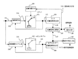
図1は、本発明の実施例を示すロボットの制御装置のブロック図である。
図において、101は制御対象とするロボット、102はロボット101を模擬したロボットモデル、103は制御演算部、104は制御演算モデル部、105はリンク位置姿勢算出部、106はモデルリンク位置姿勢算出部、107は位置姿勢比較部、108は装置保護手段、109は通知手段、110はロボットモデルの動作画像を提供する動作可視化手段である。また111はロボット101の目標関節変位量、112は関節変位量、113はモデル関節変位量、114はアクチュエータへの制御入力値、115はロボットモデルへの制御入力値、116は監視対象とする1つ以上のリンクの位置と姿勢を表すリンク位置姿勢、117はロボットモデル102における前記リンク位置姿勢に対応する信号であるモデルリンク位置姿勢、118は接触検出信号である。ロボットモデル102および制御演算モデル部104は、目標関節変位量111に対する関節変位量112の応答特性を模擬するように構成する。なお、ロボット101は、各関節のアクチュエータの出力を制御する手段と該各関節の変位量を計測する手段を有するものとなっている(何れも不図示)。
FIG. 1 is a block diagram of a robot control apparatus showing an embodiment of the present invention.
In the figure, 101 is a robot to be controlled, 102 is a robot model simulating the
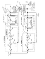
図2は図1に基づいてその詳細を説明するための制御系のブロック図を示したものである。すなわち、図1に示すロボット101、ロボットモデル102、制御演算部103、制御演算モデル部104の構成が、それぞれ図2における101’、102’、103’、104’の構成に対応している。
図2において、101’はn個の回転関節と各関節のトルクを制御可能なモータを有するロボットアーム、102’はロボットアーム101’の各関節トルクに対する関節角度の応答特性を模擬する1慣性系モデルをn個並べたアームモデル、103’はロボットアーム101’の各関節角度を制御するための制御演算部、104’は制御演算モデル部、105’は監視対象とするk個のリンク位置姿勢を計算する位置姿勢算出部、106’は監視対象のk個のリンク位置姿勢に対応するモデルリンク位置姿勢算出部、107’は位置姿勢比較部である。また108’はロボットを停止させるための装置保護手段となるブレーキ、109’は接触検出を操作者に伝えるためのアラーム、110’はモデルの動作を動画として提供するためのモニタである。
また、ブレーキ108’は、接触検出信号118’をうけると直ちにロボットアーム101’に停止信号を送り関節部の動作を停止させる。その結果、ロボットアームが動き続けて接触した周辺機器やロボットアーム自体の破壊を防止するようになっている。
また、アームモデル102’の動作はモニタ110’によって実時間表示し、操作者の状況把握を支援するようになっている。操作者自身がロボットアーム101’とアームモデル102’とを比較して異常を発見することができる他、接触検出時にはロボットがどのような動作をしようとした結果、接触が起こったのかを容易に知ることができる。また操作者とロボットとの距離が離れている場合でも、モニタ110’の表示によってロボットの動作状況がある程度把握できるようになっている。
FIG. 2 is a block diagram of a control system for explaining the details based on FIG. That is, the configurations of the
In FIG. 2, 101 ′ is a robot arm having n rotary joints and a motor capable of controlling the torque of each joint, and 102 ′ is a one-inertia system that simulates the response characteristics of the joint angle with respect to each joint torque of the
Further, when the brake 108 'receives the contact detection signal 118', it immediately sends a stop signal to the robot arm 101 'to stop the operation of the joint portion. As a result, the peripheral arm that the robot arm keeps moving and the destruction of the robot arm itself are prevented.
Further, the operation of the arm model 102 'is displayed on the monitor 110' in real time to assist the operator in grasping the situation. The operator can compare the
以下の説明のため、図中の信号の数式表現を与える。
111’はロボットアーム101’の関節角度指令であり
θr=[θ1 r,・・・,θn r]T ・・・(1)
と表現し、112’はロボットアーム101’の関節角度であり
θ=[θ1,・・・,θn]T ・・・(2)
と表現し、113’はモデルの関節角度であり
θm=[θ1 m,・・・,θn m]T ・・・(3)
と表現し、114’はモータへのトルク指令値であり
τ=[τ1,・・・,τn]T ・・・(4)
と表現し、115’はロボットモデルへのトルク入力値であり
τm−=[τ1 m,・・・,τn m]T ・・・(5)
と表現する。
116’は監視対象とするk個のリンクに関するリンクの位置及び姿勢でありリンクiの位置姿勢ベクトルを以下の式(6)で表わす。
X1,・・,Xk, Xi==[xi 1, xi 2, xi 3, xi 4, xi 5, xi 6]T, i=0,・・・,k ・・・(6)
117’はリンク位置姿勢116’に対応するモデルリンクの位置及び姿勢であり、モデルリンクの位置姿勢ベクトルを以下の式(7)で表わす。
Xm 1,・・・,Xm k, Xm i==[xi m1, xi m2, xi m3, xi m4, xi m5, xi m6]T, i=0,・・・,k ・・・(7)
とそれぞれ表現する。118’は接触検出信号である。また221はロボットアームの第1関節に印加するトルクであり、トルク指令値114’の第1成分である。222はロボットアームの第n関節に印加するトルクで、トルク指令値114’の第n成分である。223は関節角度112’の第1成分、224は第n成分である。225はロボットモデルへのトルク入力値115’の第1成分、226は第n成分である。227はモデルの関節角度113’の第1成分、228は第n成分である。
For the following description, a mathematical expression of the signal in the figure is given.
111 ′ is a joint angle command of the
112 ′ is a joint angle of the
113 ′ is the joint angle of the model, and θ m = [θ 1 m ,..., Θ n m ] T (3)
114 ′ is a torque command value to the motor, and τ = [τ 1 ,..., Τ n ] T (4)
115 ′ is a torque input value to the robot model, and τ m− = [τ 1 m ,..., Τ n m ] T (5)
It expresses .
1 16 'represented by the following formula the position and orientation vectors of the position and orientation of the link about the k links to be monitored link i (6).
X 1 ,..., X k , X i == [x i 1 , x i 2 , x i 3 , x i 4 , x i 5 , x i 6 ] T , i = 0,. (6)
1 17 'link position and orientation 116' is the position and orientation of the model links corresponding to, expressed by the following equation the position and orientation vectors of the model links (7).
X m 1, ···, X m k, X m i == [x i m1, x i m2, x i m3, x i m4, x i m5, x i m6] T, i = 0, ·· ., K (7)
Respectively. Reference numeral 118 'denotes a contact detection signal.
また、図2中の制御演算部103’において、201は位置制御ゲイン回路、202は微分器、203は速度制御ゲイン回路、204は出力制限器、205は重力・摩擦力補償器、206は出力変換定数回路である。このように制御演算部を構成することで、ロボットアーム101’は関節角度指令111に追従しようとする。しかし関節角度指令が急激に変化するときは、ロボットアーム101’が目標に対して遅れて追従する、すなわちサーボ遅れがあるため、一時的に関節角度指令111’と関節角度112’との差が増大することがある。
2, 201 is a position control gain circuit, 202 is a differentiator, 203 is a speed control gain circuit, 204 is an output limiter, 205 is a gravity / friction force compensator, and 206 is an output. It is a conversion constant circuit. By configuring the control calculation unit in this way, the
図2中のアームモデル102’において、211はロボットアームの第1関節の印加トルク指令に対する応答を模擬する1慣性系剛体モデルであり、212はロボットアームの第n関節の印加トルクに対する応答を模擬する1慣性系剛体モデルである。第i関節の1慣性系剛体モデルの入出力関係は次の式とする。
L(θi m)=1/(ji s2)・L(τi) i=0、・・・、n ・・・(8)
ここでL(・)は、ラプラス変換作用素を表し、sはラプラス変換のsである。Jiはロボットアームの第i関節まわりの等価慣性モーメントである。実際にはロボットアームの関節回りの慣性モーメントはアーム姿勢によって複雑に変化するが、モデルでは定数Jiで代表する。また、207から210は制御演算モデル部104を構成しており、207は位置制御ゲイン回路、208は微分器、209は速度制御ゲイン回路、210は出力制限器である。
In the arm model 102 'in FIG. 2, 211 is a one-inertia rigid body model that simulates the response to the applied torque command of the first joint of the robot arm, and 212 simulates the response of the robot arm to the applied torque of the nth joint. This is a one-inertia rigid body model. The input / output relationship of the 1-inertia rigid body model of the i-th joint is as follows.
L (θ i m ) = 1 / (j i s 2 ) · L (τ i ) i = 0,..., N (8)
Here, L (•) represents a Laplace transform operator, and s is Laplace transform s. J i is an equivalent moment of inertia around the i-th joint of the robot arm. Actually, the moment of inertia around the joint of the robot arm varies in a complicated manner depending on the arm posture, but the model represents it by a constant J i .
したがって、第1実施例に係るロボット制御装置は、上記のごとくアームモデル102’と制御演算モデル部104’を構成するようにしたので、制御演算部103’とロボットアーム101’における関節角度指令111’に対する関節角度112’の応答を模擬することができる。その結果、ロボットアームと周辺機器との接触が起こらなければ、モデルの関節角度113は関節角度112’にほぼ一致する。
図6は本発明の実施例を説明するための1つのリンクの1方向におけるロボットおよびロボットモデルの位置応答波形の例を示した図である。図において、601がモデル位置応答の波形である。仮に位置指令が急激に変化しても、位置応答とモデル位置応答との相違は僅かであるため誤検出は起こらない。ロボットアームが接触力を受けるとリンク位置姿勢116’はその影響を受けるが、モデルリンク位置姿勢117’は接触の影響を受けないため、両者の間に乖離が生じる。これを位置姿勢比較部で監視して接触検出をするのである。
Therefore, since the robot control apparatus according to the first embodiment is configured as the arm model 102 ′ and the control
FIG. 6 is a diagram showing examples of position response waveforms of the robot and robot model in one direction of one link for explaining the embodiment of the present invention. In the figure, reference numeral 601 denotes a model position response waveform. Even if the position command changes abruptly, there is little difference between the position response and the model position response, so no erroneous detection occurs. When the robot arm receives a contact force, the link position /
次に、本発明の第2実施例について説明する。
図3は、本発明の第2実施例を示す位置姿勢比較部105’のブロック図である(構成例1)。
以下ではロボットアーム101’のリンクのうち監視対象とするk個のリンクに1からkまでの番号をつけ、それぞれリンクi(i=0,・・・,k)のように表現する。構成例1では、位置姿勢比較部105’をリンク1の位置姿勢比較部からリンクkの位置姿勢比較部までを並列に並べたものとする。各リンクの位置姿勢比較部には対応するリンク位置姿勢とモデルリンク位置姿勢が入力され、並列に行われる比較演算の結果に基づいて接触検出信号を出力する。
図3において、301はリンク1の位置姿勢比較部、302はリンクiの位置姿勢比較部、303は絶対値計算手段、304は比較演算手段、311はリンク1の位置姿勢、312はリンクiの位置姿勢、313はリンクkの位置姿勢、314はモデルリンク1の位置姿勢、315はモデルリンクiの位置姿勢、316はモデルリンクkの位置姿勢、317はリンクiの位置姿勢偏差絶対値、318はリンクiの閾値
δii=1,・・・,k ・・・(9)
である。まず、入力されたリンクiの位置姿勢とモデルリンクiの位置姿勢との差をとり、絶対値計算手段303で次の式によりリンクiの位置姿勢偏差絶対値317を計算する。
| Xi− Xm i|=( Xi − Xm i ) T( Xi − Xm i )1/2 ・・・(10)
比較演算手段304ではリンクiの位置姿勢偏差絶対値317とリンクiの閾値318とを比較し、
δi<| Xi − Xm i| ・・・(11)
となったときに接触検出信号を出力する。
したがって、第2実施例は上記のように状態比較部105’を構成すれば、単純な演算によってロボットアームと周辺機器との接触を精度よく検出することができる。
Next, a second embodiment of the present invention will be described.
FIG. 3 is a block diagram of the position /
In the following, among the links of the
In FIG. 3, 301 is a position and orientation comparison unit of
It is. First, the difference between the input position and orientation of the link i and the position and orientation of the model link i is calculated, and the absolute value calculation means 303 calculates the
| X i - X m i | = (X i - X m i ) T (X i - X m i 1/2 ... (10)
The comparison calculation means 304 compares the
δ i <| X i - X m i | ··· (11)
When this happens, a contact detection signal is output.
Therefore, in the second embodiment, if the
図7はロボットアームの手先と周辺機器との間で接触が起こった場合の、ロボットアームモデルとの比較を示した模式図である。
図において、101’’は3リンクのロボットアーム、102’’は対応するアームモデル、701は周辺機器、711はリンク1の位置偏差絶対値、712はリンク2の位置偏差絶対値、713はリンク3の位置偏差絶対値である。
リンク3は周辺機器との接触の影響を受けるため、接触の影響を受けないモデルリンク3との乖離が大きくなっている。図では位置のみの偏差を表示しているが、リンクの姿勢についてもロボットアームとモデルとの乖離が生じている。偏差の絶対値が閾値を超えたときに接触検出信号が出力される。
FIG. 7 is a schematic diagram showing a comparison with a robot arm model when contact is made between the hand of the robot arm and a peripheral device.
In the figure, 101 ″ is a three-link robot arm, 102 ″ is a corresponding arm model, 701 is a peripheral device, 711 is a
Since the link 3 is affected by contact with peripheral devices, the divergence from the model link 3 that is not affected by contact is large. In the figure, the deviation of only the position is displayed, but the divergence between the robot arm and the model also occurs in the link posture. A contact detection signal is output when the absolute value of the deviation exceeds a threshold value.
次に、本発明の第3実施例について説明する(構成例2)。
図4は、本発明の第3実施例を示す状態比較部105’のブロック図である(構成例2)。
第3実施例が第2実施例と異なる点は、状態比較部105’において、ロボットアームとアームモデルの位置姿勢偏差を成分毎に計算し個別の閾値と比較する点である。なお、リンク1の位置姿勢比較部からリンクkの位置姿勢比較部までを並列に並べたものとするのは構成例1と同様である。
図4において、401はリンク1の位置姿勢比較部、402はリンクiの位置姿勢比較部、403は絶対値ベクトル計算手段、404は成分比較演算手段、411はリンクiの閾値ベクトル
[δxi 1,δxi 2, ・・・, δxi 6]T ・・・(12)
、412はリンクiの位置姿勢偏差絶対値ベクトル
[ |xi 1 − xi m1|, |xi 2− xi m2|,・・・, |xi 6 − xi m6|]T ・・・(13)
である。まず、入力されたリンクiの位置姿勢とモデルリンクiの位置姿勢との差をとり、絶対値ベクトル計算手段403で式13のようにリンクi位置姿勢偏差の各成分の絶対値を計算する。成分比較演算手段404ではリンクiの位置姿勢偏差絶対値ベクトル412とリンクiの閾値ベクトル411とを比較し、
δxi j<| xi − xi mj| ・・・(14)
がj=1,2,・・・,6のうち少なくとも1つについて満足される場合に接触検出信号を出力する。
したがって、第3実施例は上記のようにすれば、ある方向には感度よく接触を検出し、ある方向には接触を検出しないようにすることが可能となる。ロボットに周辺機器との接触を伴う作業を行わせる際には、作業に伴って接触が起こる向きの閾値を大きくして不要な接触検出が起きないようにし、作業に伴う接触が起こらない向きの閾値は通常通りとして予期せぬ接触を確実に検出するようにすればよい。
Next, a third embodiment of the present invention will be described (Configuration Example 2).
FIG. 4 is a block diagram of the
The third embodiment differs from the second embodiment in that the
In FIG. 4, 401 is a position and orientation comparison unit of
It is. First, the difference between the input position and orientation of the link i and the position and orientation of the model link i is calculated, and the absolute value vector calculation means 403 calculates the absolute value of each component of the link i position and orientation deviation as shown in
δx i j <| x i -x i mj | (14)
Is satisfied for at least one of j = 1, 2,..., 6, a contact detection signal is output.
Therefore, in the third embodiment, as described above, it is possible to detect contact in a certain direction with high sensitivity and not to detect contact in a certain direction. When the robot performs work that involves contact with peripheral devices, the threshold for the direction in which contact occurs with the work is increased so that unnecessary contact detection does not occur. The threshold may be set as usual and an unexpected contact may be reliably detected.
次に、本実施例が有するもう1つの効果を、図8を用いて説明する。
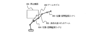
図8は多自由度のロボットアームにおける途中のリンクが周辺機器と接触した場合の、ロボットアームとの比較を示した模式図である。
図8において、801は冗長自由度を有する多自由度ロボットアーム、802は対応するアームモデル、803は位置・姿勢を監視するリンク1、804は位置・姿勢を監視するリンク2、805は周辺機器を表す。
周辺機器805との接触によってリンク804を含むロボットアーム801の一部がアームモデル802から大きく離れているが、リンク803についてはロボットアーム801とアームモデル802はほぼ一致している。
したがってリンク803のみ、すなわち手先のみの位置・姿勢監視では、図のような周辺機器との接触を検出することができない。しかし監視対象となるリンクを803と804の2つに増やし、位置・姿勢監視リンク2の位置・姿勢についても実機部とモデルとを比較・監視していれば、このような場合でもロボットアームと周辺機器との接触を高感度に検出することができる。その結果、ロボットアーム全体にわたって接触有無の監視ができ、関節角度や手先の位置・姿勢のみを監視する場合に比べて高感度に接触を検出できるのである。また、ロボットモデルは、実際にロボットを動作させる前にあらかじめロボットモデルにだけ指令を与えて位置に限らず速度やトルクなどが達成可能であるかを検証するのにも用いることができる。これにより、ロボットが予期せぬ動きをしないかを事前に確認できる。特に冗長自由度を持ったロボットにおける異常解による急激な動作の防止に有効である。
Next, another effect of the present embodiment will be described with reference to FIG.
FIG. 8 is a schematic diagram showing a comparison with a robot arm when a link in the middle of a multi-degree-of-freedom robot arm contacts a peripheral device.
In FIG. 8, 801 is a multi-degree-of-freedom robot arm having redundant degrees of freedom, 802 is a corresponding arm model, 803 is a
A part of the robot arm 801 including the link 804 is largely separated from the arm model 802 due to contact with the peripheral device 805, but the robot arm 801 and the arm model 802 are substantially coincident with each other regarding the link 803.
Therefore, only the link 803, that is, the position / posture monitoring of only the hand cannot detect contact with peripheral devices as shown in the figure. However, if the number of links to be monitored is increased to two, 803 and 804, and the position and orientation of the position / posture monitoring link 2 are compared and monitored with the actual unit and model, the robot arm Contact with peripheral devices can be detected with high sensitivity. As a result, the presence or absence of contact can be monitored over the entire robot arm, and contact can be detected with higher sensitivity than when only the joint angle and the position / posture of the hand are monitored. The robot model can also be used to verify whether speed, torque, and the like can be achieved in addition to the position by giving a command only to the robot model in advance before actually operating the robot. This makes it possible to confirm in advance whether the robot does not move unexpectedly. This is particularly effective in preventing sudden movements due to abnormal solutions in robots with redundant degrees of freedom.
最後に、本発明が従来技術2〜4に相当する特許文献1〜3と異なる点を以下に整理して述べる。
本発明が特許文献1と異なる点は次の2点である。
(1)ロボットを模擬するロボットモデルを備え、ロボットの応答とロボットモデルの応答とを比較するようにした点である。これにより、ロボットモデルを用いることによってロボットがあるべき状態をロボットモデルから得ることができ、それと実際のロボットの状態とを比較することで精度の高い接触検出が可能となる。
また、ロボットモデルではロボットの目標関節変位量に対する応答の遅れも模擬するため、指令が急激に変化することによって誤検出をし得るという特許文献1の方法の問題点を解決できる。
(2)位置姿勢比較部において、リンク位置姿勢のロボットモデルに対する差の監視を複数のリンクに対して行うようにした点である。これにより、ロボット全体の監視ができ、 手先以外の部分が接触した場合にも高感度な検出が可能である。
Finally, the points that the present invention differs from
The present invention differs from
(1) A robot model that simulates a robot is provided, and the response of the robot is compared with the response of the robot model. Thus, by using the robot model, the state where the robot should be can be obtained from the robot model, and the contact detection with high accuracy can be performed by comparing it with the actual state of the robot.
Further, since the robot model also simulates a response delay with respect to the target joint displacement amount of the robot, it is possible to solve the problem of the method of
(2) In the position / orientation comparison unit, the difference between the link position / orientation and the robot model is monitored for a plurality of links. As a result, the entire robot can be monitored, and highly sensitive detection is possible even when parts other than the hand touch.
本発明が特許文献2と異なる点は、オブザーバによる外乱力推定を行うことなく実機の応答とモデルの応答を比較することで接触検出を行う点である。これにより、比較に要する計算は非常に単純なものであり、少ない計算量で接触検出をすることができる。 The present invention is different from Patent Document 2 in that contact detection is performed by comparing the response of an actual machine and the response of a model without performing disturbance force estimation by an observer. Thereby, the calculation required for the comparison is very simple, and contact detection can be performed with a small amount of calculation.
本発明が特許文献3と異なる点は、ロボットを模擬するロボットモデルを備え、ロボットの応答とロボットモデルの応答とを複数リンクの位置姿勢について比較するようにした部分である。これにより、位置指令の急激な変化を誤検出してしまうという特許文献3の問題点は解決される。 The present invention differs from Patent Document 3 in that a robot model that simulates a robot is provided, and the response of the robot and the response of the robot model are compared with respect to the position and orientation of a plurality of links. This solves the problem of Patent Document 3 in which a sudden change in the position command is erroneously detected.
なお、第1実施例では、制御演算部103’と制御演算モデル部104’とが同じ構造を有する必要はなく、ロボットアーム101とアームモデル102とが厳密に一致している必要もない。関節角度指令111’に対するモデルの関節角度113’の応答特性が、関節角度指令111’に対する関節角度112’の応答特性を模擬できていればよい。
In the first embodiment, the
また、アラーム109’は、接触検出信号をうけるとアラームランプを点灯させ、操作者に接触検出を通知するものが使用されるが、ランプの他にブザー、操作パネル画面上の文字表示あるいは操作者が感知できるものであれば何でも良い。 The alarm 109 'is used to turn on an alarm lamp when a contact detection signal is received and notify the operator of contact detection. In addition to the lamp, a buzzer, a character display on the operation panel screen, or an operator is used. Anything that can be detected is acceptable.
ロボットと制御演算部を模擬するモデルを備え複数のリンクの位置姿勢についてロボットとロボットモデルとを比較することによって、目標関節変位量の変化に関係なく少ない計算量で接触検出ができ、また新たなセンサを必要としないので、多くの産業用ロボットやホームロボットなど、周辺環境との接触が起こり得るロボットに広く適用できる。 By comparing the robot and robot model for the position and orientation of multiple links with a model that simulates the robot and the control calculation unit, contact detection can be performed with a small amount of calculation regardless of changes in the target joint displacement, and a new Since it does not require a sensor, it can be widely applied to robots that can come into contact with the surrounding environment, such as many industrial robots and home robots.
101 ロボット
101’ ロボットアーム
101’’ 3リンクロボットアーム
102’、102’’、802 アームモデル
102 ロボットモデル
103、103’ 制御演算部
104、104’ 制御演算モデル部
105、105’ リンク位置姿勢算出部
106、106’ モデルリンク位置姿勢算出部
107、107’ 位置姿勢比較部
108 装置保護手段
108’ ブレーキ
109 通知手段
109’ アラーム
110 動作可視化手段
110’ モニタ
111 目標関節変位量
111’ 関節角度指令
112 関節変位量
112’ 関節角度
113 モデル関節変位量
113’ モデルの関節角度
114 アクチュエータへの制御入力値
114’ トルク指令値
115 ロボットモデルへの制御入力値
115’ ロボットモデルへのトルク入力値
116、116’ リンク位置姿勢
117、117’ モデルリンク位置姿勢
118、118’ 接触検出信号
201、207 位置制御ゲイン回路
202、208 微分器
203、209 速度制御ゲイン回路
204、210 出力制限器
205 重力・摩擦力補償器
206 出力変換定数回路
211 第1関節の印加トルクに対する応答を模擬する1慣性系剛体モデル
212 第n関節の印加トルクに対する応答を模擬する1慣性系剛体モデル
221 トルク信号114の第1成分
222 トルク信号114の第n成分
223 実機部の関節角度112の第1成分
224 実機部の関節角度113の第n成分
225 アームモデルへのトルク信号115の第1成分
226 アームモデルへのトルク信号115の第n成分
227 アームモデルの第1関節の角度
228 アームモデルの第n関節の角度
301、401 リンク1の位置姿勢比較部
302、402 リンクiの位置姿勢比較部
303 絶対値計算手段
304 比較演算手段
311 リンク1の位置姿勢
312 リンクiの位置姿勢
313 リンクkの位置姿勢
314 モデルリンク1の位置姿勢
315 モデルリンクiの位置姿勢
316 モデルリンクkの位置姿勢
317 リンクiの位置姿勢偏差絶対値
318 リンクiの閾値
403 絶対値ベクトル計算手段
404 成分比較演算手段
411 リンクiの閾値ベクトル
412 リンクiの位置姿勢偏差絶対値ベクトル
501 位置指令
502 位置応答
503 位置指令と位置応答との差の最大値
601 モデル位置応答
701 周辺機器805 周辺機器
711 リンク1の位置偏差絶対値
712 リンク2の位置偏差絶対値
713 リンク3の位置偏差絶対値
801 多自由度のロボットアーム
803 位置姿勢を監視するリンク1
804 位置姿勢を監視するリンク2
101 Robot 101 ′ Robot arm 101 ″ Three-link robot arm 102 ′, 102 ″, 802 Arm model 102 Robot model 103, 103 ′ Control calculation unit 104, 104 ′ Control calculation model unit 105, 105 ′ Link position / posture calculation unit 106, 106 ′ Model link position / orientation calculation unit 107, 107 ′ Position / orientation comparison unit 108 Device protection unit 108 ′ Brake 109 Notification unit 109 ′ Alarm 110 Operation visualization unit 110 ′ Monitor 111 Target joint displacement amount 111 ′ Joint angle command 112 Joint Displacement amount 112 'Joint angle 113 Model joint displacement amount 113' Model joint angle 114 Control input value 114 'to actuator 114 Torque command value 115 Control input value 115' to robot model Torque input value 116, 116 'to robot model Link position / posture 117, 17 'Model link position and orientation 118, 118' Contact detection signal 201, 207 Position control gain circuit 202, 208 Differentiator 203, 209 Speed control gain circuit 204, 210 Output limiter 205 Gravity / friction force compensator 206 Output conversion constant circuit 211 One-inertia rigid body model 212 that simulates response to applied torque of first joint 212 One-inertia rigid body model 221 that simulates response to applied torque of n-th joint First component 222 of torque signal 114 n-th component of torque signal 114 223 First component 224 of actual machine joint angle 112 224th nth component 225 of actual machine joint angle 113 First component 226 of torque signal 115 to arm model 227 nth component of torque signal 115 to arm model 227 First joint angle 228 nth joint angles 301, 40 of the arm model Link 1 position / orientation comparison unit 302, 402 Link i position / orientation comparison unit 303 Absolute value calculation unit 304 Comparison operation unit 311 Link 1 position / orientation 312 Link i position / orientation 313 Link k position / orientation 314 Model link 1 position Posture 315 Position / posture 316 of model link i Position / posture 317 of model link k Position / posture deviation absolute value 318 of link i Threshold value 403 of link i Absolute value vector calculation means 404 Component comparison calculation means 411 Threshold vector 412 of link i Position / attitude deviation absolute value vector 501 Position command 502 Position response 503 Maximum difference 601 between position command and position response Model position response 701 Peripheral device 805 Peripheral device 711 Link 1 position deviation absolute value 712 Link 2 position deviation absolute value 713 Link 3 absolute value of position deviation 801 Freedom robot arm 803 Link 1 for monitoring the position and orientation
804 Link 2 for monitoring the position and orientation
Claims (7)
前記アクチュエータへの制御入力値を計算し出力する制御演算部と、
前記ロボットを模擬するロボットモデルと、
前記制御演算部を模擬する制御演算モデル部と、
前記各関節の変位量に基づいて、前記ロボットの監視対象とする少なくとも1つ以上の前記リンクの位置および姿勢を算出するリンク位置姿勢算出部と、
前記ロボットモデルのモデル関節変位量に基づいて、前記監視対象とするリンクに対応するモデルリンクの位置および姿勢を算出するモデルリンク位置姿勢算出部と、
前記リンク位置姿勢算出部で算出した前記リンクの位置と、前記モデルリンク位置姿勢算出部で算出したモデルリンクの位置との偏差の絶対値が閾値を上回ったときに接触検出信号を出力する位置姿勢比較部と、を備えた
ことを特徴とするロボットの制御装置。 A control device for controlling a robot having a plurality of links, means for controlling the output of an actuator of a joint that moves the links, and means for measuring a displacement amount of each joint,
A control operation unit that calculates and outputs a control input value to the actuator;
A robot model for simulating the robot;
A control calculation model unit that simulates the control calculation unit;
A link position and orientation calculation unit that calculates the position and orientation of at least one of the links to be monitored by the robot based on the displacement amount of each joint;
A model link position / orientation calculating unit that calculates a position and orientation of a model link corresponding to the link to be monitored based on a model joint displacement amount of the robot model;
Position and orientation that outputs a contact detection signal when the absolute value of the deviation between the position of the link calculated by the link position and orientation calculation unit and the position of the model link calculated by the model link position and orientation calculation unit exceeds a threshold value And a control unit for the robot.
前記アクチュエータへの制御入力値を計算し出力する制御演算部と、
前記ロボットを模擬するロボットモデルと、
前記制御演算部を模擬する制御演算モデル部と、
前記各関節の変位量に基づいて、前記ロボットの監視対象とする少なくとも1つ以上の前記リンクの位置および姿勢を算出するリンク位置姿勢算出部と、
前記ロボットモデルのモデル関節変位量に基づいて、前記監視対象とするリンクに対応するモデルリンクの位置および姿勢を算出するモデルリンク位置姿勢算出部と、
前記リンク位置姿勢算出部で算出した前記リンクの位置および姿勢と、前記モデルリンク位置姿勢算出部で算出したモデルリンクの位置および姿勢とを比較して結果を出力する位置姿勢比較部と、を備え、
前記位置姿勢算出部は、監視対象とする前記リンクの位置および姿勢を示す6個の成分を有する位置姿勢ベクトルを算出し、
前記モデルリンク位置姿勢算出部は、前記モデルリンクの位置および姿勢を示す6個の成分を有するモデルリンク位置姿勢ベクトルを算出し、
前記位置姿勢比較部は、
前記リンク位置姿勢ベクトルの各成分と前記モデルリンク位置姿勢ベクトルの各成分との差の大きさを個別に監視し、それぞれの差の大きさのうち少なくとも1つの大きさが閾値を上回ったときに接触検出信号を出力する
ことを特徴とするロボットの制御装置。 A control device for controlling a robot having a plurality of links, means for controlling the output of an actuator of a joint that moves the links, and means for measuring a displacement amount of each joint,
A control operation unit that calculates and outputs a control input value to the actuator;
A robot model for simulating the robot;
A control calculation model unit that simulates the control calculation unit;
A link position and orientation calculation unit that calculates the position and orientation of at least one of the links to be monitored by the robot based on the displacement amount of each joint;
A model link position / orientation calculating unit that calculates a position and orientation of a model link corresponding to the link to be monitored based on a model joint displacement amount of the robot model;
A position and orientation comparison unit that compares the position and orientation of the link calculated by the link position and orientation calculation unit with the position and orientation of the model link calculated by the model link position and orientation calculation unit and outputs a result. ,
The position / orientation calculation unit calculates a position / orientation vector having six components indicating the position and orientation of the link to be monitored;
The model link position / orientation calculation unit calculates a model link position / orientation vector having six components indicating the position and orientation of the model link;
The position and orientation comparison unit
When the magnitude of the difference between each component of the link position and orientation vector and each component of the model link position and orientation vector is individually monitored, and at least one of the magnitudes of the differences exceeds a threshold value A robot control device that outputs a contact detection signal.
ことを特徴とする請求項1又は2に記載のロボットの制御装置。 A notification means for notifying an operator of the result according to the comparison result of the position / orientation comparison section, a stop means for stopping the robot, an operation command switching means for switching the operation command of the robot, or a control input switching means for switching the control input of the robot. The robot control device according to claim 1, wherein at least one of them is provided.
ことを特徴とする請求項1〜3のいずれか1項に記載のロボットの制御装置。 The robot control apparatus according to any one of claims 1 to 3, further comprising model motion visualization means that provides the operator with the motion of the robot model as an image in synchronization with the motion of the robot.
ことを特徴とする請求項1〜4のいずれか1項に記載のロボットの制御装置。 5. The robot control apparatus according to claim 1, wherein the robot model is configured by arranging one inertial system model in the same number as the number of joints of the robot. 6.
請求項1〜5のいずれか1項に記載のロボットの制御装置とを備えた
ことを特徴とするロボットシステム。 With robots,
A robot system comprising: the robot control device according to claim 1.
ことを特徴とする、請求項6記載のロボットシステム。 The robot system according to claim 6, wherein the robot has redundant degrees of freedom.
Priority Applications (1)
| Application Number | Priority Date | Filing Date | Title |
|---|---|---|---|
| JP2004306027A JP4577607B2 (en) | 2004-10-20 | 2004-10-20 | Robot control device and robot system |
Applications Claiming Priority (1)
| Application Number | Priority Date | Filing Date | Title |
|---|---|---|---|
| JP2004306027A JP4577607B2 (en) | 2004-10-20 | 2004-10-20 | Robot control device and robot system |
Publications (3)
| Publication Number | Publication Date |
|---|---|
| JP2006116635A JP2006116635A (en) | 2006-05-11 |
| JP2006116635A5 JP2006116635A5 (en) | 2007-09-13 |
| JP4577607B2 true JP4577607B2 (en) | 2010-11-10 |
Family
ID=36535003
Family Applications (1)
| Application Number | Title | Priority Date | Filing Date |
|---|---|---|---|
| JP2004306027A Expired - Fee Related JP4577607B2 (en) | 2004-10-20 | 2004-10-20 | Robot control device and robot system |
Country Status (1)
| Country | Link |
|---|---|
| JP (1) | JP4577607B2 (en) |
Families Citing this family (5)
| Publication number | Priority date | Publication date | Assignee | Title |
|---|---|---|---|---|
| JP5177008B2 (en) * | 2009-02-20 | 2013-04-03 | 株式会社安川電機 | Robot control device and robot |
| KR101145243B1 (en) | 2010-03-31 | 2012-05-24 | 한국과학기술연구원 | Restriction space calculation method using position sensors of multi degrees-of-freedom manipulator |
| EP2952300A1 (en) * | 2014-06-05 | 2015-12-09 | Aldebaran Robotics | Collision detection |
| JP2017177255A (en) | 2016-03-29 | 2017-10-05 | ソニー株式会社 | Control device and control method |
| CN115728786A (en) * | 2023-01-10 | 2023-03-03 | 北京华录高诚科技有限公司 | Beidou-based anti-collision method and system for large-scale port operation mechanical equipment |
Citations (3)
| Publication number | Priority date | Publication date | Assignee | Title |
|---|---|---|---|---|
| JP2002287816A (en) * | 2001-03-27 | 2002-10-04 | Yaskawa Electric Corp | Remote adjusting and diagnostic device |
| JP2003165079A (en) * | 2001-11-28 | 2003-06-10 | Nachi Fujikoshi Corp | Industrial robot |
| JP2004181543A (en) * | 2002-11-29 | 2004-07-02 | Nachi Fujikoshi Corp | Industrial robot and method for judging its abnormality |
Family Cites Families (8)
| Publication number | Priority date | Publication date | Assignee | Title |
|---|---|---|---|---|
| JPS62279409A (en) * | 1986-05-28 | 1987-12-04 | Nec Corp | Robot movement simulator |
| JPH01120607A (en) * | 1987-11-04 | 1989-05-12 | Mitsubishi Electric Corp | Motor controller |
| JP3269852B2 (en) * | 1992-05-29 | 2002-04-02 | 本田技研工業株式会社 | Posture stabilization control device for legged mobile robot |
| JP3025421B2 (en) * | 1995-06-14 | 2000-03-27 | 三菱電機株式会社 | Abnormality detection device for control system |
| JPH09261618A (en) * | 1996-03-21 | 1997-10-03 | Toshiba Corp | Remote controller |
| JP3566014B2 (en) * | 1997-02-13 | 2004-09-15 | 三菱電機株式会社 | Processing equipment |
| JPH10315173A (en) * | 1997-05-13 | 1998-12-02 | Sankyo Seiki Mfg Co Ltd | Abnormality detector for robot |
| JP3165087B2 (en) * | 1997-09-30 | 2001-05-14 | 株式会社不二越 | Industrial robot failure detection method |
-
2004
- 2004-10-20 JP JP2004306027A patent/JP4577607B2/en not_active Expired - Fee Related
Patent Citations (3)
| Publication number | Priority date | Publication date | Assignee | Title |
|---|---|---|---|---|
| JP2002287816A (en) * | 2001-03-27 | 2002-10-04 | Yaskawa Electric Corp | Remote adjusting and diagnostic device |
| JP2003165079A (en) * | 2001-11-28 | 2003-06-10 | Nachi Fujikoshi Corp | Industrial robot |
| JP2004181543A (en) * | 2002-11-29 | 2004-07-02 | Nachi Fujikoshi Corp | Industrial robot and method for judging its abnormality |
Also Published As
| Publication number | Publication date |
|---|---|
| JP2006116635A (en) | 2006-05-11 |
Similar Documents
| Publication | Publication Date | Title |
|---|---|---|
| US8812157B2 (en) | Robot system having error detection function of robot and control method thereof | |
| JP4550849B2 (en) | Mobile robot with arm | |
| KR101818858B1 (en) | Switching of a controller of a robot to a manual guide-operating mode | |
| US11548153B2 (en) | Robot comprising safety system ensuring stopping time and distance | |
| JP6445150B2 (en) | Method for controlling robot manipulator, computer system, digital recording medium, computer program product, computer program, apparatus and robot | |
| US11534918B2 (en) | Device and method for controlling cooperative robot | |
| EP4234180A2 (en) | Detecting collisions of robot arms | |
| US20190001504A1 (en) | Method For Detecting A Collision Of A Robot Arm With An Object, And A Robot With A Robot Arm | |
| JP2012051042A (en) | Robot system and robot control device | |
| KR20150080050A (en) | Collision sensing apparatus of articulated robot and method using the same | |
| JP2017100200A (en) | Robot control device for recording occurrence state of emergency stop of robot | |
| US20160089787A1 (en) | Robot controller | |
| JP2019098407A (en) | robot | |
| JP2012139772A (en) | Robot system and method of detecting abnormality of robot | |
| KR101329853B1 (en) | Collision detection system of manipulator using torque filtering and control system and method of manipulator using the same | |
| KR20190079322A (en) | Robot control system | |
| JP2019141967A (en) | Vibration analysis device and vibration analysis method | |
| JP6526097B2 (en) | Robot system | |
| JP7481097B2 (en) | Robot Control Device | |
| CN111823235A (en) | Collision detection method for picking mechanical arm | |
| JP4577607B2 (en) | Robot control device and robot system | |
| JP2006116635A5 (en) | ||
| JP4258718B2 (en) | Robot controller | |
| CN110914019A (en) | Robot stopping distance simulation method | |
| Motoi et al. | Experimental operability evaluation of remote control with force feedback for mobile robot |
Legal Events
| Date | Code | Title | Description |
|---|---|---|---|
| A521 | Written amendment |
Free format text: JAPANESE INTERMEDIATE CODE: A523 Effective date: 20070725 |
|
| A621 | Written request for application examination |
Free format text: JAPANESE INTERMEDIATE CODE: A621 Effective date: 20070725 |
|
| A977 | Report on retrieval |
Free format text: JAPANESE INTERMEDIATE CODE: A971007 Effective date: 20090305 |
|
| A131 | Notification of reasons for refusal |
Free format text: JAPANESE INTERMEDIATE CODE: A131 Effective date: 20090311 |
|
| A521 | Written amendment |
Free format text: JAPANESE INTERMEDIATE CODE: A523 Effective date: 20090413 |
|
| A131 | Notification of reasons for refusal |
Free format text: JAPANESE INTERMEDIATE CODE: A131 Effective date: 20100302 |
|
| A521 | Written amendment |
Free format text: JAPANESE INTERMEDIATE CODE: A523 Effective date: 20100407 |
|
| A131 | Notification of reasons for refusal |
Free format text: JAPANESE INTERMEDIATE CODE: A131 Effective date: 20100510 |
|
| A521 | Written amendment |
Free format text: JAPANESE INTERMEDIATE CODE: A523 Effective date: 20100628 |
|
| TRDD | Decision of grant or rejection written | ||
| A01 | Written decision to grant a patent or to grant a registration (utility model) |
Free format text: JAPANESE INTERMEDIATE CODE: A01 Effective date: 20100730 |
|
| A01 | Written decision to grant a patent or to grant a registration (utility model) |
Free format text: JAPANESE INTERMEDIATE CODE: A01 |
|
| A61 | First payment of annual fees (during grant procedure) |
Free format text: JAPANESE INTERMEDIATE CODE: A61 Effective date: 20100812 |
|
| FPAY | Renewal fee payment (event date is renewal date of database) |
Free format text: PAYMENT UNTIL: 20130903 Year of fee payment: 3 |
|
| R150 | Certificate of patent or registration of utility model |
Free format text: JAPANESE INTERMEDIATE CODE: R150 |
|
| FPAY | Renewal fee payment (event date is renewal date of database) |
Free format text: PAYMENT UNTIL: 20140903 Year of fee payment: 4 |
|
| LAPS | Cancellation because of no payment of annual fees |