JP4571332B2 - Electronic device integration apparatus, computer terminal, and home information system - Google Patents
Electronic device integration apparatus, computer terminal, and home information system Download PDFInfo
- Publication number
- JP4571332B2 JP4571332B2 JP2001118123A JP2001118123A JP4571332B2 JP 4571332 B2 JP4571332 B2 JP 4571332B2 JP 2001118123 A JP2001118123 A JP 2001118123A JP 2001118123 A JP2001118123 A JP 2001118123A JP 4571332 B2 JP4571332 B2 JP 4571332B2
- Authority
- JP
- Japan
- Prior art keywords
- computer terminal
- sensor
- menu screen
- terminal
- communication interface
- Prior art date
- Legal status (The legal status is an assumption and is not a legal conclusion. Google has not performed a legal analysis and makes no representation as to the accuracy of the status listed.)
- Expired - Fee Related
Links
Images


Landscapes
- Management, Administration, Business Operations System, And Electronic Commerce (AREA)
- Computer And Data Communications (AREA)
- Small-Scale Networks (AREA)
- Selective Calling Equipment (AREA)
- Telephonic Communication Services (AREA)
Description
【発明の属する技術分野】
【0001】
本発明は、家庭のネットワーク化を容易にする技術に関する。
【従来の技術】
【0002】
近年急速に進む社会のネットワーク化や情報化は、家庭生活にも影響を及ぼしている。例えば、家庭内PC(パーソナルコンピュータ)や携帯電話からインターネットに接続し、様々な情報やサービスを利用することは当たり前になりつつある。携帯電話やPHSを各家族の構成員がそれぞれ持ち歩き、家族同士でいつでもどこでも気軽に連絡を取ることもできる。家庭内PCについても携帯電話、オーディオ機器、テレビなどと同様に、一家に一台の時代から、家族の構成員がそれぞれのPCを所有する時代に移行しつつある。
【0003】
また、本来アナログデータである音声や画像のディジタル通信が普及し、家庭内情報機器同士をIEEE1394などにより接続し、高速かつ大量のディジタルデータを機器間で伝送することが可能となってきている。このような背景から、家庭での情報機器の利用形態にも様々な変化が起こると予想される。例えば、ディジタルビデオやディジタルカメラで撮影したディジタルデータをPCに取り込んで処理することができるようになっているが、今後は旅先で撮影したビデオを、ビデオ端末から家族のPCへ電子メールで送り、家族は受信した映像や音声を家庭のディジタルTVで再生する、といった利用形態も想定される。
【0004】
さらに、CO2の削減やオゾン層の保護、高齢化に伴う安全な社会づくりなど数々の問題が、世界的に問題となっている。これらの問題を効果的に解決する1つの手段として、家電機器をECHONETにより接続し、複数の機器を統合して制御することが提案されている。ECHONETを用いれば、電灯線、小電力無線、赤外線、ツイストペア線など従来からあるインフラを用い、電灯、冷蔵庫、オーディオ機器、電子レンジ、風呂、空調機などの複数の家電機器、各種センサを用いた医療機器やセキュリティ機器を新たなネットワーク配設工事なしに接続し、ON/OFF、温度調整、時間調整などのコントロールをすることができる。
【発明が解決しようとする課題】
【0005】
将来、様々な家電機器や情報機器が家庭内に導入され、それぞれの機器がIEEE1394やECHONET、インターネットなど異なるネットワークに接続されるようになると、家庭内や家族間で使用する各種機器を統合して制御したいというニーズが生じると予想される。本発明は、電化・情報化が家庭にまで及んだ場合に、家庭内における情報サービスの利用や家庭内の各種機器の利用を統合する家庭内情報網の構築技術を提供することを目的とする。また、本発明は、電化・情報化が家庭まで及んで家族構成員が各自の機器を利用する場合に、煩雑な環境設定を必要とすることなく構成員の機器を接続し、容易に家庭内情報網を構築する技術を提供することを目的とする。
【課題を解決するための手段】
【0006】
前記課題を解決するために、本願第1発明は、
・公共ネットワークに接続するための外部接続手段と、
・少なくともディスプレイと入力手段とを有する1または複数のコンピュータ端末と通信するための第1通信インターフェースと、
・互いに接続された複数の電気機器と通信し、前記コンピュータ端末の入力手段からの入力内容に従い前記電気機器を制御するための第2通信インターフェースと、
・異なるエリアに取り付けられ、前記コンピュータ端末を検出するための第3通信インターフェースを有するセンサ群を識別するセンサ識別情報群と、前記センサ群に含まれる各センサが取り付けられているエリアに応じて設定されるメニュー画面データ群と、を記憶する記憶手段と、
・前記センサ群に含まれる第1センサにより検出された第1コンピュータ端末から、前記第1センサを識別する第1センサ識別情報及び前記第1コンピュータ端末を識別する第1端末識別情報を受信し、前記受信した情報に基づいて前記第1コンピュータ端末が位置するエリアを判別し、前記第1センサ識別情報に対応する第1メニュー画面データを前記メニュー画面データ群から抽出し、前記第1コンピュータ端末に提供するメニュー画面データを決定するメニュー決定手段と、
・前記メニュー決定手段により決定されたメニュー画面データを、前記コンピュータ端末に提供するテキストデータ及び静止画像データとして管理する管理手段と、
・前記テキストデータ及び/または静止画像データを、前記コンピュータ端末のディスプレイに表示可能な形式で、前記コンピュータ端末に提供する提供手段と、
を備える電子機器統合装置を提供する。
【0007】
この装置は、家庭内ネットワークを統合して家庭内情報網を構築し、かつ公共ネットワークと家庭内情報網とのゲートウェイとして機能する。公共ネットワークとしては、CATV網、ディジタルテレビ網等の放送網、ラジオ放送、光通信網、移動体通信網、公衆電話回線網を例示することができる。公共ネットワークに接続するための外部接続手段としては、CATVネットワークに接続するためのCATVモデム及びCATVチューナ、TVチューナ、公衆電話回線網に接続するためのADSLモデム、PHS網に接続するためのPHS、IMT2000等の携帯電話網に接続するための携帯電話などが挙げられる。
【0008】
電灯、冷蔵庫、テレビ、温水器などの家庭内電気機器は、ECHONETやIEEE1394などの通信インターフェースで互いに接続されている。本装置は、これらの電気機器同士を接続している通信インターフェースと同一のインターフェースを、第1通信インターフェースとして有している。
【0009】
また、本装置は、例えばタッチパネルを兼用するディスプレイにCPUが内蔵されたコンピュータ端末に接続するための第2通信インターフェースを有している。第2通信インターフェースとしては、IEEE1394、Bluetooth(商標出願中)、IEEE802.11bなどを挙げることができる。
【0010】
さらに本装置は、WWWサーバなどの管理手段により、テキストデータ及び静止画像データを管理し、これらのデータをコンピュータ端末に提供する。提供されるデータとしては、公共ネットワーク上のWWWサイトから取得するコンテンツや、本装置の提供者が用意する各種メニュー画面などが考えられる。また、提供されるデータは、コンピュータ端末上で表示可能な形式に加工される。
【0011】
例えば、本装置のWWWサーバは、電気機器を制御するためのメニュー画面を蓄積し、コンピュータ端末にこれを提供する。コンピュータ端末にWWWブラウザがない場合、提供手段がWWWブラウザをコンピュータ端末に提供する。ユーザがコンピュータ端末のディスプレイ上でメニュー画面に従って入力を行うと、入力内容が本装置から電気機器へ第1通信インターフェースを介して送信される。これにより、本装置を介してコンピュータ端末から電気機器を統括的に制御することができる。
【0012】
また例えば、本装置は、第1通信インターフェースによりコンピュータ端末の一種であるバイタルセンサと通信可能である。ユーザは、バイタルセンサにより体温や血圧を測定し、測定結果を本装置上のWWWサーバや公共ネットワークを介して接続されるサービスセンタに記録し、他のコンピュータ端末、例えばPCで体温の変化グラフを見ることができる。
【0013】
また例えば、本装置上のWWWサーバ(あるいはPROXYサーバ)は、公共ネットワーク上の各種WWWサイトへのアクセス要求を受け付ける初期メニュー画面を蓄積している。この画面を表示されたコンピュータ端末からあるサイトへのアクセス要求を受け取ると、WWWサーバは指定サイトにアクセスしてコンテンツを取得し、要求元端末に提供する。提供手段は、WWWブラウザが搭載されていないコンピュータ端末に対しては、WWWブラウザ及びコンテンツを提供する。目的とするコンテンツをコンピュータ端末上で参照したユーザは、そのコンテンツをWWWサーバに記録することができる。
【0014】
また例えば、本装置は、コンピュータ端末上にディジタルテレビの画像を表示させたり、コンピュータ端末からの入力に従いディジタルテレビにコンピュータ端末からの出力情報を表示させることもできる。
【0015】
このようにして、ユーザは、コンピュータ端末を操作することにより、本装置を介して公共ネットワークと情報を送受信したり、家庭内の電気機器をコントロールしたりすることが可能となる。
【0016】
さらに、この装置は、コンピュータ端末の移動に応じて、コンピュータ端末のメニュー画面を切り替える。センサとしては、赤外線センサ、bluetooth、PHS無線などによりコンピュータ端末と通信可能な無線機能を内蔵した機器(赤外線センサ、AV器機、家電等)を挙げることができる。センサは、例えば家庭においては、台所、居間、寝室、子供部屋などの天井に取り付けられる。各センサはセンサIDで特定される。
【0017】
本装置は、コンピュータ端末に提供するためのメニュー画面データを、部屋別に用意している。例えば、台所にあるコンピュータ端末には、「献立ボタン」、「ショッピングボタン」、「家計簿ボタン」、「家電制御ボタン」が表示される。「家電制御ボタン」を押すと、台所にある電気機器のリストが表示され、これらの機器を制御することができる。また居間にあるコンピュータ端末には、「本日のテレビボタン」、「カルチャーボタン」、「趣味娯楽ボタン」、「家電制御ボタン」が表示される。居間で「家電制御ボタン」を押すと、居間にある電気機器のリストが表示される。
ユーザがコンピュータ端末T001を持って台所に行くと、台所のセンサS001と端末T001とが無線通信を行う。端末T001はセンサS001を検出すると、本装置にセンサID“S001”、端末ID“T001”を通知する。本装置は、コンピュータ端末T001の位置をセンサID“S001”から“台所”であると決定し、T001に台所用メニュー画面を提供する。
【0018】
本願第2発明は、前記第1発明において、前記管理手段が、前記電気機器及びコンピュータ端末を制御するための第1メニュー画面データと、前記公共ネットワーク上で提供される情報を取得するための第2メニュー画面データとを、さらに蓄積している電子機器統合装置を提供する。
【0019】
例えばこの装置は、前記コンピュータ端末のディスプレイに、家庭内の電気機器や他のコンピュータ端末をコントロールするための家電制御メニュー(第1メニュー画面データ)と、インターネット上のウェブサイトにアクセスするためのサービスアクセスメニュー(第2メニュー画面データ)とを表示する。従って、ユーザは、一つのコンピュータ端末を用い、家庭内の電気機器にも家庭外のネットワークサービスにも、アクセスすることができる。
【0020】
本願第3発明は、公共ネットワーク、電気機器接続用ネットワーク及びコンピュータ接続用ネットワークに接続されたホームサーバに接続するためのコンピュータ端末を提供する。このコンピュータ端末は、
A;ディスプレイと、
B;入力手段と、
C;前記ホームサーバに接続するための第1通信インターフェースと、
D;異なるエリアに取り付けられたセンサ群からの信号を検出するための第3通信インターフェースと、
E;前記ホームサーバに接続されている電気機器及び他のコンピュータ端末を制御するための第1メニュー画面データと、前記公共ネットワーク上で提供される情報を取得するための第2メニュー画面データとを、前記ホームサーバから取得して前記ディスプレイ上に表示する表示制御手段と、
を少なくとも有している。
【0021】
前記表示制御手段は、前記第3通信インターフェースを介して前記センサ群に含まれる1または複数のセンサからの信号を待機し、受信した信号及びその強度に基づいていずれかのセンサの識別子を特定し、特定したセンサ識別子を前記ホームサーバに送信し、送信したセンサ識別子に応じた前記第1メニュー画面を取得する。
【0022】
本願第4発明は、
A;少なくともディスプレイ、入力手段及び第1通信インターフェースを有する、1または複数のコンピュータ端末と、
B;第2通信インターフェースを有する複数の電気機器と、
C;電子機器統合装置と、
を備える家庭内情報システムを提供する。
【0023】
電子機器統合装置は、下記C1〜C7を有する。
C1;公共ネットワークに接続するための外部接続手段、
C2;前記コンピュータ端末と通信するための第1通信インターフェース、
C3;前記複数の電気機器と通信し、前記コンピュータ端末からの入力内容に従い前記電気機器を制御するための第2通信インターフェース、
C4;異なるエリアに取り付けられ、前記コンピュータ端末を検出するための第3通信インターフェースを有するセンサ群を識別するセンサ識別情報群と、前記センサ群に含まれる各センサが取り付けられているエリアに応じて設定されるメニュー画面データ群と、を記憶する記憶手段、
C5;前記センサ群に含まれる第1センサにより検出された第1コンピュータ端末から、前記第1センサを識別する第1センサ識別情報及び前記第1コンピュータ端末を識別する第1端末識別情報を受信し、前記受信した情報に基づいて前記第1コンピュータ端末が位置するエリアを判別し、前記第1センサ識別情報に対応する第1メニュー画面データを前記メニュー画面データ群から抽出し、前記第1コンピュータ端末に提供するメニュー画面データを決定するメニュー決定手段、
C6;前記メニュー決定手段により決定されたメニュー画面データを、前記コンピュータ端末に提供するテキストデータ及び静止画像データとして管理する管理手段、
C7;前記テキストデータ及び/または静止画像データを、前記コンピュータ端末のディスプレイに表示可能な形式で、前記コンピュータ端末に提供する提供手段。
【発明の実施の形態】
【0024】
<発明の概要>
本発明においては、ECHONETなど(第2通信インターフェース)により接続された家庭内の家電製品(電気機器)群と、Bluetooth、IEEE802.11b、IEEE1394など(第1通信インターフェース)で接続された情報機器群とを、ホームサーバ(電子機器統合装置)により統合し、家庭内情報網を構築する。ここでいう情報機器には、家庭の構成員(以下、単にユーザという)が各自用いる有線接続型PC、PHS、バイタルセンサなど、入出力機能を有する情報機器(以下、単にコンピュータ端末という)が含まれる。また、ディジタルテレビ、ディジタルカメラ、ディジタルVHS、プリンタ、スキャナなど、入力機能のみまたは出力機能のみを有する情報機器も、ホームサーバに接続することができる。ホームサーバは、各種機器に対応したインターフェースを有しているので、家電製品や情報機器を容易にホームサーバに接続できる。これにより、異なる通信インターフェースを有する家庭内の家電製品及び情報機器をホームサーバを介して接続し、ホームサーバを中心とした家庭内情報網を容易に構築することができる。
【0025】
また、このホームサーバは、インターネット、CATV網、BSディジタル放送等の放送網、ラジオ放送網、移動体通信網、公衆電話回線網などの公共ネットワークへ接続するためのモデムやチューナを有している。従って、ホームサーバを経由して情報機器から公共ネットワークへ接続することができる。
【0026】
さらに、家庭内の各部屋にセンサを設け、情報機器とセンサとの間で無線通信を行い、ユーザの持ち歩く情報機器の位置をホームサーバにより管理することが好ましい。センサと情報機器との無線通信には、例えば赤外線通信を用いる。
【0027】
このホームサーバ及び家庭内情報網は、次のように作用する。ホームサーバは、家電製品や情報機器を操作するメニュー画面を、コンピュータ端末に提供する。ユーザは、一つのコンピュータ端末を操作するだけで、家電製品や、自分が使用中のまたは他のユーザが使用中の情報機器を制御することができる。さらに、ホームサーバは、インターネット上のWWWページのコンテンツ、CATVのコンテンツなど、公共ネットワーク上で提供される情報やこれらの情報へアクセスするためのメニュー画面を、コンピュータ端末に提供する。従って、ユーザは、一つのコンピュータ端末上で、電気機器を操作したり、公共ネットワーク上の情報を取得したりすることができる。
【0028】
また、センサを用いることにより、コンピュータ端末の位置に応じたメニュー画面がホームサーバから提供される。例えば、居間に位置するコンピュータ端末には、居間にある家電製品の制御ボタン、本日のテレビ番組情報にアクセスできるボタン、趣味娯楽情報にアクセスできるボタンなどが提供される。このコンピュータ端末を持ったユーザが台所に移動すると、台所にある電気機器の制御ボタン、一週間の献立が表示されるボタン、食材オンラインショッピングのボタンなどが提供される画面に切り替わる。
【0029】
<第1実施形態例>
次に、本発明のホームサーバ及びコンピュータ端末を用いて構成される家庭内情報網について、具体的に説明する。
【0030】
(1)全体構成
図1は、本発明にかかるホームサーバ及びコンピュータ端末を用いた家庭内情報網の構成を示す。この家庭内情報網は、ホームサーバ1、家電製品群2、情報機器群3、Irセンサ群4、電話機/FAX5、VOIP電話機6、有線接続型PC7、PHS親機を含むWHM8(Wat Hour Meter)が含まれている。また、ホームサーバ1は、公共ネットワーク9に接続されている。
【0031】
このホームサーバ1と家電製品群2とはECHONETにより、ホームサーバ1と情報機器群3とはBluetoothや無線LAN等により、それぞれ接続されている。
【0032】
家電製品群2に含まれる各製品は、家電製品同士及びホームサーバ1と接続するためのECHONETインターフェースを有している。家電製品群2には、一般家庭で用いられる家電、例えば、電灯、ディジタルテレビ、ステレオ、空調機、電子レンジ、冷蔵庫、お風呂のお湯張り機能、温水器が含まれる。
【0033】
情報機器群3に含まれる機器は、ホームサーバ1と接続するための無線I/F(Bluetooth I/Fや無線LAN等)を有している。また、情報機器群3には、タッチパネルを兼ねたディスプレイ、スピーカ、カメラ、マイク及びバッテリをさらに備えたコンピュータ端末(以下、複合端末という)31a,bが含まれる。複合端末31a,bは、例えば13インチや5インチ相当のディスプレイ兼タッチパネルを用いて構成され、ユーザが家の中で持ち歩いて使用するのに適している。また、ディジタルテレビ、PHS、携帯電話、プリンタ、スキャナ、体温や血圧などを測定するバイタルセンサなども情報機器群としてホームサーバ1に接続されている。これらの情報機器群3の中でも、ユーザの移動に伴って移動する機器、例えば複合端末やPHSは、Irセンサ4と通信するための赤外線通信I/Fをさらに有している。複合端末の機能構成については後述する。
【0034】
Irセンサ4は、家庭内の各エリア毎に取り付けられている。またIrセンサ4は、赤外線I/Fを有しており、複合端末31a,bと通信可能である。具体的には、Irセンサ4は、各Irセンサを特定するセンサIDを発信している。エリアとは、例えば居間、台所、各個室などであり、各エリアはIrセンサ4の赤外線到達範囲となるように設定される。
【0035】
電話機/FAX5は、ホームサーバ1を介して従来からある公衆電話回線網に接続される。VOIP電話機6は、TCP/IPに基づいて音声パケットを送受信し、音声の入出力を行う電話機である。このVOIP電話機6は、ホームサーバ1を介してインターネットや移動体通信網に接続されるか、あるいは直接インターネットや移動体通信網に接続される。有線接続型PC7は、デスクトップ型PCやノートブック型PCを含み、前記複合端末31a,bに比して大型で常時携帯するには不向きな情報機器、もしくは、キーボード入力等パソコン操作に長けた人が利用する情報機器である。WHM8は、電力使用量や水道使用量、ガス使用量などをメータから読み取り、読みとったデータをPHSにより所定の検針センターに送信する。
【0036】
(2)ホームサーバの構成及び機能
ホームサーバ1は、ECHONETインターフェース(図中I/F)11、無線(Bluetooth、IEEE1394、無線LAN等)I/F12、ADSLモデム13、CATVモデム14、テレビ/BS/CATVチューナ(以下、単にチューナという)15、PHS子機16、動画コーデック17、VOIPコーデック18、VODサーバ19、WWWサーバ110(あるいはPROXYサーバ)及び制御部111を有している。
【0037】
ECHONETインターフェース11及び無線I/F12は、それぞれ家電製品群2及び情報機器群3に接続するための通信インターフェースである。家電製品群2と接続するための通信インターフェースとしては、ECHONETに限定されない。例えば、より大容量のデータを通信する必要が生じた場合、IEEE1394などを用いても良い。同様に、ホームサーバと情報機器群との間の通信インターフェースとしては、Blutoothに限定されないが、テキストだけでなく音声や動画像通信も行える高速で大容量の通信を可能とする無線通信インターフェースが好ましい。例えばIEEE802.11bを挙げることができる。
【0038】
ADSLモデム13、CATVモデム14及びPHS子機16は、全て必須ではないが、公共ネットワーク9に接続するための手段として少なくとも1つは必要である。例えば、CATVモデム14にはVOIP電話機6や有線接続型PC7が接続され、CATV網を介してインターネットに接続する。ADSLモデム13には、電話機/FAX5が接続され、公衆電話回線に接続する。PHS子機16は、PHSの親機を兼ねるWHM8を介し、PHS網に接続する。
【0039】
チューナ15は、必ずしも必要ではないが、例えばCATV網により提供されるテレビ番組を、ホームサーバ1を介して、例えば複合端末上や通常のテレビ端末(図示せず)で出力するために用いられる。
【0040】
動画コーデック17は、必ずしも必要ではないが、例えばディジタルテレビ用のテレビ番組を、ディジタルテレビや複合端末上で出力するために用いられる。動画コーデック17は、チューナ15を介して受信した動画パケットを分解し、デジタル画像データを取り出し、無線I/F12を介してデジタルテレビや複合端末にディジタル画像データを送信する。
【0041】
VOIPコーデック18は、必ずしも必要ではないが、例えば複合端末31a,bをPHSとして用いる場合に必要となる。複合端末のマイクから入力されたユーザのアナログ音声データは、複合端末上でA/D変換され、ディジタル音声データとなってホームサーバ1に送信される。VOIPコーデック18は、無線I/F12を介して受信したディジタル音声データを音声パケット化し、PHS子機16を介して公共ネットワーク9に送出する。
【0042】
VODサーバ19は、必ずしも必要ではないが、複合端末31a,bに接続されたカメラから入力される動画像や、複合端末31a,bに接続されたマイクから入力される音声、チューナ15を介して受信するディジタルテレビ番組の動画像及び音声などを、ホームサーバ1上に蓄積されたコンテンツを表示するために用いられる。なお、動画像や音声のデータを蓄積、配信及び管理できる手段であれば、VODサーバに限定されない。
【0043】
WWWサーバ110は、複合端末31a,bに提供するテキスト及び静止画像データを蓄積、配信及び管理するための手段としてホームサーバ1に必須の機能である。例えば、WWWサーバ110は、家族の予定を書き込むためのカレンダーを保持し、そのカレンダーへの入力を複合端末31a,bや有線接続型PC7、PHS(以下、単に複合端末などという)から受け付ける。また、WWWサーバ110は、公共ネットワーク9上の情報、例えばウェブページへのアクセスを要求するためのメニューボタンやリンクを、複合端末などに提供する(後述する図7〜図11参照)。さらに、WWWサーバ110は、電気製品群3を制御するためのメニューボタンを、複合端末などに提供する(後述する図8〜図11参照)。これらカレンダーやメニューボタンは、ホームサーバ1の提供者がユーザに提供する前にユーザの利用方法に適した画面にカスタマイズし、WWWサーバ110に記録しておく。
【0044】
制御部111は、家電製品群2を制御するためのコマンドをWWWサーバ110を介して複合端末などから受け取り、ECHONETインターフェース11を介して対象の家電製品に送出する。また、制御部111は、起動した複合端末などに初期メニュー画面を提供する。さらに制御部111は、Irセンサ群4により検出される複合端末31a,bやPHSの位置情報に基づき、送信するメニュー画面を切り替える。メニュー画面の切り替え処理については、後述する。
【0045】
さらに、ホームサーバは、音声応答のための音声認識処理部(図示しない)や、パーソナルコンピュータの画像をテレビに出力するためのダウンコンバータ(図示しない)を備えていてもよい。
【0046】
(3)複合端末の構成及び機能
図2は、複合端末31a,bの機能ブロック図である。複合端末31a,bは、情報機器群3に含まれ、無線(Bluetooth)I/F(第1通信インターフェース)301及び赤外線I/F302(第3通信インターフェース)に加え、タッチパネルを兼ねるディスプレイ303(入力手段及びディスプレイ)、スピーカ304、カメラ305、マイク306、動画コーデック307及び表示制御部308を有している。また、複合端末31a,bは、WWWサーバから送られてくる信号とテレビ信号とを混合するための混合器311を有すると好ましい。複合端末上でテレビ映像を表示したり、ディジタルテレビを複合端末のディスプレイとして用いたりするためである。
【0047】
前述したように、無線I/F301及び赤外線I/F302は、それぞれホームサーバ1及びIrセンサ群4と通信するために必要である。また、タッチパネル兼ディスプレイ303は、ホームサーバ1から提供されるメニュー画面を出力したり、家電製品群2を制御するための入力や、公共ネットワーク上の情報へのアクセス要求を受け付ける。スピーカ304は音声出力手段として、カメラ305及びマイク306は、それぞれ画像及び音声入力手段として機能する。カメラ305は、撮影の自由度を持たせるために、複合端末31a,bにケーブルなどで接続されている。もちろん、カメラ305が複合端末装置に内蔵されていてもよい。動画コーデック307は、入力された動画像を動画パケット化してホームサーバ1に送信する機能を有する。
【0048】
なお、図示しないが、スピーカ304には、圧縮符号化された音声を復号化及び伸長する復号化器、ディジタル音声データをアナログ変換するD/A変換器及び増幅器が含まれている。カメラ305には、撮影された画像をディジタル変換するA/D変換器及び動画を圧縮する動画圧縮符号化器が含まれている。マイク306には、入力された音声をディジタル変換するA/D変換器と、音声を圧縮符号化する音声圧縮符号化器とが含まれている。
【0049】
表示制御部308は、複合端末31a,bが起動された段階で、ホームサーバ1にアクセスし、初期メニュー画面を取得する。初期メニュー画面としては、例えば家族の予定を書き込むカレンダーを含む画面が挙げられる(後述する図7参照)。また、表示制御部308は、一定時間毎にホームサーバ1にアクセスし、複合端末31a,bが位置するエリアに応じたメニュー画面データを取得する。
【0050】
なお、表示制御部308は、ホームサーバ1のWWWサーバ110に対応してWWWブラウザを有していても、また有していなくても良い。同様に、表示制御部308は、動画像を表示するためのアプリケーションを有していても良いし、有していなくても良い。ホームサーバ1は、複合端末31a,bの機能に応じた形式でデータを送信する。
【0051】
(4)処理の流れ
前述したように、ホームサーバ1は、制御部111により、複合端末31a,bにメニュー画面データを提供し、複合端末の位置によりメニュー画面を切り替える処理を行う。なお、メニュー画面を提供する情報機器としては、ユーザが持ち歩き、入出力機能を有する情報機器、例えばPHS、バイタルセンサなどでも良く、複合端末だけに限定されない。以下では、説明を容易にするため、複合端末を例に挙げて説明する。
【0052】
(4−1)テーブル
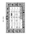
図3は、制御部111が有するテーブル群に蓄積される情報の概念説明図である。図3(a)はメニュー遷移テーブルの概念説明図である。このテーブルには、センサIDと、部屋IDと、メニューIDとが記憶されている。センサIDは、Irセンサ群4に含まれる各センサを特定するための識別情報である。部屋IDは、家の中をエリア毎に区切った場合の各エリアを特定する識別情報である。ここでエリアとは、例えば居間、台所、個室などである。メニューIDとは、複合端末に提供するメニュー画面を識別する特定情報である。このメニュー遷移テーブルにより、家庭内のエリアとメニュー画面とが対応付けられている。
【0053】
図3(b)はメニュー対応テーブルの概念説明図である。このテーブルには、メニューIDと、家電制御画面IDと、メニュー配列IDとが蓄積されている。すなわち、メニュー対応テーブルは、メニュー画面に含まれる家電制御画面及びサービスアクセス画面を定義している。家電制御画面IDとは、家電製品を制御するための家電制御画面を特定する識別情報である。家電制御画面が異なれば、制御対象の家電製品も変化する。メニュー配列IDとは、公共ネットワーク上で提供される情報へのアクセス要求を受け付けるサービスアクセス画面を特定する識別情報である。メニュー配列が異なれば、サービスアクセス画面に含まれるサービスアクセスボタンの種類や配列順序が変化する。
【0054】
図3(c)はメニュー配列テーブルの概念説明図である。このテーブルには、メニュー配列IDと、メニュー順序と、メニューボタンとが記憶されている。すなわち、メニュー配列テーブルは、各サービスアクセス画面に、どのメニューボタンをどのような順序で表示するかを定義している。「メニュー順序」は、各メニュー配列におけるメニューボタンの優先表示順序を示している。「メニューボタン」は、公共ネットワーク上で提供される情報の内容を表す。例えば、メニュー配列ID“OL001”のサービスアクセス画面では、メニューボタンは、お買い物、家計簿、伝言、カレンダー、電話帳、メール、買い置きメモの順に表示される。
【0055】
図3(d)は状態遷移テーブルの概念説明図である。このテーブルには、端末IDと、現メニューIDと、前メニューIDとが蓄積されている。端末IDは、複合端末を特定するための識別情報である。現メニューIDは、複合端末に現在表示されているメニューのIDである。前メニューIDは、複合端末に前回表示されたメニューのIDである。
【0056】
例えばこの例では、端末ID“T001”には、メニューID“L1000”のメニュー画面が表示されている。また、その端末に前回表示されたメニュー画面はやはり同じL1000のメニュー画面である。
【0057】
(4−2)初期メニュー画面の表示処理
図4は、複合端末に起動時に表示される初期メニュー画面の表示処理の流れを示すフローチャートである。(a)はホームサーバ側、(b)は複合端末側が行う処理である。
【0058】
まず、ホームサーバ側の処理について説明する。
【0059】
ステップS1:制御部111は、起動した複合端末からの初期メニュー画面要求を待機している。いずれかの複合端末から初期メニュー画面を受信すると、ステップS2に移行する。
【0060】
ステップS2:制御部111は、要求元端末がWWWブラウザを有しているか否かを判断する。この判断は、前記要求がWWWブラウザ形式、すなわちURLを含んでいるか否かにより行う。より具体的にはhttpプロトコルを利用しているか否かで判断する。“Yes”と判断するとステップS3に移行し、“No”と判断するとステップS4に移行する。
【0061】
ステップS3:制御部111は、WWWブラウザを有する複合端末に対しては、WWWサーバ110を介して初期メニュー画面のコンテンツを送信する。
【0062】
ステップS4:制御部111は、WWWブラウザを有しない複合端末に対しては、ブラウザ表示用のデータを、ブラウザを有しない端末が表示できる形式にサーバ側で変換して伝送する。例えばTVの場合、TV信号NTSCをディジタルTVのインターフェースD1〜D4に変換する。これにより、要求元端末ではWWWブラウザが起動し、初期メニュー画面が表示される。
【0063】
ついで、図4(b)を参照し、複合端末側の処理について説明する。ON/OFFボタンが押されるなどにより複合端末が起動すると、以下の処理が開始される。
【0064】
ステップS11:表示制御部308は、WWWブラウザを有する場合にはWWWブラウザを起動させ、WWWブラウザから初期メニュー画面へのアクセス要求コマンドをホームサーバ1に送信する。このコマンドは、初期メニュー画面のURLを含んでいる。WWWブラウザを有しない場合には、初期メニュー画面を要求する所定のコマンドを、ホームサーバ1に送信する。このコマンドは、例えばサーバ上で展開された表示をエンコード化して伝送し、端末側でデコードする。このコマンド、プロトコル及びデコード機能は、表示制御部308に予め設定されている。
【0065】
ステップS12、S13:表示制御部308は、ステップS11の要求に応じてホームサーバ1から初期メニュー画面またはWWWブラウザが送信されるのを待機し、受信すると初期メニュー画面を表示する。WWWブラウザを有する複合端末であれば、受信した画面コンテンツをWWWブラウザにより表示する。WWWブラウザを有しない複合端末であれば、表示制御部308は受信したWWWブラウザを起動させ、受信したURLをWWWブラウザに渡し、アクセス要求をWWWブラウザからホームサーバ1に送信させる。これにより、初期メニュー画面が表示され、処理が終了する。
【0066】
(4−3)メニュー画面切替処理
図5及び図6は、メニュー画面切替処理の流れを示すフローチャートである。図5はホームサーバ側が行う処理、図6は複合端末側が行う処理である。まず、図5を参照してホームサーバ側の処理について説明する。
【0067】
ステップS21:制御部111は、Irセンサ4のセンサIDと複合端末の端末IDとが複合端末から送信されるのを待機している。いずれかの複合端末からセンサIDと端末IDとを受信するとステップS2に移行する。
【0068】
ステップS22:制御部111は、受信したセンサIDと端末IDとに基づいて、状態遷移テーブルを更新する。例えば、複合端末“T003”からセンサID“PS002”を受信した場合、端末“T003”が表示すべきメニューのナンバーはK1000である(図3(a)参照)。そこで、制御部111は、端末“T003”の現メニューIDを“K1000”とする。
【0069】
ステップS23:制御部111は現メニューIDと前メニューIDとが同じか否かを判断し、同じであれば再びステップS21に戻り、前述の処理を繰り返す。違う場合はステップS24に移行する。
【0070】
ステップS24:制御部111は、新たなメニューIDにより特定されるメニュー画面データをWWWサーバを介して複合端末31に送信する。具体的には、制御部111は、新たなメニュー画面データのURLを複合端末に通知する。このURLを受け取った複合端末は、WWWブラウザによりこのURLへのアクセス要求をホームサーバ1に送信し、新たなメニュー画面データのコンテンツを取得する。
【0071】
ついで、図6を参照し、複合端末31が行う処理の流れを説明する。
【0072】
ステップS31:表示制御部308は、一定時間Δt1が経過する毎に以下の処理を行い、複合端末31の位置に応じたメニュー画面をホームサーバ1から取得する。Δt1は、複合端末の提供者によりユーザの通常の動きに追随できる程度に設定されており、例えば15秒程度に設定される。
【0073】
ステップS32:表示制御部308は、いずれかのIrセンサからの信号を待機している。信号を受信するとステップS33に移行する。
【0074】
ステップS33:表示制御部308は、赤外線I/F302を介して受信した信号から、センサIDを取得する。
【0075】
ステップS34:表示制御部308は、同一のセンサIDを一定期間Δt2の間連続して受信するか否かを判断し、“Yes”と判断するとステップS35に移行する。“No”と判断するとステップS31に戻る。すなわち、あるエリアを単に通り過ぎたか、それともそのエリアにとどまっているかを判断する。なお、Δt1>Δt2となるように、t2の値は設定される。
【0076】
ステップS35:表示制御部308は、受信した信号の強さがしきい値を越えているか否かを判断する。しきい値を越えている場合には、そのセンサからの距離の近いと考えられ、そのセンサが設置されているエリアに複合端末が位置すると判断できる。“Yes”と判断するとステップS36に移行し、“No”と判断するとステップS31に戻る。
【0077】
ステップS36:表示制御部308は、複合端末の場所を特定するためのセンサのIDを特定する。例えば、Δt1の間に複数のセンサIDを受信していた場合、その中から信号強度が最も高いセンサのIDを選択する。
【0078】
ステップS37:表示制御部308は、無線I/F301を介し、特定したセンサID及び端末IDをホームサーバ1に送信する。
【0079】
ステップS38、S39、S310:表示制御部308は、一定時間Δt3の間、ホームサーバ1からの応答を待機し(S38、S39)、応答を受信すると表示を更新する。すなわち、受信したコンテンツをWWWブラウザに渡し、新たなメニュー画面を表示させる。Δt3の間に応答を受信しない場合はメニュー画面が変わらない場合に該当するので、再びステップS31に戻り、前述の処理を繰り返す。なお、Δt3<Δt1、(Δt2+Δt3)<Δt1となるように、t3の値は設定される。
【0080】
以上の処理により、複合端末31は、一定時間毎にホームサーバ1にアクセスし、メニュー画面が変わっていれば表示を更新する。
【0081】
(4−4)その他の処理
(4−4−1)ホームサーバ1が提供するメニュー画面に、ユーザが選択した新たなボタンを登録可能にしても良い。例えば、ホームサーバ1は、ユーザが好むウェブサイトのURLの指定を受け付け、指定されたURLへのアクセスボタンを作成してメニュー画面に登録してもよい。
【0082】
(4−4−2)WWWサーバにより提供されるコンテンツの例を挙げて説明したが、他の形式の情報においても同様の処理が行われる。例えば、VODサーバ19が提供する動画データや音声データを出力するために必要なアプリケーションが複合端末やPHS、バイタルセンサなどの情報機器に搭載されていない場合、ホームサーバ1は、必要なアプリケーションやデータにアクセスするためのコマンドなどを情報機器に送信する。
【0083】
(4−4−3)情報機器が有する独自の機能は、ホームサーバ1とは独立に機能可能である。例えばPHSは、電話機能をホームサーバ1とは独立に有し、家庭外では通常のPHSとして動作する。一方、ホームサーバ1との無線通信が可能なエリア内では、複合端末として動作し、ホームサーバ1を介してPHS網やインターネットと接続したり、家電製品の操作を受け付けたりする。
【0084】
(5)画面例
図7は、ホームサーバ1により複合端末31にされる初期メニュー画面の一例である。この例では、初期メニュー画面として家族の予定を書きこむカレンダーが表示されている。カレンダーに書き込みをしたい場合には、ディスプレイを兼ねたタッチパネルにより予定を入れたい日を選択し、プルダウンメニューで表示される行事を選択することにより、簡単に予定を入力することができる。また、音声応答による予定入力も可能である。カレンダーの周囲には、教育のページボタン、おじいちゃんおばあちゃん作業台ボタン、おくさま作業台ボタン、TVボタン、映像ボタン、カメラボタン、マイクボタン、スピーカボタン、セキュリティボタン、カレンダーボタン、伝言板録音/再生ボタンが設定されている。
【0085】
「教育のページボタン」、「おじいちゃんおばあちゃん作業台ボタン」、「おくさま作業台ボタン」は、公共ネットワーク9により提供される情報へアクセスするためのサービスアクセスボタンである。例えば、「おくさま作業台ボタン」を選択すると、後述する図8〜図10に示すメニュー画面が複合端末31に表示される。これらの図については後述する。
【0086】
「TVボタン」は、複合端末31でCATVやスカイTVのテレビ映像を見たい場合などに押すボタンである。「カメラボタン」を押すと、複合端末31に接続されているカメラ及びマイクによりビデオや写真の撮影を行うことができる。「マイクボタン」を押すと、複合端末31に内蔵または接続されているマイクにより音声を入力することができる。入力された音声は、ホームサーバ1のVODサーバ19に記録されたり、もしくは音声変換機能によりテキスト変換された上でサーバ19に記録される。「スピーカボタン」を押すと、ホームサーバ上のデータや音楽を音声で聞くことができる。「セキュリティーボタン」を押すと、セキュリティサービスに切り替わり、セキュリティサービスの開始/解除を行える。。「カレンダーボタン」を押すと、今日のスケジュールや月間カレンダーが表示され、家族のいろいろなイベントが表示される。「伝言板録音/再生ボタン」を押すと、家族の伝言板に音声により伝言を録音したり、家族の他の構成員からの伝言を再生したりすることができる。また、家族共通の伝言板以外に、ある特定の家族メンバー間だけの伝言板を作成することもできる。「伝言板録音/再生ボタン」が点灯している場合は、いずれかの家族構成員から伝言が録音されていることを示す。
【0087】
図8は、図7の初期メニュー画面において「おくさま作業台ボタン」を押した場合に表示されるメニュー画面例である。このメニュー画面のうち、サービスアクセス画面には、家庭生活を支援するサービスへのサービスアクセスボタンが選択的に表示されている。前述したように、このメニュー画面にその家庭で好まれる情報サイトへのサービスアクセスボタンや、ユーザそれぞれの好みの情報サイトへのサービスアクセスボタンを登録することも可能である。また、この画面では、家電制御ボタンを押すと、制御したい家電製品があるエリアを選択できるようになっている。
【0088】
図9は、複合端末31の位置情報に応じて、家電制御画面が変化する一例である。この例では、複合端末31はエリア“居間”に位置しているため、家電制御ボタンを押すと居間にある家電製品の一覧が表示される。また、サービスアクセスボタンの種類及び配列順序も、家族の団らんの場所である居間に応じて変更されている。
【0089】
図10は、複合端末31が台所に位置している場合のメニュー画面例である。家電制御ボタンを押すと、台所にある家電製品の一覧が表示される。また、サービスアクセスボタンの種類及び配列順序も、食事の準備をする場所である台所に応じて変更されている。例えば、図10では、「今日の献立ボタン」が表示されている。このボタンを押すと、図11に示すメニュー画面が表示される。
【0090】
図11は、図10において献立ボタンが押された場合に表示されるメニュー画面例である。この例では、一週間分の献立及びその献立に必要な食材リストが表示される。食材リストの中で商品を選択して買うボタンを押すと、いくつかの店舗における食材のそれぞれの値段を示したウインドウが表示される。ユーザは、このウインドウで「購入するボタン」を押すことにより、オンラインで食材を購入することができる。ユーザは、食材ごとにどの店舗で購入するかを選択することができる。例えばユーザは、各食材を最も安く買える店舗でそれぞれ購入してもよい。
【0091】
(6)家庭内情報網の活用例
(6−1)携帯型テレビ/ラジオとして複合端末を利用
キッチンで料理を作るときや、アイロンがけの時にテレビを見たりラジオを聞きたい場合、複合端末31をTV端末やラジオ端末として用いることができる。
【0092】
(6−2)ホームサーバをビデオとして利用
ホームサーバ1から複合端末31に番組一覧やお勧め番組を表示し、メニュー形式で録画予約を受け付ける。予約番組はホームサーバ1に自動的に登録され、VODサーバ19が指定の時間に録画を開始する。なお、既存ビデオ端末を用いて録画することもできる。この場合、複合端末31には番組一覧と共に家庭のビデオ一覧表示される。番組を選択し、かつ録画するビデオ端末をドラッグアンドドロップなどにより選択すると、録画予約が完了する。ホームサーバ1は、指定された時間及び番組をビデオ端末に記録する。
【0093】
(6−3)複合端末の表示画面としてディジタルテレビを利用
複合端末31のディスプレイとしてホームサーバ1に接続されたディジタルテレビを用いる。衣服などをオンラインショッピングで購入するとき、色合いなどを確認するのに好適である。
【0094】
(6−4)オンライン教育端末の支援ツールとしてホームサーバ及び複合端末を利用
(6−4−1)予め決められた日時に放映されるオンライン教育コンテンツを、事前にホームサーバ1のVODサーバ19に記録しておく。これらのコンテンツを利用して時間の合間に教育を受けたい場合、複合端末31からホームサーバ1にアクセスし、ホームサーバ1のコンテンツとインタラクティブに対話を行いながら教育を受けることができる。
【0095】
(6−4−2)講師の板書を小さい複合端末では見にくい場合、ディジタルテレビを複合端末31の表示画面に用いて教育を受けることができる。
【0096】
(6−4−3)有名講師によるVOD教材が用意されたインタラクティブな形態のオンライン番組を受講する場合、番組の中で、講師からの質問に対して複合端末31を用いて回答したり、FAXで送られるテストに対する回答をホームサーバ1に接続されたFAXで返し、採点してもらうことができる。テストに対する回答を紙に記入するほかに、文字認識機能を持たせた複合端末31に直接入力して回答することも可能である。
【0097】
(6−5)高齢者の健康管理にホームサーバ及び複合端末を利用
バイタルセンサを用いて測定される血圧、体温などのバイタル情報をホームサーバ1に転送する。ホームサーバ1は、異常と判断すると、かかりつけ医やヘルパー、家族に通報する。ホームサーバ1に蓄積されたバイタル情報は、WWWページ上で蓄積され、高齢者はいつでも閲覧して自分の健康状態を確認出来る。蓄積されたバイタル情報を医師に見せることにより、より的確な診断を受けることができると期待できる。
【0098】
また、バイタルセンサと複合端末とホームサーバ1との間を無線化しているため、複合端末31がどこにあっても介護端末として利用できるようにする。例えば、寝たきりなどの要介護者がバイタルセンサで測定を行い、データを無線によって複合端末31に送信することが可能となる。
【0099】
<その他の実施形態例>
(A)複合端末には、プリペードカードリーダやメモリカードリーダを装備しても良い。プリペードカードによる課金や使用制限が可能となる。また、PCMCIAのカードスロットなどメモリカードリーダを装備することにより、メモリへのデータの保存が可能となる。
【0100】
(B)複合端末のタッチパネル機能に、さらに指紋認証機能を持たせても良い。これにより、画面を操作するときは本人でなくては操作できなくなり、別途指紋認証専用のパネルを設けることなくセキュリティの確保につながる。
【0101】
(C)複合端末の画面上にガラス面を設け、画面全体を消灯することで映り込みが発生するようにし、複合端末が鏡としての機能を果たせるようにしてもよい。
【0102】
(D)高齢者用に操作性を容易にするために、着脱式リモコンタッチパネルをさらにテレビ画面に装着し、テレビ画面を直接押下する間隔で複合端末の操作環境を実現する。高齢者は、テレビを操作しているという意識で複合端末を利用できる。
【0103】
(E)要介護者が緊急時に発報するためのブザーや、生活センサー(水道センサ、ガスセンサ、煙センサ、防犯センサ)と電話機とを連携し、発報時、自動的に家族に対し電話を発信することが可能である。また、電話を発信した後、ハンズフリーで会話可能にすることもできる。
【0104】
(F)複合端末に電話の親機としての機能を付加し、一般の会話より緊急時の通報を優先して接続したりや割り込みしたりする制御を行う。また、プリンタおよびスキャナの機能を付加し、FAXとして用いることも可能である。
【0105】
(G)複合端末を電話として利用可能とし、家電製品の制御を家の外部からできるようにする。一般電話として用いる場合はプッシュ音による制御、携帯電話やPHSとして用いる場合は端末画面操作による制御を受け付けることが考えられる。プッシュ音による制御を可能にするためには、自動着信やプッシュ音の認識機能、携帯電話やPHSによる制御を可能にするためには、他の携帯電話機やPHS端末に画面を送信するためのサーバ機能が必要となる。これら機能及び電話機の親機としての機能を複合端末に持たせる。
【0106】
(H)複合端末に携帯電話を接続するインターフェースをさらに付加し、携帯電話内部の電話番号帳の読み出し、および一般電話機の電話帳への転送を可能とすることも考えられる。
【0107】
<付記>
(付記1)
公共ネットワークに接続するための外部接続手段と、
少なくともディスプレイと入力手段とを有する1または複数のコンピュータ端末と通信するための第1通信インターフェースと、
互いに接続された複数の電気機器と通信し、前記コンピュータ端末の入力手段からの入力内容に従い前記電気機器を制御するための第2通信インターフェースと、
前記コンピュータ端末に提供するテキストデータ及び静止画像データの管理手段と、
前記テキストデータ及び/または静止画像データを、前記コンピュータ端末のディスプレイに表示可能な形式で、前記コンピュータ端末に提供する提供手段と、
を備える電子機器統合装置。
【0108】
(付記2)
前記管理手段は、前記電気機器及びコンピュータ端末を制御するための第1メニュー画面データと、前記公共ネットワーク上で提供される情報を取得するための第2メニュー画面データとを、さらに蓄積している、付記1に記載の電子機器統合装置。
【0109】
(付記3)
異なるエリアに取り付けられ、前記コンピュータ端末を検出するための第3通信インターフェースを有するセンサ群を識別するセンサ識別情報群と、前記センサ群に含まれる各センサが取り付けられているエリアに応じて設定されるメニュー画面データ群と、を記憶する記憶手段と、
前記センサ群に含まれる第1センサにより検出された第1コンピュータ端末から、前記第1センサを識別する第1センサ識別情報及び前記第1コンピュータ端末を識別する第1端末識別情報を受信し、前記受信した情報に基づいて前記第1コンピュータ端末が位置するエリアを判別し、前記第1センサ識別情報に対応する第1メニューデータを前記メニューデータ群から抽出し、前記第1コンピュータ端末に提供するメニューデータを決定するメニュー決定手段と、
をさらに備える、付記1または2に記載の電子機器統合装置。
【0110】
(付記4)
音声出力手段をさらに有する前記コンピュータ端末に提供するための音声データ及び/または音声入力手段をさらに有する前記コンピュータ端末から入力された音声データを蓄積かつ管理する第2管理手段をさらに有する、付記1〜3のいずれかに記載の電子機器統合装置。
【0111】
第2管理手段としては、動画及び音声を蓄積かつ管理可能なVOD(Video On Demand)サーバやストリーミングサーバ、配信サーバ、コンテンツ配信サーバ等を挙げることができる。
【0112】
(付記5)
前記提供手段は、前記外部接続手段、前記第1通信インターフェース、前記第2通信インターフェースまたは前記第2管理手段から音声データを取得し、音声出力手段をさらに有する前記コンピュータ端末に対し、前記コンピュータ端末の音声出力手段から出力可能な形式で前記音声データを提供する音声提供手段をさらに有する、
前記付記4に記載の電子機器統合装置。
【0113】
本発明は、例えば外部のWWWサイトからMP3形式の音楽ファイルを本装置にダウンロードし、スピーカを接続または内蔵したコンピュータ端末で出力する場合に好ましく適用できる。音声出力手段は、スピーカ、増幅器、D/A変換器、サンプリング周波数発振器、必要に応じて復号化器を含む。音声提供手段には、ダウンロードされた音声パケットを分解してディジタル音声データを取り出すMPEG(mp3)コーデックを用いるとよい。
【0114】
(付記6)
音声入力手段をさらに有する前記コンピュータ端末から入力された音声データまたは前記第2管理手段に蓄積された音声データを、前記公共ネットワーク、前記第1通信インターフェースまたは前記第2通信インターフェースによる通信に適した形式に加工する音声加工手段をさらに含む、前記付記4または5のいずれかに記載の電子機器統合装置。
【0115】
本装置は、音声入力手段を有するコンピュータ端末を、VOIP電話機やインターフォンのように使用する場合に好適である。音声入力手段は、マイク、増幅器、A/D変換器、サンプリング周波数発振器、必要に応じ圧縮音声符号化器を含む。音声パケット化手段としては、ディジタル音声データをパケット化するVOIPコーデックを挙げることができる。
【0116】
(付記7)
前記コンピュータ端末に提供するための動画データを蓄積かつ管理する第3管理手段をさらに有する、付記1〜3のいずれかに記載の電子機器統合装置。
【0117】
第3管理手段としては、動画及び音声を蓄積かつ管理可能なVODサーバを挙げることができる。
【0118】
(付記8)
前記提供手段は、前記外部接続手段、前記第1通信インターフェース、前記第2通信インターフェースまたは前記第3管理手段から動画データを取得し、前記コンピュータ端末のディスプレイに表示可能な形式で、前記動画データを前記コンピュータ端末に提供する動画提供手段をさらに有する、付記7に記載の電子機器統合装置。
【0119】
本装置は、前記コンピュータ端末をディジタルテレビとして利用したり、ディジタルテレビによりインターネット上で提供される映画を鑑賞する場合などに好適である。動画提供手段はMPEG等動画コーデックを用いて形成することができる。動画コーデックは、動画パケットを取得した場合にはそれを分解してディジタル動画データを取り出す機能を有する。動画提供手段は、コンピュータ端末に動画を表示させるためのアプリケーションがない場合には、ディジタル動画データと併せてそのアプリケーションを提供する。
【0120】
(付記9)
画像入力手段をさらに有する前記コンピュータ端末から入力されたかまたは前記第3管理手段に蓄積された静止画像及び/または動画像データを、前記公共ネットワーク、前記第1通信インターフェースまたは前記第2通信インターフェースによる通信に適した形式に加工する画像加工手段をさらに含む、前記付記7または8のいずれかに記載の電子機器統合装置。
【0121】
本装置は、カメラを有するコンピュータ端末を用いて撮影した動画像または静止画像を、他のコンピュータ端末に送信したり、VODサーバに蓄積するのに好適である。画像入力手段は、カメラ、増幅器、A/D変換器、サンプリング周波数発振器、圧縮画像符号化器、動画コーデックを含む。
【0122】
(付記10)
公共ネットワーク、電気機器接続用ネットワーク及びコンピュータ接続用ネットワークに接続されたホームサーバに接続するためのコンピュータ端末であって、
ディスプレイと、
入力手段と、
前記ホームサーバに接続するための第1通信インターフェースと、
前記ホームサーバに接続されている電気機器及び他のコンピュータ端末を制御するための第1メニュー画面データと、前記公共ネットワーク上で提供される情報を取得するための第2メニュー画面データとを、前記ホームサーバから取得して前記ディスプレイ上に表示する表示制御手段と、
を少なくとも有するコンピュータ端末。
【0123】
(付記11)
それぞれ異なるエリアに取り付けられた複数のセンサからなるセンサ群と通信するための第3通信インターフェースと、
前記センサ群を監視し、前記センサ群に含まれる第1センサを検知した場合、前記第1センサを検知したことを前記ホームサーバに通知する通知手段と、
前記第1センサのエリアに応じて前記ホームサーバが設定しているメニュー画面を、前記ホームサーバから取得する取得手段と、
をさらに有する、付記10に記載のコンピュータ端末。
【0124】
(付記12)
少なくともディスプレイ、入力手段及び第1通信インターフェースを有する、1または複数のコンピュータ端末と、
第2通信インターフェースを有する複数の電気機器と、
公共ネットワークに接続するための外部接続手段、
前記コンピュータ端末と通信するための第1通信インターフェース、
前記複数の電気機器と通信し、前記コンピュータ端末からの入力内容に従い前記電気機器を制御するための第2通信インターフェース、
前記コンピュータ端末に提供するテキストデータ及び静止画像データの管理手段、及び、
前記テキストデータ及び/または静止画像データを、前記コンピュータ端末のディスプレイに表示可能な形式で、前記コンピュータ端末に提供する提供手段、
を有する電子機器統合装置と、を備える家庭内情報システム。
【0125】
(付記13)
前記コンピュータ端末は、第3通信インターフェースをさらに有し、
異なるエリアに取り付けられ、前記コンピュータ端末を検出するための前記第3通信インターフェースを有するセンサ群をさらに含んでいる、付記12に記載の家庭内情報システム。
【発明の効果】
【0126】
本発明の電子機器統合装置及びコンピュータ端末を用いれば、家庭内における様々な電気機器や情報機器を容易に統合し、制御することができる。
【図面の簡単な説明】
【0133】
【図1】第1実施形態例に係る家庭内情報網の全体構成図。
【図2】複合端末の機能ブロック図。
【図3】ホームサーバ1に蓄積されるテーブルの概念説明図。
【図4】初期メニュー画面表示処理の流れを示すフローチャート。
(a)ホームサーバ側処理
(b)複合端末側処理
【図5】ホームサーバ側のメニュー画面切替処理の流れを示すフローチャート。
【図6】複合端末側のメニュー画面切替処理の流れを示すフローチャート。
【図7】初期メニュー画面の一例を示す説明図。
【図8】メニュー画面(1)の一例を示す説明図。
【図9】メニュー画面(2)の一例を示す説明図。
【図10】メニュー画面(3)の一例を示す説明図。
【図11】メニュー画面(4)の一例を示す説明図。
【符号の説明】
【0134】
1:ホームサーバ
2:家電製品
3:情報機器
4:赤外線センサ
5:電話機/FAX
6:VOIP電話機
7:有線接続型PC
8:PHS兼WHM
9:公共ネットワークBACKGROUND OF THE INVENTION
[0001]
The present invention relates to a technique for facilitating home networking.
[Prior art]
[0002]
In recent years, the rapid progress of networking and informatization of society has affected family life. For example, it has become commonplace to connect to the Internet from a home PC (personal computer) or mobile phone and use various information and services. Each family member can carry a mobile phone and PHS, and the family can easily contact them anytime and anywhere. Similarly to mobile phones, audio equipment, televisions, etc., household PCs are shifting from the age of one in the family to the era of family members owning each PC.
[0003]
In addition, digital communication of voice and images, which are originally analog data, has become widespread, and home information devices can be connected to each other by IEEE 1394 or the like, so that a large amount of digital data can be transmitted between the devices. Against this background, it is expected that various changes will occur in the usage form of information equipment at home. For example, digital video and digital data taken with a digital camera can be captured and processed on a PC, but in the future, video taken on the road will be sent from a video terminal to a family PC by e-mail, It is also assumed that the family uses the received video and audio on a home digital TV.
[0004]
Furthermore, a number of problems such as CO2 reduction, ozone layer protection, and creation of a safe society due to aging have become global problems. As one means for effectively solving these problems, it has been proposed that home appliances are connected by ECHONET and a plurality of devices are integrated and controlled. If ECHONET is used, conventional infrastructure such as electric wire, low power radio, infrared, twisted pair wire is used, electric appliances such as electric appliance, refrigerator, audio equipment, microwave oven, bath, air conditioner, etc. Medical devices and security devices can be connected without new network installation work, and control such as ON / OFF, temperature adjustment, and time adjustment can be performed.
[Problems to be solved by the invention]
[0005]
In the future, when various home appliances and information devices are introduced into the home, and each device is connected to different networks such as IEEE 1394, ECHONET, and the Internet, various devices used at home and between families are integrated. The need to control is expected to arise. An object of the present invention is to provide a construction technology for a home information network that integrates the use of information services in the home and the use of various devices in the home when electrification and informationization reach the home. To do. In addition, the present invention can easily connect the members' devices without requiring complicated environment settings when the household members use their own devices because of the electrification / informatization. The purpose is to provide a technology for constructing an information network.
[Means for Solving the Problems]
[0006]
In order to solve the above problems, the first invention of the present application is:
・ External connection means to connect to the public network;
A first communication interface for communicating with one or more computer terminals having at least a display and input means;
A second communication interface for communicating with a plurality of electrical devices connected to each other and controlling the electrical devices according to the input content from the input means of the computer terminal;
・A sensor identification information group for identifying a sensor group that is attached to a different area and has a third communication interface for detecting the computer terminal, and an area in which each sensor included in the sensor group is attached is set. A storage means for storing the menu screen data group;
・Receiving, from the first computer terminal detected by the first sensor included in the sensor group, first sensor identification information for identifying the first sensor and first terminal identification information for identifying the first computer terminal; The area where the first computer terminal is located is determined based on the received information, and the first menu screen data corresponding to the first sensor identification information is extracted from the menu screen data group and provided to the first computer terminal. Menu determining means for determining menu screen data to be performed;
・Menu screen data determined by the menu determining means,Text data and still image data provided to the computer terminalManage asManagement means;
Providing means for providing the text data and / or still image data to the computer terminal in a format that can be displayed on a display of the computer terminal;
An electronic device integration apparatus comprising:
[0007]
This device integrates the home network to construct a home information network, and functions as a gateway between the public network and the home information network. Examples of public networks include broadcast networks such as CATV networks and digital television networks, radio broadcasts, optical communication networks, mobile communication networks, and public telephone line networks. As external connection means for connecting to a public network, a CATV modem and a CATV tuner for connecting to a CATV network, a TV tuner, an ADSL modem for connecting to a public telephone line network, a PHS for connecting to a PHS network, Examples thereof include a mobile phone for connecting to a mobile phone network such as IMT2000.
[0008]
Domestic electric appliances such as electric lamps, refrigerators, televisions, and water heaters are connected to each other via a communication interface such as ECHONET and IEEE1394. This apparatus has the same interface as the first communication interface that connects these electric devices.
[0009]
In addition, the apparatus includes a second communication interface for connecting to a computer terminal in which a CPU is incorporated in a display that also serves as a touch panel, for example. Examples of the second communication interface include IEEE 1394, Bluetooth (trademark pending), IEEE 802.11b, and the like.
[0010]
Furthermore, this apparatus manages text data and still image data by management means such as a WWW server, and provides these data to a computer terminal. As data to be provided, content acquired from a WWW site on a public network, various menu screens prepared by the provider of the present apparatus, and the like can be considered. The provided data is processed into a format that can be displayed on a computer terminal.
[0011]
For example, the WWW server of the present apparatus stores a menu screen for controlling an electric device and provides it to a computer terminal. If the computer terminal does not have a WWW browser, the providing means provides the WWW browser to the computer terminal. When the user performs input according to the menu screen on the display of the computer terminal, the input content is transmitted from the apparatus to the electric device via the first communication interface. Thereby, it is possible to comprehensively control the electrical equipment from the computer terminal via this apparatus.
[0012]
Further, for example, the present apparatus can communicate with a vital sensor which is a kind of computer terminal through the first communication interface. The user measures body temperature and blood pressure with a vital sensor, records the measurement result in a service center connected via a WWW server or a public network on the apparatus, and displays a body temperature change graph on another computer terminal such as a PC. Can see.
[0013]
Further, for example, the WWW server (or PROXY server) on this apparatus stores an initial menu screen for accepting access requests to various WWW sites on the public network. When a request for accessing a certain site is received from the computer terminal displaying this screen, the WWW server accesses the designated site to acquire the content and provides it to the requesting terminal. The providing means provides the WWW browser and content to a computer terminal not equipped with a WWW browser. A user who refers to the target content on the computer terminal can record the content on the WWW server.
[0014]
Further, for example, this apparatus can display an image of a digital television on a computer terminal, or can display output information from a computer terminal on a digital television in accordance with an input from the computer terminal.
[0015]
In this way, by operating the computer terminal, the user can transmit / receive information to / from the public network via this apparatus or control electric appliances in the home.
[0016]
Further, this apparatus switches the menu screen of the computer terminal in accordance with the movement of the computer terminal. Examples of the sensor include devices (infrared sensors, AV devices, home appliances, etc.) having a built-in wireless function capable of communicating with a computer terminal by an infrared sensor, Bluetooth, PHS wireless, or the like. For example, in the home, the sensor is attached to a ceiling of a kitchen, a living room, a bedroom, a children's room, or the like. Each sensor is specified by a sensor ID.
[0017]
This apparatus prepares menu screen data to be provided to a computer terminal for each room. For example, a “menu button”, “shopping button”, “household book button”, and “home appliance control button” are displayed on a computer terminal in the kitchen. When the “home appliance control button” is pressed, a list of electrical devices in the kitchen is displayed, and these devices can be controlled. On the computer terminal in the living room, “Today's TV button”, “Culture button”, “Hobby entertainment button”, and “Home appliance control button” are displayed. Pressing the “Home Appliance Control Button” in the living room displays a list of electrical devices in the living room.
When the user goes to the kitchen with the computer terminal T001, the kitchen sensor S001 and the terminal T001 perform wireless communication. When the terminal T001 detects the sensor S001, the terminal T001 notifies the apparatus of the sensor ID “S001” and the terminal ID “T001”. This apparatus determines that the position of the computer terminal T001 is “kitchen” from the sensor ID “S001”, and provides a menu screen for kitchen to T001.
[0018]
According to a second invention of the present application, in the first invention, the management means acquires first menu screen data for controlling the electric device and the computer terminal and information provided on the public network. Provided is an electronic device integration apparatus that further stores two menu screen data.
[0019]
For example, this device has a display for the computer terminal, a home appliance control menu (first menu screen data) for controlling household electrical devices and other computer terminals, and a service for accessing a website on the Internet. An access menu (second menu screen data) is displayed. Accordingly, the user can access both home appliances and network services outside the home using a single computer terminal..
[0020]
BookThe third invention of the present application provides a computer terminal for connecting to a home server connected to a public network, an electric equipment connection network, and a computer connection network. This computer terminal
A; a display;
B; input means;
C; a first communication interface for connecting to the home server;
D;A third communication interface for detecting signals from sensor groups attached to different areas;
EFirst menu screen data for controlling electrical equipment and other computer terminals connected to the home server; and second menu screen data for acquiring information provided on the public network; Display control means for obtaining from the home server and displaying on the display;
At least.
[0021]
The display control unit waits for a signal from one or a plurality of sensors included in the sensor group via the third communication interface, and identifies an identifier of one of the sensors based on the received signal and its intensity. The identified sensor identifier is transmitted to the home server, and the first menu screen corresponding to the transmitted sensor identifier is acquired.
[0022]
No. of this application4The invention
A; one or more computer terminals having at least a display, input means and a first communication interface;
B; a plurality of electrical devices having a second communication interface;
C; an electronic device integration device;
A home information system is provided.
[0023]
The electronic equipment integration device is C1-C7Have
C1: an external connection means for connecting to a public network,
C2; a first communication interface for communicating with the computer terminal;
C3; a second communication interface for communicating with the plurality of electrical devices and controlling the electrical devices in accordance with input contents from the computer terminal;
C4;A sensor identification information group for identifying a sensor group that is attached to a different area and has a third communication interface for detecting the computer terminal, and an area in which each sensor included in the sensor group is attached is set. Storage means for storing the menu screen data group,
C5;Receiving first sensor identification information for identifying the first sensor and first terminal identification information for identifying the first computer terminal from a first computer terminal detected by a first sensor included in the sensor group; The area where the first computer terminal is located is determined based on the received information, and the first menu screen data corresponding to the first sensor identification information is extracted from the menu screen data group and provided to the first computer terminal. Menu determining means for determining menu screen data to be
C6; menu screen data determined by the menu determining means,Text data and still image data provided to the computer terminalManage asManagement means,
C7Providing means for providing the text data and / or still image data to the computer terminal in a format that can be displayed on a display of the computer terminal;
DETAILED DESCRIPTION OF THE INVENTION
[0024]
<Outline of the invention>
In the present invention, household appliances (electrical devices) connected by ECHONET or the like (second communication interface) and information devices connected by Bluetooth, IEEE802.11b, IEEE1394 or the like (first communication interface) Are integrated by a home server (electronic device integration device) to construct a home information network. Information devices here include information devices (hereinafter simply referred to as computer terminals) having input / output functions, such as wired connection type PCs, PHSs, and vital sensors used by members of the home (hereinafter simply referred to as users). It is. In addition, information devices having only an input function or only an output function, such as a digital television, a digital camera, a digital VHS, a printer, and a scanner, can be connected to the home server. Since the home server has interfaces corresponding to various devices, home appliances and information devices can be easily connected to the home server. Thereby, home appliances and information devices in the home having different communication interfaces can be connected via the home server, and a home information network centering on the home server can be easily constructed.
[0025]
The home server also has a modem and a tuner for connecting to a public network such as the Internet, a CATV network, a BS digital broadcast, a radio broadcast network, a mobile communication network, and a public telephone line network. . Therefore, the information device can be connected to the public network via the home server.
[0026]
Furthermore, it is preferable that a sensor is provided in each room in the home, wireless communication is performed between the information device and the sensor, and the position of the information device carried by the user is managed by the home server. For example, infrared communication is used for wireless communication between the sensor and the information device.
[0027]
The home server and home information network operate as follows. The home server provides a computer terminal with a menu screen for operating home appliances and information devices. The user can control home appliances and information devices that are being used by other users or by using only one computer terminal. Further, the home server provides the computer terminal with information provided on the public network, such as the contents of WWW pages on the Internet and CATV contents, and a menu screen for accessing these information. Therefore, the user can operate the electric device or acquire information on the public network on one computer terminal.
[0028]
Further, by using the sensor, a menu screen corresponding to the position of the computer terminal is provided from the home server. For example, a computer terminal located in the living room is provided with a control button for home appliances in the living room, a button for accessing today's television program information, a button for accessing hobby entertainment information, and the like. When the user with the computer terminal moves to the kitchen, the screen is switched to a screen on which a control button for an electrical device in the kitchen, a button for displaying a menu for a week, a button for food online shopping, and the like are provided.
[0029]
<First embodiment>
Next, a home information network configured using the home server and computer terminal of the present invention will be specifically described.
[0030]
(1) Overall configuration
FIG. 1 shows a configuration of a home information network using a home server and a computer terminal according to the present invention. This home information network includes a
[0031]
The
[0032]
Each product included in the
[0033]
Devices included in the
[0034]
The
[0035]
The telephone /
[0036]
(2) Home server configuration and functions
The
[0037]
The
[0038]
The
[0039]
Although not necessarily required, the
[0040]
The moving
[0041]
The
[0042]
Although not necessarily required, the
[0043]
The
[0044]
The
[0045]
Further, the home server may include a voice recognition processing unit (not shown) for voice response and a down converter (not shown) for outputting an image of a personal computer to a television.
[0046]
(3) Configuration and function of composite terminal
FIG. 2 is a functional block diagram of the
[0047]
As described above, the wireless I /
[0048]
Although not shown, the
[0049]
The
[0050]
The
[0051]
(4) Process flow
As described above, the
[0052]
(4-1) Table
FIG. 3 is a conceptual explanatory diagram of information stored in a table group included in the
[0053]
FIG. 3B is a conceptual explanatory diagram of the menu correspondence table. In this table, a menu ID, a home appliance control screen ID, and a menu array ID are stored. That is, the menu correspondence table defines a home appliance control screen and a service access screen included in the menu screen. The home appliance control screen ID is identification information for specifying a home appliance control screen for controlling a home appliance. If the home appliance control screen is different, the home appliance to be controlled also changes. The menu array ID is identification information that identifies a service access screen that accepts an access request to information provided on a public network. If the menu arrangement is different, the type and arrangement order of the service access buttons included in the service access screen change.
[0054]
FIG. 3C is a conceptual explanatory diagram of the menu arrangement table. This table stores a menu array ID, a menu order, and menu buttons. That is, the menu arrangement table defines which menu buttons are displayed in what order on each service access screen. “Menu order” indicates the priority display order of menu buttons in each menu array. The “menu button” represents the content of information provided on the public network. For example, on the service access screen of the menu array ID “OL001”, the menu buttons are displayed in the order of shopping, household account book, message, calendar, telephone book, mail, and stock memo.
[0055]
FIG. 3D is a conceptual explanatory diagram of the state transition table. In this table, the terminal ID, the current menu ID, and the previous menu ID are stored. The terminal ID is identification information for specifying the composite terminal. The current menu ID is the ID of the menu currently displayed on the composite terminal. The previous menu ID is the ID of the menu previously displayed on the composite terminal.
[0056]
For example, in this example, a menu screen with a menu ID “L1000” is displayed for the terminal ID “T001”. In addition, the menu screen previously displayed on the terminal is the same L1000 menu screen.
[0057]
(4-2) Initial menu screen display processing
FIG. 4 is a flowchart showing the flow of display processing of the initial menu screen displayed at the time of activation on the composite terminal. (A) is processing performed on the home server side, and (b) is processing performed on the composite terminal side.
[0058]
First, processing on the home server side will be described.
[0059]
Step S1: The
[0060]
Step S2: The
[0061]
Step S3: The
[0062]
Step S4: For the composite terminal not having a WWW browser, the
[0063]
Next, processing on the composite terminal side will be described with reference to FIG. When the composite terminal is activated by pressing an ON / OFF button or the like, the following processing is started.
[0064]
Step S11: When having a WWW browser, the
[0065]
Steps S12 and S13: The
[0066]
(4-3) Menu screen switching process
5 and 6 are flowcharts showing the flow of the menu screen switching process. FIG. 5 shows processing performed on the home server side, and FIG. 6 shows processing performed on the composite terminal side. First, processing on the home server side will be described with reference to FIG.
[0067]
Step S21: The
[0068]
Step S22: The
[0069]
Step S23: The
[0070]
Step S24: The
[0071]
Next, the flow of processing performed by the
[0072]
Step S31: The
[0073]
Step S32: The
[0074]
Step S33: The
[0075]
Step S34: The
[0076]
Step S35: The
[0077]
Step S36: The
[0078]
Step S37: The
[0079]
Steps S38, S39, S310: The
[0080]
Through the above processing, the
[0081]
(4-4) Other processing
(4-4-1) A new button selected by the user may be registered on the menu screen provided by the
[0082]
(4-4-2) Although an example of content provided by a WWW server has been described, the same processing is performed for other types of information. For example, when an application necessary for outputting moving image data and audio data provided by the
[0083]
(4-4-3) The unique function of the information device can function independently of the
[0084]
(5) Screen example
FIG. 7 is an example of an initial menu screen displayed on the
[0085]
“Education page button”, “Grandpa grandma work table button”, and “Okusama work table button” are service access buttons for accessing information provided by the
[0086]
The “TV button” is a button that is pressed when it is desired to watch a CATV or Sky TV television image on the
[0087]
FIG. 8 is an example of a menu screen that is displayed when the “Still Work Platform Button” is pressed on the initial menu screen of FIG. Among the menu screens, a service access button for a service that supports family life is selectively displayed on the service access screen. As described above, it is also possible to register a service access button for an information site preferred at the home or a service access button for a user's favorite information site on this menu screen. Moreover, on this screen, when the home appliance control button is pressed, an area where there is a home appliance to be controlled can be selected.
[0088]
FIG. 9 is an example in which the home appliance control screen changes according to the position information of the
[0089]
FIG. 10 is an example of a menu screen when the
[0090]
FIG. 11 is an example of a menu screen displayed when the menu button in FIG. 10 is pressed. In this example, a menu for one week and a list of ingredients necessary for the menu are displayed. When the user selects a product in the food list and presses a buy button, a window showing the price of each food at several stores is displayed. The user can purchase ingredients online by pressing a “buy button” in this window. The user can select which store to purchase for each ingredient. For example, the user may purchase each food at a store where the food can be purchased at the lowest price.
[0091]
(6) Utilization example of home information network
(6-1) Using a composite terminal as a portable TV / radio
The
[0092]
(6-2) Use home server as video
The
[0093]
(6-3) Digital TV is used as the display screen of the composite terminal
A digital television connected to the
[0094]
(6-4) Use home server and composite terminal as support tool for online education terminal
(6-4-1) Online educational content broadcast at a predetermined date and time is recorded in advance in the
[0095]
(6-4-2) If it is difficult to see the teacher's board on a small composite terminal, the digital television can be used for the display screen of the
[0096]
(6-4-3) When taking an interactive online program with VOD teaching materials prepared by a famous lecturer, the
[0097]
(6-5) Use home server and compound terminal for health management of the elderly
Vital information such as blood pressure and body temperature measured using the vital sensor is transferred to the
[0098]
Further, since the vital sensor, the composite terminal, and the
[0099]
<Other embodiment examples>
(A) The composite terminal may be equipped with a prepaid card reader or a memory card reader. Prepaid card charging and usage restrictions are possible. In addition, by installing a memory card reader such as a PCMCIA card slot, data can be stored in the memory.
[0100]
(B) The touch panel function of the composite terminal may further have a fingerprint authentication function. This makes it impossible for the user to operate the screen, and security is ensured without providing a separate panel for fingerprint authentication.
[0101]
(C) A glass surface may be provided on the screen of the composite terminal, and reflection may occur by turning off the entire screen so that the composite terminal can function as a mirror.
[0102]
(D) In order to facilitate operability for the elderly, a detachable remote control touch panel is further mounted on the TV screen, and the operation environment of the composite terminal is realized at intervals of pressing the TV screen directly. Elderly people can use the composite terminal with the awareness that they are operating the TV.
[0103]
(E) A buzzer for a care recipient to report in an emergency or a life sensor (water sensor, gas sensor, smoke sensor, security sensor) and a telephone are linked to automatically call the family at the time of the alarm. It is possible to make a call. It is also possible to enable hands-free conversation after making a call.
[0104]
(F) A function as a telephone base unit is added to the composite terminal, and control is performed so that an emergency report is prioritized and connected or interrupted over general conversation. It is also possible to add a printer and scanner function and use it as a FAX.
[0105]
(G) The composite terminal can be used as a telephone so that home appliances can be controlled from outside the house. When using as a general telephone, it is conceivable to accept control by push sound, and when using as a mobile phone or PHS, control by terminal screen operation is accepted. A server for transmitting screens to other mobile phones and PHS terminals to enable control by push sound, automatic incoming call and push sound recognition function, and to enable control by mobile phone and PHS A function is required. The composite terminal is provided with these functions and a function as a base unit of the telephone.
[0106]
(H) It is also conceivable that an interface for connecting a mobile phone to the composite terminal is further added to enable reading of the telephone number book in the mobile phone and transfer to the telephone book of a general phone.
[0107]
<Appendix>
(Appendix 1)
An external connection means for connecting to a public network;
A first communication interface for communicating with at least one computer terminal having at least a display and input means;
A second communication interface for communicating with a plurality of electrical devices connected to each other, and controlling the electrical devices according to the input content from the input means of the computer terminal;
Text data and still image data management means provided to the computer terminal;
Providing means for providing the computer terminal with the text data and / or still image data in a format that can be displayed on a display of the computer terminal;
An electronic device integration device comprising:
[0108]
(Appendix 2)
The management means further stores first menu screen data for controlling the electrical equipment and computer terminal and second menu screen data for acquiring information provided on the public network. The electronic device integration apparatus according to
[0109]
(Appendix 3)
A sensor identification information group for identifying a sensor group that is attached to a different area and has a third communication interface for detecting the computer terminal, and an area in which each sensor included in the sensor group is attached is set. A storage means for storing the menu screen data group;
Receiving first sensor identification information for identifying the first sensor and first terminal identification information for identifying the first computer terminal from a first computer terminal detected by a first sensor included in the sensor group; A menu for determining an area where the first computer terminal is located based on the received information, extracting first menu data corresponding to the first sensor identification information from the menu data group, and providing the menu data to the first computer terminal A menu determining means for determining data;
The electronic device integration device according to
[0110]
(Appendix 4)
[0111]
Examples of the second management means include a VOD (Video On Demand) server, a streaming server, a distribution server, and a content distribution server that can store and manage moving images and audio.
[0112]
(Appendix 5)
The providing means acquires audio data from the external connection means, the first communication interface, the second communication interface, or the second management means, and with respect to the computer terminal further comprising an audio output means, Voice providing means for providing the voice data in a format that can be output from the voice output means;
The electronic device integration apparatus according to
[0113]
The present invention can be preferably applied when, for example, an MP3 format music file is downloaded from an external WWW site to the apparatus and output from a computer terminal with a speaker connected or built-in. The audio output means includes a speaker, an amplifier, a D / A converter, a sampling frequency oscillator, and a decoder as necessary. The audio providing means may be an MPEG (mp3) codec that decomposes the downloaded audio packet and extracts digital audio data.
[0114]
(Appendix 6)
Voice data input from the computer terminal further having voice input means or voice data stored in the second management means is a format suitable for communication by the public network, the first communication interface or the second communication interface. 6. The electronic device integration device according to any one of the
[0115]
This apparatus is suitable when a computer terminal having voice input means is used like a VOIP telephone or an interphone. The voice input means includes a microphone, an amplifier, an A / D converter, a sampling frequency oscillator, and a compressed voice encoder as necessary. An example of the voice packetization means is a VOIP codec that packetizes digital voice data.
[0116]
(Appendix 7)
The electronic device integration device according to any one of
[0117]
An example of the third management means is a VOD server that can store and manage moving images and audio.
[0118]
(Appendix 8)
The providing means acquires moving image data from the external connection means, the first communication interface, the second communication interface, or the third management means, and displays the moving image data in a format that can be displayed on the display of the computer terminal. The electronic device integration apparatus according to
[0119]
This apparatus is suitable when the computer terminal is used as a digital television or when a movie provided on the Internet by a digital television is viewed. The moving image providing means can be formed using a moving image codec such as MPEG. The moving image codec has a function of decomposing a moving image packet and extracting digital moving image data. The moving image providing means provides the application together with the digital moving image data when there is no application for displaying the moving image on the computer terminal.
[0120]
(Appendix 9)
Communication using the public network, the first communication interface, or the second communication interface with still images and / or moving image data input from the computer terminal further having image input means or stored in the third management means The electronic device integration device according to any one of the
[0121]
This apparatus is suitable for transmitting a moving image or a still image taken using a computer terminal having a camera to another computer terminal or storing it in a VOD server. The image input means includes a camera, an amplifier, an A / D converter, a sampling frequency oscillator, a compressed image encoder, and a moving image codec.
[0122]
(Appendix 10)
A computer terminal for connecting to a home server connected to a public network, a network for electrical equipment connection, and a network for computer connection,
Display,
Input means;
A first communication interface for connecting to the home server;
First menu screen data for controlling electrical equipment and other computer terminals connected to the home server, and second menu screen data for acquiring information provided on the public network, Display control means for obtaining from the home server and displaying on the display;
A computer terminal having at least.
[0123]
(Appendix 11)
A third communication interface for communicating with a group of sensors each of which is attached to a different area;
A notification means for monitoring the sensor group and notifying the home server that the first sensor has been detected when the first sensor included in the sensor group is detected;
Obtaining means for obtaining a menu screen set by the home server according to the area of the first sensor from the home server;
The computer terminal according to
[0124]
(Appendix 12)
One or more computer terminals having at least a display, input means and a first communication interface;
A plurality of electrical devices having a second communication interface;
External connection means to connect to the public network,
A first communication interface for communicating with the computer terminal;
A second communication interface for communicating with the plurality of electrical devices and for controlling the electrical devices in accordance with input contents from the computer terminal;
Text data and still image data management means provided to the computer terminal; and
Providing means for providing the text data and / or still image data to the computer terminal in a format that can be displayed on a display of the computer terminal;
A home information system comprising: an electronic device integration device comprising:
[0125]
(Appendix 13)
The computer terminal further includes a third communication interface,
13. The home information system according to
【The invention's effect】
[0126]
By using the electronic device integration apparatus and the computer terminal of the present invention, various electric devices and information devices in the home can be easily integrated and controlled.
[Brief description of the drawings]
[0133]
FIG. 1 is an overall configuration diagram of a home information network according to a first embodiment.
FIG. 2 is a functional block diagram of a composite terminal.
FIG. 3 is a conceptual explanatory diagram of a table stored in the
FIG. 4 is a flowchart showing a flow of initial menu screen display processing.
(A) Home server side processing
(B) Compound terminal side processing
FIG. 5 is a flowchart showing the flow of menu screen switching processing on the home server side.
FIG. 6 is a flowchart showing a flow of menu screen switching processing on the composite terminal side.
FIG. 7 is an explanatory diagram showing an example of an initial menu screen.
FIG. 8 is an explanatory diagram showing an example of a menu screen (1).
FIG. 9 is an explanatory diagram showing an example of a menu screen (2).
FIG. 10 is an explanatory diagram showing an example of a menu screen (3).
FIG. 11 is an explanatory diagram showing an example of a menu screen (4).
[Explanation of symbols]
[0134]
1: Home server
2: Home appliances
3: Information equipment
4: Infrared sensor
5: Telephone / FAX
6: VOIP phone
7: Wired PC
8: PHS and WHM
9: Public network
Claims (4)
少なくともディスプレイと入力手段とを有する1または複数のコンピュータ端末と通信するための第1通信インターフェースと、
互いに接続された複数の電気機器と通信し、前記コンピュータ端末の入力手段からの入力内容に従い前記電気機器を制御するための第2通信インターフェースと、
異なるエリアに取り付けられ、前記コンピュータ端末を検出するための第3通信インターフェースを有するセンサ群を識別するセンサ識別情報群と、前記センサ群に含まれる各センサが取り付けられているエリアに応じて設定されるメニュー画面データ群と、を記憶する記憶手段と、
前記センサ群に含まれる第1センサにより検出された第1コンピュータ端末から、前記第1センサを識別する第1センサ識別情報及び前記第1コンピュータ端末を識別する第1端末識別情報を受信し、前記受信した情報に基づいて前記第1コンピュータ端末が位置するエリアを判別し、前記第1センサ識別情報に対応する第1メニュー画面データを前記メニュー画面データ群から抽出し、前記第1コンピュータ端末に提供するメニュー画面データを決定するメニュー決定手段と、
前記メニュー決定手段により決定されたメニュー画面データを、前記コンピュータ端末に提供するテキストデータ及び静止画像データとして管理する管理手段と、
前記テキストデータ及び/または静止画像データを、前記コンピュータ端末のディスプレイに表示可能な形式で、前記コンピュータ端末に提供する提供手段と、
を備える電子機器統合装置。An external connection means for connecting to a public network;
A first communication interface for communicating with one or more computer terminals having at least a display and input means;
A second communication interface for communicating with a plurality of electrical devices connected to each other, and for controlling the electrical devices according to the input content from the input means of the computer terminal;
A sensor identification information group for identifying a sensor group that is attached to a different area and has a third communication interface for detecting the computer terminal, and an area in which each sensor included in the sensor group is attached is set. A storage means for storing the menu screen data group;
Receiving, from the first computer terminal detected by the first sensor included in the sensor group, first sensor identification information for identifying the first sensor and first terminal identification information for identifying the first computer terminal; The area where the first computer terminal is located is determined based on the received information, and the first menu screen data corresponding to the first sensor identification information is extracted from the menu screen data group and provided to the first computer terminal. Menu determining means for determining menu screen data to be performed;
Management means for managing the menu screen data determined by the menu determining means as text data and still image data to be provided to the computer terminal;
Providing means for providing the text data and / or still image data to the computer terminal in a format that can be displayed on a display of the computer terminal;
An electronic device integration device comprising:
ディスプレイと、
入力手段と、
前記ホームサーバに接続するための第1通信インターフェースと、
異なるエリアに取り付けられたセンサ群からの信号を検出するための第3通信インターフェースと、
前記ホームサーバに接続されている電気機器及び他のコンピュータ端末を制御するための第1メニュー画面データと、前記公共ネットワーク上で提供される情報を取得するための第2メニュー画面データとを、前記ホームサーバから取得して前記ディスプレイ上に表示する表示制御手段と、を少なくとも有し、
前記表示制御手段は、前記第3通信インターフェースを介して前記センサ群に含まれる1または複数のセンサからの信号を待機し、受信した信号及びその強度に基づいていずれかのセンサの識別子を特定し、特定したセンサ識別子を前記ホームサーバに送信し、送信したセンサ識別子に応じた前記第1メニュー画面を取得する、コンピュータ端末。A computer terminal for connecting to a home server connected to a public network, a network for electrical equipment connection and a network for computer connection,
Display,
Input means;
A first communication interface for connecting to the home server;
A third communication interface for detecting signals from sensor groups attached to different areas;
First menu screen data for controlling electrical equipment and other computer terminals connected to the home server, and second menu screen data for acquiring information provided on the public network, Display control means for acquiring from the home server and displaying on the display,
The display control unit waits for a signal from one or a plurality of sensors included in the sensor group via the third communication interface, and specifies an identifier of one of the sensors based on the received signal and its intensity. A computer terminal that transmits the specified sensor identifier to the home server and acquires the first menu screen according to the transmitted sensor identifier .
第2通信インターフェースを有する複数の電気機器と、
公共ネットワークに接続するための外部接続手段、
前記コンピュータ端末と通信するための第1通信インターフェース、
前記複数の電気機器と通信し、前記コンピュータ端末からの入力内容に従い前記電気機器を制御するための第2通信インターフェース、
異なるエリアに取り付けられ、前記コンピュータ端末を検出するための第3通信インターフェースを有するセンサ群を識別するセンサ識別情報群と、前記センサ群に含まれる各センサが取り付けられているエリアに応じて設定されるメニュー画面データ群と、を記憶する記憶手段、
前記センサ群に含まれる第1センサにより検出された第1コンピュータ端末から、前記第1センサを識別する第1センサ識別情報及び前記第1コンピュータ端末を識別する第1端末識別情報を受信し、前記受信した情報に基づいて前記第1コンピュータ端末が位置するエリアを判別し、前記第1センサ識別情報に対応する第1メニュー画面データを前記メニュー画面データ群から抽出し、前記第1コンピュータ端末に提供するメニュー画面データを決定するメニュー決定手段、
前記メニュー決定手段により決定されたメニュー画面データを、前記コンピュータ端末に提供するテキストデータ及び静止画像データとして管理する管理手段、及び、
前記テキストデータ及び/または静止画像データを、前記コンピュータ端末のディスプレイに表示可能な形式で、前記コンピュータ端末に提供する提供手段、
を有する電子機器統合装置と、を備える家庭内情報システム。One or more computer terminals having at least a display, input means and a first communication interface;
A plurality of electrical devices having a second communication interface;
External connection means to connect to the public network,
A first communication interface for communicating with the computer terminal;
A second communication interface for communicating with the plurality of electrical devices and for controlling the electrical devices in accordance with input contents from the computer terminal;
A sensor identification information group for identifying a sensor group that is attached to a different area and has a third communication interface for detecting the computer terminal, and an area in which each sensor included in the sensor group is attached is set. Storage means for storing the menu screen data group,
Receiving first sensor identification information for identifying the first sensor and first terminal identification information for identifying the first computer terminal from a first computer terminal detected by a first sensor included in the sensor group; The area where the first computer terminal is located is determined based on the received information, and the first menu screen data corresponding to the first sensor identification information is extracted from the menu screen data group and provided to the first computer terminal. Menu determining means for determining menu screen data to be
Management means for managing the menu screen data determined by the menu determination means as text data and still image data to be provided to the computer terminal; and
Providing means for providing the text data and / or still image data to the computer terminal in a format that can be displayed on a display of the computer terminal;
A home information system comprising: an electronic device integration device comprising:
Priority Applications (1)
| Application Number | Priority Date | Filing Date | Title |
|---|---|---|---|
| JP2001118123A JP4571332B2 (en) | 2001-04-17 | 2001-04-17 | Electronic device integration apparatus, computer terminal, and home information system |
Applications Claiming Priority (1)
| Application Number | Priority Date | Filing Date | Title |
|---|---|---|---|
| JP2001118123A JP4571332B2 (en) | 2001-04-17 | 2001-04-17 | Electronic device integration apparatus, computer terminal, and home information system |
Publications (2)
| Publication Number | Publication Date |
|---|---|
| JP2002312268A JP2002312268A (en) | 2002-10-25 |
| JP4571332B2 true JP4571332B2 (en) | 2010-10-27 |
Family
ID=18968559
Family Applications (1)
| Application Number | Title | Priority Date | Filing Date |
|---|---|---|---|
| JP2001118123A Expired - Fee Related JP4571332B2 (en) | 2001-04-17 | 2001-04-17 | Electronic device integration apparatus, computer terminal, and home information system |
Country Status (1)
| Country | Link |
|---|---|
| JP (1) | JP4571332B2 (en) |
Cited By (1)
| Publication number | Priority date | Publication date | Assignee | Title |
|---|---|---|---|---|
| CN103782313A (en) * | 2011-09-16 | 2014-05-07 | 大和房屋工业株式会社 | Energy management system |
Families Citing this family (10)
| Publication number | Priority date | Publication date | Assignee | Title |
|---|---|---|---|---|
| JP3590387B2 (en) * | 2001-11-01 | 2004-11-17 | 株式会社東芝 | Communication device and program |
| US7046234B2 (en) | 2002-11-21 | 2006-05-16 | Bloomberg Lp | Computer keyboard with processor for audio and telephony functions |
| FR2855696A1 (en) * | 2003-05-28 | 2004-12-03 | France Telecom | METHOD AND SYSTEM FOR DYNAMIC MANAGEMENT OF PHYSICAL OBJECTS IN A LOCATION-BASED NETWORK |
| JP2005062952A (en) * | 2003-08-13 | 2005-03-10 | Toshiba Corp | Content management method and device |
| JP2006268244A (en) * | 2005-03-23 | 2006-10-05 | Kansai Electric Power Co Inc:The | Information providing system and server system |
| JP2006339765A (en) * | 2005-05-31 | 2006-12-14 | Hitachi Ltd | Reserved picture recording system, portable terminal unit, recording device, and method for processing moving image content |
| JP5444041B2 (en) * | 2010-02-25 | 2014-03-19 | パナソニック株式会社 | Input device |
| JP2011257950A (en) * | 2010-06-08 | 2011-12-22 | Sony Corp | Information processor, information processing unit, and information processing method |
| CN105009162B (en) * | 2014-01-24 | 2021-08-31 | 松下电器(美国)知识产权公司 | Control method, information providing method, and communication device |
| CN105190675B (en) * | 2014-01-24 | 2021-08-27 | 松下电器(美国)知识产权公司 | Control method, information providing method, and communication device |
Citations (2)
| Publication number | Priority date | Publication date | Assignee | Title |
|---|---|---|---|---|
| JPH11187061A (en) * | 1997-05-06 | 1999-07-09 | Toshiba Corp | Communication equipment, communicating controlling method, service registering method, service providing method and equipment controlling program registering method |
| WO2001013374A1 (en) * | 1999-08-17 | 2001-02-22 | Samsung Electronics Co., Ltd. | Device communication and control in a home network connected to an external network |
-
2001
- 2001-04-17 JP JP2001118123A patent/JP4571332B2/en not_active Expired - Fee Related
Patent Citations (3)
| Publication number | Priority date | Publication date | Assignee | Title |
|---|---|---|---|---|
| JPH11187061A (en) * | 1997-05-06 | 1999-07-09 | Toshiba Corp | Communication equipment, communicating controlling method, service registering method, service providing method and equipment controlling program registering method |
| WO2001013374A1 (en) * | 1999-08-17 | 2001-02-22 | Samsung Electronics Co., Ltd. | Device communication and control in a home network connected to an external network |
| JP2003507802A (en) * | 1999-08-17 | 2003-02-25 | サムスン エレクトロニクス カンパニー リミテッド | Device communication and control in home network connected to external network |
Cited By (2)
| Publication number | Priority date | Publication date | Assignee | Title |
|---|---|---|---|---|
| CN103782313A (en) * | 2011-09-16 | 2014-05-07 | 大和房屋工业株式会社 | Energy management system |
| CN103782313B (en) * | 2011-09-16 | 2017-10-20 | 大和房屋工业株式会社 | Ems |
Also Published As
| Publication number | Publication date |
|---|---|
| JP2002312268A (en) | 2002-10-25 |
Similar Documents
| Publication | Publication Date | Title |
|---|---|---|
| CN101379817B (en) | Programmable multimedia controller with programmable services | |
| US20010054071A1 (en) | Audio/video conference system for electronic caregiving | |
| KR101208282B1 (en) | Method, system, and computer useable medium for managing controlled residential or non-residential environments | |
| US7155305B2 (en) | System and methods for home appliance identification and control in a networked environment | |
| KR20190014515A (en) | LED design language for visual affordability of voice user interfaces | |
| EP2273330A1 (en) | Home appliance control system and methods in a networked environment | |
| JP4571332B2 (en) | Electronic device integration apparatus, computer terminal, and home information system | |
| KR20010109886A (en) | Multimedia service system by use of a portable communication terminal and method thereof | |
| JP2001218282A (en) | Household electrical appliance network system and its operating method | |
| CN113014951B (en) | Method and wireless device for managing information communication | |
| JP2011182344A (en) | Electric appliance control system | |
| GB2483092A (en) | A converged home network with context based delivery | |
| JP2022546438A (en) | Method, electronic device, server system, and program for providing event clips | |
| JP4612296B2 (en) | Status information providing apparatus and method, computer program therefor, recording medium recording the program, and computer programmed by the program | |
| TW201530962A (en) | Smart household control server | |
| JP4403999B2 (en) | Remote controller and karaoke device | |
| US20230179855A1 (en) | Display assistant device having a monitoring mode and an assistant mode | |
| JP5135042B2 (en) | Information distribution system and information communication terminal | |
| JP2003517791A (en) | Channel Forwarding Between Television in Home | |
| JP5450518B2 (en) | Operation information transfer system and operation information transfer method | |
| WO2012161546A2 (en) | Control system for a user control of a network access media device using a run-time engine | |
| JP2009098824A (en) | Product information support system | |
| KR200212793Y1 (en) | An Integrated Multimedia Aparatus | |
| TWM478187U (en) | Intelligent home control server | |
| JP2003174686A (en) | Central information management system |
Legal Events
| Date | Code | Title | Description |
|---|---|---|---|
| A621 | Written request for application examination |
Free format text: JAPANESE INTERMEDIATE CODE: A621 Effective date: 20080404 |
|
| RD02 | Notification of acceptance of power of attorney |
Free format text: JAPANESE INTERMEDIATE CODE: A7422 Effective date: 20081006 |
|
| A521 | Written amendment |
Free format text: JAPANESE INTERMEDIATE CODE: A821 Effective date: 20081007 |
|
| RD04 | Notification of resignation of power of attorney |
Free format text: JAPANESE INTERMEDIATE CODE: A7424 Effective date: 20081209 |
|
| A711 | Notification of change in applicant |
Free format text: JAPANESE INTERMEDIATE CODE: A711 Effective date: 20100324 |
|
| A521 | Written amendment |
Free format text: JAPANESE INTERMEDIATE CODE: A821 Effective date: 20100324 |
|
| A977 | Report on retrieval |
Free format text: JAPANESE INTERMEDIATE CODE: A971007 Effective date: 20100514 |
|
| A131 | Notification of reasons for refusal |
Free format text: JAPANESE INTERMEDIATE CODE: A131 Effective date: 20100525 |
|
| A521 | Written amendment |
Free format text: JAPANESE INTERMEDIATE CODE: A523 Effective date: 20100723 |
|
| TRDD | Decision of grant or rejection written | ||
| A01 | Written decision to grant a patent or to grant a registration (utility model) |
Free format text: JAPANESE INTERMEDIATE CODE: A01 Effective date: 20100810 |
|
| A01 | Written decision to grant a patent or to grant a registration (utility model) |
Free format text: JAPANESE INTERMEDIATE CODE: A01 |
|
| A61 | First payment of annual fees (during grant procedure) |
Free format text: JAPANESE INTERMEDIATE CODE: A61 Effective date: 20100812 |
|
| FPAY | Renewal fee payment (event date is renewal date of database) |
Free format text: PAYMENT UNTIL: 20130820 Year of fee payment: 3 |
|
| R150 | Certificate of patent or registration of utility model |
Ref document number: 4571332 Country of ref document: JP Free format text: JAPANESE INTERMEDIATE CODE: R150 Free format text: JAPANESE INTERMEDIATE CODE: R150 |
|
| S111 | Request for change of ownership or part of ownership |
Free format text: JAPANESE INTERMEDIATE CODE: R313117 |
|
| R350 | Written notification of registration of transfer |
Free format text: JAPANESE INTERMEDIATE CODE: R350 |
|
| LAPS | Cancellation because of no payment of annual fees |