JP4557877B2 - Suspension-type mounting device and suspension-type head-mounted image display device using the same - Google Patents

Suspension-type mounting device and suspension-type head-mounted image display device using the same Download PDF

Info

Publication number
JP4557877B2
JP4557877B2 JP2005353115A JP2005353115A JP4557877B2 JP 4557877 B2 JP4557877 B2 JP 4557877B2 JP 2005353115 A JP2005353115 A JP 2005353115A JP 2005353115 A JP2005353115 A JP 2005353115A JP 4557877 B2 JP4557877 B2 JP 4557877B2
Authority
JP
Japan
Prior art keywords
head
suspension
display device
string
gravity
Prior art date
Legal status (The legal status is an assumption and is not a legal conclusion. Google has not performed a legal analysis and makes no representation as to the accuracy of the status listed.)
Expired - Fee Related
Application number
JP2005353115A
Other languages
Japanese (ja)
Other versions
JP2007158894A (en
JP2007158894A5 (en
Inventor
義広 斉藤
Current Assignee (The listed assignees may be inaccurate. Google has not performed a legal analysis and makes no representation or warranty as to the accuracy of the list.)
Canon Inc
Original Assignee
Canon Inc
Priority date (The priority date is an assumption and is not a legal conclusion. Google has not performed a legal analysis and makes no representation as to the accuracy of the date listed.)
Filing date
Publication date
Application filed by Canon Inc filed Critical Canon Inc
Priority to JP2005353115A priority Critical patent/JP4557877B2/en
Publication of JP2007158894A publication Critical patent/JP2007158894A/en
Publication of JP2007158894A5 publication Critical patent/JP2007158894A5/ja
Application granted granted Critical
Publication of JP4557877B2 publication Critical patent/JP4557877B2/en
Expired - Fee Related legal-status Critical Current
Anticipated expiration legal-status Critical

Links

Images

Description

本発明は、頭部搭載型の映像表示装置等の頭部搭載型装置を使用者の頭部に懸架式で装着するための懸架式装着装置、それを用いた懸架式頭部搭載型映像表示装置などに関するものである。 The present invention relates to a suspension mounting device for mounting a head mounted device such as a head mounted image display device on a user's head in a suspended manner, and a suspension head mounted image display using the same. It relates to devices.

従来、小型の液晶パネル等を用い、パネル上の映像を接眼光学系により虚像として拡大して観察者の眼前に表示させる頭部搭載型の映像表示装置が知られている。これは、頭部に映像表示装置を固定し、観察者が向いた方向に対応する映像を表示することにより、あたかも眼前に、表示された物が在るかの様に感じさせ、様々なシミュレーション等に用いられるものである。 2. Description of the Related Art Conventionally, there has been known a head-mounted image display device that uses a small liquid crystal panel or the like and enlarges an image on the panel as a virtual image by an eyepiece optical system and displays it in front of an observer's eyes. This is because the image display device is fixed to the head and the image corresponding to the direction in which the observer is facing is displayed, making it feel as if the displayed object is present in front of the eyes, and various simulations. Etc. are used.

特に、こうした目的に使用される装置は、観察者の視野角により近い、広い視野角を実現することが求められる。しかし、現状では、そうした広視野角の映像表示装置では、光学系が大きくなるため装置全体が重くなり、観察者の頭部への重量負担が大きくなる。 In particular, an apparatus used for such a purpose is required to realize a wide viewing angle that is closer to the viewing angle of the observer. However, at present, in such a wide viewing angle video display device, the optical system becomes large, so the entire device becomes heavy, and the weight burden on the observer's head increases.

こうした点に対処するため、映像表示装置を紐状体で吊るすことにより装置の重量が観察者に直接かからない様にしたものが提案されている(特許文献1参照)。
特開平5−293791号公報
In order to cope with such a point, an apparatus in which the weight of the apparatus is not directly applied to the observer by suspending the video display apparatus with a string-like body has been proposed (see Patent Document 1).
Japanese Patent Laid-Open No. 5-293791

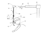
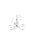
しかし、上記特許文献の方法では、図14に示す様に装着者が頭110を前方に傾けた時、映像表示装置100を吊り下げている紐状体101にかかっている張力Tの作用方向と映像表示装置100の重心Gに作用する重力による荷重Wの方向のズレによる力Fが発生する。更に、張力Tと荷重Wの作用点の違いによるモーメントMも発生する。これらの力FとモーメントMは装着者110の首の回転中心Oに対して作用するため、頭110が押し戻される方向に力を受け、表示装置100が軽い場合と同等な状態を実現することができない。 However, in the method of the above-mentioned patent document, when the wearer tilts the head 110 forward as shown in FIG. 14, the direction of action of the tension T applied to the string-like body 101 that suspends the video display device 100 and A force F is generated due to a shift in the direction of the load W due to gravity acting on the center of gravity G of the image display device 100. Furthermore, a moment M is also generated due to the difference in action point between the tension T and the load W. Since these forces F and moment M act on the center of rotation O of the neck of the wearer 110, they receive a force in the direction in which the head 110 is pushed back, and can realize a state equivalent to the case where the display device 100 is light. Can not.

上記課題に鑑み、頭部搭載型の映像表示装置などの頭部搭載型装置を使用者の頭部に装着するための本発明の懸架式装着装置は以下の手段ないし機構を有することを特徴とする。すなわち、これは、使用者の頭部に頭部搭載型装置を固定する固定手段と、第1の手段と、第2の手段と、第3の手段を有する。第1の手段は、頭部搭載型装置を空間中において任意の方向に傾ける3自由度を得るための3つの独立な(平行ではない)回転軸を頭部搭載型装置のほぼ重心を通って構成する機構である。第2の手段は、前記回転軸の1つを常に鉛直方向にほぼ一致させるための機構である。第3の手段は、頭部搭載型装置の重力による荷重を、釣り合いを保ってキャンセルするために前記第1の手段を上下方向に移動可能に懸架するための機構である。ここにおいて、回転軸は、回転支持軸などとして実際に物理的に存在する軸である場合もあるし、全体の機構の中で仮想的に構成される軸として存在する場合もある。 In view of the above problems, the suspension mounting device of the present invention for mounting a head mounted device such as a head mounted video display device on the user's head has the following means or mechanism. To do. That is, this has a fixing means for fixing the head-mounted device to the user's head, a first means, a second means, and a third means. The first means is to pass three independent (not parallel) rotation axes through the approximate center of gravity of the head-mounted device to obtain three degrees of freedom to tilt the head-mounted device in any direction in space. It is a mechanism to configure. The second means is a mechanism for always causing one of the rotating shafts to substantially coincide with the vertical direction. The third means is a mechanism for suspending the first means movably in the vertical direction in order to cancel the load due to gravity of the head-mounted device in a balanced manner. Here, the rotation axis may be an axis that actually physically exists as a rotation support axis or the like, or may exist as an axis that is virtually configured in the entire mechanism.

また、上記課題に鑑み、本発明の懸架式頭部搭載型映像表示装置は、使用者の眼前から映像を表示する頭部搭載型の映像表示装置本体と、上記の懸架式装着装置を有することを特徴とする。 In view of the above problems, the suspended head-mounted image display device of the present invention includes a main body of a head-mounted image display device that displays an image from the user's eyes, and the above-described suspended mounting device. It is characterized by that.

上述した本発明によれば、映像表示装置などの頭部搭載型装置に作用する張力と重力による荷重方向を常にほぼ一致させることができる。したがって、使用者の頭部に固定した装置を任意の方向に傾ける際、懸架による張力と重力による荷重方向のズレによる力及び作用点のズレによるモーメントの発生が防止ないし低減される。こうして、頭部搭載型装置を装着した装着者に対し重量による荷重がほぼ作用しない様にでき、軽い頭部搭載型装置を装着しているのとほぼ同じ様な状態を実現できる。頭を動かした時も頭部搭載型装置の重量による負荷が殆ど作用せず、頭部搭載型装置が頭の動きにスムーズに追従して頭部搭載型装置が軽い場合と同等な状態を実現できる。 According to the present invention described above, the tension acting on a head-mounted device such as a video display device and the load direction due to gravity can always be made substantially coincident. Therefore, when the device fixed on the user's head is tilted in an arbitrary direction, the generation of moments due to the force due to the tension due to the suspension and the deviation of the load direction due to the gravity and the deviation of the action point can be prevented or reduced. In this way, a load due to weight is hardly applied to a wearer wearing the head-mounted device, and a state almost the same as that of wearing a light head-mounted device can be realized. Even when the head is moved, the load due to the weight of the head-mounted device hardly affects, and the head-mounted device smoothly follows the movement of the head and realizes the same state as when the head-mounted device is light it can.

以下、本発明の実施の形態を明らかにすべく、具体的な実施例を図に沿って説明する。 Hereinafter, specific examples will be described with reference to the drawings in order to clarify the embodiments of the present invention.

<第一の実施例>
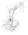
図1は本発明による第一の実施例に係る懸架式頭部搭載型映像表示装置を示す斜視図である。図1において、1は映像表示装置である。この映像表示装置1は、表示部2と装着部3(固定手段)から構成される。
<First embodiment>
FIG. 1 is a perspective view showing a suspended head-mounted image display apparatus according to a first embodiment of the present invention. In FIG. 1, 1 is a video display device. The video display device 1 includes a display unit 2 and a mounting unit 3 (fixing means).

表示部2は、図2に示す様に、映像表示用の液晶パネル等からなる表示パネル30、そのパネル30上に表示した映像を虚像として観察者の眼32に提示するためのプリズムレンズ31を備えている。図2中、一点鎖線Jは表示光学系の光路を示す。また、表示部2は更に、レンズ34とCCD等の撮像素子35からなる撮像カメラ33を有し、表示の中心、すなわち観察者の眼32の視線方向Jと撮像カメラ33の光軸中心K(図中一点鎖線で示す)とを一致させる構成となっている。これにより、観察者は、外界像を自分の眼32で見るが如くカメラ33を通して見ることができる。パネル30上に表示される映像は、撮像素子35からの映像信号をPCなどで処理して構成されるものである。図1に示す部分2aは撮像カメラ33の窓を示している。 As shown in FIG. 2, the display unit 2 includes a display panel 30 composed of a liquid crystal panel for displaying images, and a prism lens 31 for presenting an image displayed on the panel 30 to a viewer's eye 32 as a virtual image. I have. In FIG. 2, an alternate long and short dash line J indicates the optical path of the display optical system. The display unit 2 further includes an imaging camera 33 including a lens 34 and an imaging device 35 such as a CCD. The display center, that is, the line-of-sight direction J of the observer's eye 32 and the optical axis center K ( (Shown by a one-dot chain line in the figure). As a result, the observer can view the external image through the camera 33 as if it were viewed with his / her own eye 32. The video displayed on the panel 30 is configured by processing a video signal from the image sensor 35 with a PC or the like. A portion 2a shown in FIG. 1 shows a window of the imaging camera 33.

装着部3は、表示部2に一体的に設けられた左右方向に伸びたフレーム4、5と、それらの後端部を連結する可撓性のバンド7と、バンド7に一体的に取り付けられた後頭部押え8を有する。フレーム4、5には、バンド7の長さを調整するためのラチェット機構(図示せず)を有するつまみ4a、5aが夫々設けられている。このつまみ4a、5aを矢印H方向に動かすことにより、後頭部押え8を前後に動かすことができる。これにより、表示部2に設けられた前頭部押え6との間で観察者の頭部を前後で挟み、表示部2を、したがって映像表示装置1を頭部に固定する様になっている。 The mounting portion 3 is integrally attached to the band 7 and the frames 4 and 5 that are provided integrally with the display portion 2 and extend in the left-right direction, the flexible band 7 that connects the rear end portions thereof, and the band 7. It has a back head presser 8. The frames 4 and 5 are provided with knobs 4a and 5a having a ratchet mechanism (not shown) for adjusting the length of the band 7, respectively. By moving these knobs 4a, 5a in the direction of arrow H, the occipital region presser 8 can be moved back and forth. Thereby, the observer's head is sandwiched between the front head presser 6 provided in the display unit 2 and the display unit 2 and thus the video display device 1 is fixed to the head. .

表示部2の側面2b、2cには、これらに対して矢印A方向に回転自在に取り付けられた回転支持軸9、10が離間して設けられている。この支持軸9、10の回転軸中心Xは、表示部2と装着部3からなる映像表示装置1の重心Gを通る位置に設けられている。支持軸9、10の端部には更にピン9a、10aが回転自在に設けられ、ピン9a、10aにはワイヤー等の紐状体11が取り付けられている。そして、紐状体11は、その中心付近において、支持部材13に矢印B方向に回転自在に取り付けられているプーリ12により懸架され、表示装置1を支持部材13から吊り下げている。 On the side surfaces 2b and 2c of the display unit 2, there are provided rotation support shafts 9 and 10, which are attached to the side surfaces 2b and 2c so as to be rotatable in the direction of arrow A. The rotation shaft center X of the support shafts 9 and 10 is provided at a position passing through the center of gravity G of the video display device 1 including the display unit 2 and the mounting unit 3. Further, pins 9a and 10a are rotatably provided at end portions of the support shafts 9 and 10, and a string-like body 11 such as a wire is attached to the pins 9a and 10a. The string-like body 11 is suspended near the center by a pulley 12 that is rotatably attached to the support member 13 in the direction of arrow B, and the display device 1 is suspended from the support member 13.

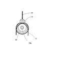
紐状体11は、図3、図4に示す様に、プーリ12に対し少なくとも1重に巻かれた状態で懸架されている。プーリ12の回転軸12aの伸長方向は、X軸に垂直で重心Gを通るY軸に平行になっている。これにより、表示装置1をY軸の回りで回転可能としている。このY軸の回転軸は、全体の機構の中で仮想的に構成される軸として存在するものである。図示の様に、紐状体11をプーリ12に対し2重程度巻くことが、適当な摩擦力を発生させて表示装置1の姿勢をその時々の状態に保持するのに好ましい。 As shown in FIGS. 3 and 4, the string-like body 11 is suspended from the pulley 12 in a state of being wound at least once. The extending direction of the rotating shaft 12a of the pulley 12 is parallel to the Y axis that is perpendicular to the X axis and passes through the center of gravity G. Thus, the display device 1 can be rotated around the Y axis. The rotation axis of the Y axis exists as an axis that is virtually configured in the entire mechanism. As shown in the drawing, it is preferable that the string-like body 11 is wound around the pulley 12 twice in order to generate an appropriate frictional force and maintain the posture of the display device 1 in its state.

支持部材13は、矢印C方向に回転自在にワイヤー等の紐状体14に取り付けられている。ここで、紐状体14が十分長い場合は紐状体の捩れを利用することも可能であり、支持部材13を矢印C方向に回転自在にする回転機構を必ずしも必要とするものではない。 The support member 13 is attached to a string-like body 14 such as a wire so as to be rotatable in the direction of arrow C. Here, when the string-like body 14 is sufficiently long, the twist of the string-like body can be used, and a rotation mechanism that allows the support member 13 to rotate in the direction of arrow C is not necessarily required.

紐状体14は、長さ調整部16に連結されている。この長さ調整部16は図5に示す様に定荷重バネ17を有し、紐状体14はこの定荷重バネ17に連結されている。したがって、映像表示装置1は、定荷重バネ17による紐状体14の巻き取り或いは巻き戻しにより、支持部材13を介して、重量と釣り合いを保ちながら矢印Dで示す上下方向に移動可能に取り付けられている。 The string-like body 14 is connected to the length adjusting unit 16. As shown in FIG. 5, the length adjusting unit 16 has a constant load spring 17, and the string-like body 14 is connected to the constant load spring 17. Therefore, the video display device 1 is attached so as to be movable in the vertical direction indicated by the arrow D while maintaining the weight and balance through the support member 13 by winding or unwinding the string-like body 14 by the constant load spring 17. ing.

長さ調整部16内には、センサー部15が入り口に設けられている。センサー部15では、紐状体14を囲む様にフォトカプラなどのセンサー18が取り付けられ、紐状体14の符号14A、14Bで示す方向或いは図5の紙面に垂直な方向の傾きを検出する様になっている。ここで、映像表示装置1に外力が加わらない状態、すなわち紐状体14が鉛直に伸びている場合は、紐状体14は映像表示装置1の重心Gを通るZ軸と一致している。 In the length adjustment unit 16, a sensor unit 15 is provided at the entrance. In the sensor unit 15, a sensor 18 such as a photocoupler is attached so as to surround the string-like body 14, and the inclination of the string-like body 14 in the direction indicated by reference numerals 14A and 14B or the direction perpendicular to the paper surface of FIG. 5 is detected. It has become. Here, when no external force is applied to the video display device 1, that is, when the string-like body 14 extends vertically, the string-like body 14 coincides with the Z axis passing through the center of gravity G of the video display apparatus 1.

長さ調整部16は、回転アーム21に対し矢印E方向に摺動する摺動アーム20に一体的に取り付けられている。ここには、摺動アーム20を回転アーム21に対し摺動制御するための駆動モータ等を有する長さ調整駆動部22が設けられている。 The length adjusting unit 16 is integrally attached to a sliding arm 20 that slides in the direction of arrow E with respect to the rotating arm 21. Here, a length adjustment drive unit 22 having a drive motor and the like for sliding control of the slide arm 20 with respect to the rotary arm 21 is provided.

また、回転アーム21は、支柱24に設けられた駆動モータ等を有する回転駆動部23により矢印F方向に回転駆動制御される。支柱24等の部材を介して、映像表示装置1に映像信号や、電源等を供給するためのケーブル19が這い回されている。このケーブル19が十分な可撓性を有する場合は、紐状体14をこのケーブル19で兼ねる様にした構成も可能である。 The rotation arm 21 is rotationally driven and controlled in the direction of arrow F by a rotation drive unit 23 having a drive motor or the like provided on the column 24. A cable 19 for supplying a video signal, a power source, and the like to the video display device 1 is wound around through a member such as the support 24. If the cable 19 has sufficient flexibility, a configuration in which the cable-like body 14 also serves as the cable 19 is possible.

上記構成において、映像表示装置1を空間中において任意の方向に傾ける3自由度を得るための3つの独立な回転軸を頭部搭載型装置のほぼ重心を通って構成する第1の手段は、回転支持軸9、10、紐状体11、プーリ12、支持部材13、紐状体14などで構成される。 In the above configuration, the first means for configuring the three independent rotation shafts through the substantially center of gravity of the head-mounted device to obtain three degrees of freedom for tilting the video display device 1 in an arbitrary direction in the space, The rotary support shafts 9 and 10, the string-like body 11, the pulley 12, the support member 13, the string-like body 14 and the like are included.

前記回転軸の1つを常に鉛直方向にほぼ一致させるための第2の手段は、検知手段であるセンサー部15、アーム20、21、長さ調整駆動部22、回転駆動部23などで構成される。頭部搭載型映像表示装置1の重力による荷重を釣り合いを保ってキャンセルするために前記第1の手段を上下方向に移動可能に懸架するための第3の手段は、定荷重バネ17を有する長さ調整部16などで構成される。定荷重バネ17に替えて、トルクモータ、錘等のバランサー装置を使用することもできる。また、前記第1の手段を介して映像表示装置1を懸架して空間中の任意の位置に移動可能とする前記第2の手段の移動手段は、アーム20、21、長さ調整駆動部22、回転駆動部23などで構成される。 The second means for making one of the rotating shafts substantially coincide with the vertical direction at all times includes a sensor unit 15 that is a detecting unit, arms 20, 21, a length adjustment driving unit 22, a rotation driving unit 23, and the like. The The third means for suspending the first means movably in the vertical direction in order to cancel the load due to gravity of the head-mounted image display device 1 in a balanced manner is a length having a constant load spring 17. It is composed of a thickness adjustment unit 16 and the like. Instead of the constant load spring 17, a balancer device such as a torque motor or a weight can be used. Further, the moving means of the second means, which allows the video display device 1 to be suspended and moved to any position in the space via the first means, are the arms 20, 21 and the length adjusting drive unit 22. The rotation drive unit 23 and the like.

また、紐状体14は、映像表示装置1の重心を通るほぼ鉛直方向の回転軸の回りに映像表示装置1を回転自在にするために鉛直方向に懸架されてプーリ12を支持する懸架手段を構成する。 The string-like body 14 is a suspension means that is suspended in the vertical direction and supports the pulley 12 in order to make the video display device 1 rotatable about a substantially vertical rotation axis that passes through the center of gravity of the video display device 1. Constitute.

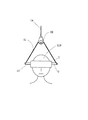
図6、図7は、以上に説明した構成の映像表示装置1を観察者の頭部110に固定した状態を示したものである。図6はその側面から見た図、図7はその正面から見た図である。図6で、装着者が頭110を前に傾けた場合、図8に示す様に、映像表示装置1は装着者の頭110の動きに合わせ、回転支持軸9(10)の働きにより、紐状体11、14に対し矢印Nで示す方向に回転する。このとき頭部110はほぼ首の中心Oを中心に回転するため、表示装置1の重心Gの位置とのズレにより、紐状体11、したがって紐状体14は一点鎖線14aで示す様に傾く。また同時に重心Gの位置が下がる。 6 and 7 show a state in which the video display device 1 having the above-described configuration is fixed to the observer's head 110. FIG. 6 is a view from the side, and FIG. 7 is a view from the front. In FIG. 6, when the wearer tilts the head 110 forward, as shown in FIG. 8, the video display device 1 is linked to the movement of the wearer's head 110 by the rotation support shaft 9 (10). It rotates in the direction indicated by the arrow N with respect to the bodies 11 and 14. At this time, since the head 110 rotates about the center O of the neck, the string-like body 11, and thus the string-like body 14 tilts as shown by the alternate long and short dash line 14a due to the deviation from the position of the center of gravity G of the display device 1. . At the same time, the center of gravity G is lowered.

重心Gの下方への移動に対しては、定荷重バネ17による巻き戻しにより紐状体14が矢印L方向に移動する。紐状体14の傾きに関しては、センサー部15に内蔵するセンサー18により検出され、その傾きをキャンセルする方向に長さ調整駆動部22がアーム20を矢印M方向に移動させる。すなわち、センサー18の検出結果に基づいて、常に紐状体14は鉛直になる様に制御されるので、表示装置1の重量による荷重方向と紐状体14の張力方向は一致する。こうして、張力Tと重量の荷重方向Wとの違いによる力F1は発生しない。 For the downward movement of the center of gravity G, the string-like body 14 moves in the direction of the arrow L by rewinding by the constant load spring 17. The inclination of the string-like body 14 is detected by the sensor 18 incorporated in the sensor unit 15, and the length adjustment drive unit 22 moves the arm 20 in the direction of arrow M in a direction to cancel the inclination. That is, since the string-like body 14 is always controlled to be vertical based on the detection result of the sensor 18, the load direction due to the weight of the display device 1 matches the tension direction of the string-like body 14. Thus, the force F1 due to the difference between the tension T and the weight load direction W is not generated.

また、表示装置1の重心Gの位置と回転軸位置が一致しているので、作用点のズレによるモーメントも生じない。したがって、装着者は映像表示装置1からの力を殆ど受けない。ただし、表示装置1を動かす時に発生する回転部分等での摩擦力や装置の慣性力は作用する。しかし、摩擦力については、各回転部や摺動部にベアリング等の軸受けを使用することで実用上無視できる位に小さくでき、慣性力については急激な動きを必要とする様な目的でなければ実用上無視できる。 Further, since the position of the center of gravity G of the display device 1 and the position of the rotation axis coincide with each other, no moment is generated due to the displacement of the action point. Therefore, the wearer receives almost no force from the video display device 1. However, the frictional force at the rotating part or the like generated when the display device 1 is moved or the inertial force of the device acts. However, the frictional force can be reduced to a practically negligible value by using bearings such as bearings for each rotating part and sliding part, and the inertial force is not intended to require rapid movement. It can be ignored in practice.

この点、映像表示装置をアームで支持する様にしたもの(特開平8−125948号公報参照)と比較して、本実施例は優れる。このアームで支持する装置の場合は、映像表示部を支持するためにアームの連結部に生じている摩擦等の負荷が、頭を動かす時に抵抗となり、軽い映像表示装置を装着した時と同等な状態を実現できない。この摩擦等の負荷は、映像表示部を支持するために不可欠なもので一定程度の大きさを確保する必要がある。したがって、本実施例の様に摩擦力などを実用上無視できる位に小さくできるものと比べて、映像表示装置を装着した時の負荷が大きくなる。 In this respect, the present embodiment is superior to a video display device supported by an arm (see Japanese Patent Laid-Open No. 8-125948). In the case of a device supported by this arm, a load such as friction generated in the connecting portion of the arm to support the image display unit becomes resistance when moving the head, which is equivalent to when a light image display device is mounted. The state cannot be realized. The load such as friction is indispensable for supporting the video display unit, and needs to secure a certain level. Therefore, the load when the video display device is attached becomes larger than that in which the frictional force can be reduced to a practically negligible level as in this embodiment.

図7に示す状態から、図9の様に左右方向に頭110を傾けた場合、映像表示装置1は頭110の傾きに合わせてプーリ12を矢印P方向に回転させ、紐状体11の懸架位置を移動させる。これにより映像表示装置1は、ほぼ映像表示装置1の重心Gを中心に矢印Qに示す様に回転移動する。この移動では、プーリ12の回転と表示装置1に取り付けた回転支持軸9、10の端部のピン9a、10aの回転で発生する摩擦負荷以外に負荷は作用しないので、移動はスムーズに行われる。 From the state shown in FIG. 7, when the head 110 is tilted in the left-right direction as shown in FIG. 9, the video display device 1 rotates the pulley 12 in the direction of arrow P in accordance with the tilt of the head 110, Move position. As a result, the video display device 1 rotates and moves as indicated by an arrow Q about the center of gravity G of the video display device 1. In this movement, no load is applied other than the friction load generated by the rotation of the pulley 12 and the rotation of the pins 9a and 10a at the ends of the rotation support shafts 9 and 10 attached to the display device 1, so that the movement is performed smoothly. .

このとき、首の中心Oと表示装置1の重心Gの位置の間のズレ、或いは装着者の横方向への移動により紐状体14が一点鎖線14aで示す様に傾く。しかしながら、この傾きをセンサー18が検出し、回転アーム21を支柱24に対し矢印Rで示す方向に回転させて、紐状体14の鉛直方向が表示装置1の重心Gを通る様に制御される。したがって、映像表示装置1は図9に示す様に傾いた状態を保持することになり、装着者に対して殆ど力は作用しない。 At this time, the string-like body 14 is inclined as indicated by a one-dot chain line 14a due to a shift between the center O of the neck and the position of the center of gravity G of the display device 1 or a movement in the lateral direction of the wearer. However, this inclination is detected by the sensor 18, and the rotating arm 21 is rotated in the direction indicated by the arrow R with respect to the support column 24 so that the vertical direction of the string-like body 14 passes through the center of gravity G of the display device 1. . Accordingly, the video display device 1 maintains a tilted state as shown in FIG. 9, and almost no force acts on the wearer.

なお、頭110をZ軸に対し左右方向に回転させた場合は、表示装置1の重心Gを通る方向に懸架された紐状体14に対して表示装置1は回転自在に取り付けられているので、任意の方向に向いた状態を保持することが可能である。 When the head 110 is rotated in the left-right direction with respect to the Z axis, the display device 1 is rotatably attached to the string-like body 14 suspended in the direction passing through the center of gravity G of the display device 1. It is possible to hold a state facing in any direction.

以上述べた如く、映像表示装置1は装着者の頭110の移動に合わせて、3次元的に空間内を移動し、紐状体14などで支えられて任意の方向に傾いた状態を保持する。したがって、装着者に対しては映像表示装置1の重量による負荷が殆ど作用しない。 As described above, the video display device 1 moves three-dimensionally in the space in accordance with the movement of the wearer's head 110, and is supported by the string-like body 14 or the like and maintains a state inclined in an arbitrary direction. . Therefore, the load due to the weight of the video display device 1 hardly acts on the wearer.

更に、映像表示装置1に離間して設けられた回転支持軸9、10に対して上記の如く紐状体11などを設けて回転支持軸9、10に直交する仮想的な回転軸を構成し、これらの軸の交点を重心位置に一致させて映像表示装置1の回転軸を形成している。そのために、表示部2を囲う様に入れ子状にフレームを設けて直交する2つの回転軸を形成する必要がなく、回転支持軸9、10に直交する回転軸を構成する機構を表示部2の前面からずらすことができる。こうして、表示部2の前面を遮ることなくシンプル且つ軽量に装置を構成することができる。 Furthermore, the virtual support shaft perpendicular to the rotation support shafts 9 and 10 is configured by providing the string-like bodies 11 and the like as described above with respect to the rotation support shafts 9 and 10 provided apart from the video display device 1. The rotation axis of the video display device 1 is formed by matching the intersection of these axes with the position of the center of gravity. Therefore, it is not necessary to provide a frame that is nested so as to surround the display unit 2 to form two orthogonal rotation axes, and a mechanism that constitutes the rotation axis orthogonal to the rotation support shafts 9 and 10 is provided in the display unit 2. Can be shifted from the front. Thus, the apparatus can be configured simply and lightly without blocking the front surface of the display unit 2.

上記説明では、映像表示装置1の頭部110への固定方法として、バンドを用いたゴーグルタイプとしたが、映像表示部2を固定できればこれに限定されるものではない。眼鏡の弦の様な固定方法でもよい。 In the above description, the method of fixing the video display device 1 to the head 110 is a goggle type using a band. However, the method is not limited to this as long as the video display unit 2 can be fixed. A fixing method like a string of glasses may be used.

また、装置の固定に支柱24を使用したが、天井に回転駆動部23などを固定する様にしてもよい。さらに、上記の説明では、映像表示装置1の重心Gと装着者の首の回転中心Oとのズレに対して、紐状体14の上下方向の移動、アーム20の摺動及びアーム21の回転による位置調整を行ったが、これは、装着者が動いたりした場合に対しても対応できる。すなわち、装着者は、映像表示装置1の重量負荷を殆ど感じることなく、任意の方向に映像表示装置1を傾けながら空間内を移動できる。 Further, although the column 24 is used for fixing the apparatus, the rotation driving unit 23 and the like may be fixed to the ceiling. Further, in the above description, the vertical movement of the string-like body 14, the sliding of the arm 20, and the rotation of the arm 21 with respect to the deviation between the center of gravity G of the video display device 1 and the rotation center O of the neck of the wearer The position adjustment according to the above has been performed, but this can also be dealt with when the wearer moves. That is, the wearer can move in the space while tilting the video display device 1 in an arbitrary direction without almost feeling the weight load of the video display device 1.

<第二の実施例>
次に、本発明の第二の実施例を説明する。図10乃至図13は第二の実施例を示す。第二の実施例は、首の回転中心Oに映像表示装置1の重心Gをほぼ一致させ、そこを通る回転軸を中心に映像表示装置1が回転する様にしたものである。その他の点は第一の実施例と同様である。
<Second Example>
Next, a second embodiment of the present invention will be described. 10 to 13 show a second embodiment. In the second embodiment, the center of gravity G of the video display device 1 is substantially coincident with the rotation center O of the neck, and the video display device 1 is rotated around the rotation axis passing therethrough. Other points are the same as in the first embodiment.

図10乃至図13において、54、55は表示部2の左右の側面部より夫々下方向に伸びたアームである。アーム54、55は、表示部2の左右の側面部に対して所定の角度で固定的に取り付けられている。そして、アーム54、55の中間付近、装着者の首の回転中心Oにほぼ一致する位置に、図示する様に、アーム54、55に対し回転自在に回転支持軸50、51が設けられている。この支持軸50、51の先端部には、第一の実施例と同様に、回転自在にピン50a、51aが取り付けられ、このピン50a、51aに紐状体11が取り付けられている。また、アーム54、55に取り付けられた回転支持軸50、51が表示装置1の重心Gのところに来る様に、アーム54、55の端におもり52、53が夫々取り付けられている。 10 to 13, reference numerals 54 and 55 denote arms extending downward from the left and right side portions of the display unit 2, respectively. The arms 54 and 55 are fixedly attached to the left and right side surfaces of the display unit 2 at a predetermined angle. As shown in the drawing, rotation support shafts 50 and 51 are provided so as to be rotatable about the middle of the arms 54 and 55, at a position substantially coincident with the center of rotation O of the wearer's neck. . Similar to the first embodiment, pins 50a and 51a are rotatably attached to the tip portions of the support shafts 50 and 51, and the string-like body 11 is attached to the pins 50a and 51a. Further, weights 52 and 53 are respectively attached to the ends of the arms 54 and 55 so that the rotation support shafts 50 and 51 attached to the arms 54 and 55 come to the center of gravity G of the display device 1.

装着者が図12に示す様に左右方向に頭110を傾ける場合、或いは図13に示す様に前方向に傾ける場合、首の回転中心Oに重心Gの位置が一致し、そこを通る回転軸を回転中心として表示装置1を傾けるので、紐状体14を水平面内で移動させる必要がない。すなわち、第二の実施例では、座って作業する等、頭110を傾けるだけの動きであれば、第一の実施例に示した様な紐状体14を水平面内で移動するための機構が必要でなくなり、装置を簡略化できる。勿論、装着者が水平面内で移動する場合に適用する装置では、第一の実施例に示した様な紐状体14を水平面内で移動するための機構を設ければよい。 When the wearer tilts the head 110 in the left-right direction as shown in FIG. 12 or tilts forward as shown in FIG. 13, the position of the center of gravity G coincides with the rotation center O of the neck, and the rotation axis passes there Since the display device 1 is tilted about the rotation center, there is no need to move the string-like body 14 in the horizontal plane. That is, in the second embodiment, a mechanism for moving the string-like body 14 in the horizontal plane as shown in the first embodiment as long as the head 110 is tilted, such as sitting and working. It is not necessary and the device can be simplified. Of course, in an apparatus applied when the wearer moves in a horizontal plane, a mechanism for moving the string-like body 14 in the horizontal plane as shown in the first embodiment may be provided.

第二の実施例の構成においては、上記の第1の手段は、回転支持軸50、51、紐状体11、プーリ12、支持部材13、紐状体14などで構成される。上記の第2の手段は、省くことができるが、第一の実施例と同様、検知手段であるセンサー部15、アーム20、21、長さ調整駆動部22、回転駆動部24などで第二手段を構成しても良い。さらに上記第三の手段は、第一の実施例と同様に長さ調整部16から構成される。また、映像表示装置1の重心を使用者の首の回転中心にほぼ一致させるための第4の手段は、アーム54、55、おもり52、53などで構成される。 In the configuration of the second embodiment, the first means includes the rotation support shafts 50 and 51, the string-like body 11, the pulley 12, the support member 13, the string-like body 14, and the like. Although the second means can be omitted, as in the first embodiment, the sensor unit 15, which is the detection means, the arms 20, 21, the length adjustment drive unit 22, the rotation drive unit 24, etc. Means may be configured. Further, the third means includes the length adjusting unit 16 as in the first embodiment. The fourth means for making the center of gravity of the video display device 1 substantially coincide with the center of rotation of the user's neck includes arms 54 and 55, weights 52 and 53, and the like.

ところで、上記実施例では、頭部搭載型の映像表示装置について説明したが、本発明の懸架式装着装置ないし装着方法は、これ以外の頭部搭載型の装置のどの様なものにも適用することができる。 In the above embodiment, the head-mounted image display device has been described. However, the suspension mounting device or mounting method of the present invention is applicable to any other head-mounted device. be able to.

図1は本発明による第一の実施例を示す斜視図。FIG. 1 is a perspective view showing a first embodiment according to the present invention. 図2は表示部の概略を示す説明図。FIG. 2 is an explanatory diagram showing an outline of the display unit. 図3は紐状体11をプーリに懸架した状態を示す断面図。FIG. 3 is a cross-sectional view showing a state in which the string-like body 11 is suspended from a pulley. 図4は紐状体11をプ−リに懸架した状態を示す側面図。FIG. 4 is a side view showing a state in which the string-like body 11 is suspended from the pulley. 図5は紐状体14の長さ調整部の説明図。FIG. 5 is an explanatory diagram of the length adjusting unit of the string-like body 14. 図6は映像表示装置を装着した状態を示す側面図。FIG. 6 is a side view showing a state in which the video display device is mounted. 図7は映像表示装置を装着した状態を示す正面図。FIG. 7 is a front view showing a state in which the video display device is mounted. 図8は映像表示装置を前方向に傾けた状態を示す図。FIG. 8 is a diagram showing a state in which the video display device is tilted forward. 図9は映像表示装置を左右方向に傾けた状態を示す図。FIG. 9 is a diagram showing a state in which the video display device is tilted in the left-right direction. 図10は本発明による第二の実施例を示す正面図。FIG. 10 is a front view showing a second embodiment according to the present invention. 図11は第二の実施例を示す側面図。FIG. 11 is a side view showing the second embodiment. 図12は第二の実施例において映像表示装置を左右方向に傾けた状態を示す図。FIG. 12 is a diagram showing a state in which the video display device is tilted in the left-right direction in the second embodiment. 図13は第二の実施例において映像表示装置を前方向に傾けた状態を示す図。FIG. 13 is a diagram showing a state in which the video display device is tilted forward in the second embodiment. 図14は従来例を説明する図。FIG. 14 is a diagram for explaining a conventional example.

符号の説明Explanation of symbols

1 頭部搭載型装置(頭部搭載型映像表示装置)
2 表示部
3 装着部
9、10、50、51 回転支持軸
11、14 紐状体
12 プーリ
13 プーリ支持部材
15 センサー部
16 長さ調整部
20 摺動アーム
21 回転アーム
22 長さ調整駆動部
23 回転駆動部
52、53 おもり
54、55 アーム
1 Head-mounted device (head-mounted image display device)
2 Display section
3 Mounting part
9, 10, 50, 51 Rotating support shaft
11, 14 String
12 pulley
13 Pulley support member
15 Sensor section
16 Length adjustment section
20 Sliding arm
21 Rotating arm
22 Length adjustment drive
23 Rotation drive
52, 53 Weight
54, 55 arms

Claims (8)

頭部搭載型装置を使用者の頭部に装着するための懸架式装着装置であって、頭部に頭部搭載型装置を固定する固定手段と、頭部搭載型装置を空間中において任意の方向に傾ける3自由度を得るための3つの独立な回転軸を頭部搭載型装置重心を通って構成する第1の手段と、前記回転軸の1つを常に鉛直方向一致させるための第2の手段と、頭部搭載型装置の重力による荷重を、釣り合いを保ってキャンセルするために前記第1の手段を上下方向に移動可能に懸架するための第3の手段を有することを特徴とする懸架式装着装置。 A suspension-type mounting device for mounting a head-mounted device on a user's head, the fixing means for fixing the head-mounted device to the head, and the head-mounted device in any space a first means constituting the three independent rotation axis to obtain three degrees of freedom to tilt in the direction through the center of gravity of the head mount apparatus, for matching one of the rotary shaft always in a vertical direction It has second means and third means for suspending the first means movably in the vertical direction in order to cancel the load due to gravity of the head-mounted device in a balanced manner. A suspension mounting device. 前記第1の手段は、頭部搭載型装置の重心を通水平方向の回転軸の回りに頭部搭載型装置を回転自在にするために頭部搭載型装置を挟んで離間して設けられた2つの回転支持軸と、当該水平方向の回転軸と直角方向の回転軸の回りに頭部搭載型装置を回転自在にするために前記2つの回転支持軸間を結ぶとともにその間で回転自在なプーリに懸架されて三角形状に伸びた紐状体と、頭部搭載型装置の重心を通鉛直方向の回転軸の回りに頭部搭載型装置を回転自在にするために鉛直方向に懸架されて該プーリを支持する懸架手段を含むことを特徴とする請求項1記載の懸架式装着装置。 It said first means, spaced apart across the head mount device to the rotatable head mount device about a horizontal direction of the rotational axis center of gravity Ru through the head-mounted device two rotation support shaft which is, during with connecting between the two rotation support shaft to freely rotate the head mount device about the axis of rotation of the rotary shaft at right angles with the direction of the direction of the horizontal in is suspended rotatable pulley and cord-like body extending in a triangular shape, vertical to the rotatable head-mounted device about a passing Ru vertical rotation axis center of gravity of the head-mounted device 2. The suspension mounting apparatus according to claim 1, further comprising suspension means that is suspended in the direction of and supports the pulley. 前記離間して設けられた2つの回転支持軸間を結ぶ紐状体は、前記プーリに対し少なくとも1重に巻かれて取り付けられていることを特徴とする請求項2記載の懸架式装着装置。 3. The suspension mounting device according to claim 2, wherein the string-like body connecting the two rotation support shafts provided apart from each other is attached to the pulley by being wound at least once. . 前記第2の手段は、第1の手段を介して頭部搭載型装置を懸架して空間中の任意の位置に移動可能とする移動手段を含むことを特徴とする請求項1乃至3のいずれかに記載の懸架式装着装置。 4. The method according to claim 1, wherein the second means includes moving means for suspending the head-mounted device via the first means so as to be movable to any position in the space. The suspension mounting device according to claim 1. 前記懸架手段は紐状体であり、前記第2の手段は、該紐状体の傾きを検知する検知手段と、該検知手段の検出結果に基づいて、該紐状体が常に鉛直になる様に、紐状体を鉛直方向垂直な水平面内において移動制御する移動手段を含むことを特徴とする請求項2乃至4のいずれかに記載の懸架式装着装置。 The suspension means is a string-like body, and the second means is a detection means for detecting the inclination of the string-like body, and the string-like body is always vertical based on the detection result of the detection means. , the suspension type mounting device according to any one of claims 2 to 4, characterized in that it comprises a moving means for controlling movement in the string-like body in the vertical direction perpendicular to a horizontal plane. 頭部搭載型装置の重心を、頭部搭載型装置を頭部に固定した使用者の首の回転中心に致させるための第4の手段を更に有することを特徴とする請求項1乃至5のいずれかに記載の懸架式装着装置。 The center of gravity of the head mount apparatus, according to claim 1 or 5 the head-mounted device, characterized by further comprising a fourth means for causing one Itasa the center of rotation of the user's neck fixed to the head The suspension mounting apparatus according to any one of the above. 前記頭部搭載型装置は、頭部搭載型の映像表示装置であることを特徴とする請求項1乃至6のいずれかに記載の懸架式装着装置。 7. The suspension mounting device according to claim 1, wherein the head-mounted device is a head-mounted image display device. 使用者の眼前から映像を表示する頭部搭載型の映像表示装置本体と、請求項7記載の懸架式装着装置を有することを特徴とする懸架式頭部搭載型映像表示装置。 A body of the head-mounted image display device that displays an image from the front of the user, suspension type head mount type image display apparatus characterized by having a suspension type mounting apparatus according to claim 7 wherein.
JP2005353115A 2005-12-07 2005-12-07 Suspension-type mounting device and suspension-type head-mounted image display device using the same Expired - Fee Related JP4557877B2 (en)

Priority Applications (1)

Application Number Priority Date Filing Date Title
JP2005353115A JP4557877B2 (en) 2005-12-07 2005-12-07 Suspension-type mounting device and suspension-type head-mounted image display device using the same

Applications Claiming Priority (1)

Application Number Priority Date Filing Date Title
JP2005353115A JP4557877B2 (en) 2005-12-07 2005-12-07 Suspension-type mounting device and suspension-type head-mounted image display device using the same

Publications (3)

Publication Number Publication Date
JP2007158894A JP2007158894A (en) 2007-06-21
JP2007158894A5 JP2007158894A5 (en) 2009-01-22
JP4557877B2 true JP4557877B2 (en) 2010-10-06

Family

ID=38242646

Family Applications (1)

Application Number Title Priority Date Filing Date
JP2005353115A Expired - Fee Related JP4557877B2 (en) 2005-12-07 2005-12-07 Suspension-type mounting device and suspension-type head-mounted image display device using the same

Country Status (1)

Country Link
JP (1) JP4557877B2 (en)

Families Citing this family (2)

* Cited by examiner, † Cited by third party
Publication number Priority date Publication date Assignee Title
WO2012157212A1 (en) * 2011-05-16 2012-11-22 シャープ株式会社 Three-dimensional image display device, and three-dimensional image display method
CN111720711B (en) * 2020-05-18 2022-03-15 深圳创维-Rgb电子有限公司 Television hanging rack and television

Citations (8)

* Cited by examiner, † Cited by third party
Publication number Priority date Publication date Assignee Title
JPH05293791A (en) * 1992-04-21 1993-11-09 Nippon Steel Corp Support method for solid image presenting device
JPH06195440A (en) * 1992-12-24 1994-07-15 Olympus Optical Co Ltd Head follow-up type display device
JPH07318852A (en) * 1994-05-26 1995-12-08 Nippon Steel Corp Weight compensating device for stereoscopic video display device
JPH0884328A (en) * 1994-09-13 1996-03-26 Nippon Telegr & Teleph Corp <Ntt> Tele-existence type video telephone system
JPH08125948A (en) * 1994-10-28 1996-05-17 Nippon Telegr & Teleph Corp <Ntt> Suction mounting type head mounted display
JPH09307834A (en) * 1996-05-16 1997-11-28 Olympus Optical Co Ltd Personal image display device
JP2005169063A (en) * 2003-11-21 2005-06-30 Takechika Nishi Image display device and simulation device
JP2005244919A (en) * 2004-01-28 2005-09-08 Takechika Nishi Image display device and image display system

Patent Citations (8)

* Cited by examiner, † Cited by third party
Publication number Priority date Publication date Assignee Title
JPH05293791A (en) * 1992-04-21 1993-11-09 Nippon Steel Corp Support method for solid image presenting device
JPH06195440A (en) * 1992-12-24 1994-07-15 Olympus Optical Co Ltd Head follow-up type display device
JPH07318852A (en) * 1994-05-26 1995-12-08 Nippon Steel Corp Weight compensating device for stereoscopic video display device
JPH0884328A (en) * 1994-09-13 1996-03-26 Nippon Telegr & Teleph Corp <Ntt> Tele-existence type video telephone system
JPH08125948A (en) * 1994-10-28 1996-05-17 Nippon Telegr & Teleph Corp <Ntt> Suction mounting type head mounted display
JPH09307834A (en) * 1996-05-16 1997-11-28 Olympus Optical Co Ltd Personal image display device
JP2005169063A (en) * 2003-11-21 2005-06-30 Takechika Nishi Image display device and simulation device
JP2005244919A (en) * 2004-01-28 2005-09-08 Takechika Nishi Image display device and image display system

Also Published As

Publication number Publication date
JP2007158894A (en) 2007-06-21

Similar Documents

Publication Publication Date Title
EP3360001B1 (en) Head mount display device
JP6033866B2 (en) Wearable device having input / output structure
JP5023755B2 (en) Image display device
EP1393117B1 (en) Head mounted display device
EP3356877A1 (en) Eye gaze responsive virtual reality headset
JP6279881B2 (en) Virtual image display device
EP1524540A1 (en) Image observation apparatus
JP4557877B2 (en) Suspension-type mounting device and suspension-type head-mounted image display device using the same
JP2008022236A (en) Head mount display
EP1731959A1 (en) Stereoscopic two-dimensional image display unit
JPH10293544A (en) Head-mount type video display device
US20200233219A1 (en) Reality viewer
JP2009065440A (en) Head-mounted display
JP2007014394A (en) Eyesight restoration training device
JP7455596B2 (en) image display device
JPH07225351A (en) On head mounting video display device
JP6780562B2 (en) Head mounted display
JP6613646B2 (en) Image display device
JP2008022238A (en) Head mount display
US20220326730A1 (en) Head-mounted image display apparatus
JP4336611B2 (en) Information presenting apparatus and information presenting program
US20230004010A1 (en) Wearable display device
JP2010256548A (en) Glasses
JPH09266554A (en) Display device
JPH07191277A (en) Binocular head mounted type video display device

Legal Events

Date Code Title Description
A521 Written amendment

Free format text: JAPANESE INTERMEDIATE CODE: A523

Effective date: 20081202

A621 Written request for application examination

Free format text: JAPANESE INTERMEDIATE CODE: A621

Effective date: 20081202

TRDD Decision of grant or rejection written
A01 Written decision to grant a patent or to grant a registration (utility model)

Free format text: JAPANESE INTERMEDIATE CODE: A01

Effective date: 20100714

A01 Written decision to grant a patent or to grant a registration (utility model)

Free format text: JAPANESE INTERMEDIATE CODE: A01

A61 First payment of annual fees (during grant procedure)

Free format text: JAPANESE INTERMEDIATE CODE: A61

Effective date: 20100720

R150 Certificate of patent or registration of utility model

Free format text: JAPANESE INTERMEDIATE CODE: R150

FPAY Renewal fee payment (event date is renewal date of database)

Free format text: PAYMENT UNTIL: 20130730

Year of fee payment: 3

LAPS Cancellation because of no payment of annual fees