JP4553524B2 - Liquid application method - Google Patents
Liquid application method Download PDFInfo
- Publication number
- JP4553524B2 JP4553524B2 JP2001232832A JP2001232832A JP4553524B2 JP 4553524 B2 JP4553524 B2 JP 4553524B2 JP 2001232832 A JP2001232832 A JP 2001232832A JP 2001232832 A JP2001232832 A JP 2001232832A JP 4553524 B2 JP4553524 B2 JP 4553524B2
- Authority
- JP
- Japan
- Prior art keywords
- liquid
- coating
- application
- cloth
- nozzle
- Prior art date
- Legal status (The legal status is an assumption and is not a legal conclusion. Google has not performed a legal analysis and makes no representation as to the accuracy of the status listed.)
- Expired - Lifetime
Links
- SSOKTUYAEOXEPO-UHFFFAOYSA-N CCCC1(C)CCCCC1 Chemical compound CCCC1(C)CCCCC1 SSOKTUYAEOXEPO-UHFFFAOYSA-N 0.000 description 1
Images


Landscapes
- Coating Apparatus (AREA)
- Apparatus For Disinfection Or Sterilisation (AREA)
- Application Of Or Painting With Fluid Materials (AREA)
Description
【0001】
【発明の属する技術分野】
本発明は、床に消毒液やワックス等の液体を隈なく且つ均一に塗布するための液体の塗布方法に関するものであり、詳細には、滴下ノズルを走査させて走行する液体塗布走行装置とその液体塗布走行装置を使用した際の主に初期動作における液体の塗布方法に関する。
【0002】
【従来の技術】
従来より、床面に対してワックス等の液体を塗布する各種の走行装置が知られているが、一般に、これらの液体を床面に対して塗布する場合には、走行に伴いその作業領域で、広く均一に塗布することが望まれる。例えば、特開平成9年第299857号「走行式ワックス塗布乾燥装置」においては、回動軸に垂設され、先方が左右に振り動かされるワックス注出管を備え、台車の走行に伴ってワックス注出管の先方が左右に振り動かされて、その先端からワックスが広く床面にジグザグ状に供給される構成のワックス供給塗布装置が開示されている。
【0003】
上記の装置によれば、このように構成したワックス注出供給装置によって、容易にワックス液がジグザグに床面へ広く供給されるとされている。
【0004】
【発明が解決しようとする課題】
ところが、上記の如く揺動手段による装置は、装置全体が嵩高となり、高さ方向に制限がある狭い領域での作業が困難であった。また、現状においては、ワックス、消毒の塗布液の塗布作業は、手作業で行われることが多いが、均一な塗布が困難であり、液体の使用量が増えて清掃コストが高くつき、より機能性に優れた液体塗布装置が望まれている。
【0005】
本発明者は、これらの現状と背景を鑑みて、先に、自走する移動台車に取り付けられた液体塗布装置として、左右に走査する1個のノズルから連続的に床に滴下される液体を1枚の布で塗り延ばす方式を採用した装置を開示した。(技術情報誌「HWT(Human With Technology)」1997年9月号記載『ポータブルな自律移動ロボットロボサニタン』)この自律移動ロボットは、図31及び図32に図示の如く、車輪101aなどから成る走行手段と、滴下ノズル103の走査手段とを備え、この滴下ノズル103を走査させながら走行することにより、床面に消毒液やワックスなどの液体を塗布する液体塗布走行装置である。この装置は、走行手段を有する本体の後方に連結されると共に、作業領域の幅方向に移動可能に支持された作業ユニット102を有する。作業ユニット102の端部に設けられた液体塗延手段は、床面に向けて垂下した塗布用布104が設けられている。
【0006】
ところが、この装置のように、床に滴下された液体を布で塗り延ばす方式に於いては、床に塗布する液体の量(塗布膜の厚さ)を均一にするため、予め布に液体を染み込ませておかなければならない。何故ならば、布が乾いた状態で作業を始めると、初めのうちは床に滴下された液体の多くが布に吸収されてしまい、塗布量(塗布膜厚)が少なくなってしまうからであり、また、あらかじめ布の全幅に液体を染み込ませておくことにより、液体が布の端まで浸透しやすくなり、作業幅方向にも均一な塗布が行えるようになるからである。
【0007】
そこで、上記の装置においては、作業領域の幅(布の幅)とノズルの走査の範囲をできる限り近い値とすることにより、布にできるだけ万遍なく液体を染み込ませるようにしていたが、ノズルの走査範囲が布の幅に極めて近い値となるため、布の幅を越えて液体が飛散することがあり、塗布品質を低下させるという不都合があった。
【0008】
また、上記の装置においては、ノズルに液体を供給するチューブを、ノズルの左右移動に対応させるため、釣り竿と釣り糸の如く、ポンプの排出口から、棒バネによって一旦上方に吊り上げられた後、下方に垂らされてノズルに接続させたり、自動編み機の毛糸の引き回しによく似た構成を採用していたため、チューブの配置のみが装置の中で高くなっていて、机やベッドの下などの上限のある領域では、作業する場合に装置が引っかかる心配があり、また見栄えも良くなかった。これは、先に引用した特開平成9年第299857号等も同様である。
【0009】
【本発明が解決しようとする課題】
本発明の液体塗布方法は、これらの課題を解消すべく、床面への液体の塗布にあたって、液体塗延手段である布によって決定される作業領域の外側への液体の飛散や流動による拡散を防止して、塗布品質の向上を実現し、また、装置の高さを低くして、机やベッドの下などでも安全に作業できるようにすることを目的とする。
【0015】
【課題を解決するための手段】
本発明の液体塗布方法は、滴下ノズルで第一の塗布範囲として所定の幅に液体を滴下する工程と、第一の塗布範囲の幅方向の一方の端部を残留させた状態で前記液体塗延手段を通過させて該液体塗延手段の一部に液体を含浸させると共に第一の残留部を形成する工程と、滴下ノズルで第一の残留部の近傍に第2の塗布範囲として所定の幅に液体を滴下する工程と、第2の塗布範囲の幅方向の他方の端部を残留させた状態で且つ前記第一の塗布範囲の残留部を網羅して液体塗延手段を通過させることで該液体塗延手段の全体に液体を含浸させる工程と、第2の塗布範囲の残留部に液体塗延手段を通過させて拭き取る工程から成る。
【0016】
本発明は、前記の方法により、塗布作業開始前には、一旦ノズルを走査して液体を滴下した後、作業ユニットを幅方向に移動させ、更に、本体の前進後退とを組み合わせることで、塗布作業の前段階で、あらかじめ液体塗延手段である布に万遍なく液体を染み込ませることができる。
【0017】
【発明の実施の形態】
以下、本発明の液体塗布走行装置を実施例の図面に基づき説明する。
【0018】
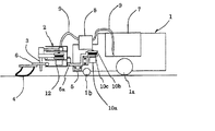
図1は、本発明の液体塗布走行装置の側面概要図であり、図2は、本発明の液体塗布走行装置の平面概要図である。図1に図示の如く、本体1の下部には、走行手段である自在キャスタ1bを含む複数の車輪1aが設けられている。この走行手段は、詳細には、例えば、図示しない走行エンコーダの出力に基づき、回転方向と回転速度が制御され、前進、もしくは後退と、カーブ走行、旋回動作を行う、自走手段を採用することができる。この場合、さらに走行距離を計算し、ジャイロセンサーの出力に基づき、ロボットの方向を算出して、ロボットの位置を計算するとともに、停止位置、及び、方向の制御を行う。また、これらは、公知のコントローラにより設定され、遠隔制御される。
【0019】
図1及び図2に図示の如く、液体塗布走行装置の本体1の後方には、作業ユニット2が、スライドレール5とこのスライドレール5上に移動可能に取り付けられた支持部材5aにより作業領域の幅方向に移動可能に支持され、この作業ユニット2の端部には液体塗延手段である布4が床面に向けて垂設されている。この作業ユニット2は、車輪1aにより走行する本体1に対し着脱可能に連結されている。
【0020】
また、本体1の上方には、ワックス等の塗布用液体を貯留するタンク7が搭載され、このタンク7内からはチューブ9が外側に導出されると共に、この実施例では、本体1の後方側に固定されたポンプ8を経由して作業ユニット2上で、後述する手段により移動可能に支持された滴下ノズル3に接続されている。
【0021】
前記作業ユニット2は、2つのプーリ10b.10bの間で掛け渡されたタイミングベルト10c上に固定されると共にスライドレール5上で移動可能に支持された支持部材5aの先端部に、その側部が固定されており、一方のプーリ10bには作業ユニット移動用モータ10aの軸が設けられていて、図示しない制御部によってモータ10aを制御することにより、本体1の左右に移動することができる。前記作業ユニットの移動用モータ10aには、エンコーダが内蔵されており、回転数に比例したパルス信号を制御部へ出力する。
【0022】
また、作業ユニット2の移動用である前記スライドレール5の両端近傍には、近接センサ13が配置されている。この近接センサ13は、金属の接近を検知するものであり、スライドレール5上を移動する支持部材5aが、スライドレール5の両端近くに達したことを検知し制御部へ出力する。これにより、制御部は、作業ユニットの移動用モータ10aのエンコーダー出力と、近接センサー13の出力を用いて、作業ユニット2を移動範囲内の任意の位置へ移動制御する。
【0023】
尚、前記作業ユニット2のスライド移動用のスライドレール5は、剛性の強度の高いレールなどを用い、縦、横2本用いることにより作業ユニット2の垂れ下がりを防止することが好ましい。
【0024】
一方、図2及び図3乃至図5に図示の通り、滴下ノズル3は、ノズルホルダ14aの縦方向に形成された支持孔に挿入され、このノズルホルダ14aによって水平方向に支持された走査用のパイプ14上にスライド移動可能に支持されている。また、前記滴下ノズル3を取り付けるノズルホルダ14aは、その前部が2つのプーリ12bに掛け渡されたタイミングベルト12cに取り付けられ、ノズル走査用のモータ12aにより、駆動される。尚、走査用パイプ14の上を、ノズルホルダ14aが滑って移動するように構成したのは、スライドレールを用いるよりも摩擦を少なくでき、モータの出力を小さくできるとともに、移動時に発生する音を小さくすることができるからである。
【0025】
この走査用のパイプ14の両端近傍には、近接センサ13が配置されている。
この近接センサ13は、走査用のパイプ14上を移動するノズルホルダ14aが、走査範囲の両端近くに達したことを検知し制御部(図示せず)へ出力する。制御部は、近接センサ13の出力を基に、ノズル3の左右走査を制御する。
【0026】
ノズルホルダ14aの縦方向に形成された支持孔に挿入された滴下ノズル3からは、水平方向にチューブ9が導出されている。このチューブ9は、タイミングベルトなどを収容するケーシングの天板を構成する台板16bと、その上方に設けた台板16aとの間に形成された空間内へ余長が収容される。この構造により、チューブ9は、動作時に台板16b上を滑るように移動させることにより、チューブ9の移動の安定化が図られている。
【0027】
また、図5に図示の如く、前記台板16bの滴下ノズル3側の端部は、チューブ9の当接方向に傾斜もしくはRが設けられていて、ノズル3が図の左方向に移動する際には、チューブ9が台板16bの端部との摩擦により引っかからないように配慮している。
【0028】
更に、チューブホルダ15aとチューブ9との間には、走査補助バネ17が設けられている。この走査補助バネ17は、棒バネ部17bと根元部のコイルバネ部17cからバネを構成しており、棒バネ17bの先端をかぎ状に曲げてチューブ9をひっかけるようにして、チューブ9を図の左方向へ押し戻すように働く。
この走査補助バネ17により、ノズル3が図の左方向に移動する際に、チューブ9がスムーズに台板16bの上に戻るように配慮している。
【0029】
本発明の実施例に用いるチューブ9としては、柔軟性に富む管状体が適しているが、例えば、柔軟性に富むシリコンゴムチューブなどは摩擦係数が大きく、台板16bの上を滑りにくい。そこで、本実施例では、チューブ9の表面に床用ワックスなどを塗って摩擦係数を小さくし、台板16bの上を滑りやすくしている。
【0030】
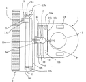
また、本発明の実施例に係わる塗布用布4の支持手段には、昇降機構が設けられる。図7に示すように、塗布用布4の基部は、板状の布ホルダ18bに取り付けられて、床面に向けて垂下されていて、更に、布ホルダ18bの両端部は、水平方向に張り出した支持アーム18a.18aにより支持されている。この一対の支持アーム18a.18aの基端部は、回転軸18cによりそれぞれ連結されて回動可能に構成されている。
【0031】
前記支持アーム18a.18aの基端部の回転軸18cを越えた延長部の上面には、昇降モータ19aにより回転するカム19bが当接され、図8及び図9に示される通り、昇降モータ19aを駆動させることで、支持アーム18a.18a、及び布ホルダ18bを垂直方向に揺動させることができる。
【0032】
また、その他の実施態様としては、図10及び図11に示される通り、ポンプ8を作業部ユニット側に配置した例がある。この場合、作業ユニットが若干大きくなるが、チューブ9の引き回しが簡単になり、メンテナンスに有利である。
【0033】
本発明は、上記の如く構成したことにより、作業ユニット2は、本体1に設けられた作業ユニットの移動用モータ10aを駆動させることで、図12乃至図14の如く、左右方向に走査させることができると共に、作業ユニット2内では、図15及び図16の如く、滴下ノズル3を左右方向に走査することができる。
【0034】
尚、滴下ノズル3の走査範囲と液体塗延手段である布4の幅は、滴下ノズル3が最外側に位置した際に、液体が布4の最外側を越えて飛散または流動により拡散しないよう設定されている。具体的には、液体塗延手段である布4の最外側と滴下ノズル3の最外側の間隔は、ノズル3の移動速度を早くする程、また左右端でのポンプ8の出力を大きくする程、大きく取る必要があることから、ノズル3の移動速度と、左右端でのポンプ8の出力(滴下量)によって変動する。また、これに対して、左右端でポンプ8を停止し、且つスピードを遅くしたとしても、床に滴下された液体は流動により拡散することから、両要因を考慮して、25mm以上、好ましくは30mm以上に設定する。また、間隔を大きく取りすぎると、左右に塗布ムラが生じてかすれることから、100mm以下、好ましくは50mm以下に設定する。
【0035】
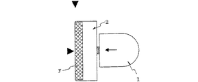
図17乃至図28は、本発明に係わる装置の初期動作の説明図である。ここでは、塗布用布4に対して液体を十分に含浸させる動作を行う。図中▼は、開始位置マークを示している。
【0036】
先ず、図17に示される通り、前述の昇降機構を作動させて液体塗延手段である塗布用布4を下ろし、斜線部の第一の塗布範囲xに液を滴下した後、図18の如く、一旦、その塗布用布4を上げ、矢印の方向に作業ユニット2をスライド移動した後、塗布用布4を下ろす。次に、図19に図示の如く、本体を所定距離前進し、前記第一の塗布範囲xに塗布用布4が来たところで、液体が塗布用布4に適度に含浸する間、実施例では1秒間ほど停止して、塗布用布に液体を染み込ませる。
【0037】
次に、図20の如く、塗布用布4を上げて開始位置まで後退する。この時点で塗布用布4には、液体が含浸した部分である含浸領域yと、含浸していない部分が形成されると共に、床には、塗布用布4が通過していない範囲で、第一の残留部xaが形成される。そして、図21に図示の如く、再び塗布用布4を下ろし、斜線部の第二の塗布範囲xに液体を滴下し、次いで、図22の如く、塗布用布4を上げ、矢印の方向に、作業ユニット2をスライド移動し、中央に戻した後、塗布用布4を下ろす。
【0038】
続いて、図23の如く、所定距離前進し、液滴下位置に塗布用布4が来たところで、前述と同様に1秒間ほど停止して、液体を塗布用布4に染み込ませ、図24の如く、塗布用布4を上げて開始位置まで後退する。この状態で、上記の含浸領域yは塗布用布4の全体になり、図20乃至22の第二の残留部xaは消え、新たに図24のxaが床上の第二の残留部となる。
【0039】
そこで、図25の如く、塗布用布4を上げ、矢印の方向に、作業ユニット2をスライド移動した後、塗布用布4を下ろし、図26の如く、所定距離前進し、残った液を拭った後、作業部を中央に戻しながら、さらに続けて所定距離前進する。この状態で、第二の残留部xaは解消され、図27の如く、塗布用布4を上げて開始位置まで後退した後、図28の如く、塗布用布4を下ろし、前進と液滴下を開始して、塗布作業を開始する。
【0040】
尚、図26で、液残りを拭き取った後、作業部を中央に戻しながら、少し前進させる理由は、布に液を染み込ませるための動作中にも床へ液が塗布されるので、図26での塗布跡を、図28で開始される本番の塗布跡に連続的に滑らかに繋がるようにするためである。
【0041】
また、床に滴下した液のうち、端の液体が残るように、作業ユニット2を移動させて染み込ませるので、塗布用布4の端まで液体が染み込む。そして、図で示すように、最終的には液体が床に残ることがない。
【0042】
図29及び図30は、ロボットによる作業の行程を示す図であり、ジグザグ走行により、作業領域内の床に液を塗布するが、ジグザグ走行には図29のように、右から左へ進む場合と、図30のように左から右へ進む場合がある。本実施例では、作業開始前に布に液を染み込ませる動作を行う際、作業部の移動は、中央位置に対し左側か右側かどちらか一方だけにずれる(前図では、進行方向に向かって左側、つまり紙面の上側)ように行われるので、図29のように、右から左へ進む場合には作業部が左方向にずれるように、図30のように、左から右へ進む場合には作業部が右方向にずれるように制御する。こうすることにより、液が作業領域外に塗布されるのを防止することができる。
【0043】
尚、本実施例ではジグザグ走行を行いながら作業を進めるが、旋回動作を行う場合には、液の滴下を停止し、塗布用布を上げて床から離すことにより不要な塗布を防止し、かつ旋回動作時の床との摩擦を少なくしてスリップを防止している。後退時も、液の滴下を停止し、塗布品質向上のため、塗布用布を上げて床から離す。
【0044】
【発明の効果】
本発明は、前述の如く、走行手段と滴下ノズルの走査手段とを備えると共に、該滴下ノズルを走査させながら走行することにより、床面に消毒液やワックスなどの液体を塗布する液体塗布走行装置において、少なくとも液体塗延手段の長さを作業領域の幅とした際に、作業領域より短い幅で且つ液体塗延手段の最外側を越えて液体が飛散しない範囲で幅方向に移動可能に可動手段により支持された液体滴下ノズルとを備えたことで、ノズルの走査範囲は、液体塗延手段である布の幅よりも十分に狭く設定され、外側への液体の飛散が無く、作業領域の全体に渡り均一な塗布を実現した。また、液体滴下ノズルに液体を供給するチューブを少なくとも作業ユニット内で水平面上に配置し、滴下ノズルの水平面内での移動に応じて水平面内で変位させたので、液体の滴下ノズルに液体を供給するチューブは、高さ方向に最小限に配置されることになり、装置全体の高さを低くすることを可能とし、また装置の外観を優れたものとすることができる。更には、このチューブに対して、チューブと作業ユニット内に搭載された部材との当接部位で滑動する手段を設けたため、チューブが摩擦により部材に引っかかる恐れがなく、装置の安定した動作が確保できる。
【図面の簡単な説明】
【図1】本発明の液体塗布走行装置の側面概要図である。
【図2】本発明の液体塗布走行装置の平面概要図である。
【図3】本発明の液体塗布走行装置の作業ユニットの説明図である。
【図4】本発明の液体塗布走行装置の作業ユニットの説明図である。
【図5】本発明に係わる作業ユニットにおけるノズルの支持状態を示す説明図である。
【図6】本発明に係わる作業ユニットにおけるノズルの支持に使用する補助バネの説明図である。
【図7】本発明に係わる作業ユニットの塗布用布の昇降機構を示す概要図である。
【図8】本発明に係わる作業ユニットの塗布用布の昇降機構を示す説明図である。
【図9】本発明に係わる作業ユニットの塗布用布の昇降機構を示す説明図である。
【図10】本発明の液体塗布走行装置の他の実施例を示す平面概要図である。
【図11】本発明の液体塗布走行装置の他の実施例におけるポンプの支持状態を示す説明図である。
【図12】本発明に係わる作業ユニットの移動状態を示す説明図である。
【図13】本発明に係わる作業ユニットの移動状態を示す説明図である。
【図14】本発明に係わる作業ユニットの移動状態を示す説明図である。
【図15】本発明に係わる作業ユニットにおけるノズルの走査状態を示す説明図である。
【図16】本発明に係わる作業ユニットにおけるノズルの走査状態を示す説明図である。
【図17】本発明の液体塗布走行装置の動作を示す説明図である。
【図18】本発明の液体塗布走行装置の動作を示す説明図である。
【図19】本発明の液体塗布走行装置の動作を示す説明図である。
【図20】本発明の液体塗布走行装置の動作を示す説明図である。
【図21】本発明の液体塗布走行装置の動作を示す説明図である。
【図22】本発明の液体塗布走行装置の動作を示す説明図である。
【図23】本発明の液体塗布走行装置の動作を示す説明図である。
【図24】本発明の液体塗布走行装置の動作を示す説明図である。
【図25】本発明の液体塗布走行装置の動作を示す説明図である。
【図26】本発明の液体塗布走行装置の動作を示す説明図である。
【図27】本発明の液体塗布走行装置の動作を示す説明図である。
【図28】本発明の液体塗布走行装置の動作を示す説明図である。
【図29】本発明の液体塗布走行装置の走行経路の一例を示す説明図である。
【図30】本発明の液体塗布走行装置の走行経路の一例を示す説明図である。
【図31】従来の液体塗布走行装置の側面概要図である。
【図32】従来の液体塗布走行装置の平面概要図である。
【符号の説明】
x 塗布範囲
y 含浸領域
xa 残留部
1 本体
1b 自在キャスタ
1a 車輪
2 作業ユニット
3 滴下ノズル
4 塗布用布
5 スライドレール
5a 支持部材
7 タンク
8 ポンプ
9 チューブ
10a 作業ユニットの移動用モータ
10b プーリ
10c タイミングベルト
12a ノズル走査用のモータ
12b プーリ
12c タイミングベルト
13 近接センサ
14 走査用のパイプ
14a ノズルホルダ
15a チューブホルダ
16a 台板
16b 台板
17 走査補助バネ
17a 引っ掛け部
17b 棒バネ部
17c コイルバネ部
18b 布ホルダ
18a 支持アーム
18c 回転軸
19a 昇降モータ
19b カム
101 本体
101b 自在キャスタ
101a 車輪
102 作業ユニット
103 滴下ノズル
104 塗布用布
105 スライドレール
107 タンク
108 ポンプ
109 チューブ
110a 作業ユニット移動用モータ
110b プーリ
110c タイミングベルト
112a ノズル走査用のモータ
112b プーリ
112c タイミングベルト
114 ノズル移動用スライドレール
114a ノズルホルダ
115 棒バネ[0001]
BACKGROUND OF THE INVENTION
The present invention relates to a method of coating liquids for applying a liquid such as floor disinfectant or wax thoroughly without and uniformly, in particular, a liquid coating traveling device for traveling by scanning the dropping nozzle a method of coating the liquid mainly in the initial operation at the time of using the liquid coating traveling equipment.
[0002]
[Prior art]
Conventionally, various traveling devices for applying a liquid such as wax to the floor surface are known. Generally, when these liquids are applied to the floor surface, in the work area as the vehicle travels. It is desired that the coating be applied widely and uniformly. For example, Japanese Patent Laid-Open No. 299857 “Running Wax Coating and Drying Device” includes a wax pouring pipe that is suspended from a rotating shaft and swings to the left and right. A wax supply and application device is disclosed in which the tip of the dispensing tube is swung from side to side and the wax is widely supplied from the tip to the floor surface in a zigzag manner.
[0003]
According to said apparatus, it is supposed that a wax liquid will be easily supplied to a floor surface zigzag easily by the wax extraction supply apparatus comprised in this way.
[0004]
[Problems to be solved by the invention]
However, the apparatus using the swinging means as described above is bulky, and it is difficult to work in a narrow region where the height direction is limited. At present, the application of wax and disinfectant application liquids is often performed manually, but uniform application is difficult, the amount of liquid used increases, the cleaning cost increases, and more functions are required. There is a demand for a liquid coating apparatus having excellent properties.
[0005]
In view of the present situation and background, the present inventor, as a liquid applicator attached to a self-propelled mobile carriage, previously applied liquid continuously dropped from one nozzle that scans left and right to the floor. An apparatus that employs a method of spreading with one cloth is disclosed. (Technical information magazine “HWT (Human With Technology)” described in the September 1997 issue “Portable Autonomous Mobile Robot Robosanitan”) As shown in FIGS. 31 and 32, this autonomous mobile robot includes
[0006]
However, in the method of spreading the liquid dropped on the floor with a cloth as in this apparatus, in order to make the amount of liquid (the thickness of the coating film) applied to the floor uniform, the liquid is applied to the cloth in advance. It must be soaked. This is because when the work is started with the cloth dry, at first, most of the liquid dropped on the floor is absorbed by the cloth and the coating amount (coating film thickness) decreases. In addition, by soaking the liquid in the entire width of the cloth in advance, the liquid can easily penetrate to the end of the cloth, and uniform application can be performed in the working width direction.
[0007]
Therefore, in the above-mentioned apparatus, the width of the work area (width of the cloth) and the scanning range of the nozzle are set as close as possible so that the liquid is infiltrated into the cloth as much as possible. Since the scanning range is a value very close to the width of the cloth, the liquid may be scattered beyond the width of the cloth, resulting in a disadvantage that the coating quality is deteriorated.
[0008]
In the above apparatus, the tube for supplying the liquid to the nozzle is once lifted upward from the pump discharge port by a bar spring, like a fishing rod and fishing line, so as to correspond to the left and right movement of the nozzle. It was used in a similar way to the threading of the automatic knitting machine, and the arrangement of the tubes was high in the device. In some areas, there was a concern that the device would get stuck when working, and it did not look good. This also applies to JP-A No. 299857 cited above.
[0009]
[Problems to be solved by the present invention]
Liquids application method of the present invention, to solve these problems, the diffusion when the liquid to the floor surface coating, due to scattering and flow of the liquid to the outside of the work area determined by the fabric is liquid Nurinobe means The purpose of this is to improve the coating quality by lowering the height of the apparatus and to reduce the height of the apparatus so that it can be safely operated even under a desk or bed.
[0015]
[Means for Solving the Problems]
The liquid application method of the present invention includes a step of dripping a liquid to a predetermined width as a first application range with a dropping nozzle, and the liquid application in a state where one end in the width direction of the first application range is left. A step of impregnating part of the liquid coating means with liquid and forming a first residual portion by passing through the extending means, and a second application range in the vicinity of the first residual portion by a dropping nozzle as a second application range A step of dripping the liquid into the width, and the liquid coating means passing through the remaining portion of the first coating range while the other end in the width direction of the second coating range remains. The liquid coating means is impregnated with the liquid, and the liquid coating means is passed through the remaining portion of the second application range and wiped.
[0016]
According to the present invention, by the method described above, before the start of the coating operation, after the nozzle is once scanned and the liquid is dropped, the operation unit is moved in the width direction, and further, the forward and backward movement of the main body is combined. In the previous stage of the work, the liquid can be uniformly infiltrated into the cloth which is the liquid spreading means in advance.
[0017]
DETAILED DESCRIPTION OF THE INVENTION
Hereinafter, the liquid application traveling apparatus of the present invention will be described with reference to the drawings of the embodiments.
[0018]
FIG. 1 is a schematic side view of the liquid application traveling apparatus of the present invention, and FIG. 2 is a schematic plan view of the liquid application traveling apparatus of the present invention. As shown in FIG. 1, a plurality of wheels 1 a including a
[0019]
As shown in FIGS. 1 and 2, at the rear of the
[0020]
In addition, a
[0021]
The working
[0022]
[0023]
In addition, it is preferable that the
[0024]
On the other hand, as shown in FIGS. 2 and 3 to 5, the dropping
[0025]
The
[0026]
A
[0027]
Further, as shown in FIG. 5, the end of the
[0028]
Further, a scanning
By this
[0029]
As the
[0030]
The support means for the
[0031]
The
[0032]
As another embodiment, there is an example in which the
[0033]
Since the present invention is configured as described above, the
[0034]
It should be noted that the scanning range of the dripping
[0035]
17 to 28 are explanatory diagrams of the initial operation of the apparatus according to the present invention. Here, an operation of sufficiently impregnating the
[0036]
First, as shown in FIG. 17, the above-described lifting mechanism is operated to lower the
[0037]
Next, as shown in FIG. 20, the
[0038]
Subsequently, as shown in FIG. 23, the
[0039]
Therefore, as shown in FIG. 25, the
[0040]
In FIG. 26, after wiping out the liquid residue, the reason why the work unit is moved forward while returning the center to the center is that the liquid is applied to the floor even during the operation for soaking the cloth into the cloth. This is to continuously and smoothly connect the application trace in FIG. 28 to the actual application trace started in FIG.
[0041]
Further, since the
[0042]
FIG. 29 and FIG. 30 are diagrams showing the work process by the robot. When zigzag travels, the liquid is applied to the floor in the work area. In zigzag travel, the process proceeds from right to left as shown in FIG. In some cases, the process proceeds from left to right as shown in FIG. In this embodiment, when the operation of soaking the liquid into the cloth before starting the work is performed, the movement of the working unit is shifted to either the left side or the right side with respect to the center position (in the previous figure, toward the traveling direction). Left side, that is, the upper side of the drawing), as shown in FIG. 29, when moving from right to left, the working unit is shifted leftward, as shown in FIG. Controls so that the working part is displaced to the right. By doing so, it is possible to prevent the liquid from being applied outside the work area.
[0043]
In this embodiment, the work is carried out while zigzag running, but when performing a turning operation, the dripping of the liquid is stopped, the application cloth is raised and separated from the floor to prevent unnecessary application, and Slip is prevented by reducing friction with the floor during turning. When retreating, stop dripping the liquid, and raise the application cloth and move it away from the floor to improve the application quality.
[0044]
【The invention's effect】
As described above, the present invention includes a liquid application traveling apparatus that includes a traveling unit and a scanning unit for a dropping nozzle, and applies a liquid such as a disinfectant or wax to the floor surface by traveling while scanning the dropping nozzle. In this case, when at least the length of the liquid coating means is the width of the work area, the width is shorter than the work area and is movable in the width direction within the range where the liquid does not scatter over the outermost side of the liquid coating means. By providing the liquid dropping nozzle supported by the means, the scanning range of the nozzle is set to be sufficiently narrower than the width of the cloth as the liquid spreading means, there is no scattering of liquid to the outside, and the work area Uniform coating was realized throughout. In addition, the tube that supplies the liquid to the liquid dropping nozzle is disposed on the horizontal plane at least in the work unit, and is displaced in the horizontal plane according to the movement of the dropping nozzle in the horizontal plane, so the liquid is supplied to the liquid dropping nozzle. The tube to be performed is arranged at a minimum in the height direction, the height of the entire apparatus can be reduced, and the appearance of the apparatus can be improved. In addition, since a means for sliding the tube at the contact portion between the tube and the member mounted in the work unit is provided, the tube does not get caught by the member due to friction, and stable operation of the apparatus is ensured. it can.
[Brief description of the drawings]
FIG. 1 is a schematic side view of a liquid application traveling apparatus of the present invention.
FIG. 2 is a schematic plan view of the liquid application traveling apparatus of the present invention.
FIG. 3 is an explanatory diagram of a work unit of the liquid application traveling apparatus of the present invention.
FIG. 4 is an explanatory diagram of a work unit of the liquid application traveling apparatus of the present invention.
FIG. 5 is an explanatory diagram showing a support state of a nozzle in a work unit according to the present invention.
FIG. 6 is an explanatory diagram of an auxiliary spring used to support a nozzle in a work unit according to the present invention.
FIG. 7 is a schematic view showing a lifting mechanism for a coating cloth of a work unit according to the present invention.
FIG. 8 is an explanatory view showing an elevating mechanism for a coating cloth of a work unit according to the present invention.
FIG. 9 is an explanatory view showing an elevating mechanism for a coating cloth of a work unit according to the present invention.
FIG. 10 is a schematic plan view showing another embodiment of the liquid application traveling apparatus of the present invention.
FIG. 11 is an explanatory view showing a support state of a pump in another embodiment of the liquid application traveling apparatus of the present invention.
FIG. 12 is an explanatory diagram showing a movement state of a work unit according to the present invention.
FIG. 13 is an explanatory diagram showing a movement state of a work unit according to the present invention.
FIG. 14 is an explanatory diagram showing a movement state of a work unit according to the present invention.
FIG. 15 is an explanatory diagram showing a scanning state of a nozzle in a work unit according to the present invention.
FIG. 16 is an explanatory diagram showing a scanning state of nozzles in a work unit according to the present invention.
FIG. 17 is an explanatory view showing the operation of the liquid application traveling apparatus of the present invention.
FIG. 18 is an explanatory view showing the operation of the liquid application traveling apparatus of the present invention.
FIG. 19 is an explanatory view showing the operation of the liquid application traveling apparatus of the present invention.
FIG. 20 is an explanatory view showing the operation of the liquid application traveling apparatus of the present invention.
FIG. 21 is an explanatory view showing the operation of the liquid application traveling apparatus of the present invention.
FIG. 22 is an explanatory view showing the operation of the liquid application traveling apparatus of the present invention.
FIG. 23 is an explanatory view showing the operation of the liquid application traveling apparatus of the present invention.
FIG. 24 is an explanatory view showing the operation of the liquid application traveling apparatus of the present invention.
FIG. 25 is an explanatory view showing the operation of the liquid application traveling apparatus of the present invention.
FIG. 26 is an explanatory view showing the operation of the liquid application traveling apparatus of the present invention.
FIG. 27 is an explanatory view showing the operation of the liquid application traveling apparatus of the present invention.
FIG. 28 is an explanatory view showing the operation of the liquid application traveling apparatus of the present invention.
FIG. 29 is an explanatory diagram showing an example of a travel route of the liquid application travel apparatus of the present invention.
FIG. 30 is an explanatory diagram showing an example of a traveling route of the liquid application traveling apparatus of the present invention.
FIG. 31 is a schematic side view of a conventional liquid application traveling apparatus.
FIG. 32 is a schematic plan view of a conventional liquid application traveling apparatus.
[Explanation of symbols]
x Application range y Impregnation region xa
Claims (1)
前記滴下ノズルで第一の塗布範囲として所定の幅に液体を滴下する工程と、該第一の塗布範囲の幅方向の一方の端部を残留させた状態で前記液体塗延手段を通過させて該液体塗延手段の一部に液体を含浸させると共に第一の残留部を形成する工程と、前記滴下ノズルで第一の残留部の近傍に第2の塗布範囲として所定の幅に液体を滴下する工程と、該第2の塗布範囲の幅方向の他方の端部を残留させた状態で且つ前記第一の塗布範囲の残留部を網羅して液体塗延手段を通過させることで該液体塗延手段の全体に液体を含浸させる工程と、該第2の塗布範囲の残留部に液体塗延手段を通過させて拭き取る工程から成ることを特徴とする液体塗布方法。A main body having traveling means, a work unit connected to the rear of the main body and supported so as to be movable in the width direction of the work area, and provided at an end portion of the work unit and vertically movable by an elevating mechanism A liquid spreading means, and a dropping nozzle supported by the movable means so as to be movable in the width direction of the work area of the work unit, and the application range formed by the dropping nozzle is a liquid spreading means. A liquid application method using a liquid application traveling device formed in the width direction smaller than the formed coating range,
A step of dripping a liquid to a predetermined width as a first application range by the dropping nozzle; and passing the liquid coating means in a state where one end in the width direction of the first application range remains. A step of impregnating a part of the liquid coating means with a liquid and forming a first remaining portion; and dropping the liquid to a predetermined width as a second application range in the vicinity of the first remaining portion by the dropping nozzle And applying the liquid coating means with the other end portion in the width direction of the second coating range remaining and passing the liquid coating means covering the remaining portion of the first coating range. A liquid coating method comprising the steps of impregnating the entire spreading means with a liquid, and passing the liquid spreading means through the remaining portion of the second coating range and wiping it.
Priority Applications (1)
| Application Number | Priority Date | Filing Date | Title |
|---|---|---|---|
| JP2001232832A JP4553524B2 (en) | 2001-06-27 | 2001-06-27 | Liquid application method |
Applications Claiming Priority (1)
| Application Number | Priority Date | Filing Date | Title |
|---|---|---|---|
| JP2001232832A JP4553524B2 (en) | 2001-06-27 | 2001-06-27 | Liquid application method |
Publications (3)
| Publication Number | Publication Date |
|---|---|
| JP2003010088A JP2003010088A (en) | 2003-01-14 |
| JP2003010088A5 JP2003010088A5 (en) | 2005-10-27 |
| JP4553524B2 true JP4553524B2 (en) | 2010-09-29 |
Family
ID=19064685
Family Applications (1)
| Application Number | Title | Priority Date | Filing Date |
|---|---|---|---|
| JP2001232832A Expired - Lifetime JP4553524B2 (en) | 2001-06-27 | 2001-06-27 | Liquid application method |
Country Status (1)
| Country | Link |
|---|---|
| JP (1) | JP4553524B2 (en) |
Cited By (2)
| Publication number | Priority date | Publication date | Assignee | Title |
|---|---|---|---|---|
| CN102886330A (en) * | 2012-10-25 | 2013-01-23 | 昆山允可精密工业技术有限公司 | Oil-wiping device |
| CN111466834A (en) * | 2020-03-26 | 2020-07-31 | 深圳市银星智能科技股份有限公司 | Cleaning robot |
Families Citing this family (36)
| Publication number | Priority date | Publication date | Assignee | Title |
|---|---|---|---|---|
| US8788092B2 (en) | 2000-01-24 | 2014-07-22 | Irobot Corporation | Obstacle following sensor scheme for a mobile robot |
| US8412377B2 (en) | 2000-01-24 | 2013-04-02 | Irobot Corporation | Obstacle following sensor scheme for a mobile robot |
| US6956348B2 (en) | 2004-01-28 | 2005-10-18 | Irobot Corporation | Debris sensor for cleaning apparatus |
| US6690134B1 (en) | 2001-01-24 | 2004-02-10 | Irobot Corporation | Method and system for robot localization and confinement |
| US7571511B2 (en) | 2002-01-03 | 2009-08-11 | Irobot Corporation | Autonomous floor-cleaning robot |
| US8396592B2 (en) | 2001-06-12 | 2013-03-12 | Irobot Corporation | Method and system for multi-mode coverage for an autonomous robot |
| US7429843B2 (en) | 2001-06-12 | 2008-09-30 | Irobot Corporation | Method and system for multi-mode coverage for an autonomous robot |
| US9128486B2 (en) | 2002-01-24 | 2015-09-08 | Irobot Corporation | Navigational control system for a robotic device |
| US8386081B2 (en) | 2002-09-13 | 2013-02-26 | Irobot Corporation | Navigational control system for a robotic device |
| US8428778B2 (en) | 2002-09-13 | 2013-04-23 | Irobot Corporation | Navigational control system for a robotic device |
| US7332890B2 (en) | 2004-01-21 | 2008-02-19 | Irobot Corporation | Autonomous robot auto-docking and energy management systems and methods |
| US7720554B2 (en) | 2004-03-29 | 2010-05-18 | Evolution Robotics, Inc. | Methods and apparatus for position estimation using reflected light sources |
| US20060009879A1 (en) | 2004-06-24 | 2006-01-12 | Lynch James K | Programming and diagnostic tool for a mobile robot |
| US7706917B1 (en) | 2004-07-07 | 2010-04-27 | Irobot Corporation | Celestial navigation system for an autonomous robot |
| US8972052B2 (en) | 2004-07-07 | 2015-03-03 | Irobot Corporation | Celestial navigation system for an autonomous vehicle |
| AU2006214016B2 (en) | 2005-02-18 | 2011-11-10 | Irobot Corporation | Autonomous surface cleaning robot for wet and dry cleaning |
| US8392021B2 (en) | 2005-02-18 | 2013-03-05 | Irobot Corporation | Autonomous surface cleaning robot for wet cleaning |
| US7620476B2 (en) | 2005-02-18 | 2009-11-17 | Irobot Corporation | Autonomous surface cleaning robot for dry cleaning |
| JP2006247467A (en) * | 2005-03-08 | 2006-09-21 | Figla Co Ltd | Self-travelling working vehicle |
| US8930023B2 (en) | 2009-11-06 | 2015-01-06 | Irobot Corporation | Localization by learning of wave-signal distributions |
| EP2267568B1 (en) | 2005-12-02 | 2014-09-24 | iRobot Corporation | Autonomous coverage robot navigation system |
| US8584305B2 (en) | 2005-12-02 | 2013-11-19 | Irobot Corporation | Modular robot |
| ATE534941T1 (en) | 2005-12-02 | 2011-12-15 | Irobot Corp | COVER ROBOT MOBILITY |
| EP2533120B1 (en) | 2005-12-02 | 2019-01-16 | iRobot Corporation | Robot system |
| US8087117B2 (en) | 2006-05-19 | 2012-01-03 | Irobot Corporation | Cleaning robot roller processing |
| US8417383B2 (en) | 2006-05-31 | 2013-04-09 | Irobot Corporation | Detecting robot stasis |
| JP4435761B2 (en) * | 2006-08-04 | 2010-03-24 | 三郎 中郡 | Floor cleaning equipment |
| GB2446917A (en) * | 2007-01-10 | 2008-08-27 | Saburo Chugun | Floor surface cleaning device |
| KR101168481B1 (en) | 2007-05-09 | 2012-07-26 | 아이로보트 코퍼레이션 | Autonomous coverage robot |
| US8800107B2 (en) | 2010-02-16 | 2014-08-12 | Irobot Corporation | Vacuum brush |
| US9427127B2 (en) * | 2013-11-12 | 2016-08-30 | Irobot Corporation | Autonomous surface cleaning robot |
| US11272822B2 (en) | 2013-11-12 | 2022-03-15 | Irobot Corporation | Mobile floor cleaning robot with pad holder |
| US9907449B2 (en) | 2015-03-16 | 2018-03-06 | Irobot Corporation | Autonomous floor cleaning with a removable pad |
| US9265396B1 (en) | 2015-03-16 | 2016-02-23 | Irobot Corporation | Autonomous floor cleaning with removable pad |
| CN215650868U (en) * | 2021-08-02 | 2022-01-28 | 美智纵横科技有限责任公司 | Cleaning cloth component of sweeping robot and sweeping robot with cleaning cloth component |
| CN115089747B (en) * | 2022-07-11 | 2023-07-21 | 郑州凯雪冷链股份有限公司 | High-efficient atomizing disinfection device of freezer business turn over goods |
Citations (4)
| Publication number | Priority date | Publication date | Assignee | Title |
|---|---|---|---|---|
| JPH08308778A (en) * | 1995-05-15 | 1996-11-26 | Mitsuwa Bio Syst Kk | Floor wax applying and drying device |
| JPH09319435A (en) * | 1996-06-03 | 1997-12-12 | Minolta Co Ltd | Movable robot |
| JPH10113318A (en) * | 1996-10-15 | 1998-05-06 | Penguin Wax Kk | Working machine for floor |
| JPH10234635A (en) * | 1997-02-26 | 1998-09-08 | Minolta Co Ltd | Solution applying device |
-
2001
- 2001-06-27 JP JP2001232832A patent/JP4553524B2/en not_active Expired - Lifetime
Patent Citations (4)
| Publication number | Priority date | Publication date | Assignee | Title |
|---|---|---|---|---|
| JPH08308778A (en) * | 1995-05-15 | 1996-11-26 | Mitsuwa Bio Syst Kk | Floor wax applying and drying device |
| JPH09319435A (en) * | 1996-06-03 | 1997-12-12 | Minolta Co Ltd | Movable robot |
| JPH10113318A (en) * | 1996-10-15 | 1998-05-06 | Penguin Wax Kk | Working machine for floor |
| JPH10234635A (en) * | 1997-02-26 | 1998-09-08 | Minolta Co Ltd | Solution applying device |
Cited By (2)
| Publication number | Priority date | Publication date | Assignee | Title |
|---|---|---|---|---|
| CN102886330A (en) * | 2012-10-25 | 2013-01-23 | 昆山允可精密工业技术有限公司 | Oil-wiping device |
| CN111466834A (en) * | 2020-03-26 | 2020-07-31 | 深圳市银星智能科技股份有限公司 | Cleaning robot |
Also Published As
| Publication number | Publication date |
|---|---|
| JP2003010088A (en) | 2003-01-14 |
Similar Documents
| Publication | Publication Date | Title |
|---|---|---|
| JP4553524B2 (en) | Liquid application method | |
| JP2003010088A5 (en) | ||
| US4445451A (en) | Dock device | |
| US20120125378A1 (en) | Bowling Lane Conditioning Machine | |
| KR0131771B1 (en) | Method and apparatus for washing conveyer belt in heat treatment apparatus | |
| JPH1119005A (en) | Building cleaning robot | |
| JP6706226B2 (en) | Large screen cleaning device | |
| JP2997218B2 (en) | High place cleaning machine | |
| JPH08322763A (en) | Glass window cleaning apparatus | |
| JP2009226776A5 (en) | ||
| KR100462790B1 (en) | screen printer clearing apparatus | |
| KR20160116685A (en) | Hot-wind welder for synthetic resin | |
| CN108043658A (en) | A kind of plate glue spreading apparatus | |
| JP2002273281A (en) | Method and apparatus for coating by gondola attaching type external wall surface coating robot | |
| JPH0436897B2 (en) | ||
| JP4621561B2 (en) | Endless track vehicle cleaning system | |
| JP3590894B2 (en) | Automatic soldering method and automatic soldering device | |
| JP4493871B2 (en) | Asphalt solution spraying equipment | |
| JP2593855B2 (en) | Cleaning equipment | |
| JP4285961B2 (en) | Painting equipment for joints | |
| JP4807915B2 (en) | Wall painting equipment | |
| JPS6140795Y2 (en) | ||
| JPH11190004A (en) | Pavement surface finishing machine | |
| JPH0657443U (en) | Automatic tank cleaning device | |
| JPH061272Y2 (en) | Seat cover cleaning device |
Legal Events
| Date | Code | Title | Description |
|---|---|---|---|
| A521 | Written amendment |
Free format text: JAPANESE INTERMEDIATE CODE: A523 Effective date: 20050706 |
|
| RD02 | Notification of acceptance of power of attorney |
Free format text: JAPANESE INTERMEDIATE CODE: A7422 Effective date: 20050706 |
|
| A621 | Written request for application examination |
Free format text: JAPANESE INTERMEDIATE CODE: A621 Effective date: 20080229 |
|
| A977 | Report on retrieval |
Free format text: JAPANESE INTERMEDIATE CODE: A971007 Effective date: 20100402 |
|
| A131 | Notification of reasons for refusal |
Free format text: JAPANESE INTERMEDIATE CODE: A131 Effective date: 20100427 |
|
| A521 | Written amendment |
Free format text: JAPANESE INTERMEDIATE CODE: A523 Effective date: 20100521 |
|
| TRDD | Decision of grant or rejection written | ||
| A01 | Written decision to grant a patent or to grant a registration (utility model) |
Free format text: JAPANESE INTERMEDIATE CODE: A01 Effective date: 20100706 |
|
| A01 | Written decision to grant a patent or to grant a registration (utility model) |
Free format text: JAPANESE INTERMEDIATE CODE: A01 |
|
| A61 | First payment of annual fees (during grant procedure) |
Free format text: JAPANESE INTERMEDIATE CODE: A61 Effective date: 20100713 |
|
| FPAY | Renewal fee payment (event date is renewal date of database) |
Free format text: PAYMENT UNTIL: 20130723 Year of fee payment: 3 |
|
| R150 | Certificate of patent or registration of utility model |
Ref document number: 4553524 Country of ref document: JP Free format text: JAPANESE INTERMEDIATE CODE: R150 Free format text: JAPANESE INTERMEDIATE CODE: R150 |
|
| FPAY | Renewal fee payment (event date is renewal date of database) |
Free format text: PAYMENT UNTIL: 20130723 Year of fee payment: 3 |
|
| EXPY | Cancellation because of completion of term |