JP4498104B2 - Monitoring device, control method thereof, and program - Google Patents
Monitoring device, control method thereof, and program Download PDFInfo
- Publication number
- JP4498104B2 JP4498104B2 JP2004332374A JP2004332374A JP4498104B2 JP 4498104 B2 JP4498104 B2 JP 4498104B2 JP 2004332374 A JP2004332374 A JP 2004332374A JP 2004332374 A JP2004332374 A JP 2004332374A JP 4498104 B2 JP4498104 B2 JP 4498104B2
- Authority
- JP
- Japan
- Prior art keywords
- priority
- preset
- shooting
- camera
- photographing
- Prior art date
- Legal status (The legal status is an assumption and is not a legal conclusion. Google has not performed a legal analysis and makes no representation as to the accuracy of the status listed.)
- Expired - Fee Related
Links
- 238000000034 method Methods 0.000 title claims description 90
- 238000012806 monitoring device Methods 0.000 title claims description 13
- 238000001514 detection method Methods 0.000 claims description 63
- 230000008569 process Effects 0.000 claims description 46
- 125000004122 cyclic group Chemical group 0.000 claims description 30
- 238000012544 monitoring process Methods 0.000 claims description 11
- 238000003384 imaging method Methods 0.000 claims 4
- 238000012545 processing Methods 0.000 description 69
- 230000006870 function Effects 0.000 description 13
- 238000010586 diagram Methods 0.000 description 11
- 230000003287 optical effect Effects 0.000 description 7
- 230000008859 change Effects 0.000 description 6
- 238000012217 deletion Methods 0.000 description 5
- 230000037430 deletion Effects 0.000 description 5
- 230000002093 peripheral effect Effects 0.000 description 4
- 230000007704 transition Effects 0.000 description 4
- 230000005856 abnormality Effects 0.000 description 3
- 238000012508 change request Methods 0.000 description 3
- 238000004891 communication Methods 0.000 description 3
- 230000000007 visual effect Effects 0.000 description 3
- 230000005484 gravity Effects 0.000 description 2
- 230000004044 response Effects 0.000 description 2
- 101000969688 Homo sapiens Macrophage-expressed gene 1 protein Proteins 0.000 description 1
- 102100021285 Macrophage-expressed gene 1 protein Human genes 0.000 description 1
- 238000007796 conventional method Methods 0.000 description 1
- 238000012937 correction Methods 0.000 description 1
- 238000007562 laser obscuration time method Methods 0.000 description 1
- 238000011144 upstream manufacturing Methods 0.000 description 1
Images


Classifications
-
- G—PHYSICS
- G03—PHOTOGRAPHY; CINEMATOGRAPHY; ANALOGOUS TECHNIQUES USING WAVES OTHER THAN OPTICAL WAVES; ELECTROGRAPHY; HOLOGRAPHY
- G03B—APPARATUS OR ARRANGEMENTS FOR TAKING PHOTOGRAPHS OR FOR PROJECTING OR VIEWING THEM; APPARATUS OR ARRANGEMENTS EMPLOYING ANALOGOUS TECHNIQUES USING WAVES OTHER THAN OPTICAL WAVES; ACCESSORIES THEREFOR
- G03B15/00—Special procedures for taking photographs; Apparatus therefor
- G03B15/16—Special procedures for taking photographs; Apparatus therefor for photographing the track of moving objects
-
- G—PHYSICS
- G06—COMPUTING; CALCULATING OR COUNTING
- G06T—IMAGE DATA PROCESSING OR GENERATION, IN GENERAL
- G06T7/00—Image analysis
- G06T7/20—Analysis of motion
- G06T7/254—Analysis of motion involving subtraction of images
-
- H—ELECTRICITY
- H04—ELECTRIC COMMUNICATION TECHNIQUE
- H04N—PICTORIAL COMMUNICATION, e.g. TELEVISION
- H04N23/00—Cameras or camera modules comprising electronic image sensors; Control thereof
- H04N23/60—Control of cameras or camera modules
- H04N23/695—Control of camera direction for changing a field of view, e.g. pan, tilt or based on tracking of objects
-
- G—PHYSICS
- G06—COMPUTING; CALCULATING OR COUNTING
- G06T—IMAGE DATA PROCESSING OR GENERATION, IN GENERAL
- G06T2207/00—Indexing scheme for image analysis or image enhancement
- G06T2207/10—Image acquisition modality
- G06T2207/10016—Video; Image sequence
Landscapes
- Engineering & Computer Science (AREA)
- Physics & Mathematics (AREA)
- General Physics & Mathematics (AREA)
- Multimedia (AREA)
- Computer Vision & Pattern Recognition (AREA)
- Theoretical Computer Science (AREA)
- Signal Processing (AREA)
- Studio Devices (AREA)
- Closed-Circuit Television Systems (AREA)
Description
本発明は、監視すべき領域に侵入した移動体を検出するための監視装置、その制御方法、およびプログラムに関する。 The present invention, monitoring device for detecting a moving object entered the be monitored region, relates to a control method, and program.
現在、コンピュータ制御可能なカメラが市販されており、この種のカメラは、姿勢やズームなどのカメラパラメータの組をプリセットとして登録することができる。こうしたカメラを用いた監視システムにおいては、登録された複数のプリセットに対して順番にカメラ制御を行う機能が設けられており、当該機能は、プリセット巡回と呼ばれている。また、プリセット巡回の各プリセットにおいて画像の動き検知処理を行うシステムがある(例えば特許文献1を参照)。このシステムにおいては、カメラ制御中は動き検知処理を停止させることによって、誤検知の防止が図られている。 Currently, computer-controllable cameras are commercially available, and this type of camera can register a set of camera parameters such as posture and zoom as a preset. Such a monitoring system using a camera is provided with a function of performing camera control in order for a plurality of registered presets, and this function is called preset patrol. In addition, there is a system that performs an image motion detection process in each preset tour (for example, see Patent Document 1). In this system, false detection is prevented by stopping the motion detection process during camera control.
一方、移動物体を追尾する技術に関しても、様々な方法が提案されている。例えば移動物体の色やヒストグラムに注目して追尾制御を行うものがある(例えば特許文献2を参照)。この他にも、移動物体の一部をテンプレートとして記憶して追尾を行う方式や、動きベクトルに注目して追尾を行う方式などが知られている。さらに、プリセット巡回中に各プリセットにおいて画像の動き検知を行い、動きがあるとそのまま移動物体を追尾する手法が提案されている(例えば特許文献3を参照)。これは、カメラ制御に巡回モードと追尾モードの2つのモードを設け、追尾中は巡回制御を停止するものである。
上述した従来の方式においては、全てのプリセットに対して撮影および動き検知が行われる。すなわち、各プリセットに対して等しく巡回が行われる。これにより、監視システムにおいて動き検知による異常発見の効率が低下している。 In the conventional method described above, shooting and motion detection are performed for all presets. That is, an equal cycle is performed for each preset. Thereby, the efficiency of abnormality detection by motion detection in the monitoring system is reduced.
本発明の目的は、移動体が検知された撮影位置が、より高い頻度で撮影されるようなパラメータ巡回を実現し、異常発見の効率を向上することができる監視装置、その制御方法、およびプログラムを提供することにある。 An object of the present invention is to provide a monitoring device, a control method thereof, and a program capable of realizing parameter patrol so that a photographing position where a moving body is detected is photographed at a higher frequency and improving the efficiency of abnormality detection. Is to provide
本発明は、上記目的を達成するため、予め指示された複数の撮影位置に対してそれぞれ設定された優先度に基づいて、カメラが前記複数の撮影位置を巡回するように制御する制御手段と、前記カメラにより撮影された撮影画像から移動体を検知する検知手段と、前記検知手段が移動体を検知した撮影位置の優先度が、前記検知手段が移動体を検知しなかった場合よりも増えるように、前記複数の撮影位置に対してそれぞれ優先度を設定する設定手段と、を有することを特徴とする監視装置を提供する。 The present invention, in order to achieve the above object, a control means based on the priority set respectively with respect to the pre-Me indicated plurality of photographing positions is controlled so as camera patrol the plurality of photographing positions a detection means for detecting a moving object from the image captured by the camera, the priority of the capturing position where the detection unit detects the moving body, more than if the detection means does not detect a moving object as described above, to provide a monitoring device according to claim Rukoto that having a setting means for setting each priority for the plurality of photographing positions.
本発明は、上記目的を達成するため、予め指示された複数の撮影位置に対してそれぞれ設定された優先度に基づいて、カメラが前記複数の撮影位置を巡回するように制御する制御工程と、前記カメラにより撮影された撮影画像から移動体を検知する検知工程と、前記検知工程が移動体を検知した撮影位置の優先度が、前記検知工程が移動体を検知しなかった場合よりも増えるように、前記複数の撮影位置に対してそれぞれ優先度を設定する設定工程とを有することを特徴とする監視装置の制御方法を提供する。 The present invention, in order to achieve the above object, a control process based on the priority set respectively with respect to the pre-Me indicated plurality of photographing positions is controlled so as camera patrol the plurality of photographing positions a detection step of detecting a moving object from the image captured by the camera, the priority of the capturing position in which the detection step detects the moving body, more than when the detection step does not detect the moving object as described above, a control method of the monitoring device according to claim Rukoto which have a a setting step of setting each priority for the plurality of photographing positions.
本発明は、上記目的を達成するため、監視装置の制御方法をコンピュータに実行させるためのコンピュータで読み取り可能なプログラムコードを有するプログラムを提供する。 In order to achieve the above object, the present invention provides a program having a computer readable program code for causing a computer to execute a monitoring device control method.
本発明によれば、移動体が検知された撮影位置が、より高い頻度で撮影されるようなパラメータ巡回を実現できるため、異常発見の効率を向上することができる。 According to the present invention, since it is possible to realize parameter patrol so that a shooting position where a moving body is detected is shot at a higher frequency, it is possible to improve the efficiency of abnormality detection .
以下、本発明の実施の形態について図面を参照しながら説明する。 Hereinafter, embodiments of the present invention will be described with reference to the drawings.
(第1の実施の形態)
図1は本発明の第1の実施の形態に係る自動追尾装置の内部構成を示すブロック図である。本実施の形態においては、複数のプリセットに対して優先順位を設け、プリセット巡回を行う際に、優先順位が高いプリセットに対する巡回回数を増し、プリセットのそれぞれで動きを検知すると、移動物体の追尾を自動的に行う自動追尾装置を説明する。
(First embodiment)
FIG. 1 is a block diagram showing the internal configuration of the automatic tracking apparatus according to the first embodiment of the present invention. In this embodiment, priorities are set for a plurality of presets, and when performing preset patrols, the number of patrols for presets with higher priorities is increased, and if movement is detected in each of the presets, tracking of moving objects is performed. An automatic tracking device that performs automatically will be described.
自動追尾装置は、図1に示すように、カメラ部100と、制御部200とを備える。カメラ部100は、光学系110および雲台120を有し、これらは、制御部200と信号線を介して接続される。カメラ部100は、制御部200からの制御信号に基づいて、光学系110のフォーカス、露出、シャッタースピードなどに関する制御および雲台120の姿勢制御を行う制御回路(図示せず)を備える。カメラ部100は、コンピュータ制御可能な市販のカメラを用いて構成することが可能である。
As shown in FIG. 1, the automatic tracking device includes a
制御部200は、CPU210、ROM220、RAM230、画像取得回路240、符号化回路250、カメラ制御回路260、雲台制御回路270、周辺機器インタフェース(周辺機器I/F)280を有し、これらは内部バスを介して接続される。また、制御部200は、通信部290を介してネットワーク300に画像や装置の状態を送信し、また制御信号を受信する機能を有する。符号化回路250は、画像の符号化を行うものである。画像の符号化の方式としては、JPEGやMPEG1/2/4、H.264などの手法があるが、本実施の形態は符号化の方式に依存するものではない。制御部200は、例えば、パーソナルコンピュータなどから構成することができる。
The
本実施の形態においては、カメラ部100と制御部200とが分離された構成が採用されているが、これに代えて、外観上一体型に構成することも可能である。また、カメラを汎用のパーソナルコンピュータに接続した構成を採用することも可能であり、その場合、パーソナルコンピュータのビデオ回路(図示せず)には外部ディスプレイが接続され、周辺機器I/F280にマウスやキーボードが接続されることなる。
In the present embodiment, a configuration in which the
次に、本実施の形態の自動追尾装置をカメラ制御処理と画像処理との観点から見た場合の構成について図2を参照しながら説明する。図2は図1の自動追尾装置をカメラ制御処理と画像処理との観点から見た場合の構成を示すブロック図である。ここで、図2は、換言すれば、図1に示す構成における画像信号および制御信号の流れを示すためのものであり、図1と同じ機能ブロックには、同一符号が付されている。また、同一の符号が付されているブロックの一部に対する説明は省略する。 Next, a configuration when the automatic tracking device of the present embodiment is viewed from the viewpoint of camera control processing and image processing will be described with reference to FIG. FIG. 2 is a block diagram showing a configuration when the automatic tracking device of FIG. 1 is viewed from the viewpoint of camera control processing and image processing. Here, FIG. 2 is for showing the flow of the image signal and the control signal in the configuration shown in FIG. 1, in other words, the same reference numerals are given to the same functional blocks as those in FIG. In addition, description of a part of the blocks having the same reference numerals is omitted.
制御部200は、図2に示すように、画像処理/カメラ制御部211、画像バッファ221、プリセット巡回情報メモリ222、符号化回路250、カメラ制御回路260、雲台制御回路270、通信部290から構成される。ここで、画像バッファ211およびプリセット巡回情報メモリ222は、図1のRAM230から構成されるものであり、画像処理/カメラ制御部211は、図1のCPU210により構成されるものである。
As shown in FIG. 2, the
カメラ制御信号の流れは、プリセット巡回時と自動追尾時で異なる。プリセット巡回時は、画像処理/カメラ制御部211がプリセット巡回情報メモリ222に記憶されている最初のプリセット巡回情報を読み出し、このプリセット巡回情報に書き込まれている制御量でカメラ部100を制御するようにカメラ制御回路260と雲台制御回路270に対して要求する。この要求を受けた雲台制御回路270は、光学系110が対応するプリセットの姿勢になるように雲台120を駆動し、カメラ制御回路260は、対応する撮影条件で撮影を行うように光学系110を制御する。
The flow of the camera control signal differs between preset tour and automatic tracking. During the preset tour, the image processing /
自動追尾時においては、画像処理/カメラ制御部211は、光学系110により撮影された画像に対して画像処理を施し、その結果に基づいて画面上での追尾対象の位置を決定する。そして、画像処理/カメラ制御部211は、決定された画面上の位置に追尾対象を移動させるための制御信号を生成し、カメラ制御回路260と雲台制御回路270に送出する。カメラ制御回路260および雲台制御回路270は、上記制御信号に基づいて、プリセット巡回時と同様な手順で、カメラ部100を駆動制御する。
At the time of automatic tracking, the image processing /
画像信号の場合、光学系110から画像が取得され、その取得された画像は画像バッファ221に蓄積される。画像バッファ221に蓄積された画像は、符号化回路250で符号化された後に、通信部290を介してネットワーク300に送信される。また、画像バッファ221に蓄積されている画像は、画像処理/カメラ制御部211に入力され、画像処理/カメラ制御部221は、入力された画像に基づいて当該画像の動き検知処理を行う。ここで、画像の動きが検知された場合、画像の動き方向にカメラ部100(光学系110および雲台部120)を向けるための制御信号が生成され、カメラ制御回路260と雲台制御回路270に送信される。これにより、カメラ部100に対する制御が行われる。また、プリセット巡回情報メモリ222内の情報の更新が行われる。このプリセット巡回情報メモリ222内の情報の更新方法については、後に詳細に説明する。
In the case of an image signal, an image is acquired from the
画像の動き検知処理は、例えば画像間の差分を用いて行われる。差分方法としては、隣接フレーム間差分や背景差分が知られている。隣接フレーム間差分の差分演算を用いた方式としては、座標が同じ画素の明度差の絶対値や、JPEG符号化ブロック単位でのDCT係数の差の絶対値和などが用いられ、注目領域に関してこれらの差分結果を積算した値が予め設定された閾値を超えると、動きありとする方式などがある。本実施の形態においては、上記方式に限定されることはなく、任意の方式による動き検知処理を用いることができる。 The image motion detection process is performed using, for example, a difference between images. As a difference method, a difference between adjacent frames and a background difference are known. As a method using the difference calculation of the difference between adjacent frames, the absolute value of the brightness difference of the pixels having the same coordinates, the absolute value sum of the differences of the DCT coefficients in units of JPEG coding blocks, and the like are used. There is a method in which there is a motion when the value obtained by integrating the difference results exceeds a preset threshold value. In the present embodiment, the present invention is not limited to the above method, and motion detection processing by an arbitrary method can be used.
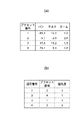
次に、プリセット巡回情報メモリ222(RAM220)に保持される情報について図3を参照しながら説明する。図3(a)はプリセット巡回情報メモリ222に保持されるプリセット情報の一例を示す図、図3(b)はプリセット巡回情報メモリ222に保持される巡回情報の一例を示す図である。
Next, information held in the preset tour information memory 222 (RAM 220) will be described with reference to FIG. FIG. 3A is a diagram showing an example of preset information held in the preset
プリセット巡回情報メモリ222には、プリセット巡回情報が保持され、プリセット巡回情報は、プリセット情報と、巡回情報とに分けられる。プリセット情報は、図3(a)に示すように、プリセット番号、パン、チルト、ズーム値を含む情報からなる。プリセット情報として、上記情報の他に、フォーカス情報や露出情報を含むものすることも可能であるが、説明の都合上、本実施の形態においては、プリセット情報は、自動追尾に必要なパラメータすなわち上記プリセット番号、パン、チルト、ズーム値のみを含む情報とする。
The preset
巡回情報は、図3(b)に示すように、巡回番号、プリセット番号、優先度を含む情報からなる。プリセット巡回は、上記巡回番号の順にプリセット番号に対応するパン、チルト、ズーム値にカメラ部100を制御するものである。ただし、優先度は、当該プリセットにおける動きの発生頻度を表し、動きの発生頻度が高いほど、プリセット巡回中にカメラ制御を行う回数が増されることになる。例えば、優先度が5のプリセットに対しては、巡回サイクル毎に必ずカメラ制御が行われ、優先度が1のプリセットに対しては、5回の巡回サイクルにおいて1回のカメラ制御が行われる。
As shown in FIG. 3B, the tour information includes information including a tour number, a preset number, and a priority. The preset tour controls the
次に、本実施の形態におけるソフトウェア処理手順の概要について図4を参照しながら説明する。図4は図1の自動追尾装置で実行される巡回モードと追尾モード間の状態遷移を模式的に示す図である。 Next, an outline of a software processing procedure in the present embodiment will be described with reference to FIG. FIG. 4 is a diagram schematically showing state transition between the traveling mode and the tracking mode executed by the automatic tracking device of FIG.
本実施の形態の自動追尾装置は、図4に示すように、巡回モード400と追尾モード500とを有する。
As shown in FIG. 4, the automatic tracking device of the present embodiment has a
巡回モード400は、巡回番号の順にプリセット番号に対応するパン、チルト、ズーム値にカメラ部100を制御するプリセット巡回を行うモードであり、当該モードにおいては、プリセット毎に巡回判別処理410,420,…,430が行われる。ここで、巡回判別処理は、対応するプリセットのプリセット巡回情報を参照し、その巡回情報の優先度(図3(b)に示す)に基づいてカメラ制御(図3(a)に示すプリセット情報に基づいたカメラ部100に対するズーム駆動、姿勢制御など)を行うか否かを判別する処理である。ここで、各プリセットには巡回点数が設けられており、巡回点数は、巡回判別処理が行われる毎に優先度分だけ増分され、巡回点数が巡回許可点数に達した時点でカメラ制御が行われる。一度カメラ制御が行われると、巡回点数は、巡回許可点数分だけ下げられる。例えば優先度が5で巡回許可点数が10の場合、2回の巡回サイクルにつき1回のカメラ制御が行われることになる。また、優先度が3で巡回許可点数が10の場合、4回目の巡回サイクルで巡回点数が12となるため、4回目の巡回サイクルにおいてカメラ制御が行われることになる。このとき、巡回点数は巡回許可点数分減ぜられ、その値は2(=12−10)となる。
The
まず、プリセット1に対して巡回判別処理410が行われ、これによりカメラ制御を行わないと判別された場合は、次のプリセット2に対して巡回判別処理420が行われる。これに対し、この巡回判別処理410によりカメラ制御を行うと判別された場合、カメラ部100(ズーム駆動、姿勢位置決めなど)の動作終了後に動き検知処理450が開始される。動き検知処理450の開始から一定時間経過しても移動物体すなわち画像の動きが検知されない場合、プリセット2の巡回判別処理420が開始される。このようにして、各プリセットに対する巡回判別処理が順に行われ、それぞれの巡回判別処理の結果に応じてカメラ制御と動き検知450と実施される。最後のプリセットNに対する巡回判別処理が終了すると、1回の巡回サイクルが終了したことになり、次の巡回サイクルを開始するために、再度プリセット1からの巡回判別処理が繰り返し行われる。
First, the
ここで、図4に示すように、プリセット2に対する巡回判別処理420によるカメラ制御後の動き検知処理450において動き(移動物体)が検知されたとすると、プリセット巡回情報の更新処理460後に、巡回モード400から追尾モード500への遷移が行われる。プリセット巡回情報の更新処理460は、巡回情報の優先度を動き検知結果に基づいて変更する処理である。このプリセット2に対する巡回判別処理420によるカメラ制御後の動き検知処理450により動きが検知された場合、図3(b)に示すように、プリセット番号2に対する優先度は3から4に上げられる。これに対し、複数回の動き検知処理450の試行結果、動きが検知されなかった場合、プリセット番号2に対する優先度が3から2に下げられる。通常動きが検知されないことが多いため優先度を下げる場合は例えば1日間動きが検知されない場合には優先度を下げるなどすることもできる。優先度は、動きが発生する頻度を表すものと考えることができ、この優先度の値を更新することによって、動きが発生する頻度に応じた動的な変化に対応することが可能になる。
Here, as shown in FIG. 4, if a motion (moving object) is detected in the
動き検知処理450により動きが検知されたことに応じて遷移された追尾モード500においては、例えば動き検知処理450で得られた動き情報に基づいて画像上で動きがあった領域が求められ、その重心点が画像中央にくるようにカメラ制御処理520が行われる。そして、カメラ制御処理520の終了後、カメラ部100の動作(姿勢など)が安定するのを待って動き検知処理510が行われ、それにより動きが検知されると、再びカメラ制御処理520が行われる。このように、追尾モード500においては、動き検知処理510とカメラ制御処理520とが交互に繰り返して行われる。これは、カメラ110の移動中にフレーム間差分処理を行うと、カメラ110の移動による誤検知が生じるからである。追尾方法としては、上記に限定されることはなく、例えば移動物体の色や柄、エッジなどの特徴量を記憶して継続的に追尾を行う方式を用いてもよい。
In the
動き検知処理510による動き検知が失敗すると、追尾モード500から巡回モード400への遷移が行われ、再びプリセット巡回が開始される。ただし、動き検知処理510による動き検知が失敗したと判別する場合は、動き検知が最低何回か連続して失敗した場合である。また、追尾モード500から巡回モード400へ戻る際には、図4に示すように、最初のプリセット1に対する巡回判別処理410へ戻る。また、追尾モード500へ遷移した際のプリセットの巡回判別処理、最も優先度が高いプリセットの巡回判別処理などへ戻るようにしてもよい。
If the motion detection by the
次に、本実施の形態における巡回モード400および追尾モード500の処理について図5および図6を参照しながら説明する。図5および図6は図1の移動体追尾装置の巡回モード400および追尾モード500の処理手順を示すフローチャートである。ここで、図5のステップS501からステップS508までの手順は、巡回モード400に対応する手順であり、図6のステップS510からステップS516までの手順は、追尾モード500に対応する手順である。各図のフローチャートで示す手順は、画像処理/カメラ制御部211(CPU210)により実行されるものである。
Next, processing in the traveling
画像処理/カメラ制御部211は、図5に示すように、まずステップS501において、最初のプリセットに対して上述した方法で巡回判別処理を行う。そして、画像処理/カメラ制御部211は、ステップS502において、上記巡回判別処理の結果に基づいて、カメラ制御を行うか否かを判定する。ここで、カメラ制御を行わないと判定された場合、画像処理/カメラ制御部211は、上記ステップS501に戻り、次のプリセットの巡回判別処理を行う。
As shown in FIG. 5, the image processing /
上記ステップS502においてカメラ制御を行うと判定された場合、画像処理/カメラ制御部211は、ステップS503において、カメラ110がプリセット位置に移動するよう制御し、続くステップS504において、カメラ110で撮影された1枚の画像を画像バッファ221に保存する。
If it is determined in step S502 that camera control is to be performed, the image processing /
次いで、画像処理/カメラ制御部211は、ステップS505において、動き検知処理を行い、続くステップS506において、上記動き検知処理により動きが検知されたか否かを判定する。ここで、動きが検知されなかった場合、画像処理/カメラ制御部211は、ステップS507において、次のプリセット位置へ巡回移動する時間が経過したか否かを判定する。ここで、上記時間が経過していなければ、画像処理/カメラ制御部211は、上記ステップS505に戻り、動き検知処理を継続する。これに対し、上記時間が経過していれば、画像処理/カメラ制御部211は、上記ステップS501に戻り、次のプリセット位置に移動するか否かの判別処理を開始する。
Next, the image processing /
上記ステップS506において動きが検知された場合、画像処理/カメラ制御部211は、ステップS508において、上述した方法により現在のプリセットの優先度を更新し、追尾モードへ遷移するために、図6のステップS514へ進む。
If a motion is detected in step S506, the image processing /
画像処理/カメラ制御部211は、ステップS514において、画像処理によりカメラ制御量を求める。ここでは、上述したように、画像上での動き領域の重心位置が画面中央に移動するようにカメラ制御量を求め、この求められたカメラ制御量を用いてカメラ制御を行う。そして、画像処理/カメラ制御部211は、次の動き検知処理を開始し、ステップS510において、画像を取得し、続くステップS511において、動き検知処理を行う。この動き検知処理は、上記ステップS504のものと同じである。
In step S514, the image processing /
次いで、画像処理/カメラ制御部211は、ステップS512において、上記動き検知処理により動きが検知されたか否かを判定する。ここで、動きが検知された場合、画像処理/カメラ制御部211は、ステップS513において、追尾処理の連続失敗回数を0に初期化し、続くステップS514において、上述したカメラ制御を行う。
Next, in step S512, the image processing /
上記ステップS512において動きが検知されなかった場合、画像処理/カメラ制御部211は、ステップS515において、追尾処理の連続失敗回数を1増加する。そして、画像処理/カメラ制御部211は、連続失敗回数が閾値Cth以上であるか否かの判定を行う。ここで、連続失敗回数が閾値Cth以上である場合、画像処理/カメラ制御部211は、巡回モードに遷移するために、上記ステップS501へ進む。これに対し、連続失敗回数が閾値Cth未満である場合は、画像処理/カメラ制御部211は、上記ステップS510に戻り、追尾モードを継続する。
If no motion is detected in step S512, the image processing /
以上より、本実施の形態によれば、プリセット巡回中に、プリセット毎に対応付けられている優先度に基づいてカメラ制御を行うか否かの判定を行うので、動き検知の観点から、各プリセットを差別化することができ、動き検知による異常発見を効率的に行うと共に、装置に余分な負荷(動き検知のための処理に掛かる負荷)を掛けることを未然に防止することができる。また、カメラ制御が行われたプリセットにおいて動きが検知されると、移動体を追尾するので、プリセット毎に高い精度での移動物体検出および追尾処理を行うことができる。 As described above, according to the present embodiment, during preset tour, since it is determined whether to perform camera control based on the priority associated with each preset, from the viewpoint of motion detection, each preset Thus, it is possible to efficiently detect anomalies through motion detection and to prevent the apparatus from being subjected to an extra load (a load for processing for motion detection). In addition, when a motion is detected in a preset in which camera control is performed, the moving body is tracked, so that it is possible to perform moving object detection and tracking processing with high accuracy for each preset.
(第2の実施の形態)
次に、本発明の第2の実施の形態について図7および図8を参照しながら説明する。図7は本発明の第2の実施の形態に係る自動追尾装置において優先度を動き検知発生確率とした場合のプリセット巡回情報の一例を示す図、図8は図7のプリセット巡回情報に代わるプリセット巡回情報の他の例を示す図である。
(Second Embodiment)
Next, a second embodiment of the present invention will be described with reference to FIGS. FIG. 7 is a diagram showing an example of preset tour information when the priority is set as the motion detection occurrence probability in the automatic tracking device according to the second embodiment of the present invention, and FIG. 8 is a preset in place of the preset tour information in FIG. It is a figure which shows the other example of circulation information.
本実施の形態においては、実際の動き発生現象により忠実な巡回パターンを設定するために、プリセット巡回における優先度として第1の実施の形態の動き検知の発生頻度に代えて動き検知発生確率が用いられる。 In this embodiment, in order to set a faithful cyclic pattern by an actual motion occurrence phenomenon, the motion detection occurrence probability is used as the priority in the preset tour instead of the motion detection occurrence frequency of the first embodiment. It is done.
具体的には、図7に示すように、プリセット巡回における優先度として、動き検知発生確率が用いられ、優先度すなわち動き検知発生確率の値は、0%より大きくかつ100%以下の値とされる。ここで、プリセット巡回時に動き検知を行うか否かは、上記第1の実施の形態と同様に、巡回毎に優先度を加算し、その値が100%に達すると、当該プリセット位置での巡回を行うという手法を用いてもよい。また、「何回かに1回」ではなく、優先度として保持されている動き検知発生率をそのまま巡回の確率(プリセットにおけるカメラ制御を行う確率)として用いることもできる。この場合、プログラムの実装上は、乱数関数を用いて優先度として保持されている動き検知発生率で、「巡回する」という指示を出力するようにすればよい。 Specifically, as shown in FIG. 7, the motion detection occurrence probability is used as the priority in the preset tour, and the priority, that is, the value of the motion detection occurrence probability is greater than 0% and less than 100%. The Here, whether or not to perform motion detection during preset tour is determined by adding a priority for each tour as in the first embodiment, and when the value reaches 100%, the tour at the preset position is performed. You may use the method of performing. Also, instead of “once every several times”, the motion detection occurrence rate held as the priority can be used as it is as a traveling probability (probability of performing camera control in the preset). In this case, on the implementation of the program, an instruction to “circulate” may be output at a motion detection occurrence rate held as a priority using a random number function.
また、本実施の形態においては、図8に示すように、優先度の値の範囲を0%から100%までの範囲に広げることが可能である。この場合、動き検知発生率が0%とは、当該プリセットへのカメラ制御は行うが動き検知処理は行わず、時間が経過したら自動的に次のプリセットに移動するという、単純なプリセット巡回動作となる。 In the present embodiment, as shown in FIG. 8, the range of priority values can be expanded to a range from 0% to 100%. In this case, a motion detection occurrence rate of 0% is a simple preset patrol operation in which the camera control is performed for the preset but the motion detection process is not performed, and automatically moves to the next preset when time elapses. Become.
(第3の実施の形態)
次に、本発明の第3の実施の形態について図9〜図11を参照しながら説明する。図9は本発明の第3の実施の形態に係る自動追尾装置のプリセット設定および巡回設定を行うためのユーザインタフェース画面の一例を示す図、図10および図11は図9のユーザインタフェースを用いてプリセット設定および巡回設定を行うための手順を示すフローチャートである。
(Third embodiment)
Next, a third embodiment of the present invention will be described with reference to FIGS. FIG. 9 is a diagram showing an example of a user interface screen for performing preset setting and patrol setting of the automatic tracking device according to the third embodiment of the present invention, and FIGS. 10 and 11 use the user interface of FIG. It is a flowchart which shows the procedure for performing preset setting and patrol setting.
本実施の形態は、プリセット設定および巡回設定を行うためのGUI(グラフィカル・ユーザインタフェース)を有する。このGUIは、所定のOS(オペレーティングシステム)上に実装されるアプリケーションソフトウェアにより実現されるものであり、このアプリケーションソフトウェアは、本自動追尾装置に実装されてもよいし、本自動追尾装置に対してネットワーク300経由で接続されるクライアントPCに実装されてもよい。よって、本自動追尾装置または上記クライアントPC上で上記GUIを用いてプリセット設定および巡回設定を行うことが可能である。
This embodiment has a GUI (graphical user interface) for performing preset setting and patrol setting. This GUI is realized by application software installed on a predetermined OS (operating system), and this application software may be installed in the automatic tracking device, or for the automatic tracking device. It may be mounted on a client PC connected via the
プリセット設定および巡回設定を行う際には、上記GUIにより、例えば図9(a)に示すようなダイアログ800が表示される。ダイアログ800には、プリセット位置表示810とプリセット/巡回設定タブ820とが含まれる。プリセット位置表示810は、カメラ部100が物理的に制御可能な視野範囲を表示し、視野を表す矩形を用いてプリセット時のパン、チルト、ズーム値を表示する。プリセット/巡回設定タブ820は、プリセット設定と巡回設定を選択するためのものであり、図9(a)に示す画面は、巡回設定が選択されている画面を示す。プリセット設定は、プリセットにおけるパン、チルト、ズームなどの設定を行うためのものである。巡回設定は、巡回するプリセットの登録や編集を行うためのものである。
When preset setting and patrol setting are performed, a
次に、巡回設定の方法を詳細に説明する。まず、プリセット/巡回設定タブ820において「巡回」が選択される。このタブは、巡回番号選択821、プリセット巡回一覧822、巡回順序変更ボタン823,824、プリセット巡回追加ボタン825、プリセット巡回詳細ボタン826、プリセット巡回削除ボタン827などを含む。プリセット巡回は複数の巡回設定が可能であり、巡回設定毎に、巡回番号選択821により、設定を行う巡回番号が選択される。本例においては、「巡回2」が選択されている。
Next, the method for setting the tour will be described in detail. First, “tour” is selected in the preset /
巡回番号が選択されると、登録されているプリセットの一覧が巡回する順序に従ってプリセット巡回一覧表示822に表示される。ここで、表示されているプリセットのそれぞれに対して巡回する順番を変更することができる。この場合、順番を変更するプリセットの1つが選択され、巡回順番変更ボタン823,824により、選択された1つのプリセットの順番が上流または下流側に変更される。また、選択されたプリセットに対して削除ボタン827を押下することによって、当該プリセットを一覧から削除することができる。
When a tour number is selected, a list of registered presets is displayed on the preset
プリセットの編集時には、詳細ボタン826が押下される。これにより、図9(b)に示すようなプリセット巡回詳細設定ダイアログ830が表示される。同様に、プリセットの追加時には、追加ボタン825が押下され、プリセット巡回の追加ダイアログが表示され、追加が可能となる。追加されたプリセットは、プリセット巡回一覧表示822に表示されている一覧の最後に追加される。この追加ダイアログは、プリセット詳細設定ダイアログとタイトルのみが異なり、基本的な動作は同じものである。
When editing a preset, a
プリセット巡回詳細ダイアログ830においては、プリセット番号831の選択設定、停止時間832の選択設定、巡回の優先度833の選択設定をそれぞれ行うことが可能である。これらの設定が行われた後に、「OKボタン」が押下されると、設定が確定され、プリセット巡回一覧表示822に表示されているプリセット巡回一覧中の対応するプリセットに付属する情報が更新される。また、プリセット巡回の追加ダイアログが起動された場合には、同様の手順により、新たなプリセットが登録されることになる。
In the preset
次に、プリセット位置表示810について説明する。プリセット位置表示810は、プリセット巡回一覧表示822に表示されている一覧のプリセットのパン、チルト、ズーム値を、視野範囲とする矩形を表示したものである。図9(a)においては、プリセット1からプリセット4までの4つのプリセットに対応する矩形811〜814が表示され、プリセット巡回一覧表示822に表示されている一覧において現在選択中のプリセット3に対応する矩形813が強調表示されている。このプリセットを表す矩形の位置やサイズは、ドラッグ操作などにより変更することができる。プリセットに対応する矩形の表示中には、プリセット番号、巡回番号および優先度が数値で表示される。これらの情報は、常時表示するようにしてもよいし、マウスカーソルを当該プリセット矩形領域上に重ねたときに小ウィンドウとして表示するようにしてもよい。また、選択状態にあるプリセットの矩形領域上でマウスを右クリックすると、図9(c)に示すようなコンテキストメニュー840が表示され、このコンテキストメニュー840上で順番の変更、優先度の変更、削除などを行うことが可能である。
Next, the
次に、本実施の形態における上記GUIを用いてプリセット設定および巡回設定を行う際の動作について図10および図11を参照しながら説明する。ここでは、プリセット設定および巡回設定をネットワーク300上のクライアントPCで行う場合を説明する。
Next, an operation when performing preset setting and cyclic setting using the GUI in the present embodiment will be described with reference to FIGS. 10 and 11. Here, a case where preset setting and patrol setting are performed by a client PC on the
クライアントPCは、図10に示すように、まずステップS901において、初期化を行い、続くステップS902において、サーバすなわち自動追尾装置との接続処理を行う。そして、クライアントPCは、ステップS903において、サーバとの接続が成功したか否かを判定する。ここで、サーバとの接続が失敗した場合、クライアントPCは、ステップS904において、エラーメッセージの表示などの例外処理を行い、本処理を終了する。 As shown in FIG. 10, the client PC first performs initialization in step S901, and performs connection processing with a server, that is, an automatic tracking device, in subsequent step S902. In step S903, the client PC determines whether the connection with the server is successful. If the connection with the server fails, the client PC performs an exception process such as displaying an error message in step S904, and ends the process.
上記ステップS903においてサーバとの接続が成功したと判定された場合、クライアントPCは、ステップS905において、イベント待ちを行う。ここで、イベントが発生すると、クライアントPCは、ステップS906において、発生したイベントがプリセット位置表示810上のプリセットの矩形領域を選択するものであるか否かを判定する。ここで、発生したイベントがプリセットの矩形領域を選択するものであれば、クライアントPCは、ステップS907において、選択された矩形領域を選択状態にするとともに、巡回設定のプリセット巡回一覧表示822に表示されている一覧中の対応するプリセットを選択状態にする。そして、クライアントPCは、上記ステップS905に戻り、次のイベント発生を待つ。
If it is determined in step S903 that the connection with the server is successful, the client PC waits for an event in step S905. When an event occurs, the client PC determines in step S906 whether or not the event that has occurred selects a preset rectangular area on the
上記ステップS906において発生したイベントがプリセット位置表示810上のプリセットの矩形領域を選択するものでないと判定された場合、クライアントPCは、ステップS908において、発生したイベントが選択された矩形表示に対する変更要求(選択された矩形に対して行われたドラッグ操作によるもの)であるか否かを判定する。ここで、発生したイベントが選択された矩形表示に対する変更要求である場合、クライアントPCは、ステップS909において、ドラッグ操作に応じて選択された矩形の位置やサイズを変更する。そして、クライアントPCは、上記ステップS905へ戻り、次のイベント発生を待つ。
If it is determined that the event that occurred in step S906 does not select a preset rectangular area on the
上記ステップS908において発生したイベントが選択された矩形表示に対する変更要求でないと判定された場合、クライアントPCは、ステップS910において、発生したイベントが選択された矩形に対するコンテキストメニューの表示要求(矩形を選択した状態でマウスの右クリックによるもの)であるか否かを判定する。ここで、発生したイベントが選択された矩形に対するコンテキストメニューの表示要求である場合、クライアントPCは、ステップS911において、コンテキストメニュー上で詳細メニューが(選択されたか否か(詳細ボタン826が押下されたか否か)を判定する。
If it is determined in step S908 that the event that has occurred is not a change request for the selected rectangular display, the client PC, in step S910, displays a context menu display request for the rectangle in which the generated event has been selected (the rectangle has been selected. It is determined whether or not it is due to a right mouse click). If the event that has occurred is a request for displaying a context menu for the selected rectangle, the client PC determines whether or not the detail menu is selected on the context menu (whether or not the
上記ステップS911において詳細メニューが選択されていないと判定された場合、クライアントPCは、ステップS917において、その他のメニュー処理を行い、上記ステップS905へ戻る。ここで、その他のメニュー処理としては、巡回順序の変更、優先度の変更、および削除がある。最初の2つにおいては、コンテキストメニュー上で選択された値が内部データとして反映される。これに対し、削除が選択された場合は、当該プリセットがプリセット巡回リストから削除される。この場合、当該プリセットは、巡回タブのプリセット巡回一覧表示822の一覧から削除される。
If it is determined in step S911 that the detailed menu is not selected, the client PC performs other menu processing in step S917 and returns to step S905. Here, as other menu processes, there are a change of the tour order, a change of priority, and a deletion. In the first two, the value selected on the context menu is reflected as internal data. On the other hand, when deletion is selected, the preset is deleted from the preset circulation list. In this case, the preset is deleted from the list of the preset
上記ステップS911において詳細メニューが選択された場合、クライアントPCは、ステップS914において、プリセット巡回詳細設定ダイアログ830を表示する。そして、クライアントPCは、上記プリセット巡回設定詳細ダイアログ830上で入力された巡回情報に応じて対応するパラメータを変更した後に、上記ステップS905へ戻り、次のイベントを待つ。
If the detailed menu is selected in step S911, the client PC displays a preset patrol detailed setting
上記ステップS910において発生したイベントがコンテキストメニューの表示要求でないと判定された場合、クライアントPCは、ステップS912において、発生したイベントが巡回タブ上の各種ボタンの押下イベントであるか否かを判定する。ここで、発生したイベントが巡回タブ上の各種ボタンの押下イベントである場合、クライアントPCは、ステップS913において、発生したイベントが詳細ボタン826または追加ボタン825の押下イベントであるか否かを判定する。
If it is determined in step S910 that the event that has occurred is not a context menu display request, the client PC determines in step S912 whether or not the event that has occurred is a press event of various buttons on the tour tab. If the event that has occurred is a pressing event for various buttons on the tour tab, the client PC determines in step S913 whether the event that has occurred is a pressing event for the
上記ステップS913において発生したイベントが詳細ボタン826または追加ボタン825の押下イベントであると判定された場合、クライアントPCは、ステップS914において、プリセット巡回詳細設定ダイアログ830を表示する。追加ボタン825が押下された場合、追加設定ダイアログが表示される。この追加設定ダイアグ上での手順は、実質的には、上述した詳細設定の場合と同じである。
If it is determined that the event that occurred in step S913 is a pressing event of the
上記ステップS913において発生したイベントが詳細ボタン826または追加ボタン825の押下イベントでないと判定された場合、クライアントPCは、ステップS915において、その他のボタン処理を行い、上記ステップS905へ戻る。ここで、他のボタン処理としては、リストの「上へ」、リストの「下へ」、「削除」などがある。リストの「上へ」と「下へ」は、巡回の順序を前後させ、リスト上での位置表示を変更するものである。また、削除は、巡回リストから当該プリセットを削除する処理である。この場合は、プリセット位置表示810上の対応するプリセット表示矩形も消去される。
If it is determined that the event that occurred in step S913 is not a pressing event of the
上記ステップS912において発生したイベントが巡回タブ上の各種ボタンの押下イベントでないと判定された場合、クライアントPCは、ステップS916において、その他の処理を行う。ここで、他の処理としては、巡回番号選択821、プリセット巡回一覧822などに対する処理がある。巡回番号選択821が操作されると、巡回セットが変更される。また、プリセット巡回一覧822上でプリセットが指定されると、指定されたプリセットが選択状態となり、また、プリセット位置表示810における対応するプリセットを表す矩形が選択状態になる。そして、クライアントPCは、上記ステップS905へ戻る。
If it is determined that the event generated in step S912 is not an event of pressing various buttons on the tour tab, the client PC performs other processing in step S916. Here, as other processes, there are processes for the
このように、本実施の形態によれば、プリセット巡回に必要な、プリセットの一覧、巡回の順序、プリセット位置の微修正、優先度をGUIにより容易に設定することができる。 As described above, according to the present embodiment, it is possible to easily set the preset list, the order of the tour, the fine correction of the preset position, and the priority necessary for the preset tour by the GUI.
なお、上記各実施の形態においては、自動追尾装置を説明したが、これに限らず、例えば追尾モードを省いた巡回モードのみを有する監視装置の場合において、上記巡回モード400を設ければ、動き検知の観点から、各プリセットを差別化することができ、装置に余分な負荷(動き検知のための処理に掛かる負荷)を掛けることを未然に防止することができるという効果を発揮する監視装置を提供することができる。 In each of the above embodiments, the automatic tracking device has been described. However, the present invention is not limited to this. For example, in the case of a monitoring device that has only a cyclic mode without the tracking mode, From the viewpoint of detection, there is a monitoring device that can differentiate each preset, and can prevent the device from being subjected to an extra load (load for processing for motion detection). Can be provided.
なお、本発明の目的は、前述した各実施の形態の機能を実現するソフトウェアのプログラムコードを記録した記憶媒体(または記録媒体)を、システムあるいは装置に供給し、そのシステムあるいは装置のコンピュータ(またはCPUやMPU)が記憶媒体に格納されたプログラムコードを読み出し実行することによっても、達成されることはいうまでもない。この場合、記憶媒体から読み出されたプログラムコード自体が前述した実施形態の機能を実現することになり、そのプログラムコードを記憶した記憶媒体は本発明を構成することになる。 An object of the present invention is to supply a storage medium (or recording medium) that records a program code of software that realizes the functions of the above-described embodiments to a system or apparatus, and to perform a computer (or a computer) Needless to say, this can also be achieved by the CPU and MPU) reading and executing the program code stored in the storage medium. In this case, the program code itself read from the storage medium realizes the functions of the above-described embodiments, and the storage medium storing the program code constitutes the present invention.
また、プログラムコードを供給するための記憶媒体としては、例えば、フロッピー(登録商標)ディスク、ハードディスク、光磁気ディスク、CD−ROM、CD−R、CD−RW、DVD−ROM、DVD−RAM、DVD−RW、DVD+RW、磁気テープ、不揮発性のメモリカード、ROM等を用いることができる。または、プログラムコードを、ネットワークを介してダウンロードしてもよい。 Examples of the storage medium for supplying the program code include a floppy (registered trademark) disk, a hard disk, a magneto-optical disk, a CD-ROM, a CD-R, a CD-RW, a DVD-ROM, a DVD-RAM, and a DVD. -RW, DVD + RW, magnetic tape, nonvolatile memory card, ROM, etc. can be used. Alternatively, the program code may be downloaded via a network.
また、コンピュータが読み出したプログラムコードを実行することにより、前述した実施形態の機能が実現されるだけでなく、そのプログラムコードの指示に基づき、コンピュータ上で稼働しているオペレーティングシステム(OS)などが実際の処理の一部または全部を行い、その処理によって前述した実施形態の機能が実現される場合も含まれる。 Further, by executing the program code read by the computer, not only the functions of the above-described embodiments are realized, but also an operating system (OS) running on the computer based on the instruction of the program code. A case where part or all of the actual processing is performed and the functions of the above-described embodiments are realized by the processing is also included.
さらに、記憶媒体から読み出されたプログラムコードが、コンピュータに挿入された機能拡張カードやコンピュータに接続された機能拡張ユニットに備わるメモリに書込まれた後、そのプログラムコードの指示に基づき、その機能拡張カードや機能拡張ユニットに備わるCPUなどが実際の処理の一部または全部を行い、その処理によって前述した実施形態の機能が実現される場合も含まれる。 Furthermore, after the program code read from the storage medium is written into a memory provided in a function expansion card inserted into the computer or a function expansion unit connected to the computer, the function is determined based on the instruction of the program code. The case where the CPU of the expansion card or the function expansion unit performs part or all of the actual processing and the functions of the above-described embodiments are realized by the processing is also included.
100 カメラ部
110 光学系
120 雲台
200 制御部
210 CPU
211 画像処理/カメラ制御部
220 ROM
222 プリセット巡回情報メモリ
230 RAM
260 カメラ制御回路
270 雲台制御回路
DESCRIPTION OF
211 Image processing /
222 Preset
260
Claims (13)
前記カメラにより撮影された撮影画像から移動体を検知する検知手段と、
前記検知手段が移動体を検知した撮影位置の優先度が、前記検知手段が移動体を検知しなかった場合よりも増えるように、前記複数の撮影位置に対してそれぞれ優先度を設定する設定手段と、
を有することを特徴とする監視装置。 Control means for controlling the camera to go around the plurality of shooting positions based on the priority set for each of the plurality of shooting positions designated in advance;
Detecting means for detecting a moving body from a captured image captured by the camera;
Setting means for setting the priority for each of the plurality of photographing positions so that the priority of the photographing position at which the detecting means has detected the moving body is higher than that when the detecting means has not detected the moving body. When,
The monitoring apparatus characterized by having.
前記カメラにより撮影された撮影画像から移動体を検知する検知工程と、
前記検知工程が移動体を検知した撮影位置の優先度が、前記検知工程が移動体を検知しなかった場合よりも増えるように、前記複数の撮影位置に対してそれぞれ優先度を設定する設定工程とを有することを特徴とする監視装置の制御方法。 A control step of controlling the camera to go around the plurality of shooting positions based on the priority set for each of the plurality of shooting positions designated in advance;
A detection step of detecting a moving object from a captured image captured by the camera;
Setting step for setting priorities for each of the plurality of shooting positions so that the priority of the shooting position at which the detection process has detected the moving body is higher than that at the time when the detection process has not detected the moving body. And a method for controlling the monitoring device.
前記制御工程が第1の撮影位置から検知された移動体の追尾をはじめた後、前記検知工程により移動体が連続して検知されない回数が閾値に達すると、前記予め指示された撮影位置の撮影を再び開始することを特徴とする請求項7に記載の監視装置の制御方法。 The control step tracks the mobile body detected in the detection step,
After the control step starts tracking the moving body detected from the first shooting position, when the number of times the moving body is not continuously detected by the detection step reaches a threshold, shooting at the shooting position designated in advance is performed. The monitoring apparatus control method according to claim 7, wherein the monitoring apparatus is started again.
Priority Applications (2)
| Application Number | Priority Date | Filing Date | Title |
|---|---|---|---|
| JP2004332374A JP4498104B2 (en) | 2004-11-16 | 2004-11-16 | Monitoring device, control method thereof, and program |
| US11/280,146 US7433588B2 (en) | 2004-11-16 | 2005-11-15 | Camera control apparatus, camera control method, program and storage medium |
Applications Claiming Priority (1)
| Application Number | Priority Date | Filing Date | Title |
|---|---|---|---|
| JP2004332374A JP4498104B2 (en) | 2004-11-16 | 2004-11-16 | Monitoring device, control method thereof, and program |
Publications (3)
| Publication Number | Publication Date |
|---|---|
| JP2006148260A JP2006148260A (en) | 2006-06-08 |
| JP2006148260A5 JP2006148260A5 (en) | 2007-12-27 |
| JP4498104B2 true JP4498104B2 (en) | 2010-07-07 |
Family
ID=36386409
Family Applications (1)
| Application Number | Title | Priority Date | Filing Date |
|---|---|---|---|
| JP2004332374A Expired - Fee Related JP4498104B2 (en) | 2004-11-16 | 2004-11-16 | Monitoring device, control method thereof, and program |
Country Status (2)
| Country | Link |
|---|---|
| US (1) | US7433588B2 (en) |
| JP (1) | JP4498104B2 (en) |
Families Citing this family (32)
| Publication number | Priority date | Publication date | Assignee | Title |
|---|---|---|---|---|
| US8154604B2 (en) * | 2006-08-11 | 2012-04-10 | Mavs Lab. Inc. | Camera motion parameter retrieving system and solving process |
| JP4558696B2 (en) * | 2006-09-25 | 2010-10-06 | パナソニック株式会社 | Automatic body tracking device |
| CA2706695C (en) | 2006-12-04 | 2019-04-30 | Lynx System Developers, Inc. | Autonomous systems and methods for still and moving picture production |
| JP5213237B2 (en) * | 2008-04-17 | 2013-06-19 | パナソニック株式会社 | Imaging position determination method and imaging position determination apparatus |
| JP5120199B2 (en) * | 2008-10-23 | 2013-01-16 | 株式会社Jvcケンウッド | Video patrol monitoring system |
| JP4670943B2 (en) * | 2008-11-27 | 2011-04-13 | ソニー株式会社 | Monitoring device and disturbance detection method |
| JP2010145223A (en) * | 2008-12-18 | 2010-07-01 | Japan Radio Co Ltd | Scanning sonar device and tracking method |
| JP5321070B2 (en) * | 2009-01-08 | 2013-10-23 | カシオ計算機株式会社 | Imaging apparatus, imaging method, and program |
| JP2010232968A (en) * | 2009-03-27 | 2010-10-14 | Victor Co Of Japan Ltd | Monitoring device provided with image pickup device |
| JP5322287B2 (en) * | 2009-05-28 | 2013-10-23 | パナソニック株式会社 | Camera device with turntable |
| JP5523027B2 (en) * | 2009-09-02 | 2014-06-18 | キヤノン株式会社 | Information transmitting apparatus and information transmitting method |
| WO2011053374A1 (en) * | 2009-10-30 | 2011-05-05 | Zoran Corporation | Method and apparatus for image detection with undesired object removal |
| JP2013025094A (en) * | 2011-07-21 | 2013-02-04 | Canon Inc | Photographing system |
| JP5858741B2 (en) | 2011-11-15 | 2016-02-10 | キヤノン株式会社 | Automatic tracking camera system |
| KR101295895B1 (en) | 2012-09-10 | 2013-08-19 | (주)매트릭스미디어 | Remote controll apparatus and camera remote controll system using the same |
| US9241016B2 (en) | 2013-03-05 | 2016-01-19 | Cisco Technology, Inc. | System and associated methodology for detecting same-room presence using ultrasound as an out-of-band channel |
| KR20150080863A (en) * | 2014-01-02 | 2015-07-10 | 삼성테크윈 주식회사 | Apparatus and method for providing heatmap |
| JP6381265B2 (en) | 2014-04-14 | 2018-08-29 | キヤノン株式会社 | Information processing apparatus, display method, and program |
| JP6362090B2 (en) * | 2014-05-30 | 2018-07-25 | キヤノン株式会社 | How to display the preset position of the network camera |
| JP6335668B2 (en) * | 2014-06-13 | 2018-05-30 | キヤノン株式会社 | Imaging apparatus, control method therefor, imaging system, and program |
| US9769378B2 (en) * | 2014-09-08 | 2017-09-19 | Panasonic Intellectual Property Management Co., Ltd. | Imaging apparatus that changes from highlighting a first focus frame to highlighting a second focus frame when a focus lens moves from a first focus position to a second focus position |
| US10070077B2 (en) * | 2014-09-26 | 2018-09-04 | Sensormatic Electronics, LLC | System and method for automated camera guard tour operation |
| CN105573345A (en) * | 2014-10-14 | 2016-05-11 | 深圳市维森软件股份有限公司 | Full-view-field-based controlling method and apparatus of pan-tilt-zoom camera |
| JP6452386B2 (en) * | 2014-10-29 | 2019-01-16 | キヤノン株式会社 | Imaging apparatus, imaging system, and imaging apparatus control method |
| JPWO2017119034A1 (en) | 2016-01-06 | 2018-11-22 | ソニー株式会社 | Imaging system, imaging method and program |
| KR102333760B1 (en) * | 2017-08-07 | 2021-11-30 | 주식회사 케이티 | Intelligent video control method and server apparatus thereof |
| JP7203305B2 (en) * | 2017-11-08 | 2023-01-13 | パナソニックIpマネジメント株式会社 | Imaging system, imaging method, and program |
| US11336831B2 (en) * | 2018-07-06 | 2022-05-17 | Canon Kabushiki Kaisha | Image processing device, control method, and program storage medium |
| JP7328849B2 (en) * | 2019-09-25 | 2023-08-17 | キヤノン株式会社 | IMAGING DEVICE, SYSTEM, CONTROL METHOD OF IMAGING DEVICE, AND PROGRAM |
| JP2021052325A (en) | 2019-09-25 | 2021-04-01 | キヤノン株式会社 | Image capture device, system, method for controlling image capture device, and program |
| JP7307643B2 (en) | 2019-09-25 | 2023-07-12 | キヤノン株式会社 | IMAGING DEVICE, SYSTEM, CONTROL METHOD OF IMAGING DEVICE, AND PROGRAM |
| JP2023008828A (en) * | 2021-07-02 | 2023-01-19 | キヤノン株式会社 | Imaging apparatus, method for controlling imaging apparatus, program, and information processing apparatus |
Citations (5)
| Publication number | Priority date | Publication date | Assignee | Title |
|---|---|---|---|---|
| JPH07244785A (en) * | 1994-03-07 | 1995-09-19 | Toshiba Corp | Mobile object recorder |
| JP2001186530A (en) * | 1999-12-27 | 2001-07-06 | Toshiba Corp | Multiple channel image compressor and method therefor |
| JP2003289532A (en) * | 2002-03-28 | 2003-10-10 | Minolta Co Ltd | Monitoring camera system and control program thereof |
| JP2004185080A (en) * | 2002-11-29 | 2004-07-02 | Toshiba Corp | Security system and mobile robot |
| JP2005124124A (en) * | 2003-09-26 | 2005-05-12 | Victor Co Of Japan Ltd | Monitor system |
Family Cites Families (6)
| Publication number | Priority date | Publication date | Assignee | Title |
|---|---|---|---|---|
| JP3143499B2 (en) * | 1991-08-21 | 2001-03-07 | キヤノン株式会社 | Focus adjustment device |
| JP4306017B2 (en) * | 1999-05-20 | 2009-07-29 | 株式会社富士通ゼネラル | Surveillance camera system |
| JP2001045474A (en) * | 1999-07-28 | 2001-02-16 | Optex Co Ltd | System for recording digital image |
| JP2003255442A (en) * | 2002-02-28 | 2003-09-10 | Minolta Co Ltd | Monitoring device, monitoring method and monitoring program |
| JP4963006B2 (en) * | 2002-09-09 | 2012-06-27 | Ntn株式会社 | Wireless sensor system and wheel bearing device with wireless sensor |
| JP4568009B2 (en) * | 2003-04-22 | 2010-10-27 | パナソニック株式会社 | Monitoring device with camera cooperation |
-
2004
- 2004-11-16 JP JP2004332374A patent/JP4498104B2/en not_active Expired - Fee Related
-
2005
- 2005-11-15 US US11/280,146 patent/US7433588B2/en active Active
Patent Citations (5)
| Publication number | Priority date | Publication date | Assignee | Title |
|---|---|---|---|---|
| JPH07244785A (en) * | 1994-03-07 | 1995-09-19 | Toshiba Corp | Mobile object recorder |
| JP2001186530A (en) * | 1999-12-27 | 2001-07-06 | Toshiba Corp | Multiple channel image compressor and method therefor |
| JP2003289532A (en) * | 2002-03-28 | 2003-10-10 | Minolta Co Ltd | Monitoring camera system and control program thereof |
| JP2004185080A (en) * | 2002-11-29 | 2004-07-02 | Toshiba Corp | Security system and mobile robot |
| JP2005124124A (en) * | 2003-09-26 | 2005-05-12 | Victor Co Of Japan Ltd | Monitor system |
Also Published As
| Publication number | Publication date |
|---|---|
| JP2006148260A (en) | 2006-06-08 |
| US7433588B2 (en) | 2008-10-07 |
| US20060104625A1 (en) | 2006-05-18 |
Similar Documents
| Publication | Publication Date | Title |
|---|---|---|
| JP4498104B2 (en) | Monitoring device, control method thereof, and program | |
| JP5760324B2 (en) | Image processing apparatus, image processing method, image processing program, and recording medium on which the image processing program is recorded | |
| US9251765B2 (en) | Image processing device, image processing method, and program for generating composite image | |
| US20100188511A1 (en) | Imaging apparatus, subject tracking method and storage medium | |
| JP5665345B2 (en) | Imaging apparatus and control method thereof | |
| JP6497965B2 (en) | Image processing apparatus and image processing method | |
| CN104754212A (en) | Electronic Apparatus And Method Of Capturing Moving Subject By Using The Same | |
| JP2010183291A (en) | Tracking apparatus and tracking method | |
| JP4639043B2 (en) | Moving picture editing apparatus and moving picture editing method | |
| JP5118590B2 (en) | Subject tracking method and imaging apparatus | |
| JP2010204773A (en) | Image pickup device and image display method | |
| JP2010020602A (en) | Image matching device and camera | |
| US20200134840A1 (en) | Image processing apparatus, image processing method, and non-transitory computer-readable storage medium | |
| JP5188244B2 (en) | Monitoring device and monitoring method | |
| CN115205921A (en) | Electronic device and control method | |
| JP6137009B2 (en) | Image processing apparatus, image processing method, program, and camera | |
| JP2005275765A (en) | Image processor, image processing method, image processing program and recording medium recording the program | |
| JP5967172B2 (en) | Image processing apparatus, image processing method, and image processing program | |
| JP7316105B2 (en) | Video correction device and program | |
| JP6679784B2 (en) | Image processing apparatus and image processing method | |
| JP2012123721A (en) | Image processing device and image processing method | |
| JP6335064B2 (en) | IMAGING DEVICE, IMAGING DEVICE CONTROL METHOD, AND COMPUTER PROGRAM | |
| JP2015186015A (en) | image processing apparatus, image processing method, program and camera | |
| JP2023176535A (en) | Information processing apparatus, method for controlling the same, and program | |
| JP2023165555A (en) | Image processing apparatus, imaging apparatus, control method, and program |
Legal Events
| Date | Code | Title | Description |
|---|---|---|---|
| RD03 | Notification of appointment of power of attorney |
Free format text: JAPANESE INTERMEDIATE CODE: A7423 Effective date: 20060419 |
|
| RD05 | Notification of revocation of power of attorney |
Free format text: JAPANESE INTERMEDIATE CODE: A7425 Effective date: 20070626 |
|
| A521 | Request for written amendment filed |
Free format text: JAPANESE INTERMEDIATE CODE: A523 Effective date: 20071113 |
|
| A621 | Written request for application examination |
Free format text: JAPANESE INTERMEDIATE CODE: A621 Effective date: 20071113 |
|
| A131 | Notification of reasons for refusal |
Free format text: JAPANESE INTERMEDIATE CODE: A131 Effective date: 20091201 |
|
| A521 | Request for written amendment filed |
Free format text: JAPANESE INTERMEDIATE CODE: A523 Effective date: 20100201 |
|
| A131 | Notification of reasons for refusal |
Free format text: JAPANESE INTERMEDIATE CODE: A131 Effective date: 20100223 |
|
| A521 | Request for written amendment filed |
Free format text: JAPANESE INTERMEDIATE CODE: A523 Effective date: 20100315 |
|
| TRDD | Decision of grant or rejection written | ||
| A01 | Written decision to grant a patent or to grant a registration (utility model) |
Free format text: JAPANESE INTERMEDIATE CODE: A01 Effective date: 20100406 |
|
| A01 | Written decision to grant a patent or to grant a registration (utility model) |
Free format text: JAPANESE INTERMEDIATE CODE: A01 |
|
| A61 | First payment of annual fees (during grant procedure) |
Free format text: JAPANESE INTERMEDIATE CODE: A61 Effective date: 20100413 |
|
| FPAY | Renewal fee payment (event date is renewal date of database) |
Free format text: PAYMENT UNTIL: 20130423 Year of fee payment: 3 |
|
| R150 | Certificate of patent or registration of utility model |
Ref document number: 4498104 Country of ref document: JP Free format text: JAPANESE INTERMEDIATE CODE: R150 Free format text: JAPANESE INTERMEDIATE CODE: R150 |
|
| FPAY | Renewal fee payment (event date is renewal date of database) |
Free format text: PAYMENT UNTIL: 20130423 Year of fee payment: 3 |
|
| FPAY | Renewal fee payment (event date is renewal date of database) |
Free format text: PAYMENT UNTIL: 20140423 Year of fee payment: 4 |
|
| LAPS | Cancellation because of no payment of annual fees |