JP4493491B2 - Multipurpose imaging device and adapter therefor - Google Patents
Multipurpose imaging device and adapter therefor Download PDFInfo
- Publication number
- JP4493491B2 JP4493491B2 JP2004502806A JP2004502806A JP4493491B2 JP 4493491 B2 JP4493491 B2 JP 4493491B2 JP 2004502806 A JP2004502806 A JP 2004502806A JP 2004502806 A JP2004502806 A JP 2004502806A JP 4493491 B2 JP4493491 B2 JP 4493491B2
- Authority
- JP
- Japan
- Prior art keywords
- adapter
- optics
- light
- optical axis
- light source
- Prior art date
- Legal status (The legal status is an assumption and is not a legal conclusion. Google has not performed a legal analysis and makes no representation as to the accuracy of the status listed.)
- Expired - Fee Related
Links
Images


Classifications
-
- A—HUMAN NECESSITIES
- A61—MEDICAL OR VETERINARY SCIENCE; HYGIENE
- A61B—DIAGNOSIS; SURGERY; IDENTIFICATION
- A61B1/00—Instruments for performing medical examinations of the interior of cavities or tubes of the body by visual or photographical inspection, e.g. endoscopes; Illuminating arrangements therefor
- A61B1/00064—Constructional details of the endoscope body
- A61B1/00105—Constructional details of the endoscope body characterised by modular construction
-
- A—HUMAN NECESSITIES
- A61—MEDICAL OR VETERINARY SCIENCE; HYGIENE
- A61B—DIAGNOSIS; SURGERY; IDENTIFICATION
- A61B1/00—Instruments for performing medical examinations of the interior of cavities or tubes of the body by visual or photographical inspection, e.g. endoscopes; Illuminating arrangements therefor
- A61B1/04—Instruments for performing medical examinations of the interior of cavities or tubes of the body by visual or photographical inspection, e.g. endoscopes; Illuminating arrangements therefor combined with photographic or television appliances
- A61B1/043—Instruments for performing medical examinations of the interior of cavities or tubes of the body by visual or photographical inspection, e.g. endoscopes; Illuminating arrangements therefor combined with photographic or television appliances for fluorescence imaging
-
- A—HUMAN NECESSITIES
- A61—MEDICAL OR VETERINARY SCIENCE; HYGIENE
- A61B—DIAGNOSIS; SURGERY; IDENTIFICATION
- A61B1/00—Instruments for performing medical examinations of the interior of cavities or tubes of the body by visual or photographical inspection, e.g. endoscopes; Illuminating arrangements therefor
- A61B1/06—Instruments for performing medical examinations of the interior of cavities or tubes of the body by visual or photographical inspection, e.g. endoscopes; Illuminating arrangements therefor with illuminating arrangements
- A61B1/0607—Instruments for performing medical examinations of the interior of cavities or tubes of the body by visual or photographical inspection, e.g. endoscopes; Illuminating arrangements therefor with illuminating arrangements for annular illumination
-
- A—HUMAN NECESSITIES
- A61—MEDICAL OR VETERINARY SCIENCE; HYGIENE
- A61B—DIAGNOSIS; SURGERY; IDENTIFICATION
- A61B1/00—Instruments for performing medical examinations of the interior of cavities or tubes of the body by visual or photographical inspection, e.g. endoscopes; Illuminating arrangements therefor
- A61B1/06—Instruments for performing medical examinations of the interior of cavities or tubes of the body by visual or photographical inspection, e.g. endoscopes; Illuminating arrangements therefor with illuminating arrangements
- A61B1/0638—Instruments for performing medical examinations of the interior of cavities or tubes of the body by visual or photographical inspection, e.g. endoscopes; Illuminating arrangements therefor with illuminating arrangements providing two or more wavelengths
-
- A—HUMAN NECESSITIES
- A61—MEDICAL OR VETERINARY SCIENCE; HYGIENE
- A61B—DIAGNOSIS; SURGERY; IDENTIFICATION
- A61B1/00—Instruments for performing medical examinations of the interior of cavities or tubes of the body by visual or photographical inspection, e.g. endoscopes; Illuminating arrangements therefor
- A61B1/06—Instruments for performing medical examinations of the interior of cavities or tubes of the body by visual or photographical inspection, e.g. endoscopes; Illuminating arrangements therefor with illuminating arrangements
- A61B1/0661—Endoscope light sources
- A61B1/0684—Endoscope light sources using light emitting diodes [LED]
-
- A—HUMAN NECESSITIES
- A61—MEDICAL OR VETERINARY SCIENCE; HYGIENE
- A61B—DIAGNOSIS; SURGERY; IDENTIFICATION
- A61B1/00—Instruments for performing medical examinations of the interior of cavities or tubes of the body by visual or photographical inspection, e.g. endoscopes; Illuminating arrangements therefor
- A61B1/227—Instruments for performing medical examinations of the interior of cavities or tubes of the body by visual or photographical inspection, e.g. endoscopes; Illuminating arrangements therefor for ears, i.e. otoscopes
-
- A—HUMAN NECESSITIES
- A61—MEDICAL OR VETERINARY SCIENCE; HYGIENE
- A61B—DIAGNOSIS; SURGERY; IDENTIFICATION
- A61B1/00—Instruments for performing medical examinations of the interior of cavities or tubes of the body by visual or photographical inspection, e.g. endoscopes; Illuminating arrangements therefor
- A61B1/24—Instruments for performing medical examinations of the interior of cavities or tubes of the body by visual or photographical inspection, e.g. endoscopes; Illuminating arrangements therefor for the mouth, i.e. stomatoscopes, e.g. with tongue depressors; Instruments for opening or keeping open the mouth
-
- A—HUMAN NECESSITIES
- A61—MEDICAL OR VETERINARY SCIENCE; HYGIENE
- A61B—DIAGNOSIS; SURGERY; IDENTIFICATION
- A61B3/00—Apparatus for testing the eyes; Instruments for examining the eyes
- A61B3/0075—Apparatus for testing the eyes; Instruments for examining the eyes provided with adjusting devices, e.g. operated by control lever
-
- A—HUMAN NECESSITIES
- A61—MEDICAL OR VETERINARY SCIENCE; HYGIENE
- A61B—DIAGNOSIS; SURGERY; IDENTIFICATION
- A61B3/00—Apparatus for testing the eyes; Instruments for examining the eyes
- A61B3/10—Objective types, i.e. instruments for examining the eyes independent of the patients' perceptions or reactions
- A61B3/12—Objective types, i.e. instruments for examining the eyes independent of the patients' perceptions or reactions for looking at the eye fundus, e.g. ophthalmoscopes
- A61B3/1208—Multiple lens hand-held instruments
-
- A—HUMAN NECESSITIES
- A61—MEDICAL OR VETERINARY SCIENCE; HYGIENE
- A61B—DIAGNOSIS; SURGERY; IDENTIFICATION
- A61B3/00—Apparatus for testing the eyes; Instruments for examining the eyes
- A61B3/10—Objective types, i.e. instruments for examining the eyes independent of the patients' perceptions or reactions
- A61B3/13—Ophthalmic microscopes
- A61B3/135—Slit-lamp microscopes
-
- A—HUMAN NECESSITIES
- A61—MEDICAL OR VETERINARY SCIENCE; HYGIENE
- A61B—DIAGNOSIS; SURGERY; IDENTIFICATION
- A61B3/00—Apparatus for testing the eyes; Instruments for examining the eyes
- A61B3/18—Arrangement of plural eye-testing or -examining apparatus
- A61B3/185—Arrangement of plural eye-testing or -examining apparatus characterised by modular construction
-
- A—HUMAN NECESSITIES
- A61—MEDICAL OR VETERINARY SCIENCE; HYGIENE
- A61B—DIAGNOSIS; SURGERY; IDENTIFICATION
- A61B5/00—Measuring for diagnostic purposes; Identification of persons
- A61B5/0059—Measuring for diagnostic purposes; Identification of persons using light, e.g. diagnosis by transillumination, diascopy, fluorescence
- A61B5/0071—Measuring for diagnostic purposes; Identification of persons using light, e.g. diagnosis by transillumination, diascopy, fluorescence by measuring fluorescence emission
-
- A—HUMAN NECESSITIES
- A61—MEDICAL OR VETERINARY SCIENCE; HYGIENE
- A61B—DIAGNOSIS; SURGERY; IDENTIFICATION
- A61B5/00—Measuring for diagnostic purposes; Identification of persons
- A61B5/44—Detecting, measuring or recording for evaluating the integumentary system, e.g. skin, hair or nails
- A61B5/441—Skin evaluation, e.g. for skin disorder diagnosis
-
- H—ELECTRICITY
- H04—ELECTRIC COMMUNICATION TECHNIQUE
- H04N—PICTORIAL COMMUNICATION, e.g. TELEVISION
- H04N23/00—Cameras or camera modules comprising electronic image sensors; Control thereof
-
- A—HUMAN NECESSITIES
- A61—MEDICAL OR VETERINARY SCIENCE; HYGIENE
- A61B—DIAGNOSIS; SURGERY; IDENTIFICATION
- A61B2560/00—Constructional details of operational features of apparatus; Accessories for medical measuring apparatus
- A61B2560/04—Constructional details of apparatus
- A61B2560/0431—Portable apparatus, e.g. comprising a handle or case
-
- A—HUMAN NECESSITIES
- A61—MEDICAL OR VETERINARY SCIENCE; HYGIENE
- A61B—DIAGNOSIS; SURGERY; IDENTIFICATION
- A61B5/00—Measuring for diagnostic purposes; Identification of persons
- A61B5/0059—Measuring for diagnostic purposes; Identification of persons using light, e.g. diagnosis by transillumination, diascopy, fluorescence
- A61B5/0082—Measuring for diagnostic purposes; Identification of persons using light, e.g. diagnosis by transillumination, diascopy, fluorescence adapted for particular medical purposes
- A61B5/0088—Measuring for diagnostic purposes; Identification of persons using light, e.g. diagnosis by transillumination, diascopy, fluorescence adapted for particular medical purposes for oral or dental tissue
Description
(発明の分野)
本発明は、多目的画像化装置およびそのためのアダプターに関する。本発明は、眼科学、皮膚科学および耳鼻咽喉科学の医療分野、ならびに歯科学の分野における使用に特に適している。
(Field of Invention)
The present invention relates to a multipurpose imaging apparatus and an adapter therefor. The invention is particularly suitable for use in the medical field of ophthalmology, dermatology and otolaryngology, and in the field of dentistry.
本明細書全体を通して、文脈が他のことを必要としない限り、語句「含む(comprise)」または「含む(comprises)」または「含む(comprising)」のような変化形は、述べられた整数または整数の群を包含するが、任意の他の整数または整数の群の排除を意味しないことが理解される。 Throughout this specification, unless the context requires otherwise, variations such as the phrases “comprise” or “comprises” or “comprising” are the stated integers or It is understood that it encompasses a group of integers but does not imply the exclusion of any other integer or group of integers.
(背景技術)
発明の背景の以下の議論は、本発明の理解を容易にすることが意図される。しかし、この議論は、言及される任意の文献が刊行されるか、公知であるか、または本出願の優先日当時にオーストラリアで技術常識の一部であったという同意でも容認でもないことが理解されるべきである。
(Background technology)
The following discussion of the background of the invention is intended to facilitate an understanding of the present invention. However, it is understood that this discussion is neither an agreement nor an admission that any document referred to is published or known, or was part of the common general knowledge in Australia as of the priority date of this application. It should be.
市販の医療診断器械は、一般に、購入するには高価である。僻地または散在した居住地域において、その診断器械を購入する費用は、このような器械の恩恵を人々の数に対して重み付けした場合、採算をとるには非現実的であり得る。このことは、このような器械を介して診断されるために、患者が、遠隔サービス提供者に送ることを意味する。次いで、このことは、患者にとっては、金銭面および厳密には健康面の両方で高価である。 Commercially available medical diagnostic instruments are generally expensive to purchase. In remote areas or scattered residential areas, the cost of purchasing the diagnostic instrument can be impractical to make a profit when the benefits of such instrument are weighted against the number of people. This means that the patient sends to a remote service provider to be diagnosed via such an instrument. This is then expensive for the patient, both financially and strictly health.
上記の問題が存在しない状況においてすら、このような器械を適切に操作するために必要な専門的知識が欠如しているという問題がなお存在し得る。 Even in situations where the above problems do not exist, there can still be problems of lacking the expertise necessary to properly operate such instruments.
PCT/AU01/00570において、その出願人は、散在した居住地域および僻地における使用に特に適合されている携帯式スリットランプを記載する。しかし、その記載された携帯式スリットランプは、その診断性能が制限されている。その携帯式スリットランプは、眼の前区を画像化するための機能を提供するに過ぎない。さらに、その記載された携帯式スリットランプは、操作者がそのデバイスを適切に操作するためにその上に種々のスイッチおよびレバーを備えるそれら自体に習熟する必要がある。 In PCT / AU01 / 00570, the applicant describes a portable slit lamp that is particularly adapted for use in scattered residential and remote areas. However, the described portable slit lamp has limited diagnostic performance. The portable slit lamp only provides a function for imaging the anterior segment of the eye. Moreover, the described portable slit lamps need to be familiar to themselves with various switches and levers on it for the operator to properly operate the device.
(発明の開示)
本出願は、多目的画像化装置およびそのためのアダプターを提供することを追求する。そのアダプターの光学構成は、多目的画像化装置が種々の診断活動を行うことを可能にする。
(Disclosure of the Invention)
The present application seeks to provide a multipurpose imaging device and adapter therefor. The optical configuration of the adapter allows the multipurpose imaging device to perform various diagnostic activities.
このようにして、この多目的画像化装置によりサービスを受け得る患者の数は、増加される。同時に、この多目的画像化装置も用途が広いことは、このデバイスの費用が、多くの健康サービス提供者に対して拡散し得るので、このような地域にとって価格的により手頃である。 In this way, the number of patients that can be serviced by this multipurpose imaging device is increased. At the same time, the versatility of this multipurpose imaging device is also more affordable for such a region because the cost of the device can spread to many health service providers.
理想的には、この多目的画像化装置において使用される画像化手段は、デジタルカメラである。デジタル画像は、必要とあれば、迅速な送信または修正を可能にする形態で即時かつ利用可能であるので、デジタルカメラを使用することは好ましい。デジタル画像はまた、取り外し可能倍体に保存され得るので、好ましい。 Ideally, the imaging means used in this multipurpose imaging device is a digital camera. It is preferred to use a digital camera, since digital images are available immediately and in a form that allows for rapid transmission or modification if necessary. Digital images are also preferred because they can be stored in removable folds.
この多目的画像化装置はまた、単純化した制御構造を備え、この構造によって、アダプターの光学は、制御され得る。この制御のレベルは、アダプター内に備えられる光源の作動を単に制御することを超えて拡大し、このような光源の明るさを制御することを包含する。単純化した制御構造の使用によって、人々が医療専門家として特別に訓練をしなくても、この装置で撮影した画像を医療専門家が使用して、情報に基づく診断を与えることを可能にする様式で、このデバイスを容易に操作することが可能になる。 The multi-purpose imaging device also includes a simplified control structure that allows the optics of the adapter to be controlled. This level of control encompasses extending beyond simply controlling the operation of the light source provided in the adapter and controlling the brightness of such a light source. The use of simplified control structures allows medical professionals to use images taken with this device to give an informed diagnosis without special training as medical professionals In a manner, this device can be easily operated.
本発明は、その携帯性に起因してさらなる利点を提供する。これは、多目的画像化システムの種々の構成要素を収納するためのケースを提供すること、およびこの多目的画像化装置を操作者の手で楽に操れるように適合することの両方によって達成した。 The present invention provides additional advantages due to its portability. This has been achieved by both providing a case for housing the various components of the multipurpose imaging system and adapting the multipurpose imaging device to be easily manipulated by the operator.
多目的画像化装置とともに使用するために設計されたアダプターは、必要な場合、各アダプターを容易に取り外すことが可能なように設計された接続手段である。同時に接続手段は、各アダプターが、使用時には、この多目的画像化装置にしっかりと取り付けられていることを保証するように設計される。 Adapters designed for use with a multipurpose imaging device are connecting means designed to allow each adapter to be easily removed when needed. At the same time, the connecting means are designed to ensure that each adapter is securely attached to this multipurpose imaging device in use.
各アダプターは、異なる診断機能を提供するように設計される。本明細書中に記載される発明において、アダプターは、以下の機能を行うために提供される:
・スリットランプ画像を獲得すること;
・赤色反射画像を獲得すること;
・被験体の蛍光を画像化すること;
・涙液膜を画像化すること;
・被験体の眼底の画像を獲得すること;
・歯の画像を獲得すること;
・被験体のnibut画像を撮ること;
・耳鏡として機能すること;および
・皮膚科学的画像を獲得すること。
Each adapter is designed to provide a different diagnostic function. In the invention described herein, adapters are provided to perform the following functions:
・ Acquiring slit lamp images;
・ Acquiring a red reflection image;
Imaging the fluorescence of the subject;
Imaging the tear film;
Obtaining an image of the fundus of the subject;
・ Acquiring a tooth image;
Taking a nibut image of the subject;
• Acting as an otoscope; and • Acquiring dermatological images.
この多目的画像化装置はまた、システムにおける使用に適合される。上記のように、このシステムは、この装置の携帯を容易にするためのケース、ならびに保存および/または撮影した画像のさらなる処理のために必要な処理ユニットを含む。理想的には、このシステムは、多目的画像化装置がその処理ユニットから電力を引き出すことが可能であるので、USBまたはFirewireTM接続を介して接続される。しかし、この多目的画像化装置が別個の電源を有するのであれば、無線伝送もまた使用され得る。 This multipurpose imaging device is also adapted for use in the system. As described above, the system includes a case to facilitate portability of the device, and processing units necessary for further processing of stored and / or captured images. Ideally, this system is connected via a USB or Firewire ™ connection because the multipurpose imaging device can draw power from its processing unit. However, if this multipurpose imaging device has a separate power supply, wireless transmission can also be used.
処理ユニットおよび多目的画像化装置の組み合わされた電力の引き出しは、その装置の操作時間の制限を生じることが理解されるので、その場合は、バックアップ電源を提供するかまたは外部電源(例えば、主電源)に接続するための手段を提供するように適合され得る。 Since it is understood that the combined power draw of the processing unit and the multipurpose imaging device results in a limitation of the operating time of the device, in that case either a backup power source is provided or an external power source (eg, main power source) ) May be adapted to provide a means for connecting to.
この処理ユニットは、好ましくは、タブレットPCである。このタブレットPCの利点は、以下により詳細に記載される。 This processing unit is preferably a tablet PC. The advantages of this tablet PC are described in more detail below.
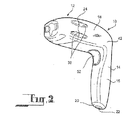
本発明の第一の局面に従って、アダプター12を有する多目的画像化装置10がある。多目的画像化装置10は、図1〜5を参照して、ここで記載される。
In accordance with a first aspect of the present invention, there is a
多目的画像化装置10は、本体14からなる。図示される実施形態において、本体14は、「L」のような形状である。本体14の短い方のセクション16は、ハンドルとして働き、そして本体14の長い方のセクション18と比較して、幅Wだけ狭い。本体14の第一の端部20は、そこに配置されるI/Oポート22を有する。本体14の第二の端部24は、アダプター12を受容し、そしてしっかりと保持するように構成される。
The
第二の端部24は、凹面26を有する。レンズ28が、凹面26の周りで中心を合わせて配置され、そしてこの面から突出する。凹面26にはまた、インターフェース接点30が位置する。図示される実施形態において、インターフェース接点30は、多目的画像化装置10が、物体の映像が撮影され得るような配向(本明細書中以下で、「通常配向」と称される)にある場合に、レンズ28の下方に位置する。凹面26に隣接して、内側壁32a、32bにおいて、溝34a、34bが位置する。
The
レンズ28は、デジタルカメラ36の一部を形成する。デジタルカメラ36は、本体14の長い方のセクション18に収容される。任意のデジタルカメラが使用され得るが、以下:
・1秒間あたり15フレーム未満のフレーム速度;および/または
・網膜像上の30μmスポットより大きい解像度;および/または
・1ルクス未満の感度
を有するデジタルカメラは、診断目的に適切な画像を生じ得ないかもしれない。
The
A frame rate of less than 15 frames per second; and / or a resolution greater than a 30 μm spot on the retinal image; and / or a digital camera with a sensitivity of less than 1 lux may not produce an image suitable for diagnostic purposes. It may be.
第二の端部24はまた、側部40aおよび側部40bに位置するグリップ38を有する。グリップ38の機能は、以下に提供される多目的画像化装置10の使用の例から容易に明らかであり、従って、ここではさらに議論されない。
短い方のセクション16および長い方のセクション18の接合部42に、複数のユーザコントロール44が位置する。ユーザコントロール44は、接合部42の、通常配向の間にユーザに面する表面に位置付けられる。
A plurality of
ユーザコントロール44は、2つのLED46a、46b、2つの押しボタン48a、48b、および2つのゲインコントローラー50a、50bを備える。ユーザコントロール44は、インターフェース接点30に電子的に接続され、そしてユーザが、多目的画像化装置10に取り付けられたアダプター12の光学的作動および/または電気的作動を調節することを可能にする。このことは、以下でさらに詳細に記載される。
The
また、接合部42においてであるが、接合部42の、ユーザコントロール44とは反対側の表面に、画像捕捉ボタン52が位置する。画像捕捉ボタン52は、デジタルカメラ36と制御通信する。画像捕捉ボタン52が押される場合、デジタルカメラ36は、画像を記録し、この画像は、次に、焦点を合わせられ、そしてメモリ(図示せず)に保存される。
In addition, the
このメモリは、任意の形態を採り得るが、記載される実施形態において、このメモリは、CompactFlashTMカード(例えば、Canon,Inc.から入手可能なもの)、SonyTMメモリースティック(Sony Corporation of Americaから入手可能)、またはSecure Digital Memoryカード(例えば、Hewlett−Packard Companyから入手可能なもの)であり得る。選択されるメモリの実際の形態にかかわらず、メモリは、I/Oポート22内に受信され、そして保持される。メモリは、必要な際に(例えば、メモリがデジタル画像でいっぱいである場合、またはメモリに保存された画像がさらなる処理のために別のデバイスに移動される場合)、I/Oポート22から取り出され得る。
The memory may take any form, but in the described embodiment, the memory is a CompactFlash ™ card (eg, available from Canon, Inc.), Sony ™ Memory Stick (obtained from Sony Corporation of America). Possible), or a Secure Digital Memory card (eg, available from the Hewlett-Packard Company). Regardless of the actual form of memory selected, the memory is received and held in the I /
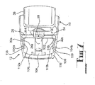
アダプター12は、図5〜7に示されるような一般的構造を有し、そしてこの構造が、ここで議論される。各アダプター12の光学構成要素、電子工学構成要素、および他のあつらえた構成要素が、具体的に記載される。
The
図5に示されるように、各アダプター12は、本体100からなる。本体100は、形状が実質的に矩形であり、そして後面102、2つの側面104a、104b、および前面106を有する。
As shown in FIG. 5, each
後面102は、凹面26と等しい大きさおよび形状のものである。開口部108が、後面102の周りで中心をあわせて配置される。開口部108は、アダプター12を通って延び、その結果、開口部108もまた、前面106の周りで中心を合わせて位置される。開口部108に隣接して、インターフェース接点110が位置する。
The
後面102に隣接して、2つのスナップクリップ112a、112bが位置する。スナップクリップ112aは、側面104aから延び、一方で、スナップクリップ112bは、側面104bから延びる。各スナップクリップ112は、内部凹部114を有し、この凹部は、適切な圧力が付与される場合に、スナップクリップ112が開口部108の方へと曲がり得るように配置される。スナップクリップ112a、112bは、それぞれ、溝34a、34b内に解放可能に保持されるように適合される。
Adjacent to the
前面106を囲み、そして側面104の一部に沿って後面102の方へと、ゴム製オーバーモールディング116が延びる。ゴム製オーバーモールディング116は、各スナップクリップ112の部分118の部分を覆う。フィンガーグリップ120が、ゴム製オーバーモールディング116の外面122内に、部分118に実質的に隣接する位置で形成される。
A
スナップクリップ112が溝34内で解放可能に保持される場合、以下の状況が存在する:
・開口部108が、デジタルカメラ36の光軸Xと整列し、その結果、光軸Xの少なくとも一部が、アダプター12の残りの部分によって妨害されない;
・インターフェース接点110が、インターフェース接点30との接続を形成する;そして
・ゴム製オーバーモールディング116の外面122が、多目的画像化装置10の外面と同一面になり、これによって、アダプター12が画像化装置10と一体的であるように見せる。
When the snap clip 112 is releasably held in the groove 34, the following situation exists:
The
The
各アダプター12の光学的構成要素、電子的構成要素、および他のあつらえの構成要素が、ここで記載される。
The optical components, electronic components, and other custom components of each
図8は、スリットランプアダプター150の光学および電子光学を示す。
FIG. 8 shows the optics and electro-optics of the
スリットランプアダプター150の前面106から、2つのスリットランプデバイス152a、152bが突出する。両方のスリットランプデバイス152は、角度が付けられており、その結果、多目的携帯型画像化装置10が患者の左目の前で通常配向に保持される場合に、スリットランプデバイス152aがスリットランプとして作動可能であり、一方で、患者の右目の前で通常配向に保持される場合に、スリットランプデバイス152bがスリットランプとして作動可能である。この多目的画像化装置の操作者は、スリットランプ152aと152bとのいずれが、以下にさらに詳細に記載される様式で作動可能であるかを選択し得る。
Two slit lamp devices 152 a and 152 b protrude from the
各スリットランプデバイス152a、152bは、1対の隣接する固体ランプ154a、154b、および付随する光学156を備える。固体ランプ154a、154bは、白色LEDであり、そして一緒に組み合わせられて、光源158を形成する。LEDの使用は、これらのより低い電力要求および熱損失、ならびにこれらの内部に集束する光に起因して、小さい電球より好ましいが、本発明に対して必須ではない。
Each slit lamp device 152a, 152b includes a pair of adjacent
光源158は、2つの重なる光の円錐160a、160bを発生させる。重なる光の円錐160a、160bは、組和せられて、初期の細長いビーム162を形成する。初期の細長いビーム162は、構造体164aと164bとの間に形成された狭いスリット166を通過するにつれて、これらの構造体によって横方向にトリミングされる。
The
狭いスリット166の幅は、構造体164a、164bのいずれか、または両方の位置を変化させることによって、調節され得る。狭いスリット166がより狭くされる場合、眼の前部の光学セクションが見られる。狭いスリット166が少し広くされる場合、透明組織のブロックが照射される。狭いスリット166は、約0.08mmの幅であることが好ましい。
The width of the
狭いスリット166から出るビームは、中間ビーム168と称される。次いで、中間ビーム168は、均一な半円形断面のプリズムレンズ172の平坦な面170に方向付けられ、平坦な面170は、中間ビーム168に対して直交する。プリズムレンズ172は、中間ビーム168を、狭いスリット166および細長いビーム162と整列するように集束させる。プリズムレンズ172はまた、中間ビーム168を長手軸方向にトリミングし、光の円錐160a、160bの重なりによって形成されるセグメントに対するセグメントに戻す。
The beam exiting the
プリズムレンズ172を通過する光のビームは、光の狭いビーム174である。患者の眼の角膜の方へと集束されるものは、光のこの狭いビーム174である。
The light beam passing through the
光学176は、開口部108内にしっかりと受容されて、デジタルカメラ36が、眼の構造体による光の狭いビーム174の反射の画像を捕捉することを容易にする。さらなる光源178がまた、前面106に配置される。さらなる光源178は、角膜のバックグラウンド照射を提供し、これによって、眼の高品質の画像を提供することを補助する。
The optics 176 is securely received within the
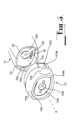
図9は、赤色反射アダプター200の光学および電子光学を示す。
FIG. 9 shows the optics and electro-optics of the red
このアダプターにおいて、ビームスプリッター202が、開口部108内に、後面102に実質的に隣接する位置で受容される。光源204(白色LEDの形態)が、凹部206内で、ビームスプリッター202の上方に配置される。光源204の、光軸Xに対する整列は、これらの間の角度が、ビームスプリッター202の位置で測定される場合に、90°であるような整列である。
In this adapter, a
この構成において、光源204から発光される光は、ビームスプリッター202に方向付けられる(凹部206が、任意の分散光を吸収する)。ビームスプリッター202と接触する際に、光は、いくらかの光が、光軸Xに沿って90°反射されて、患者の眼に直接向かうように、分割される。
In this configuration, the light emitted from the
ビームスプリッター202を通過する光は、記録されるべき画像の一体性を妨害する、所望でない反射を引き起こし得るので、さらなる開口部208が、赤色反射アダプター200内に形成される。さらなる開口部208は、開口部108を横断する位置で、本体100を通って延びる。さらなる開口部208は、光源204と同一面内であり、そして光源204と実質的に同じ大きさおよび形状である。この様式で、ビームスプリッター202を通過する光は、この光が赤色反射アダプター200の本体100に入るまで、さらなる開口部208に沿って方向付けられる。
Because light passing through the
図10は、蛍光アダプター250の光学および電子光学を示す。
FIG. 10 shows the optics and electro-optics of the
蛍光アダプター250の光学および電子光学は、2つの青色ダイオード252a、252bと、黄色フィルター254とを備える。青色ダイオード252a、252bは、蛍光アダプター250の前面106から突出する。黄色フィルター254は、光軸Xの経路中の開口108内に受容される。
The optical and electronic optics of the
この2つの青色ダイオード252a、252bは、画像化されるべき眼を一様に照射するために使用される。黄色フィルター254は、デジタルカメラ36に向かうあらゆる反射光を取り除くように作動する。
The two
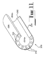
図11は、涙液膜アダプター300の光学および電子光学を示す。
FIG. 11 shows the optics and electro-optics of the
開口端304a、304bを有する中空で透明のシリンダー302が、開口108内に固定的に受容される。このシリンダー302は、開口108の寸法と同じ寸法であり、その結果、端部304aは、前面106と揃い、端部304bは、背面102と揃う。
A hollow,
反射フィルムのシート306が、シリンダー302の外壁308を取り囲む。反射フィルム306とシリンダー302との組み合わせは、鏡効果を生じる。
A sheet of
複数のLED 316が、シリンダー302の開放端304aに位置する。LED 316は、端部304aの周辺に沿って等距離に間隔を開けている。LED 316の数(従って、間隔)は、均一な光源を生じるようでなければならない。
A plurality of
図12は、眼底(fundus)アダプター350の光学および電子光学を示す。 FIG. 12 shows the optics and electro-optics of the fundus adapter 350.
このアダプターにおいて、ビームスプリッター352および二重凸面レンズ354が、開口108内に受容される。ビームスプリッター352は、実質的に隣接する背面102である。二重凸面レンズ354は、実質的に隣接する前面106である。
In this adapter, a beam splitter 352 and a double
光源356(白色LEDの形態である)が、凹部358中のビームスプリッター352の上に位置する。二重凸面レンズ354に対する光源356の配置は、その間の角度が、ビームスプリッター352の位置の尺度として、90°であるようになっている。
A light source 356 (in the form of a white LED) is located above the beam splitter 352 in the recess 358. The arrangement of the
この構成において、光源356から放射される光は、ビームスプリッター352(あらゆる分散光を吸収する凹部358)に向けられる。ビームスプリッター352と接触すると、その光は、いくらかの光が二重凸面レンズ354へ向かって90°反射するように、分裂する。その後、その光は、二重凸面レンズ354により集束され、その結果、その光は、虹彩および水晶体を貫通して、患者の眼の眼底を表示し得る。残りの光は、ビームスプリッター352を通る。
In this configuration, light emitted from the
ビームスプリッター352を通る光が、記録されるべき眼底の画像の強度に干渉する望ましくない反射を引き起こし得るので、さらなる開口360が、眼底アダプター350内に形成される。さらなる開口360が、開口108に対して横切る位置にある本体100を通って延びる。さらなる開口360が、光源356と同じ面にあり、そして光源356と実質的に同じ大きさおよび形状である。この様式で、ビームスプリッター352を通る光は、その光が眼底アダプター350の本体100を出るまで、さらなる開口360に沿って方向付けられる。
An additional aperture 360 is formed in the fundus adapter 350 because light through the beam splitter 352 can cause undesirable reflections that interfere with the intensity of the fundus image to be recorded. A further opening 360 extends through the
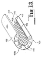
図13は、nibutアダプター400の光学および電子光学を示す。
FIG. 13 shows the optics and electro-optics of the
開放端404a、404bを有する中空で透明のシリンダー402が、開口108内に固定的に受容される。このシリンダー402は、開口108と同じ寸法であり、その結果、端部404aは、前面106と揃い、端部404bは、背面102と揃う。
A hollow,
反射フィルム406のシートが、シリンダー402の外壁408を囲む。反射フィルム406とシリンダー402との組み合わせは、鏡効果を生じる。
A sheet of
透明シート410は、シリンダー402の内壁412を囲む。透明シート410は、そのシート上に印刷された格子パターン414を有する。
The transparent sheet 410 surrounds the
複数のLED416が、シリンダー402の開放端404bに位置する。LED 416は、端部404bの周辺に沿って等距離に間隔を開けている。LED 416の数(従って、間隔)は、均一な光源を生じるようでなければならない。
A plurality of
図14は、歯科用アダプター450の平面図を示す。
FIG. 14 shows a plan view of the
歯科用アダプター450は、2つの光源452a、452bと、2つの角度の付いた開口454a、454bとを備える。光源452aおよび452bは、開口108に対して反対の位置で、前面106から突出する。角度の付いた開口454a、454bは、これもまた開口108に対して反対の位置で、光源452a、452bの位置と整列して、歯科用アダプター450の本体100を通って延びる。従って、角度の付いた開口454aは、光源452aに対応し、角度の付いた454bは、光源452bに対応する。
The
角度の付いた454a、454bは、各々、歯科鏡456を受容するように各々適合される。開口454a、454bの大きさは、歯科鏡456が、中に堅く保持されるようになっているが、歯科鏡456が、滑動可能に調節された位置を有し得る程度である。
Angled 454a, 454b are each adapted to receive a
示される実施形態において、前面106に対する角度の付いた454a、454bの角度は、83°である。しかし、角度の付いた454a、454bの角度は、そのような開口454と、その個別の光源452との間の距離によって、決定される。精巧にするために、その角度は、光源452が、対応する角度の付いた開口454内に保持された歯科鏡456の鏡位置458に光を向けるようであるべきである。
In the embodiment shown, the angle of angled 454a, 454b relative to the
図15aおよび15bは、耳鏡アダプター500の光学および電子光学を示す。 FIGS. 15 a and 15 b show the optics and electro-optics of the otoscope adapter 500.
耳鏡アダプター500は、レンズ502、光源504、集束手段506および耳栓508を備える。
The otoscope adapter 500 includes a
レンズ502は、前面106に実質的に近接するが前面106から間隔を空けた位置にて、開口108内に固定的に受容される。光源504(LEDの形態)が、レンズ502と前面106との間の開口108の領域内に位置する。光源504の方向付けは、下記に記載される。
The
示される実施形態において、集束手段506は、レンズスライダー510の形態を採る。レンズスライダー510の回転は、ビデオカメラ36とレンズ502との間の距離を調節し、それによって、レンズ502の焦点を調節する。
In the embodiment shown, the focusing means 506 takes the form of a
耳栓508は、耳鏡アダプターの前面106上に受容されるように調節される。耳栓508は、端部512に小さい開口を有する標準的な携帯型耳鏡において使用される耳栓と同一である。
光源504は、開口108の周辺に向かって配置され、そしてその光源からの光が、端部512の小さい開口部を通って出るように方向付けられる。
The
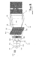
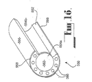
図16は、皮膚科用アダプター550の光学および電子光学を示す。
FIG. 16 shows the optics and electro-optics of
開放端554a、554bを有する中空で透明のシリンダー552が、開口108内に固定的に受容される。このシリンダー552は、開口108と同じ寸法であり、その結果、端部554aは、前面106と揃い、端部554bは、背面102と揃う。
A hollow,
反射フィルム556のシートが、シリンダー552の外壁558を囲む。反射フィルム556とシリンダー552との組み合わせは、鏡効果を生じる。
A sheet of
複数のLED560が、シリンダー552の開放端554aに位置する。LED 560は、端部554aの周辺に沿って等距離に間隔を開けている。LED 560の数(従って、間隔)は、均一な光源を生じるようでなければならない。
A plurality of
シリンダー552の開放端554aにまた、拡大レンズ562も位置する。示される実施形態において、拡大レンズ562は、画像化されるべき領域を10倍拡大する。しかし、種々の拡大比の拡大レンズ562が、使用され得る。
A magnifying
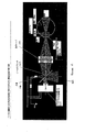
本発明の第2の局面に従って、同様の数字が同様の部分を参照する場合、多目的画像化システム600が存在する。この多目的画像化システム600は、本発明の第1局面に記載されるような、多目的画像化装置10および各アダプター12、ならびに処理ユニット602を備える。上記の構成要素10、12、602の各々は、ケース606の予め形成された区画604内に受容される。これにより、整然としかつ効率的な様式で、多目的画像化システム600の構成要素がある位置から別の位置へと輸送されるのが可能になる。
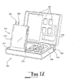
In accordance with the second aspect of the present invention,
図17に示される本発明の第2の局面の実施形態において、多目的画像化装置10が、上記の装置から改変されている。I/Oポート22内に受容されるメモリの代わりに、I/Oポート22が、USBケーブル608の一端を受容するように適合される。USBケーブル608のもう一方の端部は、処理ユニット602に接続される。
In the embodiment of the second aspect of the present invention shown in FIG. 17, the
USBケーブル608を受容するように多目的画像化装置10を改変することは、重要ではあるが必須というわけではない、設計の利点である。特に、USB接続により、データを、多目的画像化装置10から高移動速度で処理ユニット602へと移動することが可能である。さらに、USB接続により、多目的画像化装置10が、処理ユニット602から電力を引き出し、それによって別個の電源の必要性を打ち消すことが可能になる。
Modifying
示される実施形態において、処理ユニット602は、タブレットPC 610の形態を採る。タブレットPC 610は、回転点612の周囲を回転することによって、その予め形成された区画604から上昇するように適合される。
In the embodiment shown, the
タブレットPC 610の選択は、ノートブックまたはデスクトップコンピューターに優先して、このシステムに対してさらなる設計的利点を提供する。特に、タブレットPC 610は、頑丈であり、使用し易く、データは、キーボートではなくスタイレット614を通して入力可能である。同時に、タブレットPCは、音声入力命令のために準備される。現在のタブレットPCのハードウェア構成もまた、意図される目的のために十分である。タブレットPCの低重量局面および大きな高解像度スクリーンサイズもまた、別個の利点である。
The choice of
ケース606は、組み込み型電力変圧器616を有する。電力変圧器616は、ケーブル618を介してタブレットPC 608に電力を提供する。使用を容易にするために、電力変圧器616は、ケース606の側壁622中に組み込まれた電力接続620を有する。示される実施形態における電力接続620は、標準的な3ピン電力ケーブルを受容するように適合される(示されず)。電力接続620はまた、電力変圧器616をオンまたはオフにするための、電力スイッチ624を備える。
タブレットPC608に電力を提供することに加えて、電力変圧器616が、ケース606中に組み込まれるバッテリー(示さず)に接続される。このバッテリーは、必要な場合タブレットPC608にさらなる電力を提供する。
In addition to providing power to the tablet PC 608, a power transformer 616 is connected to a battery (not shown) built into the
多目的画像化装置10の使用が、上記の多目的画像化システム600の文脈において記載される。
The use of
ケース606が開かれて、多目的画像化装置10、アダプター12およびタブレットPC610を明らかにする。次いで、タブレットPC610は、操作者が使用のために快適であると見出す位置にこれが達するまで、旋回点612の周りを旋回される。その後、多目的画像化装置10は、USBケーブル608を介してタブレットPC610に接続される。
上に述べられるように、USBケーブル608の使用は、多目的画像化装置10に電力を提供する。タブレットPC610が、1つの充填されたバッテリーを有し、外部電力源から電力を引き込んでいない場合、多目的画像化システム600は、1時間から2時間の間の時間の間作動可能であると予期される。より長い時間作動可能である多目的画像化システム600のために、主電源または電源の他の形態への接続を行い、またはケース606の一部を形成するバッテリーを利用することが、推薦される。前者の推薦に関して、これは、標準的3ピン電力ケーブル(示さず)の一端を電力接続620中に挿入し、そしてもう一方の端を主電源または代替電源中に挿入することにより達成され得る。未だ接続されていない場合、次いで、ケーブル618は、タブレットPC610の電力接続中に受容されなければならず、電力スイッチ624が、オンに設定される。
As described above, use of the USB cable 608 provides power to the
ここで、上に記載された順序で、アダプター12の各々についての考察がなされる。しかし、これは、例示的な目的のみのために行なわれることが、当業者によって理解されるべきである。
Here, consideration is given to each of the
スリットランプアダプター150が、スナップクリップ112が溝34に係合するまでアダプター12に力をかけることにより、多目的画像化装置10に接続される。この方法は、図5および6で例示される。
The
次いで、多目的画像化装置10が、スリットランプデバイス152が患者の目の前に直接保持されるレベルおよび位置に持ち上げられる。操作者の快適さを促すために、操作者はグリップ38のまわりで多目的デジタル画像化装置10をつかみ得る。
The
スリットランプデバイス152が、患者の右目の前に直接保持される場合、操作者は、押しボタン48aを押す。このアダプター12の文脈において、押しボタン48aを押すことによりスリットランプデバイス152bおよびさらなる光源178は作動される。これはまた、LED46aを点灯させ、それにより操作者に、多目的画像化装置10が患者の右目を画像化するように設定されていることを知らせる。
When the slit lamp device 152 is held directly in front of the patient's right eye, the operator presses the push button 48a. In the context of this
スリットランプデバイス152bの作動は、上で与えられた光学的配置の記載に従ってそこから伸びる光の細いビーム174を生じる。次いで、多目的画像化装置10の操作は、通常のスリットランプが操作されていた場合そうであるのと同じ様式で続く。
The operation of the slit lamp device 152b produces a
画像捕捉ボタン52を押すことにより、デジタルカメラ36に、目の構造によって光の細いビーム174の反射の像を捕捉させ、この像は、多目的画像化装置10から直接見られる実質的なスリット画像そのものである。次いで、この画像が、保存および/またはさらなる処理のために、USBケーブル608を介してタブレットPC610にダウンロードされる。
Pressing the
操作者が、例えば患者の虹彩が青もしくは茶色または他のより暗い色である状態で、光源158により作り出される光の明るさを変える必要がある場合、これは、ゲインコントローラー50aの適切な操作により達成され得る。操作者がさらなる光源178により作製される光の明るさを変え、それによりバックルラウンド照射のレベルを調節する必要がある場合、これは、ゲインコントローラー50bの適切な操作により達成され得る。
If the operator needs to change the brightness of the light produced by the
スリットランプデバイス152が、患者の左目の前に直接保持される場合、操作者は、押しボタン48bを押す。このアダプター12の文脈において、押しボタン48bを押すことにより、スリットランプデバイス152aおよびさらなる光源178を作動させる。これはまた、LED46bを点灯させ、それにより操作者に、多目的画像化装置10が患者の左目を画像化するよう設定されていることを知らせる。
When the slit lamp device 152 is held directly in front of the patient's left eye, the operator presses the push button 48b. In the context of this
スリットランプデバイス152aの作動は、上で与えられた光学的配置の記載に従ってそこから伸びる光の細いビーム174を生じる。次いで、多目的画像化装置10の操作は、通常のスリットランプが操作されていた場合そうであるのと同じ様式で続く。
The operation of the slit lamp device 152a produces a
画像捕捉ボタン52を押すことにより、デジタルカメラ36に、目の構造によって光の細いビーム174の反射の像を捕捉させ、この像は、多目的画像化装置10から直接見られる実質的なスリット画像そのものである。次いで、この画像が、保存および/またはさらなる処理のために、USBケーブル608を介してタブレットPC610にダウンロードされる。
Pressing the
操作者が、例えば患者の虹彩が青もしくは茶色または他のより暗い色である状態で、光源158により作り出される光の明るさを変える必要がある場合、これは、ゲインコントローラー50bの適切な操作により達成され得る。操作者がさらなる光源178により作製される光の明るさを変え、それによりバックルラウンド照射のレベルを調節する必要がある場合、これは、ゲインコントローラー50aの適切な操作により達成され得る。
If the operator needs to change the brightness of the light produced by the
ただ1つのスリットランプデバイス152が、常に操作され得ることが、注目されるべきである。従って、スリットランプデバイス152bが作動される場合、押しボタン48aを押すことによりスリットデバイス152bを作動しないように操作される。同様に、スリットランプデバイス152bが作動される場合、押しボタン48bを押すことによりスリットデバイス152aを作動しないように操作される。次いで、LED46a、46bのただ1つが、多目的画像化装置10の新しい操作様式に適切なように点灯される。
It should be noted that only one slit lamp device 152 can be operated at any time. Therefore, when the slit lamp device 152b is activated, the slit device 152b is operated so as not to be activated by pressing the push button 48a. Similarly, when the slit lamp device 152b is activated, it is operated so as not to activate the slit device 152a by pressing the push button 48b. Then, only one of the LEDs 46a, 46b is lit as appropriate for the new mode of operation of the
次いで、スリットランプアダプター150の除去が、フィンガークリップ120に圧力を加え、その結果スナップクリップ112が開口108に向かってその各々の内部の凹部114中に移動することにより、達成される。この移動は、スナップクリップ112を溝34から脱係合させる。次いで、スリットランプアダプター150が、容易に除去され得る。
Removal of the
スリットランプアダプター150が除去されると、赤色反射アダプター200が、多目的画像化装置10に接続され得る。赤色反射アダプター200の接続が、スリットランプアダプター200を接続させるための上記のような同じ手順の後に続く。
When the
一旦接続されると、次いで、多目的画像化装置10は、デジタルカメラ36の光軸に沿って移動する光が患者の目に向けられるようなレベルおよび位置に持ち上げられる。
Once connected, the
押しボタン48bを押すことにより、光源204の作動がトグルされる。光源204が作動される場合、LED46bが点灯される。スリットランプアダプター150と一緒に、光源204の明るさが、ゲインコントローラー50bの適切な操作によって制御され得る。
By pushing the push button 48b, the operation of the
次いで、多目的画像化装置10の操作が、通常の赤色反射生成デバイスが操作される場合そうであるのと同じ様式で続く。画像捕捉ボタン52を押すことにより、デジタルカメラ36に赤色反射画像を捕捉させる。次いで、この画像が、保存および/またはさらなる処理のためにUSBケーブル608を介してタブレットPC610にダウンロードされる。
The operation of the
目の背部から赤色反射画像を得るために、光軸Xに沿って移動する光が、中心光軸から離れた患者の目に向けられることが、推薦される。理想的には、このような光の方向についての角度は、5°から20°の間である。 In order to obtain a red reflection image from the back of the eye, it is recommended that light traveling along the optical axis X be directed to the patient's eyes away from the central optical axis. Ideally, the angle for such light direction is between 5 ° and 20 °.
一旦全ての所望される赤色反射画像が捕捉されると、赤色反射アダプター200が、蛍光アダプター250で置換される。アダプター12を取り除き、かつ別のアダプター12を接続させる手順は、上に記載されており、再び繰り返されない。
Once all desired red reflection images have been captured, the
この構成での多目的画像化装置10の使用の前に、蛍光色素が、患者の眼内に投入される。
Prior to use of the
次いで、多目的画像化装置10が、作動される場合、青色ダイオード252が、画像化される患者の目中に投影される蛍光色素を照射するようなレベルおよび状態に、持ち上げられる。
Then, when the
押しボタン48bを押すことにより、青色ダイオード252の作動がトグルされる。青色ダイオード252が作動される場合、LED46bが点灯される。スリットランプアダプター150と一緒に、青色ダイオード252の明るさが、ゲインコントローラー50bの適切な操作によって制御され得る。
By pushing the push button 48b, the operation of the blue diode 252 is toggled. When the blue diode 252 is activated, the LED 46b is lit. Along with the
次いで、多目的画像化装置10の操作が、通常の蛍光画像化デバイスが操作される場合そうであるのと同じ様式で続く。画像捕捉ボタン52を押すことにより、デジタルカメラ36に色素の蛍光の画像を捕捉させる。黄色フィルター254の配置は、画像に、その画像に対してわずかに黄色を帯びさせるが、上に記載されるように、これは、あらゆる反射光を遮断するのを助ける。次いで、この画像が、保存および/またはさらなる処理のためにUSBケーブル608を介してタブレットPC610にダウンロードされる。
The operation of
一旦全ての所望される蛍光画像が捕捉されると、蛍光アダプター250が、涙液膜アダプター300で置換される。
Once all the desired fluorescent images have been captured, the
多目的画像化装置10に接続される涙液膜アダプター300を有する多目的画像化装置10が、デジタルカメラ36の光軸Xに沿って移動する光が患者の目に向けられるようなレベルおよび位置に持ち上げられる。
The
押しボタン48bを押すことにより、LED316の作動がトグルされる。LED316が作動される場合、LED46bが点灯される。スリットランプアダプター150と一緒に、LED316の明るさが、ゲインコントローラー50bの適切な操作によって制御され得る。
By pushing the push button 48b, the operation of the
次いで、多目的画像化装置10の操作が、通常の涙液膜分析器が操作される場合そうであるのと同じ様式で続く。画像捕捉ボタン52を押すことにより、デジタルカメラ36に涙液膜の画像を捕捉させる。次いで、この画像が、保存および/またはさらなる処理のためにUSBケーブル608を介してタブレットPC610にダウンロードされる。
The operation of the
一旦、全ての必要とされる涙液膜画像が、捕捉されると、涙液膜アダプター300が、眼底アダプター350と置換される。
Once all the required tear film images have been captured, the
次いで、多目的画像化装置10を、デジタルカメラ36の光軸Xに沿って進む光が、患者の眼に向けられるレベルおよび位置に上昇させる。
The
押しボタン48bを押すことによって、光源356の作動をトグルする。光源356が作動する場合、LED46bが光る。スリットランプアダプター150とともに、光源356の明るさは、ゲインコントローラー50bの適切な操作によって制御され得る。
By pushing the push button 48b, the operation of the
次いで、多目的画像化装置10の操作を、通常の眼底カメラが操作される様式と同じ様式で進める。画像捕捉ボタン52を押すことによって、デジタルカメラ36が、眼底の画像を捕捉する。次いで、この画像を、保存および/またはさらなる処理のためにUSBケーブル608を介してタブレットPC610にダウンロードする。
Then, the operation of the
一旦、眼の眼底の全ての必要とされる画像が、捕捉されると、眼底アダプター350は、nibutアダプター400で置換される。
Once all the required images of the fundus of the eye have been captured, the fundus adapter 350 is replaced with the
多目的画像化装置10を、デジタルカメラ36の光軸Xに沿って進む光が、患者の眼に向けられるレベルおよび位置に上昇させる。
The
押しボタン48bを押すことによって、LED416の作動をトグルする。LED416が作動する場合、LED46bが光る。スリットランプアダプター150とともに、LED416の明るさは、ゲインコントローラー50bの適切な操作によって制御され得る。
By pushing the push button 48b, the operation of the
LED416の作動によって、一連の円形格子配置が、眼に形成される。次いで、この格子が、眼の異常または他の目的の点の位置に対する参照として使用され得る。
By actuation of the
画像捕捉ボタン52を押すことによって、デジタルカメラ36が、円形格子配置を用いて完全な眼の画像を捕捉する。次いで、画像を、保存および/またはさらなる処理のためにUSBケーブル608を介してタブレットPC610にダウンロードする。
By pressing the
一旦、nibutアダプター400に必要とされる全ての画像が、捕捉されると、nibutアダプター400は、歯科アダプター450で置換される。
Once all the images required for the
歯科アダプター450を取り付けた後に、滅菌歯科鏡456を、最も適切な操作および活動が実行されるように、角度の付いた開口454aまたは454bのいずれかに挿入される。
After attaching
押しボタン48bを押すことによって、そこに受容される歯科鏡456を有する角度の付いた開口454と対応する光源452の作動をトグルする。光源452が作動する場合、LED46bが光る。スリットランプアダプター150とともに、光源452の明るさは、ゲインコントローラー50bの適切な操作によって制御され得る。
Pressing push button 48b toggles the actuation of light source 452 corresponding to angled opening 454 having
光源452が作動する場合、光源452は、光を歯科鏡456の鏡部分(ここで、光が反射する)上に光を向ける。次いで、操作者が、この反射した光を使用して、それ以外では容易に見ることができない口の領域を見ることができる。図14から明らかではないが、歯科鏡456の鏡部分は、デジタルカメラ36の光軸X内にあり、操作者が、画像捕捉ボタン52を押したときに、歯科鏡456を使用して見える口の任意の領域の画像を捕捉し得る。次いで、捕捉された画像を、保存および/またはさらなる処理のためにUSBケーブル608を介してタブレットPCにダウンロードする。
When the light source 452 is activated, the light source 452 directs the light onto the mirror portion of the dental mirror 456 (where the light is reflected). The operator can then use this reflected light to see areas of the mouth that are otherwise not easily visible. Although not apparent from FIG. 14, the mirror portion of the
一旦、全ての歯科画像が捕捉されると、歯科アダプター450は、耳鏡(otoloscope)アダプター500で置換される。歯科鏡456はまた、歯科アダプターから取り外され、後の使用のために滅菌される。
Once all dental images have been captured, the
耳鏡アダプター500を取り付けた後に、耳栓508が、その前面106に取り付けられる。次いで、耳鏡アダプター500は、耳栓508が患者の耳内に挿入されるように、位置付けられる。
After attaching the otoscope adapter 500, the
押しボタン48bを押すことによって、LED504の作動をトグルする。LED504が作動する場合、LED46bが光る。スリットランプアダプター150とともに、LED504の明るさは、ゲインコントローラー50bの適切な操作によって制御され得る。
By pushing the push button 48b, the operation of the
LED504が作動する場合、LED504は、端部512における小さな開口部を通って患者の耳内に光を向ける。耳栓508の患者の耳内への挿入の深さが患者間で変化するので、操作者は、適切な様式でレンズスライダー510を操作することによって、デジタルカメラ36に提供される画像を集束し得る。
When the
画像捕捉ボタン52を押すことによって、患者の耳の画像は、デジタルカメラ36によって捕捉される。次いで、捕捉された画像を、保存および/またはさらなる処理のためにUSBケーブル608を介してタブレットPC610にダウンロードする。
By pressing the
一旦、患者の耳の全ての必要とされる画像が捕捉されると、耳鏡アダプター500は、皮膚科学アダプター550で置換される。耳栓508は、耳鏡500から取り除かれ、廃棄される。
Once all the required images of the patient's ear have been captured, the otoscope adapter 500 is replaced with a
次いで、多目的画像化装置10は、皮膚科学アダプター550の前面106が画像化されることが求められる患者の領域に当接するように、位置付けられる。
The
押しボタン48bを押すことによって、LED560の作動をトグルする。LED560が作動する場合、LED46bが光る。スリットランプアダプター150とともに、LED560の明るさは、ゲインコントローラー50bの適切な操作によって制御され得る。
By pushing the push button 48b, the operation of the
その後、操作者は、患者の皮膚に沿って、多目的画像化装置10を自由に移動させる。画像捕捉ボタン52を押すことによって、デジタルカメラ36が、拡大レンズ562に起因して、10倍の拡大で、皮膚の画像を捕捉する。次いで、画像を、保存および/またはさらなる処理のためにUSBケーブル608を介してタブレットPC610にダウンロードする。
Thereafter, the operator freely moves the
全ての皮膚科学画像が捕捉されると、皮膚科学アダプター550の前面が、多目的画像化装置10から取り除かれる前に、任意の夾雑物を除去するために、拭かれる。次いで、多目的画像化装置10およびアダプター12を、それぞれの予め成型された区画604内に置換する。
Once all dermatological images have been captured, the front surface of
ユーザコントロール44が、右利き操作者のために便利であるように、記載されていることが、上記記載から注記されるべきである。しかし、ユーザコントロール44は、例えば、タブレットPC610からアップロードされるソフトウェアにおける変化によって、左利き操作者に適応させるように逆転され得る。さらに、スリットランプアダプター150が取り付けられた多目的画像化装置10を除いて、使用されるセットのコントロールの選択は、画像化される眼のタブレットPC610に表示され得る。精巧にするために、押しボタン48aおよびゲインコントローラー50aの使用は、患者の右眼が画像化されていることをタブレットPC610に表示し、一方、押しボタン48bおよびゲインコントローラー50bの使用は、患者の左眼が画像化されていることをタブレットPC610に表示する。
It should be noted from the above description that the user controls 44 are described so as to be convenient for right-handed operators. However, the user controls 44 can be reversed to accommodate left-handed operators, for example, by changes in software uploaded from the
スリットランプアダプター150の代替の配置において、スリットランプデバイス152は、多目的装置10の通常の操作に対して、水平および/または垂直の角度調節を可能にする様式で装着され得る。
In an alternative arrangement of the
蛍光アダプター250の代替の配置において、青色ダイオード252a、252bは、代替の光源および青色フィルター配置で置換され得る。さらに、蛍光アダプター250は、より多いまたはより少ない青色ダイオード252で構成され得る。
In an alternative arrangement of the
第2の実施形態の代替の配置において、ユーザコントロール44に加えて、声の指令が、操作者によって、タブレットPC610に与えられ得、タブレットPC610は、このような指令(例えば、画像の捕捉など)を実行するように操作可能である。ケース608はまた、操作の間、患者の頭の正確な位置付けを可能にするために、その中に組み込まれたヘッドセット装置を有し得る。さらに、IrDAキーボードが、ケース606の蓋内に構築され得る。
In an alternative arrangement of the second embodiment, in addition to
第2の実施形態のなおさらなる代替の配置において、USB接続は、FirewireTM接続で置換され得る。あるいは、物理的接続の全ての形態は、省略され得、多目的処理装置10は、無線手段を介して、タブレットPC610と連絡し得る。
In yet a further alternative arrangement of the second embodiment, the USB connection can be replaced with a Firewire ™ connection. Alternatively, all forms of physical connection can be omitted and the
上記実施形態およびアダプターに対する変更および改変が、本発明の範囲内に入ることは、当業者によって理解されるべきはずである。特に、
本体14の「L」型配置は、「T」型配置で置換され得る;
より短い部分16は、直角の方向で、操作者に向かう角度になるように、配置され得る;
複数のインターフェース接続30、110が存在し得る;
スナップクリップ112および関連する溝34は、他の位置に位置付けられ得る;
デジタルカメラ36は、フィルムベースのカメラで置換され得、ネガフィルムをデジタル化するための手段が使用されて、撮られた画像が、処理ユニット602によってさらに保存または処理され得る。
It should be understood by those skilled in the art that changes and modifications to the above embodiments and adapters are within the scope of the present invention. In particular,
The “L” type configuration of the
The
There may be
Snap clip 112 and associated groove 34 may be positioned in other locations;
The
本発明は、ここで、添付の図面を参照して、例示によってのみ記載される。
Claims (51)
本体と、
該本体内に収容された画像化手段と
を備え、
該本体は、複数のアダプターのうちの1つと取り外し可能に係合するように構成された凹部を有し、各アダプターは、該アダプターを通って延びる開口を有し、そのように係合された場合、該画像化手段の光軸の少なくとも一部分が隠されないように、該開口が該画像化手段の光軸と整列し、該アダプターは、別個の診断目的のために、該光軸内の物体を照射する光学を有し、
該画像化手段のレンズは、該凹部の凹面から突出しており、該本体が該複数のアダプターのうちの1つと係合されるときに、該アダプターの一部分は、該凹部内に配置され、該アダプターの該開口は、該画像化手段の該レンズに面し、該画像化手段の該レンズに近接した位置に存在する、多目的画像化装置。A multipurpose imaging device,
The body,
Imaging means housed in the body,
The body has a recess configured to removably engage one of a plurality of adapters, each adapter having an opening extending through the adapter, and so engaged The aperture is aligned with the optical axis of the imaging means so that at least a portion of the optical axis of the imaging means is not concealed, and the adapter can be used to separate objects within the optical axis for separate diagnostic purposes. With optics to irradiate
The imaging means lens protrudes from the concave surface of the recess, and when the body is engaged with one of the plurality of adapters, a portion of the adapter is disposed within the recess, and The multi-purpose imaging device, wherein the opening of the adapter faces the lens of the imaging means and is located close to the lens of the imaging means.
該アダプターは、
診断目的のために、前記画像化手段の光軸内で物体を照射する光学と、
前記本外と取り外し可能に係合する手段と、
該アダプターを通って延びる開口と
を備え、
該本体と取り外し可能に係合した場合、該画像化手段の光軸の少なくとも一部分が隠されないように、該開口が該光軸と整列する、アダプター。An adapter for the multipurpose imaging device according to any one of claims 1 to 4,
The adapter is
Optics for illuminating an object within the optical axis of the imaging means for diagnostic purposes;
Means for releasably engaging with the outside;
An opening extending through the adapter,
An adapter wherein the aperture is aligned with the optical axis such that when removably engaged with the body, at least a portion of the optical axis of the imaging means is not hidden.
する、請求項28〜30のいずれか1項に記載のアダプター。The cylinder is transparent, has a lattice pattern in which the inner surface is printed in the cylinder, the adapter according to any one of claims 28-30.
それにより、該歯科鏡の鏡部分は、前記画像化手段の光軸と交差する、請求項43に記載のアダプター。Further comprising at least one angled opening configured to receive a dental mirror;
44. The adapter according to claim 43 , whereby the mirror portion of the dental mirror intersects the optical axis of the imaging means.
請求項1〜4のいずれか1項に記載の多目的画像化装置と、
該多目的画像化装置に取り外し可能に係合する、請求項5〜49のいずれか1項に記載の少なくとも1つのアダプターと、
処理ユニットと
を備え、
該多目的画像化装置によって取り込まれた画像は、格納および/またはさらなる処理のために該処理ユニットに伝送される、多目的画像化システム。A multi-purpose imaging system,
The multipurpose imaging device according to any one of claims 1 to 4 ,
50. At least one adapter according to any one of claims 5 to 49 , removably engaged with the multipurpose imaging device;
A processing unit and
A multipurpose imaging system in which images captured by the multipurpose imaging device are transmitted to the processing unit for storage and / or further processing.
Applications Claiming Priority (2)
| Application Number | Priority Date | Filing Date | Title |
|---|---|---|---|
| AUPS2190A AUPS219002A0 (en) | 2002-05-08 | 2002-05-08 | Digital hand-held imaging device |
| PCT/AU2003/000564 WO2003094706A1 (en) | 2002-05-08 | 2003-05-08 | Imaging apparatus and adaptors therefor |
Publications (3)
| Publication Number | Publication Date |
|---|---|
| JP2005524462A JP2005524462A (en) | 2005-08-18 |
| JP2005524462A5 JP2005524462A5 (en) | 2006-06-22 |
| JP4493491B2 true JP4493491B2 (en) | 2010-06-30 |
Family
ID=3835763
Family Applications (1)
| Application Number | Title | Priority Date | Filing Date |
|---|---|---|---|
| JP2004502806A Expired - Fee Related JP4493491B2 (en) | 2002-05-08 | 2003-05-08 | Multipurpose imaging device and adapter therefor |
Country Status (8)
| Country | Link |
|---|---|
| US (1) | US7986342B2 (en) |
| EP (1) | EP1509122A4 (en) |
| JP (1) | JP4493491B2 (en) |
| CN (1) | CN100553553C (en) |
| AU (1) | AUPS219002A0 (en) |
| CA (1) | CA2525906A1 (en) |
| HK (1) | HK1081421A1 (en) |
| WO (1) | WO2003094706A1 (en) |
Families Citing this family (47)
| Publication number | Priority date | Publication date | Assignee | Title |
|---|---|---|---|---|
| AU2003903157A0 (en) * | 2003-06-20 | 2003-07-03 | The Lions Eye Institute of Western Australia Incorporated The | Ophthalmic camera and ophthalmic camera adaptor |
| AU2005232350A1 (en) * | 2004-04-14 | 2005-10-27 | Led Medical Diagnostics, Inc. | Systems and methods for detection of disease including oral scopes and ambient light management systems (ALMS) |
| US20080312952A1 (en) * | 2007-06-12 | 2008-12-18 | Gulfo Joseph V | Regulating Use Of A Device To Perform A Procedure On A Subject |
| FI120958B (en) * | 2007-10-19 | 2010-05-31 | Optomed Oy | Illumination of the body |
| ES2532011T3 (en) * | 2008-01-24 | 2015-03-23 | S & V Technologies Gmbh | Camera lens for fundus and camera with camera lens for fundus |
| GB0802290D0 (en) | 2008-02-08 | 2008-03-12 | Univ Kent Canterbury | Camera adapter based optical imaging apparatus |
| ES2715633T3 (en) | 2008-05-20 | 2019-06-05 | Univ Health Network | Device and method for imaging and fluorescence monitoring |
| JP5374088B2 (en) * | 2008-07-30 | 2013-12-25 | オリンパスメディカルシステムズ株式会社 | Endoscope |
| US8286977B2 (en) * | 2009-07-30 | 2012-10-16 | Mela Sciences, Inc. | Medical cart |
| US8381987B2 (en) * | 2009-07-30 | 2013-02-26 | Mela Sciences, Inc. | Insertable storage card containing a portable memory card having a connection interface |
| CA2776223A1 (en) * | 2009-09-30 | 2011-04-07 | Lions Eye Institute Limited | Imager, module for an imager, imaging system and method |
| GB2474083B (en) | 2009-10-05 | 2015-12-23 | Keeler Ltd | Improvements in and relating to ophthalmic instruments |
| ITTN20100008U1 (en) * | 2010-05-27 | 2011-11-28 | Gianfranco Passuello | LACRIMOSCOPE WITH LEDS TECHNOLOGY |
| US8926094B2 (en) | 2010-09-24 | 2015-01-06 | Tufts University | Imaging adaptor for camera |
| CN102440758A (en) * | 2010-10-08 | 2012-05-09 | 李波 | Panoramic peripheral retinal image pickup instrument |
| TWI432167B (en) * | 2011-10-04 | 2014-04-01 | Medimaging Integrated Solution Inc | Host, optical lens module and digital diagnostic system including the same |
| CN103767657A (en) * | 2012-10-18 | 2014-05-07 | 广州宝胆医疗器械科技有限公司 | Hard multichannel three-dimensional hysteroscope system |
| GB201219171D0 (en) * | 2012-10-25 | 2012-12-12 | Epipole Ltd | Image acquisition apparatus |
| CN103110401B (en) * | 2012-12-19 | 2015-01-21 | 苏州康捷医疗股份有限公司 | Ophthalmology multifunctional inspection tester |
| AU2014274060A1 (en) * | 2013-05-31 | 2015-12-17 | The Board Of Trustees Of The Leland Stanford Junior University | Modular lens adapters for mobile anterior and posterior segment ophthalmoscopy |
| US9392933B2 (en) | 2014-03-06 | 2016-07-19 | Ricoh Company, Ltd. | Otoscope illumination |
| WO2015191954A1 (en) | 2014-06-12 | 2015-12-17 | Endoluxe Inc. | Encasement platform for smartdevice for attachment to endoscope |
| CN115989999A (en) | 2014-07-24 | 2023-04-21 | 大学健康网络 | Collection and analysis of data for diagnostic purposes |
| US11372479B2 (en) | 2014-11-10 | 2022-06-28 | Irisvision, Inc. | Multi-modal vision enhancement system |
| US11546527B2 (en) | 2018-07-05 | 2023-01-03 | Irisvision, Inc. | Methods and apparatuses for compensating for retinitis pigmentosa |
| JP1531541S (en) * | 2014-12-26 | 2015-08-17 | ||
| TWI571227B (en) * | 2015-02-13 | 2017-02-21 | 晉弘科技股份有限公司 | Portable medical image capturing apparatus |
| US10561315B2 (en) | 2015-03-25 | 2020-02-18 | The Board Of Trustees Of The Leland Stanford Junior University | Modular adapters for mobile ophthalmoscopy |
| EP3294106B1 (en) * | 2015-05-12 | 2020-08-26 | Zipline Health, Inc. | Devices for acquiring medical diagnostic information and provision of telehealth services |
| EP3311222B1 (en) | 2015-06-18 | 2021-12-22 | IrisVision Global, Inc. | Adapter for retinal imaging using a hand held computer |
| EP3454719A1 (en) * | 2016-05-13 | 2019-03-20 | Ecole Polytechnique Federale de Lausanne (EPFL) | System, method and apparatus for retinal absorption phase and dark field imaging with oblique illumination |
| GB2551914B (en) * | 2017-06-23 | 2021-03-10 | Eyeconart Ltd | Camera Adapter |
| CN107333070B (en) * | 2017-07-12 | 2019-07-12 | 江苏集萃有机光电技术研究所有限公司 | Image acquiring method and diagnostic equipment |
| WO2019032404A1 (en) * | 2017-08-07 | 2019-02-14 | Boston Scientific Scimed, Inc. | Medical systems, devices, and related methods |
| US10966800B2 (en) * | 2017-10-18 | 2021-04-06 | Digital Doc LLC | Two-piece bilateral illumination attachment for dental camera |
| US10258227B1 (en) * | 2017-10-18 | 2019-04-16 | Digital Doc LLC | Bilateral illumination attachment for dental camera |
| US10772488B2 (en) | 2017-11-10 | 2020-09-15 | Endoluxe Inc. | System and methods for endoscopic imaging |
| US10463307B2 (en) | 2018-01-12 | 2019-11-05 | The Aga Khan University | Anatomical-imaging communication device |
| JP6627071B2 (en) * | 2018-01-26 | 2020-01-08 | 株式会社Oui | Close-up photography device |
| WO2019160962A1 (en) | 2018-02-13 | 2019-08-22 | Frank Werblin | Methods and apparatus for contrast sensitivity compensation |
| EP3773142A4 (en) * | 2018-04-05 | 2021-12-15 | JD Sanmed Medical Technology Pty Ltd | Medical device, accessories for use therewith, and methods of use |
| FR3107446B1 (en) * | 2020-02-21 | 2023-05-12 | E Swin Dev | METHOD FOR MEASURING A TEAR MENISCI |
| JP2023516652A (en) * | 2020-03-05 | 2023-04-20 | エヌエスブイ、インコーポレイテッド | Vision sensor device |
| TW202216049A (en) * | 2020-10-28 | 2022-05-01 | 日商興和股份有限公司 | Medical examination device |
| IL303355A (en) * | 2020-12-03 | 2023-08-01 | Ziphycare Inc | Multi-organ imaging system with a single, integrated multi-examination illumination unit |
| US20230218146A1 (en) | 2022-01-10 | 2023-07-13 | Endoluxe Inc. | Systems, apparatuses, and methods for endoscopy |
| WO2023178631A1 (en) * | 2022-03-25 | 2023-09-28 | Mazor Robotics Ltd. | Universal adaptor for an imaging device and corrector assembly |
Family Cites Families (27)
| Publication number | Priority date | Publication date | Assignee | Title |
|---|---|---|---|---|
| US3169459A (en) * | 1963-03-11 | 1965-02-16 | Michael A Friedberg | Method of determining surface contours of an eye |
| GB2123977B (en) * | 1982-07-03 | 1986-04-16 | Smith & Nephew Ass | Ophthalmic test apparatus |
| JPS59221080A (en) * | 1983-05-28 | 1984-12-12 | Toshiba Corp | Video system |
| IT1199711B (en) | 1986-12-05 | 1988-12-30 | S I F I Societa Ind Farmaceuti | SLIT LAMP OR MICROSCOPE WITH ADAPT FOR THE CONNECTION OF A CAMERA AND ITS ADAPT |
| US7624924B2 (en) * | 1990-09-10 | 2009-12-01 | Sung Ho Byun | Hand-held compact ergonomic laser scanner with integrated scanner activation or data transmission switch in scanner housing |
| US5239984A (en) * | 1991-11-25 | 1993-08-31 | Cane Richard M | Hand-held opto-diagnostic instrument system |
| BR9406648A (en) * | 1993-05-10 | 1996-03-05 | Psc Inc | Barcode Explorer |
| US5506634A (en) * | 1994-07-05 | 1996-04-09 | Carl Zeiss, Inc. | Fundus illumination apparatus formed from three, separated radiation path systems |
| US5743731A (en) * | 1995-06-07 | 1998-04-28 | Lares Research | Instrument holder with integrated camera capability and interchangeable instrument tips |
| US5885214A (en) * | 1996-02-13 | 1999-03-23 | Welch Allyn, Inc. | Integrated video diagnostic center |
| US5682199A (en) * | 1996-03-28 | 1997-10-28 | Jedmed Instrument Company | Video endoscope with interchangeable endoscope heads |
| WO1997036537A1 (en) * | 1996-03-29 | 1997-10-09 | Creed J Curtis | A camera adapter for an eye examination device |
| JPH10210328A (en) * | 1997-01-16 | 1998-08-07 | Chusaku Ikegami | Dark part image-pickup device and dark part image-pickup system |
| US6106457A (en) * | 1997-04-04 | 2000-08-22 | Welch Allyn, Inc. | Compact imaging instrument system |
| US6393431B1 (en) * | 1997-04-04 | 2002-05-21 | Welch Allyn, Inc. | Compact imaging instrument system |
| ATE207721T1 (en) | 1997-11-11 | 2001-11-15 | Haag Ag Streit | DEVICE FOR THE STEREOSCOPIC EXAMINATION OF A PATIENT'S EYE |
| AU1627699A (en) * | 1997-12-05 | 1999-06-28 | Schepens Eye Research Institute, Inc., The | Method and apparatus for measuring visual sensitivity and optical properties of components of the eye |
| US6159189A (en) * | 1998-08-12 | 2000-12-12 | Ocular Research Of Boston, Inc. | Method for instilling a controlled dose of fluid into the eye |
| GB9819715D0 (en) * | 1998-09-11 | 1998-11-04 | Keeler Ltd | Opthalmoscope and attachment therefor |
| DE10036965B4 (en) * | 1999-07-30 | 2014-09-04 | Nidek Co., Ltd. | Slit lamp bio-microscope |
| GB0003333D0 (en) * | 2000-02-15 | 2000-04-05 | Marshall Ian | Ophthalmoscope optical system |
| AUPQ762500A0 (en) * | 2000-05-19 | 2000-06-15 | Lions Eye Institute Limited | Portable slit lamp |
| KR200227881Y1 (en) * | 2000-09-29 | 2001-06-15 | 주식회사이오니아테크놀로지 | Image storag system of dental diagnosis |
| DE20019803U1 (en) * | 2000-11-21 | 2001-02-22 | Kohler Bruno | Dental camera |
| DE10064544A1 (en) * | 2000-12-22 | 2002-06-27 | Friedrich Burckhardt | Ring light has annular bearer for attachment to objective and annular light source on bearer in form of number of light emitting diodes with associated annular circuit board |
| DE10254609B4 (en) * | 2002-11-22 | 2017-12-07 | Stm Medizintechnik Starnberg Gmbh | endoscope head |
| WO2004082465A2 (en) * | 2003-03-17 | 2004-09-30 | The Arizona Board Of Regents On Behalf Of The University Of Arizona | An imaging lesn and illumination system |
-
2002
- 2002-05-08 AU AUPS2190A patent/AUPS219002A0/en not_active Abandoned
-
2003
- 2003-05-08 EP EP03726998A patent/EP1509122A4/en not_active Withdrawn
- 2003-05-08 JP JP2004502806A patent/JP4493491B2/en not_active Expired - Fee Related
- 2003-05-08 CN CNB038160692A patent/CN100553553C/en not_active Expired - Fee Related
- 2003-05-08 CA CA002525906A patent/CA2525906A1/en not_active Abandoned
- 2003-05-08 WO PCT/AU2003/000564 patent/WO2003094706A1/en active Application Filing
-
2004
- 2004-11-08 US US10/983,785 patent/US7986342B2/en active Active
-
2006
- 2006-02-09 HK HK06101715.6A patent/HK1081421A1/en not_active IP Right Cessation
Also Published As
| Publication number | Publication date |
|---|---|
| WO2003094706A1 (en) | 2003-11-20 |
| CN1665440A (en) | 2005-09-07 |
| EP1509122A4 (en) | 2008-04-30 |
| AUPS219002A0 (en) | 2002-06-06 |
| EP1509122A1 (en) | 2005-03-02 |
| US7986342B2 (en) | 2011-07-26 |
| CA2525906A1 (en) | 2003-11-20 |
| HK1081421A1 (en) | 2006-05-19 |
| US20050200707A1 (en) | 2005-09-15 |
| JP2005524462A (en) | 2005-08-18 |
| CN100553553C (en) | 2009-10-28 |
Similar Documents
| Publication | Publication Date | Title |
|---|---|---|
| JP4493491B2 (en) | Multipurpose imaging device and adapter therefor | |
| JP6922024B2 (en) | Training method | |
| JP5275417B2 (en) | Apparatus and method for illuminating and observing an anterior segment of a patient's eye | |
| EP1641384B1 (en) | Opthalmic camera, opthalmic camera adaptor and methods for determining a haemoglobin and glucose level of a patient | |
| AU2012335072B2 (en) | Digital-based medical devices | |
| EP2066226B1 (en) | Compact ocular fundus camera | |
| US5527261A (en) | Remote hand-held diagnostic instrument with video imaging | |
| CA2776223A1 (en) | Imager, module for an imager, imaging system and method | |
| JP2005524462A5 (en) | ||
| WO2015057352A1 (en) | Portable eye viewing device enabled for enhanced field of view | |
| US20140272767A1 (en) | System and method for optical imaging, magnification, fluorescence, and reflectance | |
| JP2003047595A (en) | Ophthalmic imaging system | |
| JP2004226985A (en) | Surgical microscope | |
| US11006833B2 (en) | Medical optical examination instrument | |
| JP6067625B2 (en) | Biological imaging device | |
| AU2003232916B2 (en) | Imaging apparatus and adaptors therefor | |
| AU2021204988A1 (en) | Ophthalmological imaging method, device and system | |
| AU2003232916A1 (en) | Imaging apparatus and adaptors therefor | |
| AU2004248854A1 (en) | Opthalmic camera, opthalmic camera adaptor and methods for determining a haemoglobin and glucose level of a patient |
Legal Events
| Date | Code | Title | Description |
|---|---|---|---|
| A521 | Request for written amendment filed |
Free format text: JAPANESE INTERMEDIATE CODE: A523 Effective date: 20060428 |
|
| A621 | Written request for application examination |
Free format text: JAPANESE INTERMEDIATE CODE: A621 Effective date: 20060428 |
|
| A131 | Notification of reasons for refusal |
Free format text: JAPANESE INTERMEDIATE CODE: A131 Effective date: 20081112 |
|
| A521 | Request for written amendment filed |
Free format text: JAPANESE INTERMEDIATE CODE: A523 Effective date: 20081201 |
|
| A521 | Request for written amendment filed |
Free format text: JAPANESE INTERMEDIATE CODE: A821 Effective date: 20081201 |
|
| A601 | Written request for extension of time |
Free format text: JAPANESE INTERMEDIATE CODE: A601 Effective date: 20090209 |
|
| A602 | Written permission of extension of time |
Free format text: JAPANESE INTERMEDIATE CODE: A602 Effective date: 20090217 |
|
| A601 | Written request for extension of time |
Free format text: JAPANESE INTERMEDIATE CODE: A601 Effective date: 20090306 |
|
| A602 | Written permission of extension of time |
Free format text: JAPANESE INTERMEDIATE CODE: A602 Effective date: 20090313 |
|
| A521 | Request for written amendment filed |
Free format text: JAPANESE INTERMEDIATE CODE: A523 Effective date: 20090410 |
|
| A131 | Notification of reasons for refusal |
Free format text: JAPANESE INTERMEDIATE CODE: A131 Effective date: 20090708 |
|
| A601 | Written request for extension of time |
Free format text: JAPANESE INTERMEDIATE CODE: A601 Effective date: 20091006 |
|
| A602 | Written permission of extension of time |
Free format text: JAPANESE INTERMEDIATE CODE: A602 Effective date: 20091014 |
|
| A601 | Written request for extension of time |
Free format text: JAPANESE INTERMEDIATE CODE: A601 Effective date: 20091106 |
|
| A602 | Written permission of extension of time |
Free format text: JAPANESE INTERMEDIATE CODE: A602 Effective date: 20091113 |
|
| A521 | Request for written amendment filed |
Free format text: JAPANESE INTERMEDIATE CODE: A523 Effective date: 20091208 |
|
| TRDD | Decision of grant or rejection written | ||
| A01 | Written decision to grant a patent or to grant a registration (utility model) |
Free format text: JAPANESE INTERMEDIATE CODE: A01 Effective date: 20100309 |
|
| A01 | Written decision to grant a patent or to grant a registration (utility model) |
Free format text: JAPANESE INTERMEDIATE CODE: A01 |
|
| A61 | First payment of annual fees (during grant procedure) |
Free format text: JAPANESE INTERMEDIATE CODE: A61 Effective date: 20100406 |
|
| R150 | Certificate of patent or registration of utility model |
Free format text: JAPANESE INTERMEDIATE CODE: R150 |
|
| FPAY | Renewal fee payment (event date is renewal date of database) |
Free format text: PAYMENT UNTIL: 20130416 Year of fee payment: 3 |
|
| FPAY | Renewal fee payment (event date is renewal date of database) |
Free format text: PAYMENT UNTIL: 20130416 Year of fee payment: 3 |
|
| FPAY | Renewal fee payment (event date is renewal date of database) |
Free format text: PAYMENT UNTIL: 20140416 Year of fee payment: 4 |
|
| LAPS | Cancellation because of no payment of annual fees |