JP4448001B2 - Imaging device - Google Patents
Imaging device Download PDFInfo
- Publication number
- JP4448001B2 JP4448001B2 JP2004298832A JP2004298832A JP4448001B2 JP 4448001 B2 JP4448001 B2 JP 4448001B2 JP 2004298832 A JP2004298832 A JP 2004298832A JP 2004298832 A JP2004298832 A JP 2004298832A JP 4448001 B2 JP4448001 B2 JP 4448001B2
- Authority
- JP
- Japan
- Prior art keywords
- camera
- photographing
- mirror
- image
- omnidirectional
- Prior art date
- Legal status (The legal status is an assumption and is not a legal conclusion. Google has not performed a legal analysis and makes no representation as to the accuracy of the status listed.)
- Expired - Fee Related
Links
Images


Description
本発明は、本発明は監視カメラ、テレビ会議カメラなどに用いるのに適した撮像装置に関し、特に、全方位の撮影視野角の撮影と、パン・チルト・ズーム動作による所望の被写体の拡大撮影を切換えることができる撮像装置に係わるものである。 The present invention relates to an imaging apparatus suitable for use in a surveillance camera, a video conference camera, and the like, and in particular, imaging at all viewing angles and enlargement of a desired subject by pan / tilt / zoom operations. The present invention relates to an imaging device that can be switched.
従来、広範囲を撮影する方式として、図9に示すように双曲線ミラーを用いて全周囲を撮影する方式が提案されている。双曲線ミラー102の下方に1台のカメラ101を配置し、全周の画像をカメラ1の撮像素子に結像するものである。撮像素子上の結像した像を図10で説明する。図中で撮像素子103上には全周の画像がリング状の領域104に結像され、モニタなどに画像を表示するときには図示せぬ処理回路により歪みを補正する画像処理を行い、横長のパノラマ画像に変換して表示する。このような方式は、例えば特許文献1、特許文献2に開示されている。
Conventionally, as a method of photographing a wide area, a method of photographing the entire periphery using a hyperbolic mirror as shown in FIG. 9 has been proposed. One camera 101 is arranged below the
また、特許文献3には、全方位カメラとパン・チルト・ズームが可能な雲台カメラ(以下、PTZカメラと呼ぶ。)を各々1台用いた監視システムが開示されている。 Patent Document 3 discloses a monitoring system using one omnidirectional camera and one pan / tilt / zoom pan head camera (hereinafter referred to as a PTZ camera).
図8はそのシステム構成を示すもので、801がPTZカメラ、802が上記双曲線ミラーを用いた全方位カメラで所定の距離を置いて配置されている。全方位カメラ802の映像信号はコンピューター42に取り込まれ、制御プログラムによりモニタ43に全方位画像が表示される。制御プログラムは全方位画像の領域をブロックに分割し、事前に全方位画像の各ブロックをPTZカメラが拡大撮影できるように対応するパン・チルトの位置情報とズーム情報を設定しておく。観察者が拡大したいブロックを指定するとその情報がPTZカメラ制御ユニット803に送信され、PTZカメラ801がそのブロックをズームアップするように制御され、モニタ44に拡大表示される。
FIG. 8 shows the system configuration. 801 is a PTZ camera and 802 is an omnidirectional camera using the hyperbolic mirror, which are arranged at a predetermined distance. The video signal of the
これにより全方位画像の指定領域にPTZカメラを容易に位置制御して拡大撮影することができるようにしている。
しかしながら、特許文献1、特許文献2に開示されている全方位カメラでは指定領域を詳細に拡大して見る場合は、撮像素子上に結像されたリング状の画像を画像処理により歪みを補正して通常の画像に変換し、その指定領域の画像を切り出して拡大することになるので拡大画像の解像度は低くなり、監視目的で使用するためには品質上問題があった。また、リング状画像を画像処理により通常の画像に変換するので、変換後の画像の画素密度がリング状画像の外周と内周で均一ではなく、拡大した場合には内周の領域は画素が粗く画質が劣化するという欠点があった。
However, in the omnidirectional cameras disclosed in Patent Document 1 and
また、特許文献3では、全方位カメラとPTZカメラが離れた位置に置かれるため、撮影被写体を撮影する時に全方位カメラの視点とPTZカメラの視点にずれが生じていた。そのため、事前に全方位画像のブロックに分けた領域に対してPTZカメラのパン・チルト・ズームの制御値を一意に設定して置いても、実際には全方位カメラに対する撮影被写体の距離によりPTZカメラの撮影方向が変化するので、全方位カメラ画像で撮影被写体が写っているブロックを指示したとしてもPTZカメラが撮影被写体を捉えるとは限らないという問題があった。また、全方位カメラとPTZカメラの2台のカメラを使用するため設置場所のスペースが多く必要とし、高価なシステムになるという欠点があった。 Further, in Patent Document 3, since the omnidirectional camera and the PTZ camera are placed at positions separated from each other, there has been a shift between the viewpoint of the omnidirectional camera and the viewpoint of the PTZ camera when shooting a subject. Therefore, even if the PTZ camera pan / tilt / zoom control values are uniquely set in the area divided into blocks of the omnidirectional image in advance, the PTZ camera actually depends on the distance of the shooting subject to the omnidirectional camera. Since the shooting direction of the camera changes, there is a problem that the PTZ camera does not always capture the shooting subject even if the block indicating the shooting subject is indicated in the omnidirectional camera image. In addition, since two cameras, an omnidirectional camera and a PTZ camera, are used, a large installation space is required, resulting in an expensive system.
本発明は、上述した問題点を解決するためのものであり、所望の撮影領域を高い解像度でズーム撮影することができかつカメラ方向の更正の必要もなく、さらに安価な撮像装置を提供することを目的とする。 The present invention is intended to solve the above-described problems, and provides an imaging apparatus that can zoom in on a desired imaging area with high resolution and does not need to be corrected in the camera direction, and that is more inexpensive. With the goal.
上記目的を達成するために、本発明の撮像装置は、撮影カメラを有する撮像装置であって、前記撮像装置に対して水平方向に前記撮影カメラの撮影方向を回転させるパン動作及び前記撮像装置に対して垂直方向に前記撮影カメラの撮影方向を回転させるチルト動作を制御する駆動制御手段と、前記撮影カメラを保護するドームの一部であって前記駆動制御手段のパン動作の回転軸の延長線上に配置され、円錐、球、放物、または双曲線を含む曲面を少なくとも一つは有するミラーとを有し、前記駆動制御手段が前記撮影カメラを前記パン動作の回転軸の延長線上に向けることにより前記撮影カメラが前記ミラーを介して撮影被写体を撮影するモードと、前記駆動制御手段が前記撮影カメラを前記パン動作の回転軸の延長線上とは異なる方向に向けることにより前記撮影カメラが前記ミラーを介さずに前記撮影被写体を撮影するモードと、を有することを特徴とする。 In order to achieve the above object, an image pickup apparatus according to the present invention is an image pickup apparatus having a shooting camera , wherein panning operation for rotating the shooting direction of the shooting camera in a horizontal direction with respect to the image pickup apparatus and the image pickup apparatus are provided. And a drive control means for controlling a tilting operation for rotating the photographing direction of the photographing camera in a vertical direction, and a part of a dome for protecting the photographing camera, on an extension line of a rotation axis of the panning operation of the driving control means. And a mirror having at least one curved surface including a cone, a sphere, a parabola, or a hyperbola, and the drive control means directs the photographing camera on an extension line of the rotation axis of the pan operation. wherein a mode in which photographing camera for photographing the photographing object through said mirror, said drive control means wherein the imaging camera in a direction different from the extension of the rotation axis of the pan operation It takes the photographic camera by is characterized by having a a mode for photographing the photographed object without passing through the mirror.
本発明によれば、PTZカメラのドームの一部に全方位が観察できる光学素子を配置することにより、全方位撮影とPTZ撮影を容易に切換えることができ、全方位撮影画像の領域内で所望の撮影領域を指示することにより、所望の撮影領域を高い解像度でズーム撮影することができる。また、全方位撮影の光軸とパン回転台の回転軸を一致させることで、PTZカメラの設置状況により全方位画像とPTZカメラの方向を更正する必要がなく簡便に使用できる。このような構成にすれば、通常のPTZカメラのドーム部のみ全方位光学素子付きのものに交換するだけなので、コンパクトで安価なシステムが実現できる。 According to the present invention, by arranging an optical element capable of observing all directions on a part of the dome of the PTZ camera, it is possible to easily switch between omnidirectional imaging and PTZ imaging, and within a region of the omnidirectional captured image By instructing the shooting area, the desired shooting area can be zoomed with high resolution. Further, by making the optical axis for omnidirectional imaging coincide with the rotation axis of the pan turntable, it is not necessary to correct the direction of the omnidirectional image and the PTZ camera depending on the installation state of the PTZ camera, and it can be used easily. With such a configuration, since only the dome portion of a normal PTZ camera is replaced with an omnidirectional optical element, a compact and inexpensive system can be realized.
以下、図面を参照して本発明の実施の形態を説明する。 Embodiments of the present invention will be described below with reference to the drawings.
(第1の実施形態)
以下、本発明の第1の実施形態に係わる撮像装置を図面を用いて説明する。
(First embodiment)
Hereinafter, an imaging apparatus according to a first embodiment of the present invention will be described with reference to the drawings.
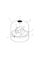
図1は本発明の実施形態の撮像装置の概略構成を示す斜視図である。同図において1は撮像装置全体を示し、2はPTZカメラの基台、3はパンの回転台、5はチルトの支持台で、撮影カメラ4をパン、チルト方向に回動できるように支持している。基台2、パン回転台3、チルト支持台5の内部には各々パン・チルト方向に回転させるモーター及びギアからなる駆動機構があり、カメラ駆動制御回路、映像信号制御回路などの基板と共に組み込まれている。撮影カメラ4はズーム、オートフォーカスの駆動機構を有し、パン・チルト動作と共に外部から制御可能なようになっている。基台2には撮影カメラを保護するポリカーボネイトなどで出来た透明なドーム6が固定されている。ドーム6の内面には、パン回転台3の回転軸の延長線上の位置に円錐ミラー7が固定されている。
FIG. 1 is a perspective view showing a schematic configuration of an imaging apparatus according to an embodiment of the present invention. In the figure, reference numeral 1 denotes the entire image pickup apparatus, 2 is a base of the PTZ camera, 3 is a pan rotation base, 5 is a tilt support base, and supports the photographing camera 4 so that it can be rotated in the pan and tilt directions. ing. Inside the
基台2にはPTZカメラの撮影方向の基準を示すマーク8が設けられており、撮影カメラ4で撮影する全方位画像の基準の方向とする。
The
次に、図2は本実施形態の撮像装置の側面図で、PTZカメラと全方位カメラの撮影モードを説明するものである。図2(a)はPTZカメラとして使用する場合で円錐ミラー7が配置してある領域を除き、ほぼ360°の領域を任意に拡大撮影することができる。図2(b)は全方位カメラとして使用する場合で、撮影カメラ4を円錐ミラー7の中心に向けて保持することで、図のように360°の領域を同時に撮影することができる。このように1台のPTZカメラで、撮影カメラの方向を変えるだけで、全方位カメラとしての機能を持たせることができる。 Next, FIG. 2 is a side view of the image pickup apparatus of the present embodiment, and explains the shooting modes of the PTZ camera and the omnidirectional camera. FIG. 2A shows a case where it is used as a PTZ camera, and an area of approximately 360 ° can be arbitrarily magnified except for an area where the conical mirror 7 is disposed. FIG. 2B shows a case where the camera is used as an omnidirectional camera. By holding the photographing camera 4 toward the center of the conical mirror 7, a 360 ° region can be photographed simultaneously as shown in the figure. Thus, the function as an omnidirectional camera can be provided by only changing the direction of the photographing camera with a single PTZ camera.
次に、図3において本実施形態の撮像装置のシステム全体構成を説明する。図中において点線で囲まれた部分は撮像装置全体1を示し、装置内部の電気回路の構成を表している。31はカメラ駆動制御回路、32は撮影カメラ4の撮像素子から出力される映像信号をデジタル信号に変換し、画素補間処理や色変換処理を行い、撮像データに変換する画像信号処理回路である。33はメモリ制御回路で、画像信号処理回路32、メモリ34を制御し、撮像データの取得と格納などを行う。
Next, the overall system configuration of the imaging apparatus according to the present embodiment will be described with reference to FIG. In the drawing, a portion surrounded by a dotted line indicates the entire imaging apparatus 1 and represents a configuration of an electric circuit inside the apparatus.
メモリ34は揮発性メモリまたは不揮発性メモリからなるメモリで、撮像データを一時的に格納したり、システムコントローラ35の動作制御の処理プログラムの格納領域や、システムコントローラ35の作業領域として使用することができる。
The memory 34 is a volatile memory or a non-volatile memory, and can be used as a storage area for processing programs for the operation control of the
37は映像符号化回路で撮像データをJPEGなどの符号化方式で圧縮符号化する。36は通信制御回路で、撮像データ、撮影制御データなどを送信・受信するものである。40は内部バスで、撮像データ、各種の制御信号を伝送するもので、システムコントローラ35は内部バス40を通して、メモリ制御回路33、映像符号化回路37や通信制御回路36を制御し、全体の撮像装置の制御を行うものである。
41はネットワーク回線で、それを介して遠隔に置かれたパーソナルコンピュータ42とモニタ43からなるモニタ装置に撮像データを転送し、モニタ43にその映像を表示することができる。
Reference numeral 41 denotes a network line, which can transfer image data to a monitor device including a
次に以上のように構成される撮像装置の動作について説明する。撮影カメラ4の映像信号は画像信号処理回路32によりデジタルの撮像データに変換され、画素補間処理や色変換処理が行われ、メモリ制御回路33により映像フレームごとに一時的にメモリ34に格納される。
Next, the operation of the imaging apparatus configured as described above will be described. The video signal from the photographic camera 4 is converted into digital image data by the image
次に、撮像データは映像符号化回路37により符号化され、通信制御回路36に送られ、ネットワーク回線41に送出される。ここで、ネットワークは例えばTCP/IPプロトコルを用いたインターネットのネットワークである。
Next, the imaging data is encoded by the
パーソナルコンピュータ42は符号化された撮像データを受け取り、パーソナルコンピュータ42に搭載された本撮像装置用のコントロールプログラムにより復号化処理を行い、モニタ43に撮影画像の表示を行う。
The
また、パーソナルコンピュータ42に搭載された撮像装置用のコントロールプログラムは撮影カメラのパン・チルト・ズームの動作の制御を行うことができ、コントロールプログラムから出力されるカメラの制御信号はパーソナルコンピュータ42からネットワーク回線41に送出される。撮像装置の通信制御回路36はそのカメラ制御信号を受信し、システムコントローラ35に伝達されて、カメラ駆動制御回路31を通して撮影カメラに所望の動作させることが出来る。
The control program for the image pickup apparatus mounted on the
図4は本実施形態によるモニタ43への撮影画像の表示例を示す図である。モニタ43の画面401にはコントロールプログラムにより全方位画像表示用ウインドウ402、ズーム画像表示用ウインドウ403、パン・チルト操作用ボタン404、ズーム操作用ボタン405、全方位撮影ボタン406が表示されている。
FIG. 4 is a diagram illustrating a display example of a captured image on the
全方位画像表示用ウインドウ402には撮像装置が全方位撮影モードのとき撮影されたリング状画像をコントロールプログラムにより歪み補正して横長に変換した画像が表示される。また、ズーム画像表示用ウインドウ403には撮像装置がPTZ撮影モードのときのズーム画像が表示される。
The omnidirectional image display window 402 displays an image obtained by correcting the distortion of a ring-shaped image captured when the imaging apparatus is in the omnidirectional imaging mode and converting the image into a landscape shape. The zoom
パン・チルト操作用ボタン404は方向キーが配置してあり、撮影カメラをリアルタイムにパン・チルト方向に移動させることができ、ズーム操作用ボタン405のスライドバーによりズーム比を変えることができる。
The pan /
全方位撮影ボタン406は撮影カメラを円錐ミラーの方向に向け、全方位画像を取得するモードに設定するものである。 The omnidirectional shooting button 406 is used to set a mode for acquiring an omnidirectional image by directing the shooting camera in the direction of the conical mirror.
次にこの撮像装置を用いたシステムのコントロールプログラムの制御フローを図5のフローチャートに示す。 Next, the control flow of the control program of the system using this imaging apparatus is shown in the flowchart of FIG.
パーソナルコンピュータ42のコントロールプログラムを動作させると、上記画面がモニタ43上に表示され、最初に、ステップ501で撮影カメラは全方位撮影モードとなるように、パン・チルト動作により円錐ミラーの方向に向けられる。その際、撮影カメラは基台のマーク位置を基準とし、その方向が全方位画像の原点となるようにパンの方向を合わせ、チルト動作により円錐ミラーの方向に向けられる。また、撮影カメラのズームは全方位の撮影に適した所定のズーム比に設定され、オートフォーカスも全方位撮影に適したフォーカス位置に固定される。
When the control program of the
ステップ502では全方位画像を撮像装置から取得し、全方位画像表示用ウインドウ402に歪み補正した画像を表示する。 In step 502, an omnidirectional image is acquired from the imaging apparatus, and the distortion-corrected image is displayed in the omnidirectional image display window 402.
次にステップ503で、観察者が全方位画像表示用ウインドウ402の画像上でマウスなどで拡大する領域を対角のコーナーで指示することにより、それに対応した拡大画像フレーム205が表示される。ステップ504では全方位画像表示用ウインドウ402を静止画に切換えて保存し、ステップ505で撮影カメラを円錐ミラーから切換えて、PTZモードにして全方位画像表示用ウインドウ402上で指示された方向にパン・チルトの移動を行い、ズーム比も拡大画像フレーム205で指示したサイズに対応するズーム比に設定する。ステップ506ではズーム画像表示用ウインドウ403にズーム画像を表示して、ステップ507で表示画面上のパン・チルト操作用ボタン404とズーム操作用ボタン405により、撮影カメラのパン・チルト・ズーム操作が自由に出来るモードにする。
Next, in step 503, the observer designates an area to be enlarged with a mouse or the like on the image of the omnidirectional image display window 402, and the corresponding enlarged image frame 205 is displayed. In
観察者が再び全方位画像を観察するときはステップ508で画面上の全方位撮影ボタン406をクリックするとステップ501に戻り、全方位撮影モードに切換えることができ、全方位画像は静止画から動画に復帰する。
When the observer observes the omnidirectional image again, clicking the omnidirectional shooting button 406 on the screen in
上述のようなシステム構成にすることで、全方位撮影とPTZ撮影を容易に切換えて、全方位の領域内で、所望の観察領域を高い解像度でズーム撮影することができる。また、全方位撮影の光軸とパン回転台の回転軸が一致しているので、撮影被写体とカメラの距離による撮影方向の不一致は生じない。 With the system configuration as described above, it is possible to easily switch between omnidirectional imaging and PTZ imaging, and to perform zoom imaging of a desired observation area with high resolution within the omnidirectional area. In addition, since the optical axis for omnidirectional photographing and the rotational axis of the pan turntable are coincident, there is no discrepancy in photographing direction due to the distance between the photographing subject and the camera.
本実施形態では全方位撮影のミラーを円錐ミラーとして説明したが、双曲線ミラー、放物面ミラー、球面ミラーなどの凸面ミラーでもよい。また、凹凸のミラー曲面を複数組み合わせた全方位光学素子を用いても良い。 In the present embodiment, the omnidirectional mirror is described as a conical mirror. However, a convex mirror such as a hyperbolic mirror, a parabolic mirror, or a spherical mirror may be used. Moreover, you may use the omnidirectional optical element which combined multiple uneven | corrugated mirror curved surfaces.
本実施形態では撮影被写体を観察者が任意に選択してズーム撮影したが、全方位画像から被写体の動き検知を画像処理により行い、動き検知した領域を自動的にズーム撮影するようなシステムを構成することも可能である。 In this embodiment, the observer arbitrarily selects the subject to be photographed and zoomed in, but the system detects the subject's motion from the omnidirectional image by image processing and automatically zooms in on the motion-detected area. It is also possible to do.
(第2の実施形態)
図6は本発明による第2の実施形態の撮像装置の説明図である。第1の実施形態では全方位撮影ミラーをドームの内面に配置したが、図6(a)のようにドームの外側に透明な円筒部材8を取り付けその端部に円錐ミラーなどの全方位撮影ミラーを配置して、全方位撮影モードの時は図6(b)のように円筒部材8の円筒面から全方位撮影を行うようにしたものである。これにより従来のPTZカメラのドーム径を変更することなく、全方位撮影ミラーが付いたドームに取り替えるだけで全方位撮影の機能を追加できる。
(Second Embodiment)
FIG. 6 is an explanatory diagram of an imaging apparatus according to the second embodiment of the present invention. In the first embodiment, the omnidirectional photographing mirror is arranged on the inner surface of the dome. However, as shown in FIG. 6A, a transparent cylindrical member 8 is attached to the outer side of the dome, and an omnidirectional photographing mirror such as a conical mirror is attached to the end. In the omnidirectional imaging mode, omnidirectional imaging is performed from the cylindrical surface of the cylindrical member 8 as shown in FIG. This makes it possible to add an omnidirectional photographing function by simply replacing the dome with an omnidirectional photographing mirror without changing the dome diameter of the conventional PTZ camera.
また、図7には全方位撮影ミラーを交換可能にした構成で、全方位撮影ミラー72は円筒状の樹脂ブロックから出来ており、反射面73は凹面の曲面に金属反射膜蒸着して形成されており、ドーム6上の取り付け部71にねじ止めなどで交換可能に固定されている。全方位撮影ミラーの曲率を変更することで、上下方向の撮影視野角が変わるので、必要に応じて全方位撮影ミラーのみを交換することで最適な撮影視野角が得られる。
FIG. 7 shows a configuration in which the omnidirectional photographing mirror is replaceable. The omnidirectional photographing mirror 72 is made of a cylindrical resin block, and the reflecting
1 撮像装置全体
2 基台
3 パン回転台
4 撮影カメラ
5 チルト支持台
6 ドーム
7 円錐ミラー
31 カメラ駆動制御回路
32 画像信号処理回路
33 メモリ制御回路
35 システムコントローラ
36 通信制御回路
41 ネットワーク
42 パーソナルコンピュータ
43 モニタ
402 全方位画像表示用ウインドウ
403 ズーム画像表示用ウインドウ
404 パン・チルト操作用ボタン
405 ズーム操作用ボタン
406 全方位撮影ボタン
801 PTZカメラ
802 全方位カメラ
102 双曲線ミラー
DESCRIPTION OF SYMBOLS 1 The
Claims (3)
前記撮像装置に対して水平方向に前記撮影カメラの撮影方向を回転させるパン動作及び前記撮像装置に対して垂直方向に前記撮影カメラの撮影方向を回転させるチルト動作を制御する駆動制御手段と、
前記撮影カメラを保護するドームの一部であって前記駆動制御手段のパン動作の回転軸の延長線上に配置され、円錐、球、放物、または双曲線を含む曲面を少なくとも一つは有するミラーとを有し、
前記駆動制御手段が前記撮影カメラを前記パン動作の回転軸の延長線上に向けることにより前記撮影カメラが前記ミラーを介して撮影被写体を撮影するモードと、前記駆動制御手段が前記撮影カメラを前記パン動作の回転軸の延長線上とは異なる方向に向けることにより前記撮影カメラが前記ミラーを介さずに前記撮影被写体を撮影するモードと、を有することを特徴とする撮像装置。 An imaging apparatus having a photographing camera ,
Drive control means for controlling a panning operation for rotating the photographing direction of the photographing camera in a horizontal direction with respect to the imaging device and a tilting operation for rotating the photographing direction of the photographing camera in a vertical direction with respect to the imaging device ;
A mirror that is a part of a dome that protects the photographing camera and is disposed on an extension line of a rotation axis of the pan operation of the drive control means and has at least one curved surface including a cone, a sphere, a parabola, or a hyperbola; Have
The drive control means directs the photographing camera on an extension line of the rotation axis of the panning operation so that the photographing camera takes a photographed subject through the mirror; and the drive control means causes the photographing camera to move the panning camera. imaging apparatus characterized by having a mode for photographing the photographed object without passing through the imaging camera the mirror by orienting in a direction different from the extension of the axis of rotation of the operation.
前記指示手段は、モニタの画面上に表示させたボタンに対する前記観察者の操作に応じて、前記撮影カメラが前記ミラーを介して撮影被写体を撮影するモードで撮影するように前記駆動制御手段に指示することを特徴とする請求項1に記載の撮像装置。 It further has instruction means that can instruct the drive control means from outside,
The instruction unit instructs the drive control unit to shoot in a mode in which the photographic camera shoots a photographic subject through the mirror in response to an operation of the observer with respect to a button displayed on a monitor screen. The imaging apparatus according to claim 1 , wherein:
Priority Applications (1)
| Application Number | Priority Date | Filing Date | Title |
|---|---|---|---|
| JP2004298832A JP4448001B2 (en) | 2004-10-13 | 2004-10-13 | Imaging device |
Applications Claiming Priority (1)
| Application Number | Priority Date | Filing Date | Title |
|---|---|---|---|
| JP2004298832A JP4448001B2 (en) | 2004-10-13 | 2004-10-13 | Imaging device |
Publications (3)
| Publication Number | Publication Date |
|---|---|
| JP2006115091A JP2006115091A (en) | 2006-04-27 |
| JP2006115091A5 JP2006115091A5 (en) | 2007-08-09 |
| JP4448001B2 true JP4448001B2 (en) | 2010-04-07 |
Family
ID=36383255
Family Applications (1)
| Application Number | Title | Priority Date | Filing Date |
|---|---|---|---|
| JP2004298832A Expired - Fee Related JP4448001B2 (en) | 2004-10-13 | 2004-10-13 | Imaging device |
Country Status (1)
| Country | Link |
|---|---|
| JP (1) | JP4448001B2 (en) |
Families Citing this family (6)
| Publication number | Priority date | Publication date | Assignee | Title |
|---|---|---|---|---|
| JP4865477B2 (en) * | 2006-07-07 | 2012-02-01 | 三菱重工業株式会社 | Automatic bill collector |
| EP2187622A1 (en) | 2008-11-12 | 2010-05-19 | Axis AB | Camera assembly |
| JP5452183B2 (en) * | 2009-11-19 | 2014-03-26 | オリンパスイメージング株式会社 | Imaging device |
| US9110365B2 (en) | 2009-11-19 | 2015-08-18 | Olympus Corporation | Imaging apparatus |
| CN102789187B (en) * | 2012-07-05 | 2014-12-10 | 华为技术有限公司 | Identification method for pan-tilt equipment, pan-tilt equipment, camera and control system for pan-tilt equipment |
| CN114079733A (en) * | 2020-08-12 | 2022-02-22 | 茂傑国际股份有限公司 | Multifunctional photographic device |
-
2004
- 2004-10-13 JP JP2004298832A patent/JP4448001B2/en not_active Expired - Fee Related
Also Published As
| Publication number | Publication date |
|---|---|
| JP2006115091A (en) | 2006-04-27 |
Similar Documents
| Publication | Publication Date | Title |
|---|---|---|
| US8059185B2 (en) | Photographing apparatus, image display method, computer program and storage medium for acquiring a photographed image in a wide range | |
| JP3792901B2 (en) | Camera control system and control method thereof | |
| US7450165B2 (en) | Multiple-view processing in wide-angle video camera | |
| KR102087450B1 (en) | A System and Method for Processing a Very Wide Angle Image | |
| US20100045773A1 (en) | Panoramic adapter system and method with spherical field-of-view coverage | |
| JP2004282162A (en) | Camera, and monitoring system | |
| JP2012520650A (en) | Intelligent surveillance camera device and video surveillance system employing the same | |
| KR101685418B1 (en) | Monitoring system for generating 3-dimensional picture | |
| KR20050051575A (en) | Photographing apparatus and method, supervising system, program and recording medium | |
| WO2004084542A1 (en) | Panoramic picture creating method and device, and monitor system using the method and device | |
| KR101689534B1 (en) | Multiscale Imaging System | |
| KR20120108747A (en) | Monitoring camera for generating 3 dimensional scene and method thereof | |
| US8692879B2 (en) | Image capturing system, image capturing device, information processing device, and image capturing method | |
| JP4448001B2 (en) | Imaging device | |
| JP7150456B2 (en) | IMAGING SYSTEM, INFORMATION PROCESSING DEVICE, CONTROL METHOD OF INFORMATION PROCESSING DEVICE, AND PROGRAM | |
| CN112218048B (en) | Intelligent monitoring system | |
| JPH118845A (en) | Panoramic image generation device and its method | |
| KR20110136907A (en) | Wide area surveillance system and monitoring data processing method in the same | |
| JP2000341574A (en) | Camera device and camera control system | |
| JP2004153605A (en) | Image pickup device and system for transmitting pick-up image | |
| KR102009988B1 (en) | Method for compensating image camera system for compensating distortion of lens using super wide angle camera and Transport Video Interface Apparatus used in it | |
| JP2006025340A (en) | Wide angle imaging apparatus, imaging system, and control method thereof | |
| JP2004282163A (en) | Camera, monitor image generating method, program, and monitoring system | |
| CN112073630A (en) | Image pickup apparatus, control method for image pickup apparatus, and recording medium | |
| JP2012099887A (en) | Imaging device |
Legal Events
| Date | Code | Title | Description |
|---|---|---|---|
| A521 | Request for written amendment filed |
Free format text: JAPANESE INTERMEDIATE CODE: A523 Effective date: 20070625 |
|
| A621 | Written request for application examination |
Free format text: JAPANESE INTERMEDIATE CODE: A621 Effective date: 20070625 |
|
| A977 | Report on retrieval |
Free format text: JAPANESE INTERMEDIATE CODE: A971007 Effective date: 20091007 |
|
| A131 | Notification of reasons for refusal |
Free format text: JAPANESE INTERMEDIATE CODE: A131 Effective date: 20091013 |
|
| A521 | Request for written amendment filed |
Free format text: JAPANESE INTERMEDIATE CODE: A523 Effective date: 20091209 |
|
| TRDD | Decision of grant or rejection written | ||
| A01 | Written decision to grant a patent or to grant a registration (utility model) |
Free format text: JAPANESE INTERMEDIATE CODE: A01 Effective date: 20100119 |
|
| A01 | Written decision to grant a patent or to grant a registration (utility model) |
Free format text: JAPANESE INTERMEDIATE CODE: A01 |
|
| A61 | First payment of annual fees (during grant procedure) |
Free format text: JAPANESE INTERMEDIATE CODE: A61 Effective date: 20100121 |
|
| FPAY | Renewal fee payment (event date is renewal date of database) |
Free format text: PAYMENT UNTIL: 20130129 Year of fee payment: 3 |
|
| R150 | Certificate of patent or registration of utility model |
Ref document number: 4448001 Country of ref document: JP Free format text: JAPANESE INTERMEDIATE CODE: R150 |
|
| FPAY | Renewal fee payment (event date is renewal date of database) |
Free format text: PAYMENT UNTIL: 20140129 Year of fee payment: 4 |
|
| LAPS | Cancellation because of no payment of annual fees |