JP4416990B2 - System for operating a device in vivo - Google Patents
System for operating a device in vivo Download PDFInfo
- Publication number
- JP4416990B2 JP4416990B2 JP2002229001A JP2002229001A JP4416990B2 JP 4416990 B2 JP4416990 B2 JP 4416990B2 JP 2002229001 A JP2002229001 A JP 2002229001A JP 2002229001 A JP2002229001 A JP 2002229001A JP 4416990 B2 JP4416990 B2 JP 4416990B2
- Authority
- JP
- Japan
- Prior art keywords
- tube
- imaging device
- mode
- sensing device
- vivo
- Prior art date
- Legal status (The legal status is an assumption and is not a legal conclusion. Google has not performed a legal analysis and makes no representation as to the accuracy of the status listed.)
- Expired - Fee Related
Links
Images


Classifications
-
- A—HUMAN NECESSITIES
- A61—MEDICAL OR VETERINARY SCIENCE; HYGIENE
- A61B—DIAGNOSIS; SURGERY; IDENTIFICATION
- A61B1/00—Instruments for performing medical examinations of the interior of cavities or tubes of the body by visual or photographical inspection, e.g. endoscopes; Illuminating arrangements therefor
- A61B1/00163—Optical arrangements
- A61B1/00174—Optical arrangements characterised by the viewing angles
- A61B1/00181—Optical arrangements characterised by the viewing angles for multiple fixed viewing angles
-
- A—HUMAN NECESSITIES
- A61—MEDICAL OR VETERINARY SCIENCE; HYGIENE
- A61B—DIAGNOSIS; SURGERY; IDENTIFICATION
- A61B1/00—Instruments for performing medical examinations of the interior of cavities or tubes of the body by visual or photographical inspection, e.g. endoscopes; Illuminating arrangements therefor
- A61B1/00163—Optical arrangements
- A61B1/00174—Optical arrangements characterised by the viewing angles
- A61B1/00183—Optical arrangements characterised by the viewing angles for variable viewing angles
-
- A—HUMAN NECESSITIES
- A61—MEDICAL OR VETERINARY SCIENCE; HYGIENE
- A61B—DIAGNOSIS; SURGERY; IDENTIFICATION
- A61B1/00—Instruments for performing medical examinations of the interior of cavities or tubes of the body by visual or photographical inspection, e.g. endoscopes; Illuminating arrangements therefor
- A61B1/04—Instruments for performing medical examinations of the interior of cavities or tubes of the body by visual or photographical inspection, e.g. endoscopes; Illuminating arrangements therefor combined with photographic or television appliances
- A61B1/041—Capsule endoscopes for imaging
-
- A—HUMAN NECESSITIES
- A61—MEDICAL OR VETERINARY SCIENCE; HYGIENE
- A61B—DIAGNOSIS; SURGERY; IDENTIFICATION
- A61B1/00—Instruments for performing medical examinations of the interior of cavities or tubes of the body by visual or photographical inspection, e.g. endoscopes; Illuminating arrangements therefor
- A61B1/04—Instruments for performing medical examinations of the interior of cavities or tubes of the body by visual or photographical inspection, e.g. endoscopes; Illuminating arrangements therefor combined with photographic or television appliances
- A61B1/05—Instruments for performing medical examinations of the interior of cavities or tubes of the body by visual or photographical inspection, e.g. endoscopes; Illuminating arrangements therefor combined with photographic or television appliances characterised by the image sensor, e.g. camera, being in the distal end portion
- A61B1/053—Instruments for performing medical examinations of the interior of cavities or tubes of the body by visual or photographical inspection, e.g. endoscopes; Illuminating arrangements therefor combined with photographic or television appliances characterised by the image sensor, e.g. camera, being in the distal end portion being detachable
Description
【0001】
【発明の属する技術分野】
この発明は、生体内(in vivo)での診断および/または治療の分野に関する。より特定的には、この発明は生体内でセンシング装置を操作するためのシステムおよび方法に関する。
【0002】
【従来の技術】
さまざまな身体系の診断および治療において生体内ツールが用いられる。生体内センシングは、医者が最小限の侵入によって体内の特徴および出来事を安全かつ容易に検出する能力を促進できる。生体内診断および/または治療プロセス(特定の生体内場所に対する手術手順、生検またはサンプリング手順、および送出治療など)は、今日利用可能な小型センサによって促進され得る。小型センサは、温度、pHまたは圧力など、体内腔における生体内状態を検知するために用いられ得る。また、体内腔または空洞の視覚的調査のためにイメージセンサが用いられる。腹腔鏡を用いる手術手順および胃腸病学手順など、体内腔および空洞における医学手順は典型的に、生体内で見ると同時に手順を行なうための視覚またはイメージング手段を通常含む、トロカールまたは内視鏡を通される医学装置によって行なわれる。
【0003】
今日利用可能な内視鏡は典型的に、管の末端に位置するイメージセンサおよび観察レンズを有する(体内に挿入される)外側管と、体内腔の目的の部位に照明をもたらすための複数の光透過性ファイバと、外側管の内側のチャネルとを含む。チャネルは、空気の挿入、体内腔の通気、水注入、観察レンズの洗浄、吸引のために、および鉗子、ステント、切開または組織除去装置、カテーテルなどの装置を通すために用いられる。外側管は制御体に接続され、その制御体は医者が保持し、またそれは内視鏡およびチャネル機能の活性化および制御のためのボタンおよび滑車を備えてもよい。アンビリカルケーブルは制御体を光源およびビデオプロセッサに接続する。
【0004】
イメージセンサによって与えられる写角、または内視鏡の先端に位置するあらゆるその他のセンサの体内腔の遠隔または隠れた部分に対するアクセス可能性は、内視鏡先端の操作性に依存する。典型的には、内視鏡先端は移動範囲が限られ得るため、たとえば広い写角は通常、内視鏡先端における観察レンズまたはその他の光学素子の特定的な設計によって達成される。
【0005】
自律センサは内視鏡がアクセス不可能な体内腔の部分にアクセスし得るが、自律装置は容易に制御されず、内視鏡を用いて行ない得る手順の多くはこのような自律装置によって行なうことができない。
【0006】
したがって、生体内手順の促進された性能が必要とされる。
【0007】
【発明の概要】
この発明の実施例は、生体内においてセンシング装置を操作するためのシステムおよび方法を提供する。特定の実施例は、内視鏡ならびに/または操作可能なセンシング装置を有するその他の生体内診断および/もしくは治療ツールを提供することによって、生体内手順の性能を促進してもよい。
【0008】
この発明の実施例に従ったシステムは、末端および基端を有する管と、管の末端に変更可能に接続され得る生体内センシング装置とを含む。典型的には、その末端が体内腔に挿入されてもよく、一方基端は外部オペレータにアクセス可能であってもよい。管は、たとえば内視鏡検査の分野において公知であるような、ツール、水、空気などを通すためのチャネルを含んでもよい。
【0009】
この発明の実施例に従うと、センシング装置は当該技術分野において公知のあらゆる好適なセンシング装置であってもよく、少なくとも2つの変更可能なモードにおいて管の末端に接続されてもよい。少なくとも1つの第1のモードにおいて、センシング装置は管の末端に接続されて管の長手軸に沿って連続体を形成してもよい。少なくとも1つの第2のモードにおいて、センシング装置は管の長手軸に沿って連続体を形成しないように管の末端に接続されてもよい。実施例の1つにおいて、第2のモードにおけるセンシング装置は、管の長手軸に対して本質的に平行に、管に横付けにして管の末端に接続される。
【0010】
いくつかの実施例に従うと、システムは管およびセンシング装置を結合もしくは接続するための、ならびに/または第1のモードから第2のモードへの変更をもたらすための、トラック、ランプまたはリトラクタブルアームまたはばねなどの機構を含んでもよい。
【0011】
この発明の実施例に従った方法において、この発明に従ったシステムは、センシング装置が第1のモードにおいて管の末端に接続された状態で生体内に挿入される。管はおそらくはセンシング装置に支援されて所望の場所に移動し、その点においてセンシング装置の管の末端への接続が第2のモードに変更される。
【0012】
この発明は、添付の図面とともに以下の詳細な説明によってより完全に理解されかつ認識されるであろう。
【0013】
【詳細な説明】
以下の説明において、この発明のさまざまな局面を記載する。説明の目的のために、この発明の完全な理解を提供するために特定の構成および詳細を示す。しかし、この発明はここに提供される特定の詳細なしに実行されてもよいことが当業者に明らかになるであろう。さらに、この発明を不明確にしないために、周知の特徴は省略または簡略化され得る。
【0014】
実施例の1つにおいて、この発明のシステムは診断および/または治療手順に用いられてもよく、ここではツールまたはツールを挿入するための作業チャネルを含む管が、管の末端に位置決めされかつ管の長手軸に沿って連続体を形成するように接続されたセンシング装置の支援によって、体内腔の所望の場所に誘導される。所望の場所において、管の末端に対するセンシング装置の接続は第2のモードに変更され、ここではたとえばセンシング装置は管に横付けにして位置決めされ、管の長手軸に沿って連続体を形成しない。第1のモードにおいて、管の末端はセンシング装置によって妨げられてもよい。しかし、第2のモードにおいては管の末端はセンシング装置によって妨げられず、管は体内腔にツールを挿入するため、および/または体内腔の通気などのために用いられ得る。さらに、第2のモードにおいて、センシング装置は生体内手順の実行を助け続けてもよい。たとえば、この発明の実施例において、センシング装置はイメージングユニットであってもよく、それはイメージセンサと、光学系と、照明源と、おそらくは受信ユニットに画像データを送信するための送信機とを含んでもよい。この実施例において、第1のモードにおけるイメージングユニットは、体内腔における管の動きを妨げずに管の所望の場所への誘導を助ける。第2のモードにおいて、イメージングユニットは外部オペレータに対して体内腔の視界を提供し、オペレータが管およびその作業チャネルまたはツールを用いて生体内手順を行なうことを助ける。
【0015】
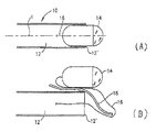
この発明のシステムの実施例が概略的に例示された図1(A)および1(B)を参照する。システム10は管12と、管の末端12′において管12に接続されたセンシング装置14とを含む。管12は必要に応じて柔軟であっても硬くてもよい。たとえば、結腸鏡手順およびGI管(胃腸管)の上側部分における手順には、通常柔軟な内視鏡が用いられる。管12は、特定の要求に従って、公知のカテーテル、内視鏡、針、ステント、腹腔鏡、硬い内視鏡などと同様に設計および製作されてもよい。
【0016】
センシング装置14は、あらゆる好適な生体内センシング装置であってもよい。実施例の1つにおいて、センシング装置14はGI管をイメージングするためのイメージングユニットである。センシング装置14は、この発明と共通の譲受人に譲渡されかつここに引用により援用される、2000年12月21日に公開された「光学系(An Optical System)」と題する公開番号第WO00/76391号に記載されるイメージングユニットと類似のものであってもよい。別の実施例においては、センシング装置14はイダン(Iddan)に対する米国特許第5,604,531号または2001年9月13日に公開された「生体内イメージングのための装置およびシステム(A Device and System for in vivo Imaging)」と題する公開番号第WO01/65995号に記載される装置などのカプセル形自律イメージセンサであってもよく、これらは両方ともこの発明と共通の譲受人に譲渡され、ここに引用により援用される。センシング装置14は、CCDまたはCMOSイメージセンサなどのイメージセンサ、(レンズおよび/または鏡および/またはプリズムを典型的に含む)光学系、LEDなどの照明源、および画像データを受信ユニットに送信するための(無線または有線)送信機を含んでもよい。任意には、センシング装置14のこれらの素子はすべて無線であってもよく、たとえばセンシング装置14に含まれるバッテリによって電力を供給されてもよく、またはセンシング装置14に対する電線接続を通じて電力を供給されてもよい。電線は特に画像データの有線送信のために用いられてもよい。
【0017】
図1(A)において、センシング装置14は、管12につながれた弾性ワイヤ16を通じて、管12の末端12′に近接して管12に接続される。ワイヤ16は緩められ、センシング装置14は管12の長手軸(I)に沿った連続体において管12に取付けられる。図1(B)に例示される実施例において、センシング装置14は後ろの弾性ワイヤ16を引っ張りながら管12に沿って前進する。センシング装置14が管12を出ると、ランプ18が管12の末端12′の前に降下する。管の末端において管に接続されるランプ18は、弾性ワイヤ16を押してセンシング装置14にランプ18を上らせ、それを管12の長手軸に対して本質的に平行に管12に横付けする。任意には、センシング装置14はその位置を固定するためにランプ18または管12に留められてもよい。この点において弾性ワイヤ16は教示され、一旦センシング装置14が管12に横付けされた位置から解放されると、センシング装置14を管12中の初期位置に引き戻す(初期位置はたとえば図1(A)に示される)。弾性ワイヤ16はまた、ランプ18をその上昇位置(図示せず)に押してもよい。代替的には、ランプ18が活動的に上昇することによって弾性ワイヤ16における圧力を解放し、弾性ワイヤ16がセンシング装置14を管12中の初期位置(図1(A))に引き戻すことを可能にしてもよい。ランプ18の降下および上昇、ならびに/またはセンシング装置14の管12を通る前進の制御は、公知の方法によって達成できる。ランプ18の制御および/またはセンシング装置14の移動の制御のために、外部オペレータはばねおよび滑車を用い得る。代替的には、ランプ18の制御および/またはセンシング装置14の移動の制御のために受動機構が用いられてもよい。たとえば、ランプ18は、双安定材料で作られたラッチ、またはランプの降下を可能にするために必要に応じて加熱もしくは冷却される形状記憶ポリマーによって制御されてもよい。同様に、管12を通るセンシング装置14の前進は、双安定材料のばねまたは形状記憶ポリマーによって制御されてもよい。
【0018】
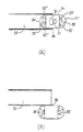
図2(A)および2(B)に例示される実施例において、センシング装置24はばね26を通じて管22に結合される。典型的には、ばね26またはあらゆるその他の好適なリトラクタブルもしくは非リトラクタブルアームは、管の外周または(たとえば図1(B)に例示されるように)その内径において管22に接続される。たとえば、図2(A)に例示される第1のモードにおいて、システム20が腹またはGI管もしくはその他の体内腔(血管など)を通って押される際に、センシング装置24は管22に固定されることによって管22の長手軸に沿って管22と連続体を形成し、ばね26は延ばされている。第1のモードは体内腔を通るシステム20の容易な通過を可能にする。
【0019】
図2(B)に例示される第2のモードにおいて、センシング装置24はもはや管22に固定されていない。ばね26は反動してセンシング装置24を引っ張るため、センシング装置は管22に横付けにして位置決めされる。この第2のモードは、たとえばシステム20がもう体内腔を通って動かされないときに(すなわち手術またはその他の手順が行なわれる場所において)望ましい。
【0020】
管22に対するセンシング装置24の固定および解放は、たとえば分解性の接着剤を用いたり、または管22の末端22′を機械的に離すことによってそのセンシング装置24に対する保持を解放するなどの、公知の方法によって達成されてもよい。
【0021】
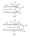
図3(A)および3(B)に例示される実施例において、イメージングユニット34はヒンジ38を通じて、または任意には前述と同様に、管32に変更可能に接続される。イメージングユニット34は2つの観察端部34′および34″を含み、その各々は照明源33′および33″ならびに2つの光路をそれぞれ含む。(光路は、生体内部位に入射されてそこからCMOSイメージセンサなどのイメージセンサに送られる光線が辿る経路である。)2つの光路において、送られた光はそれぞれイメージセンサ35′および35″に向けられる。イメージングユニット34は、イメージングユニット34の電気素子全体に電力を提供し得る電源(図示せず)と、イメージセンサ35′および35″から画像信号を送信するための送信機36およびアンテナ37とをさらに含む。任意には、観察端部34′および34″は前述のWO00/76391号に記載されるような光学ウィンドウを含んでもよい。
【0022】
たとえば図3(A)に例示される第1のモードにおいて、イメージングユニット34は管32に固定されることによって、管32の長手軸に沿って管32と連続体を形成する。体内腔の画像はイメージセンサ35′によって得られてもよく、一方イメージセンサ35″および照明源33″は不活性であってもよい。
【0023】
たとえば図3(B)に例示される第2のモードにおいて、イメージングユニット34はもはや管32に固定されていない。ヒンジ38はイメージングユニット34が管32の外に前進することを可能にする。しかし、一旦イメージングユニット34が管32から出ると、それは重力によって下に引っ張られ、管32に横付けになるか、またはおそらくは管32に対して本質的に直角に、ヒンジ38にぶら下がる。イメージングユニット34の指向性が典型的に変えられることによって、最初は前方を見ていたイメージセンサ35′が後方または側方を見るようになる。第2のモードにおいて、典型的には前方を見ているイメージセンサ35″が照明源33″とともに活性化されてもよい。この第2のモードにおいて、イメージングユニット34は、ユニットの2つの端部からたとえばGI管などの体内腔の映像を同時に得ることができてもよく、それによって体内腔の広い写角を可能にしてもよい。さらに、管32は空にされて、たとえば(以下に説明するような)生体内手順を行なうために用いられ得る。
【0024】
イメージセンサ35″および35′によってそれぞれ得られる2つの画像(典型的には前方および後方)は、分離して、または単一の組合わせられた画像として表示できる。実施例の1つにおいて、体内腔からの信号の同時送信のために、分離した送信機および送信のチャネルが各イメージセンサに割当てられてもよい。代替的には、たとえば異なる搬送周波数を用いることなどによって、単一の送信機(送信機36など)および送信のチャネルにおいていくつかのイメージセンサの出力が組合わされてもよい。単一のチャネルにおける異なるイメージセンサからの情報の組合わせは、毎回異なるイメージセンサからのビットを選択してすべての画像をほぼ同時に送信することによって行なわれても、または画像を順番に送信することによって行なわれてもよい。
【0025】
実施例の1つに従うと、イメージセンサ35′および35″によって得られる2つの画像は、たとえば異なる画像における各像点(ピクセル)を単一の組合わせられた画像の別の点(ピクセル)に割当てるアルゴリズムを適用することによって、受信ユニットに送信される前に単一の画像に組合わされてもよい。しかし、画像を単一画像に組合わせる動作は通常かなりの処理労力および計算リソースを必要とするため、この動作は通常、外部記録/処理装置において(イメージセンサから送信された画像を受取った後に)オフラインで行なわれる。画像の分離は、公知の画像処理法によって、または異なる画像に対してタグを付加することによって、つまりたとえばイメージセンサ35′から得られた画像に対してあるコードを付加し、イメージセンサ35″から得られた画像に対して異なるコードを付加することによって、オンラインで行なわれてもよい。
【0026】
図4(A)および4(B)に、この発明の別の実施例が概略的に例示される。この実施例において、システム40はチャネル48を有する管42を含み、そのチャネルを通ってアーム47が延在し、さらに体内腔に水および/または空気および/またはツールを通すためのチャネル41および43を含む。アーム47の末端には、センサ装置44を保持するための回転可能な保持ユニット49がある。アーム47および回転可能な保持ユニット49はどちらも外部オペレータによって制御可能である。代替的には、センサ装置44がアーム47の末端に直接かつ回転可能に接続されることによって保持ユニット49の必要性をなくしてもよい。
【0027】
たとえば図4(A)に例示される第1のモードにおいて、チャネル48、41および43の末端開口部は回転可能な保持ユニット49によって塞がれてもよい。センサ装置44は管42の長手軸に沿って管42と連続体を形成する。たとえば図4(B)に例示される第2のモードにおいて、アーム47は外部オペレータによってたとえば前方に押され、回転可能ユニット49およびそれとともにセンサ装置44が管42の末端から離されて、チャネル48、43および41の末端開口部を空ける。これらのチャネルは、生体内手順を行なうために体内腔に水/空気および/またはツールを通すために用い得る。同時に、回転可能ユニット49が(図4(B)において矢印によって示されるように)回転されることによって、体内腔の通常はアクセス不可能な部分へのセンサ装置44のアクセスを可能にしてもよい。たとえば、前述のように回転させ得るイメージセンサによって、体内腔の広い写角が達成できる。
【0028】
図5は、この発明の実施例に従ったシステムの管のより詳細な概略図を例示する。システム50は、管52およびセンサ装置54を含む。センサ装置54は前述のような光学ウィンドウ54′を有するイメージング装置であってもよく、管52は胃内出血の場合に用いられる内視鏡であってもよい。
【0029】
管52は、必要に応じてGI管を洗い流すかまたは通気するための水/空気チャネル51と、内出血を止めるための帯結紮または焼灼ツールなどのツールをGI管に通すためのツールチャネル53と、GI管の内容物を空けるための吸引チャネル55と、光学ウィンドウ54′を洗浄するための水ジェットチャネル57とを含む。管52はその基端において制御ハンドルに接続されて、内視鏡の分野において公知の態様で動作され得る。
【0030】
この発明のシステムは、おそらくはシステムのセンサ装置によって支援されて、生体内の場所に容易に誘導され得る。生体内の場所において、センサ装置は前述の実施例のいずれかにおいて説明したようにたとえばシステムの管から離れるように動かすことができ、センサ装置のアクセス可能性および管の経済的な使用を可能にする。
【0031】
この発明の実施例に従うと、生体内手順を行なうための方法が提供される。生体内手順は、イメージングもしくはサンプリングなどの診断手順、または結紮などの治療手順を含んでもよい。実施例の1つに従うと、前述において例示したようなシステムは、第1のモードにおいて管の末端にセンシング装置が接続された状態で生体内に挿入されてもよい。管はおそらくはセンシング装置によって支援されながら所望の場所に動かされ、その点において管の末端へのセンシング装置の接続が第2のモードに変更される。典型的には、管の末端へのセンシング装置の接続が第2のモードに変更されるときに、管中の作業チャネルが潅注、通気または手術のために用いられてもよい。
【0032】
前述の実施例のいずれかを好適に組合わせたシステムおよび方法もこの発明に含まれることが当業者に認識されるであろう。さらに、この発明の実施例はイメージセンサに関して記載されたが、温度センシング装置、pHセンサ、圧力センサ、超音波撮像装置などのその他の好適な生体内センシング装置が用いられてもよいことが認識されるであろう。この発明は前述において特定的に示しかつ説明したものに制限されないことが認識されるであろう。この発明の範囲は添付の請求項によってのみ定められる。
【図面の簡単な説明】
【図1】 この発明の実施例に従ったシステムを例示する概略的な側面図である。
【図2】 この発明の別の実施例に従ったシステムを例示する概略的な側面図である。
【図3】 この発明のさらに別の実施例に従ったシステムを例示する概略的な側面図である。
【図4】 この発明のさらなる実施例に従ったシステムを例示する概略的な側面図である。
【図5】 この発明のさらに別のさらなる実施例に従ったシステムを例示する概略的な側面図である。
【符号の説明】
10 システム、12 管、14 センシング装置。[0001]
BACKGROUND OF THE INVENTION
The present invention relates to the field of in vivo diagnosis and / or treatment. More specifically, the present invention relates to a system and method for operating a sensing device in vivo.
[0002]
[Prior art]
In vivo tools are used in the diagnosis and treatment of various body systems. In-vivo sensing can facilitate the ability of doctors to detect body features and events safely and easily with minimal intrusion. In-vivo diagnostic and / or treatment processes (such as surgical procedures for specific in-vivo locations, biopsy or sampling procedures, and delivery therapy) can be facilitated by small sensors available today. Miniature sensors can be used to sense in vivo conditions in the body lumen, such as temperature, pH or pressure. Image sensors are also used for visual inspection of body cavities or cavities. Medical procedures in body cavities and cavities, such as laparoscopic surgical procedures and gastroenterology procedures, typically include trocars or endoscopes that usually include visual or imaging means for performing the procedure while viewed in vivo. Performed by a threaded medical device.
[0003]
Endoscopes available today typically have an outer tube (inserted into the body) having an image sensor and an observation lens located at the end of the tube, and a plurality of to provide illumination to a target site in the body lumen It includes a light transmissive fiber and a channel inside the outer tube. Channels are used for air insertion, body cavity ventilation, water injection, observation lens cleaning, aspiration, and for passing devices such as forceps, stents, incision or tissue removal devices, catheters and the like. The outer tube is connected to a control body, which is held by a physician, and may include buttons and pulleys for activation and control of the endoscope and channel functions. The umbilical cable connects the control body to the light source and the video processor.
[0004]
The viewing angle provided by the image sensor, or the accessibility of any other sensor located at the endoscope tip to the remote or hidden part of the body lumen, depends on the operability of the endoscope tip. Typically, for example, a wide angle of view is usually achieved by a specific design of the observation lens or other optical element at the endoscope tip, since the endoscope tip can have a limited range of movement.
[0005]
Autonomous sensors can access parts of the body cavity that the endoscope cannot access, but the autonomous device is not easily controlled, and many of the procedures that can be performed using the endoscope are performed by such an autonomous device I can't.
[0006]
Therefore, enhanced performance of in vivo procedures is required.
[0007]
SUMMARY OF THE INVENTION
Embodiments of the present invention provide systems and methods for operating a sensing device in vivo. Certain embodiments may facilitate the performance of in vivo procedures by providing an endoscope and / or other in vivo diagnostic and / or therapeutic tools with operable sensing devices.
[0008]
A system according to an embodiment of the invention includes a tube having a distal end and a proximal end and an in-vivo sensing device that can be variably connected to the distal end of the tube. Typically, the distal end may be inserted into a body lumen, while the proximal end may be accessible to an external operator. The tube may include channels for the passage of tools, water, air, etc., as is known, for example, in the field of endoscopy.
[0009]
According to embodiments of the invention, the sensing device may be any suitable sensing device known in the art and may be connected to the end of the tube in at least two modifiable modes. In at least one first mode, the sensing device may be connected to the end of the tube to form a continuum along the longitudinal axis of the tube. In at least one second mode, the sensing device may be connected to the end of the tube so as not to form a continuum along the longitudinal axis of the tube. In one embodiment, the sensing device in the second mode is connected to the end of the tube, transverse to the tube, essentially parallel to the longitudinal axis of the tube.
[0010]
According to some embodiments, the system is used to couple or connect tubes and sensing devices and / or to effect a change from a first mode to a second mode, a track, a ramp or a retractable arm or spring Such a mechanism may be included.
[0011]
In a method according to an embodiment of the invention, the system according to the invention is inserted into the living body with the sensing device connected to the end of the tube in the first mode. The tube is moved to the desired location, possibly assisted by the sensing device, at which point the connection of the sensing device to the end of the tube is changed to the second mode.
[0012]
The present invention will be understood and appreciated more fully from the following detailed description taken in conjunction with the accompanying drawings, in which:
[0013]
[Detailed explanation]
In the following description, various aspects of the present invention will be described. For purposes of explanation, specific configurations and details are set forth in order to provide a thorough understanding of the present invention. However, it will be apparent to those skilled in the art that the present invention may be practiced without the specific details provided herein. Furthermore, well-known features may be omitted or simplified in order not to obscure the present invention.
[0014]
In one embodiment, the system of the present invention may be used in diagnostic and / or therapeutic procedures, where a tube containing a tool or working channel for inserting a tool is positioned at the end of the tube and the tube With the aid of a sensing device connected to form a continuum along the longitudinal axis of the body. At the desired location, the connection of the sensing device to the end of the tube is changed to a second mode where, for example, the sensing device is positioned sideways on the tube and does not form a continuum along the longitudinal axis of the tube. In the first mode, the end of the tube may be blocked by the sensing device. However, in the second mode, the end of the tube is not obstructed by the sensing device, and the tube can be used for inserting a tool into the body lumen, and / or for venting the body lumen, and the like. Further, in the second mode, the sensing device may continue to assist in performing in vivo procedures. For example, in an embodiment of the invention, the sensing device may be an imaging unit, which may include an image sensor, an optical system, an illumination source, and possibly a transmitter for transmitting image data to the receiving unit. Good. In this embodiment, the imaging unit in the first mode helps guide the tube to the desired location without disturbing the movement of the tube in the body lumen. In the second mode, the imaging unit provides a view of the body lumen to an external operator and assists the operator in performing in vivo procedures using the tube and its working channel or tool.
[0015]
Reference is made to FIGS. 1A and 1B in which an embodiment of the system of the present invention is schematically illustrated. The
[0016]
The
[0017]
In FIG. 1A, the
[0018]
In the embodiment illustrated in FIGS. 2A and 2B, the
[0019]
In the second mode illustrated in FIG. 2B, the
[0020]
Fixing and releasing the
[0021]
In the embodiment illustrated in FIGS. 3 (A) and 3 (B), the
[0022]
For example, in the first mode illustrated in FIG. 3A, the
[0023]
For example, in the second mode illustrated in FIG. 3B, the
[0024]
The two images (typically anterior and posterior) obtained by the
[0025]
According to one embodiment, the two images obtained by the
[0026]
4 (A) and 4 (B) schematically illustrate another embodiment of the present invention. In this embodiment,
[0027]
For example, in the first mode illustrated in FIG. 4A, the end openings of the
[0028]
FIG. 5 illustrates a more detailed schematic diagram of a tube of a system according to an embodiment of the present invention.
[0029]
[0030]
The system of the present invention can be easily guided to an in vivo location, possibly assisted by the sensor device of the system. In-vivo locations, the sensor device can be moved away from the system tube, for example, as described in any of the previous embodiments, allowing sensor device accessibility and economical use of the tube. To do.
[0031]
According to an embodiment of the invention, a method for performing an in vivo procedure is provided. In vivo procedures may include diagnostic procedures such as imaging or sampling, or therapeutic procedures such as ligation. According to one embodiment, a system as exemplified above may be inserted into the living body with a sensing device connected to the end of the tube in the first mode. The tube is moved to the desired location, possibly supported by the sensing device, at which point the sensing device connection to the end of the tube is changed to the second mode. Typically, the working channel in the tube may be used for irrigation, ventilation or surgery when the connection of the sensing device to the end of the tube is changed to the second mode.
[0032]
Those skilled in the art will recognize that the present invention also includes systems and methods that suitably combine any of the foregoing embodiments. Furthermore, while embodiments of the invention have been described with respect to image sensors, it is recognized that other suitable in-vivo sensing devices such as temperature sensing devices, pH sensors, pressure sensors, ultrasonic imaging devices may be used. It will be. It will be appreciated that the invention is not limited to what has been particularly shown and described hereinabove. The scope of the invention is defined only by the appended claims.
[Brief description of the drawings]
FIG. 1 is a schematic side view illustrating a system according to an embodiment of the invention.
FIG. 2 is a schematic side view illustrating a system according to another embodiment of the invention.
FIG. 3 is a schematic side view illustrating a system according to yet another embodiment of the invention.
FIG. 4 is a schematic side view illustrating a system according to a further embodiment of the invention.
FIG. 5 is a schematic side view illustrating a system according to yet another further embodiment of the invention.
[Explanation of symbols]
10 systems, 12 tubes, 14 sensing devices.
Claims (9)
長手軸、末端、および基端を有する管(32)と;
ヒンジ(38)によって前記末端に対して接続されており、複数の変更可能な位置に位置決めされるよう構成される前記生体内イメージング装置(34)と
を含み、
前記生体内イメージング装置(34)は2つの観察端部(34’,34’’)を有し、これら前記観察端部(34’,34’’)は2つ以上の撮像装置(35’,35’’)と前記撮像装置の各々に対する照明源(33’,33’’)とを備え、前記2つ以上の撮像装置(35’,35’’)によって前記長手軸に対し前方および後方の2つ以上の映像を前記生体内イメージング装置(34)が前記複数の変更可能な位置のうちの少なくとも1つにおいて同時に得ることを許容することを特徴とする、システム。A system for operating an in-vivo imaging device (34) in vivo, said system comprising a tube (32) having a longitudinal axis, a distal end and a proximal end;
The in vivo imaging device (34) connected to the distal end by a hinge (38) and configured to be positioned at a plurality of changeable positions ;
The in-vivo imaging device (34) has two observation ends (34 ′, 34 ″), and the observation ends (34 ′, 34 ″) include two or more imaging devices (35 ′, 34 ″) . 35 ″) and an illumination source (33 ′, 33 ″) for each of the imaging devices, and forward and backward relative to the longitudinal axis by the two or more imaging devices (35 ′, 35 ″) The system, characterized in that it allows the in-vivo imaging device (34) to simultaneously acquire more than one image at at least one of the plurality of changeable positions .
前記第1モードにおいて、前記生体内イメージング装置(34)は前記末端に接続されて前記長手軸に沿って連続体を形成し、
前記第2モードにおいて、前記生体内イメージング装置(34)は前記連続体を形成しないように前記末端に接続される、請求項1記載のシステム。The in-vivo imaging device (34) is connected to the distal end by a hinge (38) so as to be changeable between at least one first mode and at least one second mode;
In the first mode, the in-vivo imaging device (34) is connected to the distal end to form a continuum along the longitudinal axis;
The system of claim 1, wherein in the second mode, the in-vivo imaging device (34) is connected to the end so as not to form the continuum.
Applications Claiming Priority (2)
| Application Number | Priority Date | Filing Date | Title |
|---|---|---|---|
| US30977501P | 2001-08-06 | 2001-08-06 | |
| US60/309775 | 2001-08-06 |
Publications (3)
| Publication Number | Publication Date |
|---|---|
| JP2003220023A JP2003220023A (en) | 2003-08-05 |
| JP2003220023A5 JP2003220023A5 (en) | 2005-10-27 |
| JP4416990B2 true JP4416990B2 (en) | 2010-02-17 |
Family
ID=27757518
Family Applications (1)
| Application Number | Title | Priority Date | Filing Date |
|---|---|---|---|
| JP2002229001A Expired - Fee Related JP4416990B2 (en) | 2001-08-06 | 2002-08-06 | System for operating a device in vivo |
Country Status (2)
| Country | Link |
|---|---|
| US (1) | US6986738B2 (en) |
| JP (1) | JP4416990B2 (en) |
Families Citing this family (155)
| Publication number | Priority date | Publication date | Assignee | Title |
|---|---|---|---|---|
| US10973397B2 (en) | 1999-03-01 | 2021-04-13 | West View Research, Llc | Computerized information collection and processing apparatus |
| US7914442B1 (en) | 1999-03-01 | 2011-03-29 | Gazdzinski Robert F | Endoscopic smart probe and method |
| US8068897B1 (en) | 1999-03-01 | 2011-11-29 | Gazdzinski Robert F | Endoscopic smart probe and method |
| US8636648B2 (en) | 1999-03-01 | 2014-01-28 | West View Research, Llc | Endoscopic smart probe |
| US8065155B1 (en) | 1999-06-10 | 2011-11-22 | Gazdzinski Robert F | Adaptive advertising apparatus and methods |
| US7553276B2 (en) * | 2001-01-16 | 2009-06-30 | Given Imaging Ltd. | Method and device for imaging body lumens |
| US6951536B2 (en) * | 2001-07-30 | 2005-10-04 | Olympus Corporation | Capsule-type medical device and medical system |
| JP2003260025A (en) * | 2002-03-08 | 2003-09-16 | Olympus Optical Co Ltd | Capsule endoscope |
| JP3869291B2 (en) * | 2002-03-25 | 2007-01-17 | オリンパス株式会社 | Capsule medical device |
| US8758372B2 (en) * | 2002-08-29 | 2014-06-24 | St. Jude Medical, Cardiology Division, Inc. | Implantable devices for controlling the size and shape of an anatomical structure or lumen |
| AU2003265850A1 (en) * | 2002-08-29 | 2004-03-19 | Md3 Technologies, Llc | Apparatus for implanting surgical devices |
| ATE553690T1 (en) * | 2003-05-01 | 2012-05-15 | Given Imaging Ltd | PANORAMA FIELD OF VIEW DISPLAY DEVICE |
| DE10323216B3 (en) * | 2003-05-22 | 2004-12-23 | Siemens Ag | Endoscope apparatus has cameras which are provided at respective ends of endoscope capsule, such that one of camera is tilted or rotated to change photography range |
| JP4398184B2 (en) * | 2003-06-24 | 2010-01-13 | オリンパス株式会社 | Endoscope |
| US7066879B2 (en) * | 2003-07-15 | 2006-06-27 | The Trustees Of Columbia University In The City Of New York | Insertable device and system for minimal access procedure |
| JP3993550B2 (en) * | 2003-09-30 | 2007-10-17 | オリンパス株式会社 | Gastrointestinal inspection device |
| WO2005039183A1 (en) * | 2003-10-09 | 2005-04-28 | Gyntec Medical | Multi-functional video scope |
| US7429259B2 (en) * | 2003-12-02 | 2008-09-30 | Cadeddu Jeffrey A | Surgical anchor and system |
| US7427024B1 (en) | 2003-12-17 | 2008-09-23 | Gazdzinski Mark J | Chattel management apparatus and methods |
| US8639314B2 (en) * | 2003-12-24 | 2014-01-28 | Given Imaging Ltd. | Device, system and method for in-vivo imaging of a body lumen |
| JP4762915B2 (en) * | 2003-12-24 | 2011-08-31 | ギブン イメージング リミテッド | Device, system, and method for in vivo imaging of a body cavity |
| US8142350B2 (en) * | 2003-12-31 | 2012-03-27 | Given Imaging, Ltd. | In-vivo sensing device with detachable part |
| JP2008500110A (en) * | 2004-05-25 | 2008-01-10 | ユー.エス. エンドスコピー グループ, インコーポレイテッド | Delivery device |
| US7336833B2 (en) * | 2004-06-30 | 2008-02-26 | Given Imaging, Ltd. | Device, system, and method for reducing image data captured in-vivo |
| US7643865B2 (en) * | 2004-06-30 | 2010-01-05 | Given Imaging Ltd. | Autonomous in-vivo device |
| WO2006005075A2 (en) * | 2004-06-30 | 2006-01-12 | Amir Belson | Apparatus and methods for capsule endoscopy of the esophagus |
| JP4445812B2 (en) * | 2004-07-08 | 2010-04-07 | オリンパス株式会社 | Intra-subject introduction apparatus and intra-subject introduction system |
| US8858425B2 (en) | 2004-09-24 | 2014-10-14 | Vivid Medical, Inc. | Disposable endoscope and portable display |
| US8602971B2 (en) * | 2004-09-24 | 2013-12-10 | Vivid Medical. Inc. | Opto-Electronic illumination and vision module for endoscopy |
| US8827899B2 (en) | 2004-09-24 | 2014-09-09 | Vivid Medical, Inc. | Disposable endoscopic access device and portable display |
| US8878924B2 (en) * | 2004-09-24 | 2014-11-04 | Vivid Medical, Inc. | Disposable microscope and portable display |
| US8480566B2 (en) * | 2004-09-24 | 2013-07-09 | Vivid Medical, Inc. | Solid state illumination for endoscopy |
| US8556806B2 (en) * | 2004-09-24 | 2013-10-15 | Vivid Medical, Inc. | Wavelength multiplexing endoscope |
| US9033870B2 (en) | 2004-09-24 | 2015-05-19 | Vivid Medical, Inc. | Pluggable vision module and portable display for endoscopy |
| US20090023998A1 (en) * | 2007-07-17 | 2009-01-22 | Nitesh Ratnakar | Rear view endoscope sheath |
| US8585584B2 (en) * | 2004-10-11 | 2013-11-19 | Nitesh Ratnakar | Dual view endoscope |
| JP4754807B2 (en) * | 2004-11-19 | 2011-08-24 | オリンパス株式会社 | Capsule medical system |
| US20060149127A1 (en) * | 2004-12-30 | 2006-07-06 | Seddiqui Fred R | Disposable multi-lumen catheter with reusable stylet |
| US20070293720A1 (en) * | 2005-01-05 | 2007-12-20 | Avantis Medical Systems, Inc. | Endoscope assembly and method of viewing an area inside a cavity |
| US8182422B2 (en) | 2005-12-13 | 2012-05-22 | Avantis Medical Systems, Inc. | Endoscope having detachable imaging device and method of using |
| US8797392B2 (en) | 2005-01-05 | 2014-08-05 | Avantis Medical Sytems, Inc. | Endoscope assembly with a polarizing filter |
| US8289381B2 (en) | 2005-01-05 | 2012-10-16 | Avantis Medical Systems, Inc. | Endoscope with an imaging catheter assembly and method of configuring an endoscope |
| US8872906B2 (en) | 2005-01-05 | 2014-10-28 | Avantis Medical Systems, Inc. | Endoscope assembly with a polarizing filter |
| US20060217593A1 (en) * | 2005-03-24 | 2006-09-28 | Zvika Gilad | Device, system and method of panoramic multiple field of view imaging |
| US20060217594A1 (en) * | 2005-03-24 | 2006-09-28 | Ferguson Gary W | Endoscopy device with removable tip |
| US8864823B2 (en) | 2005-03-25 | 2014-10-21 | StJude Medical, Cardiology Division, Inc. | Methods and apparatus for controlling the internal circumference of an anatomic orifice or lumen |
| EP2626039B1 (en) | 2005-03-25 | 2015-10-14 | St. Jude Medical, Cardiology Division, Inc. | Apparatus for controlling the internal circumference of an anatomic orifice or lumen |
| IL174531A0 (en) * | 2005-04-06 | 2006-08-20 | Given Imaging Ltd | System and method for performing capsule endoscopy diagnosis in remote sites |
| WO2006124648A2 (en) * | 2005-05-13 | 2006-11-23 | The University Of North Carolina At Chapel Hill | Capsule imaging devices, systems and methods for in vivo imaging applications |
| US9241614B2 (en) * | 2005-08-01 | 2016-01-26 | G.I. View Ltd. | Tools for use in esophagus |
| JP4665262B2 (en) * | 2005-08-31 | 2011-04-06 | 富士フイルム株式会社 | Endoscope hood |
| JP4683282B2 (en) * | 2005-08-31 | 2011-05-18 | 富士フイルム株式会社 | Endoscope device |
| JP4789570B2 (en) * | 2005-10-07 | 2011-10-12 | オリンパス株式会社 | In-subject information acquisition device |
| US20070161855A1 (en) * | 2006-01-06 | 2007-07-12 | Olympus Medical Systems Corp. | Medical procedure through natural body orifice |
| EP1980194B1 (en) | 2006-01-06 | 2013-05-08 | Olympus Medical Systems Corp. | Trans-natural opening based or transcutaneous medical system |
| WO2007087421A2 (en) | 2006-01-23 | 2007-08-02 | Avantis Medical Systems, Inc. | Endoscope |
| US20110004058A1 (en) * | 2006-01-30 | 2011-01-06 | Vision - Sciences Inc. | Controllable Endoscope |
| EP1983926B1 (en) * | 2006-02-16 | 2013-09-04 | Vision-Sciences Inc. | Endoscope with imaging capsule |
| EP2005214A4 (en) * | 2006-03-30 | 2012-04-18 | Given Imaging Ltd | In-vivo sensing device and method for communicating between imagers and processor thereof |
| US8287446B2 (en) | 2006-04-18 | 2012-10-16 | Avantis Medical Systems, Inc. | Vibratory device, endoscope having such a device, method for configuring an endoscope, and method of reducing looping of an endoscope |
| EP2012697A4 (en) * | 2006-04-29 | 2010-07-21 | Univ Texas | Devices for use in transluminal and endoluminal surgery |
| EP2023794A2 (en) | 2006-05-19 | 2009-02-18 | Avantis Medical Systems, Inc. | System and method for producing and improving images |
| US7927272B2 (en) * | 2006-08-04 | 2011-04-19 | Avantis Medical Systems, Inc. | Surgical port with embedded imaging device |
| US20080091075A1 (en) * | 2006-10-11 | 2008-04-17 | The Board Of Regents Of The University Of Texas System | Flexible fiberoptic endoscope with introducer |
| US8292801B2 (en) * | 2006-12-22 | 2012-10-23 | Olympus Medical Systems Corp. | Surgical treatment apparatus |
| KR20080060058A (en) * | 2006-12-26 | 2008-07-01 | 전자부품연구원 | Capsule type endoscope with an induction hose |
| US20080161647A1 (en) * | 2006-12-27 | 2008-07-03 | Amit Pascal | Device and method for multiple illumination fields of an in-vivo imaging device |
| MX2009007289A (en) | 2007-01-03 | 2009-09-09 | Mitralsolutions Inc | Implantable devices for controlling the size and shape of an anatomical structure or lumen. |
| US20080177141A1 (en) * | 2007-01-24 | 2008-07-24 | Hsien-Ming Wu | Memory-type two-section endoscopic system |
| US9427215B2 (en) | 2007-02-05 | 2016-08-30 | St. Jude Medical, Cardiology Division, Inc. | Minimally invasive system for delivering and securing an annular implant |
| US7655004B2 (en) | 2007-02-15 | 2010-02-02 | Ethicon Endo-Surgery, Inc. | Electroporation ablation apparatus, system, and method |
| US9730573B2 (en) * | 2007-03-20 | 2017-08-15 | Given Imaging Ltd. | Narrow band in-vivo imaging device |
| US8064666B2 (en) | 2007-04-10 | 2011-11-22 | Avantis Medical Systems, Inc. | Method and device for examining or imaging an interior surface of a cavity |
| JP2008307226A (en) * | 2007-06-14 | 2008-12-25 | Olympus Medical Systems Corp | Endoscope system |
| US9339174B2 (en) | 2007-07-18 | 2016-05-17 | Given Imaging Ltd | Device and method for viewing a body lumen |
| US8287447B2 (en) * | 2007-08-29 | 2012-10-16 | Minos Medical | Outer tube for natural orifice surgery |
| EP2211683A2 (en) * | 2007-10-11 | 2010-08-04 | Avantis Medical Systems, Inc. | Endoscope assembly comprising retrograde viewing imaging device and instrument channel |
| US20100268025A1 (en) * | 2007-11-09 | 2010-10-21 | Amir Belson | Apparatus and methods for capsule endoscopy of the esophagus |
| US8727966B2 (en) * | 2008-03-31 | 2014-05-20 | Intuitive Surgical Operations, Inc. | Endoscope with rotationally deployed arms |
| US8888792B2 (en) | 2008-07-14 | 2014-11-18 | Ethicon Endo-Surgery, Inc. | Tissue apposition clip application devices and methods |
| US20110282144A1 (en) * | 2008-11-17 | 2011-11-17 | Mayo Foundation For Medical Education And Research | Diagnostic capsules, delivery/retrieval systems, kits and methods |
| US8157834B2 (en) | 2008-11-25 | 2012-04-17 | Ethicon Endo-Surgery, Inc. | Rotational coupling device for surgical instrument with flexible actuators |
| US8361066B2 (en) | 2009-01-12 | 2013-01-29 | Ethicon Endo-Surgery, Inc. | Electrical ablation devices |
| AU2010206658A1 (en) * | 2009-01-22 | 2011-08-25 | St. Jude Medical, Cardiology Division, Inc. | Magnetic docking system and method for the long term adjustment of an implantable device |
| EP2389121B1 (en) | 2009-01-22 | 2020-10-07 | St. Jude Medical, Cardiology Division, Inc. | Post-operative adjustment tool, minimally invasive attachment apparatus, and adjustable tricuspid ring |
| JP5358243B2 (en) * | 2009-03-26 | 2013-12-04 | 国立大学法人 東京医科歯科大学 | Indicating device |
| US8834358B2 (en) | 2009-03-27 | 2014-09-16 | EndoSphere Surgical, Inc. | Cannula with integrated camera and illumination |
| ES2762203T3 (en) * | 2009-03-27 | 2020-05-22 | New View Surgical Inc | Cannula with lighting and integrated camera |
| US20110087224A1 (en) * | 2009-10-09 | 2011-04-14 | Cadeddu Jeffrey A | Magnetic surgical sled with variable arm |
| US9295485B2 (en) * | 2009-10-09 | 2016-03-29 | Ethicon Endo-Surgery, Inc. | Loader for exchanging end effectors in vivo |
| US8623011B2 (en) * | 2009-10-09 | 2014-01-07 | Ethicon Endo-Surgery, Inc. | Magnetic surgical sled with locking arm |
| US9186203B2 (en) | 2009-10-09 | 2015-11-17 | Ethicon Endo-Surgery, Inc. | Method for exchanging end effectors In Vivo |
| US10172669B2 (en) | 2009-10-09 | 2019-01-08 | Ethicon Llc | Surgical instrument comprising an energy trigger lockout |
| US20110098704A1 (en) | 2009-10-28 | 2011-04-28 | Ethicon Endo-Surgery, Inc. | Electrical ablation devices |
| US8944995B2 (en) | 2009-11-20 | 2015-02-03 | Tohoku University | Insertion device and endoscope |
| US9028483B2 (en) | 2009-12-18 | 2015-05-12 | Ethicon Endo-Surgery, Inc. | Surgical instrument comprising an electrode |
| WO2011092707A1 (en) | 2010-01-31 | 2011-08-04 | Ipu Industries Ltd. | A spooled guidewire deployment device, a method for guiding the same through the gastrointestinal tract and a method of manufacturing the same |
| US8647259B2 (en) | 2010-03-26 | 2014-02-11 | Innurvation, Inc. | Ultrasound scanning capsule endoscope (USCE) |
| US8764632B2 (en) * | 2010-04-08 | 2014-07-01 | Eric James Kezirian | Endoscopic device and system |
| GB2480498A (en) | 2010-05-21 | 2011-11-23 | Ethicon Endo Surgery Inc | Medical device comprising RF circuitry |
| WO2012033936A2 (en) | 2010-09-08 | 2012-03-15 | Tyco Healthcare Group Lp | Catheter with imaging assembly |
| US20120220827A1 (en) * | 2011-02-28 | 2012-08-30 | Tyco Healthcare Group Lp | Shape memory arthroscopic camera |
| US9254169B2 (en) | 2011-02-28 | 2016-02-09 | Ethicon Endo-Surgery, Inc. | Electrical ablation devices and methods |
| US9233241B2 (en) | 2011-02-28 | 2016-01-12 | Ethicon Endo-Surgery, Inc. | Electrical ablation devices and methods |
| WO2012125785A1 (en) | 2011-03-17 | 2012-09-20 | Ethicon Endo-Surgery, Inc. | Hand held surgical device for manipulating an internal magnet assembly within a patient |
| US20120245416A1 (en) * | 2011-03-24 | 2012-09-27 | Tyco Healthcare Group Lp | Swing-out surgical camera |
| US20130046137A1 (en) * | 2011-08-15 | 2013-02-21 | Intuitive Surgical Operations, Inc. | Surgical instrument and method with multiple image capture sensors |
| WO2013062978A2 (en) | 2011-10-24 | 2013-05-02 | Ethicon Endo-Surgery, Inc. | Medical instrument |
| US20130158348A1 (en) * | 2011-12-14 | 2013-06-20 | Ethicon Endo-Surgery, Inc. | Introducer for an internal magnetic camera |
| US9427255B2 (en) | 2012-05-14 | 2016-08-30 | Ethicon Endo-Surgery, Inc. | Apparatus for introducing a steerable camera assembly into a patient |
| US9078662B2 (en) | 2012-07-03 | 2015-07-14 | Ethicon Endo-Surgery, Inc. | Endoscopic cap electrode and method for using the same |
| US9545290B2 (en) | 2012-07-30 | 2017-01-17 | Ethicon Endo-Surgery, Inc. | Needle probe guide |
| US10314649B2 (en) | 2012-08-02 | 2019-06-11 | Ethicon Endo-Surgery, Inc. | Flexible expandable electrode and method of intraluminal delivery of pulsed power |
| US9572623B2 (en) | 2012-08-02 | 2017-02-21 | Ethicon Endo-Surgery, Inc. | Reusable electrode and disposable sheath |
| US9277957B2 (en) | 2012-08-15 | 2016-03-08 | Ethicon Endo-Surgery, Inc. | Electrosurgical devices and methods |
| USD716841S1 (en) | 2012-09-07 | 2014-11-04 | Covidien Lp | Display screen with annotate file icon |
| US9517184B2 (en) | 2012-09-07 | 2016-12-13 | Covidien Lp | Feeding tube with insufflation device and related methods therefor |
| USD735343S1 (en) | 2012-09-07 | 2015-07-28 | Covidien Lp | Console |
| USD717340S1 (en) | 2012-09-07 | 2014-11-11 | Covidien Lp | Display screen with enteral feeding icon |
| US9198835B2 (en) | 2012-09-07 | 2015-12-01 | Covidien Lp | Catheter with imaging assembly with placement aid and related methods therefor |
| US9125681B2 (en) | 2012-09-26 | 2015-09-08 | Ethicon Endo-Surgery, Inc. | Detachable end effector and loader |
| US9486209B2 (en) | 2012-12-13 | 2016-11-08 | Ethicon Endo-Surgery, Llc | Transmission for driving circular needle |
| US10616491B2 (en) | 2013-02-01 | 2020-04-07 | Deka Products Limited Partnership | Endoscope with pannable camera and related method |
| WO2014121116A2 (en) | 2013-02-01 | 2014-08-07 | Deka Products Limited Partnership | Endoscope with pannable camera |
| SG10202101976PA (en) * | 2013-02-01 | 2021-04-29 | Deka Products Lp | Endoscope with pannable camera |
| US10098527B2 (en) | 2013-02-27 | 2018-10-16 | Ethidcon Endo-Surgery, Inc. | System for performing a minimally invasive surgical procedure |
| US9451937B2 (en) | 2013-02-27 | 2016-09-27 | Ethicon Endo-Surgery, Llc | Percutaneous instrument with collet locking mechanisms |
| CN103222844B (en) * | 2013-04-25 | 2016-01-27 | 中国人民解放军成都军区总医院 | Controllable capsule endoscopy |
| WO2015020124A1 (en) * | 2013-08-08 | 2015-02-12 | シャープ株式会社 | In-body monitoring camera system and support tube for in-body monitoring-camera-system |
| US10159524B2 (en) | 2014-12-22 | 2018-12-25 | Ethicon Llc | High power battery powered RF amplifier topology |
| US10314638B2 (en) | 2015-04-07 | 2019-06-11 | Ethicon Llc | Articulating radio frequency (RF) tissue seal with articulating state sensing |
| US10314565B2 (en) | 2015-08-26 | 2019-06-11 | Ethicon Llc | Surgical device having actuator biasing and locking features |
| US10335196B2 (en) | 2015-08-31 | 2019-07-02 | Ethicon Llc | Surgical instrument having a stop guard |
| US10251636B2 (en) | 2015-09-24 | 2019-04-09 | Ethicon Llc | Devices and methods for cleaning a surgical device |
| US10702257B2 (en) | 2015-09-29 | 2020-07-07 | Ethicon Llc | Positioning device for use with surgical instruments |
| US10959771B2 (en) | 2015-10-16 | 2021-03-30 | Ethicon Llc | Suction and irrigation sealing grasper |
| US10912543B2 (en) | 2015-11-03 | 2021-02-09 | Ethicon Llc | Surgical end effector loading device and trocar integration |
| US10675009B2 (en) | 2015-11-03 | 2020-06-09 | Ethicon Llc | Multi-head repository for use with a surgical device |
| WO2017099153A1 (en) * | 2015-12-07 | 2017-06-15 | 京セラオプテック株式会社 | Trocar and low height type lens optical system |
| US10265130B2 (en) | 2015-12-11 | 2019-04-23 | Ethicon Llc | Systems, devices, and methods for coupling end effectors to surgical devices and loading devices |
| US10959806B2 (en) | 2015-12-30 | 2021-03-30 | Ethicon Llc | Energized medical device with reusable handle |
| US10856934B2 (en) | 2016-04-29 | 2020-12-08 | Ethicon Llc | Electrosurgical instrument with electrically conductive gap setting and tissue engaging members |
| US10987156B2 (en) | 2016-04-29 | 2021-04-27 | Ethicon Llc | Electrosurgical instrument with electrically conductive gap setting member and electrically insulative tissue engaging members |
| TWI592128B (en) * | 2016-06-03 | 2017-07-21 | 群曜醫電股份有限公司 | Auxiliry device for endoscopy |
| US10751117B2 (en) | 2016-09-23 | 2020-08-25 | Ethicon Llc | Electrosurgical instrument with fluid diverter |
| US11033325B2 (en) | 2017-02-16 | 2021-06-15 | Cilag Gmbh International | Electrosurgical instrument with telescoping suction port and debris cleaner |
| US10799284B2 (en) | 2017-03-15 | 2020-10-13 | Ethicon Llc | Electrosurgical instrument with textured jaws |
| US11497546B2 (en) | 2017-03-31 | 2022-11-15 | Cilag Gmbh International | Area ratios of patterned coatings on RF electrodes to reduce sticking |
| EP3621509A4 (en) * | 2017-05-08 | 2021-05-19 | Platform Imaging, LLC | Laparoscopic device implantation and fixation system and method |
| US10603117B2 (en) | 2017-06-28 | 2020-03-31 | Ethicon Llc | Articulation state detection mechanisms |
| US11033323B2 (en) | 2017-09-29 | 2021-06-15 | Cilag Gmbh International | Systems and methods for managing fluid and suction in electrosurgical systems |
| US11484358B2 (en) | 2017-09-29 | 2022-11-01 | Cilag Gmbh International | Flexible electrosurgical instrument |
| US11490951B2 (en) | 2017-09-29 | 2022-11-08 | Cilag Gmbh International | Saline contact with electrodes |
| US11439429B2 (en) | 2019-07-11 | 2022-09-13 | New View Surgical | Cannula assembly with deployable camera |
| US11957342B2 (en) | 2021-11-01 | 2024-04-16 | Cilag Gmbh International | Devices, systems, and methods for detecting tissue and foreign objects during a surgical operation |
Family Cites Families (14)
| Publication number | Priority date | Publication date | Assignee | Title |
|---|---|---|---|---|
| JPS5394515A (en) | 1977-01-31 | 1978-08-18 | Kubota Ltd | Method of producing glass fiber reinforced cement plate |
| JPS5519124A (en) | 1978-07-27 | 1980-02-09 | Olympus Optical Co | Camera system for medical treatment |
| JPS6349125A (en) | 1986-08-16 | 1988-03-01 | 奥津 一郎 | Guide pipe for endoscope |
| US4782819A (en) | 1987-02-25 | 1988-11-08 | Adair Edwin Lloyd | Optical catheter |
| US4905670A (en) | 1988-12-28 | 1990-03-06 | Adair Edwin Lloyd | Apparatus for cervical videoscopy |
| US5026368A (en) | 1988-12-28 | 1991-06-25 | Adair Edwin Lloyd | Method for cervical videoscopy |
| US5143054A (en) | 1988-12-28 | 1992-09-01 | Adair Edwin Lloyd | Cervical videoscope with detachable camera unit |
| US5381784A (en) | 1992-09-30 | 1995-01-17 | Adair; Edwin L. | Stereoscopic endoscope |
| IL108352A (en) | 1994-01-17 | 2000-02-29 | Given Imaging Ltd | In vivo video camera system |
| US5653677A (en) | 1994-04-12 | 1997-08-05 | Fuji Photo Optical Co. Ltd | Electronic endoscope apparatus with imaging unit separable therefrom |
| US6240312B1 (en) | 1997-10-23 | 2001-05-29 | Robert R. Alfano | Remote-controllable, micro-scale device for use in in vivo medical diagnosis and/or treatment |
| US8636648B2 (en) * | 1999-03-01 | 2014-01-28 | West View Research, Llc | Endoscopic smart probe |
| JP3490933B2 (en) | 1999-06-07 | 2004-01-26 | ペンタックス株式会社 | Swallowable endoscope device |
| EP1693000B1 (en) | 2000-03-08 | 2013-05-08 | Given Imaging Ltd. | A device for in vivo imaging |
-
2002
- 2002-08-06 US US10/212,139 patent/US6986738B2/en not_active Expired - Lifetime
- 2002-08-06 JP JP2002229001A patent/JP4416990B2/en not_active Expired - Fee Related
Also Published As
| Publication number | Publication date |
|---|---|
| US20030120130A1 (en) | 2003-06-26 |
| JP2003220023A (en) | 2003-08-05 |
| US6986738B2 (en) | 2006-01-17 |
Similar Documents
| Publication | Publication Date | Title |
|---|---|---|
| JP4416990B2 (en) | System for operating a device in vivo | |
| JP4691361B2 (en) | Endoscopic imaging system with removable deflection device | |
| EP1399201B1 (en) | Device for in-vivo procedures | |
| US20190261830A1 (en) | Endoscopic imaging system | |
| US8216128B2 (en) | Medical system with a biological information acquiring apparatus and a manipulation information acquiring apparatus | |
| JP5893124B2 (en) | Laparoscopic system | |
| JP4472069B2 (en) | Medical capsule endoscope | |
| US20060189844A1 (en) | Endoscopic devide | |
| US20120150196A1 (en) | Endoscopic apparatus with integrated variceal ligation device | |
| JP4500015B2 (en) | Endoscope overtube | |
| US20070260214A1 (en) | Medical procedure through natural body opening | |
| US20070015967A1 (en) | Autosteering vision endoscope | |
| US8088065B2 (en) | Medical instrument | |
| CN116261417A (en) | Method and system for disposable endoscopes | |
| AU2020408567A1 (en) | Systems and methods for modular endoscope | |
| JP6031040B2 (en) | Trocar system | |
| US9339174B2 (en) | Device and method for viewing a body lumen | |
| US20220000341A1 (en) | Single use devices with integrated vision capabilities | |
| JP5419333B2 (en) | In-vivo imaging device for observing the lumen of a human body | |
| JP4441232B2 (en) | External channel and endoscope apparatus provided with the same | |
| WO2024059541A2 (en) | Systems and methods for medical device intubation | |
| JP2007136208A (en) | Capsule type endoscope for medical treatment |
Legal Events
| Date | Code | Title | Description |
|---|---|---|---|
| A521 | Written amendment |
Free format text: JAPANESE INTERMEDIATE CODE: A523 Effective date: 20050801 |
|
| A621 | Written request for application examination |
Free format text: JAPANESE INTERMEDIATE CODE: A621 Effective date: 20050801 |
|
| A977 | Report on retrieval |
Free format text: JAPANESE INTERMEDIATE CODE: A971007 Effective date: 20070404 |
|
| A131 | Notification of reasons for refusal |
Free format text: JAPANESE INTERMEDIATE CODE: A131 Effective date: 20080819 |
|
| RD03 | Notification of appointment of power of attorney |
Free format text: JAPANESE INTERMEDIATE CODE: A7423 Effective date: 20081114 |
|
| A601 | Written request for extension of time |
Free format text: JAPANESE INTERMEDIATE CODE: A601 Effective date: 20081117 |
|
| A602 | Written permission of extension of time |
Free format text: JAPANESE INTERMEDIATE CODE: A602 Effective date: 20081126 |
|
| A521 | Written amendment |
Free format text: JAPANESE INTERMEDIATE CODE: A821 Effective date: 20081225 |
|
| RD04 | Notification of resignation of power of attorney |
Free format text: JAPANESE INTERMEDIATE CODE: A7424 Effective date: 20081225 |
|
| A521 | Written amendment |
Free format text: JAPANESE INTERMEDIATE CODE: A523 Effective date: 20090218 |
|
| A131 | Notification of reasons for refusal |
Free format text: JAPANESE INTERMEDIATE CODE: A131 Effective date: 20090317 |
|
| A601 | Written request for extension of time |
Free format text: JAPANESE INTERMEDIATE CODE: A601 Effective date: 20090617 |
|
| A602 | Written permission of extension of time |
Free format text: JAPANESE INTERMEDIATE CODE: A602 Effective date: 20090622 |
|
| A521 | Written amendment |
Free format text: JAPANESE INTERMEDIATE CODE: A523 Effective date: 20090917 |
|
| TRDD | Decision of grant or rejection written | ||
| A01 | Written decision to grant a patent or to grant a registration (utility model) |
Free format text: JAPANESE INTERMEDIATE CODE: A01 Effective date: 20091027 |
|
| A01 | Written decision to grant a patent or to grant a registration (utility model) |
Free format text: JAPANESE INTERMEDIATE CODE: A01 |
|
| A61 | First payment of annual fees (during grant procedure) |
Free format text: JAPANESE INTERMEDIATE CODE: A61 Effective date: 20091125 |
|
| R150 | Certificate of patent or registration of utility model |
Ref document number: 4416990 Country of ref document: JP Free format text: JAPANESE INTERMEDIATE CODE: R150 Free format text: JAPANESE INTERMEDIATE CODE: R150 |
|
| FPAY | Renewal fee payment (event date is renewal date of database) |
Free format text: PAYMENT UNTIL: 20121204 Year of fee payment: 3 |
|
| FPAY | Renewal fee payment (event date is renewal date of database) |
Free format text: PAYMENT UNTIL: 20131204 Year of fee payment: 4 |
|
| R250 | Receipt of annual fees |
Free format text: JAPANESE INTERMEDIATE CODE: R250 |
|
| R250 | Receipt of annual fees |
Free format text: JAPANESE INTERMEDIATE CODE: R250 |
|
| R250 | Receipt of annual fees |
Free format text: JAPANESE INTERMEDIATE CODE: R250 |
|
| R250 | Receipt of annual fees |
Free format text: JAPANESE INTERMEDIATE CODE: R250 |
|
| R250 | Receipt of annual fees |
Free format text: JAPANESE INTERMEDIATE CODE: R250 |
|
| R250 | Receipt of annual fees |
Free format text: JAPANESE INTERMEDIATE CODE: R250 |
|
| LAPS | Cancellation because of no payment of annual fees |