JP4337614B2 - Electronic camera and program - Google Patents
Electronic camera and program Download PDFInfo
- Publication number
- JP4337614B2 JP4337614B2 JP2004129218A JP2004129218A JP4337614B2 JP 4337614 B2 JP4337614 B2 JP 4337614B2 JP 2004129218 A JP2004129218 A JP 2004129218A JP 2004129218 A JP2004129218 A JP 2004129218A JP 4337614 B2 JP4337614 B2 JP 4337614B2
- Authority
- JP
- Japan
- Prior art keywords
- document
- area
- image
- shooting
- document area
- Prior art date
- Legal status (The legal status is an assumption and is not a legal conclusion. Google has not performed a legal analysis and makes no representation as to the accuracy of the status listed.)
- Expired - Fee Related
Links
- 238000000034 method Methods 0.000 claims description 45
- 238000012937 correction Methods 0.000 claims description 31
- 230000003287 optical effect Effects 0.000 claims description 29
- 238000005457 optimization Methods 0.000 claims description 13
- 238000001914 filtration Methods 0.000 claims description 8
- 238000010586 diagram Methods 0.000 description 10
- 230000006870 function Effects 0.000 description 7
- 230000000694 effects Effects 0.000 description 6
- 238000003384 imaging method Methods 0.000 description 5
- 238000013144 data compression Methods 0.000 description 3
- 230000005540 biological transmission Effects 0.000 description 2
- 238000006243 chemical reaction Methods 0.000 description 2
- 238000013500 data storage Methods 0.000 description 1
- 239000000284 extract Substances 0.000 description 1
- 238000003702 image correction Methods 0.000 description 1
- 239000004973 liquid crystal related substance Substances 0.000 description 1
- 239000000463 material Substances 0.000 description 1
- 239000000203 mixture Substances 0.000 description 1
- 230000002093 peripheral effect Effects 0.000 description 1
Images


Classifications
-
- H—ELECTRICITY
- H04—ELECTRIC COMMUNICATION TECHNIQUE
- H04N—PICTORIAL COMMUNICATION, e.g. TELEVISION
- H04N23/00—Cameras or camera modules comprising electronic image sensors; Control thereof
- H04N23/58—Means for changing the camera field of view without moving the camera body, e.g. nutating or panning of optics or image sensors
-
- B—PERFORMING OPERATIONS; TRANSPORTING
- B60—VEHICLES IN GENERAL
- B60R—VEHICLES, VEHICLE FITTINGS, OR VEHICLE PARTS, NOT OTHERWISE PROVIDED FOR
- B60R25/00—Fittings or systems for preventing or indicating unauthorised use or theft of vehicles
- B60R25/10—Fittings or systems for preventing or indicating unauthorised use or theft of vehicles actuating a signalling device
- B60R2025/1013—Alarm systems characterised by the type of warning signal, e.g. visual, audible
-
- H—ELECTRICITY
- H04—ELECTRIC COMMUNICATION TECHNIQUE
- H04N—PICTORIAL COMMUNICATION, e.g. TELEVISION
- H04N2101/00—Still video cameras
Description
この発明は、書画情報を撮影して記録保存する電子カメラおよびプログラムに関する。 The present invention relates to an electronic camera and a program for photographing and recording document information.
従来、文字、図形、画像などの書画情報を撮影して記録保存する電子カメラとしては、例えば、被写体を載せる台にアームを介して取り付けられているカメラ本体を有し、被写体とカメラ本体を動かすことなく、被写体の撮影位置を移動するようにした書画カメラが知られている(特許文献1参照)。また、名刺、葉書き、カタログ、看板、掲示板などに書かれた文字情報をデジタルカメラで撮影して取得した画像の歪みを補正するために、歪み補正の対象となる四角形の画像を抽出し、これを歪みのない長方形に補正するようにした歪み補正方法・装置が知られている(特許文献2参照)。
しかしながら、特許文献1の書画カメラにあっては、被写体の撮影位置を移動するスライド部材なども必要となり、装置全体が大掛かりなものとなる。また、特許文献2の歪み補正方法・装置にあっては、カメラ撮影後に撮影画像内から抽出した四角形の画像を歪みのない長方形に補正するものであるが、撮影後の画像補正を前提としているため、例えば、元の四角形の画像が最適な状態で撮影されていない場合、つまり、小さ過ぎる画像の場合や一部が欠けている画像の場合などでは、歪み補正を施したとしても、好ましい文字情報を得ることができない。例えば、名刺をカメラ撮影した場合に、名刺の撮影状態が悪いと、名刺内の文字が不鮮明になったり、名刺の枠全体を四角形として輪郭抽出することができなくなるため、名刺の撮影時には、レンズを向ける方向を微調整しながらズーム操作を行うなど、慎重な撮影を余儀なくされ、撮影者に大きな負担をかけるという問題があった。
However, the document camera disclosed in
この発明の課題は、撮影対象である書画情報を撮影する際に、その撮影状態を慎重にマニュアル調整しなくても、書画情報を常に最適な状態で撮影できるようにすることである。 An object of the present invention is to make it possible to always shoot document information in an optimal state without carefully adjusting the shooting state manually when shooting document information that is a shooting target.
請求項1記載の発明は、書画情報を撮影した撮影画像を記録保存する電子カメラであって、実際の撮影を行う前に撮影対象である書画情報を仮撮影した撮影画像を取得した際に、この撮影画像を解析することによって書画情報が含まれている書画領域を特定する特定手段と、この特定手段によって特定された書画領域が当該仮撮影した画像領域内の中心部分に位置するように、光学系を駆動制御して撮影方向を変更する制御手段と、を具備し、前記変更後の撮影方向で実撮影された画像を記録保存するようにしたことを特徴とする。
更に、コンピュータに対して、上述した請求項1記載の発明に示した主要機能を実現させるためのプログラムを提供する(請求項8記載の発明)。
The invention according to
Furthermore, a program for realizing the main functions shown in the invention described in
なお、請求項1記載の発明は次のようなものであってもよい。
前記特定手段は、書画情報が含まれている書画領域を特定する場合に、予め決められている書画領域の特徴情報を参照し、この特徴情報に該当する部分を書画領域として特定する(請求項2記載の発明)。
The invention described in
The specifying means, when specifying the document area including the document information, refers to the characteristic information of the predetermined document area and specifies a portion corresponding to the feature information as the document area. 2).
前記制御手段は、前記特定された書画領域の中心部分が、当該仮撮影の画像領域の中心部分から所定の範囲外に位置していた場合に、当該書画領域が当該仮撮影の画像領域内の中心部分に位置するように、光学系を駆動制御して撮影方向を変更する(請求項3記載の発明)。 The control means, when the center portion of the specified document area is located outside a predetermined range from the center portion of the provisional image area, the document area is within the provisional image area. The photographing direction is changed by controlling the optical system so as to be positioned in the central portion (the invention according to claim 3).
前記制御手段は、更に前記特定された書画領域が当該仮撮影の画像領域内に収まり、かつ、その領域サイズと同等となるように、光学系を駆動制御して撮影倍率を変更する(請求項4記載の発明)。 The control means further drives and controls the optical system to change the photographing magnification so that the specified document area falls within the temporary photographing image area and is equal to the area size. 4).
書画情報を撮影する書画撮影モードと任意の被写体を撮影する通常撮影モードとを任意に切り換えるモード切換手段を設け、前記書画撮影モードに切り換えられている状態において、書画情報を仮撮影した撮影画像内の書画領域を特定すると共に、この書画領域が当該仮撮影した画像領域内の中心部分に位置するように、光学系を駆動制御して撮影方向を変更する(請求項5記載の発明)。 Provided with mode switching means for arbitrarily switching between a document shooting mode for shooting document information and a normal shooting mode for shooting an arbitrary subject. In the state where the document information is switched to the document shooting mode, The document image area is specified, and the photographing direction is changed by driving the optical system so that the document area is positioned at the center of the temporarily photographed image area (the invention according to claim 5).
前記制御手段によって変更された撮影方向で実撮影が行われた際に、この撮影画像を解析することによって特定された書画領域の全体が方形となるように、その形状を補正する補正処理手段を設け、この補正処理手段によって形状補正された書画領域内の画像を記録保存する(請求項6記載の発明)。 Correction processing means for correcting the shape so that when the actual photographing is performed in the photographing direction changed by the control means, the entire document area specified by analyzing the photographed image becomes a square. An image in the document area whose shape has been corrected by the correction processing means is recorded and stored (invention of claim 6).
前記補正処理手段は、前記特定された書画領域の全体が方形となるように、その形状を補正するフォルム最適化処理を実行した後、このフォルム最適化処理によって補正された方形の書画領域内から所定の画像情報を抽出するフィルタリング処理を実行する(請求項7記載の発明)。 The correction processing means executes a form optimization process for correcting the shape of the specified document area so that the whole of the specified document area becomes a square, and then from within the rectangular document area corrected by the form optimization process. A filtering process for extracting predetermined image information is executed (the invention according to claim 7).
請求項1記載の発明によれば、実際の撮影を行う前に撮影対象である書画情報を仮撮影した撮影画像を取得した際、この撮影画像を解析することによって書画情報が含まれている書画領域を特定すると共に、この書画領域が当該仮撮影した画像領域内の中心部分に位置するように、光学系を駆動制御して撮影方向を変更するようにしたから、撮影対象である書画情報を撮影する際に、撮影方向を調整しなくても、書画情報を常に適正な位置で撮影することができ、撮影者の負担を大幅に軽減できる他、最適な撮影方向で実撮影された画像に各種の補正を施す場合にその補正を正確に行うことが可能となる。 According to the first aspect of the present invention, when a photographed image obtained by provisionally photographing document information to be photographed is acquired before actual photographing, the document information including the document information is analyzed by analyzing the photographed image. Since the area is specified and the shooting direction is changed by driving the optical system so that the document area is located at the center of the temporarily shot image area, the document information that is the object to be captured is changed. When shooting, it is possible to always shoot the document information at the appropriate position without adjusting the shooting direction, greatly reducing the burden on the photographer, and for images taken in the optimal shooting direction. When various corrections are performed, the correction can be performed accurately.
請求項2記載の発明によれば、上述した請求項1記載の発明と同様の効果を有する他、書画情報が含まれている書画領域を特定する場合に、予め決められている書画領域の特徴情報を参照し、この特徴情報に該当する部分を書画領域として特定するようにしたから、例えば、名刺、葉書きなどの定型用紙、ホワイトボード、掲示板などの定型物を撮影したとしても、名刺、葉書き、ホワイトボードの撮影部分を書画領域として容易に特定することができる。
According to the invention described in
請求項3記載の発明によれば、上述した請求項1記載の発明と同様の効果を有する他、特定された書画領域の中心部分が、当該仮撮影の画像領域の中心部分から所定の範囲外に位置していた場合に、当該書画領域が当該仮撮影の画像領域内の中心部分に位置するように、光学系を駆動制御して撮影方向を変更するようにしたから、書画領域を常に適正な位置で撮影することが可能となる。
According to the invention described in
請求項4記載の発明によれば、上述した請求項1記載の発明と同様の効果を有する他、特定された書画領域が仮撮影の画像領域内に収まり、かつ、その領域サイズと同等となるように、光学系を駆動制御して撮影倍率を変更するようにしたから、常に最大倍率での撮影が可能となる。
According to the invention described in
請求項5記載の発明によれば、上述した請求項1記載の発明と同様の効果を有する他、通常撮影モードと書画撮影モードとを切り換え可能としたから、必要に応じて通常撮影/書画撮影を適宜切り換えることが可能となり、書画カメラとしての専用カメラに限らず、一般の通常カメラとしても使用可能となる。
According to the invention described in
請求項6記載の発明によれば、上述した請求項1記載の発明と同様の効果を有する他、変更された撮影方向で実撮影が行われた際に、この撮影画像を解析することによって特定された書画領域の全体を方形に補正した後、補正された書画領域内の画像を記録保存するようにしたから、歪みのない画像を記録保存することができる。
According to the invention described in
請求項7記載の発明によれば、上述した請求項1記載の発明と同様の効果を有する他、書画領域の全体が方形となるようにその形状を補正するフォルム最適化処理を実行した後、このフォルム最適化処理によって補正された方形の書画領域内から所定の画像情報を抽出するフィルタリング処理を実行するようにしたから、ノイズを除去したり、文字などの所望する画像情報のみを記録保存することができる。
According to the invention described in
以下、図1〜図9を参照して本発明の実施例を説明する。
図1は、この実施例における電子カメラの全体構成の概要を示したブロック図である。
この電子カメラは、持ち運び自由な携帯型のデジタルスチルカメラであり、例えば、会社等における商談会、報告会、審議会などのビジネスミーティング用のカメラとして使用可能なもので、各種の資料、名刺、葉書き、カタログ、ホワイトボードなどを撮影対象として、それらに記載されている文字、図形、画像などの書画情報を撮影する書画カメラであるが、書画情報を撮影する以外にも、人物、風景などの一般的な被写体を撮影する通常のカメラとしても使用可能となっている。
Hereinafter, embodiments of the present invention will be described with reference to FIGS.
FIG. 1 is a block diagram showing an outline of the overall configuration of the electronic camera in this embodiment.
This electronic camera is a portable digital still camera that can be carried around. For example, it can be used as a camera for business meetings such as business meetings, debriefing meetings, and council meetings at companies. This is a document camera that shoots postcard information such as letters, figures, and images written on postcards, catalogs, whiteboards, etc., but in addition to shooting document information, people, landscapes, etc. It can also be used as a normal camera for photographing general subjects.
このデジタルスチルカメラは、書画情報を撮影対象とする際に、その時の撮影状態を慎重にマニュアル調整しなくても、書画情報を常に最適な状態で撮影できるようにしたことを特徴とするものである。つまり、被写体である書画情報に対してレンズを向ける方向、ズーム倍率、焦点を厳密にマニュアル調整しなくても、書画情報を最適な状態で撮影できるようにしたものである。
なお、この実施例の特徴部分を詳述する前に、この実施例のハードウェア上の構成について以下、説明しておく。
This digital still camera is characterized in that when document information is to be photographed, the document information can always be photographed in the optimum state without careful manual adjustment of the photographing state at that time. is there. In other words, the document information can be photographed in an optimum state without strict manual adjustment of the direction in which the lens is directed to the document information that is the subject, the zoom magnification, and the focus.
Before detailed description of the features of this embodiment, the hardware configuration of this embodiment will be described below.
CPU1は、記憶部2内のオペレーティングシステムや各種アプリケーションソフトに従ってこのデジタルスチルカメラの全体動作を制御する中央演算処理装置である。記憶部2は、ハードディスク等の固定的なメモリであり、プログラム記憶領域とデータ記憶領域とを有している。この記憶部2内のプログラム記憶領域には、後述する図6〜図8に示す動作手順に従って本実施例を実現する為のアプリケーションプログラムが格納されている。このプログラムやデータは、必要に応じてワークメモリ3にロードされたり、このワークメモリ3内のデータが記憶部2にセーブされる。なお、記録メディア4は、DVD等の着脱自在なメモリであり、記憶部2やワークメモリ3との間においてプログラムや画像データ等の受け渡しを行う。
The
一方、CPU1には、その入出力周辺デバイスである操作部5、表示部6、カメラ撮影部7がバスラインを介して接続されており、入出力プログラムに従ってCPU1は、これらの入出力デバイスの動作制御を行う。
操作部5は、シャッターボタンST、ズームボタンWDの他、後述するノーマルモード/書画モード/書画・加工モードに切り換えるモードボタンMD等、各種のファンクションボタンを有し、その操作信号はCPU1に与えられる。表示部6は、例えば、タッチパネル付きの液晶表示部であり、モニタ画面/ファインダ画面/画像再生画面として使用される。
On the other hand, an
In addition to the shutter button ST and zoom button WD, the
カメラ撮影部7は、撮影レンズ、ミラー等のレンズ・ミラーブロック、CCDイメージセンサ等の撮像素子、その駆動系等を備えたもので、CPU1は、光学ズーム機能を調整制御したり、レンズの向き(撮影方向)を調整制御したり、オートフォーカス時の駆動制御、シャッター駆動制御、露出、ホワイトバランス等を制御する。すなわち、図2は、カメラ撮影部7の詳細な構成を示した図で、カメラ撮影部7には、撮影レンズ71、撮影制御部72、撮像処理部73を有し、CPU1は、撮影制御部72に対してズーム駆動制御、フォーカス駆動制御、露出駆動制御、シャッター駆動制御、ホワイトバランス制御を行うと共に、撮影レンズ71の向きを駆動制御して撮影方向の調整を行うが、その際、撮影レンズ71の向きを左右/上下方向に駆動して撮影方向を調整するようにしている。なお、CPU1は、撮像処理部73内のCCDイメージセンサから画像メモリ8を介して撮影画像を取り込んで記録メディア4に記録保存するようにしている。
The
ここで、上述したモードボタンMDは、ノーマルモード/書画モード/書画・加工モードに切り換えるもので、「ノーマルモード」は、人物、風景などの一般的な被写体を通常撮影する動作モードである。また、「書画モード」は、撮影対象である書画情報を撮影する際に、その撮影状態(光学ズーム、撮影方向)をマニュアル調整しなくても、書画情報を常に最適な状態で撮影可能とするために、光学系の駆動制御を行う動作モードである。「書画・加工モード」は、上述した書画モードと、この書画モードによって得られた画像に各種の補正を施すことによって画像加工を行う加工モードとを併せ持ったモードである。つまり、書画モードにおいて書画情報の撮影条件を自動調整することによって最適な状態で実撮影された画像に対し、予め決められている各種の補正処理を施した後、この画像を記録保存するようにした動作モードである。 Here, the above-described mode button MD is for switching to the normal mode / document mode / document / processing mode, and the “normal mode” is an operation mode in which a general subject such as a person or a landscape is normally photographed. In addition, the “Document Mode” allows you to always shoot the document information in the optimal state without manually adjusting the shooting state (optical zoom, shooting direction) when shooting the document information that is the subject of shooting. Therefore, this is an operation mode for performing drive control of the optical system. The “document / processing mode” is a mode having both the above-described document mode and a processing mode for performing image processing by performing various corrections on the image obtained by the document mode. In other words, in the document mode, by automatically adjusting the shooting conditions of the document information, the image that was actually shot in an optimal state is subjected to various predetermined correction processes, and then this image is recorded and saved. Mode.
すなわち、「書画モード」は、実際の撮影を行う前に撮影対象である書画情報を仮撮影したモニタ画像を取得した際に、CPU1は、このモニタ画像を解析することによって書画情報が含まれている書画領域を特定すると共に、この書画領域が当該モニタ画像の枠領域に対して最適な撮影状態となるように、光学ズームを自動調整したり、レンズの向き(撮影方向)を自動調整して書画情報の撮影条件を変更した後に、この撮影条件下で実撮影された画像を記録保存するようにした自動撮影モードである。ここで、CPU1は、書画領域がモニタ画像枠に対して最適な撮影状態となるように、撮影方向を自動調整する場合、書画領域がモニタ画像枠内の中心部分に位置するように、レンズの向き(撮影方向)を自動調整したり、また、書画領域がモニタ画像枠内に収まり、かつ、その枠サイズと略同等となるように、光学ズームを自動調整するようにしている。
That is, in the “document mode”, when a monitor image obtained by temporarily photographing the document information to be photographed is acquired before actual photographing, the
図3および図4は、モニタ画像枠に対して書画領域が最適な状態となるように、撮影レンズの向き(撮影方向)をどのように自動調整するかを説明するための図である。
ここで、モニタ画像の中心点をXY座標系の原点とした場合に、CPU1は、書画情報が含まれている書画領域の中心点を求めると共に、この書画領域の中心点と原点とを比較することによって、書画領域の偏り方向およびその偏り割合を求め、この偏り割合が許容範囲内、つまり、書画領域がモニタ画像枠の中心部分にあるか否かをチェックすることによってモニタ画像に対して書画領域が最適な状態にあるか否かを判別し、書画領域がモニタ画像の枠領域内の中心部分に位置するように、撮影方向を自動調整するようにしている。
FIGS. 3 and 4 are diagrams for explaining how to automatically adjust the direction (shooting direction) of the photographic lens so that the document area is in an optimal state with respect to the monitor image frame.
Here, when the center point of the monitor image is the origin of the XY coordinate system, the
図中、「偏り割合」は、書画領域の中心点が原点に対して偏っている割合を横・縦方向に対応付けて示したもので、図3(A)の例では、横+40%、縦0%、図3(B)の例では、横0%、縦0%、図3(C)の例では、横−60%、縦−40%の場合を示している。この場合、許容範囲を±20%以内とすると、図3(A)および(C)の場合には、許容範囲外となり、その偏り方向および偏り割合に応じて撮影方向の自動調整が行われる。なお、図4は、書画領域がX軸の+/−方向に偏っている場合、その偏り方向および偏り割合に応じてレンズの向き(撮影方向)が左/右方向に自動調整されることを示している。 In the figure, the “bias ratio” indicates the ratio that the center point of the document area is biased with respect to the origin in association with the horizontal and vertical directions. In the example of FIG. In the example of vertical 0%, FIG. 3B shows the case of horizontal 0%, vertical 0%, and in the example of FIG. 3C, horizontal -60% and vertical -40%. In this case, assuming that the allowable range is within ± 20%, in the case of FIGS. 3A and 3C, it is outside the allowable range, and the photographing direction is automatically adjusted according to the deviation direction and the deviation ratio. FIG. 4 shows that when the document area is deviated in the +/− direction of the X axis, the lens direction (shooting direction) is automatically adjusted to the left / right direction according to the deviating direction and the deviating ratio. Show.
図5は、モニタ画像の枠領域に対して書画領域が最適な状態、つまり、モニタ画像枠に対して最大サイズとなるように、光学ズームをどのように自動調整するかを説明するための図である。
ここで、書画領域がモニタ画像の枠領域内の略中心部分に位置するように、撮影レンズの向きを自動調整した後において、CPU1は、モニタ画像枠に対して書画領域が最適な状態となるように、光学ズームを自動調整する。すなわち、書画領域を1段階毎にズームインしながら、モニタ画像枠から書画領域がはみ出したか否かをチェックし、書画領域の一部がモニタ画像枠からはみ出した時点で1段階のズームアウトを行うことによって書画領域がモニタ画像枠に対して最大サイズとなるように自動調整するようにしている。
FIG. 5 is a diagram for explaining how the optical zoom is automatically adjusted so that the document area is optimal with respect to the frame area of the monitor image, that is, the maximum size with respect to the monitor image frame. It is.
Here, after the orientation of the photographic lens is automatically adjusted so that the document area is located at a substantially central portion in the frame area of the monitor image, the
上述の「書画・加工モード」において実撮影された画像に対して各種の補正処理を施して記録保存する場合、CPU1は、実撮影された画像から書画領域を抽出すると共に、この書画領域の全体が方形(例えば、長方形)となるように、その形状全体を補正するフォルム最適化処理(角度補正処理および台形補正処理) を実行した後、このフォルム最適化処理によって補正された方形の書画領域内から所定の画像情報を抽出するフィルタリング処理を実行し、更には、抽出した画像情報を鮮明に読み取れるようにその色合いを補正する色調補正処理を実行して記録保存するようにしている。
When the image actually captured in the above-described “document / processing mode” is subjected to various correction processes and recorded and saved, the
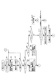
次に、この実施例におけるデジタルスチルカメラの動作概念を図6〜図8に示すフローチャートを参照して説明する。ここで、これらのフローチャートに記述されている各機能は、読み取り可能なプログラムコードの形態で格納されており、このプログラムコードにしたがった動作が逐次実行される。また、伝送媒体を介して伝送されてきた上述のプログラムコードに従った動作を逐次実行することもできる。すなわち、記録媒体の他に、伝送媒体を介して外部供給されたプログラム/データを利用してこの実施例特有の動作を実行することもできる。 Next, the operation concept of the digital still camera in this embodiment will be described with reference to the flowcharts shown in FIGS. Here, each function described in these flowcharts is stored in the form of a readable program code, and operations according to the program code are sequentially executed. In addition, the operation according to the above-described program code transmitted via the transmission medium can be sequentially executed. In other words, in addition to the recording medium, the program / data supplied externally via the transmission medium can be used to execute the operation specific to this embodiment.
図6〜図8は、撮影スイッチがオン操作された際に実行開始されるデジタルスチルカメラの全体動作を示したフローチャートである。
先ず、CPU1は、撮影スイッチがオン操作されると、ノーマルモードに初期設定した後(ステップS1)、カメラ撮影部7からモニタ画像を取得して画像メモリ8にセットすると共に(ステップS2)、モニタ画面に表示出力させる(ステップS3)。ここで、ボタン操作の有無をチェックし(ステップS4)、何らかのボタンが操作されるまでステップS2に戻って待機状態となるが、ボタン操作を検出した際には、操作ボタンの種類を判別し、モードボタンMDが操作されたか(ステップS5)、ズームボタンWDが操作されたか(ステップS6)、シャッターボタンかその他のボタンが操作されたかを調べる(ステップS7)。
6 to 8 are flowcharts showing the entire operation of the digital still camera that is started when the shooting switch is turned on.
First, when the photographing switch is turned on, the
いま、初期設定時のノーマルモードにおいて、ズームボタンWDが操作された際には(ステップS6でYES)、そのズームイン/ズームアウト操作に応じて光学ズームの駆動を制御する(ステップS9)。また、シャッターボタンが操作された際には(ステップS7でYES)、ノーマルモードにセットされていることを条件に(ステップS10)、シャッター操作時の撮影画像を画像メモリ8から取得して直交変換方式(離散コサイン変換方式)に従ってデータ圧縮を行った後(ステップS11)、この圧縮画像を記録メディア4に記録保存させる通常の動作を行う(ステップS12)。なお、ノーマルモードにおいて、その他のボタンが操作された際には(ステップS7でNO)、操作ボタンに応じた他の処理を実行した後(ステップS13)、モニタ画像の取得処理に戻る(ステップS2)。
If the zoom button WD is operated in the normal mode at the initial setting (YES in step S6), the optical zoom drive is controlled in accordance with the zoom-in / zoom-out operation (step S9). When the shutter button is operated (YES in step S7), the captured image at the time of the shutter operation is acquired from the
また、モードボタンMDが操作された場合には(ステップS5でYES)、モードボタンMDが操作される毎に、ノーマルモード/書画モード/書画・加工モードにサイクリックに切り換えるモード変更処理が行われる(ステップS8)。すなわち、ノーマルモードにセットされている場合には書画モードへの切り換えが行われ、書画モードにセットされている場合には書画・加工モードへの切り換えが行われ、書画・加工モードにセットされている場合にはノーマルモードへの切り換えが行われる。いま、ノーマルモードから書画モードに切り換えられた状態において、シャッターボタンが操作された際には、ステップS7、S10でそのことが判別されて図7のステップS15〜S26の実行に移り、書画情報を最適な状態で撮影可能とするために光学系の自動調整が行われる。 When the mode button MD is operated (YES in step S5), a mode change process for cyclically switching to the normal mode / document mode / document / processing mode is performed every time the mode button MD is operated. (Step S8). In other words, when the normal mode is set, the document mode is switched. When the document mode is set, the document / processing mode is switched and the document / processing mode is set. If so, switching to normal mode is performed. Now, when the shutter button is operated in the state where the mode is switched from the normal mode to the document mode, it is determined in steps S7 and S10, and the process proceeds to the execution of steps S15 to S26 in FIG. Automatic adjustment of the optical system is performed to enable photographing in an optimum state.
すなわち、画像メモリ8の領域内(モニタ画像枠内)において、このモニタ画像全体を解析することによって特定形状の画像部分(被写体部分)を書画領域として認識する (ステップS15)。この場合、予め設定されている書画領域の特徴情報、つまり、名刺、葉書き、カタログ、ホワイトボードなどの形状特性(例えば、四角形)を参照し、この特徴情報に一致する形状の画像部分が存在しているかをチェックし、有れば、その画像部分を書画領域として認識して書画領域の特定を行う。このようにして書画領域を特定すると、図3に示したように、書画領域の中心点を求めると共に、この書画領域の中心点とモニタ画像枠の原点とを比較することによって書画領域の偏り方向およびその偏り割合を求め(ステップS16)、この偏り割合が許容範囲内、つまり、書画領域がモニタ画像枠の中心部分にあるか否かをチェックすることによってモニタ画像に対して書画領域が最適な状態にあるか否かを判別する(ステップS17)。 That is, by analyzing the entire monitor image in the area of the image memory 8 (in the monitor image frame), an image part (subject part) having a specific shape is recognized as a document area (step S15). In this case, reference is made to the characteristic information of the document area that has been set in advance, that is, the shape characteristic (for example, quadrilateral) of the business card, postcard, catalog, whiteboard, etc., and there is an image part with a shape that matches this characteristic information If it exists, the image portion is recognized as a document region and the document region is specified. When the document area is specified in this way, as shown in FIG. 3, the center point of the document area is obtained, and the center point of the document area is compared with the origin of the monitor image frame to thereby determine the bias direction of the document area. The deviation ratio is obtained (step S16), and it is checked whether the deviation ratio is within an allowable range, that is, whether the drawing area is in the central portion of the monitor image frame. It is determined whether or not it is in a state (step S17).
ここで、書画領域の偏り割合が許容範囲内であれば(ステップS17でNO)、撮影レンズ71の向きを変更することなく、次のステップS20に移るが、偏り割合が許容範囲外であれば、撮影レンズ71の向きを自動調整する処理が行われる(ステップS18)。すなわち、書画領域の偏り方向およびその偏り割合に応じて撮影レンズ71の向きを駆動制御することによって撮影条件(撮影方向)を変更する。これによって書画領域がモニタ画像枠の中心部分に位置するようにその撮影方向の自動調整が行われる。そして、CPU1は、撮影方向を自動調整した直後のモニタ画像をカメラ撮影部7から取得して画像メモリ8にセットする(ステップS19)。
Here, if the deviation ratio of the document area is within the allowable range (NO in step S17), the process proceeds to the next step S20 without changing the orientation of the photographing
次に、モニタ画像枠に対して書画領域が最適な状態(最大サイズ)となるように光学ズームを自動調整する処理が行われる。すなわち、光学ズームの現在のセット状態をチェックし、ズームイン倍率がその最大値(例えば、光学4倍)未満であることを条件に(ステップS20)、光学ズームを1段階(例えば、0.5倍)だけズームイン駆動すると共に、フォーカス制御を行う(ステップS21)。これによって書画領域が拡大撮影されると、CPU1は、ズームイン直後のモニタ画像をカメラ撮影部7から取得して画像メモリ8にセットすると共に(ステップS22)、この画像メモリ8内の撮影画像を解析し、書画領域がモニタ画像枠から溢れたか(はみ出したか)否かをチェックし(ステップS23)、書画領域がモニタ画像枠内であれば(ステップS24でNO)、上述のステップS20に戻る。
Next, a process of automatically adjusting the optical zoom so that the document area is in an optimal state (maximum size) with respect to the monitor image frame is performed. That is, the current set state of the optical zoom is checked, and the optical zoom is performed only in one step (for example, 0.5 times) on condition that the zoom-in magnification is less than the maximum value (for example, optical 4 times) (step S20). In addition to zooming in, focus control is performed (step S21). When the document area is enlarged and photographed in this way, the
以下、ズームイン倍率がその最大値に達するか(ステップS20)、書画領域がモニタ画像枠から溢れるまで(ステップS24)、光学ズームを1段階毎にズームイン駆動しながら画像メモリ8の書き込み画像を順次更新してゆく。ここで、書画領域がモニタ画像枠から溢れる前にズームイン倍率がその最大値に達した場合には、図8のステップS31に移るが、ズームイン倍率がその最大値に達する前に書画領域がモニタ画像枠から溢れた場合には、1段階のズームアウト駆動を行うと共に(ステップS25)、ズームアウト直後の撮影画像をカメラ撮影部7から取得して画像メモリ8にセットした後(ステップS26)、図8のステップS31に移る。
Thereafter, until the zoom-in magnification reaches the maximum value (step S20) or until the document area overflows from the monitor image frame (step S24), the written image in the
図8のステップS31は、現在の動作モードを判別するもので、「書画モード」にセットされている場合には(ステップS31でNO)、その時点のモニタ画像を画像メモリ8から取得して直交変換方式に従ってデータ圧縮を行い(ステップS40)、この圧縮画像を記録メディア4に記録保存させた後(ステップS39)、図6のステップS2に戻ってモニタ画像の取得を行う。また、「書画・加工モード」にセットされている場合には、画像メモリ8から取得したモニタ画像をワークメモリ3(加工メモリ)にセットした後(ステップS32)、この加工メモリ内において、そのモニタ画像全体を解析しながら書画領域を特定して書画領域の抽出を行う(ステップS33)。
Step S31 in FIG. 8 is for determining the current operation mode. When the “document mode” is set (NO in step S31), the monitor image at that time is acquired from the
そして、CPU1は、抽出した書画領域に対して角度補正を施す(ステップS34)。例えば、長方形の名刺を撮影した際にその真上から撮影せず、斜め方向から撮影したものとすると、名刺の全体形状は、カメラ位置からの遠近差によって台形の状態で撮影されるが、このように書画領域が傾いて撮影された場合には、その傾きに応じて書画領域を回転させる角度補正を行う。図9(A)は、抽出した書画領域を示し、図9(B)は、角度補正後の画像を示している。次に、角度補正後の書画領域(台形)を元の方形(長方形)に補正する台形補正を施す(ステップS35)。この場合、台形の短辺(上辺に相当する部分)をその長辺(下辺に相当する部分)に合わせ込むために、書画領域を伸張して書画領域を元の方形(長方形)に補正する。図9(C)は、台形補正後の画像を示している。
Then, the
このようにして書画領域のフォルム最適化処理が実行されると、補正後の方形の書画領域内からノイズ除去と共に、所定の画像情報(例えば、文字などの画像情報)を抽出するフィルタリング処理を実行し(ステップS36)、更には、抽出した画像情報を鮮明に読み取れるようにその色合いを補正する色調補正処理を実行する(ステップS37)。このようにして得られた画像情報を直交変換方式に従ってデータ圧縮を行い(ステップS38)、この圧縮画像を記録メディア4に記録保存させた後(ステップS39)、図6のステップS2に戻ってモニタ画像の取得を行う。 When the form optimization process of the document area is executed in this way, a filtering process for extracting predetermined image information (for example, image information such as characters) is executed together with noise removal from the corrected rectangular document area. (Step S36), and further, a color tone correction process is performed to correct the hue so that the extracted image information can be read clearly (Step S37). The image information obtained in this way is subjected to data compression in accordance with the orthogonal transform method (step S38), the compressed image is recorded and stored in the recording medium 4 (step S39), and the process returns to step S2 in FIG. Acquire an image.
以上のように、この実施例のデジタルスチルカメラにおいてCPU1は、実際の撮影を行う前に撮影対象である書画情報をモニタ撮影したモニタ画像を取得した際、このモニタ画像を解析することによって書画情報が含まれている書画領域を特定すると共に、この書画領域が当該モニタ画像枠に対して所定の状態となるようにカメラ撮影部7の撮影制御部72を駆動制御して書画情報の撮影条件を変更するようにしたから、撮影対象である書画情報を撮影する際に、その撮影状態を慎重にマニュアル調整しなくても、書画情報を常に最適な状態で撮影することができ、撮影者の負担を大幅に軽減できる他、最適な状態で実撮影された画像に各種の補正を施す場合にその補正を正確に行うことが可能となる。
As described above, in the digital still camera of this embodiment, when the
ここで、ノーマルモードと書画モードとを切り換え可能としたから、必要に応じて通常撮影/書画撮影を任意に切り換えることが可能となり、書画カメラとしての専用カメラに限らず、一般の通常カメラとしても使用可能となる。この書画モードにおいて、CPU1は、書画情報が含まれている書画領域を特定する場合に、予め決められている書画領域の特徴情報を参照し、この特徴情報に該当する部分を書画領域として認識してその特定を行うようにしたから、例えば、名刺、葉書きなどの定型用紙、ホワイトボード、掲示板などの定型物を撮影したとしても、名刺、葉書き、ホワイトボードの撮影部分を書画領域として容易に特定することができる。
Here, since the normal mode and the document mode can be switched, it is possible to arbitrarily switch between normal shooting / document shooting as required, and not only a dedicated camera as a document camera but also a general normal camera. Can be used. In this document mode, when the
また、CPU1は、特定した書画領域がモニタ画像枠内の中心部分に位置するように、レンズの向きを駆動制御して撮影方向を変更するようにしたから、書画領域を常に適正な位置で撮影することが可能となる。更に、特定した書画領域がモニタ画像枠内に収まり、かつ、その枠サイズと同等となるように、光学ズームを駆動制御して撮影倍率を変更するようにしたから、常に最大倍率での撮影が可能となる。
In addition, since the
また、変更された撮影条件下で実撮影が行われた際に、CPU1は、この撮影画像を解析することによって特定された書画領域の全体が方形となるように、その形状を補正するフォルム最適化処理を実行した後、補正された書画領域内の画像を記録保存するようにしたから、歪みのない画像を記録保存することができる。更に、フォルム最適化処理を実行した後、このフォルム最適化処理によって補正された方形の書画領域内から所定の画像情報を抽出するフィルタリング処理を実行するようにしたから、ノイズを除去したり、文字などの所望する画像情報のみを記録保存することができる。
In addition, when actual shooting is performed under the changed shooting conditions, the
なお、上述した実施例においては、モニタ画像内の書画領域を特定する際に、予め設定されている名刺、葉書き、カタログ、ホワイトボードなどの形状特性(例えば、四角形)を参照し、この形状特性に一致する画像部分を書画領域として特定するようにしたが、形状特性に限らず、例えば、色特性、構成特性などを書画領域の特徴情報として設定するようにしてもよい。また、書画領域を特定する際に、形状特性と共に、その形状領域内に文字情報が含まれているか否かを判別するようにしたが、書画情報は、文字情報に限らず、記号、図形、写真等の画像等であってもよい。 In the above-described embodiment, when specifying the document area in the monitor image, reference is made to a preset shape characteristic (for example, a quadrangle) such as a business card, a postcard, a catalog, and a whiteboard. The image portion matching the characteristics is specified as the document area, but not limited to the shape characteristics, for example, color characteristics, composition characteristics, and the like may be set as the characteristic information of the document area. In addition, when specifying the document area, it is determined whether or not the character information is included in the shape area together with the shape characteristics. However, the document information is not limited to the character information, but includes symbols, figures, It may be an image such as a photograph.
上述した実施例においては、レンズの向きを駆動制御して撮影方向を自動変更したり、光学ズームを駆動制御して撮影倍率を自動変更するようにしたが、光学系の駆動制御としては、その他に、絞りを駆動制御して露出を自動変更するようにしてもよい。 In the above-described embodiments, the shooting direction is automatically changed by driving and controlling the lens direction, or the shooting magnification is automatically changed by driving and controlling the optical zoom. Further, the exposure may be automatically changed by driving the aperture.
上述した実施例においては、自動調整後の撮影条件下で実撮影された画像を記録保存する際に、書画領域内から抽出した画像のみを記録保存するようにしたが、自動調整後の撮影条件下で実撮影された撮影画像の全体を記録保存したり、この撮影画像から抽出した書画領域のみを記録保存するようにしてもよい。 In the above-described embodiment, when recording and saving an image actually taken under the shooting conditions after automatic adjustment, only the image extracted from the document area is recorded and saved. The entire photographed image actually taken below may be recorded and saved, or only the document area extracted from this photographed image may be recorded and saved.
また、上述した実施例においては、フォルム最適化処理を実行した後、このフォルム最適化処理によって補正された方形の書画領域内から所定の画像情報を抽出するフィルタリング処理を実行すると共に、抽出した画像情報を鮮明に読み取れるようにその色合いを補正する色調補正処理を実行したが、フィルタリング処理、色調補正処理は、カメラ側で行わず、パーソナルコンピュータなどの他の電子機器で行うようにしてもよい。 In the above-described embodiment, after performing the form optimization process, the filtering process for extracting predetermined image information from the rectangular document region corrected by the form optimization process is performed, and the extracted image Although the color tone correction processing for correcting the hue so that the information can be read clearly is executed, the filtering processing and the color tone correction processing may be performed not by the camera side but by other electronic devices such as a personal computer.
更に、上述した実施例においては、商談会、報告会、審議会などでの各種の資料、名刺、葉書き、カタログ、ホワイトボードなどを撮影対象とするビジネスミーティング用の携帯型書画カメラに適用した場合を示したが、プロジェクターのオプションとして、その書画台にアームを介して取り付けた書画カメラであってもよい。この場合、プロジェクターから書画カメラを取り外し可能として、ホワイトボードなどを撮影可能としてもよく、更には、ビジネスミーティング用に限らず、一般用など任意の用途にも適用可能であることは勿論である。 Furthermore, in the above-described embodiment, the present invention is applied to a portable document camera for a business meeting for photographing various materials, business cards, postcards, catalogs, whiteboards, etc. at business meetings, debriefings, and councils. Although the case has been shown, as a projector option, a document camera attached to the document table via an arm may be used. In this case, the document camera may be detachable from the projector, and a whiteboard or the like may be photographed. Furthermore, it is of course applicable not only for business meetings but also for general uses.
一方、コンピュータに対して、上述した各手段を実行させるためのプログラムコードをそれぞれ記録した記録媒体(例えば、CD−ROM、フレキシブルディスク、RAMカード等)を提供するようにしてもよい。すなわち、コンピュータが読み取り可能なプログラムコードを有する記録媒体であって、実際の撮影を行う前に撮影対象である書画情報を仮撮影した撮影画像を取得した際、この撮影画像を解析することによって書画情報が含まれている書画領域を特定する機能と、特定された書画領域が当該仮撮影した画像領域に対して所定の状態となるように、光学系を駆動制御して書画情報の撮影条件を変更する機能と、変更後の撮影条件下で実撮影された画像を記録保存する機能とを実現させるためのプログラムを記録したコンピュータが読み取り可能な記録媒体を提供するようにしてもよい。 On the other hand, a recording medium (for example, a CD-ROM, a flexible disk, a RAM card, etc.) on which program codes for executing the above-described units are recorded may be provided to the computer. That is, a recording medium having a program code that can be read by a computer, and when a photographed image obtained by temporarily photographing document information to be photographed before actual photographing is obtained, the document is analyzed by analyzing the photographed image. A function for specifying the document area including the information and the shooting condition of the document information by controlling the optical system so that the specified document area is in a predetermined state with respect to the temporarily captured image area. You may make it provide the computer-readable recording medium which recorded the program for implement | achieving the function to change and the function to record and preserve | save the image actually image | photographed on the imaging conditions after a change.
1 CPU
2 記憶部
4 記録メディア
5 操作部
6 表示部
7 カメラ撮影部
8 画像メモリ
72 撮影制御部
73 撮像処理部
ST シャッターボタン
MD モードボタン
1 CPU
2
Claims (8)
実際の撮影を行う前に撮影対象である書画情報を仮撮影した撮影画像を取得した際、この撮影画像を解析することによって書画情報が含まれている書画領域を特定する特定手段と、
この特定手段によって特定された書画領域が当該仮撮影した画像領域内の中心部分に位置するように、光学系を駆動制御して撮影方向を変更する制御手段と、
を具備し、前記変更後の撮影方向で実撮影された画像を記録保存するようにしたことを特徴とする電子カメラ。 An electronic camera that records and saves captured images of document information,
A specifying means for identifying a document area including document information by analyzing the photographed image when acquiring a photographed image obtained by temporarily photographing document information to be photographed before actual photographing;
Control means for driving and controlling the optical system so as to change the shooting direction so that the document area specified by the specifying means is positioned at the central portion in the temporarily shot image area ;
An electronic camera characterized in that an image actually taken in the changed shooting direction is recorded and stored.
ようにしたことを特徴とする請求項1記載の電子カメラ。 The specifying means, when specifying a document area including document information, refers to characteristic information of a predetermined document area and specifies a portion corresponding to the feature information as a document area.
The electronic camera according to claim 1, which is configured as described above.
ようにしたことを特徴とする請求項1〜3の何れかに記載の電子カメラ。 The control means further drives and controls the optical system to change the photographing magnification so that the specified document area falls within the temporary photographing image area and is equal to the area size.
The electronic camera according to claim 1, which is configured as described above.
前記書画撮影モードに切り換えられている状態において、書画情報を仮撮影した撮影画像内の書画領域を特定すると共に、この書画領域が当該仮撮影した画像領域内の中心部分に位置するように、光学系を駆動制御して撮影方向を変更する、
ようにしたことを特徴とする請求項1〜4の何れかに記載の電子カメラ。 A mode switching means is provided for arbitrarily switching between a document shooting mode for shooting document information and a normal shooting mode for shooting an arbitrary subject,
In the state of switching to the document shooting mode, the document area in the captured image obtained by temporarily capturing the document information is specified, and the document area is positioned in the central portion in the temporarily captured image area. Change the shooting direction by driving the system,
The electronic camera according to claim 1, which is configured as described above.
この補正処理手段によって形状補正された書画領域内の画像を記録保存する、
ようにしたことを特徴とする請求項1〜5の何れかに記載の電子カメラ。 A correction processing unit is provided to correct the shape of the document area specified by analyzing the captured image when the actual shooting is performed in the shooting direction changed by the control unit,
Recording and saving an image in the document area whose shape has been corrected by the correction processing means;
The electronic camera according to claim 1, wherein the electronic camera is configured as described above.
ようにしたことを特徴とする請求項6記載の電子カメラ。 The correction processing means executes a form optimization process for correcting the shape of the specified document area so that the whole of the specified document area becomes a square, and then, from within the rectangular document area corrected by the form optimization process. Executing a filtering process for extracting predetermined image information;
The electronic camera according to claim 6, which is configured as described above.
実際の撮影を行う前に撮影対象である書画情報を仮撮影した撮影画像を取得した際、この撮影画像を解析することによって書画情報が含まれている書画領域を特定する機能と、
特定された書画領域が当該仮撮影した画像領域内の中心部分に位置するように、光学系を駆動制御して撮影方向を変更する機能と、
変更後の撮影方向で実撮影された画像を記録保存する機能と、
を実現させるためのプログラム。 Against the computer,
A function for identifying a document area including document information by analyzing the photographed image when acquiring a photographed image obtained by temporarily photographing document information to be photographed before actual photographing;
A function of changing the shooting direction by driving and controlling the optical system so that the specified document area is located at the center of the temporarily shot image area ;
A function to record and save images actually shot in the changed shooting direction ;
A program to realize
Priority Applications (5)
| Application Number | Priority Date | Filing Date | Title |
|---|---|---|---|
| JP2004129218A JP4337614B2 (en) | 2004-04-26 | 2004-04-26 | Electronic camera and program |
| US11/109,040 US8139118B2 (en) | 2004-04-26 | 2005-04-18 | Optimal-state image pickup camera |
| EP05290880A EP1592234A3 (en) | 2004-04-26 | 2005-04-20 | Optimal-state image pickup device |
| KR1020050033883A KR100664565B1 (en) | 2004-04-26 | 2005-04-25 | Digital camera |
| CNB2005100662559A CN100382572C (en) | 2004-04-26 | 2005-04-25 | Numeral camera |
Applications Claiming Priority (1)
| Application Number | Priority Date | Filing Date | Title |
|---|---|---|---|
| JP2004129218A JP4337614B2 (en) | 2004-04-26 | 2004-04-26 | Electronic camera and program |
Publications (2)
| Publication Number | Publication Date |
|---|---|
| JP2005311926A JP2005311926A (en) | 2005-11-04 |
| JP4337614B2 true JP4337614B2 (en) | 2009-09-30 |
Family
ID=34942177
Family Applications (1)
| Application Number | Title | Priority Date | Filing Date |
|---|---|---|---|
| JP2004129218A Expired - Fee Related JP4337614B2 (en) | 2004-04-26 | 2004-04-26 | Electronic camera and program |
Country Status (5)
| Country | Link |
|---|---|
| US (1) | US8139118B2 (en) |
| EP (1) | EP1592234A3 (en) |
| JP (1) | JP4337614B2 (en) |
| KR (1) | KR100664565B1 (en) |
| CN (1) | CN100382572C (en) |
Families Citing this family (9)
| Publication number | Priority date | Publication date | Assignee | Title |
|---|---|---|---|---|
| EP1941726A4 (en) * | 2004-08-30 | 2008-09-17 | Trace Optic Technologies Pty L | A method and apparatus of camera control |
| US7812994B2 (en) * | 2005-06-10 | 2010-10-12 | Marvell International Technology Ltd. | Handheld printer |
| JP2011028345A (en) * | 2009-07-22 | 2011-02-10 | Olympus Imaging Corp | Condition change device, camera, mobile apparatus and program |
| US9516271B2 (en) | 2012-10-31 | 2016-12-06 | Microsoft Technology Licensing, Llc | Auto-adjusting content size rendered on a display |
| JP6034486B2 (en) * | 2013-04-10 | 2016-11-30 | 株式会社東芝 | Electronics |
| JP6307942B2 (en) | 2014-03-05 | 2018-04-11 | セイコーエプソン株式会社 | IMAGING DEVICE AND IMAGING DEVICE CONTROL METHOD |
| JP6759018B2 (en) * | 2016-09-06 | 2020-09-23 | キヤノン株式会社 | Imaging device and exposure control method |
| CN109254663B (en) * | 2018-09-07 | 2021-04-09 | 许昌特博特科技有限公司 | Using method of auxiliary reading robot for books of children |
| CN111970437B (en) * | 2020-08-03 | 2022-08-09 | 广东小天才科技有限公司 | Text shooting method, wearable device and storage medium |
Family Cites Families (52)
| Publication number | Priority date | Publication date | Assignee | Title |
|---|---|---|---|---|
| JPS62195970A (en) | 1986-02-21 | 1987-08-29 | Mitsubishi Electric Corp | Electronic blackboard device |
| JP3125340B2 (en) * | 1991-07-29 | 2001-01-15 | 富士写真フイルム株式会社 | Film image input device |
| US5631697A (en) * | 1991-11-27 | 1997-05-20 | Hitachi, Ltd. | Video camera capable of automatic target tracking |
| US5266805A (en) * | 1992-05-05 | 1993-11-30 | International Business Machines Corporation | System and method for image recovery |
| JPH06113187A (en) * | 1992-09-25 | 1994-04-22 | Sony Corp | Automatic focusing camera device |
| JPH06233065A (en) * | 1993-02-06 | 1994-08-19 | Nikon Corp | Picture and calligraphic work input device |
| JP3372299B2 (en) | 1993-05-20 | 2003-01-27 | 富士写真フイルム株式会社 | Camera system, photometric method, and imaging control device |
| US6236431B1 (en) | 1993-05-27 | 2001-05-22 | Canon Kabushiki Kaisha | Video camera apparatus with distance measurement area adjusted based on electronic magnification |
| JPH0793510A (en) * | 1993-09-21 | 1995-04-07 | Nippon Telegr & Teleph Corp <Ntt> | Object sighting image pickup device |
| SG67927A1 (en) | 1993-10-20 | 1999-10-19 | Videoconferencing Sys Inc | Adaptive videoconferencing system |
| JPH07234447A (en) | 1993-12-28 | 1995-09-05 | Canon Inc | Photographic unit and camera |
| JPH08125915A (en) * | 1994-10-24 | 1996-05-17 | Casio Comput Co Ltd | Method for automatically adjusting resolution of image pickup element |
| JP2981408B2 (en) * | 1995-02-16 | 1999-11-22 | 日本電気システム建設株式会社 | Method and apparatus for controlling high-speed introduction of a target object in a camera image |
| US6445416B1 (en) * | 1995-06-30 | 2002-09-03 | Canon Kabushiki Kaisha | Image pickup apparatus having electronic zoom function based on optical zooming focal length variation with time |
| DE19645716A1 (en) * | 1995-11-06 | 1997-05-07 | Ricoh Kk | Digital individual image camera with image data transaction function |
| JP3608288B2 (en) * | 1996-04-19 | 2005-01-05 | 株式会社富士通ゼネラル | Surveillance camera system |
| GB9614837D0 (en) * | 1996-07-12 | 1996-09-04 | Rank Xerox Ltd | Interactive desktop system with multiple image capture and display modes |
| JPH10229515A (en) | 1997-02-13 | 1998-08-25 | Toshiba Corp | Document camera |
| JPH10313424A (en) | 1997-05-12 | 1998-11-24 | Minolta Co Ltd | Image pickup device |
| JP2899263B2 (en) * | 1997-10-20 | 1999-06-02 | キヤノン株式会社 | Computer control method |
| JP3186696B2 (en) * | 1998-05-28 | 2001-07-11 | 日本電気株式会社 | Optical symbol reader |
| CN1210944C (en) * | 1998-10-02 | 2005-07-13 | 旺宏电子股份有限公司 | Method and device for preventing keystone distortion |
| WO2001015086A1 (en) * | 1999-08-19 | 2001-03-01 | Sony Corporation | Image processor, image processing method, and recorded medium |
| US6753907B1 (en) * | 1999-12-23 | 2004-06-22 | Justsystem Corporation | Method and apparatus for automatic keystone correction |
| US7151562B1 (en) * | 2000-08-03 | 2006-12-19 | Koninklijke Philips Electronics N.V. | Method and apparatus for external calibration of a camera via a graphical user interface |
| JP3429280B2 (en) * | 2000-09-05 | 2003-07-22 | 理化学研究所 | How to correct lens distortion in images |
| US6584433B1 (en) * | 2000-10-04 | 2003-06-24 | Hewlett-Packard Development Company Lp | Harmonic average based clustering method and system |
| US6963365B2 (en) | 2001-02-28 | 2005-11-08 | Hewlett-Packard Development Company, L.P. | System and method for removal of digital image vertical distortion |
| JP4366023B2 (en) * | 2001-03-16 | 2009-11-18 | インターナショナル・ビジネス・マシーンズ・コーポレーション | Partial image region extraction method of video image, partial image region extraction system, program for extracting partial image region, distribution method of extracted video image, and content creation method |
| JP2002354331A (en) * | 2001-05-25 | 2002-12-06 | Canon Inc | Imaging equipment and electronic component |
| US6574433B1 (en) * | 2001-06-08 | 2003-06-03 | Frank Stuempfl | Underwater camera housing |
| GB2378340A (en) * | 2001-07-31 | 2003-02-05 | Hewlett Packard Co | Generation of an image bounded by a frame or of overlapping images |
| GB2378341B (en) * | 2001-07-31 | 2005-08-24 | Hewlett Packard Co | Improvements in and relating to dislaying digital images |
| JP2003058877A (en) | 2001-08-20 | 2003-02-28 | Pfu Ltd | Method, device and program for correcting distortion |
| JP3666429B2 (en) * | 2001-09-03 | 2005-06-29 | コニカミノルタフォトイメージング株式会社 | Autofocus device and method, and camera |
| US7356763B2 (en) * | 2001-09-13 | 2008-04-08 | Hewlett-Packard Development Company, L.P. | Real-time slide presentation multimedia data object and system and method of recording and browsing a multimedia data object |
| US7042488B2 (en) * | 2001-09-27 | 2006-05-09 | Fujinon Corporation | Electronic endoscope for highlighting blood vessel |
| US7301569B2 (en) * | 2001-09-28 | 2007-11-27 | Fujifilm Corporation | Image identifying apparatus and method, order processing apparatus, and photographing system and method |
| JP3849517B2 (en) * | 2001-12-14 | 2006-11-22 | ソニー株式会社 | Photo booth, image processing method, recording medium, and program |
| US7260259B2 (en) * | 2002-01-08 | 2007-08-21 | Siemens Medical Solutions Usa, Inc. | Image segmentation using statistical clustering with saddle point detection |
| JP2003283909A (en) | 2002-03-20 | 2003-10-03 | Ricoh Co Ltd | Color image photographing apparatus with name card intake function |
| JP2004053686A (en) | 2002-07-16 | 2004-02-19 | Olympus Corp | Method for controlling camera and focusing device |
| CN100510943C (en) * | 2003-01-08 | 2009-07-08 | 奥普提克斯晶硅有限公司 | Image projection system and method |
| JP2004287699A (en) * | 2003-03-20 | 2004-10-14 | Tama Tlo Kk | Image composition device and method |
| JP2004320123A (en) * | 2003-04-11 | 2004-11-11 | Nec Viewtechnology Ltd | Data presentation apparatus |
| JP2004326547A (en) * | 2003-04-25 | 2004-11-18 | Nippon Conlux Co Ltd | Method and apparatus for identifying sheet of paper |
| JP3620537B2 (en) * | 2003-05-02 | 2005-02-16 | セイコーエプソン株式会社 | Image processing system, projector, program, information storage medium, and image processing method |
| US20050041111A1 (en) * | 2003-07-31 | 2005-02-24 | Miki Matsuoka | Frame adjustment device and image-taking device and printing device |
| US7454040B2 (en) * | 2003-08-29 | 2008-11-18 | Hewlett-Packard Development Company, L.P. | Systems and methods of detecting and correcting redeye in an image suitable for embedded applications |
| JP2005130390A (en) * | 2003-10-27 | 2005-05-19 | Anritsu Corp | Display screen control apparatus and remote monitoring apparatus using the same |
| US20050134719A1 (en) * | 2003-12-23 | 2005-06-23 | Eastman Kodak Company | Display device with automatic area of importance display |
| US7386150B2 (en) * | 2004-11-12 | 2008-06-10 | Safeview, Inc. | Active subject imaging with body identification |
-
2004
- 2004-04-26 JP JP2004129218A patent/JP4337614B2/en not_active Expired - Fee Related
-
2005
- 2005-04-18 US US11/109,040 patent/US8139118B2/en not_active Expired - Fee Related
- 2005-04-20 EP EP05290880A patent/EP1592234A3/en not_active Withdrawn
- 2005-04-25 CN CNB2005100662559A patent/CN100382572C/en not_active Expired - Fee Related
- 2005-04-25 KR KR1020050033883A patent/KR100664565B1/en active IP Right Grant
Also Published As
| Publication number | Publication date |
|---|---|
| CN100382572C (en) | 2008-04-16 |
| EP1592234A2 (en) | 2005-11-02 |
| EP1592234A3 (en) | 2008-02-13 |
| KR20060045819A (en) | 2006-05-17 |
| CN1691753A (en) | 2005-11-02 |
| KR100664565B1 (en) | 2007-01-04 |
| JP2005311926A (en) | 2005-11-04 |
| US8139118B2 (en) | 2012-03-20 |
| US20050237392A1 (en) | 2005-10-27 |
Similar Documents
| Publication | Publication Date | Title |
|---|---|---|
| JP4761146B2 (en) | Imaging apparatus and program thereof | |
| US6806906B1 (en) | Digital still camera with composition assist function, and method of controlling operation of same | |
| KR100664565B1 (en) | Digital camera | |
| JP4233624B2 (en) | Electronic camera device | |
| JP2006217074A (en) | Imaging device and its program | |
| JP4380644B2 (en) | Electronic camera device | |
| JPH09149311A (en) | Image pickup device | |
| JP4848230B2 (en) | Image processing method, imaging apparatus, image processing apparatus, and program | |
| JP5013282B2 (en) | Imaging apparatus and program | |
| JP2004239967A (en) | Projector | |
| JP4717867B2 (en) | Imaging apparatus and imaging method | |
| JP4978724B2 (en) | Imaging apparatus and program | |
| US7714899B2 (en) | Image pickup camera and program for picking up-an optimal-state image of a print/picture | |
| JP4254604B2 (en) | Electronic camera and program | |
| JP2006203732A (en) | Digital camera, portrait/landscape aspect photographing switching method and program | |
| JP4232682B2 (en) | Electronic camera and program | |
| JP2004013461A (en) | Image processing system and digital imaging apparatus | |
| JP2004023632A (en) | Digital camera | |
| JP5077113B2 (en) | Electronic camera | |
| JP2012053521A (en) | Image edition processing device, image edition processing program and digital camera with projector | |
| JP2009265583A (en) | Photographing device | |
| JP2004023631A (en) | Digital camera | |
| JP2009141703A (en) | Imaging apparatus, and control method and program therefor | |
| JP2006025092A (en) | Photographing apparatus | |
| JP2001094859A (en) | Image pickup device, its method and computer readable storage medium |
Legal Events
| Date | Code | Title | Description |
|---|---|---|---|
| RD02 | Notification of acceptance of power of attorney |
Free format text: JAPANESE INTERMEDIATE CODE: A7422 Effective date: 20060209 |
|
| RD04 | Notification of resignation of power of attorney |
Free format text: JAPANESE INTERMEDIATE CODE: A7424 Effective date: 20060314 |
|
| A621 | Written request for application examination |
Free format text: JAPANESE INTERMEDIATE CODE: A621 Effective date: 20061106 |
|
| RD04 | Notification of resignation of power of attorney |
Free format text: JAPANESE INTERMEDIATE CODE: A7424 Effective date: 20080519 |
|
| A131 | Notification of reasons for refusal |
Free format text: JAPANESE INTERMEDIATE CODE: A131 Effective date: 20081216 |
|
| A521 | Request for written amendment filed |
Free format text: JAPANESE INTERMEDIATE CODE: A523 Effective date: 20090129 |
|
| TRDD | Decision of grant or rejection written | ||
| A01 | Written decision to grant a patent or to grant a registration (utility model) |
Free format text: JAPANESE INTERMEDIATE CODE: A01 Effective date: 20090609 |
|
| A01 | Written decision to grant a patent or to grant a registration (utility model) |
Free format text: JAPANESE INTERMEDIATE CODE: A01 |
|
| A61 | First payment of annual fees (during grant procedure) |
Free format text: JAPANESE INTERMEDIATE CODE: A61 Effective date: 20090622 |
|
| R150 | Certificate of patent or registration of utility model |
Free format text: JAPANESE INTERMEDIATE CODE: R150 |
|
| FPAY | Renewal fee payment (event date is renewal date of database) |
Free format text: PAYMENT UNTIL: 20120710 Year of fee payment: 3 |
|
| FPAY | Renewal fee payment (event date is renewal date of database) |
Free format text: PAYMENT UNTIL: 20120710 Year of fee payment: 3 |
|
| FPAY | Renewal fee payment (event date is renewal date of database) |
Free format text: PAYMENT UNTIL: 20130710 Year of fee payment: 4 |
|
| LAPS | Cancellation because of no payment of annual fees |