JP4174208B2 - Information processing terminal and information processing method - Google Patents
Information processing terminal and information processing method Download PDFInfo
- Publication number
- JP4174208B2 JP4174208B2 JP2001368271A JP2001368271A JP4174208B2 JP 4174208 B2 JP4174208 B2 JP 4174208B2 JP 2001368271 A JP2001368271 A JP 2001368271A JP 2001368271 A JP2001368271 A JP 2001368271A JP 4174208 B2 JP4174208 B2 JP 4174208B2
- Authority
- JP
- Japan
- Prior art keywords
- information processing
- information
- device address
- address
- processing terminal
- Prior art date
- Legal status (The legal status is an assumption and is not a legal conclusion. Google has not performed a legal analysis and makes no representation as to the accuracy of the status listed.)
- Expired - Fee Related
Links
Images


Classifications
-
- G—PHYSICS
- G06—COMPUTING; CALCULATING OR COUNTING
- G06K—GRAPHICAL DATA READING; PRESENTATION OF DATA; RECORD CARRIERS; HANDLING RECORD CARRIERS
- G06K7/00—Methods or arrangements for sensing record carriers, e.g. for reading patterns
- G06K7/10—Methods or arrangements for sensing record carriers, e.g. for reading patterns by electromagnetic radiation, e.g. optical sensing; by corpuscular radiation
- G06K7/10544—Methods or arrangements for sensing record carriers, e.g. for reading patterns by electromagnetic radiation, e.g. optical sensing; by corpuscular radiation by scanning of the records by radiation in the optical part of the electromagnetic spectrum
- G06K7/10821—Methods or arrangements for sensing record carriers, e.g. for reading patterns by electromagnetic radiation, e.g. optical sensing; by corpuscular radiation by scanning of the records by radiation in the optical part of the electromagnetic spectrum further details of bar or optical code scanning devices
- G06K7/1095—Methods or arrangements for sensing record carriers, e.g. for reading patterns by electromagnetic radiation, e.g. optical sensing; by corpuscular radiation by scanning of the records by radiation in the optical part of the electromagnetic spectrum further details of bar or optical code scanning devices the scanner comprising adaptations for scanning a record carrier that is displayed on a display-screen or the like
Landscapes
- Physics & Mathematics (AREA)
- Engineering & Computer Science (AREA)
- Electromagnetism (AREA)
- Artificial Intelligence (AREA)
- Toxicology (AREA)
- General Health & Medical Sciences (AREA)
- Health & Medical Sciences (AREA)
- Computer Vision & Pattern Recognition (AREA)
- General Physics & Mathematics (AREA)
- Theoretical Computer Science (AREA)
- Facsimiles In General (AREA)
- Studio Devices (AREA)
- Telephone Function (AREA)
Description
【0001】
【発明の属する技術分野】
この発明は、送信対象となる目的の機器を一意に特定する情報を取得することによって、目的の機器との間に無線通信ネットワークを形成する情報処理端末および情報処理方法に関する。
【0002】
【従来の技術】
限られたエリア内において複数の機器の間で通信を行う場合の一つの方法として、複数の機器の間にBluetoothによる無線通信ネットワークを形成する方法が考えられている。
【0003】
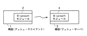
Bluetoothでは、各機器に‘Bluetooth Device Address’が割り当てられ、図8に示すように、それぞれBluetoothモジュール2,4を備える機器1,3間に、機器1をプッシュ・クライアント(送信側デバイス)とし、機器3をプッシュ・サーバ(受信側デバイス)とする無線通信ネットワークを形成するに当たっては、機器1において機器3の‘Bluetooth Device Address’を取得する必要がある。
【0004】
‘Bluetooth Device Address’は、Bluetooth機器を一意に特定する情報で、‘00:0C:3E:3A:4B:69’または‘000C3E3A4B69’などのように、12文字の16進の英数字で表記される総計48ビット(6バイト)のアドレスである。以下、‘Bluetooth Device Address’をデバイスアドレスと称する。
【0005】
Bluetooth機器には、デバイスアドレス以外に、‘Bluetooth Device Name’や‘Class of Device’を付すことができる。‘Bluetooth Device Name’は、‘VAIO(登録商標)C1’などのような、機器の名前を示し、‘Class of Device’は、‘PC’や‘PDA’などのような、機器のカテゴリー名や機器の提供するサービス名などを示す。以下、‘Bluetooth Device Name’をデバイスネームと称し、‘Class of Device’をデバイスカテゴリーと称する。
【0006】
機器1において機器3のデバイスアドレスを取得したら、機器1は、接続フェーズによって、機器3に接続して、機器3に情報を送信することができる。
【0007】
機器1において機器3のデバイスアドレスを取得する方法としては、従来、図9に示すような方法が用いられている。
【0008】
図9のデバイスアドレス取得処理ルーチンでは、機器1のCPUは、まずステップ91で、機器を探索する。この機器探索は、機器1から周辺の機器にデバイスアドレスを送信することを要求し、これに応答して周辺の機器が自己のデバイスアドレスを送信することによって実行される。
【0009】
次に、機器1のCPUは、ステップ92で、周辺の機器のデバイスアドレスを取得し、さらにステップ93で、デバイスアドレスを送信した機器にデバイスネームを送信することを要求し、さらにステップ94で、デバイスアドレスを送信した機器のデバイスネームを取得する。
【0010】
次に、機器1のCPUは、ステップ95で、機器1のディスプレイ上に、取得したデバイスアドレスおよびデバイスネームを表示する。ユーザは、目的の機器3のデバイスアドレスが取得されたときには、それを選択して探索を終了させる操作を行い、目的の機器3のデバイスアドレスが取得されなかったときには、探索を続行させる操作を行う。
【0011】
次に、機器1のCPUは、ステップ96で、ユーザの操作から、目的の機器のデバイスアドレスを取得したか否かを判断し、取得していなければ、ステップ96からステップ91に戻って、機器探索を続行し、取得したときには、ステップ96からステップ97に進んで、目的の機器のデバイスアドレスを決定し、機器1内に登録する。
【0012】
このように機器1において機器3のデバイスアドレスを取得することにより、機器1,3間に無線通信ネットワークが形成され、以後、機器1は、接続フェーズによって、機器3に接続して、機器3に情報を送信することができる。
【0013】
【発明が解決しようとする課題】
しかしながら、上述した従来の方法では、1回の機器探索に10〜30秒程度の時間がかかるだけでなく、機器1の周辺に目的の機器3以外に幾つかのBluetooth機器が存在する場合、目的の機器3が見つからず、デバイスアドレスを取得できなかったり、デバイスアドレスを取得できたとしても、デバイスネームを取得できなかったりすることもあり、その場合には機器探索を何回も繰り返さなければならないので、目的の機器3のデバイスアドレスおよびデバイスネームを取得するのに長い時間がかかるとともに、ユーザは探索の都度、機器1に対して指示しなければならない煩わしさがある。
【0014】
機器1が英数字列の入力機能を備える場合には、機器1に直接、機器3のデバイスアドレスを入力することもできるが、機器1が英数字列の入力機能を持たない場合には、機器1に直接、機器3のデバイスアドレスを入力することはできない。また、機器1が英数字列の入力機能を備える場合でも、機器1に直接、英数字列を入力するのは、ユーザにとって煩わしく、入力ミスも生じやすい。
【0015】
そこで、この発明は、送信対象となる目的の機器のデバイスアドレス(機器を一意に特定する情報をデバイスアドレスと定義する)を取得することによって、目的の機器との間に無線通信ネットワークを形成する情報処理端末において、目的の機器のデバイスアドレスを短時間で確実に取得することができるようにしたものである。
【0016】
【課題を解決するための手段】
第1の発明の情報処理端末は、
撮像した画像を画像情報として出力する撮像部と、
この撮像部から出力された画像情報から、送信対象となる機器を一意に特定するデバイスアドレス情報を示すバーコードを認識し、上記機器のデバイスアドレスを取得する制御部と、
この制御部で取得されたデバイスアドレスによって特定された機器に情報を無線で送信する無線送信部とを備え、
上記バーコードは、送信対象となる機器のディスプレイ上に表示され、上記撮像部によって撮像されて上記画像情報として出力されたものである、
ことを特徴とする。
【0017】
第2の発明の情報処理端末は、
画像情報を取り込むインタフェース部と、
このインタフェース部から取り込まれた画像情報から、送信対象となる機器を一意に特定するデバイスアドレス情報を示すバーコードを認識し、上記機器のデバイスアドレスを取得する制御部と、
この制御部で取得されたデバイスアドレスによって特定された機器に情報を無線で送信する無線送信部とを備え、
上記バーコードは、送信対象となる機器のディスプレイ上に表示され、カメラによって撮像されて、上記インタフェース部から上記画像情報として取り込まれたものである、
ことを特徴とする。
【0018】
上記のように構成した、この発明の情報処理端末では、当該情報処理端末が備える撮像部、または当該情報処理端末に接続されたカメラ(撮像部)によって、送信対象となる目的の機器のディスプレイ上に表示された、送信対象となる目的の機器のデバイスアドレス情報が表されたバーコードを撮影するだけで、目的の機器のデバイスアドレスを取得することができ、目的の機器のデバイスアドレスを短時間で確実に取得することができる。
【0019】
【発明の実施の形態】
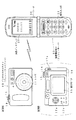
図1は、この発明の無線通信システムの一実施形態を示し、Bluetoothのプッシュ・クライアントとしてのデジタルスチルカメラ10と、Bluetoothのプッシュ・サーバとしての携帯電話端末30とによって、無線通信システムを構成し、デジタルスチルカメラ10において携帯電話端末30のデバイスアドレスを取得することによって、デジタルスチルカメラ10と携帯電話端末30との間にBluetoothによる無線通信ネットワークを形成する場合である。
【0020】
デジタルスチルカメラ10は、正面側に、レンズ11などを備え、レンズ11の内側に、CCD(Charge Coupled Device)を備え、上面側に、モードスイッチ13およびシャッタースイッチ14などを備え、背面側に、液晶モニタ15、バッテリとメモリカードの収納室16、十字キー17a、ダイレクトボタン17bおよびジョグダイヤル17cなどを備えるとともに、プッシュ・クライアントとしてBluetooth機能を搭載したものである。
【0021】
携帯電話端末30は、各種の操作キーおよび文字入力キーからなる操作入力部31、および表示部としての液晶ディスプレイ32などを備えるとともに、プッシュ・サーバとしてBluetooth機能を搭載したものである。
【0022】
図2は、デジタルスチルカメラ10の機能ブロック構成を示す。以下、デジタルスチルカメラ10を、カメラ10と称する。
【0023】
通常の撮像モードまたは後述のデバイスアドレス取得モードにおいて、図1に示したシャッタースイッチ14が押されることによって、レンズ11を介してCCD12に光が照射され、画像が撮影される。その画像は、読み出し処理部21によって画像データとして出力され、システムバス22に送出される。
【0024】
システムバス22には、CPU23、CPU23が実行すべき後述のデバイスアドレス取得処理ルーチンなどを含むプログラムや、カメラ10のデバイスアドレスなどの固定情報が書き込まれたROM24、CPU23のワークエリアなどとして機能するDRAM25、画像ファイル記録用のフラッシュメモリ26、図1に示した液晶モニタ15、図1に示したモードスイッチ13、シャッタースイッチ14、十字キー17a、ダイレクトボタン17bおよびジョグダイヤル17cなどからなる操作部18が接続される。さらに、システムバス22には、USB(Universal Serial Bus)インタフェース28を介してBluetoothモジュール29が接続される。
【0025】
フラッシュメモリ26は、メモリカード27として構成され、図1に示した収納室16に装着される。
【0026】
通常の撮像モードで読み出し処理部21からシステムバス22に出力された画像データは、CPU23によって、JPEG(Joint Photographic Experts Group)圧縮され、所定フォーマットの画像ファイルとして、フラッシュメモリ26に書き込まれる。
【0027】
後述のデバイスアドレス取得モードで読み出し処理部21からシステムバス22に出力された画像データは、CPU23によって、DRAM25に書き込まれた後、後述のように処理される。
【0028】
さらに、後述のように、カメラ10で得られた画像データが、Bluetoothの通信用のオブジェクト・プッシュ・プロファイルとして、カメラ10でのオブジェクト・プッシュ操作によって、USBインタフェース28を介してBluetoothモジュール29から、図1の携帯電話端末30に送信される。
【0029】
携帯電話端末30は、待ち受けモードにおいて、または操作入力部31でデバイスアドレスを呼び出す操作をすることによって、液晶ディスプレイ32上に、携帯電話端末30のデバイスアドレスを示す画像として、バーコード35が表示される。
【0030】
具体的に、バーコード35は、携帯電話端末30のデバイスアドレスに誤り訂正符号を付加したものを示したものとし、または携帯電話端末30のデバイスアドレスおよびデバイスネームまたはデバイスカテゴリーにそれぞれ誤り訂正符号を付加したものを示したものとする。
【0031】
ユーザは、カメラ10に携帯電話端末30のデバイスアドレスを取得させて、カメラ10と携帯電話端末30との間にBluetoothによる無線通信ネットワークを形成するに当たっては、このように携帯電話端末30の液晶ディスプレイ32上にバーコード35を表示させ、カメラ10をデバイスアドレス取得モードに切り替える。
【0032】
これにより、図3〜図5の例に示すようなデバイスアドレス取得処理ルーチンによって、カメラ10は携帯電話端末30のデバイスアドレスを取得する。
【0033】
図3の例のデバイスアドレス取得処理ルーチン40では、カメラ10のCPU23は、デバイスアドレス取得モードにおいて、まずステップ41で、液晶モニタ15上に、「デバイスアドレス取得モードに入ります。カメラをバーコードに向けてシャッターを押してください」などというように、バーコード35を撮影すべきことを表示する。
【0034】
これに応答して、ユーザは、ステップ42において、カメラ10を携帯電話端末30の液晶ディスプレイ32上のバーコード35が表示された部分に向けて、シャッタースイッチ14を押す。図3、図4および図6のステップ42,52および71〜73は、ユーザが行う操作を示す。
【0035】
CPU23は、次にステップ43で、読み出し処理部21によってCCD12から画像情報を読み出し、さらにステップ44で、デバイスアドレスの認識処理を実行する。具体的に、この例では、画像情報からバーコードを認識し、その認識したバーコードをデコードして、デバイスアドレスを取得する。
【0036】
次に、CPU23は、ステップ45で、デバイスアドレスを認識できたか否かを判断し、上述したような12文字の16進の英数字で表記される総計48ビットのアドレスを認識できなかったときには、ステップ45からステップ46に進んで、液晶モニタ15上に、「認識できません。もう一度撮影してください」などというように、再度撮影すべきことを表示する。
【0037】
これによって、再度、ユーザは、ステップ42で、シャッタースイッチ14を押してバーコード35を撮影し、CPU23は、ステップ43で、CCD12から画像情報を読み出し、ステップ44で、デバイスアドレスの認識処理を実行する。
【0038】
ステップ45でデバイスアドレスを認識できたと判断したときには、CPU23は、ステップ47に進んで、液晶モニタ15上に、「目的の機器を認識しました」などというように、目的の機器のデバイスアドレスを認識できたことを表示し、さらにステップ48に進んで、その認識したデバイスアドレスをDRAM25に登録する。
【0039】
図4の例のデバイスアドレス取得処理ルーチン50では、カメラ10のCPU23は、デバイスアドレス取得モードにおいて、まずステップ51で、液晶モニタ15上に、「デバイスアドレス取得モードに入ります。カメラをバーコードに向けてシャッターを押し続けてください」などというように、シャッタースイッチ14を押し続けるべきことを表示する。
【0040】
これに応答して、ユーザは、ステップ52において、カメラ10を携帯電話端末30の液晶ディスプレイ32上のバーコード35が表示された部分に向けて、シャッタースイッチ14を押し続ける。
【0041】
CPU23は、次にステップ53で、CCD12から画像情報を読み出し、次にステップ54で、デバイスアドレスの認識処理を実行し、さらにステップ55で、デバイスアドレスを認識できたか否かを判断する。
【0042】
そして、デバイスアドレスを認識できなかったときには、ステップ55からステップ53に戻って、ステップ53での画像情報の読み出し、およびステップ54でのデバイスアドレスの認識処理を繰り返す。
【0043】
ステップ55でデバイスアドレスを認識できたと判断したときには、CPU23は、ステップ57に進んで、液晶モニタ15上に、「目的の機器を認識しました」などというように、目的の機器のデバイスアドレスを認識できたことを表示し、さらにステップ58に進んで、その認識したデバイスアドレスをDRAM25に登録する。ユーザは、ステップ57でデバイスアドレスが認識されたことが表示されたら、シャッタースイッチ14から手を離すことができる。
【0044】
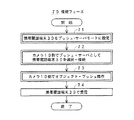
図5の例のデバイスアドレス取得処理ルーチン60では、カメラ10のCPU23は、デバイスアドレス取得モードにおいて、まずステップ61で、液晶モニタ15上に、「デバイスアドレス取得モードに入ります。カメラをバーコードに向けてください」などというように、カメラ10をバーコード35に向けるべきことを表示する。
【0045】
ユーザは、これに応答して、カメラ10を携帯電話端末30の液晶ディスプレイ32上のバーコード35が表示された部分に向ける。
【0046】
CPU23は、次にステップ62で、自らシャッターを開いてバーコード35を撮影し、次にステップ63で、CCD12から画像情報を読み出し、次にステップ64で、デバイスアドレスの認識処理を実行し、さらにステップ65で、デバイスアドレスを認識できたか否かを判断する。
【0047】
そして、デバイスアドレスを認識できなかったときには、ステップ65からステップ62に戻って、ステップ62での撮影、ステップ63での画像情報の読み出し、およびステップ64でのデバイスアドレスの認識処理を繰り返す。
【0048】
ステップ65でデバイスアドレスを認識できたと判断したときには、CPU23は、ステップ67に進んで、液晶モニタ15上に、「目的の機器を認識しました」などというように、目的の機器のデバイスアドレスを認識できたことを表示し、さらにステップ68に進んで、その認識したデバイスアドレスをDRAM25に登録する。ユーザは、ステップ67でデバイスアドレスが認識されたことが表示されたら、カメラ10の向きを変えることができる。
【0049】
上述した方法によれば、携帯電話端末30の液晶ディスプレイ32上にバーコード35を表示させ、カメラ10をデバイスアドレス取得モードに切り替えて、カメラ10でバーコード35を撮影するだけで、カメラ10において携帯電話端末30のデバイスアドレスを取得することができ、カメラ10と携帯電話端末30との間にBluetoothによる無線通信ネットワークを形成することができる。
【0050】
このようにカメラ10において携帯電話端末30のデバイスアドレスを取得して、カメラ10と携帯電話端末30との間にBluetoothによる無線通信ネットワークが形成されたら、カメラ10は、図6に示すような接続フェーズによって、携帯電話端末30に接続して、携帯電話端末30に情報を送信することができる。
【0051】
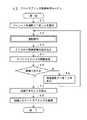
すなわち、接続フェーズ70では、ユーザは、まずステップ71で、携帯電話端末30をプッシュ・サーバモードに設定し、次にステップ72で、カメラ10側でプッシュ・サーバとして携帯電話端末30を選択して、携帯電話端末30に接続する。この選択は、カメラ10に登録されているカメラ10以外の機器のデバイスアドレスを液晶モニタ15上に呼び出し、その中から目的の携帯電話端末30のデバイスアドレスを指定することによって、行うことができる。
【0052】
バーコード35を、携帯電話端末30のデバイスアドレスおよびデバイスネームまたはデバイスカテゴリーを示したものとし、図3〜図5の例のようなデバイスアドレス取得処理ルーチンによって、カメラ10において携帯電話端末30のデバイスアドレスおよびデバイスネームまたはデバイスカテゴリーを取得するように構成すれば、ユーザは、デバイスネームまたはデバイスカテゴリーと併せて判断して、目的の携帯電話端末30を容易かつ確実に選択することができる。
【0053】
ユーザは、次にステップ73において、カメラ10側でオブジェクト・プッシュ操作を行って、カメラ10から携帯電話端末30に情報を送信する。これによって、ステップ74において、携帯電話端末30で情報が受信される。
【0054】
具体的には、例えば、カメラ10で人や風景などを撮影して得られた画像情報を、カメラ10から携帯電話端末30に送信して、携帯電話端末30上で作成したメールに添付し、携帯電話端末30から携帯電話回線を通じて送信することができる。
【0055】
なお、図3、図4または図5のステップ48,58または68でCPU23がデバイスアドレスを登録した後、引き続いて接続フェーズに移行できるように、デバイスアドレス取得処理ルーチンを構成することもできる。
【0056】
この場合、CPU23は、ステップ48,58または68でデバイスアドレスを登録した後、液晶モニタ15上に、「データを送信しますか」などというように、接続フェーズに移行するか否かを表示し、ユーザが接続フェーズに移行する旨の操作をしたときには、すでにプッシュ・サーバは選択されたものとして、液晶モニタ15上に、送信先の機器(プッシュ・サーバ)をプッシュ・サーバモードに設定し、送信する画像を液晶モニタ15上に呼び出して、オブジェクト・プッシュ操作をすべきことを表示し、ユーザが接続フェーズに移行しない旨の操作をしたときには、そのまま処理を終了するように、デバイスアドレス取得処理ルーチンを構成する。
【0057】
ユーザは、接続フェーズに移行するときには、上記の表示に従って、携帯電話端末30をプッシュ・サーバモードに設定し、カメラ10において、送信する画像を液晶モニタ15上に呼び出し、オブジェクト・プッシュ操作をする。
【0058】
携帯電話端末30のデバイスアドレスを、図7に示すような、サイバーコード(登録商標)などの2次元バーコード37で示して、液晶ディスプレイ32上に表示し、これをカメラ10で撮影するように、システムを構成してもよい。
【0062】
上述した実施形態は、プッシュ・クライアントがデジタルスチルカメラ10であり、プッシュ・サーバが携帯電話端末30である場合であるが、この発明は、例えば、プッシュ・クライアントがデジタルスチルカメラなどのカメラであり、プッシュ・サーバがPC(パーソナルコンピュータ)であって、カメラで得られた画像データを、Bluetoothによる無線通信によってPCに送信するシステムにも、適用することができる。
【0063】
また、この発明は、プッシュ・クライアントが、外部のカメラとの接続用のUSBインタフェースなどのインタフェース部を備え、外部のカメラからの画像情報を取り込むことができるPCなどの情報処理端末であって、そのPCなどの情報処理端末からプッシュ・サーバの機器に、Bluetoothによる無線通信によって画像データなどを送信するシステムにも、適用することができる。
【0064】
この場合には、PCなどの情報処理端末に接続した外部のカメラによって、プッシュ・サーバ機器のディスプレイ上に表示された、プッシュ・サーバ機器のデバイスアドレスを示すバーコードを撮影し、その得られた画像情報をPCなどの情報処理端末で処理することによって、PCなどの情報処理端末においてプッシュ・サーバ機器のデバイスアドレスを取得するように、システムを構成する。
【0065】
さらに、送信側デバイスである情報処理端末と受信側デバイスである目的の機器との間の無線通信方式としては、Bluetooth以外の方式を用いることもできる。この場合にも、この発明では、機器を一意に特定する情報をデバイスアドレスと定義する。
【0066】
【発明の効果】
上述したように、この発明によれば、送信対象となる目的の機器のデバイスアドレスを取得することによって、目的の機器との間に無線通信ネットワークを形成し、目的の機器に情報を送信する情報処理端末において、目的の機器のディスプレイ上に表示されて当該の情報処理端末の撮像部で撮像されることにより当該の情報処理端末の撮像部から画像情報として出力された、または目的の機器のディスプレイ上に表示されてカメラで撮像されることにより当該の情報処理端末のインタフェース部から画像情報として取り込まれた、目的の機器のデバイスアドレスを示すバーコードを認識することによって、目的の機器のデバイスアドレスを取得するので、目的の機器のデバイスアドレスを短時間で確実に取得することができる。
【図面の簡単な説明】
【図1】無線通信システムの一実施形態を示す図である。
【図2】情報処理端末の一実施形態の機能ブロック構成を示す図である。
【図3】デバイスアドレス取得処理ルーチンの第1の例を示す図である。
【図4】デバイスアドレス取得処理ルーチンの第2の例を示す図である。
【図5】デバイスアドレス取得処理ルーチンの第3の例を示す図である。
【図6】接続フェーズの一例を示す図である。
【図7】2次元バーコードの一例を示す図である。
【図8】Bluetoothの無線通信システムを示す図である。
【図9】従来のデバイスアドレス取得方法の一例を示す図である。
【符号の説明】
主要部については図中に全て記述したので、ここでは省略する。[0001]
BACKGROUND OF THE INVENTION
The present invention relates to an information processing terminal and an information processing method for forming a wireless communication network with a target device by acquiring information that uniquely specifies the target device to be transmitted.
[0002]
[Prior art]
As a method for performing communication between a plurality of devices in a limited area, a method of forming a wireless communication network by Bluetooth between a plurality of devices is considered.
[0003]
In Bluetooth, 'Bluetooth Device Address' is assigned to each device, and as shown in FIG. 8, the
[0004]
'Bluetooth Device Address' is information that uniquely identifies the Bluetooth device, and is expressed in 12 hexadecimal alphanumeric characters such as '00: 0C: 3E: 3A: 4B: 69' or '000C3E3A4B69'. This is an address of 48 bits (6 bytes) in total. Hereinafter, 'Bluetooth Device Address' is referred to as a device address.
[0005]
In addition to the device address, the Bluetooth device can be attached with 'Bluetooth Device Name' or 'Class of Device'. 'Bluetooth Device Name' indicates the name of the device such as 'VAIO (registered trademark) C1', and 'Class of Device' indicates the category name of the device such as 'PC' or 'PDA'. Indicates the name of the service provided by the device. Hereinafter, 'Bluetooth Device Name' is referred to as a device name, and 'Class of Device' is referred to as a device category.
[0006]
When the
[0007]
As a method for acquiring the device address of the
[0008]
In the device address acquisition processing routine of FIG. 9, the CPU of the
[0009]
Next, the CPU of the
[0010]
Next, in
[0011]
Next, in
[0012]
Thus, by acquiring the device address of the
[0013]
[Problems to be solved by the invention]
However, in the above-described conventional method, it takes about 10 to 30 seconds to search for a device once, and when there are some Bluetooth devices in addition to the
[0014]
When the
[0015]
Therefore, the present invention forms a wireless communication network with a target device by acquiring a device address of the target device to be transmitted (information that uniquely identifies the device is defined as a device address). In the information processing terminal, the device address of the target device can be reliably acquired in a short time.
[0016]
[Means for Solving the Problems]
The information processing terminal of the first invention is
An imaging unit that outputs the captured image as image information;
From the image information output from the imaging unit, a control unit that recognizes a barcode indicating device address information that uniquely identifies a device to be transmitted, and acquires a device address of the device;
A wireless transmission unit that wirelessly transmits information to the device specified by the device address acquired by the control unit,
The barcode is displayed on the display of the device to be transmitted, captured by the imaging unit, and output as the image information.
It is characterized by that.
[0017]
The information processing terminal of the second invention is
An interface unit for capturing image information;
From the image information captured from this interface unit, a controller that recognizes a barcode indicating device address information that uniquely identifies a device to be transmitted, and acquires a device address of the device;
A wireless transmission unit that wirelessly transmits information to the device specified by the device address acquired by the control unit,
The barcode is displayed on the display of the device to be transmitted, captured by the camera, and captured as the image information from the interface unit.
It is characterized by that.
[0018]
In the information processing terminal of the present invention configured as described above, on the display of the target device to be transmitted by the imaging unit included in the information processing terminal or the camera (imaging unit) connected to the information processing terminal. The device address of the target device can be acquired and the device address of the target device can be obtained for a short time simply by photographing the barcode displayed on the screen showing the device address information of the target device to be transmitted. It can be acquired with certainty.
[0019]
DETAILED DESCRIPTION OF THE INVENTION
FIG. 1 shows an embodiment of a wireless communication system according to the present invention. A wireless communication system is configured by a digital
[0020]
The digital
[0021]
The cellular phone terminal 30 includes an operation input unit 31 including various operation keys and character input keys, a liquid crystal display 32 as a display unit, and the like, and is equipped with a Bluetooth function as a push server.
[0022]
FIG. 2 shows a functional block configuration of the digital
[0023]
When the shutter switch 14 shown in FIG. 1 is pressed in the normal imaging mode or the device address acquisition mode described later, the CCD 12 is irradiated with light through the lens 11 and an image is taken. The image is output as image data by the
[0024]
The system bus 22 includes a
[0025]
The
[0026]
The image data output from the
[0027]
Image data output from the
[0028]
Further, as will be described later, image data obtained by the
[0029]
In the mobile phone terminal 30, the barcode 35 is displayed on the liquid crystal display 32 as an image indicating the device address of the mobile phone terminal 30 in the standby mode or by performing an operation of calling the device address with the operation input unit 31. The
[0030]
Specifically, the bar code 35 indicates that the error correction code is added to the device address of the mobile phone terminal 30, or the error correction code is added to the device address and the device name or the device category of the mobile phone terminal 30, respectively. Let's show what was added.
[0031]
When the user causes the
[0032]
Thereby, the
[0033]
In the device address acquisition processing routine 40 of the example of FIG. 3, in the device address acquisition mode, the
[0034]
In response to this, in
[0035]
Next, in
[0036]
Next, in step 45, the
[0037]
Accordingly, the user again presses the shutter switch 14 to photograph the barcode 35 in
[0038]
When it is determined in step 45 that the device address has been recognized, the
[0039]
In the device address acquisition processing routine 50 of the example of FIG. 4, in the device address acquisition mode, the
[0040]
In response to this, in step 52, the user keeps pressing the shutter switch 14 with the
[0041]
Next, in
[0042]
If the device address cannot be recognized, the process returns from step 55 to step 53, and the reading of the image information in
[0043]
When it is determined in step 55 that the device address has been recognized, the
[0044]
In the device address acquisition processing routine 60 of the example of FIG. 5, in the device address acquisition mode, the
[0045]
In response to this, the user points the
[0046]
Next, in step 62, the
[0047]
If the device address cannot be recognized, the process returns from step 65 to step 62, and the photographing at step 62, the reading of image information at
[0048]
When it is determined in step 65 that the device address has been recognized, the
[0049]
According to the above-described method, the barcode 35 is displayed on the liquid crystal display 32 of the mobile phone terminal 30, the
[0050]
When the device address of the mobile phone terminal 30 is acquired in the
[0051]
That is, in the connection phase 70, the user first sets the mobile phone terminal 30 to the push server mode in
[0052]
The bar code 35 indicates the device address and device name or device category of the mobile phone terminal 30, and the device of the mobile phone terminal 30 is used in the
[0053]
Next, in
[0054]
Specifically, for example, image information obtained by photographing a person or a landscape with the
[0055]
It should be noted that the device address acquisition processing routine can be configured so that the
[0056]
In this case, after registering the device address in
[0057]
When the user shifts to the connection phase, the mobile phone terminal 30 is set to the push server mode according to the above display, and the
[0058]
The device address of the mobile phone terminal 30 is indicated by a two-
[0062]
The embodiment described above is a case where the push client is the digital
[0063]
Further, the present invention is an information processing terminal such as a PC in which the push client includes an interface unit such as a USB interface for connection with an external camera and can capture image information from the external camera . The present invention can also be applied to a system in which image data or the like is transmitted from an information processing terminal such as a PC to a push server device by wireless communication using Bluetooth.
[0064]
In this case, a bar code indicating the device address of the push server device displayed on the display of the push server device is photographed by an external camera connected to an information processing terminal such as a PC, and the obtained result is obtained. By processing the image information with an information processing terminal such as a PC, the system is configured such that the device address of the push server device is acquired at the information processing terminal such as the PC.
[0065]
Furthermore, a method other than Bluetooth can be used as a wireless communication method between the information processing terminal that is the transmitting device and the target device that is the receiving device. Also in this case, in the present invention, information for uniquely specifying a device is defined as a device address.
[0066]
【The invention's effect】
As described above, according to the present invention, by acquiring the device address of a target device to be transmitted, a wireless communication network is formed with the target device, and information is transmitted to the target device. Displayed on the display of the target device at the processing terminal and imaged by the imaging unit of the information processing terminal and output as image information from the imaging unit of the information processing terminal, or the display of the target device The device address of the target device is recognized by recognizing the barcode indicating the device address of the target device, which is displayed as image information from the interface unit of the information processing terminal by being displayed on and captured by the camera. Therefore, the device address of the target device can be reliably acquired in a short time.
[Brief description of the drawings]
FIG. 1 is a diagram illustrating an embodiment of a wireless communication system.
FIG. 2 is a diagram showing a functional block configuration of an embodiment of an information processing terminal.
FIG. 3 is a diagram illustrating a first example of a device address acquisition processing routine.
FIG. 4 is a diagram illustrating a second example of a device address acquisition processing routine.
FIG. 5 is a diagram showing a third example of a device address acquisition processing routine.
FIG. 6 is a diagram illustrating an example of a connection phase.
FIG. 7 is a diagram illustrating an example of a two-dimensional barcode.
FIG. 8 is a diagram illustrating a Bluetooth wireless communication system.
FIG. 9 is a diagram illustrating an example of a conventional device address acquisition method.
[Explanation of symbols]
Since all the main parts are described in the figure, they are omitted here.
Claims (5)
この撮像部から出力された画像情報から、送信対象となる機器を一意に特定するデバイスアドレス情報を示すバーコードを認識し、上記機器のデバイスアドレスを取得する制御部と、
この制御部で取得されたデバイスアドレスによって特定された機器に情報を無線で送信する無線送信部とを備え、
上記バーコードは、送信対象となる機器のディスプレイ上に表示され、上記撮像部によって撮像されて上記画像情報として出力されたものである、
ことを特徴とする情報処理端末。An imaging unit that outputs the captured image as image information;
From the image information output from the imaging unit, a control unit that recognizes a barcode indicating device address information that uniquely identifies a device to be transmitted, and acquires a device address of the device;
A wireless transmission unit that wirelessly transmits information to the device specified by the device address acquired by the control unit,
The barcode is displayed on the display of the device to be transmitted, captured by the imaging unit, and output as the image information.
An information processing terminal characterized by that.
このインタフェース部から取り込まれた画像情報から、送信対象となる機器を一意に特定するデバイスアドレス情報を示すバーコードを認識し、上記機器のデバイスアドレスを取得する制御部と、
この制御部で取得されたデバイスアドレスによって特定された機器に情報を無線で送信する無線送信部とを備え、
上記バーコードは、送信対象となる機器のディスプレイ上に表示され、カメラによって撮像されて、上記インタフェース部から上記画像情報として取り込まれたものである、
ことを特徴とする情報処理端末。An interface unit for capturing image information;
From the image information captured from this interface unit, a controller that recognizes a barcode indicating device address information that uniquely identifies a device to be transmitted, and acquires a device address of the device;
A wireless transmission unit that wirelessly transmits information to the device specified by the device address acquired by the control unit,
The barcode is displayed on the display of the device to be transmitted, captured by the camera, and captured as the image information from the interface unit.
An information processing terminal characterized by that.
上記バーコードは、1次元または2次元のバーコードであることを特徴とする情報処理端末。In the information processing terminal according to claim 1 or 2,
The information processing terminal according to claim 1, wherein the barcode is a one-dimensional or two-dimensional barcode.
上記コンピュータが備える第1制御手段が、上記情報処理端末の撮像部から出力された画像情報から、送信対象となる機器を一意に特定するデバイスアドレス情報を示すバーコードを認識し、上記機器のデバイスアドレスを取得する第1ステップと、
上記コンピュータが備える第2制御手段が、上記情報処理端末の無線送信部に対して、上記第1制御手段によって上記第1ステップで取得されたデバイスアドレスによって特定された機器に情報を無線で送信させる第2ステップとを備え、
上記バーコードは、送信対象となる機器のディスプレイ上に表示され、上記撮像部によって撮像されて上記画像情報として出力されたものである、
ことを特徴とする情報処理方法。An information processing method in an information processing terminal including a computer,
The first control means included in the computer recognizes a barcode indicating device address information that uniquely identifies the device to be transmitted from the image information output from the imaging unit of the information processing terminal, and the device of the device A first step of obtaining an address;
The second control means included in the computer causes the wireless transmission unit of the information processing terminal to wirelessly transmit information to the device specified by the device address acquired in the first step by the first control means. A second step,
The barcode is displayed on the display of the device to be transmitted, captured by the imaging unit, and output as the image information.
An information processing method characterized by the above.
上記コンピュータが備える第1制御手段が、上記情報処理端末のインタフェース部から取り込まれた画像情報から、送信対象となる機器を一意に特定するデバイスアドレス情報を示すバーコードを認識し、上記機器のデバイスアドレスを取得する第1ステップと、
上記コンピュータが備える第2制御手段が、上記情報処理端末の無線送信部に対して、上記第1制御手段によって上記第1ステップで取得されたデバイスアドレスによって特定された機器に情報を無線で送信させる第2ステップとを備え、
上記バーコードは、送信対象となる機器のディスプレイ上に表示され、カメラによって撮像されて、上記インタフェース部から上記画像情報として上記情報処理端末に取り込まれたものである、
ことを特徴とする情報処理方法。An information processing method in an information processing terminal including a computer,
The first control means included in the computer recognizes a barcode indicating device address information that uniquely identifies a device to be transmitted from the image information captured from the interface unit of the information processing terminal, and the device of the device A first step of obtaining an address;
The second control means included in the computer causes the wireless transmission unit of the information processing terminal to wirelessly transmit information to the device specified by the device address acquired in the first step by the first control means. A second step,
The barcode is displayed on a display of a device to be transmitted, captured by a camera, and taken into the information processing terminal as the image information from the interface unit.
An information processing method characterized by the above.
Priority Applications (1)
| Application Number | Priority Date | Filing Date | Title |
|---|---|---|---|
| JP2001368271A JP4174208B2 (en) | 2001-12-03 | 2001-12-03 | Information processing terminal and information processing method |
Applications Claiming Priority (1)
| Application Number | Priority Date | Filing Date | Title |
|---|---|---|---|
| JP2001368271A JP4174208B2 (en) | 2001-12-03 | 2001-12-03 | Information processing terminal and information processing method |
Related Child Applications (1)
| Application Number | Title | Priority Date | Filing Date |
|---|---|---|---|
| JP2007032022A Division JP4264759B2 (en) | 2007-02-13 | 2007-02-13 | Information processing terminal and information processing method |
Publications (3)
| Publication Number | Publication Date |
|---|---|
| JP2003169187A JP2003169187A (en) | 2003-06-13 |
| JP2003169187A5 JP2003169187A5 (en) | 2005-07-14 |
| JP4174208B2 true JP4174208B2 (en) | 2008-10-29 |
Family
ID=19177886
Family Applications (1)
| Application Number | Title | Priority Date | Filing Date |
|---|---|---|---|
| JP2001368271A Expired - Fee Related JP4174208B2 (en) | 2001-12-03 | 2001-12-03 | Information processing terminal and information processing method |
Country Status (1)
| Country | Link |
|---|---|
| JP (1) | JP4174208B2 (en) |
Cited By (1)
| Publication number | Priority date | Publication date | Assignee | Title |
|---|---|---|---|---|
| US9215003B2 (en) | 2012-03-02 | 2015-12-15 | Olympus Corporation | Communication apparatus, communication method, and computer readable recording medium |
Families Citing this family (16)
| Publication number | Priority date | Publication date | Assignee | Title |
|---|---|---|---|---|
| GB2412265B (en) * | 2003-01-14 | 2007-10-24 | Sanyo Electric Co | Captured image outputting system, display control apparatus, liquid crystal projector and digital camera that transmit images via wireless network |
| JP2004221908A (en) | 2003-01-14 | 2004-08-05 | Sanyo Electric Co Ltd | Method for controlling display, photographed image output sysetm capable of using the method, display control device, liquid crystal projector, and digital camera |
| US7124953B2 (en) | 2003-12-29 | 2006-10-24 | Nokia Corporation | Visual encoding of a content address to facilitate data transfer in digital devices |
| GB2409923A (en) * | 2004-01-08 | 2005-07-13 | Coupon Ltd I | LCD bar code orientation |
| JP3821139B2 (en) | 2004-05-14 | 2006-09-13 | コニカミノルタビジネステクノロジーズ株式会社 | Data output system and data output device |
| KR100678169B1 (en) * | 2004-10-28 | 2007-02-02 | 삼성전자주식회사 | System and method for transmitting data between two terminal equipments distant from each other |
| JP2006261938A (en) | 2005-03-16 | 2006-09-28 | Sony Corp | Communications system, communications apparatus and method, recording medium, and program |
| JP2007025351A (en) * | 2005-07-19 | 2007-02-01 | Yamaha Corp | Playing system |
| JP2007034443A (en) | 2005-07-22 | 2007-02-08 | Konica Minolta Business Technologies Inc | Image formation system, image formation device, and image formation processing method |
| JP4920492B2 (en) * | 2007-05-21 | 2012-04-18 | オリンパスイメージング株式会社 | Imaging device |
| JP2013167969A (en) | 2012-02-14 | 2013-08-29 | Canon Inc | Image output device, portable terminal device, image output method, information processing method and program |
| JP5993164B2 (en) | 2012-03-08 | 2016-09-14 | オリンパス株式会社 | COMMUNICATION DEVICE, COMMUNICATION METHOD, AND PROGRAM |
| JP5901413B2 (en) * | 2012-05-02 | 2016-04-13 | オリンパス株式会社 | Imaging device and communication device |
| JP6167647B2 (en) * | 2013-05-01 | 2017-07-26 | 株式会社ニコン | Imaging apparatus, system, method, and program |
| JP7456098B2 (en) * | 2019-07-17 | 2024-03-27 | 富士フイルムビジネスイノベーション株式会社 | Information processing device and program |
| JP7285815B2 (en) * | 2020-11-16 | 2023-06-02 | ソフトバンク株式会社 | Glasses type device and program |
-
2001
- 2001-12-03 JP JP2001368271A patent/JP4174208B2/en not_active Expired - Fee Related
Cited By (1)
| Publication number | Priority date | Publication date | Assignee | Title |
|---|---|---|---|---|
| US9215003B2 (en) | 2012-03-02 | 2015-12-15 | Olympus Corporation | Communication apparatus, communication method, and computer readable recording medium |
Also Published As
| Publication number | Publication date |
|---|---|
| JP2003169187A (en) | 2003-06-13 |
Similar Documents
| Publication | Publication Date | Title |
|---|---|---|
| JP4174208B2 (en) | Information processing terminal and information processing method | |
| US7455229B2 (en) | Direct print system | |
| US7062230B1 (en) | Communication device, image-pickup device, storage medium and communication method | |
| EP1585306A1 (en) | Digital still camera and method of controlling same | |
| JP2003091409A (en) | Cradle format printer device for portable terminal and its printing processing method and storage medium | |
| JP4679684B2 (en) | Wireless communication apparatus and wireless communication control method | |
| KR101606134B1 (en) | Apparatus and method for connecting device using the image recognition in portable terminal | |
| JP5086867B2 (en) | Digital camera | |
| US20060146140A1 (en) | Apparatus for wireless operation and control of a camera | |
| JP4264759B2 (en) | Information processing terminal and information processing method | |
| JP4312642B2 (en) | Wireless LAN transmitter and control method thereof | |
| JP2009027647A (en) | Captured image recording system, photographic device, captured image recording method | |
| JP4818001B2 (en) | Imaging apparatus, control method thereof, and program | |
| JP2000287115A (en) | Digital camera and digital camera system | |
| JP2003319311A (en) | Image processing apparatus and system | |
| JPH1065889A (en) | Digital still camera | |
| JP2002232761A (en) | Picture recording method, picture transmission method and picture recording apparatus | |
| JP2008252317A (en) | Digital camera | |
| JP3706824B2 (en) | Image data transmission method, communication apparatus, image data transmission program, and storage medium | |
| JP2003143457A (en) | Information apparatus system | |
| CA2531617A1 (en) | Apparatus for wireless operation and control of a camera | |
| JP4344956B2 (en) | Image recording method and image recording apparatus | |
| JP2004173255A (en) | Continuous photographing method and digital camera | |
| JP2002271723A (en) | Image recording method and image record system | |
| KR20050014972A (en) | Digital photographing system and storing method using bluetooth |
Legal Events
| Date | Code | Title | Description |
|---|---|---|---|
| A521 | Request for written amendment filed |
Free format text: JAPANESE INTERMEDIATE CODE: A523 Effective date: 20041119 |
|
| A621 | Written request for application examination |
Free format text: JAPANESE INTERMEDIATE CODE: A621 Effective date: 20041119 |
|
| A977 | Report on retrieval |
Free format text: JAPANESE INTERMEDIATE CODE: A971007 Effective date: 20060214 |
|
| A131 | Notification of reasons for refusal |
Free format text: JAPANESE INTERMEDIATE CODE: A131 Effective date: 20060222 |
|
| A521 | Request for written amendment filed |
Free format text: JAPANESE INTERMEDIATE CODE: A523 Effective date: 20060424 |
|
| A02 | Decision of refusal |
Free format text: JAPANESE INTERMEDIATE CODE: A02 Effective date: 20061213 |
|
| A521 | Request for written amendment filed |
Free format text: JAPANESE INTERMEDIATE CODE: A523 Effective date: 20070213 |
|
| A911 | Transfer to examiner for re-examination before appeal (zenchi) |
Free format text: JAPANESE INTERMEDIATE CODE: A911 Effective date: 20070226 |
|
| A912 | Re-examination (zenchi) completed and case transferred to appeal board |
Free format text: JAPANESE INTERMEDIATE CODE: A912 Effective date: 20070316 |
|
| A521 | Request for written amendment filed |
Free format text: JAPANESE INTERMEDIATE CODE: A523 Effective date: 20080715 |
|
| A01 | Written decision to grant a patent or to grant a registration (utility model) |
Free format text: JAPANESE INTERMEDIATE CODE: A01 |
|
| A61 | First payment of annual fees (during grant procedure) |
Free format text: JAPANESE INTERMEDIATE CODE: A61 Effective date: 20080818 |
|
| FPAY | Renewal fee payment (event date is renewal date of database) |
Free format text: PAYMENT UNTIL: 20110822 Year of fee payment: 3 |
|
| LAPS | Cancellation because of no payment of annual fees |