JP4106311B2 - Information embedding device, encoding device, falsification detection device, method thereof, and recording medium recording program for executing the method - Google Patents
Information embedding device, encoding device, falsification detection device, method thereof, and recording medium recording program for executing the method Download PDFInfo
- Publication number
- JP4106311B2 JP4106311B2 JP2003191847A JP2003191847A JP4106311B2 JP 4106311 B2 JP4106311 B2 JP 4106311B2 JP 2003191847 A JP2003191847 A JP 2003191847A JP 2003191847 A JP2003191847 A JP 2003191847A JP 4106311 B2 JP4106311 B2 JP 4106311B2
- Authority
- JP
- Japan
- Prior art keywords
- frequency
- feature information
- region
- image signal
- unit
- Prior art date
- Legal status (The legal status is an assumption and is not a legal conclusion. Google has not performed a legal analysis and makes no representation as to the accuracy of the status listed.)
- Expired - Fee Related
Links
Images


Landscapes
- Facsimile Image Signal Circuits (AREA)
- Compression Or Coding Systems Of Tv Signals (AREA)
- Compression, Expansion, Code Conversion, And Decoders (AREA)
- Compression Of Band Width Or Redundancy In Fax (AREA)
- Image Processing (AREA)
- Television Systems (AREA)
- Editing Of Facsimile Originals (AREA)
Description
【0001】
【発明の属する技術分野】
本発明は、情報埋め込み装置、改ざん検出装置及びそれらの関連技術に関するものである。特に、本発明は、デジタル画像信号を画像圧縮する場合に、画像圧縮データが改ざんされているか否か判定するための特徴情報を電子透かしとして埋め込み、検出する技術に関する。
【0002】
【従来の技術】
近年、防犯などのセキュリティ上の観点から、監視システムの需要が拡大している。特に、監視用記録装置の分野では、ユーザーは、長時間録画ができること、画質が高いことを強く求めている。
【0003】
このため、デジタル化した画像データを画像圧縮し、デジタルのまま記録するデジタルディスクレコーダーが、急速に普及している。
【0004】
デジタルデータを、市販の画像処理ソフトウェアを用いて、改ざん(例えば、編集・加工など)することは、容易である。
【0005】
なお、以上の説明は、監視用記録装置やデジタルディスクレコーダーを例にしているが、本発明は、これらの用途に限定されず、画像処理を実施する技術に広く適用できる。
【0006】
デジタル画像に改ざんが加えられているか否か判定できる改ざん検出技術を確立することが求められている。従来、その対策の一つとして知られているものに電子認証技術がある。
【0007】
図13は、従来の電子認証の手順の概要を示す。図13において、送信装置は、オリジナルのデジタル画像にハッシュ関数を適用しハッシュ値を得る。また、送信装置は、このハッシュ値に基づいてデジタル画像を圧縮し、ダイジェストを生成する。
【0008】
次に、送信装置は、このダイジェストを、送り手の秘密鍵で暗号化する。そして、送信装置は、オリジナルのデジタル画像と暗号化されたダイジェストとの両方のデータを、ネットワークを介して、受信装置に送信する。
【0009】
受信装置は、ネットワークを介して、この両方のデータを受信する。受信装置は、受信したデジタル画像を、ハッシュ値により圧縮し、第1のダイジェストを作成する。また、受信装置は、受信したダイジェストを、送り手の公開鍵により復号し、第2のダイジェストを作成する。
【0010】
そして、受信装置は、第1のダイジェストと第2のダイジェストとを比較し、これらが、同一であれば改ざんがないと判定し、同一でなければ改ざんがあると判定する。
【0011】
ところが、上述の電子認証において、送信装置は、オリジナルのデジタル画像と暗号化されたダイジェストとの、2種類のデータを、受信装置へ送信しなければならない。
【0012】
デジタル画像が大量に存在するときは、デジタル画像とダイジェストとの対応関係を管理するデータ管理装置が、事実上必要不可欠である。
【0013】
このようなデータ管理装置に替えて、従来より、電子透かしを用いた手法が知られている。電子透かしとは、デジタル画像データの内部に、人間の目では知覚できないように、デジタル情報を埋め込む技術である。
【0014】
このような電子透かし技術を用いた改ざん検出方法が提案されている。例えば、特許文献1(特開平10−164549号公報)は、画像認証システムを開示する。
【0015】
以下、図14を参照しながら、このシステムについて簡単に説明する。デジタルカメラなどにおいて撮影された対象の画像データD(図14(a)参照)は、ハッシュ値を生成するための画像領域D1と、生成されたハッシュ値Hを埋め込む画像領域D2とに分割される(図14(b)参照)。
【0016】
ダイジェスト計算部(図示せず)は、画像領域D1のデータからハッシュ値Hを計算し、デジタルカメラごとに異なる秘密鍵で暗号化するなどして、画像領域D2にハッシュ値Hを埋め込む。
【0017】
一方、図14(c)に示すように、検証装置は、画像領域D1のデータから第1のハッシュ値H1を生成する。
【0018】
また、検証装置は、画像領域D2から埋め込まれているハッシュ値H2を抽出し、抽出された第2のハッシュ値H2を公開鍵を用いて復号する。
【0019】
そして、検証装置は、第1のハッシュ値H1と第2のハッシュ値H2とを比較することにより、画像データDが改ざんされているか判定する。
【0020】
また、特許文献2(特開平11−341268号公報)の技術は、圧縮デジタル画像を部分的にデコードし、データブロックの係数に基づきハッシュ値を埋め込むか否かを判定しながら、全てのブロックからハッシュ値を計算する。
【0021】
次に、この技術は、再度、圧縮デジタル画像を部分的にデコードし、埋め込むべきブロックの係数とハッシュ値との1ビットを置き換えて透かしビットを埋め込む。
【特許文献1】
特開平10−164549号公報
【特許文献2】
特開平11−341268号公報
【0022】
【発明が解決しようとする課題】
しかしながら、特許文献1の技術は、画素空間において処理を行っている。このため、画素空間において、画像データが変化する処理(例えば、画像符号化等)を行うと、その処理の前後で、第1のハッシュ値H1と第2のハッシュ値H2とが、全く異なる値となってしまうから、ハッシュ値の比較による検証が不可能である。したがって、この技術は、画像圧縮されたデジタル画像の改ざん検出に適用できない。
【0023】
また、特許文献2の技術は、ハッシュ値の埋め込みのために、画像圧縮データを二度もデコードすることを前提とする。しかも、この技術では、通常用いられる量子化テーブルの変数値を、少なくとも一係数分変更しなければならない。したがって、改ざん検出のための処理が非常に複雑である。
【0024】
さらに、これらの従来技術では、故意の改ざん(例えば、画像の一部をすり替えたりする変更)と、悪意はないが一般的に行われる非可逆的な画像処理による変更とを、区別することができない。
【0025】
本発明は、簡易な手順で画像圧縮データの改ざん検出を可能にする技術を提供することを第1の目的とする。
【0026】
本発明は、画像符号化と親和性がある技術を提供することを第2の目的とする。
【0027】
本発明は、画像圧縮データを完全に復号しなくとも、改ざんを検出できる技術を提供することを第3の目的とする。
【0028】
さらに、本発明は、故意の改ざんと非可逆的な画像処理とを区別できる技術を提供することを第4の目的とする。
【0045】
第5の発明に係る改ざん検出装置は、デジタル画像信号を周波数変換して得られる周波数係数のうち、第1の周波数領域に属する係数に基づいて第1の特徴情報を算出する特徴情報算出部と、デジタル画像信号を周波数変換して得られる周波数係数のうち、第1の周波数領域とは異なる第2の周波数領域に属する周波数係数に基づいて第2の特徴情報とデジタル画像信号を周波数変換して得られる周波数係数のうち、第1の周波数領域及び第2の周波数領域とは異なる第3の周波数領域に属する周波数係数に基づいて第3の特徴情報とを抽出する特徴情報抽出部と、第1の特徴情報と第2の特徴情報と第3の特徴情報のうち、いずれか2つ以上の特徴情報を比較し、改ざんの有無を判定する改ざん判定部とを備える。
【0046】
この構成により、画像圧縮データの復号プロセスの途中において、特徴情報の抽出と改ざん判定とを行える。
【0047】
第7の発明に係る改ざん検出装置では、第5から第6のいずれかの発明に加えて、第2の周波数領域は第1の周波数領域よりも高い周波数を持ち、第3の周波数領域は第2の周波数領域よりも高い周波数を持ち、改ざん判定部は、第1の特徴情報と第2の特徴情報とが一致し、かつ、第1の特徴情報と第3の特徴情報とが一致しないとき、改ざんはなく、かつ、画像処理が行われたものと判定する。
【0048】
この構成により、第1の特徴情報と第2の特徴情報とが一致し、かつ、第1の特徴情報と第3の特徴情報とが一致しない場合があり得るため、故意の改ざんと画像処理による画像の変化とを区別できる。
【0049】
【発明の実施の形態】
以下、図面を参照しながら、本発明の実施の形態を説明する。
【0050】
(第1の実施の形態)
【0051】
図1は、本発明の第1の実施の形態に係る情報埋め込み装置のブロック図である。図1に示すように、本形態の情報埋め込み装置は、周波数変換部101と量子化部102と特徴情報算出部103と情報埋め込み部104と画像符号化部105を備える。この情報埋め込み装置は、画像符号化部105を備えるので、符号化装置でもある。
【0052】
周波数変換部101は、デジタル画像信号を周波数変換して周波数係数(係数データ)を出力する。
【0053】
周波数変換部101における周波数変換は、離散ウェーブレット変換、サブバンド分割、離散コサイン変換、またはフーリエ変換のいずれかとすることができる。
【0054】
量子化部102は、周波数変換部101が出力する係数データを量子化して量子データ(量子化された周波数係数)を出力する。
【0055】
量子化部102における量子化処理は、周波数係数を一定のビット数のデータに置き換える操作であれば、任意に選択できる。例えば、複数の周波数係数をまとめてベクトル量子化してもよい。
【0056】
特徴情報算出部103は、量子化部102が出力する量子データのうち、第1の周波数領域に属する量子データに基づいて特徴情報を算出する。
【0057】
特徴情報算出部103が算出する特徴情報は、基になる値を固有に表現できる情報であり、本形態では、基になる値のハッシュ値とする。
【0058】
本形態では、特徴情報をハッシュ値としたが、これに限定したものではない。例えば、周波数係数値の1つの変更に対して、全く異なる値に変わる特徴情報であれば何でもよい。
【0059】
情報埋め込み部104は、量子化部102が出力する量子データのうち、第1の周波数領域とは異なる第2の周波数領域に属する量子データに、特徴情報を埋め込み、埋め込みデータを出力する。
【0060】
第1の周波数領域と第2の周波数領域は、最高周波数領域よりも周波数が低い、最低周波数領域または中低域周波数領域である。第1の周波数領域と第2の周波数領域については、後に詳述する。
【0061】
画像符号化部105は、情報埋め込み部104が出力する埋め込みデータを符号化して画像圧縮データを生成する。
【0062】
次に、図2を参照しながら、周波数変換として、離散ウェーブレット変換を使用する場合について説明する。図2(a)は、原画像を示し、図2(b)は、離散ウェーブレット変換後の周波数係数を示す。
【0063】
図2(b)において、右側あるいは下側が周波数が高く、左側あるいは上側は周波数が低い。周波数成分HH1は、最高周波数領域に属し、周波数成分LL2は、最低周波数領域に属する。また、周波数成分HL2、LH2、HH2は、中低周波数領域に属する。
【0064】
なお、図2(b)には、2次のウェーブレット変換による周波数係数を示しているが、3次など他の次数を用いても良い。
【0065】
上述したように、特徴情報算出部103は、量子化部102で量子化された複数の周波数成分から第1の周波数領域を選択する。ここで、本形態では、最低周波数領域(周波数成分LL2)を第1の周波数領域として選択する。
【0066】
したがって、特徴情報算出部103は、周波数成分LL2の係数データから所定の演算により特徴情報を算出する。
【0067】
また本形態では、中低周波数領域(周波数成分HL2、LH2、HH2)を第2の周波数領域として選択し、周波数成分HL2、LH2、HH2に、所定の規則で、特徴情報(ハッシュ値H)を埋め込む。
【0068】
ここで、低周波領域の周波数係数は、非可逆的な画像処理では変化しにくい。画像処理により変化しにくい領域に、特徴情報を埋め込んでいるので、特徴情報を欠落から保護できる。
【0069】
次に、図3を参照しながら、周波数変換として、離散コサイン変換(DCT)を使用する場合について説明する。
【0070】
画像の符号化方式として、JPEGやMPEGが使用される場合には、離散コサイン変換(DCT)を用いたほうがより好ましい。なぜなら、既にDCT/IDCT(Inverse DCT)のための変換要素が実装済であることが多いから、既存の回路又は要素を転用でき、規模拡大を防止できるからである。
【0071】
さて、図3(a)は、原画像を示し、図3(b)は、図3(a)に矩形で示すブロック(8×8画素)が変換された後のDCT係数を示す。
【0072】
図3(b)において、横軸iあるいは縦軸jが「7」に近いほど周波数が高く、横軸iあるいは縦軸jが「0」に近いほど周波数が低い。(i,j)=(0,0)なる係数は、直流(DC)係数であり、それ以外は、全て交流(AC)係数である。係数(7,7)は、最高周波数領域に属し、係数(0,0)は、最低周波数領域に属する。
【0073】
離散コサイン変換を用いた場合、全てのブロック(8×8画素)において、第1の周波数領域としてDC係数を除く63個のAC係数を、第2の周波数係数としてDC係数を、選択するとよい。あるいは、第1の周波数領域としてDC係数を使用し、第2の周波数領域としてAC係数でDC係数の近傍にあるものを使用することもできる。
【0074】
なお、埋め込み手法自体は、周知の技術を用いることができるが、図4に示すようなビットプレーンを使用することもできる。
【0075】
図4は、本発明の第1の実施の形態におけるビットプレーンと特徴情報との関係図である。図2(b)に示した周波数係数LL2、...、HH1は、図2(b)の紙面と平行なxy平面に対して、高さ成分zを有する。
【0076】
図4に示すように、この高さ成分zが、n(例えば、n=8等)ビットで表現されるとき、LSB(又はMSB)を1枚目のビットプレーンP1に割り当て、同様に、MSB(又はLSB)をn枚目のビットプレーンPnに割り当てる。
【0077】
このようにして、特徴情報を、該当するビットプレーンに埋め込むことができる。そうしても、本形態に包含される。そして、ビットプレーンの使用形態は種々考えられるが、例えば、特徴情報をMSBのビットプレーン(第1の周波数係数として使用)から求め、MSBの次のビットプレーン(第2の周波数係数として使用)に特徴情報を埋め込むようにするとよい。
【0078】
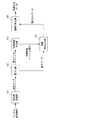
以下、図5を参照して、本発明の第1の実施の形態に係る情報埋め込み装置の動作について説明する。図5は、本発明の第1の実施の形態に係る情報埋め込み装置のフローチャートである。
【0079】
まず、ステップ1にて、周波数変換部101は、入力されるデジタル画像信号を周波数変換する。
【0080】
次に、ステップ2にて、量子化部102は、周波数変換部101で出力された周波数係数を所定の規則に従う量子化ステップサイズで量子化処理を行う。
【0081】
次に、ステップ3にて、特徴情報算出部103は、第1の周波数領域の係数に基づいて特徴情報(ハッシュ値H)を算出する。
【0082】
次に、ステップ4にて、情報埋め込み部104は、特徴情報算出部103が算出した特徴情報(ハッシュ値H)を、第1の周波数領域と異なる領域である第2の周波数領域中の係数に、所定の規則で操作して埋め込む。
【0083】
次に、ステップ5にて、画像符号化部105は、複数の周波数成分を表す周波数係数を符号化し画像圧縮データを生成する。
【0084】
以上のように、本発明の第1の実施の形態に係る情報埋め込み装置は、デジタル画像信号を周波数変換した周波数係数から直接ハッシュ値を算出し、所定の規則に基づき周波数係数を操作することにより、ハッシュ値を周波数係数に埋め込む。
【0085】
これにより、画像符号化の過程で埋め込みが可能であることから、より簡易な手順で画像圧縮データの改ざん検出を可能であり、画像符号化との親和性がある。
【0086】
なお、複数の周波数成分から周波数領域を選択する手法は、本形態で説明した組み合わせ以外にも、第1の周波数領域と第2の周波数領域が相異なる組み合わせを選択すれば、これに限定されない。例えば、第1の周波数領域としてLL2を、第2の周波数係数としてHH2を選択するような組み合わせでもよい。つまり、複数の周波数成分から全てを選択する必要はない。
【0087】
(第2の実施の形態)
【0088】
図6は、本発明の第2の実施の形態に係る改ざん検出装置のブロック図である。本形態の改ざん検出装置300は、実施の形態1の情報埋め込み装置に対応するものであり、第1の特徴情報および第2の特徴情報は、基になる値のハッシュ値である。
【0089】
図6に示すように、本形態の改ざん検出装置300は、画像復号部301と特徴情報算出部302と特徴情報抽出部303と改ざん判定部304を備える。
【0090】
画像復号部301は、画像圧縮データを復号して周波数係数(量子データ)を出力する。即ち、画像復号部301は、周波数係数を出力できさえすれば十分であって、必ずしも、逆量子化部や可変長復号部等を備えていなくとも良い。
【0091】
この周波数係数は、画像圧縮データを復号する過程で出力される量子化された周波数成分のデータである。
【0092】
また、第1の周波数領域と第2の周波数領域は、最高周波数領域よりも周波数が低い領域、中低周波数領域が望ましい。
【0093】
特徴情報算出部302は、画像復号部が出力する周波数係数(量子データ)に基づいて第1の特徴情報を算出し、改ざん判定部304へ出力する。
【0094】
特徴情報抽出部303は、画像復号部が出力する周波数係数(量子データ)に基づいて第2の特徴情報を算出し、改ざん判定部304へ出力する。
【0095】
改ざん判定部304は、第1の特徴情報と第2の特徴情報とを比較して改ざんの有無を判定する。より具体的には、改ざん判定部304は、第1の特徴情報と前記第2の特徴情報とを比較し、一致する場合には、改ざんされていないと判定する。
【0096】
なお、改ざん判定部304の判定結果は、本形態の改ざん検出装置300の外部に位置する、主メモリ400へ格納された後、表示制御部401に制御されるディスプレイ402に表示される。
【0097】
以下、図7を参照して、本発明の第2の実施の形態に係る改ざん検出装置の動作について説明する。図7は、本発明の第2の実施の形態に係る改ざん検出装置のフローチャートである。
【0098】
まず、ステップ11にて、画像復号部301は、画像圧縮データを所定の復号化処理を行い、量子データを、特徴情報算出部302と特徴情報抽出部303とに出力する。
【0099】
次に、ステップ12にて、特徴情報算出部302は、量子データのうち、第1の周波数領域に属する成分に基づいて演算し、第1の特徴情報を算出する。
【0100】
なお、特徴情報としては、第1の周波数領域全体の係数データから計算したハッシュ値H1とする。
【0101】
次に、ステップ13にて、特徴情報抽出部303は、量子データのうち、第2の周波数領域に属する成分から、第2の特徴情報を抽出する。
【0102】
次に、ステップ14にて、改ざん判定部304は、特徴情報算出部302で算出した第1の特徴情報と、特徴情報抽出部303で抽出した第2の特徴情報とを、比較し、これらの特徴情報が一致する場合には、対象の画像圧縮データが改変されていないと判定する。
【0103】
一方、改ざん判定部304は、第1の特徴情報と第2の特徴情報とが一致しない場合には、画像圧縮データが改ざんされていると判定する。
【0104】
改ざん判定部304の判定結果は、メモリ400に一旦格納された後、表示制御部401を経てディスプレイ402に表示される。
【0105】
以上のように、本発明の第2の実施の形態に係る改ざん検出装置によれば、画像圧縮データを所定の復号化処理する過程において出力される周波数成分から直接、改ざん判定を行うことができる。
【0106】
これにより、より簡易な手順で画像圧縮データの改ざん検出が可能になり、しかも、完全な復号なしに、改ざん検出をおこなうことができる。
【0107】
(第3の実施の形態)
【0108】
図8は、本発明の第3の実施の形態に係る情報埋め込み装置のブロック図である。図8に示すように、本形態の情報埋め込み装置は、周波数変換部101と量子化部102と特徴情報算出部103と情報埋め込み部701と画像符号化部105を備える。
【0109】
なお、周波数変換部101、量子化部102、特徴情報算出部103、及び画像符号化部105は、上記第1の実施の形態に係る同様の構成であるので、以下当該構成については同一の符号を付してその説明を省略し、第1の実施の形態との相違点を中心に説明する。
【0110】
情報埋め込み部701は、第2の周波数領域に属する量子データと第3の周波数領域に属する量子データとの両方に、特徴情報を埋め込み、埋め込みデータを出力する。
【0111】
第1の周波数領域と第2の周波数領域と第3の周波数領域は、互いに異なる領域であり、第1の周波数領域と第2の周波数領域は、低周波領域とし、第3の周波数領域は、高周波数領域とする。
【0112】
本形態では、図2(b)において、最低周波数領域(周波数成分LL2)を第1の周波数領域として選択する。
【0113】
また、中低周波数領域(周波数成分HL2、LH2、HH2)を第2の周波数領域として選択し、高周波数領域(周波数成分HL1、LH1、HH1)を第3の周波数領域として選択する。
【0114】
ここで、高周波数領域の周波数成分HL1、LH1、HH1は、画像圧縮などの画像処理に対する耐性が低い。ここでいう耐性とは、画像処理後に情報が欠落しない度合いである。
【0115】
また、中低周波数領域の周波数成分HL2、LH2、HH3は、耐性が高い。さらに、最低周波数領域の周波数成分LL2は、耐性が最高である。
【0116】
ここで、画像データに対して、不可逆な画像処理等を施すと、第3の周波数領域(耐性が低い高周波数領域)の周波数成分は、変化することがあるが、第1の周波数領域(中低周波数領域)の周波数成分及び第2の周波数領域(最低周波数領域)の周波数成分は、一般に変化しない。
【0117】
一方、画像データに対し故意の改ざん(例えば、画像中の人物像の顔を入れ替える等)を加えると、全ての周波数領域の周波数成分が変化する。即ち、このとき、第1の周波数領域の周波数成分や第2の周波数領域の周波数成分も変化する。
【0118】
以上により、耐性が高い周波数領域(第1、第2の周波数領域)において変化があれば、故意の改ざんであると判定することができる。
【0119】
また、耐性が高い周波数領域において変化がなく、耐性が低い周波数領域(第3の周波数領域)においてのみ、変化があるときは、画像データに対して、故意の改ざんがされたのではなく、不可逆な画像処理等が施されたものであると判定できる。
【0120】
よって、本形態では、次のようにする。特徴情報算出部103は、第1の周波数領域の周波数成分LL2の量子データに基づいて特徴情報(ハッシュ値H)を算出する。
【0121】
情報埋め込み部701は、この特徴情報(ハッシュ値H)を、第2の周波数領域の周波数成分(HL2、LH2、HH2)と第3の周波数領域の周波数成分(HL1、LH1、HH1)に埋め込む。埋め込みについては、第1の実施の形態と同様である。
【0122】
以下、図9を用いて、本発明の第3の実施の形態に係る情報埋め込み装置の動作について説明する。図9は、本発明の第3の実施の形態に係る情報埋め込み装置のフローチャートである。
【0123】
まず、ステップ21にて、周波数変換部101は、入力されるデジタル画像信号を周波数変換する。
【0124】
次に、ステップ22にて、量子化部102は、周波数変換部101で出力された周波数係数を所定の規則に従う量子化ステップサイズで量子化し量子データを出力する。
【0125】
次に、ステップ23にて、特徴情報算出部103は、第1の周波数領域の周波数成分LL2の量子データに基づいて特徴情報(ハッシュ値H)を算出する。
【0126】
次に、ステップ24からステップ25にて、情報埋め込み部701は、この特徴情報(ハッシュ値H)を、第2の周波数領域の周波数成分(HL2、LH2、HH2)と第3の周波数領域の周波数成分(HL1、LH1、HH1)に埋め込む。
【0127】
次に、ステップ26にて、画像符号化部105は、特徴情報が埋め込まれた複数の周波数成分に基づいて符号化処理を行い画像圧縮データを生成する。
【0128】
以上のように、本発明の第3の実施の形態に係る情報埋め込み装置は、デジタル画像信号を周波数変換した周波数係数から直接ハッシュ値を算出し、所定の規則に基づき周波数係数を操作することにより、ハッシュ値を埋め込む。
【0129】
これにより、画像符号化プロセスの途中で特徴情報を埋め込むことができるから、より簡易な手順で画像圧縮データの改ざん検出を可能であり、画像符号化との親和性が高い。
【0130】
なお、複数の周波数成分から周波数領域を選択する組み合わせは、本形態で説明した組み合わせに限定されないが、第1の周波数領域と第2の周波数領域が相異なるようにする。
【0131】
好ましくは、第1の周波数領域は、最低周波数成分もしくは中低域周波数成分である。また、第2の周波数領域は、最低周波数成分もしくは中低域周波数成分である。さらに、第3の周波数領域は、最低周波数成分を除く中高域周波数成分である。
【0132】
(第4の実施の形態)
【0133】
図10は、本発明の第4の実施の形態に係る改ざん検出装置のブロック図である。本形態の改ざん検出装置500は、実施の形態3の情報埋め込み装置に対応するものであり、第1の特徴情報、第2の特徴情報および第3の特徴情報は、基になる値のハッシュ値である。
【0134】
以下第2の実施の形態と同様の構成要素については同一の符号を付して説明を省略し、第2の実施の形態との相違点を中心に説明する。
【0135】
図10に示すように、本形態の改ざん検出装置500は、画像復号部301と特徴情報算出部302と特徴情報抽出部901、902と改ざん判定部903を備える。
【0136】
図10において、画像復号部301は、画像圧縮データを復号して周波数係数を出力する。
【0137】
特徴情報算出部302は、画像復号部301が出力する周波数係数に基づいて第1の特徴情報を算出する。
【0138】
特徴情報抽出部901は、画像復号部301が出力する周波数係数に基づいて第2の特徴情報を算出し、特徴情報抽出部902は、画像復号部が出力する周波数係数に基づいて第3の特徴情報を算出する。
【0139】
改ざん判定部903は、第1の特徴情報と第2の特徴情報と第3の特徴情報のうち、いずれか2つ以上の特徴情報を比較し、改ざんの有無を判定する。
【0140】
改ざん判定部903は、第1の特徴情報と第2の特徴情報とが一致する場合や、第1の特徴情報と第3の特徴情報とが一致する場合には、画像圧縮データが改ざんされていないと判定する。
【0141】
第3の実施の形態の説明で述べたように、第2の周波数領域は第1の周波数領域よりも高い周波数を持ち、第3の周波数領域は第2の周波数領域よりも高い周波数を持つ。
【0142】
そして、改ざん判定部903は、第1の特徴情報と第2の特徴情報とが一致し、かつ、第1の特徴情報と第3の特徴情報とが一致しないとき、改ざんはなく、かつ、画像処理が行われたものと判定する。
【0143】
さて、本形態の改ざん検出装置は、第3の実施の形態における情報埋め込み装置に対応するものであるから、第3の実施の形態と同様に、次のように周波数領域を定める。
【0144】
第1の周波数領域と第2の周波数領域と第3の周波数領域は、互いに異なる領域であり、第1の周波数領域と第2の周波数領域は、低周波領域とし、第3の周波数領域は、高周波数領域とする。
【0145】
本形態では、図2(b)において、最低周波数領域(周波数成分LL2)を第1の周波数領域として選択する。
【0146】
また、中低周波数領域(周波数成分HL2、LH2、HH2)を第2の周波数領域として選択し、高周波数領域(周波数成分HL1、LH1、HH1)を第3の周波数領域として選択する。
【0147】
第1の特徴情報は、特徴情報算出部302が、第1の周波数領域(周波数成分LL2)に基づいて計算するハッシュ値H1である。
【0148】
第2の特徴情報は、特徴情報抽出部901が、第2の周波数領域(周波数成分HL2、LH2、HH2)に基づいて計算するハッシュ値H2である。
【0149】
第3の特徴情報は、特徴情報抽出部902が、第3の周波数領域(周波数成分HL1、LH1、HH1)に基づいて計算するハッシュ値H3である。
【0150】
次に、図11を用いて、本発明の第4の実施の形態に係る改ざん検出装置の動作について説明する。図11は、本発明の第4の実施の形態に係る改ざん検出装置のフローチャートである。
【0151】
まず、ステップ31にて、画像復号部301は、画像圧縮データを復号し量子化された周波数係数(量子データ)を出力する。
【0152】
次に、ステップ32にて、特徴情報算出部302は、量子データのうち、第1の周波数領域に属する成分に基づいて、第1の特徴情報(ハッシュ値H1)を算出する。
【0153】
次に、ステップ33にて、特徴情報抽出部901は、量子データのうち、第2の周波数領域に属する成分に基づいて、第2の特徴情報(ハッシュ値H2)を算出する。
【0154】
次に、ステップ34にて、特徴情報抽出部902は、量子データのうち、第3の周波数領域に属する成分に基づいて、第3の特徴情報(ハッシュ値H3)を算出する。
【0155】
次に、ステップ35にて、改ざん判定部903は、これら3つの特徴情報(ハッシュ値H1、H2、H3)を比較し、一致する場合には、対象の画像圧縮データが改変されていないと判定する。
【0156】
ここで、第3の実施の形態の説明において述べたように、耐性が高い周波数領域(第1、第2の周波数領域)において変化があれば、故意の改ざんであると判定することができる。
【0157】
耐性が高い周波数領域において変化がなく、耐性が低い周波数領域(第3の周波数領域)においてのみ、変化があるときは、画像データに対して、故意の改ざんがされたのではなく、不可逆な画像処理等が施されたものであると判定できる。
【0158】
言い換えれば、
(a)H2=H3=H1ならば、改ざんなしと判定できる。
(b)H2=H1かつH3≠H1ならば、画像データが、故意の改ざんではなく画像処理により、変更されていると判定できる。
(c)H2≠H1かつH3≠H1ならば、画像データが、故意に改ざんされていると判定できる。
【0159】
以上のように、本発明の第4の実施の形態に係る改ざん検出装置は、画像の高周波成分だけでなく、非可逆的な画像処理では比較的変化しにくい低周波成分の周波数係数にもハッシュ値を埋め込む。これにより、画像の改ざん行為と非可逆的な画像処理とが、区別できる。
【0160】
繰り返しになるが、以下ポイントを説明する。例えば、画像の一部を改変するような改ざん行為では、低域から高域のすべての周波数係数が変化する可能性が高いため、ハッシュ値H1、H2、H3がすべて変化する。この場合は、改ざんありと判定できる。
【0161】
しかし、画像圧縮などの画像処理を施した場合では、高周波成分の周波数係数は変化するが、低周波数成分の周波数係数は変化しにくいため、ハッシュ値H1とハッシュ値H2は同一となり、改ざんなしと判定できる。
【0162】
また、ハッシュ値H1とハッシュ値H2が一致し、ハッシュ値H1とハッシュ値H3とが異なる場合は、非可逆的な画像処理が施された可能性がより高いと予想できる。したがって、画像の改ざん行為と非可逆的な画像処理とを区別できることになる。
【0163】
(記録媒体)
【0164】
図12に示すように、第1の実施の形態から第4の実施の形態において述べた、情報埋め込み装置、符号化装置、改ざん検出装置における各構成要素をプログラムとして構築し、コンピュータ600にインストールする、または、ネットワーク700を介してサーバ800に接続された記憶装置801からこのプログラムを流通させることも可能である。
【0165】
このプログラムには、周波数変換部101、量子化部102、特徴情報算出部103、302、情報埋め込み部104、701、画像符号化部105、特徴情報抽出部303、901、902、改ざん判定部304、903の全部又は一部の要素が、プロセス又はプログラムモジュール等として、実装されることになる。
【0166】
このプログラムは、典型的には、CD−ROMやフレキシブルディスク等の記録媒体407に格納され、ドライブ408、インターフェイス406を介してハードディスク409等の記憶装置にインストールされる。
【0167】
そして、CPU403が、バス405を介して、ROM404、主メモリ400、ハードディスク409等をアクセスしながら、このプログラムを実行することにより、上記実施の形態に係る情報埋め込み装置、符号化装置及び改ざん検出装置が実現されることになる。
【0168】
【発明の効果】
本発明によれば、画像圧縮データの処理過程において、改ざん検出用情報(ハッシュ値)を埋め込むことができるので、より簡易な手順で画像圧縮データの改ざん検出を可能にする。
【0169】
しかも、画像符号化と親和性がある。さらに、画像圧縮データの完全な復号化を必要とせずに、改ざん検出の検証をおこなうことができる。
【0170】
また、画像の改ざん行為と非可逆的な画像処理とを区別できる。
【図面の簡単な説明】
【図1】本発明の第1の実施の形態における情報埋め込み装置のブロック図
【図2】(a)本発明の離散ウェーブレット変換の説明図(原画像)
(b)本発明の離散ウェーブレット変換の説明図(周波数係数)
【図3】(a)本発明の離散コサイン変換の説明図(原画像)
(b)本発明の離散コサイン変換の説明図(周波数係数)
【図4】本発明における埋め込み処理の説明図(ビットプレーン)
【図5】本発明の第1の実施の形態における情報埋め込み装置のフローチャート
【図6】本発明の第2の実施の形態における改ざん検出装置のブロック図
【図7】本発明の第2の実施の形態における改ざん検出装置のフローチャート
【図8】本発明の第3の実施の形態における情報埋め込み装置のブロック図
【図9】本発明の第3の実施の形態における情報埋め込み装置のフローチャート
【図10】本発明の第4の実施の形態における改ざん検出装置のブロック図
【図11】本発明の第4の実施の形態における改ざん検出装置のフローチャート
【図12】本発明の記録媒体を使用したシステム構成の例示図
【図13】従来の電子認証システムの概略図
【図14】(a)従来の画像認証システムの動作説明図
(b)従来の画像認証システムの動作説明図
(c)従来の画像認証システムの動作説明図
【符号の説明】
101 周波数変換部
102 量子化部
103 特徴情報算出部
104、701 情報埋め込み部
105 画像符号化部
301 画像復号部
302 特徴情報算出部
303、901、902 特徴情報抽出部
304、903 改ざん判定部[0001]
BACKGROUND OF THE INVENTION
The present invention relates to an information embedding device, a falsification detection device, and related techniques. In particular, the present invention relates to a technique for embedding and detecting characteristic information for determining whether or not image compression data has been tampered with as a digital watermark when compressing a digital image signal.
[0002]
[Prior art]
In recent years, the demand for monitoring systems is increasing from the viewpoint of security such as crime prevention. In particular, in the field of monitoring recording devices, users are strongly demanding that long-time recording and high image quality are possible.
[0003]
For this reason, digital disk recorders that compress image data of digitized image data and record the data as digital are rapidly spreading.
[0004]
It is easy to falsify (for example, edit and process) digital data using commercially available image processing software.
[0005]
In the above description, the monitoring recording apparatus and the digital disk recorder are taken as an example. However, the present invention is not limited to these uses, and can be widely applied to techniques for performing image processing.
[0006]
There is a need to establish a tamper detection technique that can determine whether or not a digital image has been tampered with. Conventionally, electronic authentication technology is known as one of the countermeasures.
[0007]
FIG. 13 shows an outline of a conventional electronic authentication procedure. In FIG. 13, the transmission device applies a hash function to an original digital image to obtain a hash value. Further, the transmission device compresses the digital image based on the hash value and generates a digest.
[0008]
Next, the transmission apparatus encrypts this digest with the private key of the sender. Then, the transmission device transmits both data of the original digital image and the encrypted digest to the reception device via the network.
[0009]
The receiving device receives both of these data via the network. The receiving device compresses the received digital image with a hash value to create a first digest. The receiving device decrypts the received digest with the sender's public key, and creates a second digest.
[0010]
Then, the receiving apparatus compares the first digest and the second digest, and determines that there is no falsification if they are the same, and determines that there is falsification if they are not the same.
[0011]
However, in the above-described electronic authentication, the transmission apparatus must transmit two types of data, that is, an original digital image and an encrypted digest, to the reception apparatus.
[0012]
When there are a large number of digital images, a data management device that manages the correspondence between the digital images and the digest is practically indispensable.
[0013]
Instead of such a data management apparatus, a technique using a digital watermark is conventionally known. Digital watermarking is a technique for embedding digital information inside digital image data so that it cannot be perceived by the human eye.
[0014]
A tampering detection method using such a digital watermark technique has been proposed. For example, Patent Document 1 (Japanese Patent Laid-Open No. 10-164549) discloses an image authentication system.
[0015]
Hereinafter, this system will be briefly described with reference to FIG. The target image data D (see FIG. 14A) captured by a digital camera or the like is divided into an image region D1 for generating a hash value and an image region D2 in which the generated hash value H is embedded. (See FIG. 14 (b)).
[0016]
A digest calculation unit (not shown) calculates a hash value H from the data in the image area D1, and embeds the hash value H in the image area D2 by encrypting it with a different secret key for each digital camera.
[0017]
On the other hand, as shown in FIG. 14C, the verification device generates a first hash value H1 from the data of the image area D1.
[0018]
Further, the verification device extracts the hash value H2 embedded from the image area D2, and decrypts the extracted second hash value H2 using the public key.
[0019]
Then, the verification device determines whether the image data D has been tampered with by comparing the first hash value H1 and the second hash value H2.
[0020]
Further, the technique of Patent Document 2 (Japanese Patent Laid-Open No. 11-341268) partially decodes a compressed digital image and determines whether to embed a hash value based on the coefficient of the data block, Calculate the hash value.
[0021]
Next, this technique again partially decodes the compressed digital image and embeds watermark bits by replacing one bit of the coefficient of the block to be embedded and the hash value.
[Patent Document 1]
JP-A-10-164549
[Patent Document 2]
Japanese Patent Laid-Open No. 11-341268
[0022]
[Problems to be solved by the invention]
However, the technique of
[0023]
Further, the technique of
[0024]
Furthermore, in these conventional techniques, it is possible to distinguish between intentional alteration (for example, a change in which a part of an image is replaced) and a change by non-reversible image processing that is generally performed without being malicious. Can not.
[0025]
A first object of the present invention is to provide a technique that enables detection of falsification of compressed image data by a simple procedure.
[0026]
The second object of the present invention is to provide a technique having an affinity for image coding.
[0027]
A third object of the present invention is to provide a technique capable of detecting tampering without completely decoding compressed image data.
[0028]
Furthermore, a fourth object of the present invention is to provide a technique capable of distinguishing intentional tampering from irreversible image processing.
[0045]
First 5 The falsification detection device according to the invention of Of the frequency coefficients obtained by frequency conversion of the digital image signal, a feature information calculation unit for calculating the first feature information based on a coefficient belonging to the first frequency domain, and obtained by frequency conversion of the digital image signal Of the frequency coefficients, the first frequency of the frequency coefficients obtained by frequency-converting the second feature information and the digital image signal based on a frequency coefficient belonging to a second frequency domain different from the first frequency domain. A feature information extraction unit that extracts third feature information based on a frequency coefficient belonging to a third frequency region different from the region and the second frequency region, the first feature information, the second feature information, and the second A tampering determination unit that compares any two or more of the feature information among the three feature information and determines whether or not tampering has occurred. .
[0046]
With this configuration, feature information can be extracted and tampered with during the process of decoding the compressed image data.
[0047]
In the falsification detection device according to the seventh invention, in addition to any of the fifth to sixth inventions, the second frequency region has a higher frequency than the first frequency region, and the third frequency region is the first frequency region. When the falsification determination unit has a higher frequency than the frequency region of 2 and the first feature information and the second feature information match, and the first feature information and the third feature information do not match , It is determined that there has been no alteration and image processing has been performed .
[0048]
With this configuration, the first feature information and the second feature information may coincide with each other, and the first feature information and the third feature information may not coincide with each other. It can be distinguished from image changes.
[0049]
DETAILED DESCRIPTION OF THE INVENTION
Hereinafter, embodiments of the present invention will be described with reference to the drawings.
[0050]
(First embodiment)
[0051]
FIG. 1 is a block diagram of an information embedding device according to the first embodiment of the present invention. As shown in FIG. 1, the information embedding device of this embodiment includes a
[0052]
The
[0053]
The frequency transform in the
[0054]
The
[0055]
The quantization processing in the
[0056]
The feature
[0057]
The feature information calculated by the feature
[0058]
In this embodiment, the feature information is a hash value, but the present invention is not limited to this. For example, any feature information that changes to a completely different value for one change of the frequency coefficient value may be used.
[0059]
The
[0060]
The first frequency region and the second frequency region are the lowest frequency region or the middle low frequency region where the frequency is lower than the highest frequency region. The first frequency region and the second frequency region will be described in detail later.
[0061]
The
[0062]
Next, a case where a discrete wavelet transform is used as a frequency transform will be described with reference to FIG. FIG. 2A shows an original image, and FIG. 2B shows frequency coefficients after discrete wavelet transform.
[0063]
In FIG. 2B, the right side or the lower side has a high frequency, and the left side or the upper side has a low frequency. The frequency component HH1 belongs to the highest frequency region, and the frequency component LL2 belongs to the lowest frequency region. Further, the frequency components HL2, LH2, and HH2 belong to the middle / low frequency region.
[0064]
FIG. 2B shows frequency coefficients obtained by the second-order wavelet transform, but other orders such as a third order may be used.
[0065]
As described above, the feature
[0066]
Therefore, the feature
[0067]
Further, in this embodiment, the middle and low frequency regions (frequency components HL2, LH2, and HH2) are selected as the second frequency regions, and the feature information (hash value H) is added to the frequency components HL2, LH2, and HH2 according to a predetermined rule. Embed.
[0068]
Here, the frequency coefficient in the low frequency region is not easily changed by irreversible image processing. Since the feature information is embedded in a region that is difficult to change by image processing, the feature information can be protected from being lost.
[0069]
Next, a case where a discrete cosine transform (DCT) is used as the frequency transform will be described with reference to FIG.
[0070]
When JPEG or MPEG is used as an image encoding method, it is more preferable to use discrete cosine transform (DCT). This is because, in many cases, conversion elements for DCT / IDCT (Inverse DCT) have already been mounted, so that existing circuits or elements can be diverted and scale expansion can be prevented.
[0071]
FIG. 3A shows the original image, and FIG. 3B shows the DCT coefficients after the block (8 × 8 pixels) shown by the rectangle in FIG. 3A is converted.
[0072]
In FIG. 3B, the frequency is higher as the horizontal axis i or the vertical axis j is closer to “7”, and the frequency is lower as the horizontal axis i or the vertical axis j is closer to “0”. The coefficient (i, j) = (0,0) is a direct current (DC) coefficient, and all other coefficients are alternating current (AC) coefficients. The coefficient (7, 7) belongs to the highest frequency region, and the coefficient (0, 0) belongs to the lowest frequency region.
[0073]
When the discrete cosine transform is used, in all the blocks (8 × 8 pixels), 63 AC coefficients excluding the DC coefficient may be selected as the first frequency domain, and the DC coefficient may be selected as the second frequency coefficient. Alternatively, a DC coefficient may be used as the first frequency region, and an AC coefficient that is in the vicinity of the DC coefficient may be used as the second frequency region.
[0074]
A well-known technique can be used for the embedding method itself, but a bit plane as shown in FIG. 4 can also be used.
[0075]
FIG. 4 is a relationship diagram between the bit plane and the feature information according to the first embodiment of the present invention. The frequency coefficients LL2,. . . , HH1 has a height component z with respect to the xy plane parallel to the paper surface of FIG.
[0076]
As shown in FIG. 4, when this height component z is expressed by n (for example, n = 8, etc.) bits, LSB (or MSB) is assigned to the first bit plane P1, and similarly, MSB (Or LSB) is assigned to the nth bit plane Pn.
[0077]
In this way, the feature information can be embedded in the corresponding bit plane. Even so, it is included in this embodiment. Various usage forms of the bit plane can be considered. For example, the feature information is obtained from the MSB bit plane (used as the first frequency coefficient), and is used as the next bit plane (used as the second frequency coefficient) of the MSB. It is preferable to embed feature information.
[0078]
Hereinafter, the operation of the information embedding device according to the first embodiment of the present invention will be described with reference to FIG. FIG. 5 is a flowchart of the information embedding device according to the first embodiment of the present invention.
[0079]
First, in
[0080]
Next, in
[0081]
Next, in step 3, the feature
[0082]
Next, in step 4, the
[0083]
Next, in step 5, the
[0084]
As described above, the information embedding device according to the first embodiment of the present invention calculates a hash value directly from a frequency coefficient obtained by frequency-converting a digital image signal, and operates the frequency coefficient based on a predetermined rule. The hash value is embedded in the frequency coefficient.
[0085]
Thereby, since it is possible to embed in the process of image encoding, it is possible to detect falsification of compressed image data with a simpler procedure, and this has an affinity for image encoding.
[0086]
Note that the method of selecting a frequency region from a plurality of frequency components is not limited to this, as long as a combination in which the first frequency region and the second frequency region are different from each other is selected in addition to the combination described in the present embodiment. For example, a combination of selecting LL2 as the first frequency region and HH2 as the second frequency coefficient may be used. That is, it is not necessary to select all of the plurality of frequency components.
[0087]
(Second Embodiment)
[0088]
FIG. 6 is a block diagram of a tampering detection apparatus according to the second embodiment of the present invention. The
[0089]
As illustrated in FIG. 6, the tampering
[0090]
The
[0091]
This frequency coefficient is quantized frequency component data output in the process of decoding the compressed image data.
[0092]
Further, the first frequency region and the second frequency region are desirably a region having a frequency lower than the highest frequency region and a medium to low frequency region.
[0093]
The feature
[0094]
The feature
[0095]
The
[0096]
The determination result of the
[0097]
Hereinafter, the operation of the tampering detection apparatus according to the second embodiment of the present invention will be described with reference to FIG. FIG. 7 is a flowchart of the tampering detection apparatus according to the second embodiment of the present invention.
[0098]
First, in step 11, the
[0099]
Next, in step 12, the feature
[0100]
The feature information is a hash value H1 calculated from the coefficient data of the entire first frequency domain.
[0101]
Next, in step 13, the feature
[0102]
Next, in step 14, the
[0103]
On the other hand, if the first feature information and the second feature information do not match, the
[0104]
The determination result of the
[0105]
As described above, according to the falsification detection apparatus according to the second embodiment of the present invention, it is possible to perform falsification determination directly from the frequency component output in the process of performing predetermined decoding processing on the compressed image data. .
[0106]
As a result, it is possible to detect falsification of compressed image data with a simpler procedure, and it is possible to detect falsification without complete decoding.
[0107]
(Third embodiment)
[0108]
FIG. 8 is a block diagram of an information embedding device according to the third embodiment of the present invention. As shown in FIG. 8, the information embedding device of this embodiment includes a
[0109]
The
[0110]
The
[0111]
The first frequency region, the second frequency region, and the third frequency region are regions different from each other, the first frequency region and the second frequency region are low frequency regions, and the third frequency region is The high frequency range.
[0112]
In this embodiment, in FIG. 2B, the lowest frequency region (frequency component LL2) is selected as the first frequency region.
[0113]
Further, the middle and low frequency regions (frequency components HL2, LH2, and HH2) are selected as the second frequency region, and the high frequency regions (frequency components HL1, LH1, and HH1) are selected as the third frequency region.
[0114]
Here, the frequency components HL1, LH1, and HH1 in the high frequency region have low resistance to image processing such as image compression. The term “resistance” as used herein refers to the degree that information is not lost after image processing.
[0115]
Further, the frequency components HL2, LH2, and HH3 in the middle and low frequency region have high resistance. Furthermore, the frequency component LL2 in the lowest frequency region has the highest tolerance.
[0116]
Here, when irreversible image processing or the like is performed on the image data, the frequency component in the third frequency region (high frequency region with low tolerance) may change, but the first frequency region (medium The frequency component in the low frequency region) and the frequency component in the second frequency region (lowest frequency region) generally do not change.
[0117]
On the other hand, when intentional alteration (for example, replacing the face of a human figure in the image) is added to the image data, the frequency components in all frequency regions change. That is, at this time, the frequency component in the first frequency region and the frequency component in the second frequency region also change.
[0118]
As described above, if there is a change in the high-tolerance frequency region (first and second frequency regions), it can be determined that the falsification is intentional.
[0119]
In addition, when there is no change in the frequency region with high tolerance and there is a change only in the frequency region (third frequency region) with low tolerance, the image data has not been intentionally altered and is irreversible. It can be determined that the image processing is performed.
[0120]
Therefore, in this embodiment, the following is performed. The feature
[0121]
The
[0122]
The operation of the information embedding device according to the third embodiment of the present invention will be described below with reference to FIG. FIG. 9 is a flowchart of the information embedding device according to the third embodiment of the present invention.
[0123]
First, in step 21, the
[0124]
Next, in step 22, the
[0125]
Next, in step 23, the feature
[0126]
Next, from step 24 to step 25, the
[0127]
Next, in step 26, the
[0128]
As described above, the information embedding device according to the third embodiment of the present invention calculates a hash value directly from a frequency coefficient obtained by frequency-converting a digital image signal, and operates the frequency coefficient based on a predetermined rule. Embed the hash value.
[0129]
This makes it possible to embed feature information in the middle of the image encoding process, so that it is possible to detect falsification of compressed image data with a simpler procedure, and the compatibility with image encoding is high.
[0130]
Note that the combination for selecting a frequency region from a plurality of frequency components is not limited to the combination described in this embodiment, but the first frequency region and the second frequency region are different.
[0131]
Preferably, the first frequency region is a lowest frequency component or a middle low frequency component. The second frequency region is the lowest frequency component or the middle-low frequency component. Furthermore, the third frequency region is a mid-high frequency component excluding the lowest frequency component.
[0132]
(Fourth embodiment)
[0133]
FIG. 10 is a block diagram of a tampering detection apparatus according to the fourth embodiment of the present invention. The
[0134]
Hereinafter, the same components as those of the second embodiment are denoted by the same reference numerals, description thereof is omitted, and differences from the second embodiment will be mainly described.
[0135]
As shown in FIG. 10, the tampering
[0136]
In FIG. 10, an
[0137]
The feature
[0138]
The feature
[0139]
The
[0140]
When the first feature information and the second feature information match, or when the first feature information and the third feature information match, the
[0141]
As described in the description of the third embodiment, the second frequency region has a higher frequency than the first frequency region, and the third frequency region has a higher frequency than the second frequency region.
[0142]
Then, the
[0143]
Now, since the falsification detection device according to the present embodiment corresponds to the information embedding device according to the third embodiment, the frequency region is determined as follows, similarly to the third embodiment.
[0144]
The first frequency region, the second frequency region, and the third frequency region are regions different from each other, the first frequency region and the second frequency region are low frequency regions, and the third frequency region is The high frequency range.
[0145]
In this embodiment, in FIG. 2B, the lowest frequency region (frequency component LL2) is selected as the first frequency region.
[0146]
Further, the middle and low frequency regions (frequency components HL2, LH2, and HH2) are selected as the second frequency region, and the high frequency regions (frequency components HL1, LH1, and HH1) are selected as the third frequency region.
[0147]
The first feature information is a hash value H1 that the feature
[0148]
The second feature information is a hash value H2 that the feature
[0149]
The third feature information is a hash value H3 calculated by the feature
[0150]
Next, the operation of the tampering detection apparatus according to the fourth embodiment of the present invention will be described with reference to FIG. FIG. 11 is a flowchart of the tampering detection apparatus according to the fourth embodiment of the present invention.
[0151]
First, in step 31, the
[0152]
Next, in step 32, the feature
[0153]
Next, in step 33, the feature
[0154]
Next, in step 34, the feature
[0155]
Next, in step 35, the
[0156]
Here, as described in the description of the third embodiment, if there is a change in a frequency region (first and second frequency regions) with high tolerance, it can be determined that the falsification is intentional.
[0157]
When there is no change in the frequency domain with high tolerance and only in the frequency domain (third frequency domain) with low tolerance, the image data is not intentionally altered, but an irreversible image. It can be determined that the processing has been performed.
[0158]
In other words,
(A) If H2 = H3 = H1, it can be determined that there is no tampering.
(B) If H2 = H1 and H3 ≠ H1, it can be determined that the image data has been changed by image processing rather than intentional alteration.
(C) If H2 ≠ H1 and H3 ≠ H1, it can be determined that the image data has been intentionally altered.
[0159]
As described above, the falsification detection apparatus according to the fourth embodiment of the present invention hashes not only high-frequency components of images but also frequency coefficients of low-frequency components that are relatively difficult to change by irreversible image processing. Embed values. As a result, it is possible to distinguish between image manipulation and irreversible image processing.
[0160]
Again, the following points will be explained. For example, in a tampering action that modifies a part of an image, all the frequency coefficients from the low range to the high range are highly likely to change, and thus the hash values H1, H2, and H3 all change. In this case, it can be determined that there has been tampering.
[0161]
However, when image processing such as image compression is performed, the frequency coefficient of the high-frequency component changes, but the frequency coefficient of the low-frequency component hardly changes, so that the hash value H1 and the hash value H2 are the same, and there is no alteration. Can be judged.
[0162]
Further, when the hash value H1 and the hash value H2 match and the hash value H1 and the hash value H3 are different, it can be predicted that the possibility that the irreversible image processing has been performed is higher. Therefore, it is possible to distinguish between image manipulation and irreversible image processing.
[0163]
(recoding media)
[0164]
As shown in FIG. 12, each component in the information embedding device, encoding device, and falsification detection device described in the first to fourth embodiments is constructed as a program and installed in a
[0165]
This program includes a
[0166]
This program is typically stored in a
[0167]
The
[0168]
【The invention's effect】
According to the present invention, since the falsification detection information (hash value) can be embedded in the process of processing the compressed image data, it is possible to detect the falsification of the compressed image data with a simpler procedure.
[0169]
Moreover, it has an affinity for image coding. Furthermore, it is possible to verify alteration detection without requiring complete decoding of compressed image data.
[0170]
Further, it is possible to distinguish between an image manipulation action and irreversible image processing.
[Brief description of the drawings]
FIG. 1 is a block diagram of an information embedding device according to a first embodiment of the present invention.
FIG. 2A is an explanatory diagram of the discrete wavelet transform of the present invention (original image).
(B) Illustration of discrete wavelet transform of the present invention (frequency coefficient)
FIG. 3A is an explanatory diagram of a discrete cosine transform according to the present invention (original image).
(B) Illustration of discrete cosine transform of the present invention (frequency coefficient)
FIG. 4 is an explanatory diagram (bit plane) of embedding processing in the present invention.
FIG. 5 is a flowchart of the information embedding device according to the first embodiment of the present invention.
FIG. 6 is a block diagram of a tampering detection apparatus according to a second embodiment of the present invention.
FIG. 7 is a flowchart of a tampering detection apparatus according to the second embodiment of the present invention.
FIG. 8 is a block diagram of an information embedding device according to a third embodiment of the present invention.
FIG. 9 is a flowchart of the information embedding device according to the third embodiment of the present invention.
FIG. 10 is a block diagram of a tampering detection apparatus according to a fourth embodiment of the present invention.
FIG. 11 is a flowchart of a tampering detection apparatus according to a fourth embodiment of the present invention.
FIG. 12 is a view showing an example of a system configuration using the recording medium of the present invention.
FIG. 13 is a schematic diagram of a conventional electronic authentication system.
FIG. 14A is an operation explanatory diagram of a conventional image authentication system.
(B) Operation explanatory diagram of a conventional image authentication system
(C) Operation explanatory diagram of a conventional image authentication system
[Explanation of symbols]
101 Frequency converter
102 Quantization unit
103 Feature information calculation unit
104, 701 Information embedding part
105 Image encoding unit
301 Image decoding unit
302 feature information calculation unit
303, 901, 902 Feature information extraction unit
304, 903 Tampering determination unit
Claims (11)
デジタル画像信号を周波数変換して得られる周波数係数のうち、前記第1の周波数領域とは異なる第2の周波数領域に属する周波数係数と
デジタル画像信号を周波数変換して得られる周波数係数のうち、前記第1の周波数領域及び前記第2の周波数領域とは異なる第3の周波数領域に属する周波数係数との両方に、
前記特徴情報を埋め込み、埋め込みデータを出力する情報埋め込み部とを備える情報埋め込み装置。Of the frequency coefficients obtained by frequency conversion of the digital image signal, a feature information calculation unit that calculates feature information based on a coefficient belonging to the first frequency domain;
Of the frequency coefficients obtained by frequency conversion of the digital image signal, among the frequency coefficients belonging to the second frequency region different from the first frequency region and the frequency coefficient obtained by frequency conversion of the digital image signal, Both the first frequency domain and the frequency coefficient belonging to a third frequency domain different from the second frequency domain,
An information embedding apparatus comprising: an information embedding unit that embeds the feature information and outputs embedded data.
デジタル画像信号を周波数変換して得られる周波数係数のうち、前記第1の周波数領域とは異なる第2の周波数領域に属する周波数係数に基づいて第2の特徴情報と
デジタル画像信号を周波数変換して得られる周波数係数のうち、前記第1の周波数領域及び前記第2の周波数領域とは異なる第3の周波数領域に属する周波数係数に基づいて第3の特徴情報と
を抽出する特徴情報抽出部と、
前記第1の特徴情報と前記第2の特徴情報と前記第3の特徴情報のうち、いずれか2つ以上の特徴情報を比較し、改ざんの有無を判定する改ざん判定部とを備える改ざん検出装置。A feature information calculation unit that calculates first feature information based on a coefficient belonging to the first frequency region among frequency coefficients obtained by frequency conversion of the digital image signal;
Of the frequency coefficients obtained by frequency-converting the digital image signal, the second feature information and the digital image signal are frequency-converted based on a frequency coefficient belonging to a second frequency domain different from the first frequency domain. A feature information extraction unit that extracts third feature information based on a frequency coefficient belonging to a third frequency region different from the first frequency region and the second frequency region among the obtained frequency coefficients;
A tampering detection device comprising a tampering determination unit that compares any two or more of the first feature information, the second feature information, and the third feature information and determines whether or not tampering has occurred. .
前記第3の周波数領域は前記第2の周波数領域よりも高い周波数を持ち、
前記改ざん判定部は、
前記第1の特徴情報と前記第2の特徴情報とが一致し、かつ、前記第1の特徴情報と前記第3の特徴情報とが一致しないとき、改ざんはなく、かつ、画像処理が行われたものと判定する請求項5から6のいずれか記載の改ざん検出装置。The second frequency region has a higher frequency than the first frequency region;
The third frequency region has a higher frequency than the second frequency region;
The falsification determination unit
When the first feature information and the second feature information match, and when the first feature information and the third feature information do not match, there is no falsification and image processing is performed. The falsification detection device according to any one of claims 5 to 6, wherein the falsification detection device is determined to be an object.
前記特徴情報算出部により、デジタル画像信号を周波数変換して得られる周波数係数のうち、第1の周波数領域に属する係数に基づいて特徴情報を算出するステップと、
前記情報埋め込み部により、デジタル画像信号を周波数変換して得られる周波数係数のうち、前記第1の周波数領域とは異なる第2の周波数領域に属する周波数係数と
デジタル画像信号を周波数変換して得られる周波数係数のうち、前記第1の周波数領域及び前記第2の周波数領域とは異なる第3の周波数領域に属する周波数係数との両方に、前記特徴情報を埋め込み、埋め込みデータを出力するステップとを含む情報埋め込み方法。 The information embedding method by the information embedding device according to claim 1, comprising a feature information calculation unit and an information embedding unit,
Calculating feature information based on a coefficient belonging to a first frequency region among frequency coefficients obtained by frequency-converting a digital image signal by the feature information calculation unit ;
Of the frequency coefficients obtained by frequency-converting the digital image signal by the information embedding unit, the frequency coefficient belonging to the second frequency domain different from the first frequency domain and the digital image signal are frequency-converted Embedding the feature information in both of the frequency coefficients belonging to a third frequency domain different from the first frequency domain and the second frequency domain, and outputting embedded data. Information embedding method.
前記特徴情報算出部により、デジタル画像信号を周波数変換して得られる周波数係数のうち、第1の周波数領域に属する係数に基づいて第1の特徴情報を算出するステップと、
前記特徴情報抽出部により、デジタル画像信号を周波数変換して得られる周波数係数のうち、前記第1の周波数領域とは異なる第2の周波数領域に属する周波数係数に基づいて第2の特徴情報と
デジタル画像信号を周波数変換して得られる周波数係数のうち、前記第1の周波数領域及び前記第2の周波数領域とは異なる第3の周波数領域に属する周波数係数に基づいて第3の特徴情報と
を抽出するステップと、
前記改ざん判定部により、前記第1の特徴情報と前記第2の特徴情報と前記第3の特徴情報のうち、いずれか2つ以上の特徴情報を比較し、改ざんの有無を判定するステップとを含む改ざん検出方法。 The falsification detection method by the falsification detection device according to claim 5, comprising a feature information calculation unit, a feature information extraction unit, and a falsification determination unit,
Calculating the first feature information based on a coefficient belonging to the first frequency region among the frequency coefficients obtained by frequency-converting the digital image signal by the feature information calculation unit ;
Based on a frequency coefficient belonging to a second frequency region different from the first frequency region, among the frequency coefficients obtained by frequency-converting the digital image signal by the feature information extraction unit, the second feature information and the digital Of the frequency coefficients obtained by frequency conversion of the image signal, third feature information is extracted based on frequency coefficients belonging to a third frequency domain different from the first frequency domain and the second frequency domain And steps to
A step of comparing the two or more feature information among the first feature information, the second feature information, and the third feature information by the tampering determination unit to determine whether or not tampering has occurred. Including tamper detection methods.
前記特徴情報算出部により、デジタル画像信号を周波数変換して得られる周波数係数のうち、第1の周波数領域に属する係数に基づいて特徴情報を算出するステップと、
前記情報埋め込み部により、デジタル画像信号を周波数変換して得られる周波数係数のうち、前記第1の周波数領域とは異なる第2の周波数領域に属する周波数係数と
デジタル画像信号を周波数変換して得られる周波数係数のうち、前記第1の周波数領域及び前記第2の周波数領域とは異なる第3の周波数領域に属する周波数係数との両方に、
前記特徴情報を埋め込み、埋め込みデータを出力するステップとを含む情報埋め込みプログラムを記録した記録媒体。 The component in the information embedding device according to claim 1 including a feature information calculation unit and an information embedding unit is constructed as a computer program, and is a recording medium on which the computer program is recorded,
Calculating feature information based on a coefficient belonging to a first frequency region among frequency coefficients obtained by frequency-converting a digital image signal by the feature information calculation unit ;
Of the frequency coefficients obtained by frequency-converting the digital image signal by the information embedding unit, the frequency coefficient belonging to the second frequency domain different from the first frequency domain and the digital image signal are frequency-converted Of the frequency coefficients, both the first frequency domain and the frequency coefficient belonging to a third frequency domain different from the second frequency domain,
A recording medium on which an information embedding program including the step of embedding the feature information and outputting embedded data is recorded.
前記特徴情報算出部により、デジタル画像信号を周波数変換して得られる周波数係数のうち、第1の周波数領域に属する係数に基づいて第1の特徴情報を算出するステップと、
前記特徴情報抽出部により、デジタル画像信号を周波数変換して得られる周波数係数のうち、前記第1の周波数領域とは異なる第2の周波数領域に属する周波数係数に基づいて第2の特徴情報と
デジタル画像信号を周波数変換して得られる周波数係数のうち、前記第1の周波数領域及び前記第2の周波数領域とは異なる第3の周波数領域に属する周波数係数に基づいて第3の特徴情報と
を抽出するステップと、
前記改ざん判定部により、前記第1の特徴情報と前記第2の特徴情報と前記第3の特徴情報のうち、いずれか2つ以上の特徴情報を比較し、改ざんの有無を判定するステップとを含む改ざん検出プログラムを記録した記録媒体。 A component in the falsification detection device according to claim 5 including a characteristic information calculation unit, a characteristic information extraction unit, and a falsification determination unit is constructed as a computer program, and is a recording medium on which the computer program is recorded,
Calculating the first feature information based on a coefficient belonging to the first frequency region among the frequency coefficients obtained by frequency-converting the digital image signal by the feature information calculation unit ;
Based on a frequency coefficient belonging to a second frequency region different from the first frequency region, among the frequency coefficients obtained by frequency-converting the digital image signal by the feature information extraction unit, the second feature information and the digital Of the frequency coefficients obtained by frequency conversion of the image signal, third feature information is extracted based on frequency coefficients belonging to a third frequency domain different from the first frequency domain and the second frequency domain And steps to
A step of comparing the two or more feature information among the first feature information, the second feature information, and the third feature information by the tampering determination unit to determine whether or not tampering has occurred. A recording medium on which a falsification detection program is recorded.
Priority Applications (1)
| Application Number | Priority Date | Filing Date | Title |
|---|---|---|---|
| JP2003191847A JP4106311B2 (en) | 2002-08-09 | 2003-07-04 | Information embedding device, encoding device, falsification detection device, method thereof, and recording medium recording program for executing the method |
Applications Claiming Priority (2)
| Application Number | Priority Date | Filing Date | Title |
|---|---|---|---|
| JP2002232398 | 2002-08-09 | ||
| JP2003191847A JP4106311B2 (en) | 2002-08-09 | 2003-07-04 | Information embedding device, encoding device, falsification detection device, method thereof, and recording medium recording program for executing the method |
Publications (3)
| Publication Number | Publication Date |
|---|---|
| JP2004135265A JP2004135265A (en) | 2004-04-30 |
| JP2004135265A5 JP2004135265A5 (en) | 2006-04-27 |
| JP4106311B2 true JP4106311B2 (en) | 2008-06-25 |
Family
ID=32300942
Family Applications (1)
| Application Number | Title | Priority Date | Filing Date |
|---|---|---|---|
| JP2003191847A Expired - Fee Related JP4106311B2 (en) | 2002-08-09 | 2003-07-04 | Information embedding device, encoding device, falsification detection device, method thereof, and recording medium recording program for executing the method |
Country Status (1)
| Country | Link |
|---|---|
| JP (1) | JP4106311B2 (en) |
Families Citing this family (2)
| Publication number | Priority date | Publication date | Assignee | Title |
|---|---|---|---|---|
| WO2006027823A1 (en) * | 2004-09-06 | 2006-03-16 | Mitsubishi Denki Kabushiki Kaisha | Electronic watermark device, authentication processing device, decoding processing device, and re-quantization device |
| JP4765990B2 (en) * | 2007-04-16 | 2011-09-07 | 日本ビクター株式会社 | Digital content data management system, management method, and utilization apparatus |
-
2003
- 2003-07-04 JP JP2003191847A patent/JP4106311B2/en not_active Expired - Fee Related
Also Published As
| Publication number | Publication date |
|---|---|
| JP2004135265A (en) | 2004-04-30 |
Similar Documents
| Publication | Publication Date | Title |
|---|---|---|
| Lin et al. | Issues and solutions for authenticating MPEG video | |
| US7366320B2 (en) | Information-embedding apparatus, encoder, tamper-detecting apparatus, information-embedding method, tamper-detecting method, and recording medium having program recorded therein for executing both of the methods | |
| US7251343B2 (en) | Image protection | |
| Fallahpour et al. | Tampering detection in compressed digital video using watermarking | |
| US7409556B2 (en) | Hybrid digital watermarking for video authentication | |
| US6788821B2 (en) | Digital information embedding/extracting apparatus and method, and medium including a program for executing the method recorded thereon | |
| US20020178368A1 (en) | Semi-fragile watermarking system for MPEG video authentication | |
| Su et al. | A practical design of digital video watermarking in H. 264/AVC for content authentication | |
| JPH11341268A (en) | Method for inserting watermark to digital image or compressed digital image, digital image capturing device, computer system and method for detecting alteration of digital image with watermark | |
| CN111917558A (en) | Video frame data double-authentication and hierarchical encryption method based on block chain | |
| JP4454908B2 (en) | Information processing apparatus, information processing method, program, and recording medium | |
| JP2006081169A (en) | Method and device for adding water mark to digital data | |
| JP4945541B2 (en) | Digital watermark embedding detection method using degraded host signal | |
| JP2005217598A (en) | Device for embedding digital watermark, digital watermark detector, method for embedding digital watermark, and method for detecting digital watermark | |
| WO2007085632A1 (en) | Method of watermarking digital data | |
| JP4106311B2 (en) | Information embedding device, encoding device, falsification detection device, method thereof, and recording medium recording program for executing the method | |
| Zhu et al. | Multimedia authentication and watermarking | |
| Korus et al. | A scheme for censorship of sensitive image content with high-quality reconstruction ability | |
| JPH11327438A (en) | Electronic watermark system, method for inserting/ detecting electronic watermark and storage medium recording control program for the method | |
| JP2005318068A (en) | Electronic watermark embedding system of contents authentication data, and authentication system | |
| JP4107063B2 (en) | Encryption information transmission / reception system, transmission / reception method, encryption information embedding program, and encryption information recording apparatus | |
| JP2007060280A (en) | Digital content preparation device, digital content alteration detector and digital content alteration judging system | |
| Chen et al. | A novel reversible semi-fragile watermarking algorithm of MPEG-4 video for content authentication | |
| JP4446400B2 (en) | Digital watermark embedding method and authentication method for content | |
| Chamlawi et al. | Dual watermarking method for secure image authentication and recovery |
Legal Events
| Date | Code | Title | Description |
|---|---|---|---|
| A521 | Written amendment |
Free format text: JAPANESE INTERMEDIATE CODE: A523 Effective date: 20060313 |
|
| A621 | Written request for application examination |
Free format text: JAPANESE INTERMEDIATE CODE: A621 Effective date: 20060313 |
|
| A977 | Report on retrieval |
Free format text: JAPANESE INTERMEDIATE CODE: A971007 Effective date: 20071213 |
|
| A131 | Notification of reasons for refusal |
Free format text: JAPANESE INTERMEDIATE CODE: A131 Effective date: 20071228 |
|
| A521 | Written amendment |
Free format text: JAPANESE INTERMEDIATE CODE: A523 Effective date: 20080208 |
|
| TRDD | Decision of grant or rejection written | ||
| A01 | Written decision to grant a patent or to grant a registration (utility model) |
Free format text: JAPANESE INTERMEDIATE CODE: A01 Effective date: 20080307 |
|
| A61 | First payment of annual fees (during grant procedure) |
Free format text: JAPANESE INTERMEDIATE CODE: A61 Effective date: 20080331 |
|
| R150 | Certificate of patent or registration of utility model |
Free format text: JAPANESE INTERMEDIATE CODE: R150 |
|
| FPAY | Renewal fee payment (event date is renewal date of database) |
Free format text: PAYMENT UNTIL: 20110404 Year of fee payment: 3 |
|
| FPAY | Renewal fee payment (event date is renewal date of database) |
Free format text: PAYMENT UNTIL: 20120404 Year of fee payment: 4 |
|
| FPAY | Renewal fee payment (event date is renewal date of database) |
Free format text: PAYMENT UNTIL: 20130404 Year of fee payment: 5 |
|
| LAPS | Cancellation because of no payment of annual fees |