JP4105238B2 - System for detecting catheter-tissue contact and detecting tissue interaction during catheter resection - Google Patents
System for detecting catheter-tissue contact and detecting tissue interaction during catheter resection Download PDFInfo
- Publication number
- JP4105238B2 JP4105238B2 JP54106898A JP54106898A JP4105238B2 JP 4105238 B2 JP4105238 B2 JP 4105238B2 JP 54106898 A JP54106898 A JP 54106898A JP 54106898 A JP54106898 A JP 54106898A JP 4105238 B2 JP4105238 B2 JP 4105238B2
- Authority
- JP
- Japan
- Prior art keywords
- catheter
- tissue
- voltage
- ablation
- electrode
- Prior art date
- Legal status (The legal status is an assumption and is not a legal conclusion. Google has not performed a legal analysis and makes no representation as to the accuracy of the status listed.)
- Expired - Fee Related
Links
Images


Classifications
-
- A—HUMAN NECESSITIES
- A61—MEDICAL OR VETERINARY SCIENCE; HYGIENE
- A61B—DIAGNOSIS; SURGERY; IDENTIFICATION
- A61B18/00—Surgical instruments, devices or methods for transferring non-mechanical forms of energy to or from the body
- A61B18/04—Surgical instruments, devices or methods for transferring non-mechanical forms of energy to or from the body by heating
- A61B18/12—Surgical instruments, devices or methods for transferring non-mechanical forms of energy to or from the body by heating by passing a current through the tissue to be heated, e.g. high-frequency current
- A61B18/1206—Generators therefor
-
- A—HUMAN NECESSITIES
- A61—MEDICAL OR VETERINARY SCIENCE; HYGIENE
- A61B—DIAGNOSIS; SURGERY; IDENTIFICATION
- A61B18/00—Surgical instruments, devices or methods for transferring non-mechanical forms of energy to or from the body
- A61B18/04—Surgical instruments, devices or methods for transferring non-mechanical forms of energy to or from the body by heating
- A61B18/12—Surgical instruments, devices or methods for transferring non-mechanical forms of energy to or from the body by heating by passing a current through the tissue to be heated, e.g. high-frequency current
- A61B18/14—Probes or electrodes therefor
- A61B18/1492—Probes or electrodes therefor having a flexible, catheter-like structure, e.g. for heart ablation
-
- A—HUMAN NECESSITIES
- A61—MEDICAL OR VETERINARY SCIENCE; HYGIENE
- A61B—DIAGNOSIS; SURGERY; IDENTIFICATION
- A61B17/00—Surgical instruments, devices or methods, e.g. tourniquets
- A61B2017/00017—Electrical control of surgical instruments
- A61B2017/00022—Sensing or detecting at the treatment site
- A61B2017/00039—Electric or electromagnetic phenomena other than conductivity, e.g. capacity, inductivity, Hall effect
-
- A—HUMAN NECESSITIES
- A61—MEDICAL OR VETERINARY SCIENCE; HYGIENE
- A61B—DIAGNOSIS; SURGERY; IDENTIFICATION
- A61B17/00—Surgical instruments, devices or methods, e.g. tourniquets
- A61B2017/00017—Electrical control of surgical instruments
- A61B2017/00022—Sensing or detecting at the treatment site
- A61B2017/00084—Temperature
-
- A—HUMAN NECESSITIES
- A61—MEDICAL OR VETERINARY SCIENCE; HYGIENE
- A61B—DIAGNOSIS; SURGERY; IDENTIFICATION
- A61B18/00—Surgical instruments, devices or methods for transferring non-mechanical forms of energy to or from the body
- A61B2018/00636—Sensing and controlling the application of energy
- A61B2018/0066—Sensing and controlling the application of energy without feedback, i.e. open loop control
Abstract
Description
説明
本発明は患者の脈管、特に患者の血管内に挿入されたカテーテルの組織への接触を検知するための方法とシステム、さらにまた高周波エネルギーと患者の組織との相互作用を検知するための方法とシステムに関する。
多くの医学的用途または処置においては医師が器具と患者の組織との接触を正確に検知し、その接触を持続しそして多くの場合はそれを記録することがきわめて重要である。なぜならば、処置の結果が実質的にこのことに依存することが多いからである。
特にカテーテル切除の場合、所望の処置効果は一般に切除カテーテルと処置されるべき患者の組織との間の接触が供給された切除電力の全作用期間中保証され得た場合にのみ達成される。
従来、カテーテル−組織接触を検知するためには、少なくとも2つのカテーテル電極間またはカテーテル電極と患者の体に取り付けられた中性電極との間の抵抗を測定することが行われてきた。この方法はしかしながら、特に、抵抗測定が原理的に被測定領域を通る電流と関係づけられてなされる高周波−カテーテル切除の場合は不利なものとなる。すなわち、切除の時にはその領域を通過して付加的電流が流れ、これが、たとえばEKG−信号の検出においては非常に障害となりうる。EKG検出に影響を及ぼす高周波信号を回避するために直流抵抗測定法を使用すると所望されざる電気分解作用が生じ、これがさらに患者に化学的負荷を加えることになる。しかも、抵抗測定法は全体として実施が難しく、また障害を受けやすい。すなわち、腐食の影響および表面の汚れが電流の流れを妨害したり測定結果を誤らせたりする。しかも、このような事態は丁度医療使用領域で起こる。なぜならば、この領域の患者の血液または体液は塩類や凝集物質を有しており、それらが電極または接触子の表面と望ましくない相互作用をするからである。さらに、インピーダンス測定法によると切除中の組織接触の判断が困難となる。なぜならば、多くのファクターがインピーダンス値に影響を与えうるからである。
したがって、本発明の目的は上記の欠点を排除しそしてカテーテルと患者の組織との接触をより良く検知することである。
誠に驚くべきことながら、この目的は本発明の方法ならびにシステムによって達成される。
予期されなかったことであるが、本発明者等は多くの場合電極が患者の組織に接触された時、とりわけ血液の流れる組織である場合、特にHF切除中においては電極間に電圧が生じることを発見したのである。切除カテーテルの好ましくは金属の電極は、たとえば、図1に示したような電圧信号を発生する。この信号は本発明によって図2に示した測定組立体で得られたものである。
誠に驚くべきことながら、本発明者等は血管内に挿入したカテーテルは最初に図面にU0で示した非常に弱い電圧信号を発生し、その後カテーテル電極が組織と接触すると急激な電圧上昇が起こることを見いだした。この際に得られる電圧信号はその瞬間値または振幅によりカテーテル−組織接触の良否の尺度となりそして付加的外来電流を使用することなく検出することができる。したがって、本発明の方法においては電気分解はまったく起こらず、それ故に他の測定たとえばEKG信号の記録が不利な影響を受けることはない。
さらに、本発明による電圧測定が従来の抵抗測定よりも得られる測定データの点においても明らかに優れていることが確認された。すなわち、第一には、従来の切除中のインピーダンス測定は条件つきでカテーテルの組織への接触を結論できるに過ぎないが、電圧はカテーテル電極の組織への接触の極めて正確な尺度となる。第二には、この電圧信号はほとんど時間的遅延なしに発生され、したがってリアルタイムの測定のために最適である。
さらに誠に驚くべきことながら、測定信号の高さが組織の温度、特に切除中に温度上昇する組織の温度と非常に正確に関連していることが確認された。並行測定法を使用すれば、本発明にしたがって、カテーテルに接触している組織の温度値が±1℃の精度で測定可能であることがわかった。さらに、簡単な手段、たとえば、高抵抗電圧測定装置を使用しても、すでに±2℃の精度での測定が可能である。この場合、温度は測定電圧と規則正しい線形関係にあり、したがって標準化された電圧測定値を切除カテーテル自体または同様構造のカテーテルのグループに従属させることができる。
電圧は原理的に無電流でも、たとえば、均一な高さの対抗電圧の印加によってあるいは超高抵抗測定増幅器によっても測定可能であるからして、測定範囲内での接触子の接触抵抗は従来のすべての測定法の場合よりもはるかに重要ではなくなる。したがって、本発明によるシステムならびに本発明による方法は従来法に比較してはるかに障害の少ないものであり、高い信頼性をもって使用することができる。さらにその上、熱抵抗(通過抵抗)およびカテーテル自体の熱容量が温度の測定精度と速度に影響を及ぼすことはほとんどない。
さらに驚くべきことに、カテーテル切除自体において、その結果が著しく向上されることが明らかになった。たとえば、従来のカテーテル温度制御の場合のように、カテーテル温度を基準値として、したがってエネルギー供給のための尺度として使用した場合には、カテーテルが比較的低温、たとえば、わずか40℃程度であっても、そのカテーテルが組織と非常に狭く接触しており、そのため切除エネルギーの大部分がその接触点に導入されてしまう場合には、組織に明らかな損傷を引き起こす可能性がある。
従来の温度センサーによる単純な温度制御ではこのような場合にその損傷は検知されない筈である。さらに、当然のことながら、カテーテル温度が高くても、カテーテルと組織との接触が非常に悪い場合には損傷または切除作用はごくわずかなものとなる。両方の場合とも、従来の方法と装置では処置の成果について不正確または間違った認知がされてしまう。
これに対して、本発明の場合では、電圧信号の発生とその検出によって、エネルギー供給が実質的に組織内に行われていることが常に確認される。したがって本発明の場合ではカテーテルから与えられる電力は直接かつ正確に処置作用に供される。さらに、急激な電圧上昇がカテーテル/組織接触を検知した後は、その電圧信号の絶対値を非常に正確な温度制御のために利用することができる。
さらに、生じた電圧信号を切除自体の制御または監視のために使用することもできる。たとえば、高周波切除の場合、高周波電力供給の間その電圧信号を検出しそして信号レベルが落下または超過した時に高周波電力の供給を遮断するかまたは少なくとも減らすようにすれば、高周波電力が実質的に患者組織内に供給されることが常に保証され、そして全体としてより低温のカテーテル電極によって良好な処置結果を得ることができる。
さらに、電圧信号を積分し、これによって相互作用について、すなわち、作用温度と処置時間にについての情報を得るようにすれば有利である。
さらにまた、本発明によれば、凝集によるカテーテルの汚れは、本発明による正確な測定のために可能となる低いカテーテル温度の故に、きわめてわずかとなる。したがって、そのような汚れに起因する処置の中断、したがってそれに伴う患者の負荷は回避される。
電位値の突然の上昇または落下の際に高周波電力の供給を遮断または少なくとも低減することにより、被処置組織の蒸発も回避または少なくともかなり制限される。なぜならば、きわめて迅速な調節が可能であり、組織の所望されない過熱はもはや起こらないからである。
さらに、誠に驚くべきことに、高周波切除実施中の本発明による電位または電圧信号は、切除に対して高周波信号の印加が連続的であるかパルス化されているかにかかわりなく、常にきわめて確実に検出できることが確認された。カテーテルから出力される高周波電力を、カテーテル/組織接触が存在することを保証する予め設定可能な限界値以上である限り、時間的に積分しそして積分された電力をその時点までに組織に供給された切除エネルギーとして計算すれば、処置を行っている医師に処置の進行状態を知らせることができるばかりでなく、相応的にプログラムされた制御装置を使用して予め定めたエネルギー値に到達した時に高周波電力を遮断または低減することによって処置を自動的に終わらせることができる。これによって、従来法の場合に可能であった程度よりも高い処置の確実性が得られる。このことによって、処置の進行中においてさえ供給された電力を積分することによって切除効果を検知しそして処置を行っている医師にリアルタイムでそれを表示することが初めて可能になる。
さらに、本発明の別の実施態様においては、処置を行う医師が組織の深さを予め設定することができ、その予め設定された深さは測定電位の時間的積分値に関連従属させられる。この場合、本発明によるシステムはその設定値に到達後、全切除工程を終了させることもできるし、また、多数の電極を有するカテーテルの場合、そのカテーテル内の設定値に到達した局所従属部分を遮断するかまたはその部分に少ない電力を導入することもできる。
このための好ましい本発明の実施態様においては、多数の切除電極を有するカテーテルが使用される場合、信号データを個々の電極に並列(allocated)させ、検出し、計算しそして表示することができる。そして処置の進行を処置部位ごとに局所的にプログラムし、処置を局所的に終了させることができる。これによって、処置開始前にすでに当該処置について最適なデータを局所的に並列させて設定することができ、それぞれの患者について最適の処置を行うことができる。
以下、本発明を好ましい実施態様について、添付図面を参照しながらさらに詳細に説明する。
添付図面中:
図1は中性プラチナ電極(indifferente Platinelektrode)ならびにプラチナ−カテーテル電極を有するシステム内で時間的に限定されたカテーテル電極−組織の接触の際に生じる、本発明による電圧の信号波形を示す。
図2は1つのカテーテルと1つの装置を使用して本発明を実施するための図式的説明図であり、システムはたとえばPCT/DE96/00638明細書に記載されているものに相当するが、しかし本発明に従ってさらに構成変更されている。
図3はブタの心臓を使用して標準化または目盛較正ならびに測定データ取得を実施するための実験−測定システムの構成図である。
図4はオシロスコープと共に本発明による電圧信号を得るために使用できる低域通過濾波器を示す。
図5は生きている心臓内のカテーテル切除の間に本発明によって得られる電位値を切除カテーテルにおいて得られた局所的に並列する温度値に対してプロットしたグラフである。
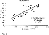
図6は種々の切除カテーテルの種々の温度においてカテーテル切除の時に到達する損傷の深さを本発明によって得られる電位値の時間的積分値に対してプロットしたグラフである。
本発明を最初に図1、図3及び図4を参照しながら好ましい実施例について説明する。最も簡単な本発明の実施態様を説明するために、まず図1に電圧測定装置1で得られた電圧信号が示されている。測定装置には低域通過濾波器2が前置接続されている。
低域通過濾波器の電極c、dにおける電圧タップは、たとえば、PCT/DE96/00638明細書に記載されているように、双極カテーテルのプラチナ電極に接続されている。
しかし、カテーテル3は本発明を実施するために通常なんらの付加的なカテーテル温度検知手段たとえば温度センサーも必要としない。ただし、そのような温度センサーの使用が本発明によって除外されるものではない。
カテーテル電極aとbにおいて電圧をピックアップするかわりに、電圧を1つまたは複数の中性電極4とカテーテル3の電極a及びbの一方との間で検出することもできるしまたはそれぞれのカテーテル電極a及びbの場所について検出することもできる。
本発明の第一の実施態様の低域通過濾波器2はHameg HM 1007型の保存オシロスコープに接続されている。このオシロスコープは公知の態様で時間的に変化する電圧推移を二次元表示する装置である。
まず、図3に示した測定組立体によって図1に示した時間的に変化する電圧推移の信号波形が得られた。グラフの時間軸は20秒TIME/DIVで、電圧は10ミリボルトVOLTS/DIVで目盛られていた。基準信号U0の最初の低い平らな部分5は血液流内にカテーテル3が存在する時の電圧を表しそしてカテーテル3が組織7と接触するとただちに明らかに認識される信号フランク部6が現れる。
信号肩部8は信号フランク部6が急激に上昇した後ほぼ平らにのびる。この信号肩部は時間的変調を示すものであり、その変調は中性電極4または電極aに関してカテーテル電極aと組織7との間の機械的カテーテル−組織接触に原因を帰することができるか、あるいはまた、カテーテルの場所において電気的電位を惹起する化学物質の発生と移動に関係しているものである。
カテーテルが組織から離れると、下降する信号フランク部9が現れ、この部分は基準信号0よりもやや高い基準信号U2に次第に減衰移行する。
信号フランクの急激な上昇部分6と下降部分9は高い確実性をもってカテーテル/組織接触の発生と終了を示す。
図1に示した信号波形を得るために使用されたシステムの構成が図3に定置測定組立体の形で図式的に示されており、これは標準化と目盛り較正のために使用できる。HF−発生器11は前記で引用したPCT出願明細書に記載されている装置に接続されておりそしてカテーテル3の電極にパルス化された高周波電力を供給する。上記引用装置は複数の切除電極を有するカテーテル3に高周波電力を制御しながら与えるための装置である。
しかし、本発明の別の実施態様として、高周波電力を時間的に連続してカテーテル3に供給することもできる。
槽13の内部には中性電極4と組織7が置かれており、この組織にカテーテル3を用いて切除が行われる。槽13内には患者の体内で支配的な環境を模擬するために血液または他の適当な液体が満たされている。
中性電極4およびカテーテル3の電極aとbはプラチナでメッキされるかまたはプラチナからつくられる。これらは使用直前に、カテーテルならびに中性電極4に実質的なんらの表面残存物も残さないように、ホルマリンまたはホルムアルデヒドで洗浄される。
ホルマリンまたはホルムアルデヒドによる洗浄が、非常に良好で再現性のある測定結果をもたらし、その洗浄効果は多数日間にわたって非常に確実に追認できることが判明している。ただし、本発明の範囲内で、実質的に残存物のない電極表面を得るために他の洗浄法を使用することもできる。
さらにまた、本発明による電圧あるいは、カテーテル電極と組織が接触状態に入った時および/または接触状態を持続しいる時に出現する類似の電圧を発生することのできる他の金属または化学物質の使用も除外されない。このためには、本発明の意味において、ただし制限なく一般的に、カテーテル切除中に本発明による電位を惹起する遊離基または少なくとも化学物質を生成することが前提となる。さらに、高周波電力と組織との相互作用が強力である場合に上記した物質が組織から多量に出るのであれば、本発明の装置は組織内で生じた損傷または外傷作用に関する情報を直接得ることができる。
次に図5を参照すると、時間的に電位測定箇所で検知された温度に対して本発明による電位値をプロットしたグラフが示されている。点線で示した温度値と実線で示した電位値23との一致状態は予想どおり予め与えられたモデルと良く一致する。なぜならば、化学的電位もほとんど温度に依存しているからである。しかし、処置後に、図5の右側に示されているように、温度が下がった時、電位は高められた値U2まで下がるだけである。このことは前記した化学物質の存在によって良く説明できる。
機械的接触の消失と温度の落下との識別は供給された電力を知り、それからしきい値を求めることによって容易に可能である。そのしきい値を最小期待電圧値として、そしてそれを下回った時に切除エネルギーの供給を遮断する。
電位発生の説明モデルをさらに明らかに支持するものが図6に示されている。すなわち、そのグラフによればHF−切除の時に患者の組織に生じる損傷の深さが生じる電位の時間的積分に依存することがわかる。20℃以上の切除カテーテルの温度範囲の全体にわたって、すなわち、55℃を下回る切除温度から75℃を上回る切除温度までの範囲においては、両者の値は互いに良く相関している。したがって、公知の特性のカテーテルにおいては、多くの場合、処置の成り行きについて適当な情報を得るためには電位の時間的積分だけで十分となり、付加的に温度値を検知する必要はなくなる。
この種のカテーテルでは温度センサーをなくすことができ、したがってカテーテルは有利なコストで、より小さな直径をもって簡単に製造することができる。さらに、本発明の範囲内で、より簡単な実施態様が可能となる。すなわち、温度の測定を行うことなく、切除高周波発生器の供給電力を予め定めた最高温度を決して超過しないように制限することができる。これによって、さらに、望ましくない凝集の抑制ができかつまた組織の蒸発を防止することができる。
測定の精度すなわち図6に示した数値の相関度を上げるために、評価装置15によって供給電力で加重したまたはそれと機能的に結合された電位値測定を、好ましくはリアルタイムで、実施することもできる。
いま1つの本発明による実施態様が図2に示されている。この実施態様では、前記に引用したPCT出願明細書に記載されているパルス駆動高周波発生器11がカテーテル3ならびにそのカテーテル電極aとbに接続されている。カテーテル電極aとbはそれ自体が切除電極であるか、またはそれらの近傍に配置された各切除電極に従属する測定電極であり、これには低域通過濾波器2が接続されている。この低域通過濾波器は高周波信号ならびにハム信号ノイズを濾過排除する。後置接続されている評価装置15は電圧測定装置1を含む。このシステムは第一実施態様の場合と同様に、場合によっては存在する付加的な切除工程への電流または他の測定工程からの電流を実質的にもはや測定不能な値まで抑制するために、少なくとも100kΩ以上、好ましくは数MΩの高オーミック入力抵抗を有する。本発明の意味において、高抵抗電圧測定とは、切除実施中またはたとえばEKG信号の測定においてはもはや出てこない、あるいは、もはや存在が実証できない電圧の測定のことである。
特に好ましい実施態様の場合、たとえば制御装置としてのパーソナルコンピュータに接続しうる保存オシロスコープの場合、入力抵抗は約1MΩでありそしてその入力容量は30pFを上回らない。
電圧測定装置1で得られた測定データは評価装置15に記録され、その中に保存される。これらのデータはリアルタイムで、あるいは、評価装置15のメモリーから読出して2次元形式で表示装置21に表示することができ、比較の目的で、あるいは、処置成果を評価するためなどの目的で再生される。
この場合、表示は瞬間的電圧信号として、ビームダイアグラム(棒グラフ)として、あるいは他の、処置を行っている医師にとって作業上好都合な方法で行われる。
さらに、評価装置15に付属している制御装置16は、測定された電圧値が予め定められた限界値Ug117以下まで低下した時、カテーテルまたはその周囲が加熱されて所望されない切除が起こらないように、HF−発生器11から供給される電力を遮断または低減する働きをすることができる。限界値Ug117はその時々に供給される瞬間的切除電力または積分された供給切除電力すなわち与えられる切除エネルギーにより変更しうるものであり、したがってきわめて正確に設定することができる。これによって凝集物質によるカテーテルの汚れを大幅に減らしまたは回避することができる。
さらに加えて、制御装置16は切除工程の初めに、いま1つの限界値Ug218を超過した時にHF−発生器11から供給される電力の積分を開始する。積分は限界値Ug117を下回るまで、あるいは、他の任意に設定した値を下回るまで続けられる。しかして、組織内へのエネルギー供給量が把握される。これによって、処置を行っている医師が切除効果についての情報を得ることが可能となる。さらに切除の成果の情報を向上しまたは補正するため、HF−発生器11から供給された電力の積分を増幅させた電圧信号の高さをもって実施することも本発明の範囲内である。
HF−発生器11から供給された電力の積分の際に、瞬間的電圧U1に依存するその他の関数値を一緒に考慮に入れることも同じく本発明の範囲内である。他の関数の例は標準測定の際に求められた、標準化カテーテル3または個別のカテーテル3のための損傷作用を表にした関数値などである。
ある特定のカテーテルタイプまたは個々のカテーテルのために得られたパラメータ数値を損傷作用を知るために利用すると、損傷の深さも供給されたエネルギーの関数として表すことができそして損傷進行を停止するために使用できる。これによって、それぞれのカテーテル電極の処置を行う医師に、生じる損傷の局部的に異なる深さあるいは特定の深さと長さを定め、制御装置16にそれを設定しそしてその後、処置中自動的に切り換える可能性が与えられる。
自動停止の代わりに、処置を行っている医師に光信号または音響信号を与えることもできる。こうすれば、処置の間医師を支援することができそして、たとえば、EKG−データによる切除のさらなる実施を妨げることもない。
非常に高いエネルギーが供給されると、処置されるべき組織の内部で蒸発または気化が起こる。このような場合、一般に電圧ピークが形成される。これは図1でピーク20として測定される。このようなピークは、本発明に従って、電位推移曲線の時間的微分および/または絶対値によって、あるいは制御値としての2つの測定値を変数とする関数によって、高周波エネルギーの供給を中断するためまたは少なくとも当該状態を局所的に軽減するために利用することができる。さらにまた、制御装置16を外部計算機またはパーソナルコンピュータ19で実現することも本発明の範囲内である。
同様に、本発明は高周波カテーテル切除のみに限定されるものではない。その時々の処置の成り行きを監視するために、他のほとんどのカテーテル切除法の場合においても好結果をもって使用できるものである。
参照数字リスト
1 電圧測定装置
2 低域通過濾波器
3 カテーテル
4 中性電極
5 基準信号U0
6 信号フランク部(上昇側)
7 組織
8 信号肩部
9 信号フランク部(下降側)
10 高められた基準信号U2
11 HF−発生器
12 切除−制御装置
13 槽
14 血液、液体
15 評価装置
16 制御装置
17 限界値Ug
18 限界値Ug
19 パーソナルコンピュータ
20 ピーク
21 表示装置 DESCRIPTION The present invention relates to a method and system for detecting contact with a patient's vasculature, in particular a catheter inserted into a patient's blood vessel, and also the interaction of radio frequency energy with patient's tissue. It relates to a method and system for detection.
In many medical applications or procedures, it is crucial that the physician accurately senses contact between the instrument and the patient's tissue, maintains that contact, and often records it. This is because the outcome of the treatment often depends substantially on this.
In particular, in the case of catheter ablation, the desired treatment effect is generally achieved only if contact between the ablation catheter and the patient's tissue to be treated can be ensured during the entire duration of the supplied ablation power.
Conventionally, in order to detect catheter-tissue contact, it has been performed to measure the resistance between at least two catheter electrodes or between a catheter electrode and a neutral electrode attached to the patient's body. This method, however, is disadvantageous, especially in the case of radiofrequency-catheter ablation where resistance measurements are principally made in relation to the current through the region to be measured. That is, during ablation, additional current flows through that region, which can be very hindered, for example, in detecting EKG signals. The use of DC resistance measurement methods to avoid high frequency signals that affect EKG detection results in an undesirable electrolysis effect that further adds chemical load to the patient. Moreover, the resistance measurement method as a whole is difficult to implement and is prone to failure. That is, the influence of corrosion and surface contamination can obstruct the flow of current or cause erroneous measurement results. Moreover, such a situation just occurs in the medical use area. This is because the patient's blood or bodily fluids in this region have salts and aggregates that interact undesirably with the electrode or contact surface. Furthermore, the impedance measurement method makes it difficult to determine tissue contact during excision. This is because many factors can affect the impedance value.
The object of the present invention is therefore to eliminate the drawbacks mentioned above and to better detect contact between the catheter and the patient's tissue.
Quite surprisingly, this object is achieved by the method and system of the present invention.
Unexpectedly, we often find that a voltage develops between the electrodes when they are in contact with the patient's tissue, especially when blood is flowing, especially during HF ablation. I discovered. The preferably metal electrode of the ablation catheter generates a voltage signal as shown, for example, in FIG. This signal is obtained with the measurement assembly shown in FIG. 2 according to the present invention.
Surprisingly, the inventors have found that a catheter inserted into a blood vessel first generates a very weak voltage signal, indicated by U 0 in the drawing, and then a rapid voltage rise occurs when the catheter electrode contacts the tissue. I found out. The resulting voltage signal is a measure of the quality of catheter-tissue contact due to its instantaneous value or amplitude, and can be detected without the use of additional extraneous current. Thus, no electrolysis takes place in the method of the invention, and therefore other measurements such as recording of EKG signals are not adversely affected.
Furthermore, it was confirmed that the voltage measurement according to the present invention is clearly superior to the measurement data obtained from the conventional resistance measurement. That is, firstly, impedance measurements during conventional ablation can only conclude the condition of catheter contact with tissue, but voltage is a very accurate measure of catheter electrode contact with tissue. Second, this voltage signal is generated with little time delay and is therefore optimal for real-time measurements.
Even more surprisingly, it was confirmed that the height of the measurement signal is very accurately related to the temperature of the tissue, in particular the temperature of the tissue that rises during ablation. Using the parallel measurement method, it has been found that the temperature value of the tissue in contact with the catheter can be measured with an accuracy of ± 1 ° C. according to the present invention. Furthermore, even with simple means, for example, a high resistance voltage measuring device, measurement with an accuracy of ± 2 ° C. is already possible. In this case, the temperature is in a regular linear relationship with the measured voltage, so that standardized voltage measurements can be subordinate to the ablation catheter itself or a group of similarly structured catheters.
Since the voltage can be measured in principle even when there is no current, for example, by applying a counter voltage with a uniform height or by an ultrahigh resistance measurement amplifier, the contact resistance of the contact within the measurement range is It is much less important than with all measurement methods. Therefore, the system according to the present invention and the method according to the present invention are much less disturbing than conventional methods and can be used with high reliability. Furthermore, thermal resistance (passage resistance) and the heat capacity of the catheter itself have little effect on temperature measurement accuracy and speed.
Even more surprisingly, it has been found that the results are significantly improved in catheter ablation itself. For example, when the catheter temperature is used as a reference value, and thus as a measure for energy supply, as in the case of conventional catheter temperature control, the catheter may be at a relatively low temperature, eg, only about 40 ° C. If the catheter is in very narrow contact with the tissue so that most of the ablation energy is introduced at the point of contact, it can cause obvious damage to the tissue.
The simple temperature control by a conventional temperature sensor should not detect the damage in such a case. Furthermore, it will be appreciated that even if the catheter temperature is high, the damage or excision action is negligible if the contact between the catheter and the tissue is very poor. In both cases, conventional methods and devices make an incorrect or incorrect perception of the outcome of the procedure.
On the other hand, in the case of the present invention, it is always confirmed that the energy supply is substantially performed in the tissue by the generation and detection of the voltage signal. Therefore, in the case of the present invention, the power supplied from the catheter is directly and accurately provided for the treatment action. Furthermore, after a rapid voltage rise detects catheter / tissue contact, the absolute value of the voltage signal can be used for very accurate temperature control.
Furthermore, the resulting voltage signal can be used for controlling or monitoring the ablation itself. For example, in the case of high-frequency ablation, if the voltage signal is detected during high-frequency power supply and the supply of high-frequency power is cut off or at least reduced when the signal level drops or exceeds, the high-frequency power is substantially reduced by the patient. It is always guaranteed to be delivered into the tissue, and overall better treatment results can be obtained with a cooler catheter electrode.
Furthermore, it is advantageous to integrate the voltage signal, thereby obtaining information about the interaction, i.e. the working temperature and the treatment time.
Furthermore, according to the invention, the contamination of the catheter due to agglomeration is very small due to the low catheter temperature that is possible for an accurate measurement according to the invention. Therefore, the interruption of treatment due to such soiling and thus the associated patient load is avoided.
By interrupting or at least reducing the supply of high-frequency power during sudden increases or drops in potential values, evaporation of the treated tissue is also avoided or at least significantly limited. This is because very rapid adjustments are possible and unwanted tissue overheating no longer occurs.
Furthermore, surprisingly, the potential or voltage signal according to the present invention during radiofrequency ablation is always very reliably detected regardless of whether the application of the radiofrequency signal is continuous or pulsed for ablation. It was confirmed that it was possible. The RF power output from the catheter is integrated over time as long as it is above a preset limit that ensures that catheter / tissue contact exists, and the integrated power is delivered to the tissue up to that point. If calculated as ablation energy, not only can the physician performing the procedure be informed of the progress of the procedure, but also the high frequency when a predetermined energy value is reached using a suitably programmed controller. The procedure can be terminated automatically by shutting off or reducing power. This provides a higher degree of treatment certainty than was possible with the conventional method. This makes it possible for the first time to detect the ablation effect by integrating the supplied power, even during the procedure, and to display it in real time to the treating physician.
Furthermore, in another embodiment of the present invention, the treating physician can pre-set the tissue depth, the pre-set depth being dependent on the time integral of the measured potential. In this case, the system according to the present invention can terminate the entire ablation process after reaching the setpoint, and in the case of a catheter with a large number of electrodes, the local dependent part that has reached the setpoint in the catheter is determined. It is also possible to cut off or introduce less power into that part.
In a preferred embodiment of the invention for this, when a catheter with a large number of ablation electrodes is used, the signal data can be allocated, detected, calculated and displayed on the individual electrodes. Then, the progress of the treatment can be locally programmed for each treatment site, and the treatment can be terminated locally. As a result, the optimum data for the treatment can be set in parallel locally before the treatment starts, and the optimum treatment can be performed for each patient.
Hereinafter, the present invention will be described in more detail with reference to the accompanying drawings.
In the attached drawings:
FIG. 1 shows the signal waveform of a voltage according to the present invention that occurs during a time-limited catheter electrode-tissue contact in a system having an indifferente platinum electrode and a platinum-catheter electrode.
FIG. 2 is a schematic illustration for practicing the present invention using one catheter and one device, and the system corresponds to that described for example in PCT / DE96 / 00638, but Further modifications are made in accordance with the present invention.
FIG. 3 is a block diagram of an experiment-measurement system for performing standardization or graduation calibration and measurement data acquisition using a porcine heart.
FIG. 4 shows a low-pass filter that can be used with an oscilloscope to obtain a voltage signal according to the present invention.
FIG. 5 is a graph plotting potential values obtained by the present invention during catheter ablation in a living heart against locally parallel temperature values obtained at the ablation catheter.
FIG. 6 is a graph plotting the depth of damage reached at the time of catheter ablation at various temperatures for various ablation catheters versus the time integral of potential values obtained by the present invention.
The invention will first be described with respect to a preferred embodiment with reference to FIGS. 1, 3 and 4. FIG. In order to explain the simplest embodiment of the present invention, first, a voltage signal obtained by the voltage measuring apparatus 1 is shown in FIG. A low-
The voltage taps at the electrodes c, d of the low-pass filter are connected to the platinum electrode of the bipolar catheter, for example as described in PCT / DE96 / 00638.
However, the catheter 3 usually does not require any additional catheter temperature sensing means, such as a temperature sensor, to practice the present invention. However, the use of such a temperature sensor is not excluded by the present invention.
Instead of picking up the voltage at the catheter electrodes a and b, the voltage can be detected between one or more
The low-
First, the signal waveform of the time-varying voltage shown in FIG. 1 was obtained by the measurement assembly shown in FIG. The time axis of the graph was 20 seconds TIME / DIV, and the voltage was scaled at 10 millivolts VOLTS / DIV. The first low
The
When the catheter leaves the tissue, a descending signal flank 9 appears, which gradually attenuates and transitions to a reference signal U 2 slightly higher than the
The sharply rising portion 6 and falling portion 9 of the signal flank indicate the occurrence and termination of catheter / tissue contact with high certainty.
The system configuration used to obtain the signal waveform shown in FIG. 1 is shown schematically in FIG. 3 in the form of a stationary measurement assembly, which can be used for standardization and calibration. The HF-
However, as another embodiment of the present invention, high frequency power can be supplied to the catheter 3 continuously in time.
A
The
It has been found that cleaning with formalin or formaldehyde gives very good and reproducible measurement results, and that the cleaning effect can be very reliably confirmed over many days. However, other cleaning methods can be used to obtain an electrode surface that is substantially free of residue within the scope of the present invention.
Furthermore, the use of a voltage according to the present invention or other metals or chemicals capable of generating a similar voltage that appears when the catheter electrode and tissue enter into contact and / or remain in contact. Not excluded. For this purpose, in the sense of the present invention, but generally without limitation, it is presupposed that free radicals or at least chemical substances are generated that cause the potential according to the present invention during catheter ablation. Furthermore, if the above-mentioned substances are released in large quantities from the tissue when the interaction between the high-frequency power and the tissue is strong, the device of the present invention can directly obtain information on the damage or trauma effect occurring in the tissue. it can.
Next, referring to FIG. 5, there is shown a graph in which the potential value according to the present invention is plotted with respect to the temperature detected at the potential measurement point in time. The coincidence state between the temperature value indicated by the dotted line and the
The distinction between the loss of mechanical contact and the drop in temperature is easily possible by knowing the power supplied and then determining the threshold. The ablation energy supply is cut off when the threshold value is set to the minimum expected voltage value and below that value.
What more clearly supports the explanatory model of potential generation is shown in FIG. That is, the graph shows that the depth of damage that occurs in the patient's tissue during HF-resection depends on the temporal integration of the potential. Both values correlate well with each other over the entire temperature range of the ablation catheter above 20 ° C., ie in the range from ablation temperatures below 55 ° C. to ablation temperatures above 75 ° C. Therefore, in the case of a catheter having a known characteristic, in many cases, the temporal integration of the potential is sufficient to obtain appropriate information about the outcome of the treatment, and it is not necessary to detect the temperature value additionally.
With this type of catheter, the temperature sensor can be eliminated, so that the catheter can be easily manufactured with a smaller diameter at an advantageous cost. Furthermore, simpler embodiments are possible within the scope of the invention. That is, it is possible to limit the power supplied to the ablation high-frequency generator so as not to exceed a predetermined maximum temperature without measuring the temperature. This can further suppress undesirable aggregation and also prevent tissue evaporation.
In order to increase the accuracy of the measurement, i.e. the degree of correlation of the values shown in FIG. 6, a potential value measurement weighted by the power supply by the
Another embodiment according to the invention is shown in FIG. In this embodiment, the pulse-driven high-
In a particularly preferred embodiment, for example, a storage oscilloscope that can be connected to a personal computer as a controller, the input resistance is about 1 MΩ and its input capacitance does not exceed 30 pF.
Measurement data obtained by the voltage measuring device 1 is recorded in the
In this case, the display is performed as an instantaneous voltage signal, as a beam diagram (bar graph), or in any other manner convenient for the physician performing the procedure.
Furthermore, the
In addition, the
It is also within the scope of the present invention to take into account other function values that depend on the instantaneous voltage U 1 together when integrating the power supplied from the
Using the parameter values obtained for a particular catheter type or individual catheter to know the damage effect, the depth of damage can also be expressed as a function of the supplied energy and to stop the damage progression Can be used. This allows the physician performing the treatment of each catheter electrode to define a locally different depth or specific depth and length of the resulting damage, set it in the
As an alternative to automatic stopping, an optical or acoustic signal can be provided to the treating physician. In this way, the physician can be assisted during the procedure and does not prevent further performance of the excision with, for example, EKG-data.
When very high energy is supplied, evaporation or vaporization occurs within the tissue to be treated. In such a case, a voltage peak is generally formed. This is measured as
Similarly, the present invention is not limited to high frequency catheter ablation alone. It can be used successfully in the case of most other catheter ablation procedures to monitor the progress of the procedure from time to time.
Reference number list 1
6 Signal flank (upward side)
7
10 Enhanced reference signal U 2
11 HF-
18 Limit value U g
19
Claims (13)
少なくとも1つのカテーテル電極(a,b)における電圧を測定する装置(1)を有し、
前記カテーテル電極(a,b)と別の電極(a,b,4)との間の電圧を測定し、
前記別の電極は処置を受ける患者の身体と接触している中性電極(4)であるか、またはカテーテル(3)に取りつけられた別の電極(a,b)であり、
電圧測定が、実質的に切除またはEKG信号の測定の障害となる電流をまったく生じないような高抵抗で実施され、かつ、
前記電圧測定装置(1)は、前記カテーテル(3)が患者の組織と接触したときに電圧の上昇を測定する、
ことを特徴とするシステム。In a system for detecting contact between a catheter inserted into a patient's blood vessel and the patient's tissue having at least a catheter electrode and another electrode,
Having a device (1) for measuring the voltage at at least one catheter electrode (a, b);
Measuring the voltage between the catheter electrode (a, b) and another electrode (a, b, 4);
Said another electrode is a neutral electrode (4) in contact with the body of the patient to be treated, or another electrode (a, b) attached to the catheter (3),
The voltage measurement is performed at a high resistance so as not to produce any current that substantially impedes the ablation or measurement of the EKG signal; and
The voltage measuring device (1) measures an increase in voltage when the catheter (3) comes into contact with a patient's tissue ,
A system characterized by that.
Applications Claiming Priority (5)
| Application Number | Priority Date | Filing Date | Title |
|---|---|---|---|
| DE19713234 | 1997-04-01 | ||
| DE19740976A DE19740976A1 (en) | 1997-04-01 | 1997-09-17 | Method and device for detecting catheter-tissue contact during HF surgical catheter ablation |
| DE19740976.8 | 1997-09-17 | ||
| DE19713234.0 | 1997-09-17 | ||
| PCT/DE1998/000932 WO1998043547A2 (en) | 1997-04-01 | 1998-04-01 | Method and device for detecting catheter-tissue contact and interaction with tissue during catheter ablation |
Publications (3)
| Publication Number | Publication Date |
|---|---|
| JP2001522265A JP2001522265A (en) | 2001-11-13 |
| JP2001522265A5 JP2001522265A5 (en) | 2005-11-24 |
| JP4105238B2 true JP4105238B2 (en) | 2008-06-25 |
Family
ID=26035367
Family Applications (1)
| Application Number | Title | Priority Date | Filing Date |
|---|---|---|---|
| JP54106898A Expired - Fee Related JP4105238B2 (en) | 1997-04-01 | 1998-04-01 | System for detecting catheter-tissue contact and detecting tissue interaction during catheter resection |
Country Status (10)
| Country | Link |
|---|---|
| US (1) | US6304776B1 (en) |
| EP (1) | EP0971636B1 (en) |
| JP (1) | JP4105238B2 (en) |
| AT (1) | ATE307536T1 (en) |
| AU (1) | AU740503B2 (en) |
| CA (1) | CA2285342C (en) |
| DE (1) | DE59813142D1 (en) |
| DK (1) | DK0971636T3 (en) |
| ES (1) | ES2249832T3 (en) |
| WO (1) | WO1998043547A2 (en) |
Families Citing this family (70)
| Publication number | Priority date | Publication date | Assignee | Title |
|---|---|---|---|---|
| US7097641B1 (en) | 1999-12-09 | 2006-08-29 | Cryocath Technologies Inc. | Catheter with cryogenic and heating ablation |
| US6546270B1 (en) | 2000-07-07 | 2003-04-08 | Biosense, Inc. | Multi-electrode catheter, system and method |
| US6408199B1 (en) | 2000-07-07 | 2002-06-18 | Biosense, Inc. | Bipolar mapping of intracardiac potentials with electrode having blood permeable covering |
| US6569160B1 (en) | 2000-07-07 | 2003-05-27 | Biosense, Inc. | System and method for detecting electrode-tissue contact |
| US7789876B2 (en) * | 2000-08-14 | 2010-09-07 | Tyco Healthcare Group, Lp | Method and apparatus for positioning a catheter relative to an anatomical junction |
| US7819870B2 (en) * | 2005-10-13 | 2010-10-26 | St. Jude Medical, Atrial Fibrillation Division, Inc. | Tissue contact and thermal assessment for brush electrodes |
| US7972298B2 (en) | 2004-03-05 | 2011-07-05 | Hansen Medical, Inc. | Robotic catheter system |
| US7824408B2 (en) | 2004-08-05 | 2010-11-02 | Tyco Healthcare Group, Lp | Methods and apparatus for coagulating and/or constricting hollow anatomical structures |
| US20070016272A1 (en) | 2004-09-27 | 2007-01-18 | Thompson Russell B | Systems and methods for treating a hollow anatomical structure |
| WO2006066205A2 (en) | 2004-12-19 | 2006-06-22 | Ade Corporation | System and method for inspection of a workpiece surface using multiple scattered light collectors |
| WO2006069313A1 (en) * | 2004-12-20 | 2006-06-29 | Vnus Medical Technologies, Inc. | Systems and methods for treating a hollow anatomical structure |
| DE102005025946A1 (en) | 2005-01-26 | 2006-08-03 | Erbe Elektromedizin Gmbh | High frequency surgical device for treating monopolar coagulation of biological tissue, has control unit controlling generator to supply voltage to target region and producing switching off signal if target input reaches final value |
| US7625372B2 (en) | 2005-02-23 | 2009-12-01 | Vnus Medical Technologies, Inc. | Methods and apparatus for coagulating and/or constricting hollow anatomical structures |
| WO2007005976A1 (en) | 2005-07-01 | 2007-01-11 | Hansen Medical, Inc. | Robotic catheter system |
| DE202006021215U1 (en) | 2005-07-21 | 2013-11-08 | Covidien Lp | Apparatus for treating a hollow anatomical structure |
| US8679109B2 (en) | 2005-10-13 | 2014-03-25 | St. Jude Medical, Atrial Fibrillation Division, Inc. | Dynamic contact assessment for electrode catheters |
| US8672936B2 (en) | 2005-10-13 | 2014-03-18 | St. Jude Medical, Atrial Fibrillation Division, Inc. | Systems and methods for assessing tissue contact |
| US20070093697A1 (en) | 2005-10-21 | 2007-04-26 | Theranova, Llc | Method and apparatus for detection of right to left shunting in the cardiopulmonary vasculature |
| US20180311071A1 (en) | 2005-10-21 | 2018-11-01 | Daniel R. BURNETT | Method and apparatus for peritoneal oxygenation |
| ATE548985T1 (en) | 2005-10-27 | 2012-03-15 | St Jude Medical Atrial Fibrill | SYSTEMS FOR ASSESSING ELECTRODE CONTACT |
| US8190238B2 (en) | 2005-12-09 | 2012-05-29 | Hansen Medical, Inc. | Robotic catheter system and methods |
| US7879029B2 (en) | 2005-12-30 | 2011-02-01 | Biosense Webster, Inc. | System and method for selectively energizing catheter electrodes |
| US20070244371A1 (en) * | 2006-04-04 | 2007-10-18 | Nguyen Hoa D | Phlebectomy illumination device and methods |
| CN100421617C (en) * | 2006-08-16 | 2008-10-01 | 中山市创源电子有限公司 | Human body impedance measuring apparatus and fat meter using same |
| US8226648B2 (en) | 2007-12-31 | 2012-07-24 | St. Jude Medical, Atrial Fibrillation Division, Inc. | Pressure-sensitive flexible polymer bipolar electrode |
| US7883508B2 (en) | 2006-12-29 | 2011-02-08 | St. Jude Medical, Atrial Fibrillation Division, Inc. | Contact-sensitive pressure-sensitive conductive composite electrode and method for ablation |
| US7955326B2 (en) * | 2006-12-29 | 2011-06-07 | St. Jude Medical, Atrial Fibrillation Division, Inc. | Pressure-sensitive conductive composite electrode and method for ablation |
| US10085798B2 (en) * | 2006-12-29 | 2018-10-02 | St. Jude Medical, Atrial Fibrillation Division, Inc. | Ablation electrode with tactile sensor |
| US9579483B2 (en) | 2006-12-29 | 2017-02-28 | St. Jude Medical, Atrial Fibrillation Division, Inc. | Pressure-sensitive conductive composite contact sensor and method for contact sensing |
| US8374673B2 (en) | 2007-01-25 | 2013-02-12 | Warsaw Orthopedic, Inc. | Integrated surgical navigational and neuromonitoring system having automated surgical assistance and control |
| US7987001B2 (en) | 2007-01-25 | 2011-07-26 | Warsaw Orthopedic, Inc. | Surgical navigational and neuromonitoring instrument |
| CA2684807A1 (en) * | 2007-04-05 | 2008-10-16 | Velomedix, Inc. | Automated therapy system and method |
| EP2167000A1 (en) | 2007-07-09 | 2010-03-31 | Velomedix, Inc | Hypothermia devices and methods |
| US8396533B2 (en) * | 2007-08-21 | 2013-03-12 | Siemens Aktiengesellschaft | Method and system for catheter detection and tracking in a fluoroscopic image sequence |
| US8211102B2 (en) * | 2007-12-21 | 2012-07-03 | St. Jude Medical, Atrial Fibrillation Division, Inc. | Contact sensing flexible conductive polymer electrode |
| US8500731B2 (en) * | 2007-12-21 | 2013-08-06 | St. Jude Medical, Atrial Fibrillation Division, Inc. | Adjustable length flexible polymer electrode catheter and method for ablation |
| US20100168557A1 (en) * | 2008-12-30 | 2010-07-01 | Deno D Curtis | Multi-electrode ablation sensing catheter and system |
| US8948476B2 (en) | 2010-12-20 | 2015-02-03 | St. Jude Medical, Atrial Fibrillation Division, Inc. | Determination of cardiac geometry responsive to doppler based imaging of blood flow characteristics |
| US8900150B2 (en) | 2008-12-30 | 2014-12-02 | St. Jude Medical, Atrial Fibrillation Division, Inc. | Intracardiac imaging system utilizing a multipurpose catheter |
| US9610118B2 (en) | 2008-12-31 | 2017-04-04 | St. Jude Medical, Atrial Fibrillation Division, Inc. | Method and apparatus for the cancellation of motion artifacts in medical interventional navigation |
| US9254123B2 (en) | 2009-04-29 | 2016-02-09 | Hansen Medical, Inc. | Flexible and steerable elongate instruments with shape control and support elements |
| US20100280328A1 (en) * | 2009-05-01 | 2010-11-04 | Tyco Healthcare Group, Lp | Methods and systems for illumination during phlebectomy procedures |
| US8936631B2 (en) | 2010-01-04 | 2015-01-20 | Covidien Lp | Apparatus and methods for treating hollow anatomical structures |
| US9237961B2 (en) * | 2010-04-23 | 2016-01-19 | Medtronic Vascular, Inc. | Stent delivery system for detecting wall apposition of the stent during deployment |
| WO2012006625A2 (en) | 2010-07-09 | 2012-01-12 | Velomedix, Inc. | Method and apparatus for pressure measurement |
| US20120191107A1 (en) | 2010-09-17 | 2012-07-26 | Tanner Neal A | Systems and methods for positioning an elongate member inside a body |
| WO2012100211A2 (en) | 2011-01-20 | 2012-07-26 | Hansen Medical, Inc. | System and method for endoluminal and transluminal therapy |
| US20130030363A1 (en) | 2011-07-29 | 2013-01-31 | Hansen Medical, Inc. | Systems and methods utilizing shape sensing fibers |
| US8700133B2 (en) | 2012-06-18 | 2014-04-15 | Smart Iv Llc | Apparatus and method for monitoring catheter insertion |
| US9597482B2 (en) | 2012-06-18 | 2017-03-21 | Smart Iv Llc | Apparatus and method for monitoring catheter insertion |
| DE102012220658A1 (en) * | 2012-11-13 | 2014-05-15 | Olympus Winter & Ibe Gmbh | Electrosurgical instrument for coagulation or ablation of body tissue |
| US20140148673A1 (en) | 2012-11-28 | 2014-05-29 | Hansen Medical, Inc. | Method of anchoring pullwire directly articulatable region in catheter |
| US9326822B2 (en) | 2013-03-14 | 2016-05-03 | Hansen Medical, Inc. | Active drives for robotic catheter manipulators |
| US20140277334A1 (en) | 2013-03-14 | 2014-09-18 | Hansen Medical, Inc. | Active drives for robotic catheter manipulators |
| US20140276936A1 (en) | 2013-03-15 | 2014-09-18 | Hansen Medical, Inc. | Active drive mechanism for simultaneous rotation and translation |
| US9408669B2 (en) | 2013-03-15 | 2016-08-09 | Hansen Medical, Inc. | Active drive mechanism with finite range of motion |
| US10682175B2 (en) * | 2013-11-06 | 2020-06-16 | Biosense Webster (Israel) Ltd. | Using catheter position and temperature measurement to detect movement from ablation point |
| US10046140B2 (en) | 2014-04-21 | 2018-08-14 | Hansen Medical, Inc. | Devices, systems, and methods for controlling active drive systems |
| CN109069840B (en) | 2016-02-04 | 2022-03-15 | 心脏起搏器股份公司 | Delivery system with force sensor for leadless cardiac devices |
| US10463439B2 (en) | 2016-08-26 | 2019-11-05 | Auris Health, Inc. | Steerable catheter with shaft load distributions |
| US11241559B2 (en) | 2016-08-29 | 2022-02-08 | Auris Health, Inc. | Active drive for guidewire manipulation |
| US11426126B2 (en) | 2019-05-23 | 2022-08-30 | Biosense Webster (Israel) Ltd. | Indicating electrode contact |
| US20210077180A1 (en) | 2019-09-12 | 2021-03-18 | Biosense Webster (Israel) Ltd. | Balloon Catheter with Force Sensor |
| US20220183748A1 (en) | 2020-12-16 | 2022-06-16 | Biosense Webster (Israel) Ltd. | Accurate tissue proximity |
| US11864844B2 (en) | 2020-12-22 | 2024-01-09 | Biosense Webster (Israel) Ltd. | Distal end assembly guidance |
| US20220370145A1 (en) | 2021-05-24 | 2022-11-24 | Biosense Webster (Israel) Ltd. | Gesture based selection of portion of catheter |
| US20230008606A1 (en) | 2021-07-06 | 2023-01-12 | Biosense Webster (Israel) Ltd. | Contact assessment for balloon catheter |
| US20230028867A1 (en) | 2021-07-23 | 2023-01-26 | Biosense Webster (Israel) Ltd. | Accurate tissue proximity |
| US20230157569A1 (en) | 2021-11-22 | 2023-05-25 | Biosense Webster (Israel) Ltd. | Mapping System with Real Time Electrogram Overlay |
| US20230210437A1 (en) | 2021-12-30 | 2023-07-06 | Biosense Webster (Israel) Ltd. | Intuitive Mapping System |
Family Cites Families (8)
| Publication number | Priority date | Publication date | Assignee | Title |
|---|---|---|---|---|
| DE3911416A1 (en) | 1989-04-07 | 1990-10-11 | Delma Elektro Med App | ELECTRO-SURGICAL HIGH-FREQUENCY DEVICE |
| US5419767A (en) * | 1992-01-07 | 1995-05-30 | Thapliyal And Eggers Partners | Methods and apparatus for advancing catheters through severely occluded body lumens |
| US5462545A (en) * | 1994-01-31 | 1995-10-31 | New England Medical Center Hospitals, Inc. | Catheter electrodes |
| US5562722A (en) * | 1994-03-14 | 1996-10-08 | Medical Evaluation Devices & Instruments Corp. | Multiple electrode catheter |
| US5697925A (en) | 1995-06-09 | 1997-12-16 | Engineering & Research Associates, Inc. | Apparatus and method for thermal ablation |
| DE29519651U1 (en) | 1995-12-14 | 1996-02-01 | Muntermann Axel | Device for linear radio frequency catheter ablation of endomyocardial tissue |
| US6066139A (en) * | 1996-05-14 | 2000-05-23 | Sherwood Services Ag | Apparatus and method for sterilization and embolization |
| US5704908A (en) * | 1996-10-10 | 1998-01-06 | Genetronics, Inc. | Electroporation and iontophoresis catheter with porous balloon |
-
1998
- 1998-04-01 JP JP54106898A patent/JP4105238B2/en not_active Expired - Fee Related
- 1998-04-01 WO PCT/DE1998/000932 patent/WO1998043547A2/en active IP Right Grant
- 1998-04-01 DK DK98928114T patent/DK0971636T3/en active
- 1998-04-01 AU AU80088/98A patent/AU740503B2/en not_active Ceased
- 1998-04-01 AT AT98928114T patent/ATE307536T1/en not_active IP Right Cessation
- 1998-04-01 ES ES98928114T patent/ES2249832T3/en not_active Expired - Lifetime
- 1998-04-01 US US09/402,222 patent/US6304776B1/en not_active Expired - Lifetime
- 1998-04-01 CA CA002285342A patent/CA2285342C/en not_active Expired - Fee Related
- 1998-04-01 EP EP98928114A patent/EP0971636B1/en not_active Expired - Lifetime
- 1998-04-01 DE DE59813142T patent/DE59813142D1/en not_active Expired - Lifetime
Also Published As
| Publication number | Publication date |
|---|---|
| AU8008898A (en) | 1998-10-22 |
| ES2249832T3 (en) | 2006-04-01 |
| DK0971636T3 (en) | 2006-03-20 |
| ATE307536T1 (en) | 2005-11-15 |
| WO1998043547A3 (en) | 1999-01-21 |
| AU740503B2 (en) | 2001-11-08 |
| US6304776B1 (en) | 2001-10-16 |
| EP0971636B1 (en) | 2005-10-26 |
| CA2285342C (en) | 2007-06-19 |
| DE59813142D1 (en) | 2005-12-01 |
| CA2285342A1 (en) | 1998-10-08 |
| WO1998043547A2 (en) | 1998-10-08 |
| EP0971636A2 (en) | 2000-01-19 |
| JP2001522265A (en) | 2001-11-13 |
Similar Documents
| Publication | Publication Date | Title |
|---|---|---|
| JP4105238B2 (en) | System for detecting catheter-tissue contact and detecting tissue interaction during catheter resection | |
| AU2018203829B2 (en) | Real-time prediction of steam-pop events during ablation | |
| EP2206472B1 (en) | Engergy delivery algorithm filter pre-loading | |
| US9326814B2 (en) | System and method for predicting lesion size shortly after onset of RF energy delivery | |
| EP2213255B1 (en) | Energy delivery algorithm for medical devices | |
| EP2206473B1 (en) | An energy delivery algorithm for medical devices based on maintaining a fixed position on a tissue electrical conductivity v. temperature curve | |
| JP6246525B2 (en) | Machine learning in the determination of catheter electrode contact | |
| US6696844B2 (en) | Apparatus and method for real time determination of materials' electrical properties | |
| EP2499982B1 (en) | Energy-based ablation completion algorithm | |
| JP6866147B2 (en) | Sheath visualization method using impedance position identification and magnetic information | |
| JP2009518151A (en) | Evaluation of electrode coupling for tissue ablation | |
| EP2842507B1 (en) | Determining absence of contact for a catheter | |
| CN108403208B (en) | Estimation of tissue thickness | |
| WO2007010391A1 (en) | Apparatus for operations of arterial hemostasis | |
| EP3932350A1 (en) | Impedance controlled rf transseptal perforation | |
| EP3932351A1 (en) | Contact sensing for an ablation catheter | |
| JP2022056403A (en) | Detecting electrode contact using absolute and relative thresholds | |
| EP4079243A1 (en) | Sensing for a catheter | |
| JP2023171320A (en) | Impedance-based ablation index for IRE |
Legal Events
| Date | Code | Title | Description |
|---|---|---|---|
| A521 | Request for written amendment filed |
Free format text: JAPANESE INTERMEDIATE CODE: A523 Effective date: 20050316 |
|
| A621 | Written request for application examination |
Free format text: JAPANESE INTERMEDIATE CODE: A621 Effective date: 20050316 |
|
| RD05 | Notification of revocation of power of attorney |
Free format text: JAPANESE INTERMEDIATE CODE: A7425 Effective date: 20050316 |
|
| RD04 | Notification of resignation of power of attorney |
Free format text: JAPANESE INTERMEDIATE CODE: A7424 Effective date: 20050316 |
|
| A131 | Notification of reasons for refusal |
Free format text: JAPANESE INTERMEDIATE CODE: A131 Effective date: 20061107 |
|
| A977 | Report on retrieval |
Free format text: JAPANESE INTERMEDIATE CODE: A971007 Effective date: 20061024 |
|
| A601 | Written request for extension of time |
Free format text: JAPANESE INTERMEDIATE CODE: A601 Effective date: 20070131 |
|
| A602 | Written permission of extension of time |
Free format text: JAPANESE INTERMEDIATE CODE: A602 Effective date: 20070402 |
|
| A521 | Request for written amendment filed |
Free format text: JAPANESE INTERMEDIATE CODE: A523 Effective date: 20070506 |
|
| A02 | Decision of refusal |
Free format text: JAPANESE INTERMEDIATE CODE: A02 Effective date: 20070703 |
|
| A521 | Request for written amendment filed |
Free format text: JAPANESE INTERMEDIATE CODE: A821 Effective date: 20071002 |
|
| A521 | Request for written amendment filed |
Free format text: JAPANESE INTERMEDIATE CODE: A523 Effective date: 20071031 |
|
| A911 | Transfer to examiner for re-examination before appeal (zenchi) |
Free format text: JAPANESE INTERMEDIATE CODE: A911 Effective date: 20071220 |
|
| TRDD | Decision of grant or rejection written | ||
| A01 | Written decision to grant a patent or to grant a registration (utility model) |
Free format text: JAPANESE INTERMEDIATE CODE: A01 Effective date: 20080305 |
|
| A61 | First payment of annual fees (during grant procedure) |
Free format text: JAPANESE INTERMEDIATE CODE: A61 Effective date: 20080327 |
|
| R150 | Certificate of patent or registration of utility model |
Free format text: JAPANESE INTERMEDIATE CODE: R150 |
|
| FPAY | Renewal fee payment (event date is renewal date of database) |
Free format text: PAYMENT UNTIL: 20110404 Year of fee payment: 3 |
|
| LAPS | Cancellation because of no payment of annual fees |