JP4046897B2 - Image input apparatus and control method thereof - Google Patents
Image input apparatus and control method thereof Download PDFInfo
- Publication number
- JP4046897B2 JP4046897B2 JP18688099A JP18688099A JP4046897B2 JP 4046897 B2 JP4046897 B2 JP 4046897B2 JP 18688099 A JP18688099 A JP 18688099A JP 18688099 A JP18688099 A JP 18688099A JP 4046897 B2 JP4046897 B2 JP 4046897B2
- Authority
- JP
- Japan
- Prior art keywords
- image
- template
- printing
- unit
- Prior art date
- Legal status (The legal status is an assumption and is not a legal conclusion. Google has not performed a legal analysis and makes no representation as to the accuracy of the status listed.)
- Expired - Lifetime
Links
Images


Classifications
-
- H—ELECTRICITY
- H04—ELECTRIC COMMUNICATION TECHNIQUE
- H04N—PICTORIAL COMMUNICATION, e.g. TELEVISION
- H04N1/00—Scanning, transmission or reproduction of documents or the like, e.g. facsimile transmission; Details thereof
- H04N1/00127—Connection or combination of a still picture apparatus with another apparatus, e.g. for storage, processing or transmission of still picture signals or of information associated with a still picture
- H04N1/00278—Connection or combination of a still picture apparatus with another apparatus, e.g. for storage, processing or transmission of still picture signals or of information associated with a still picture with a printing apparatus, e.g. a laser beam printer
-
- H—ELECTRICITY
- H04—ELECTRIC COMMUNICATION TECHNIQUE
- H04N—PICTORIAL COMMUNICATION, e.g. TELEVISION
- H04N1/00—Scanning, transmission or reproduction of documents or the like, e.g. facsimile transmission; Details thereof
- H04N1/21—Intermediate information storage
- H04N1/2104—Intermediate information storage for one or a few pictures
- H04N1/2112—Intermediate information storage for one or a few pictures using still video cameras
- H04N1/2125—Display of information relating to the still picture recording
-
- H—ELECTRICITY
- H04—ELECTRIC COMMUNICATION TECHNIQUE
- H04N—PICTORIAL COMMUNICATION, e.g. TELEVISION
- H04N1/00—Scanning, transmission or reproduction of documents or the like, e.g. facsimile transmission; Details thereof
- H04N1/21—Intermediate information storage
- H04N1/2104—Intermediate information storage for one or a few pictures
- H04N1/2112—Intermediate information storage for one or a few pictures using still video cameras
- H04N1/2137—Intermediate information storage for one or a few pictures using still video cameras with temporary storage before final recording, e.g. in a frame buffer
- H04N1/2141—Intermediate information storage for one or a few pictures using still video cameras with temporary storage before final recording, e.g. in a frame buffer in a multi-frame buffer
-
- H—ELECTRICITY
- H04—ELECTRIC COMMUNICATION TECHNIQUE
- H04N—PICTORIAL COMMUNICATION, e.g. TELEVISION
- H04N2101/00—Still video cameras
-
- H—ELECTRICITY
- H04—ELECTRIC COMMUNICATION TECHNIQUE
- H04N—PICTORIAL COMMUNICATION, e.g. TELEVISION
- H04N2201/00—Indexing scheme relating to scanning, transmission or reproduction of documents or the like, and to details thereof
- H04N2201/0008—Connection or combination of a still picture apparatus with another apparatus
- H04N2201/001—Sharing resources, e.g. processing power or memory, with a connected apparatus or enhancing the capability of the still picture apparatus
Landscapes
- Engineering & Computer Science (AREA)
- Multimedia (AREA)
- Signal Processing (AREA)
- Television Signal Processing For Recording (AREA)
- Facsimiles In General (AREA)
- Editing Of Facsimile Originals (AREA)
- Studio Devices (AREA)
- Accessory Devices And Overall Control Thereof (AREA)
- Record Information Processing For Printing (AREA)
Description
【0001】
【発明の属する技術分野】
本発明は、画像入力装置により取得される画像の印刷に関する。
【0002】
【従来の技術】
ディジタルスチルカメラなどの画像入力装置、パーソナルコンピュータなどのホスト情報処理装置、および、プリンタから構成される印刷システムでは、撮影により取得した画像データを印刷する際にユーザは以下の操作を行う。
(1)シリアルケーブルなどの通信手段によりコンピュータと画像入力装置とを接続し、撮影画像をコンピュータへ転送し、画像データファイルとしてハードディスクなどに格納し、
(2)フォトレタッチ用のソフトウェアを起動し、
(3)フォトレタッチ用のソフトウェアによりハードディスクなどに格納された画像データファイルを開き、
(4)フォトレタッチ用のソフトウェアのメニューから「印刷」を選択することで、現在開いている画像データファイルが表す画像をプリンタに印刷させる。
【0003】
【発明が解決しようとする課題】
上記のような印刷システムにおいては、コンピュータの扱いに不慣れなユーザにとってはコンピュータの操作が難しく、上記の操作手順を正確に行えない場合も有る。このような問題に鑑み、「ダイレクトプリンタ」などと呼ばれるプリンタが開発された。このダイレクトプリンタは、直接、画像入力装置に接続することができ、画像入力装置およびプリンタを操作するだけで撮影画像の印刷が可能である。このため、コンピュータの操作に不慣れなユーザでも、簡単に撮影画像を印刷することができる。
【0004】
しかしながら、ダイレクトプリンタは、プリンタ自身にコントローラ、画像処理用のディジタル信号プロセッサ(DSP)、および、画像入力装置との通信を行うモジュールなどが必要で高価である。さらに、通信モジュールは、画像入力装置の通信規約に適合または準拠する必要があり、通信が可能な画像入力装置が限定されるという問題がある。
【0005】
さらに、プリンタ自体が色補正、ディザ、パレットの作成、明度補正、各色成分のゲイン補正、コントラスト補正、色温度補正およびガンマ補正などの画像処理を行う場合、快適な印刷スピードを得るために高速な演算装置や多くのメモリを必要とし、プリンタのコストが大幅に上げる問題もある。
【0006】
本発明は、取得または記憶された画像にテンプレート画像を合成した画像の印刷を容易かつ安価に行うこと目的とする。
【0007】
【課題を解決するための手段】
本発明は、前記の目的を達成する一手段として、以下の構成を備える。
【0008】
本発明にかかる画像入力装置は、画像を取得する取得手段と、前記取得した画像をメモリに記憶させる記憶制御手段と、テンプレート画像を記憶する情報処理装置と通信を行う通信手段と、前記テンプレート画像に対応する縮小画像を記憶するテンプレート画像記憶手段と、前記縮小画像から合成すべき縮小画像を選択するための選択手段と、前記取得または記憶された画像に、前記選択された縮小画像を合成した合成画像を表示する表示手段と、前記合成画像の印刷要求を入力するための入力手段とを有し、前記通信手段は、前記印刷要求が入力されると、印刷を指示するコマンド、前記取得または記憶された印刷すべき画像、および、前記選択された縮小画像を示すIDを前記情報処理装置へ送信して、前記情報処理装置に、前記印刷すべき画像に前記 ID に対応するテンプレート画像を合成した印刷イメージを生成させることを特徴とする。
【0011】
本発明にかかる制御方法は、画像を取得する取得手段、前記取得した画像をメモリに記憶させる記憶制御手段、テンプレート画像を記憶する情報処理装置と通信を行う通信手段、および、前記テンプレート画像に対応する縮小画像を記憶するテンプレート画像記憶手段を有する画像入力装置の制御方法であって、前記縮小画像から選択された合成すべき縮小画像の選択指示を入力し、前記取得または記憶された画像に、前記選択された縮小画像を合成した合成画像を表示し、前記合成画像の印刷要求を入力し、前記印刷要求が入力されると、印刷を指示するコマンド、前記取得または記憶された印刷すべき画像、および、前記選択された縮小画像を示すIDを前記通信手段を介して前記情報処理装置へ送信して、前記情報処理装置に、前記印刷すべき画像に前記 ID に対応するテンプレート画像を合成した印刷イメージを生成させることを特徴とする。
【0013】
【発明の実施の形態】
以下、本発明にかかる一実施形態の画像入力装置、情報処理装置および印刷システムを図面を参照して詳細に説明する。
【0014】
【第1実施形態】
[概要]
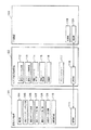
図1は本発明にかかる一実施形態の画像入力装置および印刷システムの構成例を示すブロック図である。以下、図1を参照しながら、本実施形態の画像入力装置および印刷システムについて説明する。
【0015】
図1に示されるように、画像入力装置101は、ユーザの指示入力に従い撮影を行って、撮影された画像を画像データ記憶部109へ格納する撮影部104、ユーザからの印刷要求を受け付ける印刷コマンドユーザ入力部105、ユーザから印刷要求が入力されると、この要求に従い、予め定められた形式の印刷コマンドを作成する通信コマンド作成部106、作成された印刷コマンドを接続されたホスト情報処理装置102に送信する通信部111、画像データ記憶部109に格納されている画像データおよびその他の情報をユーザの要求に応じて表示する画像表示部110、ホスト情報処理装置102から受信された通信コマンドの解析を行う通信コマンド解析部107、並びに、通信コマンド解析部107の解析結果に応じて、コマンドに対応した処理を実行する通信コマンド実行部108から構成される。
【0016】
また、ホスト情報処理装置102は、画像入力装置101や印刷装置103とコマンドおよびデータの送受信を行うための通信部118、画像入力装置101から受信されたコマンドの解析を行うホスト通信コマンド解析部113、画像入力装置101へ送信すべきコマンドを作成するホスト通信コマンド作成部113、ホスト通信コマンド解析部113の解析結果が印刷を要求するコマンドを示す場合に印刷シーケンスを実行する印刷シーケンス実行部114、画像入力装置101から受信された印刷画像データから記録紙119上に印刷されるべき印刷イメージを形成する印刷イメージ形成部115、受信された印刷画像データや印刷イメージ、その他の情報を記憶する記憶部116、並びに、印刷装置103との規約に従い印刷装置103を駆動し、印刷イメージ形成部115により形成された印刷イメージを通信部118を介して印刷装置103へ送信するプリンタドライバ117を有する。
【0017】
なお、現在一般に販売されているプリンタには、プリンタが接続されるパーソナルコンピュータ(PC)のオペレーティングシステム(OS)ごとにプリンタドライバ(ソフトウェア)が付属している。このため、PC上で稼動するアプリケーションソフトウェアなどは、印刷装置との低レベルな通信規約などをとくに意識せずに、OSの備えるアプリケーションプログラムインタフェイス(API)を介して、プリンタドライバを起動し制御することによって、画像などを印刷することができる。つまり、図1に示すプリンタドライバ117は、このような一般的なプリンタドライバであって構わない。また、印刷装置103は、通信部120を介して受信される印刷イメージを記録紙119上に可視形成するものであり、現在一般的に普及しているプリンタで構わない。
【0018】
上記の構成において、撮影済みの一枚以上の画像を印刷したい場合、ユーザは印刷コマンドユーザ入力部105により印刷要求を入力する。この要求により、通信コマンド作成部106は、ホスト通信コマンド解析部113との間の規約に従う印刷要求コマンドを作成し、このコマンドを通信部111を介して送信する。ホスト情報処理装置102においては、通信部118を介して受信されるコマンドをホスト通信コマンド解析部113が解析し、印刷シーケンス実行部114による印刷シーケンスが実行される。なお、画像データ記憶部109に複数の画像が記憶されている場合は、画像表示部110に表示されている画像を印刷すべき画像とすることもできるが、予め画像入力装置101を操作することにより、複数枚の画像を印刷すべき画像に指定することもでき、印刷すべき画像の指定方法はどのような方法であっても構わない。
【0019】
印刷シーケンス実行部114の印刷シーケンスにおいては、まず、ホスト通信コマンド作成部113により印刷画像データの転送要求コマンド(印刷画像転送要求コマンド)IDC_GET_PRINT_IMGが作成される。転送要求コマンドは通信部111へ送信され、ホスト情報処理装置102は画像データが送信されてくるのを待つ状態になる。
【0020】
IDC_GET_PRINT_IMGコマンドを受信した画像入力装置101においては、通信コマンド解析部107により転送要求コマンドが解析され、通信コマンド実行部108が起動される。そして、画像データ記憶部109に格納された画像から印刷すべき一枚以上の画像が選択され、それらの画像に対応する画像データが印刷画像データとして通信部111を介してホスト情報処理装置102へ転送される。
【0021】
印刷画像データを受信した印刷シーケンス実行部114は、印刷イメージ形成部115を起動し、受信した印刷画像データを印刷するのに好ましいレイアウトの印刷イメージを形成させる。好ましいレイアウトの一例としては、印刷すべき画像データとして二枚分の横長画像が受信され、かつ、A4の記録紙に印刷する場合は、縦に二枚の画像を並べたイメージを形成するなどが考えられるが、この限りではない。さらに、印刷イメージ形成部115は、好ましい印刷結果を得るために、画像入力装置101および印刷装置103における色などの再現特性の違いに即した色補正、ディザ、パレット作成などの画像処理も行う。
【0022】
さらに、印刷シーケンス実行部114は、プリンタドライバ117を起動し、形成された印刷イメージをプリンタドライバ117へ渡し、この印刷イメージに対応する画像をプリントするように要求する。この印刷要求を受けたプリンタドライバ117は、通信部118を介して印刷装置103を駆動し、記録紙119上に印刷イメージを印刷させる。
【0023】
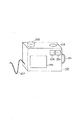
[画像入力装置]
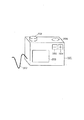
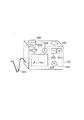
図2は本実施形態における画像入力装置101であるディジタルスチルカメラの外観図である。
【0024】
図2において、202は動作モードを設定するモード設定ダイアルで、ダイアル位置に応じたカメラ101の動作モードが設定される。本実施形態のカメラ101は、動作モードとして撮影モード、再生モードおよび印刷モードをもつ。また、本実施形態のカメラ101は、画像表示部110として、ディジタルスチルカメラとして一般的なLCD203を用いる。本実施形態においては、印刷モードの際、LCD203に画像データ記憶部109に格納されている撮影済み画像の内の一枚が表示される。
【0025】
204は「+」ボタン、205は「-」ボタンで、LCD203に表示すべき画像をユーザが選択するためのものである。印刷モード時にこれらボタンを押すことにより、画像データ記憶部109に所定の順序で記憶されている画像の中から、現在LCD203に表示されている画像の次または前の画像が選択される。
【0026】
206はレリーズボタンで、このボタンが押されることにより、カメラ101に対して撮影指示や印刷要求が入力される。つまり、印刷モードの場合は、レリーズボタン206が押されることにより印刷要求が入力されるので、この場合はレリーズボタン206が印刷コマンドユーザ入力部105として機能する。さらに詳しく説明すると、レリーズボタン206が押されると、画像の印刷を指示するコマンドIDC_PRINT_IMGが通信コマンド作成部106により作成され、そのコマンドは通信部111を介してホスト情報処理装置102へ送信される。
【0027】
207は通信ケーブルで、通信部111とホスト情報処理装置102とを介在して、通信媒体として機能する。例えば、本実施形態における通信部111などにはUSB(Universal Serial Bus)コントローラを用い、通信ケーブル207にはUSBケーブルを用いる。勿論、USBの代わりにIEEE1394に適合または準拠するシリアルバスを用いることも可能である。
【0028】
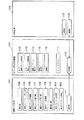
[ホスト情報処理装置]
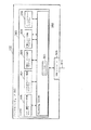
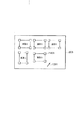
図3は本実施形態におけるホスト情報処理装置102の構成例を示すブロック図である。
【0029】
図3において、ホスト情報処理装置102は、例えば、一般に普及しているパーソナルコンピュータ(PC)であり、マイクロソフト社のWindows98(R)などのオペレーティングシステム(OS)302上で各種プログラムを実行可能な環境にある。従って、図1に示す各機能部に対応するソフトウェアプログラムを、図3に示すように、DRAM303上にロードし、図示しないCPUが各プログラムを実行することによって、各機能部を実現することができる。PC102の構成としては、図3には示さないが、キーボード、ディスプレイおよびマウスなどの周辺機器が接続されるとともに、ハードディスクなどの記憶手段を備えている。
【0030】
ここで、本実施形態に採用されるWindows98(R)オペレーティングシステムの「プッシュモデル」と呼ばれるアーキテクチャについて若干説明する。
【0031】
Windows98(R)では、プッシュモデルと呼ばれるアーキテクチャを採用している。プッシュモデルでは、PC102に備えられているUSB(などの外部接続)端子にUSBケーブルを接続し、USBケーブルの他端にプッシュモデルデバイスを接続すると、プッシュモデルデバイスが接続されたことを検知して、各デバイスに対応付けされたプログラム(対応プログラム)を起動したり、OSの起動時にプッシュモデルデバイスが接続されていれば、対応プログラムを自動起動する仕組みになっている。さらに、各デバイスから送られてくるコマンド(イベント)をイベントモニタ(Still image event monitor)304が監視していて、イベントが発生すると、このイベントをコントロールセンタ(Still Image Control Center)へ送信する。各イベントに対応するプログラムは、このコントロールセンタを介して、コマンド(イベント)を取得することができる構造になっている。なお、本発明において、「イベント」とは「コマンド」の一種であり、とくにユーザが画像入力装置101に対して行った入力に対応して発行されるコマンドを「イベント」と呼ぶことにする。
【0032】
本実施形態においては、プッシュモデルのアーキテクチャを採用するため、画像入力装置101はプッシュモデルデバイスとしての機能を備えるものとする。なお、Windows98(R)のプッシュモデルを取り上げたが、これに限らず、ユーザが印刷要求コマンドを入力した時点で、ホスト通信コマンド解析部113がホスト情報処理装置102内で稼動していて、通信部118により受信されたコマンドを取得し解析できればよい。従って、例えば、通信部118が受信するデータを監視するデーモンプログラムを常に稼動しておき、印刷要求コマンドの認識をトリガとして印刷シーケンスを実行するような独自の構造を実現することもできる。
【0033】
図3において、305はUSBコントローラで、通信部118の実施形態である。306はホスト通信コマンド作成プログラムで、ホスト通信コマンド作成部113の実施形態である。307はホスト通信コマンド解析プログラムで、ホスト通信コマンド解析部113の実施形態である。308は印刷シーケンス実行プログラムで、印刷シーケンス実行部114の実施形態である。309は印刷イメージ形成プログラムで、印刷イメージ形成部115の実施形態である。310はプリンタドライバプログラムで、プリンタドライバ117の実施形態である。311はUSBケーブルで、ディジタルスチルカメラ101やプリンタ103などの外部機器と接続するためのものである。
【0034】
[印刷装置]
一般に、プリンタはプリンタドライバプログラムが添付された形態で販売されている。通常、プリンタドライバプログラムはプリンタの機種ごとに、通信手段の種類ごとに、さらにオペレーティングシステムごとに用意され供給される。本実施形態のプリンタドライバ117は、このような一般的なものでよく、本実施形態におけるプリンタドライバプログラム310は、印刷装置103用のUSBかつWindows98(R)用のプリンタドライバプログラムである。また、本実施形態におけるプリンタドライバプログラム310は、USBコントローラ305を介して印刷装置103に画像データを転送し、印刷要求を行うものであり、必要に応じて色補正、画像フォーマット変換、送信データのパケット化、印刷装置103とのデータ転送におけるネゴシエーションなどの処理も行う。これらの機能も、市販のプリンタに添付されるプリンタドライバプログラムの機能と同様のものである。
【0035】
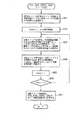
[印刷処理]
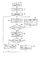
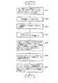
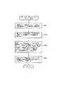
図4はPC102における印刷処理の手順例を示すフローチャートである。カメラ101とPC102とがUSBケーブルで接続された状態で、ユーザがPC102の電源を投入すると、PC102は図4に示す処理を開始する。
【0036】
まず、ステップS1でOS302が起動され、ステップS2でOS302の初期化処理が行われる。この時点で、OS302はUSBケーブルを介してカメラ101が接続されていることを検知し、ホスト通信コマンド作成プログラム306およびホスト通信コマンド解析プログラム307を起動する。
【0037】
次にステップS3において、イベントモニタ304がUSBケーブルを介して受信されるイベントをポーリングし、イベント待ち状態になる。イベントモニタ304が何らかのイベントを検知すると処理はステップS4へ進む。
【0038】
ステップS4では、受信されたイベントがカメラ101からのものかどうかが判別される。カメラ101以外の機器から受信されたイベントである場合、処理はステップS5へ進む。また、カメラ101から受信されたイベントである場合、処理はステップS6へ進む。ステップS5では、イベントを発生した機器に対応するイベントハンドリングプログラムにより受信されたイベントに対応する処理が行われた後、ステップS3へ戻る。
【0039】
ステップS6で、ホスト通信コマンド解析プログラム307によりイベントの内容が解析された後、ステップS7において、受信されたイベントの内容に対応する処理への分岐が行われる。受信されたイベントがIDC_PRINT_IMG(ユーザが印刷コマンドユーザ入力部105によって印刷要求を入力した際にカメラ101から発行されるイベント)である場合はステップS8において、印刷シーケンス実行プログラム308による印刷シーケンスが実行された後、ステップS3へ戻る。また、受信されたイベントがIDC_PRINT_IMG以外のイベントである場合は、ステップS9において、そのイベントに対応する処理が行われた後、ステップS3へ戻る。なお、ステップS8における印刷シーケンス実行プログラム308による印刷シーケンスの詳細については後述する。
【0040】
[印刷要求イベントの発行手続]
図5はカメラ101による印刷要求イベントの発行手続の手順例を示すフローチャートである。ユーザが、レリーズボタン206を押すことにより処理が開始される。
【0041】
まず、ステップS11において、現在設定されているモードが印刷モードか否か、つまりモード設定ダイアル202が「印刷」の位置にあるかどうかが判別される。印刷モードではなく撮影モードの場合はステップS13で撮影処理が行われる。勿論、その他のモードの場合はそのモードに対応した処理が行われる。また、現在設定されているモードが印刷モードである場合はステップS12で、通信コマンド作成部106により印刷要求を示すコマンド(イベント)であるIDC_PRINT_IMGが作成され、通信部111を介してPC102へイベントが送信された後、印刷イベント発行処理が終了する。
【0042】
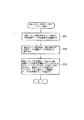
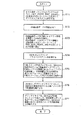
[印刷シーケンス]
図6は印刷シーケンス実行プログラム308による印刷シーケンス例を示すフローチャートである。
【0043】
印刷シーケンスでは、まず始めに、ステップS21においてカメラ101に対して印刷すべき画像データの転送要求を発行する。より具体的には、ホスト通信コマンド作成プログラム306が印刷すべき画像データの転送を要求するコマンドIDC_GET_PRINT_IMGを作成し、OS302およびUSBコントローラ305などを介して、このコマンドをカメラ101へと送信する。その後、ステップS22においてカメラ101から送られてくる印刷画像データの受信待ちになる。その間、カメラ101は、図7に示される印刷画像送信処理を行い、PC102への画像データ転送を開始する。この詳細については後述する。
【0044】
カメラ101の画像データ転送が開始されると、ステップS23において受信される印刷画像データを逐次DRAM303に格納する。印刷画像データの転送が完了するとステップS24へ処理を進め、OS302を介して、現在接続されている印刷装置103に対応したプリンタドライバプログラム310が起動される。
【0045】
次に、ステップS35で、印刷イメージ形成プログラム309が、DRAM303に格納されている印刷画像データをプリンタドライバプログラム310が処理可能な画像データ形式である印刷イメージへフォーマット変換し、DRAM303へ格納する。この際、プリンタ103の解像度、色および濃度などの印刷特性およびカメラ101の解像度、色および輝度などの画像特性を考慮した画像補正処理が実行されるとともに、印刷される画像のレイアウトおよびサイズなどを考慮して印刷イメージが形成される。
【0046】
Windows Operating Systemにおいては、グラフィックデバイスインタフェイス(GDI)という概念がある。プリント出力を要求するクライアントプログラムは、GDI関数を介して印刷装置103の機能を取得し、取得された機能に従いデバイスコンテキスト上に印刷イメージを構築する。このデバイスコンテキストに構築される画像データを本実施形態では印刷イメージとして扱うものとする。
【0047】
OS302を介して印刷イメージの形成が完了すると、ステップS26において、OS302を介してプリンタドライバプログラム310に対して、DRAM303に格納されている印刷イメージの印刷要求を発行する。印刷要求を受けたプリンタドライバプログラム310は、ステップS7において、OS302およびUSBコントローラ305を介して、印刷装置103とのコマンドの送受信を行い、印刷装置103を駆動し、印刷イメージを送信することによって、印刷イメージを記録紙119に印刷させる。印刷が終了すると印刷シーケンスは終了する。
【0048】
[印刷画像データの送信]
図7はカメラ101による印刷画像データの送信手順例を示すフローチャートである。
【0049】
カメラ101は、PC102からIDC_GET_PRINT_IMGを受信すると、ステップS31で、通信コマンド解析部107によりコマンドが解析され、印刷画像データの送信要求であると判別される。次に、ステップS2で、通信コマンド実行部108は、LCD203に現在表示されている画像に対応する画像データを印刷画像データとして画像データ記憶部109より取り出す。次に、ステップS3で、通信コマンド作成部106は、印刷画像データの送信開始を示す通知コマンドIDC_START_PRINT_IMGを作成し、通信部111を介して送信するとともに、これに続けて、印刷画像データを通信部111を介して送信する。印刷画像データの送信が完了すると処理は終了する。
【0050】
以上説明したように、本実施形態の印刷システムは市販のプリンタを利用した安価な構成であるが、ユーザは、画像入力装置で撮影した画像を印刷する場合に、コンピュータに対して複雑な操作を行うことなく、言い換えればカメラ101とPC102とを接続するだけで、撮影画像を容易、高画質、かつ、適切なレイアウトで印刷することができる。
【0051】
【第2実施形態】
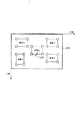
[構成]
図8は第2実施形態における画像入力装置101および印刷システムの基本的な構成例を示すブロック図である。第2実施形態の画像入力装置101は、第1実施形態の構成に加えて表示プロパティ設定部801および表示プロパティ記憶部802を有する。
【0052】
表示プロパティ設定部801は、ユーザが画像入力装置101のボタンやダイアルなどを操作することによって撮影済み画像が画像表示部110に再生表示される際の表示プロパティを設定するためのものである。表示プロパティの内容としては、明度、各色成分のゲイン、コントラスト、色温度およびガンマ値などがあげられる。TVモニタ、コンピュータディスプレイ、表示装置付きのディジタルカムレコーダなどでは、画像を表示する際の明度、各色成分のゲイン、コントラスト、色温度およびガンマ値などの表示プロパティを設定する設定部を有しているものが多い。本実施形態における表示プロパティ設定部801は、これらと同様のものであって構わない。
【0053】
表示プロパティ記憶部802は、ユーザが表示プロパティ設定部801によって設定した表示プロパティの値を記憶する。本実施形態における画像入力装置101は、表示プロパティ記憶部802に記憶されている表示プロパティを、印刷画像データとともにホスト情報処理装置102へ送信する。ホスト情報処理装置102は、印刷画像データに対して、表示プロパティに従った画像処理を施した後、印刷装置103に印刷を行わせる。これにより、ユーザは、ホスト情報処理装置102を操作することなく、画像入力装置101の画像表示部110に表示される再生画像の明るさ、コントラストおよび色合いを調節することで、好みの明るさ、コントラストおよび色合いを有する印刷画像を得ることができる。
【0054】
図9は第2実施形態における画像入力装置(ディジタルスチルカメラ)101の例を示す図である。第1実施形態のカメラ101に対して、明度設定ダイアル201が追加されている。明度設定ダイアル201は、表示プロパティ設定部801の実施形態であり、本ダイアルを回すことによりLCD203に表示された画像の表示明度を明るくしたり、暗くしたりすることができる。このように、本実施形態では、表示プロパティとして明度の設定が行えるものとする。
【0055】
また、第2実施形態のホスト情報処理装置102は、第1実施形態と同様であるが、印刷シーケンス実行プログラム308による印刷シーケンスおよび印刷イメージ形成プログラム309による印刷イメージ形成処理が第1実施形態と異なる。
【0056】
[印刷画像データおよび表示明度値の送信]
図10は第2実施形態におけるカメラ101の印刷画像データおよび表示明度値の送信手順例を示すフローチャートである。なお、本実施形態においては、表示プロパティとして明度値のみを設定および送信する例を説明するが、勿論、この限りではなく、他の表示プロパティとして各色成分のゲイン、コントラスト、色温度および/またはガンマ値など同様に設定および送信することができるのは明らかである。つまり、プロパティごとに行うべき画像処理の内容は、一般的なパーソナルコンピュータ用のフォトレタッチソフトウェアなどが行う各プロパティに対応した画像処理内容と何ら変わらない。
【0057】
図10において、ステップS41からS43の処理は、図7に示した第1実施形態におけるカメラ101による印刷画像データの送信手順(ステップS31からS33)と同様である。その後、ステップS44において、通信コマンド作成部106は、表示プロパティ記憶部802より表示プロパティとして表示明度値Lvalを取り出し、この値を通信部111を介して送信し処理を終了する。
【0058】
なお、本実施形態においては、明度設定ダイアル201を回すことにより、例えば表示明度値として-50から+50の値を設定できるものとし、-50をデフォルトの表示明度の50%の明度、+50をデフォルトの表示明度の150%の明度として画像表示部110に再生画像を表示するものとする。
【0059】
[印刷シーケンス]
本実施形態におけるPC102の印刷処理は、図4に示した第1実施形態の印刷処理とほぼ同じであるが、ステップS8で実行される印刷シーケンス実行プログラム308による印刷シーケンスが異なる。
【0060】
図11は第2実施形態における印刷シーケンス例を示すフローチャートである。
【0061】
図11において、ステップS51、S52、S54、S56およびS57については、図6に示した第1実施形態の印刷シーケンス(ステップS21、S22、S24、S26およびS27)と同様であるから、ここではステップS53およびS55の処理について説明する。
【0062】
ステップS53においては、印刷画像データを受信しDRAM303に格納するとともに、印刷画像データに引き続き受信される表示明度値Lvalを受信しDRAM303に格納する。また、ステップS55において、印刷イメージ形成プログラム309は、DRAM303に格納されている画像データに対して、DRAM303に格納されている表示明度値Lvalに基づく輝度値変換を行う。
【0063】
印刷イメージ形成プログラム309は、印刷画像データがYCrCb色空間で表現されているものとすると、Lval=-20の場合は、印刷画像データのすべての画素のYデータに対して80/100を乗算し、その結果を輝度値変換結果としてDRAM303に格納する。その後、色成分であるCrおよびCbデータに対する最適化処理およびページレイアウト処理などを施し、印刷装置103とOS302との規約に基づいたフォーマット変換などを行い、印刷画像データをDRAM303に格納する。
【0064】
このように、本実施形態によれば、第1実施形態と同様の効果が得られるほか、ユーザは、画像入力装置101のインタフェイスを操作することで、ホスト情報処理装置102によって実行される画像処理を設定することができる。従って、画像入力装置101の画像表示部110に表示される再生画像の明るさ、コントラストおよび色合いを調節することで、好みの明るさ、コントラストおよび色合いを有する印刷画像を容易に得ることができる。
【0065】
【第3実施形態】
[構成]
図12は第3実施形態における画像入力装置101および印刷システムの基本的な構成例を示すブロック図である。第3実施形態の画像入力装置101は、第1実施形態の構成に加えて、画像データ記憶部109に格納されている撮影済み画像の中からユーザが印刷を欲する一枚以上の画像(以下、簡単のため「印刷画像」と呼ぶ)を設定するための印刷画像設定部1301、印刷画像設定部1301によって設定された印刷画像のID情報を記憶する印刷画像ID記憶部1302、印刷画像ID記憶部1302に記憶されている印刷画像を印刷する際のレイアウトをユーザが入力、編集するための印刷レイアウト編集部1303、並びに、印刷レイアウト編集部1303によりユーザが入力、編集した印刷レイアウト情報を記憶する印刷レイアウト記憶部1304を有する。
【0066】
画像入力装置101は、ホスト情報処理装置102に対して、印刷画像データを送信するとともに、印刷レイアウト記憶部1304に記憶されている印刷レイアウト情報を送信し、印刷レイアウト情報に従う印刷をホスト情報処理装置102に要求する。また、この要求を受けたホスト情報処理装置102は、印刷イメージ形成部115の印刷イメージ形成処理において、印刷レイアウト情報に従い印刷イメージを形成する。
【0067】
また、第3実施形態のホスト情報処理装置102は、第1実施形態と同様であるが、印刷シーケンス実行プログラム308による印刷シーケンスおよび印刷イメージ形成プログラム309による印刷イメージ形成処理が第1実施形態と異なる。
【0068】
図13は第3実施形態におけるカメラ101の外観図である。
【0069】
図13において、1201はポインティングカーソルで、ユーザがプリントレイアウトを編集する際に位置を指示入力するためのものである。1202はユーザが上下左右の方向を指示するための十字キーで、この指示に従いポインティングカーソル1201がLCD203上を上下左右に移動する。1203は入力ボタンで、このボタンを押すことによって、ポインティングカーソル1201の現在位置を画像入力装置101にコマンド入力することができる。つまり、入力ボタン1203はマウスに備わっているボタンと同様の働きをする。1204はプリントマークボタンで、このボタンを押すことによって、現在表示されている画像を印刷画像または非印刷画像としてトグルすることができる。つまり、印刷画像として設定されていない画像は印刷画像に設定され、印刷画像として既に設定されている画像はその設定が解除される。
【0070】
なお、印刷モードにおいて、印刷画像が画像表示部110に表示されている場合、画像表示部110の左上に「P」の文字(以降「プリントマーク」と呼ぶ)が表示される。
【0071】
例えば100枚の画像が画像データ記憶部109に記憶されているとし、この内、画像1から画像5の五枚が印刷画像として設定されたとする。図14はこの場合の印刷画像ID記憶部1302内のメモリマップを示す図で、印刷すべき画像のID、画像1から画像5がインデックスとともに記憶されている。
【0072】
[レイアウト編集]
印刷モード、かつ、印刷画像ID記憶部1302が図14の状態でユーザがレリーズボタン206を押すと、カメラ101は画像1から画像5をLCD203に表示する。図15はこの時LCD203の表示状態例を示す図である。図15を用いて、ユーザが印刷レイアウト編集部1303に対してどのように印刷レイアウトの編集を行うのかを詳しく説明する。
【0073】
図15においてLCD203の全エリアは記録紙一枚の印刷可能領域を表し、画像1から画像5は、記録紙119上に図15に示されるレイアウトで印刷される。LCD203上の各画像の四隅にはハンドル1401が表示されていて、十字キー1202を操作することでカーソル1201をハンドル1401の位置まで移動し、ボタン1203を押したままカーソル1201を移動することにより、ハンドル1401の位置を移動することができる。ハンドル1401が移動された画像は、移動されたハンドル1401とその対角位置にあるハンドル1401とを二頂点とする長方形にフィットするように、拡大または縮小表示される。また、十字キー1202によりカーソル1201を所望する画像上に移動して、ボタン1203を押したままカーソル1201とともに画像を移動することにより、画像の位置を移動することができる。
【0074】
このようにして印刷レイアウト編集部1303によって編集された印刷レイアウトは、印刷レイアウト記憶部1304に記憶される。図16はユーザによってレイアウトが編集された後のLCD203の表示状態例を示す図である。
【0075】
また、図17は印刷レイアウト記憶部1304内のメモリマップを示す図で、印刷画像として印刷画像ID記憶部1302に記憶されているインデックス番号の画像の位置情報が、左上隅および右下隅のXY座標という形式で記憶されている。なお、本実施形態においては、図16に示すようにXおよびY軸を定め、記録紙119上における位置をミリメートル単位で表するものとする。図17に示すメモリマップ例は、ユーザが図16に示すレイアウトに編集した際の印刷レイアウト記憶部1304の記憶内容を示している。
【0076】
図14および図17に示す状態で、ユーザがレリーズボタン206を押すと、カメラ101は、第1実施形態の図5と同様に、印刷イベントIDC_PRINT_IMGを発行する。また、第1実施形態と同じく、PC102は、IDC_PRINT_IMGを受信した後、印刷画像データの送信を要求するコマンドIDC_GET_PRINT_IMGを発行する。カメラ101は、IDC_GET_PRINT_IMGを受信すると、図18に示す処理手順により印刷画像データおよび印刷レイアウト情報をPC102へ送信する。
【0077】
[印刷画像データおよび印刷レイアウト情報の送信]
図18はカメラ101による印刷画像データおよび印刷レイアウト情報の送信手順例を示すフローチャートである。
【0078】
カメラ101は、ホスト情報処理装置102からIDC_GET_PRINT_IMGを受信すると、ステップS61で通信コマンド解析部107によりコマンドを解析し、受信コマンドが印刷画像データおよび印刷レイアウト情報の送信要求であると認識する。ステップS62で、変数Index=1およびk=印刷画像枚数のように、変数の初期化が行われる。なお、図14に示すように印刷画像数が「5」の場合は変数kを「5」に初期化することになる。
【0079】
次に、ステップS63において、通信コマンド作成部106は、印刷画像ID記憶部1302を参照して、変数Indexにより示される画像のIDを取得する。そして、このIDに対応する画像データを画像データ記憶部109より読み出し、印刷画像データとして通信部111を介してホスト情報処理装置102へ送信する。
【0080】
次に、ステップS64において、通信コマンド実行部108は、印刷レイアウト記憶部1304を参照して、変数Indexに対応するレイアウト情報(座標情報)を左上XおよびY座標、右下XおよびY座標の順に取得して、これらの座標情報を、順次、通信部111を介してホスト情報処理装置102へ送信する。
【0081】
続いて、ステップS65で変数Indexをインクリメントし、ステップS66で変数Indexと変数kとを比較する。Index≦kならば未送信の画像が存在するのでステップS63へ戻る。また、Index>kならばすべての画像およびレイアウト情報を送信したことになるので、ステップ67で、通信コマンド作成部106は、印刷画像データおよびレイアウト情報の送信終了を示すメッセージコマンドIDM_END_PRINT_IMGを通信部111を介してホスト情報処理装置102へ送信する。その後、印刷画像データおよび印刷レイアウト情報の送信処理が終了する。
【0082】
[印刷シーケンス]
図19はホスト情報処理装置102の印刷シーケンス実行プログラム308による印刷シーケンスの手順例を示すフローチャートである。
【0083】
図19において、ステップS71、S72、S74、S76およびS77については、図6に示した第1実施形態の印刷シーケンス(ステップS21、S22、S24、S26およびS27)と同様であるから、ここではステップS73およびS75の処理について説明する。
【0084】
受信が開始されると、ステップS73で、カメラ101から送られてくる印刷画像データと、これに続き送られてくるレイアウト情報をDRAM303に格納する。印刷画像データおよび印刷レイアウト情報の送信終了を示すメッセージIDM_END_PRINT_IMGを受信するとステップS74へ処理を進める。
【0085】
ステップS75で、印刷イメージ形成プログラム309は、DRAM303に格納されているレイアウト情報に従い、DRAM303に格納されている印刷画像を一頁に配列した印刷イメージを形成し、印刷装置103およびOS302の規約に基づくフォーマット変換などを行い、印刷イメージとしてDRAM303に格納する。
【0086】
図20は上記の印刷シーケンスにより記録紙119上に印刷された画像の様子を示す図で、図16に示されるレイアウトに従って印刷されている。
【0087】
【第4実施形態】
[構成]
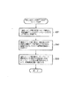
図21は第4実施形態における画像入力装置101および印刷システムの基本的な構成例を示すブロック図である。第4実施形態の画像入力装置101は、第1実施形態の構成に加えて、印刷の際に画像を縁取る枠画像などのテンプレート画像を複数記憶するテンプレート画像記憶部1801、および、複数のテンプレート画像の中から使用するテンプレート画像をユーザが選択するためのテンプレート画像選択部1802を有する。
【0088】
また、第4実施形態のホスト情報処理装置102は、画像入力装置101のテンプレート画像記憶部1801に記憶されたテンプレート画像に対応するテンプレート画像を記憶するホストテンプレート画像記憶部1803を有する。なお、テンプレート画像記憶部1801およびホストテンプレート画像記憶部1803には印刷に使用するテンプレート画像を記憶するようにしても構わないが、本実施形態では、テンプレート画像記憶部1801は、ホストテンプレート画像記憶部1803が記憶するテンプレート画像の縮小画像を記憶するものとする。この際の画像縮小率は、画像表示部110にテンプレート画像を表示した際に、ユーザがどのようなテンプレート画像かを認識できる程度の解像度を維持できるものであればよい。これにより、テンプレート画像記憶部1801の記憶容量を小さくすることができる。
【0089】
本実施形態におけるホスト情報処理装置102は、実施形態として第1実施形態と同じくパーソナルコンピュータを用いるものとする。そのブロック図は図3で示される第1の実施形態のものと同様である。異なる点は、印刷シーケンス実行プログラム308による印刷シーケンスの処理内容、印刷イメージ形成プログラム309による印刷イメージ形成処理の処理内容にある。また、本実施形態においては、ホストテンプレート画像記憶部1803は、DRAM303の一部分の記憶領域をもって実施するものとし、図3に図示されていないハードディスク装置より、DRAM303にテンプレート画像ファイルを読み込むことによって実現するものとする。
【0090】
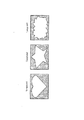
図22はテンプレート画像の一例を示す図で、本実施形態においては、Template 1、Template 2およびTemplate 3の三枚のテンプレート画像が記憶されているものとする。
【0091】
また、本実施形態におけるカメラ101の外観は図2に示した第1実施形態のカメラ101と同様であるが、本実施形態においては、モード設定ダイアル202によりテンプレート選択モードを設定できる。テンプレート選択モードにおいて、「+」キー204または「-」キー205を押すことにより、テンプレート画像記憶部1801に格納されているTemplate 1からTemplate 3がの何れかが、画像に合成されてLCD203に表示される。
【0092】
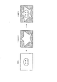
図23はテンプレート選択モードにおける画像合成の一例を示す図で、画像1が選択され、さらに、Template 2が選択されて、画像1とTemplate 2とが合成表示される様子を示している。
【0093】
[印刷要求イベントの発行]
図23の合成画像がLCD203に表示された状態で、ユーザがレリーズボタン206を押すと、カメラ101は図24に示す印刷要求イベント発行処理を実行する。
【0094】
まず、ステップS81で、現在のモードがテンプレート選択モードか否かを判別し、撮影モードであればステップS83で撮影処理を行う。また、テンプレート選択モードであればステップS82で、通信コマンド作成部106により印刷要求を示すコマンド(イベント)IDC_PRINT_IMGが作成され、通信部111を介してPC102へ送信された後、印刷イベント発行処理が終了する。勿論、他のモードの場合は、そのモードに対応した処理が行われる。
【0095】
[印刷画像データおよびテンプレートIDの送信]
図25はカメラ101による印刷画像データおよびテンプレートIDの送信手順例を示すフローチャートである。
【0096】
カメラ101は、PC102からIDC_GET_PRINT_IMGを受信すると、ステップS91において、通信コマンド解析部107によりコマンドを解析し、受信コマンドが印刷画像データおよびテンプレートIDの送信要求であることを認識する。
【0097】
次にステップS92で、通信コマンド実行部108は、LCD203に表示中の画像データを画像データ記憶部109より取り出し、印刷画像データとして通信部111を介してPC102へ送信する。
【0098】
次にステップS93で、通信コマンド実行部108は、現在LCD203に表示されているテンプレート画像のテンプレートIDを通信部111を介してPC102へ送信し、本処理は終了する。
【0099】
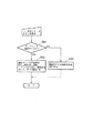
[印刷シーケンス]
図26はPC102の印刷シーケンス実行プログラム308による印刷シーケンスの処理手順例を示すフローチャートである。
【0100】
図26において、ステップS101、S104、S106およびS107については、図6に示した第1実施形態の印刷シーケンス(ステップS21、S24、S26およびS27)と同様であるから、ここではステップS102、S103およびS105の処理について説明する。
【0101】
PC102は、ステップS102で、カメラ101から印刷画像データおよび合成すべきテンプレート画像のIDが受信されるのを待ち、それらの受信が開始されると、ステップS103で、受信される印刷画像データおよびテンプレート画像のIDをDRAM303に格納する。なお、カメラ101は、ステップS2において印刷シーケンス実行プログラム308が印刷画像データおよびテンプレートのIDが受信されるのを待っている間に、図25に示される処理を行いPC102へ画像データなどの送信を開始する。
【0102】
ステップS105では、印刷イメージ形成プログラム309が、DRAM303に格納されている印刷画像データをプリンタドライバプログラム310が処理可能な画像データ形式である印刷イメージへフォーマット変換し、DRAM303へと格納する。この際、印刷装置103の解像度、色および濃度特性と、カメラ101の解像度、色および輝度特性とを考慮した画像補正処理、また、印刷画像のレイアウトおよびサイズなどを考慮して印刷イメージが形成される。
【0103】
ステップ105におけるここまでの処理は、第1実施形態におけるステップS5の処理とほぼ同様であるが、本実施形態においては、さらにDRAM303に格納されているテンプレートのIDに対応するテンプレート画像を、DRAM303より取り出した印刷画像データに合成して印刷イメージが形成される。なお、本実施形態における合成処理は、パーソナルコンピュータ用のフォトレタッチソフトウェアの機能として一般的な複数画像の合成処理と同様のものであって構わない。
【0104】
図27は上記の印刷シーケンスにより記録紙119上に印刷された合成画像の様子を示す図であり、ユーザがレリーズボタン206を押した際にLCD203に表示されていた画像と同様の画像が印刷されることを示している。
【0105】
【他の実施形態】
なお、本発明は、複数の機器(例えばホストコンピュータ、インタフェイス機器、リーダ、プリンタなど)から構成されるシステムに適用しても、一つの機器からなる装置(例えば、複写機、ファクシミリ装置など)に適用してもよい。
【0106】
また、本発明の目的は、前述した実施形態の機能を実現するソフトウェアのプログラムコードを記録した記憶媒体(または記録媒体)を、システムあるいは装置に供給し、そのシステムあるいは装置のコンピュータ(またはCPUやMPU)が記憶媒体に格納されたプログラムコードを読み出し実行することによっても、達成されることはいうまでもない。この場合、記憶媒体から読み出されたプログラムコード自体が前述した実施形態の機能を実現することになり、そのプログラムコードを記憶した記憶媒体は本発明を構成することになる。また、コンピュータが読み出したプログラムコードを実行することにより、前述した実施形態の機能が実現されるだけでなく、そのプログラムコードの指示に基づき、コンピュータ上で稼働しているオペレーティングシステム(OS)などが実際の処理の一部または全部を行い、その処理によって前述した実施形態の機能が実現される場合も含まれることはいうまでもない。
【0107】
さらに、記憶媒体から読み出されたプログラムコードが、コンピュータに挿入された機能拡張カードやコンピュータに接続された機能拡張ユニットに備わるメモリに書込まれた後、そのプログラムコードの指示に基づき、その機能拡張カードや機能拡張ユニットに備わるCPUなどが実際の処理の一部または全部を行い、その処理によって前述した実施形態の機能が実現される場合も含まれることはいうまでもない。
【0108】
本発明を上記記憶媒体に適用する場合、その記憶媒体には、先に説明したフローチャートに対応するプログラムコードが格納されることになる。
【0109】
【発明の効果】
以上説明したように、本発明によれば、取得または記憶された画像にテンプレート画像を合成した画像の印刷を容易かつ安価に行うことができる。
【図面の簡単な説明】
【図1】第1実施形態の画像入力装置および印刷システムの構成例を示すブロック図、
【図2】第1実施形態における画像入力装置であるディジタルスチルカメラの外観図、
【図3】第1実施形態におけるホスト情報処理装置の構成例を示すブロック図、
【図4】第1実施形態における情報処理装置における印刷処理の手順例を示すフローチャート、
【図5】第1実施形態における画像入力装置による印刷要求イベントの発行手続の手順例を示すフローチャート、
【図6】第1実施形態における印刷シーケンス実行プログラムによる印刷シーケンス例を示すフローチャート、
【図7】第1実施形態における画像入力装置による印刷画像データの送信手順例を示すフローチャート、
【図8】第2実施形態における画像入力装置および印刷システムの基本的な構成例を示すブロック図、
【図9】第2実施形態における画像入力装置を示す図、
【図10】第2実施形態における画像入力装置の印刷画像データおよび表示明度値の送信手順例を示すフローチャート、
【図11】第2実施形態における印刷シーケンス例を示すフローチャート、
【図12】第3実施形態における画像入力装置および印刷システムの基本的な構成例を示すブロック図、
【図13】第3実施形態における画像入力装置の外観図、
【図14】印刷画像ID記憶部内のメモリマップを示す図、
【図15】 LCDの表示状態例を示す図、
【図16】ユーザによってレイアウトが編集された後のLCDの表示状態例を示す図、
【図17】印刷レイアウト記憶部内のメモリマップを示す図、
【図18】第3実施形態における画像入力装置による印刷画像データおよび印刷レイアウト情報の送信手順例を示すフローチャート、
【図19】第3実施形態における印刷シーケンスの手順例を示すフローチャート、
【図20】図19に示す印刷シーケンスにより記録紙上に印刷された画像の様子を示す図、
【図21】第4実施形態における画像入力装置および印刷システムの基本的な構成例を示すブロック図、
【図22】テンプレート画像の一例を示す図、
【図23】画像合成の一例を示す図、
【図24】第4実施形態における印刷要求イベントの発行処理例を示すフローチャート、
【図25】第4実施形態における画像入力装置による印刷画像データおよびテンプレートIDの送信手順例を示すフローチャート、
【図26】第4実施形態における印刷シーケンス例を示すフローチャート、
【図27】図26に示す印刷シーケンスにより記録紙上に印刷された合成画像の様子を示す図である。[0001]
BACKGROUND OF THE INVENTION
The present invention relates to printing an image acquired by an image input device.
[0002]
[Prior art]
In a printing system including an image input device such as a digital still camera, a host information processing device such as a personal computer, and a printer, the user performs the following operations when printing image data acquired by shooting.
(1) Connect the computer and the image input device by communication means such as a serial cable, transfer the captured image to the computer, and store it in a hard disk as an image data file,
(2) Launch the photo retouching software,
(3) Open the image data file stored on the hard disk etc. with photo retouching software,
(4) Selecting “Print” from the photo retouching software menu causes the printer to print the image represented by the currently opened image data file.
[0003]
[Problems to be solved by the invention]
In the printing system as described above, it is difficult for a user who is unfamiliar with the handling of the computer to operate the computer, and the above operating procedure may not be performed accurately. In view of these problems, printers called “direct printers” have been developed. This direct printer can be directly connected to an image input device, and a photographed image can be printed only by operating the image input device and the printer. For this reason, even a user who is unfamiliar with computer operations can easily print a captured image.
[0004]
However, the direct printer requires a controller, a digital signal processor (DSP) for image processing, a module for communicating with the image input device, and the like in the printer itself, and is expensive. Furthermore, the communication module needs to conform to or comply with the communication protocol of the image input device, and there is a problem that the image input device capable of communication is limited.
[0005]
In addition, when the printer itself performs image processing such as color correction, dithering, palette creation, brightness correction, gain correction of each color component, contrast correction, color temperature correction, and gamma correction, the printer itself has a high speed to obtain a comfortable printing speed. There is also a problem that the cost of the printer is significantly increased because it requires an arithmetic unit and a lot of memory.
[0006]
The present invention relates to images acquired or storedAn image with a template image combined withEasy printingAnd cheapIt is intended.
[0007]
[Means for Solving the Problems]
The present invention has the following configuration as one means for achieving the above object.
[0008]
An image input apparatus according to the present invention includes an acquisition unit that acquires an image, a storage control unit that stores the acquired image in a memory,Save template imageA communication means for communicating with the information processing device;Template image storage means for storing a reduced image corresponding to the template image; selection means for selecting a reduced image to be synthesized from the reduced image;Said acquisition or storageDisplay means for displaying a combined image obtained by combining the selected reduced image with the selected image;SaidCompositionInput means for inputting an image print request, and the communication means is a command for instructing printing when the print request is input.The acquired or memorizedImages to be printed,and,The selectedShrinkShow imageIDIs transmitted to the information processing apparatus.And the information processing apparatus adds the image to be printed to the image to be printed. ID Generate a print image that combines the template images corresponding toIt is characterized by that.
[0011]
The control method according to the present invention includes an acquisition unit that acquires an image, a storage control unit that stores the acquired image in a memory,Save template imageCommunication means for communicating with information processing apparatusAnd template image storage means for storing a reduced image corresponding to the template imageA method for controlling an image input device having:Input a selection instruction for a reduced image selected from the reduced image to be combined, and display a combined image obtained by combining the selected reduced image with the acquired or stored image.SaidCompositionA command for inputting an image print request and instructing printing when the print request is inputThe acquired or memorizedImages to be printed,and,The selectionReducedShow imageIDIs transmitted to the information processing apparatus via the communication means.And the information processing apparatus adds the image to be printed to the image to be printed. ID Generate a print image that combines the template images corresponding toIt is characterized by that.
[0013]
DETAILED DESCRIPTION OF THE INVENTION
Hereinafter, an image input apparatus, an information processing apparatus, and a printing system according to an embodiment of the present invention will be described in detail with reference to the drawings.
[0014]
[First Embodiment]
[Overview]
FIG. 1 is a block diagram illustrating a configuration example of an image input apparatus and a printing system according to an embodiment of the present invention. Hereinafter, the image input apparatus and the printing system of the present embodiment will be described with reference to FIG.
[0015]
As shown in FIG. 1, the
[0016]
The host
[0017]
Note that printers (software) are attached to printers that are generally sold at present for each operating system (OS) of a personal computer (PC) to which the printer is connected. For this reason, application software running on a PC starts and controls the printer driver via the application program interface (API) provided by the OS, without being particularly conscious of the low-level communication protocol with the printing device. By doing so, an image or the like can be printed. That is, the
[0018]
In the above configuration, when printing one or more captured images, the user inputs a print request through the print command
[0019]
In the print sequence of the print
[0020]
In the
[0021]
Upon receiving the print image data, the print
[0022]
Further, the print
[0023]
[Image input device]
FIG. 2 is an external view of a digital still camera that is the
[0024]
In FIG. 2,
[0025]
[0026]
[0027]
A
[0028]
[Host information processing device]
FIG. 3 is a block diagram illustrating a configuration example of the host
[0029]
In FIG. 3, the host
[0030]
Here, an architecture called “push model” of the Windows 98 (R) operating system employed in the present embodiment will be described briefly.
[0031]
Windows98 (R) uses an architecture called push model. In the push model, when the USB cable is connected to the USB (external connection) terminal provided on the PC102 and the push model device is connected to the other end of the USB cable, it detects that the push model device is connected. A program (corresponding program) associated with each device is activated, or if a push model device is connected when the OS is activated, the corresponding program is automatically activated. Further, a command (event) sent from each device is monitored by an event monitor (Still image event monitor) 304, and when an event occurs, this event is transmitted to a control center (Still Image Control Center). A program corresponding to each event has a structure capable of acquiring a command (event) via this control center. In the present invention, “event” is a kind of “command”, and in particular, a command issued in response to an input made by the user to the
[0032]
In this embodiment, since the push model architecture is employed, the
[0033]
In FIG. 3,
[0034]
[Printer]
In general, printers are sold with a printer driver program attached. Normally, a printer driver program is prepared and supplied for each printer model, for each type of communication means, and for each operating system. The
[0035]
[Print processing]
FIG. 4 is a flowchart illustrating an example of a print processing procedure in the
[0036]
First, in step S1, the
[0037]
In step S3, the event monitor 304 polls for an event received via the USB cable, and enters an event waiting state. If the
[0038]
In step S4, it is determined whether or not the received event is from the
[0039]
After the contents of the event are analyzed by the host communication
[0040]
[Procedure for issuing print request events]
FIG. 5 is a flowchart showing an example of a procedure for issuing a print request event by the
[0041]
First, in step S11, it is determined whether or not the currently set mode is the print mode, that is, whether or not the
[0042]
[Print Sequence]
FIG. 6 is a flowchart showing an example of a print sequence executed by the print
[0043]
In the printing sequence, first, in step S21, a transfer request for image data to be printed is issued to the
[0044]
When the image data transfer of the
[0045]
Next, in step S35, the print
[0046]
Windows Operating System has the concept of graphic device interface (GDI). A client program that requests print output acquires the function of the
[0047]
When the formation of the print image is completed via the
[0048]
[Send print image data]
FIG. 7 is a flowchart showing an example of a procedure for transmitting print image data by the
[0049]
Upon receiving IDC_GET_PRINT_IMG from the
[0050]
As described above, the printing system according to the present embodiment has a low-cost configuration using a commercially available printer. However, when printing an image captured by the image input device, the user performs complicated operations on the computer. Without being performed, in other words, by simply connecting the
[0051]
Second Embodiment
[Constitution]
FIG. 8 is a block diagram illustrating a basic configuration example of the
[0052]
The display
[0053]
The display
[0054]
FIG. 9 is a diagram showing an example of an image input device (digital still camera) 101 in the second embodiment. A
[0055]
The host
[0056]
[Send print image data and display brightness value]
FIG. 10 is a flowchart illustrating an example of a procedure for transmitting print image data and display brightness values of the
[0057]
In FIG. 10, the processing of steps S41 to S43 is the same as the print image data transmission procedure (steps S31 to S33) by the
[0058]
In this embodiment, by turning the
[0059]
[Print Sequence]
The printing process of the
[0060]
FIG. 11 is a flowchart illustrating an example of a print sequence in the second embodiment.
[0061]
In FIG. 11, steps S51, S52, S54, S56 and S57 are the same as the printing sequence (steps S21, S22, S24, S26 and S27) of the first embodiment shown in FIG. The processing of S53 and S55 will be described.
[0062]
In step S53, the print image data is received and stored in the
[0063]
Assuming that the print image data is expressed in the YCrCb color space, the print
[0064]
As described above, according to the present embodiment, the same effects as those of the first embodiment can be obtained, and an image executed by the host
[0065]
[Third Embodiment]
[Constitution]
FIG. 12 is a block diagram illustrating a basic configuration example of the
[0066]
The
[0067]
The host
[0068]
FIG. 13 is an external view of the
[0069]
In FIG. 13,
[0070]
When a print image is displayed on the
[0071]
For example, it is assumed that 100 images are stored in the image
[0072]
[Edit layout]
When the user presses the
[0073]
In FIG. 15, the entire area of the
[0074]
The print layout edited by the print
[0075]
FIG. 17 is a diagram showing a memory map in the print
[0076]
In the state shown in FIGS. 14 and 17, when the user presses the
[0077]
[Send print image data and print layout information]
FIG. 18 is a flowchart illustrating an example of a procedure for transmitting print image data and print layout information by the
[0078]
Upon receiving IDC_GET_PRINT_IMG from the host
[0079]
Next, in step S63, the communication
[0080]
Next, in step S64, the communication
[0081]
Subsequently, in step S65, the variable Index is incremented, and in step S66, the variable Index is compared with the variable k. If Index ≦ k, there is an untransmitted image, and the process returns to step S63. If Index> k, all images and layout information have been transmitted. In step 67, the communication
[0082]
[Print Sequence]
FIG. 19 is a flowchart illustrating a procedure example of a print sequence by the print
[0083]
In FIG. 19, steps S71, S72, S74, S76 and S77 are the same as the printing sequence (steps S21, S22, S24, S26 and S27) of the first embodiment shown in FIG. The processing of S73 and S75 will be described.
[0084]
When the reception is started, the print image data sent from the
[0085]
In step S75, the print
[0086]
FIG. 20 is a diagram showing a state of an image printed on the
[0087]
[Fourth Embodiment]
[Constitution]
FIG. 21 is a block diagram illustrating a basic configuration example of the
[0088]
The host
[0089]
The host
[0090]
FIG. 22 is a diagram illustrating an example of a template image. In the present embodiment, it is assumed that three template images of
[0091]
The appearance of the
[0092]
FIG. 23 is a diagram showing an example of image composition in the template selection mode, and shows a state in which
[0093]
Issue print request event
When the user presses the
[0094]
First, in step S81, it is determined whether or not the current mode is the template selection mode. If the current mode is the shooting mode, the shooting process is performed in step S83. If the mode is the template selection mode, a command (event) IDC_PRINT_IMG indicating a print request is created by the communication
[0095]
[Send print image data and template ID]
FIG. 25 is a flowchart illustrating an example of a procedure for transmitting print image data and a template ID by the
[0096]
Upon receiving IDC_GET_PRINT_IMG from the
[0097]
Next, in step S92, the communication
[0098]
Next, in step S93, the communication
[0099]
[Print Sequence]
FIG. 26 is a flowchart illustrating an example of a processing procedure of a printing sequence performed by the printing
[0100]
In FIG. 26, steps S101, S104, S106 and S107 are the same as the printing sequence (steps S21, S24, S26 and S27) of the first embodiment shown in FIG. The process of S105 will be described.
[0101]
In step S102, the
[0102]
In step S105, the print
[0103]
The processing so far in
[0104]
FIG. 27 is a diagram showing a composite image printed on the
[0105]
[Other Embodiments]
Note that the present invention can be applied to a system including a plurality of devices (for example, a host computer, an interface device, a reader, and a printer), and a device (for example, a copying machine and a facsimile device) including a single device. You may apply to.
[0106]
Also, an object of the present invention is to supply a storage medium (or recording medium) on which a program code of software that realizes the functions of the above-described embodiments is recorded to a system or apparatus, and the computer (or CPU or CPU) of the system or apparatus Needless to say, this can also be achieved by the MPU) reading and executing the program code stored in the storage medium. In this case, the program code itself read from the storage medium realizes the functions of the above-described embodiments, and the storage medium storing the program code constitutes the present invention. Further, by executing the program code read by the computer, not only the functions of the above-described embodiments are realized, but also an operating system (OS) running on the computer based on the instruction of the program code. It goes without saying that a case where the function of the above-described embodiment is realized by performing part or all of the actual processing and the processing is included.
[0107]
Furthermore, after the program code read from the storage medium is written into a memory provided in a function expansion card inserted into the computer or a function expansion unit connected to the computer, the function is based on the instruction of the program code. It goes without saying that the CPU or the like provided in the expansion card or the function expansion unit performs part or all of the actual processing, and the functions of the above-described embodiments are realized by the processing.
[0108]
When the present invention is applied to the storage medium, the storage medium stores program codes corresponding to the flowcharts described above.
[0109]
【The invention's effect】
As described above, according to the present invention, an image acquired or stored is stored.An image with a template image combined withEasy printingAnd cheapbe able to.
[Brief description of the drawings]
FIG. 1 is a block diagram illustrating a configuration example of an image input device and a printing system according to a first embodiment;
FIG. 2 is an external view of a digital still camera that is an image input device according to the first embodiment;
FIG. 3 is a block diagram showing a configuration example of a host information processing apparatus according to the first embodiment;
FIG. 4 is a flowchart showing a procedure example of print processing in the information processing apparatus according to the first embodiment;
FIG. 5 is a flowchart showing an example of a procedure for issuing a print request event by the image input apparatus according to the first embodiment;
FIG. 6 is a flowchart showing a print sequence example by a print sequence execution program in the first embodiment;
FIG. 7 is a flowchart showing an example of a procedure for transmitting print image data by the image input apparatus according to the first embodiment;
FIG. 8 is a block diagram illustrating a basic configuration example of an image input device and a printing system according to the second embodiment;
FIG. 9 is a diagram showing an image input device according to the second embodiment;
FIG. 10 is a flowchart showing an example of a procedure for transmitting print image data and display brightness value of the image input device according to the second embodiment;
FIG. 11 is a flowchart showing an example of a print sequence in the second embodiment;
FIG. 12 is a block diagram illustrating a basic configuration example of an image input device and a printing system according to a third embodiment;
FIG. 13 is an external view of an image input device according to a third embodiment;
FIG. 14 is a diagram showing a memory map in the print image ID storage unit;
FIG. 15 is a diagram showing an example of a display state of the LCD;
FIG. 16 is a view showing an example of the display state of the LCD after the layout is edited by the user;
FIG. 17 is a diagram showing a memory map in the print layout storage unit;
FIG. 18 is a flowchart showing an example of a procedure for transmitting print image data and print layout information by the image input apparatus according to the third embodiment;
FIG. 19 is a flowchart showing a procedure example of a printing sequence in the third embodiment;
20 is a view showing the state of an image printed on recording paper by the print sequence shown in FIG.
FIG. 21 is a block diagram illustrating a basic configuration example of an image input device and a printing system according to a fourth embodiment;
FIG. 22 is a diagram showing an example of a template image;
FIG. 23 is a diagram showing an example of image composition;
FIG. 24 is a flowchart showing an example of print request event issuance processing in the fourth embodiment;
FIG. 25 is a flowchart showing an example of a procedure for transmitting print image data and a template ID by the image input apparatus according to the fourth embodiment;
FIG. 26 is a flowchart showing an example of a print sequence in the fourth embodiment;
27 is a diagram showing a state of a composite image printed on recording paper by the printing sequence shown in FIG. 26. FIG.
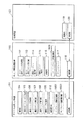
Claims (6)
前記取得した画像をメモリに記憶させる記憶制御手段と、
テンプレート画像を記憶する情報処理装置と通信を行う通信手段と、
前記テンプレート画像に対応する縮小画像を記憶するテンプレート画像記憶手段と、
前記縮小画像から合成すべき縮小画像を選択するための選択手段と、
前記取得または記憶された画像に、前記選択された縮小画像を合成した合成画像を表示する表示手段と、
前記合成画像の印刷要求を入力するための入力手段とを有し、
前記通信手段は、前記印刷要求が入力されると、印刷を指示するコマンド、前記取得または記憶された印刷すべき画像、および、前記選択された縮小画像を示すIDを前記情報処理装置へ送信して、前記情報処理装置に、前記印刷すべき画像に前記 ID に対応するテンプレート画像を合成した印刷イメージを生成させることを特徴とする画像入力装置。An acquisition means for acquiring an image;
Storage control means for storing the acquired image in a memory;
Communication means for communicating with an information processing apparatus for storing a template image ;
Template image storage means for storing a reduced image corresponding to the template image;
Selecting means for selecting a reduced image to be synthesized from the reduced image;
Display means for displaying a synthesized image obtained by synthesizing the selected reduced image with the acquired or stored image;
Input means for inputting a print request for the composite image,
Said communication means, when the print request is input, a command for instructing the printing, the acquired or stored to be printed image, and transmits the ID indicating the reduced image the selected to the information processing apparatus Te, to the information processing apparatus, an image input apparatus according to claim Rukoto to produce a printed image obtained by combining the template image corresponding to the ID to the image to be the printing.
前記縮小画像から選択された合成すべき縮小画像の選択指示を入力し、
前記取得または記憶された画像に、前記選択された縮小画像を合成した合成画像を表示し、
前記合成画像の印刷要求を入力し、
前記印刷要求が入力されると、印刷を指示するコマンド、前記取得または記憶された印刷すべき画像、および、前記選択された縮小画像を示すIDを前記通信手段を介して前記情報処理装置へ送信して、前記情報処理装置に、前記印刷すべき画像に前記 ID に対応するテンプレート画像を合成した印刷イメージを生成させることを特徴とする制御方法。Acquisition means for acquiring an image, storage control means for storing the acquired image in a memory, communication means for communicating with an information processing apparatus for storing a template image, and a template image for storing a reduced image corresponding to the template image A control method for an image input device having a storage means ,
Input a selection instruction of a reduced image to be synthesized selected from the reduced images,
Displaying a synthesized image obtained by synthesizing the selected reduced image on the acquired or stored image;
Input a print request for the composite image,
When the print request is input , a command instructing printing, the acquired or stored image to be printed, and an ID indicating the selected reduced image are transmitted to the information processing apparatus via the communication unit. to, to the information processing apparatus, a control method according to claim Rukoto to produce a printed image obtained by combining the template image corresponding to the ID to the image to be the printing.
Priority Applications (2)
| Application Number | Priority Date | Filing Date | Title |
|---|---|---|---|
| JP18688099A JP4046897B2 (en) | 1999-06-30 | 1999-06-30 | Image input apparatus and control method thereof |
| US09/598,767 US6867882B1 (en) | 1999-06-30 | 2000-06-22 | Image inputting apparatus and its control method, information processing apparatus and method, and print system |
Applications Claiming Priority (1)
| Application Number | Priority Date | Filing Date | Title |
|---|---|---|---|
| JP18688099A JP4046897B2 (en) | 1999-06-30 | 1999-06-30 | Image input apparatus and control method thereof |
Related Child Applications (1)
| Application Number | Title | Priority Date | Filing Date |
|---|---|---|---|
| JP2007133410A Division JP4509139B2 (en) | 2007-05-18 | 2007-05-18 | Image input device and control method thereof, information processing device and method thereof, and printing system |
Publications (3)
| Publication Number | Publication Date |
|---|---|
| JP2001016539A JP2001016539A (en) | 2001-01-19 |
| JP2001016539A5 JP2001016539A5 (en) | 2005-04-28 |
| JP4046897B2 true JP4046897B2 (en) | 2008-02-13 |
Family
ID=16196307
Family Applications (1)
| Application Number | Title | Priority Date | Filing Date |
|---|---|---|---|
| JP18688099A Expired - Lifetime JP4046897B2 (en) | 1999-06-30 | 1999-06-30 | Image input apparatus and control method thereof |
Country Status (2)
| Country | Link |
|---|---|
| US (1) | US6867882B1 (en) |
| JP (1) | JP4046897B2 (en) |
Families Citing this family (36)
| Publication number | Priority date | Publication date | Assignee | Title |
|---|---|---|---|---|
| US6786420B1 (en) | 1997-07-15 | 2004-09-07 | Silverbrook Research Pty. Ltd. | Data distribution mechanism in the form of ink dots on cards |
| US6618117B2 (en) | 1997-07-12 | 2003-09-09 | Silverbrook Research Pty Ltd | Image sensing apparatus including a microcontroller |
| US7551201B2 (en) | 1997-07-15 | 2009-06-23 | Silverbrook Research Pty Ltd | Image capture and processing device for a print on demand digital camera system |
| US6690419B1 (en) | 1997-07-15 | 2004-02-10 | Silverbrook Research Pty Ltd | Utilising eye detection methods for image processing in a digital image camera |
| US7110024B1 (en) | 1997-07-15 | 2006-09-19 | Silverbrook Research Pty Ltd | Digital camera system having motion deblurring means |
| US6624848B1 (en) | 1997-07-15 | 2003-09-23 | Silverbrook Research Pty Ltd | Cascading image modification using multiple digital cameras incorporating image processing |
| US6879341B1 (en) | 1997-07-15 | 2005-04-12 | Silverbrook Research Pty Ltd | Digital camera system containing a VLIW vector processor |
| AUPP702098A0 (en) | 1998-11-09 | 1998-12-03 | Silverbrook Research Pty Ltd | Image creation method and apparatus (ART73) |
| AUPQ056099A0 (en) | 1999-05-25 | 1999-06-17 | Silverbrook Research Pty Ltd | A method and apparatus (pprint01) |
| WO2001083222A1 (en) * | 2000-04-28 | 2001-11-08 | Seiko Epson Corporation | Printing device and printing method |
| JP2002165159A (en) * | 2000-11-24 | 2002-06-07 | Konica Corp | Printing system, photographing apparatus, print reception processing apparatus, print management apparatus, print processing apparatus, storage medium, print servicing method, print reception processing method, print management method, and print processing method |
| AUPR256301A0 (en) * | 2001-01-17 | 2001-02-08 | Silverbrook Research Pty. Ltd. | An apparatus (AP15) |
| JP4182464B2 (en) | 2001-02-09 | 2008-11-19 | 富士フイルム株式会社 | Video conferencing system |
| US20030053116A1 (en) | 2001-09-19 | 2003-03-20 | Fumiharu Nakayama | Image forming apparatus and method of controlling the apparatus |
| US20040076342A1 (en) * | 2001-12-20 | 2004-04-22 | Ricoh Company, Ltd. | Automatic image placement and linking |
| EP2302507A1 (en) | 2002-03-01 | 2011-03-30 | Seiko Epson Corporation | Image output system including a plurality of units connected by communication with master-slave relation |
| JP4307015B2 (en) * | 2002-06-04 | 2009-08-05 | キヤノン株式会社 | Printing apparatus and control method thereof |
| JP3809403B2 (en) * | 2002-07-16 | 2006-08-16 | キヤノン株式会社 | Imaging device, external processing device, control program for imaging device, control program for external processing device |
| JP4233293B2 (en) * | 2002-09-20 | 2009-03-04 | 株式会社リコー | Image forming apparatus and image forming method |
| US20040057078A1 (en) * | 2002-09-20 | 2004-03-25 | Coffin Roderick Franklin | Method and system for printing |
| JP4217458B2 (en) * | 2002-10-28 | 2009-02-04 | キヤノン株式会社 | Printing system, external operation device, information processing device, data processing method, storage medium |
| JP4193466B2 (en) * | 2002-11-05 | 2008-12-10 | 富士フイルム株式会社 | Image transmission / reception system, image transmission apparatus, and image reception apparatus |
| JP4085786B2 (en) * | 2002-11-12 | 2008-05-14 | セイコーエプソン株式会社 | Digital camera, printing system, and computer-readable recording medium |
| JP4250442B2 (en) * | 2003-03-25 | 2009-04-08 | キヤノン株式会社 | Information processing apparatus, information input apparatus, information processing apparatus control method, information input apparatus control method, program, and computer-readable recording medium |
| JP4136771B2 (en) | 2003-04-23 | 2008-08-20 | キヤノン株式会社 | COMMUNICATION SYSTEM, COMMUNICATION DEVICE, ITS CONTROL METHOD, AND COMPUTER PROGRAM |
| JP4125172B2 (en) | 2003-04-23 | 2008-07-30 | キヤノン株式会社 | Wireless communication system, wireless communication apparatus, control method therefor, and computer program |
| JP4125173B2 (en) | 2003-04-23 | 2008-07-30 | キヤノン株式会社 | Information processing apparatus connection control method, information processing apparatus, and computer program |
| JP2004334531A (en) * | 2003-05-07 | 2004-11-25 | Olympus Corp | Control system, control method, print system, image data controller, and program |
| JP4886463B2 (en) | 2006-10-20 | 2012-02-29 | キヤノン株式会社 | Communication parameter setting method, communication apparatus, and management apparatus for managing communication parameters |
| US20120039537A1 (en) * | 2010-08-10 | 2012-02-16 | Keys Gregory C | Method, apparatus, and system for workflow participation of an imaging device |
| JP5922013B2 (en) | 2011-12-28 | 2016-05-24 | 富士フイルム株式会社 | Optical member set and solid-state imaging device using the same |
| JP5976523B2 (en) | 2011-12-28 | 2016-08-23 | 富士フイルム株式会社 | Optical member set and solid-state imaging device using the same |
| WO2014104137A1 (en) | 2012-12-28 | 2014-07-03 | 富士フイルム株式会社 | Curable resin composition, infrared cut-off filter, and solid-state imaging element using same |
| JP6140604B2 (en) | 2012-12-28 | 2017-05-31 | 富士フイルム株式会社 | Curable resin composition for forming infrared reflection film, infrared reflection film and method for producing the same, infrared cut filter, and solid-state imaging device using the same |
| US10423564B2 (en) * | 2013-07-03 | 2019-09-24 | Hewlett-Packard Development Company, L.P. | Universal serial bus data routing |
| JP6304114B2 (en) * | 2015-04-21 | 2018-04-04 | 京セラドキュメントソリューションズ株式会社 | Information processing system |
Family Cites Families (8)
| Publication number | Priority date | Publication date | Assignee | Title |
|---|---|---|---|---|
| US5477264A (en) * | 1994-03-29 | 1995-12-19 | Eastman Kodak Company | Electronic imaging system using a removable software-enhanced storage device |
| JP3037140B2 (en) * | 1996-06-13 | 2000-04-24 | 日本電気オフィスシステム株式会社 | Digital camera |
| US6115137A (en) * | 1996-12-06 | 2000-09-05 | Canon Kabushiki Kaisha | Image processing system, digital camera, and printing apparatus |
| JP3690024B2 (en) * | 1996-12-25 | 2005-08-31 | カシオ計算機株式会社 | Printing apparatus and captured image printing method using printing apparatus |
| JPH10334212A (en) * | 1997-04-01 | 1998-12-18 | Fuji Photo Film Co Ltd | System for printing image from image file with additional information |
| JP3522495B2 (en) * | 1997-06-13 | 2004-04-26 | 三洋電機株式会社 | Image synthesis method and digital camera |
| JPH1132295A (en) * | 1997-07-09 | 1999-02-02 | Olympus Optical Co Ltd | Digital color printer, digital camera and digital color print system using them |
| JPH11127323A (en) * | 1997-10-21 | 1999-05-11 | Canon Inc | Image memory device, digital camera, image processing system, data processing method for image processing system, and storage medium storing computer-readable program |
-
1999
- 1999-06-30 JP JP18688099A patent/JP4046897B2/en not_active Expired - Lifetime
-
2000
- 2000-06-22 US US09/598,767 patent/US6867882B1/en not_active Expired - Lifetime
Also Published As
| Publication number | Publication date |
|---|---|
| US6867882B1 (en) | 2005-03-15 |
| JP2001016539A (en) | 2001-01-19 |
Similar Documents
| Publication | Publication Date | Title |
|---|---|---|
| JP4046897B2 (en) | Image input apparatus and control method thereof | |
| US9405768B2 (en) | Creation of image designating file and reproduction of image using same | |
| US7812859B2 (en) | Print system and print control method | |
| US7365754B2 (en) | System and method for applying color management on captured images | |
| JP5212434B2 (en) | Image holding apparatus and image reproduction system | |
| US7698471B2 (en) | Print system, information processing device and control method for the same, printer and control method for the same, storage medium, and program | |
| US20060017955A1 (en) | Selective graphic instance rendering | |
| JP2002111995A (en) | Image editing device and method and image print control device and method | |
| JP3077581B2 (en) | Color printing equipment | |
| JP2006134317A (en) | Printing method using ordering file, print system, image supply device and print device employing same method | |
| US7190473B1 (en) | Printer apparatus with integrated graphical user interface and method for using the same | |
| JP4343057B2 (en) | Image forming system | |
| JP4509139B2 (en) | Image input device and control method thereof, information processing device and method thereof, and printing system | |
| JP2002137456A (en) | Imaging system, imaging apparatus and imaging program | |
| JP4508953B2 (en) | Image processing method and image processing apparatus | |
| JP3840141B2 (en) | Image processing apparatus, information input apparatus, and methods thereof | |
| JP4717543B2 (en) | Image editing apparatus, control method therefor, program, and storage medium | |
| JP2002118765A (en) | Image processing system and its control method | |
| JP2003046917A (en) | Print system, imaging apparatus, imaging image-printing method, and program | |
| JP2023021793A (en) | Image processing system, terminal device, server device, control method thereof, program, and storage medium | |
| JP2001197406A (en) | Image processing unit, printer, image processing system, print system, image processing method, and storage medium | |
| JP2000013719A (en) | Printer | |
| KR100657272B1 (en) | Method and apparatus for image printing in printer | |
| JPH0876946A (en) | Printer device | |
| JP2008244995A (en) | Image processing system |
Legal Events
| Date | Code | Title | Description |
|---|---|---|---|
| A521 | Request for written amendment filed |
Free format text: JAPANESE INTERMEDIATE CODE: A523 Effective date: 20040617 |
|
| A621 | Written request for application examination |
Free format text: JAPANESE INTERMEDIATE CODE: A621 Effective date: 20040617 |
|
| RD01 | Notification of change of attorney |
Free format text: JAPANESE INTERMEDIATE CODE: A7426 Effective date: 20040617 |
|
| RD03 | Notification of appointment of power of attorney |
Free format text: JAPANESE INTERMEDIATE CODE: A7423 Effective date: 20040617 |
|
| A977 | Report on retrieval |
Free format text: JAPANESE INTERMEDIATE CODE: A971007 Effective date: 20070308 |
|
| A131 | Notification of reasons for refusal |
Free format text: JAPANESE INTERMEDIATE CODE: A131 Effective date: 20070319 |
|
| A521 | Request for written amendment filed |
Free format text: JAPANESE INTERMEDIATE CODE: A523 Effective date: 20070518 |
|
| A131 | Notification of reasons for refusal |
Free format text: JAPANESE INTERMEDIATE CODE: A131 Effective date: 20070622 |
|
| A521 | Request for written amendment filed |
Free format text: JAPANESE INTERMEDIATE CODE: A523 Effective date: 20070808 |
|
| TRDD | Decision of grant or rejection written | ||
| A01 | Written decision to grant a patent or to grant a registration (utility model) |
Free format text: JAPANESE INTERMEDIATE CODE: A01 Effective date: 20071102 |
|
| A61 | First payment of annual fees (during grant procedure) |
Free format text: JAPANESE INTERMEDIATE CODE: A61 Effective date: 20071121 |
|
| FPAY | Renewal fee payment (event date is renewal date of database) |
Free format text: PAYMENT UNTIL: 20101130 Year of fee payment: 3 |
|
| R150 | Certificate of patent or registration of utility model |
Free format text: JAPANESE INTERMEDIATE CODE: R150 Ref document number: 4046897 Country of ref document: JP Free format text: JAPANESE INTERMEDIATE CODE: R150 |
|
| FPAY | Renewal fee payment (event date is renewal date of database) |
Free format text: PAYMENT UNTIL: 20101130 Year of fee payment: 3 |
|
| FPAY | Renewal fee payment (event date is renewal date of database) |
Free format text: PAYMENT UNTIL: 20111130 Year of fee payment: 4 |
|
| FPAY | Renewal fee payment (event date is renewal date of database) |
Free format text: PAYMENT UNTIL: 20121130 Year of fee payment: 5 |
|
| FPAY | Renewal fee payment (event date is renewal date of database) |
Free format text: PAYMENT UNTIL: 20131130 Year of fee payment: 6 |
|
| EXPY | Cancellation because of completion of term |