JP4010975B2 - Mobile communication terminal device - Google Patents
Mobile communication terminal device Download PDFInfo
- Publication number
- JP4010975B2 JP4010975B2 JP2003103319A JP2003103319A JP4010975B2 JP 4010975 B2 JP4010975 B2 JP 4010975B2 JP 2003103319 A JP2003103319 A JP 2003103319A JP 2003103319 A JP2003103319 A JP 2003103319A JP 4010975 B2 JP4010975 B2 JP 4010975B2
- Authority
- JP
- Japan
- Prior art keywords
- imaging
- unit
- communication terminal
- mobile communication
- terminal device
- Prior art date
- Legal status (The legal status is an assumption and is not a legal conclusion. Google has not performed a legal analysis and makes no representation as to the accuracy of the status listed.)
- Expired - Fee Related
Links
Images


Classifications
-
- H—ELECTRICITY
- H04—ELECTRIC COMMUNICATION TECHNIQUE
- H04B—TRANSMISSION
- H04B1/00—Details of transmission systems, not covered by a single one of groups H04B3/00 - H04B13/00; Details of transmission systems not characterised by the medium used for transmission
- H04B1/38—Transceivers, i.e. devices in which transmitter and receiver form a structural unit and in which at least one part is used for functions of transmitting and receiving
- H04B1/40—Circuits
-
- H—ELECTRICITY
- H04—ELECTRIC COMMUNICATION TECHNIQUE
- H04M—TELEPHONIC COMMUNICATION
- H04M1/00—Substation equipment, e.g. for use by subscribers
- H04M1/02—Constructional features of telephone sets
- H04M1/0202—Portable telephone sets, e.g. cordless phones, mobile phones or bar type handsets
- H04M1/0206—Portable telephones comprising a plurality of mechanically joined movable body parts, e.g. hinged housings
- H04M1/0208—Portable telephones comprising a plurality of mechanically joined movable body parts, e.g. hinged housings characterized by the relative motions of the body parts
- H04M1/0225—Rotatable telephones, i.e. the body parts pivoting to an open position around an axis perpendicular to the plane they define in closed position
-
- H—ELECTRICITY
- H04—ELECTRIC COMMUNICATION TECHNIQUE
- H04M—TELEPHONIC COMMUNICATION
- H04M1/00—Substation equipment, e.g. for use by subscribers
- H04M1/02—Constructional features of telephone sets
- H04M1/0202—Portable telephone sets, e.g. cordless phones, mobile phones or bar type handsets
- H04M1/0206—Portable telephones comprising a plurality of mechanically joined movable body parts, e.g. hinged housings
- H04M1/0241—Portable telephones comprising a plurality of mechanically joined movable body parts, e.g. hinged housings using relative motion of the body parts to change the operational status of the telephone set, e.g. switching on/off, answering incoming call
- H04M1/0245—Portable telephones comprising a plurality of mechanically joined movable body parts, e.g. hinged housings using relative motion of the body parts to change the operational status of the telephone set, e.g. switching on/off, answering incoming call using open/close detection
-
- H—ELECTRICITY
- H04—ELECTRIC COMMUNICATION TECHNIQUE
- H04N—PICTORIAL COMMUNICATION, e.g. TELEVISION
- H04N7/00—Television systems
- H04N7/14—Systems for two-way working
- H04N7/141—Systems for two-way working between two video terminals, e.g. videophone
- H04N7/142—Constructional details of the terminal equipment, e.g. arrangements of the camera and the display
-
- H—ELECTRICITY
- H04—ELECTRIC COMMUNICATION TECHNIQUE
- H04M—TELEPHONIC COMMUNICATION
- H04M2250/00—Details of telephonic subscriber devices
- H04M2250/52—Details of telephonic subscriber devices including functional features of a camera
-
- H—ELECTRICITY
- H04—ELECTRIC COMMUNICATION TECHNIQUE
- H04N—PICTORIAL COMMUNICATION, e.g. TELEVISION
- H04N7/00—Television systems
- H04N7/14—Systems for two-way working
- H04N7/141—Systems for two-way working between two video terminals, e.g. videophone
- H04N7/142—Constructional details of the terminal equipment, e.g. arrangements of the camera and the display
- H04N2007/145—Handheld terminals
Description
【0001】
【発明の属する技術分野】
本発明は、携帯通信端末装置(以下、単に携帯通信端末ともいう)に係り、特に、デジタルカメラ機能(撮像機能)を備え、下側筐体に対して上側筐体がスライド回転する折り畳み型の携帯通信端末装置に関する。
【0002】
【従来の技術】
従来、携帯電話機のような携帯通信端末であって撮像機能を備えたものが、特許文献1等に知られている。この携帯通信端末は電話利用時に利用されるLCD(液晶表示部)を撮像時にもファインダとして利用し、撮像に際して被写体の画像をリアルタイムでLCDに写して写り具合を確認した後、撮像を行うことができるようになっている。LCDは折り畳み式の上側筐体の内側の主面に配置されているので、撮像時にLCDをファインダとして利用する場合には下側筐体に対して上側筐体を開いた状態で撮像が行われる。
【0003】
また、最近の市場に出回っている携帯電話機においても、表示画面サイズを大きくし、かつ収納サイズを小さくできる等の理由から折り畳み型の機種が主流となってきており、上側筐体の閉状態でも電波状態や日時、着信情報等が視覚的に認識できるように上側筐体の外表面にサブ表示部を設けているのが一般的である。このような折り畳み型の携帯電話機であってデジタルカメラ機能を備えたものでは、やはり上側筐体を開いた状態でのユーザのキー操作によりカメラモードに移行し、メイン表示部をファインダとして利用しながら撮像が行えるようになっている。
【0004】
【特許文献1】
特開平10−336498号公報
【0005】
【発明が解決しようとする課題】
上記従来の折り畳み型の携帯通信端末の開閉動作はいずれも、二枚貝の開閉動作に類したものであり、上側筐体の下端の辺(下側筐体の上側の辺)に平行な軸を回転軸として開閉するものである。この構造上、通信時に利用されるメイン表示部と、テンキーや通話キーおよび終話キー等を含む操作部とはそれぞれ上側筐体および下側筐体の内側の主面上に配置され、筐体の閉鎖時には表示部と操作部とが対向する形で内側に隠れてしまう。このような構造上の理由から、メイン表示部を撮像時のファインダとして利用するには、上側筐体を開放した状態で用いる必要がある。これは、一般的なカメラの形態や取り扱いとは異なり、ユーザにとって違和感があるとともにその操作性も劣る。
【0006】
また、従来の折り畳み型の携帯通信端末で撮像を行う際、その前提として、まず筐体を開き、次にカメラモードキーを押下してカメラモードへ移行し、その後、シャッタボタンに指を移して撮像動作に入る、という手間が必要であり、迅速な撮像を行うという点でも操作性に問題があった。
【0007】
なお、上記特許文献1に記載の携帯通信端末では上側筐体を閉じた状態での撮像も可能であるが、この場合にはLCDを撮像時のファインダとして利用することができず、別途、専用のファインダを設けて、これを利用するようにしている。このように別途専用のファインダを設けることは装置のコスト増の原因となる。
【0008】
本発明はこのような背景においてなされたものであり、その目的は、専用のファインダやサブ表示部を設ける必要なく、通信時に利用される表示部を撮像時のファインダとしても利用可能であり、カメラとしての使用時に一般的なカメラと同様の形態で取り扱うことができる操作性の良好な携帯通信端末装置を提供することにある。
【0009】
【課題を解決するための手段】
上記目的を達成するために、本発明は、上記のような二枚貝的な開閉ではなく、本願出願人が先に特願2002−063635号において提案したような型(回転スライド型またはジャックナイフ型)の折り畳み開閉を行う携帯通信端末装置にデジタルカメラ機能を付与したものである。
【0010】
すなわち、本発明による携帯通信端末装置は、撮像機能を有する携帯通信端末装置であって、主面において各種キーを有する操作部を配置した下側筐体と、主面において表示画面を有する表示部を配置した上側筐体と、前記上側筐体の端部において前記表示画面にほぼ垂直な軸を回転軸としてスライド回転可能に結合し、前記上側筐体の表示部を露出すると共に前記下側筐体の操作部が前記上側筐体によって遮蔽される閉状態と、前記上側筐体の表示部および前記下側筐体の操作部が露出する開状態とを前記スライド回転によって変更する結合部と、前記下側筐体の前記操作部の裏面に配置され、前記閉状態においても露出する位置に設けられた撮像部と、前記表示部の表示画面をファインダとして利用し前記撮像部の撮像動作を制御する撮像制御手段と、前記閉状態および開状態を検出する開閉検出手段をさらに備え、前記撮像制御手段は、撮像モードへの移行の指示を受けた場合、前記上側筐体が前記開状態にあると判断されたとき、撮像モードへの移行または前記撮像部による撮像動作を抑止することを特徴とする。
【0011】
上側筐体と下側筐体とはその結合部において表示画面にほぼ垂直な軸を回転軸としてスライド回転するものである。このようなスライド回転折り畳み型の場合、筐体が開かれているか閉じられているかを問わず、表示部の表示画面は常に外側に露出されており、筐体の閉状態においてもユーザが表示画面全体を視認可能となる。したがって、従来のように閉状態での表示情報認識のために別途サブ表示部を設ける必要がなくなる。また、閉状態のまま撮像時のファインダとして表示部を利用することができる。
【0012】
好ましくは、前記撮像制御手段は、前記撮像ボタンの所定の操作に従って撮像モードに移行し、この撮像モードでは、前記表示部の表示画面をファインダとして利用し前記撮像ボタンの操作に応じて前記撮像部による撮像を行う。本発明の携帯通信端末では撮像時に筐体を開く必要がないので、撮像モードへの移行に、外側面に設けられている撮像ボタンを利用することにより、迅速に撮像モードへの移行が行え、かつ、そのままの体勢で撮像動作に移ることができる。
【0013】
前記閉状態および開状態を検出する開閉検出手段をさらに備え、前記撮像制御手段は、撮像モードへの移行の指示をうけた場合、前記上側筐体が前記開状態にあると判断されたとき、撮像モードへの移行または前記撮像部による撮像動作を抑止するようにしてもよい。あるいは、前記撮像制御手段は、撮像モードに入っている状態で前記上側筐体が開状態になったと判断されたとき、前記撮像部による撮像動作を抑止する。これらの抑止動作は、筐体を閉じた一般的なカメラ形態での撮像動作を保証するよう機能する。
【0014】
【発明の実施の形態】
以下、本発明の実施の形態について、図面を参照して詳細に説明する。
【0015】
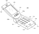
図1に、本実施の形態に係る回転スライド折り畳み型の携帯通信端末装置の折り畳んだ状態(閉状態)の第1の斜視図を示し、図2に別の視点からの第2の斜視図を示す。
【0016】
図示の携帯通信端末130は、第1の筐体である下側筐体111と第2の筐体である上側筐体(上蓋)112とを備える。上側筐体112は、その内側の主面に、例えばLCDのような平面表示デバイスからなる表示部123を有する。上側筐体112は、その端部において、表示部123の表示画面にほぼ垂直な軸を回転軸として下側筐体111に対してスライド回転可能に結合されている。下側筐体111は、その内側の主面に、各種キーを有する第1の操作部である主操作部(図1、図2では隠れて見えない)を有する。両筐体が折り畳まれて重ね合わされた状態であっても、この折り畳みは二枚貝型ではなく回転スライド型なので、上側筐体112の表示部123は外部に露出している。
【0017】
上側筐体112の表示部123が配置されたと同じ主面上には、副操作部(第2の操作部)としてのジョグダイヤル121および操作ボタン122a,122bが設けられている。ジョグダイヤル121は押しボタンスイッチを兼ねた回転ダイヤル操作手段である。さらに、同主面上の表示部123の近傍にはイヤレシーバ124が配置されている。
【0018】
下側筐体111の外側面には、撮像を指示する撮像ボタンとしてのシャッタボタン25が配置されている。図1に示した状態の携帯通信端末130において、ジョグダイヤル121をユーザの右手側手前に向けた横長の状態で(表示部123の画面も手前に向く)、少なくとも右手で装置の右側部分を把持したとき、シャッタボタン25は、ほぼ、右手の人差し指の先端腹部の下に当たる付近に位置する構成となっている。
【0019】
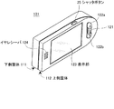
一方、図2からわかるように、下側筐体111の外側主面には、電池カバー340が配置され、その横に、撮像部のレンズ31、ミラー32およびスピーカ33が配置されている。ミラー32は、ユーザがレンズ31を自身に向けて撮像する際のファインダ代わりとするためのものである。但し、レンズ31、ミラー32およびスピーカ33の位置関係やサイズは図示のものに限るものではない。
【0020】
図1、図2に示したような、筐体の閉状態での、表示部123を利用したファインダ画面、およびシャッタボタン25、レンズ31の配置関係によって、この携帯通信端末130は既存のデジタルカメラの形態と実質的に同じ形態を有し、かつ、ユーザは同じ取り扱い方法で撮像を行うことができる。
【0021】
図3は、図1,図2に示した携帯通信端末130の閉状態から、下側筐体111に対して上側筐体112をスライド回転させて開放する途中の状態の外観を示している。図では上側筐体112を下側筐体11に対して時計方向に回転させているが、時計方向および反時計方向のいずれにも回転させうる。
【0022】
図4は、図3の状態を経て、上側筐体112を開放しきった状態の外観を示している。本実施の形態では、図4の状態から、開いたとき同じ回転方向にさらに回転させることはできず、開いたときの逆方向に回転させることにより再度折り畳み状態に戻すことができる。これは、上側筐体と下側筐体の電気的接続を行うケーブル(図示せず)が結合部内を貫通しており、そのよじれ等を防止するためである。ケーブルのよじれ等の問題が生じなければ、図4の状態から、開いたとき同じ回転方向に回転させることも可能である。
【0023】
下側筐体111の内側の主表面には各種キーからなる主操作部116が配置され、マイク114も配置されていることが、図4から分かる。同主表面の周囲の複数箇所に配置された複数の突起118は、両筐体が重ね合わされたときに上側筐体112が誤って主操作部116のキーを押圧しないようにするためのスペーサの役割を果たしている。このような突起118は本発明に必須のものではなく、突起118の代わりに主操作部116のキーの誤押圧を防止できる任意の構造を採用することができる。
【0024】
図4に示した上側筐体112を開いた状態は、音声通話時、電子メールの作成、送信、アドレス帳やメモ帳の編集等、主として、主操作部116を利用する際の利用形態である。
【0025】
このような回転スライド折り畳み型の携帯通信端末130は従来の二枚貝折り畳み型と同様に折り畳み時のサイズを縮小できる利点がある。二枚貝折り畳み型と異なるのは、重ね合わせた状態でも表示部123が外部に露出していることである。したがって、上述したカメラ機能に関して専用のファインダを設ける必要がないだけでなく、サブ表示部を設ける必要もない。その結果、折り畳み状態で表示部123により電子メールの着信内容の確認を行う等、表示部123の利用価値が向上する。
【0026】
図5は、図1に示した携帯通信端末130のシャッタボタン25の位置を、下側筐体111から上側筐体112側へ移動させた構成を有する他の携帯通信端末131の外観を示している。携帯通信端末131の内部構成は携帯通信端末130と同じである。筐体の閉状態で撮像機能を利用する限りは、操作性において両者に変わりはない。ただし、シャッタボタン25を、筐体の開状態で撮像機能以外の用途に利用する場合には下側筐体111に設ける方が好ましい。また、シャッタボタン25としての電気的スイッチの配線の長さの観点からも、電池のある下側筐体111にシャッタボタン25を設ける方が好ましいと言える。
【0027】
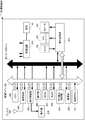
図6に、本実施の形態の携帯通信端末130のハードウェア構成を示す。
【0028】
携帯通信端末130の全体の動作はCPU220により制御される。CPU220は、制御ライン200を介して、通信回路203、表示制御部209、操作部206、ROM207、RAM208、折り畳み検知部218、撮像部219、撮像ボタン231(図1の25に対応)および音声処理部215と接続され、これらの各部を制御する。
【0029】
通信回路203は、携帯通信端末の送受信処理を行う部位であり、アンテナ202により無線インタフェースを介して基地局と接続される。表示制御部209は表示部210(図1の表示部123に対応)の表示制御を行う部位である。操作部206(図1の主操作部116に対応)は、ユーザの入力指示を受け付ける部位である。ROM207は、CPU220により実行される固定的なプログラムおよびこれに付随した固定的なデータ(フォントデータ等)を記憶するメモリである。RAM208はCPU220の利用に供されるデータの一時保存領域や作業領域を提供するメモリである。折り畳み検知部218は下側筐体に対する上側筐体の開閉状態を検知するための既知の手段である。撮像部219は、撮像処理を行う部位であり、上記レンズ31の他、CCD等の撮像素子およびその制御回路を有する。音声処理部215は、マイク232(図1の114に対応)、イヤレシーバ233(図1の120に対応)、およびスピーカ234(図2の33に対応)に接続され、音声の入出力処理を行う部位である。
【0030】
データライン201は、CPU220、通信回路203、表示制御部209、ROM207、RAM208、音声処理部215、撮像部219と接続され、これらの任意の部位間のデータの転送路を提供する。
【0031】
通常、充電可能な電池45は下側筐体111内に交換可能に装着され、この電池45に接続されて装置各部に所定の動作電力を供給する電源回路213が設けられている。
【0032】
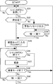
図7に、本実施の形態における携帯通信端末の撮像に関する第1の動作例のフローチャートを示す。この処理はCPU220によりROM207等に格納されたコンピュータプログラムの実行処理により実現される。
【0033】
本実施の形態では、ユーザによる撮像モード(カメラモード)への移行の指示として、シャッタボタン25の所定の操作(例えば、所定時間以上連続した押下、すなわち長押し)を採用する。シャッタボタン25は筐体の折り畳み状態(閉状態)で外部に露出しており、かつ、非撮像モード時にはシャッタボタン25の押下によって誤撮像はあり得ないからである。勿論、ジョグダイヤル121等の第2の操作部も筐体の折り畳み状態で外部に露出しており、ジョグダイヤルによるメニュー操作、あるいは操作ボタン122a,122bのいずれかの操作を利用することも可能である。ただし、簡便さおよび操作の分かりやすさからは、撮像モードへの移行の指示にはシャッタボタン25の利用が好適と考えられる。
【0034】
シャッタボタン25の長押し等により、ユーザによる撮像モードへの移行の指示があったとき、CPUは筐体が閉状態であるか否かをチェックする(S12)。閉状態であれば、撮像モードに入る(S15)。このとき、表示部123を撮像用のファインダとして利用開始する。これにより、レンズを通して得られた撮像対象の被写体の像がほぼリアルタイムに表示部123の画面上に表示される。閉状態でなければ(すなわち開状態であれば)、例えば「上蓋を閉じてください」のような、上側筐体の閉鎖を促す警告メッセージを表示画面上に表示出力する(S13)。これに代えて、または併せて、所定の警告音や音声メッセージ等をスピーカおよび/またはイヤレシーバから発するようにしてもよい。警告メッセージ出力の後、上側筐体が閉じられるのを待って(S14)、撮像モードに入る(S15)。
【0035】
撮像モードに入った後、シャッタボタンが押下されたら(S16)、撮像動作を実行する(S17)。撮像モード終了の指示があれば(S18,No)、最初のステップS11へ戻る。ここでの撮像モード終了の指示とは、筐体の折り畳み状態のまま、ユーザが第2の操作部の例えばジョグダイヤルの操作により行うものである。撮像モード終了の指示がある前に、上側筐体が開放されたら(S19,Yes)、撮像を抑止する(S20)。この撮像の抑止とは、少なくとも、シャッタボタンの押下の無効化である。これに加えて、表示部のファインダとしてのモニタ機能をオフとしてもよい。この後、上記ステップS13と同様の警告メッセージを出力する(S21)。
【0036】
本実施の形態において筐体の開状態での撮像を抑止する理由は次のとおりである。
(1)回転スライド型であるために筐体の開状態での撮像を許可すると、閉状態と開状態とで表示部と撮像部との相互の上下関係が逆になるため、筐体が開閉される毎に表示部のファインダ表示画像を上下逆転させるという余分な処理が必要となること。
(2)開状態での撮像は従来のカメラの使用形態と異なり、操作性が劣化すること。
(3)通常、携帯電話機の終話キー(操作部206の1キー)は任意のユーザ操作を終了する機能が割り当てられており、開状態では操作部が露出するため誤って終話キーを押して撮像モードを予期しない時点で中断してしまうおそれがあること。
(4)閉状態で表示部をファインダとして利用しながら撮像動作を行うことができるので、開状態での撮像が必要となる特段の理由がないこと。
【0037】
ステップS21の後、撮像モード終了の指示があれば、最初のステップS11へ戻る。この撮像モード終了の指示は、主操作部に設けられたキー(例えば終話キー)の押下による。この代わりに、第2の操作部の操作を利用することも可能である。撮像モード終了の指示がなく、上側筐体112が再度閉じられた場合、ステップS15に戻り、撮像モードに復帰する。
【0038】
図8は、本実施の形態における携帯通信端末の撮像に関する第2の動作例のフローチャートを示す。この動作例は、図7に示した第1の動作例と類似しており、ステップS31〜S39は図7のステップS11〜S19と同じである。違いは第2の動作例では第1の動作例のステップS20〜S23を省略したことである。この相違点は、第2の動作例では撮像モードに入った後、筐体を開くと、撮像モードが終了することである。したがって、第2の動作例では、撮像モードに戻るには筐体を閉じて再度シャッタボタンの長押しを行う必要がある。
【0039】
第1の動作例と第2の動作例とを比較すると、第1の動作例では筐体を開いて撮像モードを中断した後、筐体を閉じるだけで即座に撮像モードに戻れるという利点がある。一方、第2の動作例では、撮像モードから離脱したいときに、第1または第2の操作部の操作を行うことなく、筐体を開くだけでその目的を達成できるという利点がある。
【0040】
以上、本発明の好適な実施の形態について説明したが、種々の変形、変更が可能である。例えば、図7,図8の動作例では、撮像モードへの移行の指示を受けた際に、撮像モードに入ること自体を抑止するようにしたが、一旦撮像モードに入って表示部のファインダとしてのモニタ機能をオンにし、シャッタボタン押下時に開状態が確認された場合に撮像動作を抑止するような変形例も考えられる。また、撮像は、静止画だけでなく動画を対象としてもよい。シャッタボタンの位置は図示の位置に限定されるものではない。
【0041】
【発明の効果】
本発明によれば、スライド回転折り畳み型の携帯通信端末に撮像機能を組み合わせることにより、通信時に利用される表示部を撮像時のファインダとしても利用可能となるので、カメラとしての使用時に一般的なカメラと同様の形態で取り扱うことを可能となり、その操作性の向上を図ることができる。また、これにより、専用のファインダやサブ表示部を設ける必要がなくなり、装置コストを低減することが可能となる。
【0042】
上側筐体が閉じられた状態で撮像ボタンの操作により撮像モードへ移行するようにすれば、筐体を閉じたまま迅速に撮像モードに入り、直ちに撮像動作に移行することができる。この間、ユーザは従来のように撮像モードへの移行のために筐体を開いて撮像ボタン以外の別のキーの操作を行ったり、筐体を持ち直したりする手間が不要となる。
【0043】
また、開状態での撮像動作を抑止するようにすれば、不必要な画像処理を行うことなく、かつ、誤動作を防止し、カメラとしての一般的な利用形態および操作性を保証することができる。
【図面の簡単な説明】
【図1】本発明の実施の形態に係る回転スライド型の携帯通信端末の折り畳んだ状態(閉状態)の第1の斜視図である。
【図2】図1に示した携帯通信端末を別の視点から見た第2の斜視図である。
【図3】図1に示した携帯通信端末の下側筐体に対して上側筐体をスライド回転させて開放する途中の状態を示す外観図である。
【図4】図3の状態を経て、上側筐体を開放しきった状態を示す外観図である。
【図5】図1に示した携帯通信端末のシャッタボタンの位置を、下側筐体から上側筐体側へ移動させた構成を有する他の携帯通信端末の外観図である。
【図6】本発明の実施の形態の携帯通信端末のハードウェア構成を示すブロック図である。
【図7】本発明の実施の形態における携帯通信端末の撮像に関する第1の動作例を表すフローチャートである。
【図8】本発明の実施の形態における携帯通信端末の撮像に関する第2の動作例を表すフローチャートである。
【符号の説明】
25…シャッタボタン、111…下側筐体、112…上側筐体、114…マイク、116…主操作部(第1の操作部)、118…突起、121…ジョグダイヤル、122a,122b…操作ボタン、123…表示部、124…イヤレシーバ、130,131…携帯通信端末装置[0001]
BACKGROUND OF THE INVENTION
The present invention relates to a mobile communication terminal device (hereinafter, also simply referred to as a mobile communication terminal), and in particular, a folding type that has a digital camera function (imaging function) and in which an upper housing slides and rotates with respect to a lower housing. The present invention relates to a mobile communication terminal device.
[0002]
[Prior art]
Conventionally, a portable communication terminal such as a mobile phone and having an imaging function is known in Patent Document 1 and the like. This mobile communication terminal uses an LCD (liquid crystal display unit) used when using a telephone as a finder also when taking an image, and after taking an image of the subject on the LCD in real time during imaging, the image is taken and then taken. It can be done. Since the LCD is arranged on the inner main surface of the foldable upper casing, when the LCD is used as a finder during imaging, imaging is performed with the upper casing open relative to the lower casing. .
[0003]
Also, in the mobile phones that are on the market recently, folding type models have become mainstream because the display screen size can be increased and the storage size can be reduced. In general, a sub display unit is provided on the outer surface of the upper casing so that the radio wave status, date and time, incoming call information, and the like can be visually recognized. In such a foldable mobile phone having a digital camera function, the user moves to the camera mode by the user's key operation with the upper casing opened, and the main display unit is used as a finder. Imaging can be performed.
[0004]
[Patent Document 1]
Japanese Patent Laid-Open No. 10-336498
[Problems to be solved by the invention]
The open / close operation of the conventional folding mobile communication terminal is similar to the open / close operation of a bivalve shell, and rotates on an axis parallel to the lower edge of the upper casing (the upper edge of the lower casing). It opens and closes as a shaft. Due to this structure, the main display unit used at the time of communication and the operation unit including a numeric keypad, a call key, and an end key are arranged on the main surface inside the upper casing and the lower casing, respectively. When closed, the display unit and the operation unit are hidden inside so as to face each other. For such a structural reason, in order to use the main display unit as a finder at the time of imaging, it is necessary to use the main display unit with the upper housing opened. This is different from a general camera form and handling, and is uncomfortable for the user and inferior in operability.
[0006]
Also, when imaging with a conventional foldable mobile communication terminal, the premise is that the housing is first opened, then the camera mode key is pressed to enter camera mode, and then the finger is moved to the shutter button. There is a problem in operability in that it takes time and effort to enter an imaging operation, and quick imaging is performed.
[0007]
Note that the mobile communication terminal described in Patent Document 1 can also capture an image with the upper casing closed, but in this case, the LCD cannot be used as a finder during imaging, and is separately dedicated. This finder is provided to use this. Providing a separate dedicated finder in this way increases the cost of the apparatus.
[0008]
The present invention has been made in such a background, and an object of the present invention is to provide a display unit used at the time of communication as a finder at the time of imaging without providing a dedicated finder or a sub display unit. It is an object of the present invention to provide a portable communication terminal device with good operability that can be handled in the same form as a general camera when used as a mobile phone.
[0009]
[Means for Solving the Problems]
In order to achieve the above object, the present invention is not a bivalve open / close as described above, but a type (rotary slide type or jack knife type) previously proposed by the present applicant in Japanese Patent Application No. 2002-063635. A digital camera function is added to a portable communication terminal device that opens and closes.
[0010]
That is, the mobile communication terminal device according to the present invention is a mobile communication terminal device having an imaging function, and includes a lower housing in which an operation unit having various keys is arranged on the main surface, and a display unit having a display screen on the main surface. And an upper housing with an axis that is substantially perpendicular to the display screen at the end of the upper housing so as to be slidably rotatable, exposing the display portion of the upper housing and the lower housing. A coupling unit that changes a closed state in which a body operation unit is shielded by the upper housing and an open state in which the display unit of the upper housing and the operation unit of the lower housing are exposed by the slide rotation; The imaging unit disposed on the back surface of the operation unit of the lower housing and provided at a position exposed even in the closed state and the display screen of the display unit are used as a finder to control the imaging operation of the imaging unit. To take Determining a control means, further comprising an opening and closing detecting means for detecting a closed state and an open state, said imaging control means, and when receiving an instruction to shift to the imaging mode, the upper housing is in the open state When this is done, the shift to the imaging mode or the imaging operation by the imaging unit is suppressed .
[0011]
The upper casing and the lower casing are slidably rotated about the axis that is substantially perpendicular to the display screen at the connecting portion. In such a slide rotation folding type, the display screen of the display unit is always exposed to the outside regardless of whether the casing is open or closed, and the user can display the display screen even when the casing is closed. The whole is visible. Therefore, it is not necessary to provide a separate sub display unit for the display information recognition in the closed state as in the prior art. In addition, the display unit can be used as a finder at the time of imaging in the closed state.
[0012]
Preferably, the imaging control unit shifts to an imaging mode according to a predetermined operation of the imaging button, and in this imaging mode, the imaging unit is used in accordance with an operation of the imaging button by using a display screen of the display unit as a finder. Perform imaging with. In the mobile communication terminal of the present invention, since it is not necessary to open the housing at the time of imaging, the transition to the imaging mode can be performed quickly by using the imaging button provided on the outer surface, And it can move to imaging operation with the same posture.
[0013]
Further comprising an open / close detection means for detecting the closed state and the open state , and when the imaging control means receives an instruction to shift to the imaging mode, when the upper casing is determined to be in the open state, The transition to the imaging mode or the imaging operation by the imaging unit may be suppressed. Alternatively, the imaging control unit suppresses the imaging operation by the imaging unit when it is determined that the upper casing is in an open state in the imaging mode. These suppression operations function to guarantee an imaging operation in a general camera form in which the casing is closed.
[0014]
DETAILED DESCRIPTION OF THE INVENTION
Hereinafter, embodiments of the present invention will be described in detail with reference to the drawings.
[0015]
FIG. 1 shows a first perspective view in a folded state (closed state) of a rotary slide foldable portable communication terminal device according to the present embodiment, and FIG. 2 shows a second perspective view from another viewpoint. Show.
[0016]
The illustrated
[0017]
On the same main surface as the
[0018]
On the outer surface of the
[0019]
On the other hand, as can be seen from FIG. 2, the battery cover 340 is disposed on the outer main surface of the
[0020]
As shown in FIGS. 1 and 2, the
[0021]
FIG. 3 shows the external appearance of the
[0022]
FIG. 4 shows an appearance in a state where the
[0023]
It can be seen from FIG. 4 that a
[0024]
The state in which the
[0025]
Such a rotary slide foldable
[0026]
FIG. 5 shows an appearance of another
[0027]
FIG. 6 shows a hardware configuration of
[0028]
The overall operation of the
[0029]
The
[0030]
The data line 201 is connected to the
[0031]
Usually, the
[0032]
FIG. 7 shows a flowchart of a first operation example relating to imaging of the mobile communication terminal in the present embodiment. This process is realized by the execution process of the computer program stored in the
[0033]
In the present embodiment, a predetermined operation of the shutter button 25 (for example, a continuous press for a predetermined time, that is, a long press) is adopted as an instruction to shift to the imaging mode (camera mode) by the user. This is because the
[0034]
When the user gives an instruction to shift to the imaging mode by long pressing the
[0035]
When the shutter button is pressed after entering the imaging mode (S16), an imaging operation is executed (S17). If there is an instruction to end the imaging mode (S18, No), the process returns to the first step S11. Here, the instruction to end the imaging mode is given by the user operating, for example, the jog dial of the second operation unit while the housing is folded. If the upper housing is opened before an instruction to end the imaging mode is given (S19, Yes), imaging is suppressed (S20). This suppression of imaging is at least invalidation of pressing of the shutter button. In addition to this, the monitor function as a finder of the display unit may be turned off. Thereafter, a warning message similar to that in step S13 is output (S21).
[0036]
In this embodiment, the reason for suppressing the imaging in the open state of the housing is as follows.
(1) Since the rotating and sliding type allows imaging in the open state of the housing, the vertical relationship between the display unit and the imaging unit is reversed between the closed state and the open state, so the housing opens and closes. Every time it is done, an extra process of turning the viewfinder display image of the display unit upside down is required.
(2) The imaging in the open state is different from the conventional usage of the camera, and the operability is deteriorated.
(3) Normally, the end key (1 key of the operation unit 206) of the mobile phone is assigned a function for terminating any user operation, and since the operation unit is exposed in the open state, the end key is accidentally pressed. The imaging mode may be interrupted at an unexpected time.
(4) Since the imaging operation can be performed while using the display unit as a finder in the closed state, there is no particular reason why imaging in the open state is required.
[0037]
If there is an instruction to end the imaging mode after step S21, the process returns to the first step S11. The instruction to end the imaging mode is made by pressing a key (for example, an end key) provided on the main operation unit. Instead of this, it is also possible to use the operation of the second operation unit. If there is no instruction to end the imaging mode and the
[0038]
FIG. 8 shows a flowchart of a second operation example relating to imaging of the mobile communication terminal in the present embodiment. This operation example is similar to the first operation example shown in FIG. 7, and steps S31 to S39 are the same as steps S11 to S19 in FIG. The difference is that in the second operation example, steps S20 to S23 of the first operation example are omitted. The difference is that in the second operation example, when the housing is opened after entering the imaging mode, the imaging mode is terminated. Therefore, in the second operation example, to return to the imaging mode, it is necessary to close the casing and press the shutter button again for a long time.
[0039]
Comparing the first operation example and the second operation example, the first operation example has an advantage that after the housing is opened and the imaging mode is interrupted, the imaging mode can be immediately returned to by simply closing the housing. . On the other hand, the second operation example has an advantage that when the user wants to leave the imaging mode, the object can be achieved simply by opening the housing without operating the first or second operation unit.
[0040]
The preferred embodiment of the present invention has been described above, but various modifications and changes can be made. For example, in the operation examples of FIG. 7 and FIG. 8, when the instruction to shift to the imaging mode is received, entering the imaging mode itself is suppressed, but once entering the imaging mode, the display unit is used as a viewfinder. A modification is also possible in which the monitor function is turned on and the imaging operation is suppressed when the open state is confirmed when the shutter button is pressed. Further, the imaging may be performed not only on still images but also on moving images. The position of the shutter button is not limited to the illustrated position.
[0041]
【The invention's effect】
According to the present invention, by combining an imaging function with a slide rotation folding type portable communication terminal, a display unit used at the time of communication can be used as a finder at the time of imaging. It can be handled in the same form as a camera, and the operability can be improved. In addition, this eliminates the need to provide a dedicated finder or sub-display unit, thereby reducing the apparatus cost.
[0042]
If the camera is shifted to the imaging mode by operating the imaging button with the upper casing closed, the imaging mode can be quickly entered while the casing is closed, and the imaging operation can be immediately started. In the meantime, the user does not need to open the casing for operating in the imaging mode and operate another key other than the imaging button or re-hold the casing as in the prior art.
[0043]
In addition, if the image pickup operation in the open state is suppressed, unnecessary image processing is not performed, a malfunction is prevented, and a general usage form and operability as a camera can be guaranteed. .
[Brief description of the drawings]
FIG. 1 is a first perspective view in a folded state (closed state) of a rotary slide type mobile communication terminal according to an embodiment of the present invention;
FIG. 2 is a second perspective view of the mobile communication terminal shown in FIG. 1 viewed from another viewpoint.
3 is an external view showing a state in the middle of opening the upper casing by sliding and rotating with respect to the lower casing of the mobile communication terminal shown in FIG. 1;
4 is an external view showing a state where the upper housing is fully opened through the state of FIG. 3; FIG.
5 is an external view of another mobile communication terminal having a configuration in which the position of the shutter button of the mobile communication terminal shown in FIG. 1 is moved from the lower housing to the upper housing.
FIG. 6 is a block diagram showing a hardware configuration of the mobile communication terminal according to the embodiment of the present invention.
FIG. 7 is a flowchart showing a first operation example relating to imaging of the mobile communication terminal in the embodiment of the present invention.
FIG. 8 is a flowchart illustrating a second operation example regarding imaging of the mobile communication terminal according to the embodiment of the present invention.
[Explanation of symbols]
25 ... Shutter button, 111 ... Lower housing, 112 ... Upper housing, 114 ... Microphone, 116 ... Main operation section (first operation section), 118 ... Projection, 121 ... Jog dial, 122a, 122b ... Operation buttons, 123: Display unit, 124: Ear receiver, 130, 131: Mobile communication terminal device
Claims (9)
主面において各種キーを有する操作部を配置した下側筐体と、
主面において表示画面を有する表示部を配置した上側筐体と、
前記上側筐体の端部において前記表示画面にほぼ垂直な軸を回転軸としてスライド回転可能に結合し、前記上側筐体の表示部を露出すると共に前記下側筐体の操作部が前記上側筐体によって遮蔽される閉状態と、前記上側筐体の表示部および前記下側筐体の操作部が露出する開状態とを前記スライド回転によって変更する結合部と、
前記下側筐体の前記操作部の裏面に配置され、前記閉状態においても露出する位置に設けられた撮像部と、
前記表示部の表示画面をファインダとして利用し前記撮像部の撮像動作を制御する撮像制御手段と、
前記閉状態および開状態を検出する開閉検出手段をさらに備え、
前記撮像制御手段は、撮像モードへの移行の指示を受けた場合、前記上側筐体が前記開状態にあると判断されたとき、撮像モードへの移行または前記撮像部による撮像動作を抑止する
ことを特徴とする携帯通信端末装置。A mobile communication terminal device having an imaging function,
A lower housing with an operation unit having various keys on the main surface;
An upper housing with a display unit having a display screen on the main surface;
An end portion of the upper casing is slidably coupled with an axis substantially perpendicular to the display screen as a rotation axis so as to expose the display section of the upper casing and the operation section of the lower casing is connected to the upper casing. A coupling unit that changes a closed state shielded by a body and an open state in which the display unit of the upper housing and the operation unit of the lower housing are exposed by the slide rotation;
An imaging unit disposed on a back surface of the operation unit of the lower housing and provided at a position exposed even in the closed state;
Imaging control means for controlling the imaging operation of the imaging unit using the display screen of the display unit as a viewfinder;
An opening / closing detection means for detecting the closed state and the open state;
When receiving the instruction to shift to the imaging mode, the imaging control unit suppresses the transition to the imaging mode or the imaging operation by the imaging unit when it is determined that the upper casing is in the open state.
A portable communication terminal device.
前記撮像制御手段は、前記撮像ボタンの所定の操作に従って撮像モードに移行し、この撮像モードでは、前記表示部の表示画面をファインダとして利用し前記撮像ボタンの操作に応じて前記撮像部による撮像を行うことを特徴とする請求項1記載の携帯通信端末装置。Provided on one outer surface of the upper casing and the lower casing, further comprising an imaging button for instructing imaging;
The imaging control unit shifts to an imaging mode in accordance with a predetermined operation of the imaging button, and in this imaging mode, the display screen of the display unit is used as a finder and imaging by the imaging unit is performed according to the operation of the imaging button. The mobile communication terminal device according to claim 1, wherein the mobile communication terminal device is performed.
主面において各種キーを有する操作部を配置した下側筐体と、
主面において表示画面を有する表示部を配置した上側筐体と、
前記上側筐体と前記下側筐体とを、前記上側筐体の表示部を露出すると共に前記下側筐体の操作部が前記上側筐体によって遮蔽される閉状態と、前記上側筐体の表示部および前記下側筐体の操作部が露出する開状態とに変更可能に結合する結合部と、
前記閉状態および開状態を検出する開閉検出手段と、
前記下側筐体の前記操作部の裏面であって、前記閉状態においても露出する位置に設けられた撮像部と、
前記開閉検出手段により前記上側筐体が前記開状態にあると判断された場合、前記撮像部による撮像動作を抑止する撮像制御手段と、
を備えたことを特徴とする携帯通信端末装置。A mobile communication terminal device having an imaging function,
A lower housing with an operation unit having various keys on the main surface;
An upper housing with a display unit having a display screen on the main surface;
The upper casing and the lower casing are in a closed state in which the display unit of the upper casing is exposed and the operation unit of the lower casing is shielded by the upper casing; A coupling unit that couples to a display unit and an open state in which the operation unit of the lower casing is exposed;
Open / close detecting means for detecting the closed state and the open state;
An imaging unit provided on a back surface of the operation unit of the lower housing and exposed even in the closed state;
An imaging control unit that suppresses an imaging operation by the imaging unit when the open / close detection unit determines that the upper housing is in the open state ;
A portable communication terminal device comprising:
Priority Applications (5)
| Application Number | Priority Date | Filing Date | Title |
|---|---|---|---|
| JP2003103319A JP4010975B2 (en) | 2003-04-07 | 2003-04-07 | Mobile communication terminal device |
| EP04007974A EP1467537A1 (en) | 2003-04-07 | 2004-04-01 | Portable communication terminal device |
| US10/817,818 US7502636B2 (en) | 2003-04-07 | 2004-04-06 | Portable communication terminal device for communication and image data |
| CNB2004100325122A CN100463463C (en) | 2003-04-07 | 2004-04-07 | Portable communication terminal device |
| KR1020040023725A KR101053167B1 (en) | 2003-04-07 | 2004-04-07 | Mobile communication terminal device |
Applications Claiming Priority (1)
| Application Number | Priority Date | Filing Date | Title |
|---|---|---|---|
| JP2003103319A JP4010975B2 (en) | 2003-04-07 | 2003-04-07 | Mobile communication terminal device |
Publications (3)
| Publication Number | Publication Date |
|---|---|
| JP2004312389A JP2004312389A (en) | 2004-11-04 |
| JP2004312389A5 JP2004312389A5 (en) | 2005-07-14 |
| JP4010975B2 true JP4010975B2 (en) | 2007-11-21 |
Family
ID=32866711
Family Applications (1)
| Application Number | Title | Priority Date | Filing Date |
|---|---|---|---|
| JP2003103319A Expired - Fee Related JP4010975B2 (en) | 2003-04-07 | 2003-04-07 | Mobile communication terminal device |
Country Status (5)
| Country | Link |
|---|---|
| US (1) | US7502636B2 (en) |
| EP (1) | EP1467537A1 (en) |
| JP (1) | JP4010975B2 (en) |
| KR (1) | KR101053167B1 (en) |
| CN (1) | CN100463463C (en) |
Families Citing this family (27)
| Publication number | Priority date | Publication date | Assignee | Title |
|---|---|---|---|---|
| US8155718B2 (en) * | 2003-09-03 | 2012-04-10 | Samsung Electronics Co., Ltd. | Sliding/hinge apparatus for sliding/rotating type mobile terminals |
| KR100640342B1 (en) | 2003-09-23 | 2006-10-30 | 삼성전자주식회사 | Swing-type portable digital communication device with step-compensated mechanism |
| JP4552699B2 (en) * | 2004-04-05 | 2010-09-29 | カシオ計算機株式会社 | Movie shooting device, movie shooting control method, and movie shooting control program |
| JP4120942B2 (en) * | 2004-07-22 | 2008-07-16 | ソニー株式会社 | Imaging device |
| KR100681373B1 (en) | 2004-11-15 | 2007-02-15 | 이근주 | Swing device of mobile terminal equipment |
| KR100672513B1 (en) * | 2004-11-19 | 2007-01-24 | 엘지전자 주식회사 | Bar type mobile communication device |
| US7832055B2 (en) * | 2004-12-30 | 2010-11-16 | Sony Ericsson Mobile Communications Ab | Hinge |
| US7333840B2 (en) * | 2005-04-25 | 2008-02-19 | Nokia Corporation | Mobile communication terminal |
| KR100735289B1 (en) * | 2005-06-07 | 2007-07-03 | 삼성전자주식회사 | Method for performing call in wireless terminal |
| KR100703332B1 (en) * | 2005-06-07 | 2007-04-03 | 삼성전자주식회사 | Method for changing operation mode in wireless terminal |
| KR100784542B1 (en) * | 2005-10-20 | 2007-12-11 | 엘지전자 주식회사 | Swinging Terminal |
| KR20070073273A (en) * | 2006-01-04 | 2007-07-10 | 삼성전자주식회사 | Apparatus and method for folder rotation status detection in portable communication terminal |
| US7860538B2 (en) * | 2006-02-28 | 2010-12-28 | Lg Electronics Inc. | Mobile terminal |
| US7996050B2 (en) * | 2006-02-28 | 2011-08-09 | Lg Electronics Inc. | Input device for an electronic device and electronic device having the same |
| US8243021B2 (en) * | 2006-03-31 | 2012-08-14 | Intel Corporation | Slide and rotate display configurations for a handheld computing device |
| KR101102811B1 (en) * | 2006-06-05 | 2012-01-05 | 엘지전자 주식회사 | method for processing reply in mobile phone and mobile phone therefor |
| KR100797417B1 (en) * | 2006-07-11 | 2008-01-23 | 삼성전자주식회사 | Device and method for adjusinng white balance |
| JP4757754B2 (en) * | 2006-09-22 | 2011-08-24 | 富士通株式会社 | Electronic device, display control method thereof, display control program thereof, and recording medium |
| KR101122092B1 (en) * | 2006-11-28 | 2012-06-14 | 엘지전자 주식회사 | A mobile telecommunication device having a scroll input device and a input signal precessing method |
| KR100836139B1 (en) * | 2006-12-28 | 2008-06-09 | 삼성전자주식회사 | Swivel type portable terminal with device for detecting ratational derection of swivel body and method for detecting rotational derection using the same |
| JP4175429B1 (en) * | 2007-09-04 | 2008-11-05 | 松下電器産業株式会社 | Foldable mobile terminal device and foldable mobile phone |
| KR101483030B1 (en) * | 2009-04-30 | 2015-01-26 | 엘지전자 주식회사 | Mobile terminal |
| JP2010278941A (en) * | 2009-06-01 | 2010-12-09 | Panasonic Corp | Communication system |
| TW201104330A (en) * | 2009-07-24 | 2011-02-01 | Asia Optical Co Inc | Photography apparatus capable of simultaneously protecting the lens set and the display |
| US8672427B2 (en) * | 2010-01-25 | 2014-03-18 | Pepsico, Inc. | Video display for product merchandisers |
| JP5700204B2 (en) * | 2011-01-26 | 2015-04-15 | カシオ計算機株式会社 | Head-mounted imaging device |
| CN103533223A (en) * | 2013-10-21 | 2014-01-22 | 明基电通有限公司 | Portable electronic device |
Family Cites Families (26)
| Publication number | Priority date | Publication date | Assignee | Title |
|---|---|---|---|---|
| JPS6480145A (en) * | 1987-09-22 | 1989-03-27 | Matsushita Electric Ind Co Ltd | Portable telephone set |
| US6009336A (en) * | 1996-07-10 | 1999-12-28 | Motorola, Inc. | Hand-held radiotelephone having a detachable display |
| JP3459744B2 (en) * | 1997-03-11 | 2003-10-27 | シャープ株式会社 | Portable videophone device |
| JP4199837B2 (en) * | 1997-05-29 | 2008-12-24 | カシオ計算機株式会社 | Compound equipment |
| JP3516328B2 (en) * | 1997-08-22 | 2004-04-05 | 株式会社日立製作所 | Information communication terminal equipment |
| US6549789B1 (en) * | 2000-04-28 | 2003-04-15 | Motorola Inc. | Portable electronic device with an adaptable user interface |
| JP2002135380A (en) * | 2000-10-27 | 2002-05-10 | Matsushita Electric Ind Co Ltd | Fold able mobile electronic device |
| JP2002171189A (en) * | 2000-11-30 | 2002-06-14 | Matsushita Electric Ind Co Ltd | Portable terminal |
| JP3929696B2 (en) * | 2000-12-05 | 2007-06-13 | 富士フイルム株式会社 | camera |
| JP3778807B2 (en) * | 2001-03-30 | 2006-05-24 | 三洋電機株式会社 | Foldable communication terminal device and image display method |
| US7173665B2 (en) * | 2001-03-30 | 2007-02-06 | Sanyo Electric Co., Ltd. | Folding mobile communication terminal |
| JP3574084B2 (en) * | 2001-04-03 | 2004-10-06 | 三洋電機株式会社 | Foldable communication terminal device and imaging control method |
| JP3787760B2 (en) * | 2001-07-31 | 2006-06-21 | 松下電器産業株式会社 | Mobile phone device with camera |
| JP2003069869A (en) * | 2001-08-27 | 2003-03-07 | Olympus Optical Co Ltd | Personal digital assistant with camera function |
| JP2003174495A (en) * | 2001-09-28 | 2003-06-20 | Nec Corp | Folding portable information terminal |
| JP3901011B2 (en) * | 2002-05-20 | 2007-04-04 | ソニー・エリクソン・モバイルコミュニケーションズ株式会社 | Mobile phone and strobe module |
| JP3910112B2 (en) * | 2002-06-21 | 2007-04-25 | シャープ株式会社 | Camera phone |
| JP3872390B2 (en) * | 2002-07-24 | 2007-01-24 | 京セラ株式会社 | Mobile terminal device |
| JP2004112559A (en) * | 2002-09-20 | 2004-04-08 | Hitachi Ltd | Cellular phone |
| JP3675430B2 (en) * | 2002-09-20 | 2005-07-27 | 株式会社日立製作所 | Mobile phone |
| JP4402355B2 (en) * | 2003-01-21 | 2010-01-20 | 京セラ株式会社 | Stackable mobile terminal device |
| EP1608151B1 (en) * | 2003-01-21 | 2011-12-07 | Panasonic Corporation | Camera-equipped portable device |
| JP4019189B2 (en) * | 2003-02-04 | 2007-12-12 | ソニー・エリクソン・モバイルコミュニケーションズ株式会社 | Portable radio |
| JP2004247218A (en) * | 2003-02-14 | 2004-09-02 | Canon Inc | Electronic apparatus |
| JP3869812B2 (en) * | 2003-03-04 | 2007-01-17 | 三洋電機株式会社 | Electronic imaging device |
| JP3869813B2 (en) * | 2003-03-04 | 2007-01-17 | 三洋電機株式会社 | Electronic imaging device |
-
2003
- 2003-04-07 JP JP2003103319A patent/JP4010975B2/en not_active Expired - Fee Related
-
2004
- 2004-04-01 EP EP04007974A patent/EP1467537A1/en not_active Withdrawn
- 2004-04-06 US US10/817,818 patent/US7502636B2/en not_active Expired - Fee Related
- 2004-04-07 KR KR1020040023725A patent/KR101053167B1/en not_active IP Right Cessation
- 2004-04-07 CN CNB2004100325122A patent/CN100463463C/en not_active Expired - Fee Related
Also Published As
| Publication number | Publication date |
|---|---|
| KR20040087913A (en) | 2004-10-15 |
| CN100463463C (en) | 2009-02-18 |
| US20040198460A1 (en) | 2004-10-07 |
| US7502636B2 (en) | 2009-03-10 |
| JP2004312389A (en) | 2004-11-04 |
| EP1467537A1 (en) | 2004-10-13 |
| KR101053167B1 (en) | 2011-08-02 |
| CN1571430A (en) | 2005-01-26 |
Similar Documents
| Publication | Publication Date | Title |
|---|---|---|
| JP4010975B2 (en) | Mobile communication terminal device | |
| KR100304484B1 (en) | Information communication terminal device | |
| KR100575999B1 (en) | Bar type portable wireless terminal | |
| EP1610530B1 (en) | Dual-axis rotation folder-type portable apparatus | |
| US7400916B2 (en) | Handheld mobile terminal | |
| JP4715208B2 (en) | Mobile phone | |
| US7199554B2 (en) | Desktop charger for bar-type portable wireless terminal | |
| KR20050066593A (en) | Mobile phone for display communication | |
| JP2003244301A (en) | Portable information terminal | |
| JP3906655B2 (en) | Mobile phone | |
| JP3751197B2 (en) | Mobile phone | |
| TW200524373A (en) | A communication apparatus having foldable and turnable housing members | |
| JP2005323049A (en) | Imaging apparatus | |
| JP3942808B2 (en) | Portable information terminal | |
| JP3337573B2 (en) | Information communication terminal equipment | |
| JP4022476B2 (en) | Camera phone | |
| JP4112402B2 (en) | Mobile terminal device | |
| JP2004104164A (en) | Foldable mobile terminal with imaging camera | |
| JP4081738B2 (en) | Mobile phone | |
| JP4096735B2 (en) | Portable electronic devices | |
| KR100941537B1 (en) | Mobile phone | |
| JP3596494B2 (en) | Handy phone terminal | |
| JP2004357117A (en) | Personal digital assistant | |
| JP2002344605A (en) | Personal digital assistance | |
| JP2006020273A (en) | Mobile communication terminal |
Legal Events
| Date | Code | Title | Description |
|---|---|---|---|
| A521 | Request for written amendment filed |
Free format text: JAPANESE INTERMEDIATE CODE: A523 Effective date: 20041125 |
|
| A621 | Written request for application examination |
Free format text: JAPANESE INTERMEDIATE CODE: A621 Effective date: 20041125 |
|
| A977 | Report on retrieval |
Free format text: JAPANESE INTERMEDIATE CODE: A971007 Effective date: 20061023 |
|
| A131 | Notification of reasons for refusal |
Free format text: JAPANESE INTERMEDIATE CODE: A131 Effective date: 20061102 |
|
| A521 | Request for written amendment filed |
Free format text: JAPANESE INTERMEDIATE CODE: A523 Effective date: 20061205 |
|
| TRDD | Decision of grant or rejection written | ||
| A01 | Written decision to grant a patent or to grant a registration (utility model) |
Free format text: JAPANESE INTERMEDIATE CODE: A01 Effective date: 20070904 |
|
| A61 | First payment of annual fees (during grant procedure) |
Free format text: JAPANESE INTERMEDIATE CODE: A61 Effective date: 20070904 |
|
| R150 | Certificate of patent or registration of utility model |
Free format text: JAPANESE INTERMEDIATE CODE: R150 |
|
| FPAY | Renewal fee payment (event date is renewal date of database) |
Free format text: PAYMENT UNTIL: 20100914 Year of fee payment: 3 |
|
| FPAY | Renewal fee payment (event date is renewal date of database) |
Free format text: PAYMENT UNTIL: 20110914 Year of fee payment: 4 |
|
| FPAY | Renewal fee payment (event date is renewal date of database) |
Free format text: PAYMENT UNTIL: 20110914 Year of fee payment: 4 |
|
| FPAY | Renewal fee payment (event date is renewal date of database) |
Free format text: PAYMENT UNTIL: 20120914 Year of fee payment: 5 |
|
| FPAY | Renewal fee payment (event date is renewal date of database) |
Free format text: PAYMENT UNTIL: 20120914 Year of fee payment: 5 |
|
| FPAY | Renewal fee payment (event date is renewal date of database) |
Free format text: PAYMENT UNTIL: 20130914 Year of fee payment: 6 |
|
| R250 | Receipt of annual fees |
Free format text: JAPANESE INTERMEDIATE CODE: R250 |
|
| R250 | Receipt of annual fees |
Free format text: JAPANESE INTERMEDIATE CODE: R250 |
|
| R250 | Receipt of annual fees |
Free format text: JAPANESE INTERMEDIATE CODE: R250 |
|
| LAPS | Cancellation because of no payment of annual fees |