JP3999561B2 - Surveillance system and surveillance camera - Google Patents
Surveillance system and surveillance camera Download PDFInfo
- Publication number
- JP3999561B2 JP3999561B2 JP2002131308A JP2002131308A JP3999561B2 JP 3999561 B2 JP3999561 B2 JP 3999561B2 JP 2002131308 A JP2002131308 A JP 2002131308A JP 2002131308 A JP2002131308 A JP 2002131308A JP 3999561 B2 JP3999561 B2 JP 3999561B2
- Authority
- JP
- Japan
- Prior art keywords
- feature information
- camera device
- monitoring
- information
- monitoring camera
- Prior art date
- Legal status (The legal status is an assumption and is not a legal conclusion. Google has not performed a legal analysis and makes no representation as to the accuracy of the status listed.)
- Expired - Lifetime
Links
Images


Classifications
-
- G—PHYSICS
- G08—SIGNALLING
- G08B—SIGNALLING OR CALLING SYSTEMS; ORDER TELEGRAPHS; ALARM SYSTEMS
- G08B25/00—Alarm systems in which the location of the alarm condition is signalled to a central station, e.g. fire or police telegraphic systems
- G08B25/009—Signalling of the alarm condition to a substation whose identity is signalled to a central station, e.g. relaying alarm signals in order to extend communication range
-
- G—PHYSICS
- G06—COMPUTING; CALCULATING OR COUNTING
- G06V—IMAGE OR VIDEO RECOGNITION OR UNDERSTANDING
- G06V20/00—Scenes; Scene-specific elements
- G06V20/50—Context or environment of the image
- G06V20/52—Surveillance or monitoring of activities, e.g. for recognising suspicious objects
-
- G—PHYSICS
- G08—SIGNALLING
- G08B—SIGNALLING OR CALLING SYSTEMS; ORDER TELEGRAPHS; ALARM SYSTEMS
- G08B13/00—Burglar, theft or intruder alarms
- G08B13/18—Actuation by interference with heat, light, or radiation of shorter wavelength; Actuation by intruding sources of heat, light, or radiation of shorter wavelength
- G08B13/189—Actuation by interference with heat, light, or radiation of shorter wavelength; Actuation by intruding sources of heat, light, or radiation of shorter wavelength using passive radiation detection systems
- G08B13/194—Actuation by interference with heat, light, or radiation of shorter wavelength; Actuation by intruding sources of heat, light, or radiation of shorter wavelength using passive radiation detection systems using image scanning and comparing systems
- G08B13/196—Actuation by interference with heat, light, or radiation of shorter wavelength; Actuation by intruding sources of heat, light, or radiation of shorter wavelength using passive radiation detection systems using image scanning and comparing systems using television cameras
- G08B13/19602—Image analysis to detect motion of the intruder, e.g. by frame subtraction
- G08B13/19608—Tracking movement of a target, e.g. by detecting an object predefined as a target, using target direction and or velocity to predict its new position
-
- G—PHYSICS
- G08—SIGNALLING
- G08B—SIGNALLING OR CALLING SYSTEMS; ORDER TELEGRAPHS; ALARM SYSTEMS
- G08B13/00—Burglar, theft or intruder alarms
- G08B13/18—Actuation by interference with heat, light, or radiation of shorter wavelength; Actuation by intruding sources of heat, light, or radiation of shorter wavelength
- G08B13/189—Actuation by interference with heat, light, or radiation of shorter wavelength; Actuation by intruding sources of heat, light, or radiation of shorter wavelength using passive radiation detection systems
- G08B13/194—Actuation by interference with heat, light, or radiation of shorter wavelength; Actuation by intruding sources of heat, light, or radiation of shorter wavelength using passive radiation detection systems using image scanning and comparing systems
- G08B13/196—Actuation by interference with heat, light, or radiation of shorter wavelength; Actuation by intruding sources of heat, light, or radiation of shorter wavelength using passive radiation detection systems using image scanning and comparing systems using television cameras
- G08B13/19639—Details of the system layout
- G08B13/19641—Multiple cameras having overlapping views on a single scene
-
- G—PHYSICS
- G08—SIGNALLING
- G08B—SIGNALLING OR CALLING SYSTEMS; ORDER TELEGRAPHS; ALARM SYSTEMS
- G08B13/00—Burglar, theft or intruder alarms
- G08B13/18—Actuation by interference with heat, light, or radiation of shorter wavelength; Actuation by intruding sources of heat, light, or radiation of shorter wavelength
- G08B13/189—Actuation by interference with heat, light, or radiation of shorter wavelength; Actuation by intruding sources of heat, light, or radiation of shorter wavelength using passive radiation detection systems
- G08B13/194—Actuation by interference with heat, light, or radiation of shorter wavelength; Actuation by intruding sources of heat, light, or radiation of shorter wavelength using passive radiation detection systems using image scanning and comparing systems
- G08B13/196—Actuation by interference with heat, light, or radiation of shorter wavelength; Actuation by intruding sources of heat, light, or radiation of shorter wavelength using passive radiation detection systems using image scanning and comparing systems using television cameras
- G08B13/19654—Details concerning communication with a camera
- G08B13/19656—Network used to communicate with a camera, e.g. WAN, LAN, Internet
-
- H—ELECTRICITY
- H04—ELECTRIC COMMUNICATION TECHNIQUE
- H04N—PICTORIAL COMMUNICATION, e.g. TELEVISION
- H04N7/00—Television systems
- H04N7/18—Closed-circuit television [CCTV] systems, i.e. systems in which the video signal is not broadcast
- H04N7/181—Closed-circuit television [CCTV] systems, i.e. systems in which the video signal is not broadcast for receiving images from a plurality of remote sources
Landscapes
- General Physics & Mathematics (AREA)
- Physics & Mathematics (AREA)
- Engineering & Computer Science (AREA)
- Multimedia (AREA)
- Theoretical Computer Science (AREA)
- Computer Vision & Pattern Recognition (AREA)
- Signal Processing (AREA)
- Business, Economics & Management (AREA)
- Emergency Management (AREA)
- Closed-Circuit Television Systems (AREA)
- Alarm Systems (AREA)
- Burglar Alarm Systems (AREA)
- Studio Devices (AREA)
Description
【0001】
【発明の属する技術分野】
本発明は、複数の監視カメラを備える監視システムと、このシステムで使用する監視カメラに関し、特に、複数のカメラを連携させて、移動する人物などの監視を実現するものである。
【0002】
【従来の技術】
従来から、建物などに出入りする人の監視を、監視カメラを用いて自動化するシステムが種々開発されている。
【0003】
特開2000−163600号公報には、監視カメラに映る画像から顔の特徴を抽出し、データベースに登録されている顔マスクと一致するかどうかを比較する監視システムが記載されている。このシステムでは、監視カメラの画像信号を解析する制御手段が、監視カメラに映る人物の顔の位置を確認し、顔が画面の中央に位置するように、監視カメラのパン、チルト及びズームを制御して顔の動きを追跡する。そして、顔の停止画像から目、鼻、口、眉毛の輪郭線を抽出し、この輪郭線を基準として顔の特徴点を抽出し、データベースに登録されている顔マスクと比較する。
【0004】
また、特開平6−325180号公報には、複数のカメラを用いて移動体を追跡監視するシステムが記載されている。このシステムは、図13に示すように、複数の監視カメラ装置1と、監視カメラ装置1の映像を表示するモニター装置6と、監視カメラ装置1を切り替えてモニター装置6への映像出力を変更するカメラ切り替え装置2とを備えており、カメラ切り替え装置2では、動き認識手段4が、移動体を映したモニター装置6の画像から移動体の動きを検出し、カメラ切り替え手段3が、カメラ設置情報5を参照して、移動体の移動先の位置に設置された監視カメラ装置1の映像をモニター装置6に出力するように、監視カメラ装置1の切り替えを行う。
【0005】
【発明が解決しようとする課題】
しかし、屋内や屋外で不審者などの移動を追跡監視する場合には、パン、チルト及びズームの制御が可能な監視カメラを使用しても、一台のカメラで追跡できる範囲は限られる。また、複数のカメラを用いるときでも、移動体の動きを検出して切り替え先のカメラを決定する方式では、死角が発生したときに、移動体の位置・動き情報が途絶えるので、それ以降、追跡が続けられなくなると言う問題がある。
【0006】
そのため、広い場所や入り組んだ場所など、カメラを網羅的に設置することが困難な環境では、移動体の追跡は不可能である。また、カメラが故障したときも、同様に死角が発生するので、追跡が続けられなくなる。
また、この方式では、監視カメラの位置関係を設定して、切り替え先のカメラを決定する必要があるため、監視カメラの移動や追加が容易ではないと言う問題がある。
【0007】
本発明は、こうした従来の問題点を解決するものであり、複数のカメラが連携して、移動体を追跡監視することができる監視システムを提供し、また、その監視カメラを提供することを目的としている。
【0008】
【課題を解決するための手段】
本発明は、複数の監視カメラ装置が連携して追跡対象の移動体の映像を捕捉する監視システムの監視カメラ装置であって、映像を撮影してデジタル映像データを出力する画像撮影手段と、前記デジタル映像データの中の移動体の特徴を示す特徴情報の抽出結果である入力情報を出力する特徴情報抽出手段と、追跡対象の移動体の特徴情報を、他の監視カメラ装置と交換する特徴情報交換手段と、前記特徴情報交換手段が他の監視カメラ装置と追跡対象の移動体の特徴情報を交換するとき、前記他の監視カメラ装置と画像認識機能に関する能力交換を行うことで、伝送する特徴情報の種類を決定する特徴情報調停手段と、を備えることを特徴とする。
【0010】
この監視システムでは、複数の監視カメラが相互間で追跡対象の特徴情報を受け渡し、その特徴情報を用いて各監視カメラが追跡対象を追跡するので、死角が多い空間でも、追跡対象を追跡し続けることができる。
【0011】
【発明の実施の形態】
(第1の実施形態)
本発明の第1の実施形態における監視システムの監視カメラ装置は、撮影した画像から移動体(人物)を認識する機能と、認識した人物の情報を監視カメラ装置間で交換する機能とを備えている。
この監視システムは、図1に示すように、複数の監視カメラ装置10と、監視カメラ装置10から送られて来る追跡中の人物の映像を表示するモニター装置50とを備えており、監視カメラ装置10の間、及び、監視カメラ装置10とモニター装置50との間ではネットワーク80を介して、必要なデータの伝送が行われる。
【0012】
各監視カメラ装置10(ここでは、監視カメラ装置A、監視カメラ装置Bとする)は、映像を撮影しデジタル映像データを出力する画像撮影手段11と、撮影された画像の特徴情報を抽出する特徴情報抽出手段12と、特徴情報抽出手段12が抽出した特徴情報と追跡中の人物の特徴情報とを比較する特徴情報比較手段13と、追跡中の人物の特徴情報が含まれる映像を、ネットワーク80を介してモニター装置50に伝送する映像伝送手段14と、追跡中の人物の特徴情報を、ネットワーク80を介して他の監視カメラ装置10との間で交換する特徴情報交換手段15とを備えている。
また、モニター装置50は、監視カメラ装置10から送られて来る映像信号を受信する映像受信手段51と、この映像を表示する表示手段52とを備えている。なお、モニター装置50は、表示手段52に代えて、あるいは表示手段52とともに、映像信号を記録する記録手段53を備えていても良い。
【0013】
監視カメラ装置10の特徴情報抽出手段12が抽出する特徴情報は、例えば、画像から切り出した移動体の画像データであり、あるいは、形状、色、大きさなどにより移動体を特定する情報であり、あるいは、顔の目や鼻や口の形状、位置などを特定する情報である。
これらの特徴情報の抽出方法は、広く知られている。図2は、画像から移動体の画像データを切り出す方法を模式的に示している。この場合、フレームメモリに通常時の画像(図2(a))を蓄積し、移動体を含む画像(図2(b))との差分を取り、差分が存在する部分のオブジェクトを抽出して、移動体だけを抽出する(図2(c))。
【0014】
また、図3は、抽出した移動体の画像から、移動体を特定する形状、色、大きさなどの情報を作る作り方について模式的に示している。この場合、画面をブロックに分割し(図3(a))、各ブロックの代表的な色などを抽出して、移動体の情報を抽象化する。
また、図4は、顔の特徴情報の作り方を模式的に示しており、顔の構成要素の形や位置の情報を抽出し、目、鼻、口などの大きさや位置、形状の情報を取得する。この方法は、前述する特開2000−163600号公報や、特開2001−256496号公報などに詳述されている。
【0015】
次に、この監視システムの動作について説明する。
監視カメラ装置10の画像撮影手段11は、規定の周期で画像データをデジタルデータに変換して、特徴情報抽出手段12へ入力する。
図5のフロー図は、特徴情報抽出手段12の処理手順を示している。
ステップ1:特徴情報抽出手段12は、画像撮影手段11から画像データが入力すると、
ステップ2:画像に移動体が含まれているか否かを識別し、移動体がある場合には、
ステップ3:特徴情報を抽出し、
ステップ4:この特徴情報を特徴情報比較手段13に出力する。
ステップ5:ステップ2において、画像に移動体が含まれていないときは、“移動体なし”を特徴情報比較手段13に通知する。
【0016】
特徴情報比較手段13は、図6に示すように、追跡対象の特徴情報を示す追跡対象情報と、追跡を継続する有効期限と、映像伝送手段14の伝送状態(映像を伝送しているか否か)を示す情報とをメモリ130で保持している。
特徴情報比較手段13には、特徴情報抽出手段12から特徴情報または“移動体なし”の情報が入力し、また、特徴情報交換手段15が他の監視カメラ装置10から受信した移動体の特徴情報が入力する。他の監視カメラ装置10から送られた移動体の特徴情報は、メモリ130に追跡対象情報として登録され、また、メモリ130に追跡対象情報が登録されていないときに、特徴情報抽出手段12から特徴情報が入力すると、この特徴情報が追跡対象情報として登録される。
【0017】
図7のフロー図は、特徴情報比較手段13の処理手順を示している。
ステップ10:特徴情報比較手段13は、情報が入力すると、
ステップ11:メモリ130の有効期限が有効か否かを識別する。有効期限が切れているときは、
ステップ12:メモリ130の記録をすべて消去し、
ステップ13:映像伝送手段14が映像を伝送中であれば、
ステップ14:映像伝送の停止を指示する。
【0018】
ステップ15:メモリ130の有効期限が有効である場合、あるいは、メモリ130に何も記録されていない場合(ステップ12でメモリを消去した場合を含む)は、ステップ10で入力した情報の入力元を識別する。特徴情報交換手段15から入力した情報であるときは、
ステップ16:この監視カメラ装置10での追跡対象が存在していない場合に、
ステップ17:メモリ130に、追跡対象情報として特徴情報を登録し、有効期限を現在時間+規定値に設定する。
【0019】
また、ステップ15において、情報入力元が特徴情報抽出手段12であるときは、
ステップ18:入力情報の種類を識別する。入力情報が特徴情報のときは、
ステップ20:この監視カメラ装置10での追跡対象が存在していない場合に、
ステップ17:メモリ130に、追跡対象情報として、入力した特徴情報を登録し、有効期限を現在時間+規定値に設定する。
また、ステップ20において、追跡対象が存在(メモリ130に追跡対象情報が存在)するときは、
ステップ21:入力した特徴情報と追跡対象の特徴情報とを比較し、それらが同一か否かを識別する。
【0020】
なお、画像を比較して同一性を判断する手法は、良く知られている。簡単な方法では、例えば、特徴情報が移動体の画像データやその抽象化したデータである場合、
1.画像データの大きさと向きを、拡縮及び回転処理等で補正する
2.画像データの差分を計算する
3.計算結果が規定の範囲以内であれば、同一と判定する
と言った手順で判断が可能である。
【0021】
また、その他の特徴情報も、多次元の数値で表現できる情報へ変換できるので、各次元要素の差分値の重み付き2乗和を利用すれば、同一性を判定できる。
即ち、特徴情報(x1,y1,z1)と(x2,y2,z2)との同一性は、
a1*(x1-x2)2+a2*(y1-y2)2+a3*(z1-z2)2
(但し、a1,a2,a3は特徴情報の種類により決定される)
が一定値より小さければ、同一であると判定する。
【0022】
また、より厳密な方法に関しては、下記の文献
安居院 猛、長尾 智晴 共著「画像の処理と認識」株式会社 昭晃堂
第6章「特徴空間とクラスタリング」
第7章「パターンマッチング」
などに示されている。
【0023】
さて、ステップ21において、入力した特徴情報と追跡対象の特徴情報とが同一であるときは、
ステップ22:追跡対象情報を、入力した特徴情報に更新し、有効期限を現在時間+規定値に更新する。
ステップ23:映像伝送手段14が映像を伝送中でなければ、
ステップ24:映像伝送手段14に、画像撮影手段11が撮影した映像の伝送を開始させる。
【0024】
また、ステップ18において、入力情報が“移動体なし”のときは、
ステップ19:この監視カメラ装置10が追跡対象を捉えていたか否かを識別し、捉えていたとき(即ち、いままで監視カメラ装置10の映像に映っていた追跡対象の移動体が画面から消えたとき)は、
ステップ26:映像伝送手段14が映像伝送中であれば、
ステップ27:映像伝送手段14に映像伝送を停止させ、
ステップ28:メモリ13に登録した追跡対象情報を特徴情報交換手段15へ通知する。
また、ステップ21において、入力した特徴情報が追跡対象の特徴情報と異なる場合も、追跡対象の移動体は画面から消えたと見られるので、ステップ26〜28の手順を行う。
特徴情報交換手段15は、特徴情報比較手段13より通知された特徴情報を他の監視カメラ装置10の特徴情報交換手段15へ伝送する。
【0025】
こうして、この監視システムでは、監視カメラ装置Aが追跡目標を見失うと、特徴情報抽出手段12が抽出した特徴情報を、特徴情報交換手段15を用いて他の監視カメラ装置に伝送し、他の監視カメラ装置Bは、特徴情報交換手段15から受信した特徴情報と特徴情報抽出手段12が抽出した特徴情報とを特徴情報比較手段13で比較し、一致した場合に映像の伝送を開始する。こうして特徴情報交換手段15が、追跡対象を特定できる特徴情報を受け渡すことで、複数の監視カメラ装置を用いて同じ対象物を追跡することが可能になる。
【0026】
図8は、建物内に監視カメラ装置A及び監視カメラ装置Bが設置され、不審者が矢印の方向に移動したときに(図8(a))、モニター装置50の表示画面に映る映像(図8(b))を模式的に示している。監視カメラ装置Aの映像から不審者が消えると、監視カメラ装置Aから不審者の特徴情報を受け渡された監視カメラ装置Bが不審者を捉えて、その映像をモニター装置50に伝送する。
【0027】
このように、この監視システムでは、死角が多い空間でも、複数の監視カメラ装置が相互に情報交換しながら同じ対象物を追跡することができる。
【0028】
(第2の実施形態)
第2の実施形態では、モニター装置の側で追跡対象を指定できる監視システムについて説明する。
このシステムのモニター装置は、図9に示すように、監視カメラ装置10との間で特徴情報を交換する特徴情報交換手段54と、監視者が追跡対象を指示する追跡対象指示手段55とを備えている。その他の構成は第1の実施形態(図1)と変わりがない。
【0029】
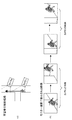
この監視システムの動作を図10を使って説明する。
移動体の特徴情報を抽出した図10(a)の監視カメラ装置Aは、画像撮影手段11で撮影した映像(図10(a’))を映像伝送手段14からモニター装置50に送信する。モニター装置50は、この映像を映像受信手段51で受信して表示手段52に表示する。
【0030】
モニター装置50の監視者は、表示された画像から不審者を発見すると、追跡対象指示手段55から追跡対象の不審者を指示する。モニター装置50の特徴情報交換手段54は、この画像を送信した監視カメラ装置Aの特徴情報交換手段15と通信して、追跡対象指示手段55が指示した追跡対象の特徴情報を取得する(図9の▲1▼の手順)。
次に、モニター装置50の特徴情報交換手段54は、監視カメラ装置Aから取得した追跡対象の特徴情報を各監視カメラ装置A、B、C、Dにブロードキャスト送信する(図9の▲2▼の手順)。各監視カメラ装置A、B、C、Dの特徴情報交換手段54は、この特徴情報を受信して特徴情報比較手段13に出力し、この特徴情報が特徴情報比較手段13のメモリ130に追跡対象情報として登録される。
【0031】
その後の動作は、第1の実施形態と変わりがない。即ち、追跡対象を画面に捉えている監視カメラ装置Aは、追跡対象情報の有効期限を更新しながら、追跡対象が撮影範囲から外れるまで、映像をモニター装置50に送信し続け、追跡対象が撮影範囲から外れると、追跡対象情報を他の監視カメラ装置B、C、Dに送信して、モニター装置50への映像の送信を停止する。
【0032】
また、監視カメラ装置B、C、Dは、モニター装置50から送られた特徴情報を有効期限が切れるまでメモリ130に保持し、その間に追跡対象を画面で捉えたときは、その映像をモニター装置50に送信する。モニター装置50から送られた特徴情報の有効期限が切れた後は、第1の実施形態と同様に、他の監視カメラ装置Aから受信した特徴情報をメモリ130で保持することになる。
【0033】
図10(b)において、監視カメラ装置B、C、Dは、それぞれ移動体を検出するが、特徴情報と一致する不審者を検出した監視カメラ装置Dだけが、その映像(図10(b’))をモニター装置50に送信する。
【0034】
このように、この監視システムでは、監視者が追跡対象を指示し、この指示に応じて各監視カメラ装置が自動的に追跡対象を追跡することができる。そのため、人通りが多い場所等でも、追跡対象を明示的に指定することができ、有効な追跡監視が可能になる。
【0035】
(第3の実施形態)
第3の実施形態では、予め登録された人物以外の不審者だけを追跡する監視システムについて説明する。
このシステムは、図11に示すように、登録されたユーザの特徴情報が蓄積されたユーザ特徴情報データベース70を備えている。その他の構成は第1の実施形態(図1)と変わりがない。
【0036】
このユーザ特徴情報データベース70には、ユーザの特徴情報として、顔画像や、目、鼻、口などの位置、形などの顔の特徴に関する情報、あるいは、虹彩情報など、ユーザを一意に特定可能な情報を記述した登録ユーザリストが格納されている。
また、監視カメラ装置10の特徴情報抽出手段12は、画像撮影手段11が撮影した画像から、これらの特徴情報を抽出する。特徴情報比較手段13は、特徴情報抽出手段12から特徴情報が入力されると、特徴情報交換手段15を介して、ユーザ特徴情報データベース70から登録ユーザリストを取得し(図11の▲1▼の手順)、特徴情報抽出手段12から入力した特徴情報が登録ユーザリストに載っているか否かを判定する。そして、この特徴情報が登録ユーザリストに載っていない場合にのみ、メモリ130にその特徴情報を追跡対象情報として記録する。
【0037】
その後の動作は、第1の実施形態と変わりがない。即ち、追跡対象を画面に捉えている監視カメラ装置Aは、追跡対象が撮影範囲から外れるまで、映像をモニター装置50に送信し続け、追跡対象が撮影範囲から外れると、追跡対象情報を他の監視カメラ装置に送信して、モニター装置50への映像の送信を停止する。
また、他の監視カメラ装置10は、監視カメラ装置Aから受信した特徴情報をメモリ130で保持し、追跡対象を画面に捉えたときに、その映像をモニター装置50に送信する。
【0038】
このように、この監視システムでは、登録ユーザリストに載っていない不審者のみが追跡対象とされ、その不審者が映る監視カメラ装置10の映像だけがモニター装置50に送られて表示または記録される。
また、逆に、登録ユーザリスト(所謂ブラックリスト)に載っている人物のみを追跡対象とし、その人物が映る監視カメラ装置10の映像だけをモニター装置50に送って表示または記録することも可能である。
【0039】
なお、虹彩認証の技術は、日本自動認識システム協会編、瀬戸洋一他著「これでわかったバイオメトリクス」(オーム社)などに記載されている。
【0040】
(第4の実施形態)
第4の実施形態では、認証機能を異にする複数の監視カメラ装置が連携して追跡対象を追跡する監視システムについて説明する。
このシステムでは、図12に示すように、複数の認証機能を備えた高機能監視カメラ装置20と、一つの認証機能を備えた単機能監視カメラ装置30、40とがネットワーク80を介して接続している。
【0041】
高機能監視カメラ装置20は、画像撮影手段11、映像伝送手段14、特徴情報交換手段15の他に、特徴情報を他の監視カメラ装置との間で交換する際に、認識能力についての能力交換を行う特徴情報調停手段16を備え、また、特徴情報抽出手段及び特徴情報比較手段として、例えば、追跡対象の顔に関する認識機能を有する特徴情報抽出手段a(32)及び特徴情報比較手段a(33)と、追跡対象の全体形状に関する認識機能を有する特徴情報抽出手段b(42)及び特徴情報比較手段b(43)とを備えている。
また、単機能監視カメラ装置30は、画像撮影手段11、映像伝送手段14、特徴情報交換手段15、及び、特徴情報調停手段16と、追跡対象の顔に関する認識機能を有する特徴情報抽出手段a(32)と特徴情報比較手段a(33)とを備えている。
【0042】
一方、単機能監視カメラ装置40は、画像撮影手段11、映像伝送手段14、特徴情報交換手段15、及び、特徴情報調停手段16と、追跡対象の全体形状に関する認識機能を有する特徴情報抽出手段b(42)と特徴情報比較手段b(43)とを備えている。
【0043】
次に、この監視システムの動作について説明する。
高機能監視カメラ装置20は、特徴情報交換手段15を通じて、単機能監視カメラ装置30、40に特徴情報を送信する場合、まず、特徴情報調停手段16により、認識能力についての能力交換を行う(図12の▲1▼の手順)。
能力交換は、H.323やSIP(Session Initiation Protocol)などのマルチメディア情報通信プロトコルに搭載される機能であり、相手と共通の通信方式を決定するため、通信の始めに、自分が扱える情報を交換する。
【0044】
例えば、高機能監視カメラ装置20は、通信開始時に、通信開始要求と、高機能監視カメラ装置20が自分で伝送できる特徴情報を列挙した特徴情報形式(顔認識、物体認識)とを単機能監視カメラ装置30、40に送信する。
単機能監視カメラ装置30は、列挙された情報の中から自分が利用できる情報を選択し、通信要求受理と、特徴情報形式(顔認識)とを高機能監視カメラ装置20に返信する。
これを受けて、高機能監視カメラ装置20は、単機能監視カメラ装置30に対しては、特徴情報抽出手段a(32)が抽出した顔認識の特徴情報を単機能監視カメラ装置30に送信する(図12の▲2▼の手順)。
【0045】
一方、単機能監視カメラ装置30は、列挙された情報の中から自分が利用できる情報を選択し、通信要求受理と、特徴情報形式(物体認識)とを高機能監視カメラ装置20に返信する。
これを受けて、高機能監視カメラ装置20は、単機能監視カメラ装置40に対しては、特徴情報抽出手段b(42)が抽出した物体認識の特徴情報を単機能監視カメラ装置40に送信する。
【0046】
このように、この監視システムでは、認証機能を異にする複数の監視カメラ装置が、相互の間で共通して扱うことができる特徴情報を交換しながら、連携して追跡対象を追跡することが可能になる。
【0047】
施設や特定地域を監視する場合には、次のような形態でこの監視システムを適用することにより、効率的な監視を行うことができる。
施設や地域の入口に顔特徴情報(顔認証など特定の部位の高精度な特徴情報)と全体特徴情報(体の形状や色情報などの低精度だが適用範囲の広い特徴情報)とを取得可能な高機能監視カメラ装置を配置し、その他の場所には、全体特徴情報のみが取得可能な単機能監視カメラ装置を配置する。また、第3の実施形態で説明した登録ユーザリストに、施設の利用が許可された会員や地域住民の顔特徴情報を登録する。
【0048】
入口に配置した高機能監視カメラ装置は、入口を通過する人物の顔特徴情報を取得して、登録ユーザリストの顔特徴情報と比較し、登録ユーザリストに載っていない不審者を認識すると、その映像をモニター装置に送信するとともに、各単機能監視カメラ装置に不審者の全体特徴情報を送信する。各単機能監視カメラ装置は、撮影画像の中で不審者の全体特徴情報を捉えた場合に、その映像をモニター装置に送信する。
【0049】
このように、各設置場所に、その場所に合った機能の監視カメラを配置して、各監視カメラを連携させることにより、高度な監視が実現できる。また、高機能カメラを一台だけ使用し、他は低機能カメラを使用することにより、コストが削減できる。
また、同様に、人がよく通る廊下やホールに高機能カメラを一台配置し、人が通らない場所や各部屋には単機能カメラを配置するような応用も可能である。
【0050】
【発明の効果】
以上の説明から明らかなように、本発明の監視システムでは、知能化した複数の監視カメラ装置が連携を取りながら、自律的に追跡対象を追跡し、その映像をモニター装置に伝送する。従って、監視者は、特別の操作を行わなくても、不審者などをモニター上で容易に追跡監視することができる。
【0051】
また、この監視システムでは、不審者が監視カメラの死角に入ったときでも、その後、監視カメラが追跡対象者を映像に捉えた段階で、自動的に不審者の追跡が再開される。そのため、死角が多い空間においても、同じ対象物を追跡し続けることができる。また、監視カメラの設置個数を減らすことも可能である。
【図面の簡単な説明】
【図1】本発明の第1の実施形態における監視システムの構成を示すブロック図
【図2】第1の実施形態における監視カメラ装置の物体切り出しによる画像認識方法を示す説明図
【図3】第1の実施形態における監視カメラ装置の物体情報を抽象化する画像認識方法を示す説明図
【図4】第1の実施形態における監視カメラ装置の顔の特徴情報を抽出する画像認識方法を示す説明図
【図5】第1の実施形態における特徴情報抽出手段の動作を示すフロー図
【図6】第1の実施形態における特徴情報比較手段のメモリ構成を示す図
【図7】第1の実施形態における特徴情報比較手段の動作を示すフロー図
【図8】第1の実施形態における監視システムのモニター表示を説明する図
【図9】本発明の第2の実施形態における監視システムの構成を示すブロック図
【図10】第2の実施形態における監視システムのモニター表示を説明する図
【図11】本発明の第3の実施形態における監視システムの構成を示すブロック図
【図12】本発明の第4の実施形態における監視システムの構成を示すブロック図
【図13】従来の監視システムの構成を示すブロック図
【符号の説明】
1 監視カメラ装置
2 カメラ切り替え装置
3 カメラ切り替え手段
4 動き認識手段
5 カメラ設置情報
6 モニター装置
10 監視カメラ装置
11 画像撮影手段
12 特徴情報抽出手段
13 特徴情報比較手段
14 映像伝送手段
15 特徴情報交換手段
16 特徴情報調停手段
20 高機能監視カメラ装置
30 単機能監視カメラ装置
32 特徴情報抽出手段a
33 特徴情報比較手段a
40 単機能監視カメラ装置
42 特徴情報抽出手段b
43 特徴情報比較手段b
50 モニター装置
51 映像受信手段
52 表示手段
53 記録手段
54 特徴情報交換手段
55 追跡対象指示手段
70 ユーザ特徴情報データベース
80 ネットワーク
130 メモリ[0001]
BACKGROUND OF THE INVENTION
The present invention relates to a monitoring system including a plurality of monitoring cameras and a monitoring camera used in the system, and particularly to monitoring a moving person or the like by linking a plurality of cameras.
[0002]
[Prior art]
2. Description of the Related Art Conventionally, various systems have been developed that automate the monitoring of people entering and leaving a building using a surveillance camera.
[0003]
Japanese Patent Application Laid-Open No. 2000-163600 describes a monitoring system that extracts facial features from an image shown on a monitoring camera and compares them with a face mask registered in a database. In this system, the control means that analyzes the image signal of the surveillance camera confirms the position of the person's face reflected in the surveillance camera, and controls the pan, tilt, and zoom of the surveillance camera so that the face is located at the center of the screen And track the movement of the face. Then, the contour lines of the eyes, nose, mouth, and eyebrows are extracted from the stop image of the face, the feature points of the face are extracted based on the contour lines, and compared with the face masks registered in the database.
[0004]
Japanese Patent Laid-Open No. 6-325180 describes a system for tracking and monitoring a moving body using a plurality of cameras. In this system, as shown in FIG. 13, a plurality of monitoring
[0005]
[Problems to be solved by the invention]
However, when tracking the movement of a suspicious person indoors or outdoors, the range that can be tracked by one camera is limited even if a surveillance camera capable of controlling pan, tilt and zoom is used. In addition, even when using multiple cameras, the method of detecting the movement of a moving object and determining the switching destination camera loses information on the position and movement of the moving object when a blind spot occurs. There is a problem that cannot continue.
[0006]
Therefore, it is impossible to track a moving object in an environment where it is difficult to install cameras comprehensively such as a wide place or a complicated place. In addition, when a camera breaks down, a blind spot is generated in the same manner, so that tracking cannot be continued.
Also, with this method, there is a problem that it is not easy to move or add a monitoring camera because it is necessary to set the positional relationship of the monitoring camera and determine the switching destination camera.
[0007]
The present invention solves such a conventional problem, and provides a monitoring system capable of tracking and monitoring a moving body in cooperation with a plurality of cameras, and an object of providing the monitoring camera. It is said.
[0008]
[Means for Solving the Problems]
The present invention relates to a surveillance camera device of a monitoring system in which a plurality of monitoring camera device captures an image of the moving object to be tracked in conjunction, an image capturing means for outputting a digital video data by capturing an image, the Feature information extracting means for outputting input information, which is a result of extracting feature information indicating the feature of the moving object in the digital video data, and feature information for exchanging the feature information of the moving object to be tracked with another monitoring camera device When the feature information exchanging means and the feature information exchanging means exchange the feature information of the moving object to be tracked with the other monitoring camera device, the feature is transmitted by exchanging the capability regarding the image recognition function with the other monitoring camera device. Characteristic information arbitration means for determining the type of information.
[0010]
In this monitoring system, since a plurality of monitoring cameras pass the feature information of the tracking target between each other, and each monitoring camera tracks the tracking target using the feature information, the tracking target is continuously tracked even in a space with many blind spots. be able to.
[0011]
DETAILED DESCRIPTION OF THE INVENTION
(First embodiment)
The monitoring camera device of the monitoring system according to the first embodiment of the present invention has a function of recognizing a moving body (person) from a captured image and a function of exchanging information of the recognized person between the monitoring camera devices. Yes.
As shown in FIG. 1, the monitoring system includes a plurality of monitoring
[0012]
Each of the monitoring camera devices 10 (herein, the monitoring camera device A and the monitoring camera device B) has an
In addition, the
[0013]
The feature information extracted by the feature
These feature information extraction methods are widely known. FIG. 2 schematically shows a method for cutting out image data of a moving object from an image. In this case, the normal image (FIG. 2 (a)) is accumulated in the frame memory, the difference from the image including the moving object (FIG. 2 (b)) is taken, and the object of the portion where the difference exists is extracted. Only the moving object is extracted (FIG. 2C).
[0014]
FIG. 3 schematically shows how to create information such as the shape, color, and size that identifies the moving body from the extracted moving body image. In this case, the screen is divided into blocks (FIG. 3A), representative colors of each block are extracted, and the information on the moving object is abstracted.
FIG. 4 schematically shows how to create facial feature information, and extracts information on the shape and position of facial components, and acquires information on the size, position, and shape of eyes, nose, and mouth. To do. This method is described in detail in Japanese Patent Laid-Open No. 2000-163600 and Japanese Patent Laid-Open No. 2001-256696 described above.
[0015]
Next, the operation of this monitoring system will be described.
The
The flowchart of FIG. 5 shows the processing procedure of the feature information extraction means 12.
Step 1: The feature information extraction means 12 receives image data from the
Step 2: Identify whether the moving object is included in the image, and if there is a moving object,
Step 3: Extract feature information,
Step 4: This feature information is output to the feature information comparison means 13.
Step 5: In
[0016]
As shown in FIG. 6, the feature
The feature
[0017]
The flowchart of FIG. 7 shows the processing procedure of the feature information comparison means 13.
Step 10: The feature information comparison means 13 inputs the information,
Step 11: Identify whether the expiration date of the
Step 12: Erase all records in
Step 13: If the video transmission means 14 is transmitting video,
Step 14: Instruct to stop video transmission.
[0018]
Step 15: If the expiration date of the
Step 16: If there is no tracking target in this
Step 17: The feature information is registered as the tracking target information in the
[0019]
In
Step 18: Identify the type of input information. When the input information is feature information,
Step 20: If there is no tracking target in this
Step 17: The inputted feature information is registered in the
In step 20, when the tracking target exists (the tracking target information exists in the memory 130),
Step 21: The inputted feature information is compared with the feature information to be tracked to identify whether or not they are the same.
[0020]
A method for comparing images to determine identity is well known. In a simple method, for example, when the feature information is image data of a moving body or abstracted data thereof,
1. 1. Correct the size and orientation of image data by scaling, rotation, etc. 2. Calculate the difference between the image data. If the calculation result is within the specified range, the determination can be made according to the procedure of determining that they are the same.
[0021]
In addition, other feature information can be converted into information that can be expressed by multi-dimensional numerical values. Therefore, the identity can be determined by using a weighted square sum of the difference values of each dimension element.
That is, the identity of the feature information (x1, y1, z1) and (x2, y2, z2) is
a1 * (x1-x2) 2 + a2 * (y1-y2) 2 + a3 * (z1-z2) 2
(However, a1, a2, and a3 are determined by the type of feature information)
Are smaller than a certain value, it is determined that they are the same.
[0022]
For more strict methods, see the following literature by Takeshi Aiin and Tomoharu Nagao, “Image Processing and Recognition”, Shosodo Co., Ltd. Chapter 6 “Feature Space and Clustering”
Chapter 7 “Pattern Matching”
It is shown in.
[0023]
Now, in step 21, when the input feature information and the feature information of the tracking target are the same,
Step 22: The tracking target information is updated to the input feature information, and the expiration date is updated to the current time + the specified value.
Step 23: If the video transmission means 14 is not transmitting video,
Step 24: The video transmission means 14 is started to transmit the video shot by the image shooting means 11.
[0024]
In
Step 19: Identifying whether or not the
Step 26: If the video transmission means 14 is transmitting video,
Step 27: The video transmission means 14 stops video transmission,
Step 28: The tracking information registered in the
Also, in step 21, even if the input feature information is different from the feature information of the tracking target, the tracking target moving body appears to have disappeared from the screen, so the procedure of steps 26 to 28 is performed.
The feature
[0025]
Thus, in this monitoring system, when the monitoring camera device A loses track of the tracking target, the feature information extracted by the feature information extraction means 12 is transmitted to another monitoring camera device using the feature
[0026]
FIG. 8 shows an image (shown in FIG. 8) displayed on the display screen of the
[0027]
Thus, in this monitoring system, even in a space with many blind spots, a plurality of monitoring camera devices can track the same object while exchanging information with each other.
[0028]
(Second Embodiment)
In the second embodiment, a monitoring system capable of specifying a tracking target on the monitor device side will be described.
As shown in FIG. 9, the monitor device of this system includes feature
[0029]
The operation of this monitoring system will be described with reference to FIG.
The monitoring camera device A of FIG. 10A from which the feature information of the moving body is extracted transmits the video image (FIG. 10A ′) captured by the
[0030]
When the monitor of the
Next, the feature
[0031]
Subsequent operations are the same as those in the first embodiment. That is, the monitoring camera device A that captures the tracking target on the screen updates the expiration date of the tracking target information and continues to transmit the video to the
[0032]
The monitoring camera devices B, C, and D hold the feature information sent from the
[0033]
In FIG. 10B, each of the monitoring camera devices B, C, and D detects a moving body, but only the monitoring camera device D that detects a suspicious person that matches the feature information displays the video (FIG. 10B ′). )) Is transmitted to the
[0034]
As described above, in this monitoring system, the monitor can instruct the tracking target, and each monitoring camera device can automatically track the tracking target in accordance with this instruction. For this reason, it is possible to explicitly specify a tracking target even in a place where there is a lot of traffic, and effective tracking monitoring becomes possible.
[0035]
(Third embodiment)
In the third embodiment, a monitoring system for tracking only a suspicious person other than a person registered in advance will be described.
As shown in FIG. 11, this system includes a user
[0036]
In this user feature
Further, the feature
[0037]
Subsequent operations are the same as those in the first embodiment. That is, the monitoring camera device A that captures the tracking target on the screen continues to transmit the video to the
Further, the other
[0038]
In this way, in this monitoring system, only suspicious persons who are not on the registered user list are tracked, and only the video of the
Conversely, only a person on the registered user list (so-called black list) can be tracked, and only the video of the
[0039]
The technology for iris authentication is described in the Japan Automatic Recognition System Association, Yoichi Seto et al., “Biometrics Identified by This” (Ohm).
[0040]
(Fourth embodiment)
In the fourth embodiment, a monitoring system in which a plurality of monitoring camera devices having different authentication functions cooperate to track a tracking target will be described.
In this system, as shown in FIG. 12, a high-function surveillance camera device 20 having a plurality of authentication functions and a single-function
[0041]
In addition to the image capturing means 11, the video transmission means 14, and the feature
Further, the single-function
[0042]
On the other hand, the single-function monitoring camera device 40 includes an
[0043]
Next, the operation of this monitoring system will be described.
When the high-function surveillance camera device 20 transmits feature information to the single-function
The capacity exchange is This function is installed in a multimedia information communication protocol such as H.323 or SIP (Session Initiation Protocol), and exchanges information that can be handled at the beginning of communication in order to determine a common communication method with the other party.
[0044]
For example, the high-function monitoring camera device 20 performs single-function monitoring of a communication start request and feature information format (face recognition, object recognition) enumerating feature information that can be transmitted by the high-function monitoring camera device 20 by itself. It transmits to the
The single-function
In response to this, the high-function surveillance camera device 20 transmits the face recognition feature information extracted by the feature information extraction means a (32) to the single-function
[0045]
On the other hand, the single-function
In response to this, the high-function surveillance camera device 20 transmits the feature information of object recognition extracted by the feature information extraction unit b (42) to the single-function surveillance camera device 40 to the single-function surveillance camera device 40. .
[0046]
As described above, in this monitoring system, a plurality of monitoring camera devices having different authentication functions can track the tracking target in cooperation while exchanging feature information that can be handled in common among each other. It becomes possible.
[0047]
When monitoring facilities and specific areas, efficient monitoring can be performed by applying this monitoring system in the following manner.
Facial feature information (high-precision feature information of specific parts such as face authentication) and overall feature information (low-precision feature information such as body shape and color information but wide application range) can be acquired at the entrance of facilities and regions A high-function surveillance camera device is disposed, and a single-function surveillance camera device capable of acquiring only the entire feature information is disposed in other places. In addition, the facial feature information of members and local residents who are permitted to use the facility is registered in the registered user list described in the third embodiment.
[0048]
The high-function surveillance camera device arranged at the entrance acquires the facial feature information of the person passing through the entrance, compares it with the facial feature information of the registered user list, and recognizes a suspicious person who is not on the registered user list. The video is transmitted to the monitor device, and the entire characteristic information of the suspicious person is transmitted to each single-function monitoring camera device. When each single-function monitoring camera device captures the entire characteristic information of the suspicious person in the captured image, the single-function monitoring camera device transmits the video to the monitor device.
[0049]
In this way, advanced monitoring can be realized by disposing monitoring cameras having functions suitable for each installation location and linking the respective monitoring cameras to each installation location. In addition, the cost can be reduced by using only one high-function camera and the other using a low-function camera.
Similarly, an application in which one high-function camera is arranged in a corridor or hall where people often pass and a single-function camera is arranged in a place where each person cannot pass or in each room is possible.
[0050]
【The invention's effect】
As is clear from the above description, in the surveillance system of the present invention, a plurality of intelligent surveillance camera devices autonomously track the tracking target and cooperate with each other to transmit the video to the monitor device. Therefore, the supervisor can easily follow and monitor a suspicious person or the like on the monitor without performing any special operation.
[0051]
In this monitoring system, even when the suspicious person enters the blind spot of the surveillance camera, the suspicious person is automatically traced after the surveillance camera captures the person to be tracked in the video. Therefore, the same object can be tracked even in a space with many blind spots. It is also possible to reduce the number of surveillance cameras installed.
[Brief description of the drawings]
FIG. 1 is a block diagram showing a configuration of a monitoring system according to a first embodiment of the present invention. FIG. 2 is an explanatory diagram showing an image recognition method by object cutout of the monitoring camera device according to the first embodiment. Explanatory drawing which shows the image recognition method which abstracts the object information of the surveillance camera apparatus in 1 embodiment. FIG. 4 is explanatory drawing which shows the image recognition method which extracts the facial feature information of the surveillance camera apparatus in 1st Embodiment. FIG. 5 is a flowchart showing the operation of the feature information extracting means in the first embodiment. FIG. 6 is a diagram showing the memory configuration of the feature information comparing means in the first embodiment. FIG. 8 is a flowchart for explaining the monitor display of the monitoring system in the first embodiment. FIG. 9 shows the configuration of the monitoring system in the second embodiment of the present invention. FIG. 10 is a diagram for explaining the monitor display of the monitoring system in the second embodiment. FIG. 11 is a block diagram showing the configuration of the monitoring system in the third embodiment of the present invention. FIG. 13 is a block diagram showing the configuration of a monitoring system according to a fourth embodiment. FIG. 13 is a block diagram showing the configuration of a conventional monitoring system.
DESCRIPTION OF
10 Surveillance camera device
11 Image capture means
12 Feature information extraction means
13 Feature information comparison means
14 Video transmission means
15 Feature information exchange means
16 Feature information mediation means
20 High-function surveillance camera device
30 single-function surveillance camera device
32 Feature information extraction means a
33 Feature information comparison means a
40 single-function surveillance camera device
42 Feature information extraction means b
43 Feature information comparison means b
50 Monitor equipment
51 Video reception means
52 Display means
53 Recording means
54 Feature Information Exchange Method
55 Tracking target instruction means
70 User characteristic information database
80 network
130 memory
Claims (1)
映像を撮影してデジタル映像データを出力する画像撮影手段と、
前記デジタル映像データの中の移動体の特徴を示す特徴情報の抽出結果である入力情報を出力する特徴情報抽出手段と、
追跡対象の移動体の特徴情報を、他の監視カメラ装置と交換する特徴情報交換手段と、
前記特徴情報交換手段が他の監視カメラ装置と追跡対象の移動体の特徴情報を交換するとき、前記他の監視カメラ装置と画像認識機能に関する能力交換を行うことで、伝送する特徴情報の種類を決定する特徴情報調停手段と、を備える監視カメラ装置。A surveillance camera device of a surveillance system in which a plurality of surveillance camera devices cooperate to capture an image of a moving object to be tracked,
Image photographing means for photographing video and outputting digital video data;
Feature information extracting means for outputting input information that is a result of extracting feature information indicating the characteristics of the moving object in the digital video data;
Feature information exchanging means for exchanging the feature information of the tracking target moving body with another monitoring camera device;
When the feature information exchanging means exchanges the feature information of the tracking target moving body with another monitoring camera device, the type of feature information to be transmitted is exchanged by exchanging the capability regarding the image recognition function with the other monitoring camera device. A surveillance camera device comprising: feature information arbitration means for determining.
Priority Applications (2)
| Application Number | Priority Date | Filing Date | Title |
|---|---|---|---|
| JP2002131308A JP3999561B2 (en) | 2002-05-07 | 2002-05-07 | Surveillance system and surveillance camera |
| US10/430,492 US7227569B2 (en) | 2002-05-07 | 2003-05-06 | Surveillance system and a surveillance camera |
Applications Claiming Priority (1)
| Application Number | Priority Date | Filing Date | Title |
|---|---|---|---|
| JP2002131308A JP3999561B2 (en) | 2002-05-07 | 2002-05-07 | Surveillance system and surveillance camera |
Publications (3)
| Publication Number | Publication Date |
|---|---|
| JP2003324720A JP2003324720A (en) | 2003-11-14 |
| JP2003324720A5 JP2003324720A5 (en) | 2005-09-15 |
| JP3999561B2 true JP3999561B2 (en) | 2007-10-31 |
Family
ID=29543989
Family Applications (1)
| Application Number | Title | Priority Date | Filing Date |
|---|---|---|---|
| JP2002131308A Expired - Lifetime JP3999561B2 (en) | 2002-05-07 | 2002-05-07 | Surveillance system and surveillance camera |
Country Status (2)
| Country | Link |
|---|---|
| US (1) | US7227569B2 (en) |
| JP (1) | JP3999561B2 (en) |
Cited By (4)
| Publication number | Priority date | Publication date | Assignee | Title |
|---|---|---|---|---|
| JP2010238187A (en) * | 2009-03-31 | 2010-10-21 | Sogo Keibi Hosho Co Ltd | Security system and security method |
| JP2010238188A (en) * | 2009-03-31 | 2010-10-21 | Sogo Keibi Hosho Co Ltd | Security system and security method |
| WO2011010490A1 (en) | 2009-07-22 | 2011-01-27 | オムロン株式会社 | Surveillance camera terminal |
| JP2018133639A (en) * | 2017-02-14 | 2018-08-23 | 三菱電機株式会社 | Cyber physical security system |
Families Citing this family (144)
| Publication number | Priority date | Publication date | Assignee | Title |
|---|---|---|---|---|
| US7292723B2 (en) * | 2003-02-26 | 2007-11-06 | Walker Digital, Llc | System for image analysis in a network that is structured with multiple layers and differentially weighted neurons |
| JP4339762B2 (en) * | 2003-09-02 | 2009-10-07 | 富士フイルム株式会社 | Authentication system and program |
| JP4476744B2 (en) * | 2003-09-02 | 2010-06-09 | 富士フイルム株式会社 | Imaging system and program |
| JP2007504562A (en) * | 2003-09-04 | 2007-03-01 | サーノフ コーポレーション | Method and apparatus for performing iris authentication from a single image |
| JP2005159691A (en) * | 2003-11-26 | 2005-06-16 | Hitachi Ltd | Supervisory system |
| JP2007520934A (en) * | 2003-12-24 | 2007-07-26 | ウオーカー ディジタル、エルエルシー | Method and apparatus for automatically capturing and managing images |
| JP4536401B2 (en) * | 2004-03-04 | 2010-09-01 | パナソニック株式会社 | Monitoring device and monitoring device status monitoring method |
| JP4369326B2 (en) * | 2004-08-19 | 2009-11-18 | 株式会社日立製作所 | Facility information providing system and facility information providing method |
| JP4587166B2 (en) * | 2004-09-14 | 2010-11-24 | キヤノン株式会社 | Moving body tracking system, photographing apparatus, and photographing method |
| ITMN20050003A1 (en) * | 2005-01-14 | 2006-07-15 | Renato Grassi | ANTI-ROBBERY CAMERA |
| US8606383B2 (en) * | 2005-01-31 | 2013-12-10 | The Invention Science Fund I, Llc | Audio sharing |
| US20060170956A1 (en) | 2005-01-31 | 2006-08-03 | Jung Edward K | Shared image devices |
| US9910341B2 (en) | 2005-01-31 | 2018-03-06 | The Invention Science Fund I, Llc | Shared image device designation |
| US20060174203A1 (en) | 2005-01-31 | 2006-08-03 | Searete Llc, A Limited Liability Corporation Of The State Of Delaware | Viewfinder for shared image device |
| US7920169B2 (en) | 2005-01-31 | 2011-04-05 | Invention Science Fund I, Llc | Proximity of shared image devices |
| US7876357B2 (en) | 2005-01-31 | 2011-01-25 | The Invention Science Fund I, Llc | Estimating shared image device operational capabilities or resources |
| JP2006209585A (en) * | 2005-01-31 | 2006-08-10 | Mitsubishi Electric Corp | Crime prevention system |
| US9124729B2 (en) | 2005-01-31 | 2015-09-01 | The Invention Science Fund I, Llc | Shared image device synchronization or designation |
| US20060221197A1 (en) * | 2005-03-30 | 2006-10-05 | Jung Edward K | Image transformation estimator of an imaging device |
| US9325781B2 (en) | 2005-01-31 | 2016-04-26 | Invention Science Fund I, Llc | Audio sharing |
| US8902320B2 (en) * | 2005-01-31 | 2014-12-02 | The Invention Science Fund I, Llc | Shared image device synchronization or designation |
| US9489717B2 (en) | 2005-01-31 | 2016-11-08 | Invention Science Fund I, Llc | Shared image device |
| US9082456B2 (en) | 2005-01-31 | 2015-07-14 | The Invention Science Fund I Llc | Shared image device designation |
| JP4559874B2 (en) * | 2005-03-01 | 2010-10-13 | ティーオーエー株式会社 | Motion tracking device |
| US7801328B2 (en) * | 2005-03-31 | 2010-09-21 | Honeywell International Inc. | Methods for defining, detecting, analyzing, indexing and retrieving events using video image processing |
| US7760908B2 (en) * | 2005-03-31 | 2010-07-20 | Honeywell International Inc. | Event packaged video sequence |
| US9967424B2 (en) | 2005-06-02 | 2018-05-08 | Invention Science Fund I, Llc | Data storage usage protocol |
| US20070222865A1 (en) | 2006-03-15 | 2007-09-27 | Searete Llc, A Limited Liability Corporation Of The State Of Delaware | Enhanced video/still image correlation |
| US9093121B2 (en) | 2006-02-28 | 2015-07-28 | The Invention Science Fund I, Llc | Data management of an audio data stream |
| US9942511B2 (en) | 2005-10-31 | 2018-04-10 | Invention Science Fund I, Llc | Preservation/degradation of video/audio aspects of a data stream |
| US7872675B2 (en) * | 2005-06-02 | 2011-01-18 | The Invention Science Fund I, Llc | Saved-image management |
| US8072501B2 (en) * | 2005-10-31 | 2011-12-06 | The Invention Science Fund I, Llc | Preservation and/or degradation of a video/audio data stream |
| US8964054B2 (en) | 2006-08-18 | 2015-02-24 | The Invention Science Fund I, Llc | Capturing selected image objects |
| US9621749B2 (en) | 2005-06-02 | 2017-04-11 | Invention Science Fund I, Llc | Capturing selected image objects |
| US8253821B2 (en) * | 2005-10-31 | 2012-08-28 | The Invention Science Fund I, Llc | Degradation/preservation management of captured data |
| US9451200B2 (en) | 2005-06-02 | 2016-09-20 | Invention Science Fund I, Llc | Storage access technique for captured data |
| US8681225B2 (en) | 2005-06-02 | 2014-03-25 | Royce A. Levien | Storage access technique for captured data |
| US9076208B2 (en) | 2006-02-28 | 2015-07-07 | The Invention Science Fund I, Llc | Imagery processing |
| US10003762B2 (en) | 2005-04-26 | 2018-06-19 | Invention Science Fund I, Llc | Shared image devices |
| US9819490B2 (en) | 2005-05-04 | 2017-11-14 | Invention Science Fund I, Llc | Regional proximity for shared image device(s) |
| US9001215B2 (en) | 2005-06-02 | 2015-04-07 | The Invention Science Fund I, Llc | Estimating shared image device operational capabilities or resources |
| US9167195B2 (en) | 2005-10-31 | 2015-10-20 | Invention Science Fund I, Llc | Preservation/degradation of video/audio aspects of a data stream |
| US9191611B2 (en) | 2005-06-02 | 2015-11-17 | Invention Science Fund I, Llc | Conditional alteration of a saved image |
| US7782365B2 (en) | 2005-06-02 | 2010-08-24 | Searete Llc | Enhanced video/still image correlation |
| US8233042B2 (en) * | 2005-10-31 | 2012-07-31 | The Invention Science Fund I, Llc | Preservation and/or degradation of a video/audio data stream |
| US20060269090A1 (en) * | 2005-05-27 | 2006-11-30 | Roman Sapiejewski | Supra-aural headphone noise reducing |
| JP4947936B2 (en) * | 2005-08-11 | 2012-06-06 | ソニー株式会社 | Monitoring system and management device |
| EP1762994B1 (en) * | 2005-09-07 | 2008-12-10 | Siemens Building Technologies Fire & Security Products GmbH & Co. oHG | Intelligent surveillance camera |
| US20070071404A1 (en) * | 2005-09-29 | 2007-03-29 | Honeywell International Inc. | Controlled video event presentation |
| US20070120980A1 (en) * | 2005-10-31 | 2007-05-31 | Searete Llc, A Limited Liability Corporation Of The State Of Delaware | Preservation/degradation of video/audio aspects of a data stream |
| JP4700477B2 (en) * | 2005-11-15 | 2011-06-15 | 株式会社日立製作所 | MOBILE BODY MONITORING SYSTEM AND MOBILE BODY FEATURE CALCULATION DEVICE |
| JP2007158421A (en) * | 2005-11-30 | 2007-06-21 | Matsushita Electric Ind Co Ltd | Monitoring camera system and face image tracing recording method |
| KR100744668B1 (en) | 2006-01-27 | 2007-08-02 | 덕성여자대학교 산학협력단 | Multiple person surveillance system using networked cameras |
| DE102006010955B3 (en) * | 2006-03-03 | 2007-10-04 | Siemens Ag | Method for visually monitoring a room area |
| JP2007241377A (en) * | 2006-03-06 | 2007-09-20 | Sony Corp | Retrieval system, imaging apparatus, data storage device, information processor, picked-up image processing method, information processing method, and program |
| CN101401426B (en) | 2006-03-15 | 2010-12-01 | 欧姆龙株式会社 | Tracking device, tracking method |
| JP2007336035A (en) * | 2006-06-13 | 2007-12-27 | Matsushita Electric Ind Co Ltd | Network camera, and network camera system |
| WO2007147171A2 (en) * | 2006-06-16 | 2007-12-21 | Verificon Corporation | Scalable clustered camera system and method for multiple object tracking |
| JP2008035095A (en) * | 2006-07-27 | 2008-02-14 | Sony Corp | Monitoring apparatus, monitoring system, monitoring method and program |
| JP4148285B2 (en) * | 2006-07-27 | 2008-09-10 | ソニー株式会社 | Monitoring device, filter calibration method, and filter calibration program |
| US8121356B2 (en) * | 2006-09-15 | 2012-02-21 | Identix Incorporated | Long distance multimodal biometric system and method |
| US9172918B2 (en) * | 2007-02-02 | 2015-10-27 | Honeywell International Inc. | Systems and methods for managing live video data |
| US8760519B2 (en) * | 2007-02-16 | 2014-06-24 | Panasonic Corporation | Threat-detection in a distributed multi-camera surveillance system |
| KR101187901B1 (en) * | 2007-07-03 | 2012-10-05 | 삼성테크윈 주식회사 | System for intelligent surveillance and method for controlling thereof |
| WO2009034465A1 (en) * | 2007-09-12 | 2009-03-19 | Digisensory Technologies Pty Ltd | Smart network camera system-on-a-chip |
| JP4959535B2 (en) * | 2007-12-13 | 2012-06-27 | 株式会社日立製作所 | Imaging device |
| US8693738B2 (en) | 2008-01-29 | 2014-04-08 | Canon Kabushiki Kaisha | Imaging processing system and method and management apparatus |
| KR101592889B1 (en) | 2008-03-03 | 2016-02-11 | 아비길론 페이턴트 홀딩 2 코포레이션 | Object matching for tracking, indexing, and search |
| JP2009296331A (en) * | 2008-06-05 | 2009-12-17 | Hitachi Ltd | Security system |
| KR100964726B1 (en) | 2008-07-14 | 2010-06-21 | 한국산업기술대학교산학협력단 | Method for tracking moving objects using characteristics of moving objects in image camera system |
| TW201006230A (en) * | 2008-07-24 | 2010-02-01 | Novatek Microelectronics Corp | Static image presentation method |
| KR101324221B1 (en) * | 2008-08-27 | 2013-11-06 | 삼성테크윈 주식회사 | System for tracking object using capturing and method thereof |
| JP5294801B2 (en) * | 2008-10-30 | 2013-09-18 | 三菱電機株式会社 | Air conditioner |
| US9740921B2 (en) | 2009-02-26 | 2017-08-22 | Tko Enterprises, Inc. | Image processing sensor systems |
| US9293017B2 (en) * | 2009-02-26 | 2016-03-22 | Tko Enterprises, Inc. | Image processing sensor systems |
| US9277878B2 (en) * | 2009-02-26 | 2016-03-08 | Tko Enterprises, Inc. | Image processing sensor systems |
| US8878931B2 (en) | 2009-03-04 | 2014-11-04 | Honeywell International Inc. | Systems and methods for managing video data |
| US8320617B2 (en) * | 2009-03-27 | 2012-11-27 | Utc Fire & Security Americas Corporation, Inc. | System, method and program product for camera-based discovery of social networks |
| JP5227911B2 (en) * | 2009-07-22 | 2013-07-03 | 株式会社日立国際電気 | Surveillance video retrieval device and surveillance system |
| US8908033B2 (en) * | 2009-09-29 | 2014-12-09 | Avaya Inc. | Utilizing presence information for the purpose of enhanced surveillance |
| KR101136366B1 (en) * | 2010-02-26 | 2012-04-18 | 주식회사 비츠로시스 | Auto object tracking system |
| KR101155184B1 (en) | 2010-04-01 | 2012-06-13 | 대덕대학산학협력단 | Visual tracking system using collaboration of double shapshot means and tracking method thereof |
| KR101130034B1 (en) | 2010-04-14 | 2012-03-28 | 부산대학교 산학협력단 | Multiple camera system |
| TW201138466A (en) * | 2010-04-23 | 2011-11-01 | Hon Hai Prec Ind Co Ltd | Video camera and method for monitoring videos of a person or an object |
| JP5721345B2 (en) * | 2010-05-17 | 2015-05-20 | キヤノン株式会社 | Image detection system, image detection method, and image control program |
| JP5334326B2 (en) | 2010-06-30 | 2013-11-06 | パナソニック株式会社 | Pre-recorded data storage device and pre-recorded data storage method |
| KR101224017B1 (en) * | 2011-04-21 | 2013-01-21 | 강원대학교산학협력단 | System for monitoring intelligently image |
| CZ303854B6 (en) * | 2011-05-16 | 2013-05-29 | Vysoké ucení technické v Brne | Decentralized supervisory network enabling request and analysis of supervisory data |
| US20130136298A1 (en) * | 2011-11-29 | 2013-05-30 | General Electric Company | System and method for tracking and recognizing people |
| JP5861420B2 (en) * | 2011-12-05 | 2016-02-16 | 株式会社ニコン | Electronic camera |
| JP5766625B2 (en) * | 2012-01-16 | 2015-08-19 | 株式会社東芝 | Camera device |
| JP5894807B2 (en) * | 2012-01-25 | 2016-03-30 | 株式会社日立国際電気 | Surveillance device, surveillance camera system, and video transmission method |
| US9615015B2 (en) * | 2012-01-27 | 2017-04-04 | Disney Enterprises, Inc. | Systems methods for camera control using historical or predicted event data |
| KR101332820B1 (en) | 2012-02-22 | 2013-11-27 | 주식회사 티앤이에스 | System and Method for Tracking Object, Apparatus for Object Management and Driving Method Thereof, Image Device and Driving Method Thereof |
| JP2013192154A (en) | 2012-03-15 | 2013-09-26 | Omron Corp | Monitoring device, reliability calculation program and reliability calculation method |
| JP2012128877A (en) * | 2012-03-19 | 2012-07-05 | Toshiba Corp | Suspicious behavior detection system and method |
| JP6141079B2 (en) | 2013-04-08 | 2017-06-07 | キヤノン株式会社 | Image processing system, image processing apparatus, control method therefor, and program |
| JP2015088095A (en) * | 2013-11-01 | 2015-05-07 | 株式会社ソニー・コンピュータエンタテインメント | Information processor and information processing method |
| KR20150071504A (en) * | 2013-12-18 | 2015-06-26 | 한국전자통신연구원 | Auto changing system for camera tracking control authority and auto changing method for camera tracking control authority thereof |
| JP6403784B2 (en) * | 2014-08-25 | 2018-10-10 | 株式会社日立国際電気 | Surveillance camera system |
| WO2016046780A1 (en) * | 2014-09-25 | 2016-03-31 | Micheli, Cesare | Surveillance method, device and system |
| CN104320623B (en) * | 2014-11-03 | 2017-09-15 | 四川理工学院 | A kind of method that intelligent monitor system recording exceptional target moves route |
| JP6572535B2 (en) * | 2014-12-10 | 2019-09-11 | 株式会社リコー | Image recognition system, server device, and image recognition method |
| CN104853150A (en) * | 2015-02-11 | 2015-08-19 | 居锦武 | Multi-camera objective cooperatively tracking technology |
| WO2016132769A1 (en) * | 2015-02-19 | 2016-08-25 | シャープ株式会社 | Imaging device, control method for imaging device, and control program |
| WO2016151932A1 (en) * | 2015-03-20 | 2016-09-29 | 日本電気株式会社 | Monitoring system, monitoring method, and monitoring program |
| JP6627365B2 (en) * | 2015-09-24 | 2020-01-08 | 富士通株式会社 | Information processing method, information processing apparatus, and program |
| JP6176306B2 (en) * | 2015-10-30 | 2017-08-09 | 株式会社ニコン | Electronic camera and program |
| US10043058B2 (en) * | 2016-03-09 | 2018-08-07 | International Business Machines Corporation | Face detection, representation, and recognition |
| US11216847B2 (en) | 2016-03-22 | 2022-01-04 | Sensormatic Electronics, LLC | System and method for retail customer tracking in surveillance camera network |
| US10475315B2 (en) | 2016-03-22 | 2019-11-12 | Sensormatic Electronics, LLC | System and method for configuring surveillance cameras using mobile computing devices |
| US10347102B2 (en) | 2016-03-22 | 2019-07-09 | Sensormatic Electronics, LLC | Method and system for surveillance camera arbitration of uplink consumption |
| US10192414B2 (en) | 2016-03-22 | 2019-01-29 | Sensormatic Electronics, LLC | System and method for overlap detection in surveillance camera network |
| US10764539B2 (en) | 2016-03-22 | 2020-09-01 | Sensormatic Electronics, LLC | System and method for using mobile device of zone and correlated motion detection |
| US10318836B2 (en) | 2016-03-22 | 2019-06-11 | Sensormatic Electronics, LLC | System and method for designating surveillance camera regions of interest |
| US10665071B2 (en) | 2016-03-22 | 2020-05-26 | Sensormatic Electronics, LLC | System and method for deadzone detection in surveillance camera network |
| US10733231B2 (en) | 2016-03-22 | 2020-08-04 | Sensormatic Electronics, LLC | Method and system for modeling image of interest to users |
| US11601583B2 (en) | 2016-03-22 | 2023-03-07 | Johnson Controls Tyco IP Holdings LLP | System and method for controlling surveillance cameras |
| US9965680B2 (en) | 2016-03-22 | 2018-05-08 | Sensormatic Electronics, LLC | Method and system for conveying data from monitored scene via surveillance cameras |
| WO2017163282A1 (en) | 2016-03-25 | 2017-09-28 | パナソニックIpマネジメント株式会社 | Monitoring device and monitoring system |
| US10957171B2 (en) | 2016-07-11 | 2021-03-23 | Google Llc | Methods and systems for providing event alerts |
| US10380429B2 (en) | 2016-07-11 | 2019-08-13 | Google Llc | Methods and systems for person detection in a video feed |
| JP6885682B2 (en) * | 2016-07-15 | 2021-06-16 | パナソニックi−PROセンシングソリューションズ株式会社 | Monitoring system, management device, and monitoring method |
| US10331960B2 (en) | 2017-05-10 | 2019-06-25 | Fotonation Limited | Methods for detecting, identifying and displaying object information with a multi-camera vision system |
| US11615566B2 (en) | 2017-05-10 | 2023-03-28 | Fotonation Limited | Multi-camera vehicle vision system and method |
| US10740627B2 (en) | 2017-05-10 | 2020-08-11 | Fotonation Limited | Multi-camera vision system and method of monitoring |
| US10250812B2 (en) | 2017-05-17 | 2019-04-02 | Caterpillar Inc. | Display system for machine |
| US11783010B2 (en) | 2017-05-30 | 2023-10-10 | Google Llc | Systems and methods of person recognition in video streams |
| US10599950B2 (en) | 2017-05-30 | 2020-03-24 | Google Llc | Systems and methods for person recognition data management |
| US10810414B2 (en) | 2017-07-06 | 2020-10-20 | Wisconsin Alumni Research Foundation | Movement monitoring system |
| US10482613B2 (en) | 2017-07-06 | 2019-11-19 | Wisconsin Alumni Research Foundation | Movement monitoring system |
| US11450148B2 (en) | 2017-07-06 | 2022-09-20 | Wisconsin Alumni Research Foundation | Movement monitoring system |
| US11373495B2 (en) | 2017-08-02 | 2022-06-28 | Objectvideo Labs, Llc | Supervising property access with portable camera |
| US10664688B2 (en) * | 2017-09-20 | 2020-05-26 | Google Llc | Systems and methods of detecting and responding to a visitor to a smart home environment |
| US11134227B2 (en) | 2017-09-20 | 2021-09-28 | Google Llc | Systems and methods of presenting appropriate actions for responding to a visitor to a smart home environment |
| JP7149063B2 (en) * | 2017-11-02 | 2022-10-06 | 日本信号株式会社 | Monitoring system |
| TWI663580B (en) * | 2017-12-01 | 2019-06-21 | Getac Technology Corporation | A control method of surveillance system |
| US10909826B1 (en) * | 2018-05-01 | 2021-02-02 | Amazon Technologies, Inc. | Suppression of video streaming based on trajectory data |
| CN111291585B (en) * | 2018-12-06 | 2023-12-08 | 杭州海康威视数字技术股份有限公司 | GPS-based target tracking system, method and device and ball machine |
| JP7285536B2 (en) * | 2018-12-28 | 2023-06-02 | 国立大学法人佐賀大学 | Classifier generation device, target person estimation device and their programs, and target person estimation system |
| US11803245B2 (en) * | 2019-01-09 | 2023-10-31 | Harman International Industries, Incorporated | Scalable distributed data architecture |
| US11587361B2 (en) | 2019-11-08 | 2023-02-21 | Wisconsin Alumni Research Foundation | Movement monitoring system |
| US11893795B2 (en) | 2019-12-09 | 2024-02-06 | Google Llc | Interacting with visitors of a connected home environment |
| CN116309442B (en) * | 2023-03-13 | 2023-10-24 | 北京百度网讯科技有限公司 | Method for determining picking information and method for picking target object |
Family Cites Families (7)
| Publication number | Priority date | Publication date | Assignee | Title |
|---|---|---|---|---|
| JPH06325180A (en) | 1993-05-14 | 1994-11-25 | Matsushita Electric Ind Co Ltd | Automatic tracking device for moving body |
| US5497430A (en) * | 1994-11-07 | 1996-03-05 | Physical Optics Corporation | Method and apparatus for image recognition using invariant feature signals |
| US5886738A (en) * | 1996-11-21 | 1999-03-23 | Detection Dynamics Inc. | Apparatus within a street lamp for remote surveillance |
| US6292098B1 (en) * | 1998-08-31 | 2001-09-18 | Hitachi, Ltd. | Surveillance system and network system |
| GB2343945B (en) | 1998-11-18 | 2001-02-28 | Sintec Company Ltd | Method and apparatus for photographing/recognizing a face |
| US6792144B1 (en) * | 2000-03-03 | 2004-09-14 | Koninklijke Philips Electronics N.V. | System and method for locating an object in an image using models |
| US7035434B2 (en) * | 2000-12-11 | 2006-04-25 | Texas Instruments Incorporated | Hough transform based motion detection image recording system and method |
-
2002
- 2002-05-07 JP JP2002131308A patent/JP3999561B2/en not_active Expired - Lifetime
-
2003
- 2003-05-06 US US10/430,492 patent/US7227569B2/en active Active
Cited By (4)
| Publication number | Priority date | Publication date | Assignee | Title |
|---|---|---|---|---|
| JP2010238187A (en) * | 2009-03-31 | 2010-10-21 | Sogo Keibi Hosho Co Ltd | Security system and security method |
| JP2010238188A (en) * | 2009-03-31 | 2010-10-21 | Sogo Keibi Hosho Co Ltd | Security system and security method |
| WO2011010490A1 (en) | 2009-07-22 | 2011-01-27 | オムロン株式会社 | Surveillance camera terminal |
| JP2018133639A (en) * | 2017-02-14 | 2018-08-23 | 三菱電機株式会社 | Cyber physical security system |
Also Published As
| Publication number | Publication date |
|---|---|
| US20050057653A1 (en) | 2005-03-17 |
| JP2003324720A (en) | 2003-11-14 |
| US7227569B2 (en) | 2007-06-05 |
Similar Documents
| Publication | Publication Date | Title |
|---|---|---|
| JP3999561B2 (en) | Surveillance system and surveillance camera | |
| US8044990B2 (en) | Camera controller and teleconferencing system | |
| WO2020057355A1 (en) | Three-dimensional modeling method and device | |
| JP4378785B2 (en) | Image input device with image processing function | |
| JP2007158421A (en) | Monitoring camera system and face image tracing recording method | |
| KR101425505B1 (en) | The monitering method of Intelligent surveilance system by using object recognition technology | |
| KR102014285B1 (en) | System for tracking object using multi cameras and method thereof | |
| JP2007158860A (en) | Photographing system, photographing device, image switching device, and data storage device | |
| KR102237086B1 (en) | Apparatus and method for controlling a lobby phone that enables video surveillance through a communication terminal that can use a 5G mobile communication network based on facial recognition technology | |
| JP6730236B2 (en) | Person identification system and person identification method | |
| JP2006197505A (en) | Camera controller, camera system, electronic conference system and camera control method | |
| JP2016100696A (en) | Image processing device, image processing method, and image processing system | |
| RU2268497C2 (en) | System and method for automated video surveillance and recognition of objects and situations | |
| JP5088463B2 (en) | Monitoring system | |
| JP2007067510A (en) | Video image photography system | |
| WO2016060312A1 (en) | Indoor position recognition-based security management device and method | |
| KR101420006B1 (en) | System and Method for Camera Image Service based on Distributed Processing | |
| JP4985742B2 (en) | Imaging system, method and program | |
| JP4574509B2 (en) | System camera, surveillance system, and surveillance method | |
| KR102108391B1 (en) | Moving Object Linkage Tracking System and Method Using Multiple Cameras | |
| KR102077632B1 (en) | Hybrid intellgent monitoring system suing local image analysis and cloud service | |
| KR102596695B1 (en) | Unmanned store operation system and unmanned store management method | |
| KR20200010691A (en) | Character recognition and traffic control system using heterogeneous camera | |
| KR102090879B1 (en) | Remote face recognition on long distance and multi channel monitoring system | |
| JP2006229450A (en) | Network type supervisory camera apparatus, control program, and supervisory camera system |
Legal Events
| Date | Code | Title | Description |
|---|---|---|---|
| A521 | Request for written amendment filed |
Free format text: JAPANESE INTERMEDIATE CODE: A523 Effective date: 20050324 |
|
| A621 | Written request for application examination |
Free format text: JAPANESE INTERMEDIATE CODE: A621 Effective date: 20050324 |
|
| A977 | Report on retrieval |
Free format text: JAPANESE INTERMEDIATE CODE: A971007 Effective date: 20070116 |
|
| A131 | Notification of reasons for refusal |
Free format text: JAPANESE INTERMEDIATE CODE: A131 Effective date: 20070123 |
|
| A521 | Request for written amendment filed |
Free format text: JAPANESE INTERMEDIATE CODE: A523 Effective date: 20070316 |
|
| A02 | Decision of refusal |
Free format text: JAPANESE INTERMEDIATE CODE: A02 Effective date: 20070410 |
|
| A521 | Request for written amendment filed |
Free format text: JAPANESE INTERMEDIATE CODE: A523 Effective date: 20070509 |
|
| A911 | Transfer to examiner for re-examination before appeal (zenchi) |
Free format text: JAPANESE INTERMEDIATE CODE: A911 Effective date: 20070628 |
|
| TRDD | Decision of grant or rejection written | ||
| A01 | Written decision to grant a patent or to grant a registration (utility model) |
Free format text: JAPANESE INTERMEDIATE CODE: A01 Effective date: 20070717 |
|
| A61 | First payment of annual fees (during grant procedure) |
Free format text: JAPANESE INTERMEDIATE CODE: A61 Effective date: 20070809 |
|
| R150 | Certificate of patent or registration of utility model |
Ref document number: 3999561 Country of ref document: JP Free format text: JAPANESE INTERMEDIATE CODE: R150 Free format text: JAPANESE INTERMEDIATE CODE: R150 |
|
| FPAY | Renewal fee payment (event date is renewal date of database) |
Free format text: PAYMENT UNTIL: 20100817 Year of fee payment: 3 |
|
| FPAY | Renewal fee payment (event date is renewal date of database) |
Free format text: PAYMENT UNTIL: 20110817 Year of fee payment: 4 |
|
| FPAY | Renewal fee payment (event date is renewal date of database) |
Free format text: PAYMENT UNTIL: 20110817 Year of fee payment: 4 |
|
| FPAY | Renewal fee payment (event date is renewal date of database) |
Free format text: PAYMENT UNTIL: 20120817 Year of fee payment: 5 |
|
| FPAY | Renewal fee payment (event date is renewal date of database) |
Free format text: PAYMENT UNTIL: 20130817 Year of fee payment: 6 |
|
| EXPY | Cancellation because of completion of term |