JP3920559B2 - Manual input device - Google Patents
Manual input device Download PDFInfo
- Publication number
- JP3920559B2 JP3920559B2 JP2000343987A JP2000343987A JP3920559B2 JP 3920559 B2 JP3920559 B2 JP 3920559B2 JP 2000343987 A JP2000343987 A JP 2000343987A JP 2000343987 A JP2000343987 A JP 2000343987A JP 3920559 B2 JP3920559 B2 JP 3920559B2
- Authority
- JP
- Japan
- Prior art keywords
- operation unit
- manual operation
- actuator
- manual
- input device
- Prior art date
- Legal status (The legal status is an assumption and is not a legal conclusion. Google has not performed a legal analysis and makes no representation as to the accuracy of the status listed.)
- Expired - Fee Related
Links
- 238000000034 method Methods 0.000 description 9
- 230000001276 controlling effect Effects 0.000 description 6
- 238000010586 diagram Methods 0.000 description 6
- 238000007664 blowing Methods 0.000 description 4
- 210000000078 claw Anatomy 0.000 description 4
- 238000001514 detection method Methods 0.000 description 3
- 230000002093 peripheral effect Effects 0.000 description 3
- 230000001133 acceleration Effects 0.000 description 2
- 230000005540 biological transmission Effects 0.000 description 2
- 230000003247 decreasing effect Effects 0.000 description 2
- 238000005286 illumination Methods 0.000 description 2
- 238000009434 installation Methods 0.000 description 2
- 239000004973 liquid crystal related substance Substances 0.000 description 2
- 230000001105 regulatory effect Effects 0.000 description 2
- 230000007812 deficiency Effects 0.000 description 1
- 230000000694 effects Effects 0.000 description 1
- 238000003780 insertion Methods 0.000 description 1
- 230000037431 insertion Effects 0.000 description 1
- 230000000149 penetrating effect Effects 0.000 description 1
- 230000000737 periodic effect Effects 0.000 description 1
- 238000012795 verification Methods 0.000 description 1
Images


Classifications
-
- G—PHYSICS
- G05—CONTROLLING; REGULATING
- G05G—CONTROL DEVICES OR SYSTEMS INSOFAR AS CHARACTERISED BY MECHANICAL FEATURES ONLY
- G05G9/00—Manually-actuated control mechanisms provided with one single controlling member co-operating with two or more controlled members, e.g. selectively, simultaneously
- G05G9/02—Manually-actuated control mechanisms provided with one single controlling member co-operating with two or more controlled members, e.g. selectively, simultaneously the controlling member being movable in different independent ways, movement in each individual way actuating one controlled member only
- G05G9/04—Manually-actuated control mechanisms provided with one single controlling member co-operating with two or more controlled members, e.g. selectively, simultaneously the controlling member being movable in different independent ways, movement in each individual way actuating one controlled member only in which movement in two or more ways can occur simultaneously
- G05G9/047—Manually-actuated control mechanisms provided with one single controlling member co-operating with two or more controlled members, e.g. selectively, simultaneously the controlling member being movable in different independent ways, movement in each individual way actuating one controlled member only in which movement in two or more ways can occur simultaneously the controlling member being movable by hand about orthogonal axes, e.g. joysticks
-
- B60K35/10—
-
- B60K35/25—
-
- H—ELECTRICITY
- H01—ELECTRIC ELEMENTS
- H01H—ELECTRIC SWITCHES; RELAYS; SELECTORS; EMERGENCY PROTECTIVE DEVICES
- H01H25/00—Switches with compound movement of handle or other operating part
-
- H—ELECTRICITY
- H01—ELECTRIC ELEMENTS
- H01H—ELECTRIC SWITCHES; RELAYS; SELECTORS; EMERGENCY PROTECTIVE DEVICES
- H01H3/00—Mechanisms for operating contacts
- H01H3/22—Power arrangements internal to the switch for operating the driving mechanism
- H01H3/26—Power arrangements internal to the switch for operating the driving mechanism using dynamo-electric motor
-
- B60K2360/126—
-
- G—PHYSICS
- G05—CONTROLLING; REGULATING
- G05G—CONTROL DEVICES OR SYSTEMS INSOFAR AS CHARACTERISED BY MECHANICAL FEATURES ONLY
- G05G9/00—Manually-actuated control mechanisms provided with one single controlling member co-operating with two or more controlled members, e.g. selectively, simultaneously
- G05G9/02—Manually-actuated control mechanisms provided with one single controlling member co-operating with two or more controlled members, e.g. selectively, simultaneously the controlling member being movable in different independent ways, movement in each individual way actuating one controlled member only
- G05G9/04—Manually-actuated control mechanisms provided with one single controlling member co-operating with two or more controlled members, e.g. selectively, simultaneously the controlling member being movable in different independent ways, movement in each individual way actuating one controlled member only in which movement in two or more ways can occur simultaneously
- G05G9/047—Manually-actuated control mechanisms provided with one single controlling member co-operating with two or more controlled members, e.g. selectively, simultaneously the controlling member being movable in different independent ways, movement in each individual way actuating one controlled member only in which movement in two or more ways can occur simultaneously the controlling member being movable by hand about orthogonal axes, e.g. joysticks
- G05G2009/04766—Manually-actuated control mechanisms provided with one single controlling member co-operating with two or more controlled members, e.g. selectively, simultaneously the controlling member being movable in different independent ways, movement in each individual way actuating one controlled member only in which movement in two or more ways can occur simultaneously the controlling member being movable by hand about orthogonal axes, e.g. joysticks providing feel, e.g. indexing means, means to create counterforce
-
- H—ELECTRICITY
- H01—ELECTRIC ELEMENTS
- H01H—ELECTRIC SWITCHES; RELAYS; SELECTORS; EMERGENCY PROTECTIVE DEVICES
- H01H3/00—Mechanisms for operating contacts
- H01H2003/008—Mechanisms for operating contacts with a haptic or a tactile feedback controlled by electrical means, e.g. a motor or magnetofriction
Description
【0001】
【発明の属する技術分野】
本発明は、例えば車載された各種電子機器の操作を1つの手動操作部にて集中的に行う手動入力装置に係り、特に、手動操作部に外力を負荷するアクチュエータを1モータ化した手動入力装置に関する。
【0002】
【従来の技術】
近年の自動車には、エアコン、ラジオ、テレビジョン、CDプレーヤ、ナビゲーションシステム等の各種の電子機器が装備されているが、このような数多くの電子機器をそれぞれに備えられた操作手段にて個別に操作しようとすると、自動車の運転に支障をきたす恐れがある。そこで、安全運転を妨げずに所望の電子機器のオン・オフ切替や機能選択等が容易に行えるようにするため、従来より、1つの手動操作部を操作することによって各種の電子機器のさまざまな操作が可能となる手動入力装置が提案されている。
【0003】
かかる手動入力装置の従来技術を、図11〜図14を参照しつつ説明する。図11は手動入力装置の設置例を示す自動車の内面図、図12は従来提案されている手動入力装置の側面図、図13は図12に示す手動入力装置の手動操作部の平面図、図14は図12に示す手動入力装置に組み込まれているガイドプレートの平面図である。
【0004】
図11に示すように、本例の手動入力装置100は、自動車の運転席と助手席との間に設けられたコンソールボックス200に設置されている。そして、図12に示す従来の手動入力装置100は、信号入力手段として2個のクリック用スイッチ111,112及び3個の回転型可変抵抗器113,114,115を備えた手動操作部110(図13参照)と、この手動操作部110により互いに直交する2方向(図12の紙面に直交する方向と図示の左右方向)に駆動されるXYテーブル120と、このXYテーブル120の動作方向及び動作量に応じた信号を外部機器に入力する位置センサとしてのスティックコントローラ130と、XYテーブル120の下面に突設された係合ピン160と係合関係にあるガイドプレート140(図14参照)とによって主に構成されている。
【0005】
手動操作部110とXYテーブル120は、連結軸150を介して一体化されており、また、XYテーブル120とガイドプレート140は、係合ピン160の先端部をガイドプレート140のガイド溝141に移動可能に挿入することによって係合されている。このガイド溝141は係合ピン160の先端部を特定の方向に移動させうる任意の形状に設定可能であるが、例えば図14に示すように、平面形状が十字形のガイド溝141をガイドプレート140の上面に刻設して、係合ピン160の先端部を中心Aから略直交する2方向に沿ってB,C,D,Eの各端部まで移動させることができる。つまり、手動操作部110を操作することにより、XYテーブル120を介して係合ピン160をガイドプレート140のガイド溝141に沿って移動させることができ、この係合ピン160の先端部をガイド溝141内の各地点A,B,C,D,Eに位置させた状態において、その係合位置に関する情報(位置信号)がスティックコントローラ130から出力されるようになっている。それゆえ、かかる位置信号を利用して、車載されている電子機器の操作対象となる機能(調整しようとする機能)を択一的に選ぶことができる。そして、こうして電子機器の所望の機能を選択したなら、手動操作部110に設けられている2個のクリックスイッチ111,112及び3個の回転型可変抵抗器113〜115を適宜操作することにより、その選んだ機能の調整や切替を行うことができる。
【0006】
このように構成される手動入力装置100は、図11に示すように、車載されている複数の電子機器の中から所望の電子機器を択一的に選択するスイッチ装置170や、このスイッチ装置170により選択された電子機器の名称および手動入力装置100により操作された内容等を表示する表示装置180や、これらの各装置を制御する図示せぬコンピュータなどの制御部と組み合わされて、複数の電子機器を集中的に操作できるようになっている。なお、スイッチ装置170はコンソールボックス200に設置されていて、その操作スイッチ171a〜171eは手動入力装置100の近傍に配置されており、これらの操作スイッチ171a〜171eがそれぞれ異なる電子機器と個別に接続されている。例えば、各操作スイッチ171a〜171eがそれぞれ、車載されたエアコン、ラジオ、テレビジョン、CDプレーヤ、ナビゲーションシステムと個別に接続されているとすると、操作スイッチ171aを操作することでエアコンのオン・オフ切替や手動入力装置100に対するエアコンモードの指定が行え、操作スイッチ171bを操作することでラジオのオン・オフ切替や手動入力装置100に対するラジオモードの指定が行え、同様に、他の操作キー171c〜171eを操作することでそれぞれ対応する電子機器のオン・オフ切替や手動入力装置100に対するモード指定が行える。また、液晶表示装置等の表示装置180は運転席から見やすい場所に設置されており、前記コンピュータはコンソールボックス200内に設置されている。
【0007】
スイッチ装置170によって選択された電子機器の機能選択や機能調整は、手動入力装置100を操作することにより行えるが、選択された電子機器の種類に応じて、手動入力装置100の操作で選択可能な機能や調整可能な機能は異なる。例えば、スイッチ装置170を操作してエアコンモードに指定したとき、手動操作部110を操作して係合ピン160をガイドプレート140のガイド溝141の端部Bに位置させ、クリックスイッチ111を押し込んでクリックすると「風量調整」の機能が選択されるが、係合ピン160をガイド溝141の端部Cに位置させてクリックスイッチ111をクリックすると「風の吹き出し位置の調整」の機能が選択され、同様に、係合ピン160をガイド溝141の端部D,Eに位置させてクリックスイッチ111をクリックするとそれぞれ、「風の吹き出し方向の調整」や「温度調整」の機能が選択される。
【0008】
そして、これらの機能を選択したうえで、回転型可変抵抗器113〜115を適宜操作することにより、その機能の調整が行える。例えばスイッチ装置170によりエアコンモードが指定されてクリックスイッチ111により「風量調整」が選択されているときには、回転型可変抵抗器113を操作することでエアコンの風量が調整でき、同様にエアコンモードで「風の吹き出し位置の調整」が選択されているときには、回転型可変抵抗器114,115を操作することでエアコンの風の吹き出し位置が調整できるようになっている。また、スイッチ装置170によりラジオモードが指定されてクリックスイッチ111により「音量調整」が選択されているときには、回転型可変抵抗器113を操作することでラジオの音量の調整が行え、同様にラジオモードで「チューニング」が選択されているときには、回転型可変抵抗器114,115を操作することでラジオのチューニングが行えるようになっている。
【0009】
【発明が解決しようとする課題】
しかしながら、従来例に係る手動入力装置100は、現在どの電子機器のどの機能が選択されているかを知ることができず、したがって手動操作部110の誤操作を生じやすいために、必ずしも操作性が良好なものとは言えなかった。
【0010】
本発明は、かかる従来技術の不備を解消するためになされたものであって、その課題とするところは、小型にして所望の操作を確実に行うことができる操作性に優れた車載用入力装置を提供することにある。
【0011】
【課題を解決するための手段】
本発明は、前記の課題を解決するため、手動入力装置を、フレームにブラケットを介して揺動自在に取り付けられたアクチュエータと、当該アクチュエータの駆動軸に取り付けられた手動操作部と、前記アクチュエータの揺動方向及び揺動量を検出する第1位置センサと、前記アクチュエータの駆動軸の回転方向及び回転量を検出する第2位置センサと、前記第1及び第2位置センサから出力される各位置信号を入力して前記アクチュエータを制御し、前記手動操作部にその操作に応じた外力を負荷する制御部とを含む構成にした。
【0012】
前記アクチュエータとしては、回転モータを用いることができる。この場合には、手動操作部に当該回転モータの駆動軸回りに振動する外力を負荷することができる。
【0013】
本構成によると、アクチュエータをフレームに揺動自在に取り付け、当該アクチュエータの揺動方向及び揺動量を第1位置センサにて検出すると共に、当該アクチュエータの駆動軸の回転方向及び回転量を第2位置センサにて検出するので、例えばアクチュエータの揺動方向を切り換えることによって機能調整しようとする車載電気機器の選択を行い、駆動軸の回転量に応じて選択された車載電気機器の機能調整を行うようにすることによって、1つの手動操作部にて所望の車載電気機器の選択と機能調整とを行うことができる。また、手動操作部をアクチュエータの駆動軸に取り付け、手動操作部にその操作に応じた外力を負荷するようにしたので、ユーザに手動操作部の操作内容をブラインドタッチで告知することができ、ユーザは、手動操作部が所望の方向に所望の操作量だけ所望の速度で操作されているか否かを感覚的に知ることができるので、手動操作部の誤操作が防止され、手動入力装置の操作性を良好なものにすることができる。また、本構成によると、手動操作部をアクチュエータの駆動軸に取り付けたことから、手動操作部と駆動軸とをつなぐ動力伝達機構が不要となり、手動入力装置の小型化及び軽量化を図ることができる。さらに、本構成によると、アクチュエータを1つだけ備えるので、この点からも手動入力装置の小型化及び軽量化を図ることができる。
【0014】
【発明の実施の形態】
以下、本発明に係る手動入力装置の一実施形態例を、図面を参照しつつ説明する。
【0015】
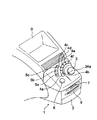
図1は本実施形態例に係る手動入力装置のダッシュボードへの取り付け状態を示す斜視図、図2は本実施形態例に係る手動入力装置が取り付けられた自動車の室内の状態を示す平面図である。
【0016】
図1から明らかなように、本実施形態例に係る手動入力装置1は、筐体2が所要の大きさの角形容器状に形成されており、当該筐体2の上面には、手動操作部3と、当該手動操作部3の設定部を中心とする円弧状に配列された6個の押釦スイッチ4a,4b,4c,4d,4e,4fと、当該6個の押釦スイッチ群の配列位置の外周部分にこれと同心円状に配列された3個の押釦スイッチ5a,5b,5cと、ボリュームつまみ6とが配設されている。また、当該筐体2の前面には、カードスロット7と、ディスクスロット8とが開設されている。この手動入力装置は、図2に示すように、自動車のダッシュボードAの運転席Bと助手席Cとの間に取り付けられ、ダッシュボードAに備えられた表示装置D並びにダッシュボードA内に収納された図示しないコンピュータ(制御部)と共働して、所要の機能を発揮できるようになっている。
【0017】
前出の合計9個の押釦スイッチ4a,4b,4c,4d,4e,4f及び5a,5b,5cは、手動入力装置1を用いて操作しようとする車載電気機器、例えばエアコン、ラジオ、テレビジョン、CDプレーヤ、カーナビゲーションシステムなどと個別に接続される。どの押釦スイッチとどの車載電気機器とを接続するかは任意に設定することができるが、本例の手動入力装置1においては、押釦スイッチ4aがメニュー選択、押釦スイッチ4bが電話、押釦スイッチ4cがエアコン、押釦スイッチ4dがカーナビゲーションシステム、押釦スイッチ4eがラジオ、押釦スイッチ4fがカードのリーダー・ライター又はディスクドライブ装置、押釦スイッチ5aが車載用入力装置1の姿勢制御、押釦スイッチ5bが表示装置Dの全面に設けられた液晶シャッタのオンオフ制御、押釦スイッチ5cがテレビジョンにそれぞれ接続されており、所望の押釦スイッチのノブを押し込むことによって、当該押釦スイッチに接続された車載電気機器を選択できるようになっている。各押釦スイッチのノブの表面には、誤操作を防止するために、各スイッチが接続された各車載電気機器を示す文字や絵文字等が表示される(図示省略)。
【0018】
次に、手動操作部3が備えられる機構部の構成を、図3乃至図5に基づいて説明する。図3は手動操作部を含む機構部の断面図、図4は機構部に備えられるガイド板及びその周辺部分の平面図、図5は機構部に備えられるアクチュエータの主軸とコード板回転軸との連結構造の一例を示す平面図である。
【0019】
図3から明らかなように、機構部11は、略円筒状に形成されたフレーム12と、当該フレーム12の内面に設けられたアクチュエータ受け13と、アクチュエータ14と、当該アクチュエータ14の駆動軸14aに取り付けられたスライダ15と、前記アクチュエータ14を前記アクチュエータ受け13に揺動可能に取り付けるブラケット16と、当該ブラケット16と前記フレーム12との間に設定された第1ばね部材17と、前記アクチュエータ14の上面にボス18を介して取り付けられたプリント基板19と、当該プリント基板19に接続されたスイッチ20及びランプ21と、前記アクチュエータ14の駆動軸14aに取り付けられた手動操作部3と、当該手動操作部3を前記アクチュエータ14に対して常時上向きに付勢する第2ばね部材23と、前記アクチュエータ14の下面に取り付けられたエンコーダ取付板24と、当該エンコーダ取付板24に取り付けられたエンコーダ(第2位置センサ)25と、前記アクチュエータ14の駆動軸14aに取り付けられたプーリー26と、当該プーリー26と前記エンコーダ25の駆動軸とを連結するベルト27と、前記フレーム12の内面に取り付けられ、前記アクチュエータ14の下方に配置されたガイド板28と、前記フレーム12の内面に取り付けられたスティックコントローラ(第1位置センサ)29と、当該スティックコントローラ29と前記アクチュエータ14の駆動軸14aとを連結する連結棒30とから主に構成されている。
【0020】
アクチュエータ受け13は、フレーム12の内面に取り付け可能な直径を有する円筒形の固定部13aと、球面状に形成された受け部13bとから構成されており、球面状の受け部13bを下向きにして、固定部13aがフレーム12の内面にねじ13cで固定される。
【0021】
アクチュエータ14に回転モータを用いた場合には、駆動軸14aを介して手動操作部3に当該駆動軸回りの外力を与えることができる。
【0022】
スライダ15は、前記駆動軸14aの外面に取り付け可能な直径を有する円筒状に形成されており、その一部には、後に詳細に説明する手動操作部3を一体に取り付けるための係合溝15aが形成されている。当該スライダ15は、プリント基板19との間には張設された第2ばね部材23によって常時上向きに付勢されており、当該スライダ15の移動範囲の上端は、駆動軸14aの先端部に螺合されたねじのねじ頭15bによって規制されている。
【0023】
ブラケット16は、アクチュエータ14の外面に取り付け可能な直径を有する円筒形の固定部16aと、当該固定部16aの内面に突設された1個乃至複数個(図3の例では、2個)のスナップ爪16bと、前記受け部13bと略同一曲率の球面状に形成された摺動部16cと、当該摺動部16cより切り起こされたばね受け部16dとから構成されており、固定部16aにアクチュエータ14の下部を強嵌合し、アクチュエータ14の下部外面に形成されたスナップ溝14bにスナップ爪16bを係合することによって、アクチュエータ14に取り付けられる。ブラケット16が取り付けられたアクチュエータ14は、摺動部16cを前記アクチュエータ受け13に載置し、ばね受け部16dとフレーム12に形成されたばね受け部12bとの間に第1ばね部材17を張設することによって、フレーム12に取り付けられる。したがって、アクチュエータ14は、フレーム12に対して任意の方向に揺動することができ、その操作力を除けば、第1ばね部材17の弾性力によって自動的に垂直位置に復帰する。
【0024】
手動操作部3は、手指にて操作可能な大きさのキャップ状に形成された本体部22aと、当該本体部22aの中央部下面より下向きに垂設された略円筒状のスイッチ操作部22bと、当該スイッチ操作部22bの内面に形成された係止爪22cと、前記本体部22aの一部に形成された照光部22dとから構成されており、係止爪22cを前記スライダ15に形成された係合溝15aに係合することによって、スライダ15と一体化される。もちろん、この際には、スイッチ操作部22bの先端部がプリント基板19上に配置されたスイッチ20と対向し、照光部22dがプリント基板19上に配置されたランプ21と対向するように、スライダ15に対する手動操作部3の取付位置が調整される。
【0025】
エンコーダ25は、受発光素子25aと、円板状に形成されたコード板25bと、当該コード板25bを回転可能に支持する回転軸25cと、当該回転軸25cに固着されたプーリー25dとからなる。プーリー25dと前記アクチュエータ14の駆動軸14aに取り付けられたプーリー26との間には、図5に示すようにベルト27が巻き掛けされており、駆動軸14aの回転方向及び回転量に応じた位置信号が受発光素子25aより出力されようになっている。なお、図示は省略するが、前記ベルト27には、張力を一定に保持するためのテンショナーを係合することもできる。
【0026】
ガイド板28は、手動操作部3の操作方向及び操作量を規制するためのものであって、図3に示すように、当該ガイド板28に開設されたガイド溝28aにアクチュエータ14の駆動軸14aを貫通することによって、手動操作部3の操作方向及び操作量を規制するようになっている。図4は、ガイド板28に形成されるガイド溝28aの一例を示す図であって、本例にあっては、ガイド溝28aが、中心位置P1から8方向に延びる放射状に形成されている。なお、図中の符号P2,P3,P4,P5,P6,P7,P8,P9は、各ガイド溝28aの末端部の位置を示している。
【0027】
スティックコントローラ29は、駆動軸14aの揺動方向及び揺動量に応じた位置信号を出力する。前記エンコーダ25から出力される位置信号及び当該スティックコントローラ29から出力される位置信号は、車載された図示しないコンピュータに取り込まれ、前記アクチュエータの制御に供される。
【0028】
連結棒30は、スティックコントローラ29の駆動軸29a及びアクチュエータ14の駆動軸14aと玉継手30a,30b介して連結されており、駆動軸14aの動きを駆動軸29aに伝達する。なお、この連結棒30には摺動ガイド30cが開設されており、当該摺動ガイド30cにはエンコーダ取付板24の先端部24aが挿入されていて、連結棒30の回り止めが図られている。
【0029】
かかる構成において、手動操作部3をガイド板28と平行な方向に操作すると、その操作力がアクチュエータ14を介してブラケット16に伝達され、アクチュエータ受け13の受け部13bとブラケット16の摺動部16cとの間に滑りを生じて、アクチュエータ14が揺動する。このとき、アクチュエータ14の駆動軸14aは、ガイド板28に開設された放射状のガイド溝28aに貫通されているので、アクチュエータ14は、ガイド溝28aの中心位置P1から各切換位置P2〜P9の方向にのみ選択的に揺動される。
【0030】
このようにしてアクチュエータ14が揺動すると、それと一体に駆動軸14aが揺動し、その動きが、連結棒30を介してスティックコントローラ29の駆動軸29aに伝達され、スティックコントローラ29から駆動軸29aの揺動方向及び揺動量に対応する位置信号が出力される。この位置信号は、図示しないコンピュータに取り込まれ、当該コンピュータによって、所望の電気機器の選択が行われる。この状態から、手動操作部3に加えられた操作力を除くと、アクチュエータ14は、フレーム12とブラケット16との間に調節された第1ばね部材17の弾性力によって自動的に垂直位置に復帰する。
【0031】
また、手動操作部3を駆動軸14aの回りに回転操作すると、その回転力が駆動軸14a、プーリー26、ベルト27及びプーリー25dを介してコード板25bに伝達され、手動操作部3の回転方向にコード板25bが回転されて、エンコーダ25の受発光素子25aから手動操作部3の回転方向及び回転量に対応する位置信号が出力される。この位置信号も、図示しないコンピュータに取り込まれ、当該コンピュータによって、先に選択された電気機器の機能調整と、アクチュエータ14の動作制御が行われる。エンコーダ25から出力される位置信号に基づくアクチュエータ14の制御方法についても、後に説明する。
【0032】
さらに、手動操作部3を駆動軸14aの軸方向に押圧すると、手動操作部3及びこれと一体に連結されたスライダ15が第2ばね部材23の弾性力に抗して下降する。そして、手動操作部3に形成されたスイッチ操作部22bがプリント基板19上に配置されたスイッチ20を押圧し、スイッチ20からスイッチ信号が出力される。このスイッチ信号も、図示しないコンピュータに取り込まれ、当該コンピュータによって、選択された電気機器及び機能の確定が行われる。スイッチ押圧後、手動操作部3に加えられた操作力を除くと、手動操作部3は、前記第2ばね部材23の弾性力によって自動的に上端位置に復帰する。
【0033】
以下、エンコーダ25から出力される位置信号に基づくアクチュエータ14の制御方法を、図6乃至図10に基づいて説明する。図6は手動操作部3の操作方向とそれによって選択される車載電気機器の種別を例示する説明図、図7は手動操作部3の回転操作とそれによって調整される機能を例示する説明図、図8はアクチュエータ14の制御システムを示すブロック図、図9は手動操作部3に負荷される外力のモードを例示するグラフ図、図10はアクチュエータ14の制御手順を示すフローチャートである。
【0034】
本例の手動入力装置1は、図6(a),(b)に示すように、手動操作部3をセンタ位置より前、右前、右、右後、後、左後、左、左前の各方向に操作することによって、それぞれラジオ、エアコン、カーナビゲーションシステム、CDプレーヤ、テレビジョン、監視カメラ、電子メール、電話を選択できるようになっている。なお、手動入力装置1に備えられた押釦スイッチ4a,4b,4c,4d,4e,4f及び5a,5b,5cによって選択される電気機器の種別と当該手動操作部3を操作することによって選択される電気機器の種別とは、同種の電気機器の組み合わせとすることもできるし、異種の電気機器の組み合わせとすることもできる。本実施形態例においては、押釦スイッチ4a〜4f及び5a〜5cによって選択される電気機器の種別と手動操作部3を操作することによって選択される電気機器の種別とを、異種の電気機器の組み合わせとしている。
【0035】
また、本例の手動入力装置1は、1の電気機器を選択した後、手動操作部3を操作することによって、当該選択された電気機器の機能を調整できるようになっている。例えば、手動操作部3を操作することによってラジオ局の選局が選択された場合、図7(a)に示すように、手動操作部3を回転操作することによって、所望の放送局の選局が可能になる。また、手動操作部3を操作することによってエアコンの温度調節が選択された場合、図7(b)に示すように、手動操作部3を回転操作することによって、エアコンの設定温度の上昇または下降が可能になる。
【0036】
本実施形態例に係る手動入力装置1は、アクチュエータ14の制御システムが図8に示す構成となっており、図10に示す手順でアクチュエータ14を制御することにより、図9に例示する外力を手動操作部3の操作に応じて手動操作部3に付加できるようになっている。
【0037】
即ち、図8に示すように、本例のアクチュエータ制御システムは、ダッシュボードA内のコンピュータに備えられたCPU41に、照合部42とパターン選択部43とを設けると共に、当該コンピュータに備えられたROM44に、手動操作部3の操作領域と各操作領域に応じたアクチュエータ14の駆動条件(出力値或いは出力モード)を符号化したパターン45a,45b,45c・・・を記憶する。また、前記コンピュータに、スティックコントローラ29からの信号を取り込んで前記テーブル選択部43に手動操作部3の操作領域に応じたパターン選択信号を出力すると共に、表示装置Dに手動操作部3の操作軌跡を表示する位置信号検出部46を備える。
【0038】
図9は、ROM44に記憶されたアクチュエータ14の駆動パターンをグラフ化して例示するものであって、図9(a)は手動操作部3の回転量に拘わらず一定モードの振動を手動操作部に負荷するパターン、図9(b)は手動操作部3の回転量が増加するにしたがって衝撃的な振動を周期的に手動操作部に負荷するパターン、図9(c)は手動操作部3の回転量が増加するにしたがって他のモードの振動を周期的に手動操作部に負荷するパターン、図9(d)は手動操作部3にセンター復帰方向の外力を負荷するパターン、図9(e)は手動操作部3の回転量が予め定められた量になったときに手動操作部に大きな抵抗感を負荷するパターンである。図9(a)のパターンが選択された場合、手動操作部3には回転操作に伴う抵抗感が付与されるので、手動操作部3の微操作が容易になる。図9(b)又は図9(c)のパターンが選択された場合、手動操作部3には周期的なクリック感が付与されるので、例えば図7(a)に示したラジオ局の選局を行う場合、各ラジオ局が同調するごとに手動操作部3に外力が負荷されるようにすることによって、ラジオ局の選局を容易化することができる。また、図9(d)のパターンが選択された場合には、手動操作部3を自動的にセンター位置に復帰させることができるので、例えば図7(b)に示したエアコンの温度調節を容易化することができる。さらに、図9(e)のパターンが選択された場合には、操作者に手動操作部3の操作限界を知得させることができる。
【0039】
以下、コンピュータによるアクチュエータ14の制御手順を、図8を参照しつつ、図10に基づいて説明する。
【0040】
操作者が押釦スイッチ4a〜4f,5a〜5cのいずれかを押圧すると、押圧された押釦スイッチよりスイッチ信号が出力され、当該スイッチ信号に対応する電気機器が選択される(手順S1)。位置信号検出部46は、押圧された押釦スイッチより出力されたスイッチ信号を取り込み、選択された電気機器を表示画面Dに表示する(手順S2)。この状態から操作者が手動操作部3を揺動操作すると(手順S3)、スティックコントローラ29から手動操作部3の揺動量及び揺動方向に応じた信号が出力される(手順S4)。照合部42は、スティックコントローラ29からの出力信号を照合用基準値と照合し、手動操作部3の揺動操作位置を確定する(手順S5)。位置信号検出部46は、スティックコントローラ29からの出力信号を取り込んで、手動操作部3の揺動操作位置に応じた電気機器の機能を選択し、当該選択された機能を表示画面Dに表示すると共に、パターン選択部43にパターン選択信号を出力する(手順S6)。パターン選択部43は、パターン選択信号を取り込み、ROM44に記憶された複数のパターン45a,45b,45c・・・の中からパターン選択信号に対応するパターンを選択する(手順S7)。この状態から操作者が手動操作部3を回転操作すると(手順S8)、エンコーダ25から手動操作部3の回転量及び回転方向に応じた信号が出力される(手順S9)。照合部42は、エンコーダ25からの出力信号を照合用基準値と照合し、手動操作部3の回転操作位置を確定する(手順S10)。位置信号検出部46は、エンコーダ25からの出力信号を取り込んで、機能の調整状態を表示画面Dに表示する(手順S11)。照合部42は、手順S7で選択されたパターンと手順S10で確定された手動操作部3の回転操作位置とから、アクチュエータ14の出力値を確定する(手順S12)。次いで、ドライバ47から手順S12で確定された出力値を出力して、アクチュエータ14を駆動する(手順S13)。これによって、手動操作部3がアクチュエータ14によって駆動され、手動操作部3を介してアクチュエータ14からの外力が操作者に伝達される(手順S14)。以下、S1乃至S14の手順を繰り返す。
【0041】
かように、本例の手動入力装置1は、手動操作部3の回転操作に伴って手動操作部3に所定の外力を負荷するので、操作者は手動操作部3の操作内容をブラインドタッチで知ることができ、手動操作部3の操作性を良好なものにすることができる。
【0042】
また、手動操作部3を駆動軸14aの周りに回転することによって、選択された機能の調整を行うことができる。即ち、手動操作部3を駆動軸14aの周りに回転すると、その回転力が駆動軸14a、プーリー26、ベルト27及びプーリー25dを介してコード板25bに伝達され、手動操作部3の回転方向にコード板25bが回転されて、エンコーダ25の受発光素子25aから手動操作部3の回転方向及び回転量に対応する位置信号が出力されるので、この位置信号をコンピュータに取り込むことによって、図10の手順に従って、所要の機能調整を行うことができる。
【0043】
例えば、手動操作部3を操作してエアコンの設定温度を変更しようとする場合、手動操作部3の操作量(回転量)が小さい場合には、設定温度の切換が緩やかに行われるが、手動操作部3の操作量(回転量)を大きくすると、設定温度の切換が高速で行われる。このため、手動操作部3の操作に何ら抵抗感がないと、手動操作部3の操作量(回転量)が大きくなりやすく、設定温度の小さな変更を正確かつ迅速に行うことが難しくなって、操作性が悪いものになる。そこで、手動操作部3の操作量(回転量)がある程度大きくなったとき、アクチュエータ14を駆動して手動操作部3に抵抗感を負荷する。これによって、ユーザは、手動操作部3の操作量(回転量)が大きすぎてエアコンの設定温度を微調整できないことを感覚的に知ることができるので、手動操作部3の操作量(回転量)を小さくすることによって、エアコンの設定温度の微調整を正確かつ迅速に行うことができる。なお、手動操作部3の操作量(回転量)がある程度大きくなった段階で手動操作部3の操作に抵抗感を付与する構成に代えて、手動操作部3の操作量(回転量)に応じて、異なる抵抗感を手動操作部3に順次付与するように構成することもできる。また、上記の説明では、手動操作部3の操作量(回転量)を増加するにしたがって、例えばエアコンの設定温度などの調整速度が上がる場合を例にとって説明したが、手動操作部3の操作速度が増加するにしたがって調整速度が上がる場合にも、同様の方法によって手動操作部3に抵抗感を付与することもできる。
【0044】
また、押釦スイッチ5aを操作して車載用入力装置1の姿勢制御、例えばハンドルの高さ調整を選択した場合において、現在のハンドル高さからハンドルの可動端までの可動範囲に関係なく、同じ抵抗感で手動操作部3が操作できるようになっていると、ユーザが車載電気機器の可動範囲を把握することができないために、現在のハンドルの設定高さから調整しようとする方向の可動端までの可動範囲が大きく、手動操作部3の操作量(回転量)を大きくして迅速にハンドル高さを目標高さまで移動できる場合や、これとは反対に、可動範囲が小さく、手動操作部3の操作量(回転量)を小さくしてハンドルがその可動端に衝突しないようにしなくてはならない場合にも、このような適切な操作を行うことができず、ハンドルの高さ調整に長時間を要したり、ハンドルが可動端に高速で衝突して衝撃が発生するといった不都合を起こしやすい。そこで、車載されたコンピュータにてハンドルの可動範囲を算出し、可動範囲の大小に応じた抵抗感をアクチュエータ14にて手動操作部3に負荷するようにすれば、ユーザは手動操作部3の操作時にハンドルの可動範囲を感得することができるので、可動範囲に応じた適切な手動操作部3の操作を行うことができ、前記の不都合を解消することができる。なお、可動範囲の算出は、車載用入力装置1の姿勢制御を行うためのアクチュエータにエンコーダ等の位置センサを付設し、当該位置センサから出力される位置信号をコンピュータに取り込むことによって行うことができる。
【0045】
さらに、手動入力装置1のユーザには、力が強い者も力が弱い者もいる。したがって、手動操作部3の操作力(抵抗感)を一定にすると、力が強いユーザにとっては、手動操作部3の操作が軽すぎて車載用入力装置1の微調整が難しく、反対に力が弱いユーザにとっては、手動操作部3の操作が重すぎて車載用入力装置1の大調整が難しい場合を生じる。そこで、車載されたコンピュータにて手動操作部3に加えられた操作力を算出し、操作力の大小に応じた抵抗感をアクチュエータ14にて手動操作部3に負荷するようにすれば、個々のユーザに最適な抵抗感を付与することができるので、力が強いユーザにも、力が弱いユーザにも良好な操作感を与えることができる。なお、手動操作部3に加えられた操作力の算出は、エンコーダ25から出力される位置信号をコンピュータに取り込み、位置信号の変化の加速度を演算することによって行うことができる。
【0046】
加えて、手動操作部3に抵抗感を与えるだけでなく、手動操作部3を動かす向きに外力を加えることも可能である。例えば、後述するラジオやCDプレーヤの音量を調節する場合、音量をアップする方向に手動操作部3を動かすときには抵抗感を感じるように、反対に、音量をダウンする方向に手動操作部3を動かすときには加速感を感じるように手動操作部3に外力を負荷することができる。このようにすると、音量をアップする際に車室内に出る音が急に大きくなるといった不都合を解消できると共に、音量をダウンしたいときには速やかに音量を絞れるので、オーディオの聴取や会話が妨げられるといった不都合を解消できる。
【0047】
これらの各制御も、コンピュータに備えられたROM44に、図9及び図10に例示するような所要のパターンデータを予め記憶しておくことによって行うことができる。
【0048】
その他、各電気機器の各操作内容に関して、アクチュエータ14の出力値が異なる複数のパターンを予めコンピュータに記憶しておき、ユーザの好みに応じて、適宜アクチュエータ14の制御に使用するパターンを切り換えられるようにすることもできる。パターンの切替は、例えば手動操作部又はその近傍部分にパターン切替用のスイッチ(図示省略)を備え、ユーザが適宜当該スイッチを操作することによって行うことができる。また、コンピュータが個々のユーザのIDを認識し、自動的にパターンを切り換えるようにすることもできる。このようにすると、ユーザの好みに応じて手動操作部に作用する抵抗感を適宜切り替えることができるので、手動操作部の操作性をより良好なものにすることができる。
【0049】
【発明の効果】
本発明によれば、アクチュエータをフレームに揺動自在に取り付け、当該アクチュエータの揺動方向及び揺動量を第1位置センサにて検出すると共に、当該アクチュエータの駆動軸の回転方向及び回転量を第2位置センサにて検出するので、例えばアクチュエータの揺動方向を切り換えることによって機能調整しようとする車載電気機器の選択を行い、駆動軸の回転量に応じて選択された車載電気機器の機能調整を行うようにすることによって、1つの手動操作部にて所望の車載電気機器の選択と機能調整とを行うことができる。また、手動操作部をアクチュエータの駆動軸に取り付け、手動操作部にその操作内容に応じた外力を負荷するようにしたので、ユーザに手動操作部の操作内容をブラインドタッチで告知することができ、ユーザは、手動操作部が所望の方向に所望の操作量だけ所望の速度で操作されているか否かを感覚的に知ることができるので、手動操作部の誤操作が防止され、手動入力装置の操作性を良好なものにすることができる。また、手動操作部をアクチュエータの駆動軸に取り付けたので、手動操作部と駆動軸とをつなぐ動力伝達機構が不要となり、手動入力装置の小型化及び軽量化を図ることができる。さらに、アクチュエータを1つだけ備えるので、この点からも手動入力装置の小型化及び軽量化を図ることができる。
【図面の簡単な説明】
【図1】実施形態例に係る車載用入力装置のダッシュボードへの取り付け状態を示す斜視図である。
【図2】実施形態例に係る車載用入力装置が取り付けられた自動車の室内の状態を示す平面図である。
【図3】手動操作部を含む機構部の断面図である。
【図4】機構部に備えられるガイド板及びその周辺部分の平面図である。
【図5】機構部に備えられるアクチュエータの主軸とコード板回転軸との連結構造の一例を示す平面図である。
【図6】実施形態例に係る手動操作部の操作方向とそれによって選択される車載電気機器の種別を例示する説明図である。
【図7】実施形態例に係る手動操作部の操作方向とそれによって切り換えられる機能の種別を例示する説明図である。
【図8】実施形態例に係るアクチュエータの制御システムを示すブロック図である。
【図9】実施形態例に係る手動操作部に負荷される外力のパターンを例示するグラフ図である。
【図10】実施形態例に係るアクチュエータの制御手順を示すフローチャートである。
【図11】従来例に係る車載用入力装置の設置例を示す自動車の内面図である。
【図12】従来提案されている車載用入力装置の側面図である。
【図13】図12に示す車載用入力装置の手動操作部の平面図である。
【図14】図12に示す車載用入力装置に組み込まれているガイドプレートの平面図である。
【符号の説明】
1 車載用入力装置
2 筐体
3 手動操作部
4a,4b,4c,4d,4e,4f 押釦スイッチ
5a,5b,5c 押釦スイッチ
6 ボリュームつまみ
7 カードスロット
8 ディスクスロット
11 機構部
14 アクチュエータ
14a 駆動軸
25 エンコーダ(第2位置センサ)
29 スティックコントローラ(第1位置センサ)
41 CPU
42 照合部
43 テーブル選択部
44 ROM
45a,45b,45c テーブル
46 位置信号検出部[0001]
BACKGROUND OF THE INVENTION
The present invention relates to a manual input device that intensively operates various electronic devices mounted on a vehicle, for example, with a single manual operation unit, and in particular, a manual input device in which an actuator that applies an external force to the manual operation unit is made into one motor. About.
[0002]
[Prior art]
In recent years, automobiles are equipped with various electronic devices such as air conditioners, radios, televisions, CD players, navigation systems, and the like. Attempting to do so may interfere with the driving of the car. Therefore, in order to facilitate the on / off switching and function selection of a desired electronic device without hindering safe driving, various types of electronic devices have been conventionally operated by operating one manual operation unit. Manual input devices that can be operated have been proposed.
[0003]
The prior art of such a manual input device will be described with reference to FIGS. FIG. 11 is an inner surface view of an automobile showing an installation example of a manual input device, FIG. 12 is a side view of a conventionally proposed manual input device, and FIG. 13 is a plan view of a manual operation unit of the manual input device shown in FIG. 14 is a plan view of a guide plate incorporated in the manual input device shown in FIG.
[0004]
As shown in FIG. 11, the
[0005]
The
[0006]
As shown in FIG. 11, the
[0007]
Function selection and function adjustment of the electronic device selected by the
[0008]
Then, after selecting these functions, the functions can be adjusted by appropriately operating the
[0009]
[Problems to be solved by the invention]
However, the
[0010]
The present invention has been made in order to eliminate the deficiencies of the prior art, and the object of the present invention is to reduce the size of the vehicle-mounted input device with excellent operability that can reliably perform a desired operation. Is to provide.
[0011]
[Means for Solving the Problems]
In order to solve the above problems, the present invention provides a manual input device as a frame. Through the bracket An actuator that is swingably mounted, a manual operation unit that is mounted on a drive shaft of the actuator, a first position sensor that detects a swing direction and a swing amount of the actuator, and a rotation direction of the drive shaft of the actuator And a second position sensor for detecting the amount of rotation, and each position signal output from the first and second position sensors to control the actuator, and load an external force corresponding to the operation on the manual operation unit. And a control unit to be configured.
[0012]
A rotary motor can be used as the actuator. In this case, an external force that vibrates around the drive shaft of the rotary motor can be applied to the manual operation unit.
[0013]
According to this configuration, the actuator is swingably attached to the frame, the swing direction and the swing amount of the actuator are detected by the first position sensor, and the rotation direction and the rotation amount of the drive shaft of the actuator are detected at the second position. Since it is detected by the sensor, for example, the on-vehicle electric device whose function is to be adjusted is selected by switching the swing direction of the actuator, and the function of the on-vehicle electric device selected according to the amount of rotation of the drive shaft is adjusted. By doing so, it is possible to perform selection and function adjustment of a desired in-vehicle electric device with one manual operation unit. In addition, since the manual operation unit is attached to the drive shaft of the actuator and an external force corresponding to the operation is loaded on the manual operation unit, the operation content of the manual operation unit can be notified to the user by blind touch. Can sensuously know whether or not the manual operation unit is operated in a desired direction at a desired speed by a desired operation amount, so that an erroneous operation of the manual operation unit is prevented and the operability of the manual input device is improved. Can be improved. Further, according to this configuration, since the manual operation unit is attached to the drive shaft of the actuator, a power transmission mechanism that connects the manual operation unit and the drive shaft becomes unnecessary, and the manual input device can be reduced in size and weight. it can. Furthermore, according to this configuration, since only one actuator is provided, the manual input device can be reduced in size and weight from this point.
[0014]
DETAILED DESCRIPTION OF THE INVENTION
Hereinafter, an embodiment of a manual input device according to the present invention will be described with reference to the drawings.
[0015]
FIG. 1 is a perspective view showing a state in which a manual input device according to the present embodiment is attached to a dashboard, and FIG. 2 is a plan view showing a state of the interior of the automobile to which the manual input device according to the present embodiment is attached. is there.
[0016]
As is clear from FIG. 1, in the
[0017]
A total of nine
[0018]
Next, the structure of the mechanism part in which the
[0019]
As is apparent from FIG. 3, the
[0020]
The
[0021]
When a rotary motor is used for the
[0022]
The
[0023]
The
[0024]
The
[0025]
The
[0026]
The
[0027]
The
[0028]
The connecting
[0029]
In this configuration, when the
[0030]
When the
[0031]
When the
[0032]
Further, when the
[0033]
Hereinafter, a method for controlling the
[0034]
As shown in FIGS. 6 (a) and 6 (b), the
[0035]
Further, the
[0036]
In the
[0037]
That is, as shown in FIG. 8, in the actuator control system of this example, the CPU 41 provided in the computer in the dashboard A is provided with the
[0038]
FIG. 9 is a graph illustrating the drive pattern of the
[0039]
Hereinafter, the control procedure of the
[0040]
When the operator presses any one of the
[0041]
Thus, since the
[0042]
Further, the selected function can be adjusted by rotating the
[0043]
For example, when the
[0044]
Further, when the
[0045]
Furthermore, some users of the
[0046]
In addition, it is possible not only to give resistance to the
[0047]
Each of these controls can also be performed by preliminarily storing necessary pattern data as exemplified in FIGS. 9 and 10 in a
[0048]
In addition, a plurality of patterns with different output values of the
[0049]
【The invention's effect】
According to the present invention, the actuator is swingably attached to the frame, the swing direction and the swing amount of the actuator are detected by the first position sensor, and the rotation direction and the rotation amount of the drive shaft of the actuator are second. Since it is detected by the position sensor, for example, the on-vehicle electric device whose function is to be adjusted is selected by switching the swing direction of the actuator, and the function adjustment of the on-vehicle electric device selected according to the amount of rotation of the drive shaft is performed. By doing so, it is possible to perform selection and function adjustment of a desired in-vehicle electric device with one manual operation unit. In addition, since the manual operation unit is attached to the drive shaft of the actuator and external force corresponding to the operation content is loaded on the manual operation unit, the operation content of the manual operation unit can be notified to the user by blind touch, Since the user can sensuously know whether or not the manual operation unit is operated in a desired direction by a desired operation amount at a desired speed, erroneous operation of the manual operation unit is prevented, and the manual input device is operated. The property can be improved. Further, since the manual operation unit is attached to the drive shaft of the actuator, a power transmission mechanism that connects the manual operation unit and the drive shaft becomes unnecessary, and the manual input device can be reduced in size and weight. Furthermore, since only one actuator is provided, the manual input device can be reduced in size and weight from this point.
[Brief description of the drawings]
FIG. 1 is a perspective view showing a state in which an in-vehicle input device according to an embodiment is attached to a dashboard.
FIG. 2 is a plan view showing a state of the interior of the automobile to which the in-vehicle input device according to the embodiment is attached.
FIG. 3 is a cross-sectional view of a mechanism unit including a manual operation unit.
FIG. 4 is a plan view of a guide plate provided in a mechanism unit and its peripheral portion.
FIG. 5 is a plan view showing an example of a connection structure between a main shaft of an actuator provided in a mechanism unit and a code plate rotation shaft.
FIG. 6 is an explanatory diagram illustrating the operation direction of the manual operation unit according to the embodiment and the type of in-vehicle electric device selected by the operation direction.
FIG. 7 is an explanatory diagram illustrating the operation direction of the manual operation unit according to the embodiment and the types of functions switched by the operation direction;
FIG. 8 is a block diagram illustrating an actuator control system according to an embodiment.
FIG. 9 is a graph illustrating a pattern of external force applied to the manual operation unit according to the embodiment.
FIG. 10 is a flowchart showing a control procedure of the actuator according to the embodiment.
FIG. 11 is an inner surface view of an automobile showing an installation example of an in-vehicle input device according to a conventional example.
FIG. 12 is a side view of a conventionally proposed in-vehicle input device.
13 is a plan view of a manual operation unit of the in-vehicle input device shown in FIG.
14 is a plan view of a guide plate incorporated in the in-vehicle input device shown in FIG.
[Explanation of symbols]
1 In-vehicle input device
2 Case
3 Manual operation unit
4a, 4b, 4c, 4d, 4e, 4f Pushbutton switch
5a, 5b, 5c Pushbutton switch
6 Volume knob
7 Card slot
8 disk slots
11 Mechanism
14 Actuator
14a Drive shaft
25 Encoder (second position sensor)
29 Stick controller (first position sensor)
41 CPU
42 Verification part
43 Table selection section
44 ROM
45a, 45b, 45c Table
46 Position signal detector
Claims (2)
Priority Applications (4)
| Application Number | Priority Date | Filing Date | Title |
|---|---|---|---|
| JP2000343987A JP3920559B2 (en) | 2000-11-10 | 2000-11-10 | Manual input device |
| US09/992,405 US20020057064A1 (en) | 2000-11-10 | 2001-11-06 | Manual input device using a motor as an actuator for applying an external force to its manual control knob |
| EP01126399A EP1205956B1 (en) | 2000-11-10 | 2001-11-07 | Manual input device using a motor as an actuator for applying an external force to its manual control knob |
| DE60122453T DE60122453T2 (en) | 2000-11-10 | 2001-11-07 | Manual input device which uses a motor to generate an external force on its manual control knob |
Applications Claiming Priority (1)
| Application Number | Priority Date | Filing Date | Title |
|---|---|---|---|
| JP2000343987A JP3920559B2 (en) | 2000-11-10 | 2000-11-10 | Manual input device |
Publications (2)
| Publication Number | Publication Date |
|---|---|
| JP2002149324A JP2002149324A (en) | 2002-05-24 |
| JP3920559B2 true JP3920559B2 (en) | 2007-05-30 |
Family
ID=18818262
Family Applications (1)
| Application Number | Title | Priority Date | Filing Date |
|---|---|---|---|
| JP2000343987A Expired - Fee Related JP3920559B2 (en) | 2000-11-10 | 2000-11-10 | Manual input device |
Country Status (4)
| Country | Link |
|---|---|
| US (1) | US20020057064A1 (en) |
| EP (1) | EP1205956B1 (en) |
| JP (1) | JP3920559B2 (en) |
| DE (1) | DE60122453T2 (en) |
Families Citing this family (35)
| Publication number | Priority date | Publication date | Assignee | Title |
|---|---|---|---|---|
| JP2004139845A (en) * | 2002-10-17 | 2004-05-13 | Alps Electric Co Ltd | Inner force sense applying type input device |
| JP4057900B2 (en) | 2002-12-09 | 2008-03-05 | アルプス電気株式会社 | Haptic input device |
| JP4268430B2 (en) | 2003-03-19 | 2009-05-27 | アルプス電気株式会社 | Haptic input device |
| JP4209235B2 (en) * | 2003-03-28 | 2009-01-14 | アルプス電気株式会社 | Haptic input device |
| JP2004359103A (en) * | 2003-06-04 | 2004-12-24 | Alps Electric Co Ltd | On-vehicle electrical equipment control device |
| JP2005030451A (en) | 2003-07-08 | 2005-02-03 | Alps Electric Co Ltd | Kinesthetic sense application type input device |
| JP4148084B2 (en) * | 2003-09-25 | 2008-09-10 | 株式会社デンソー | Display operation system |
| JP2005332157A (en) * | 2004-05-19 | 2005-12-02 | Alps Electric Co Ltd | Haptic force application type input device |
| JP2005332156A (en) * | 2004-05-19 | 2005-12-02 | Alps Electric Co Ltd | Force sense giving type input device |
| JP4327661B2 (en) | 2004-06-07 | 2009-09-09 | アルプス電気株式会社 | Haptic input device |
| ATE442660T1 (en) | 2004-07-22 | 2009-09-15 | Harman Becker Automotive Sys | OPERATING DEVICE AND VEHICLE MULTIMEDIA DEVICE |
| DE102005035526A1 (en) * | 2004-07-28 | 2006-03-23 | Marquardt Gmbh | Compact joystick switch unit, used for inputting data into diverse electronic units of vehicle, has operating knob swung on pivot in one or more preferred directions |
| JP4262661B2 (en) | 2004-09-30 | 2009-05-13 | アルプス電気株式会社 | Haptic input device |
| DE102005021125B3 (en) * | 2005-05-06 | 2006-11-30 | Daimlerchrysler Ag | Taximeters for taxi vehicles and / or rental vehicles |
| JP4826357B2 (en) * | 2005-07-27 | 2011-11-30 | 株式会社デンソー | Manual operation device |
| US20070063995A1 (en) * | 2005-09-22 | 2007-03-22 | Bailey Eric A | Graphical user interface for use with a multi-media system |
| US7920075B2 (en) * | 2006-12-21 | 2011-04-05 | Dexin Corporation | Regulation control device with an encoder and its encoder mechanism |
| JP4769757B2 (en) * | 2007-04-11 | 2011-09-07 | アルプス電気株式会社 | Manual input device |
| DE102007039318A1 (en) * | 2007-08-20 | 2009-02-26 | Daimler Ag | Rotary switch with haptic marking |
| JP5253044B2 (en) * | 2008-08-29 | 2013-07-31 | キヤノン株式会社 | Motor with encoder and positioning device |
| CH699586B1 (en) * | 2008-09-16 | 2011-11-15 | Johnson Electric Switzerland Ag | Device for a joystick. |
| JP5170683B2 (en) * | 2008-11-04 | 2013-03-27 | 株式会社デンソー | In-vehicle remote control device |
| JP5610504B2 (en) * | 2009-04-22 | 2014-10-22 | 株式会社プロテックデザイン | Rotary input device and electronic device |
| JP5662652B2 (en) * | 2009-05-11 | 2015-02-04 | 株式会社プロテックデザイン | Touch imparting device and electronic device |
| JP2010286221A (en) * | 2009-06-15 | 2010-12-24 | Sharp Corp | Heating cooker |
| WO2011062910A1 (en) * | 2009-11-17 | 2011-05-26 | Immersion Corporation | Systems and methods for a friction rotary device for haptic feedback |
| CA152971S (en) * | 2013-04-11 | 2014-12-01 | Samsung Electronics Co Ltd | Washing machine |
| KR102245101B1 (en) * | 2014-11-13 | 2021-04-27 | 삼성디스플레이 주식회사 | Display device |
| EP3130978B1 (en) * | 2015-08-11 | 2019-07-10 | W. Gessmann GmbH | Operating device with electromechanical haptic locking function |
| CN110832437A (en) * | 2017-07-05 | 2020-02-21 | 三菱电机株式会社 | Operation unit control device and operation unit control method |
| DE102017011682A1 (en) * | 2017-12-18 | 2019-06-19 | Drägerwerk AG & Co. KGaA | Method for operating a medical device and medical device operating according to the method |
| WO2019142425A1 (en) * | 2018-01-19 | 2019-07-25 | パナソニックIpマネジメント株式会社 | Input system and switch |
| KR102659241B1 (en) * | 2019-03-08 | 2024-04-18 | 현대자동차주식회사 | Shift lever of dial type |
| JP2021197021A (en) * | 2020-06-17 | 2021-12-27 | 株式会社東海理化電機製作所 | Instruction input device, controller, and computer program |
| DE102020120603A1 (en) | 2020-08-05 | 2022-02-10 | Miele & Cie. Kg | Operating device and method for operating a system |
Family Cites Families (27)
| Publication number | Priority date | Publication date | Assignee | Title |
|---|---|---|---|---|
| JPS6253540U (en) * | 1985-09-24 | 1987-04-02 | ||
| US5191971A (en) * | 1991-04-05 | 1993-03-09 | Lutron Electronics Co., Inc. | Multi-position wall mountable control switch with tactile feedback linear actuator |
| DE4205875A1 (en) * | 1992-02-26 | 1993-09-02 | Vdo Schindling | Rotary selector e.g. for manual input of data in to electronic equipment - has movement of rotary input knob controlled by motor and generator with positions defined by load data in memory |
| JPH05276579A (en) * | 1992-03-26 | 1993-10-22 | Alpine Electron Inc | Remote controller for on-vehicle equipment |
| US6437771B1 (en) * | 1995-01-18 | 2002-08-20 | Immersion Corporation | Force feedback device including flexure member between actuator and user object |
| US5931739A (en) * | 1993-12-27 | 1999-08-03 | Moog Inc. | Fail-safe ride simulator |
| WO1995020787A1 (en) * | 1994-01-27 | 1995-08-03 | Exos, Inc. | Multimode feedback display technology |
| US6004134A (en) * | 1994-05-19 | 1999-12-21 | Exos, Inc. | Interactive simulation including force feedback |
| DE19528457C2 (en) * | 1995-08-03 | 2001-03-08 | Mannesmann Vdo Ag | Control device |
| US5999168A (en) * | 1995-09-27 | 1999-12-07 | Immersion Corporation | Haptic accelerator for force feedback computer peripherals |
| US6154201A (en) * | 1996-11-26 | 2000-11-28 | Immersion Corporation | Control knob with multiple degrees of freedom and force feedback |
| JP3744643B2 (en) * | 1997-03-27 | 2006-02-15 | アルプス電気株式会社 | Multi-directional input device |
| DE19732287A1 (en) * | 1997-07-26 | 1999-01-28 | Bayerische Motoren Werke Ag | Multifunction control device |
| US6104382A (en) * | 1997-10-31 | 2000-08-15 | Immersion Corporation | Force feedback transmission mechanisms |
| DE19752056C5 (en) * | 1997-11-25 | 2010-06-02 | Bayerische Motoren Werke Aktiengesellschaft | Device for controlling a screen display |
| DE19843421B4 (en) * | 1997-11-25 | 2007-07-05 | Bayerische Motoren Werke Ag | Device for selecting points of a menu structure consisting of menus and / or submenus and / or functions and / or function values |
| JP3790365B2 (en) * | 1998-05-25 | 2006-06-28 | アルプス電気株式会社 | In-vehicle input device |
| JP3717306B2 (en) * | 1998-05-25 | 2005-11-16 | アルプス電気株式会社 | In-vehicle input device |
| US7038667B1 (en) * | 1998-10-26 | 2006-05-02 | Immersion Corporation | Mechanisms for control knobs and other interface devices |
| JP2000149721A (en) * | 1998-11-09 | 2000-05-30 | Alpine Electronics Inc | Operation device for on-vehicle apparatus |
| JP3790372B2 (en) * | 1998-11-13 | 2006-06-28 | アルプス電気株式会社 | Input device |
| DE19856722A1 (en) * | 1998-12-09 | 2000-06-15 | Mannesmann Vdo Ag | Operating device with a handle with at least two degrees of freedom of adjustment |
| EP1021074B1 (en) * | 1999-01-15 | 2012-06-20 | The Boeing Company | Solid state flight deck panels and components thereof |
| US6404417B1 (en) * | 1999-03-22 | 2002-06-11 | Logitech Europe S.A. | Direct drive rotational sensor adapted to withstand off-axis loading |
| DE20014425U1 (en) * | 1999-08-18 | 2001-01-04 | Immersion Corp | Mechanisms for control buttons and other interface devices |
| JP3948189B2 (en) * | 2000-03-28 | 2007-07-25 | 松下電器産業株式会社 | Robot teaching device |
| US7215786B2 (en) * | 2000-06-09 | 2007-05-08 | Japan Science And Technology Agency | Robot acoustic device and robot acoustic system |
-
2000
- 2000-11-10 JP JP2000343987A patent/JP3920559B2/en not_active Expired - Fee Related
-
2001
- 2001-11-06 US US09/992,405 patent/US20020057064A1/en not_active Abandoned
- 2001-11-07 EP EP01126399A patent/EP1205956B1/en not_active Expired - Lifetime
- 2001-11-07 DE DE60122453T patent/DE60122453T2/en not_active Expired - Lifetime
Also Published As
| Publication number | Publication date |
|---|---|
| DE60122453D1 (en) | 2006-10-05 |
| DE60122453T2 (en) | 2007-05-03 |
| EP1205956A3 (en) | 2003-03-26 |
| EP1205956B1 (en) | 2006-08-23 |
| US20020057064A1 (en) | 2002-05-16 |
| EP1205956A2 (en) | 2002-05-15 |
| JP2002149324A (en) | 2002-05-24 |
Similar Documents
| Publication | Publication Date | Title |
|---|---|---|
| JP3920559B2 (en) | Manual input device | |
| JP3850619B2 (en) | In-vehicle input device | |
| JP2002062944A (en) | On-vehicle input device | |
| EP1569073B1 (en) | Single knob multifunction controller and display unit | |
| US6903652B2 (en) | Input apparatus for vehicle-installed instruments | |
| US6805020B2 (en) | Manual input device enabling control of various electric apparatus with single knob | |
| US20060155441A1 (en) | Vehicle information system with steering wheel controller | |
| EP1880903A1 (en) | Electronic apparatus | |
| JP2002347538A (en) | Control device for on-vehicle apparatus | |
| US20020140687A1 (en) | In-vehicle display apparatus | |
| US6366442B1 (en) | Vehicular input device including single manual operating unit for operating various electronic devices mounted on vehicle | |
| JP2001283683A (en) | Input device on vehicle | |
| EP1522462B1 (en) | Input device for multifunctional vehicle equipment | |
| US7086292B2 (en) | Force-feedback input device | |
| US6459169B1 (en) | Vehicular input device capable of being adjusted to conform to the physical constitution of the operator | |
| US20040159163A1 (en) | Sense of force imparting type input device | |
| EP1411410A1 (en) | Sense of force imparting type input device | |
| JP3790372B2 (en) | Input device | |
| JP2001028222A (en) | On-vehicle input device | |
| JP4651216B2 (en) | In-vehicle operation device | |
| JPH10177832A (en) | Switch device for vehicle |
Legal Events
| Date | Code | Title | Description |
|---|---|---|---|
| A977 | Report on retrieval |
Free format text: JAPANESE INTERMEDIATE CODE: A971007 Effective date: 20060426 |
|
| A131 | Notification of reasons for refusal |
Free format text: JAPANESE INTERMEDIATE CODE: A131 Effective date: 20060509 |
|
| A521 | Request for written amendment filed |
Free format text: JAPANESE INTERMEDIATE CODE: A523 Effective date: 20060626 |
|
| TRDD | Decision of grant or rejection written | ||
| A01 | Written decision to grant a patent or to grant a registration (utility model) |
Free format text: JAPANESE INTERMEDIATE CODE: A01 Effective date: 20070206 |
|
| A61 | First payment of annual fees (during grant procedure) |
Free format text: JAPANESE INTERMEDIATE CODE: A61 Effective date: 20070215 |
|
| R150 | Certificate of patent or registration of utility model |
Free format text: JAPANESE INTERMEDIATE CODE: R150 |
|
| FPAY | Renewal fee payment (event date is renewal date of database) |
Free format text: PAYMENT UNTIL: 20100223 Year of fee payment: 3 |
|
| FPAY | Renewal fee payment (event date is renewal date of database) |
Free format text: PAYMENT UNTIL: 20110223 Year of fee payment: 4 |
|
| FPAY | Renewal fee payment (event date is renewal date of database) |
Free format text: PAYMENT UNTIL: 20120223 Year of fee payment: 5 |
|
| FPAY | Renewal fee payment (event date is renewal date of database) |
Free format text: PAYMENT UNTIL: 20120223 Year of fee payment: 5 |
|
| FPAY | Renewal fee payment (event date is renewal date of database) |
Free format text: PAYMENT UNTIL: 20130223 Year of fee payment: 6 |
|
| LAPS | Cancellation because of no payment of annual fees |