JP3877507B2 - Medical device communication system - Google Patents
Medical device communication system Download PDFInfo
- Publication number
- JP3877507B2 JP3877507B2 JP2000261540A JP2000261540A JP3877507B2 JP 3877507 B2 JP3877507 B2 JP 3877507B2 JP 2000261540 A JP2000261540 A JP 2000261540A JP 2000261540 A JP2000261540 A JP 2000261540A JP 3877507 B2 JP3877507 B2 JP 3877507B2
- Authority
- JP
- Japan
- Prior art keywords
- display
- medical
- information
- communication
- biological information
- Prior art date
- Legal status (The legal status is an assumption and is not a legal conclusion. Google has not performed a legal analysis and makes no representation as to the accuracy of the status listed.)
- Expired - Fee Related
Links
Images


Landscapes
- Medical Treatment And Welfare Office Work (AREA)
- Measuring And Recording Apparatus For Diagnosis (AREA)
Description
【0001】
【発明の属する技術分野】
本発明は、外科手術中に測定した患者生体情報を手術システムおよび医局用端末に提供する医療機器通信システムに関する。
【0002】
【従来の技術】
複数の手術用の機器とこれら手術機器を一括制御するシステムコントローラとを備えた手術システムの一つとして内視鏡手術システムがある。一般的な内視鏡手術システムは、観察を行なうための内視鏡、この内視鏡に接続されるカメラへッド、前記内視鏡を通して観察部位ヘ照明光を供給する光源装置、前記カメラへッドで撮影した画像信号を処理する内視鏡カメラ装置、この内視鏡カメラ装置で処理された観察部位の被写体映像を表示するモニター、腹腔内を拡張させるための気腹装置、手技を行なうための手術装置であり生体組織を切除あるいは凝固する高周波焼灼装置等複数の医療機器で構成されている。これらの手術装置は主に外科医が操作し、使用するものである。
【0003】
一方、手術室には患者モニター装置と呼ばれる、主に麻酔医が監視している装置がある。これは、患者の生体情報(以下バイタルサインとも称する)を集中的に監視できるようにしたもので、心電計、パルスオキシメーター、カプノメーター等が接続され、心電図、呼気炭酸ガス濃度、血圧、血中酸素飽和度等のバイタルサインを測定し、集中表示が可能なものである。
【0004】
また、各手術室の患者モニターと、CCU、病室に設置された患者モニターを通信手段により接続し、医局やナースステーションで監視やデータの記録を行なう院内システムが提供されている。
【0005】
特開平7−303654号公報においては、複数の手術装置を容易に操作、制御し、システムとしての操作性を向上させるため、被制御装置の機能を表示する手段と、被制御装置を操作する手段とを設けたシステム制御装置が開示されている。
【0006】
また、特開平11−318823号公報においては、外部通信機器からの信号を入力する手段と、入力された信号に基き医療情報として表示手段に表示する表示手段とを有し、内視鏡画像とともに手術室以外の場所からの医療情報を表示することが可能な医療装置が開示されている。また、外部機器の一例として患者の生体情報を測定する麻酔装置を開示しており、手術装置と患者の生体情報を通信で接続する方法が開示されている。
【0007】
さらに、特願平11−176004号において、複数の手術システムと、これらを接続し、データの送受信を行なう通信手段を有し、各システムで共有のデータを所持できることを特徴とする医療用システムが提案されている。
【0008】
【発明が解決しようとする課題】
以上説明した従来の医療機器システムでは、手術装置と患者モニター装置との連携が取られていなかったため、院内システムの通信手段も各々に必要となり、装置およびシステムが複雑かつ煩雑になってしまうという問題があった。
【0009】
また、手術中に麻酔医が不在となってしまった場合、患者の主体情報に異常が発生しても、外科医が緊急の対応の判断が出来ない場合など、麻酔医を探すのに時間が掛ってしまうなどの問題があった。
【0010】
本発明は、このような事情に基づいてなされたもので、患者生体情報に異常が生じた場合に、直ちに外科医に適切な判断を行なえるような情報提供を行なうことが出来る医療機器通信システムを提供することを目的とする。
【0011】
【課題を解決するための手段】
本発明の医療機器通信システムは、複数の医療機器を一括制御可能なシステムコントローラを有し、通信インターフェイスを介して外部と通信可能な少なくとも1つの手術システムと、通信インターフェイスを介して外部と通信可能で、患者生体情報を測定及び監視する少なくとも1つの生体情報測定システムと、通信インターフェイスを介して外部と通信可能な医局用端末と、前記手術システムと生体情報測定システムと医局用端末とに、それぞれの通信インターフェイスを介して接続し、情報通信を行う通信手段と、を備え、前記システムコントローラは、前記生体情報測定システムが測定した生体情報を解析し、前記手術システムと生体情報測定システムと医局用端末とは、この解析結果を情報表示手段に表示し、前記手術システムと生体情報測定システムとの少なくとも一方の操作者が、前記解析結果を確認したときに、前記手術システムと生体情報測定システムと医局用端末とのそれぞれの情報表示手段に既読情報を表示可能であり、前記既読情報が、解析結果の表示から所定時間入力されていないときに、前記医局用端末から前記手術システムと生体情報測定システムとの少なくとも一方へと前記解析結果に対処するための情報を提供することが可能となる。
【0012】
【発明の実施の形態】
[第1実施形態]
図1から図9は、本発明の第1実施形態による医療機器通信システムを示す。
図1に全体構成を示すように、本実施形態による医療機器通信システム1は、手術室2に配置される手術システムの一つである内視鏡下外科手術で用いられかつ通信コントローラ5を含む内視鏡手術システム3と、通信コントローラ6を含みかつ患者の生体情報の測定および監視を行なう生体情報測定システムとしての患者モニターシステム4と、手術室から離隔した医局7に配置される医局用端末としての通信端末装置8と、この通信端末装置8に通信コントローラ5,6を接続する通信手段である通信回路9とを備えている。本実施形態では、通信回路9は、TCP/IPプロトコルによるLANで形成してあるが、Ethernet等、他の汎用あるいは専用プロトコルによるものであってもよい。
【0013】
図2は、手術室2に配置される内視鏡手術システム3を示す。
図示のように、手術室2内には、患者が横たわる患者べッド10および内視鏡手術システム3が配置される。この内視鏡手術システム3は、第1カート11および第2カート12を有し、第1カート11には、医療機器として例えば電気メス13、気腹装置14、内視鏡用カメラ装置15、光源装置16、およびVTR17等の装置類と、二酸化炭素等を充填したガスボンベ18が載置されている。更に、内視鏡画像等を表示する例えばTVモニターである表示装置19、術中のあらゆるデータを選択的に表示させることが可能な集中表示パネル20、および、例えば液晶ディスプレイ等の表示部とこの表示部上に一体的に設けられた例えばタッチセンサにより構成され、非滅菌域にいる看護婦等が操作する集中操作装置となる操作パネル21等がこの第1カート12に載置されている。
【0014】
更に、第1カート11には、システム全体の制御を行なう集中制御手段であるシステムコントローラ22が載置されており、このシステムコントローラ22に、上述の電気メス13と気腹装置14と内視鏡用カメラ装置15と光源装置16とVTR17とが、図示しない通信線を介して接続されている。このシステムコントローラ22には、通信コントローラ63が内蔵されており、通信ケーブル64を介して、通信回路9に接続されている。
【0015】
一方、前記第2カート12には、内視鏡用カメラ装置23、光源装置24および画像処理装置25等の装置と、内視鏡用カメラ装置23でとらえた内視鏡画像等を表示する表示装置26と、術中のあらゆるデータを選択的に表示させることが可能な第2集中表示パネル27とが載置されている。これら内視鏡用カメラ装置23と光源装置24と画像処理装置25とは、第2カート12に載置された中継ユニット28に図示しない通信線を介して接続されている。そして、この中継ユニット28は、中継ケーブル29によって、上述のシステムコントローラ22に接続されている。
【0016】
したがって、システムコントローラ22が、これらの第2カート12に搭載されているカメラ装置23と光源装置24と画像処理装置25と、第1カートに搭載されている電気メス13と気腹装置14とカメラ装置15と光源装置16とVTR17とを、集中制御するようになっている。このため、システムコントローラ22とこれらの装置との間で通信が成立している場合、上述の操作パネル21の液晶ディスプレイ上に、接続されている装置の設定状態や操作スイッチ等の設定画面を表示させると共に、所望の操作スイッチに触れて所定領域のタッチセンサを操作することによって設定値の変更等の操作入力を行なうことができる。符号30は、滅菌域にいる執刀医等が操作する第2集中操作装置としてのリモートコントローラであり、通信が成立して他の装置をシステムコントローラ22を介して操作することができるようになっている。更に、このシステムコントローラ22は、後述する患者モニターシステム4から取得した生体情報を解析し、この解析結果を所要の表示装置に表示させることが出来る。
【0017】
図3は、患者モニターシステム4を示す。
本実施形態の患者モニターシステム4には、信号接続部41が設けられており、ケーブル42を介して、心電計43とパルスオキシメーター44とカプノメーター45等のバイタルサイン測定器とが接続されている。カプノメーター45はケーブル46を介して呼気センサ47に接続されており、この呼気センサ47は、患者48に取り付けられた呼吸器のホース49に設けられている。これにより、患者48の心電図、血中酸素飽和度、呼気炭酸ガス濃度等の生体情報を測定することができる。
【0018】
この信号接続部41は、患者モニターシステム4の内部で制御部50と電気的に接続される。また、制御部50は、映像信号線53と映像コネクタ54とケーブル55とを介して表示装置56に接続される。更に、この制御部50は、通信コントローラ6と電気的に接続されている。この通信コントローラ6は、通信コネクタ51を介して通信回路9に接続される。
【0019】
次に図4を参照して、医局7に設置されている通信端末装置8の構成について説明する。
本実施形態の通信端末装置8は、CRTあるいは液晶ディスプレイ等の表示装置57と、キーボ−ド等の入力装置59と、通信コネクタ60と、ハードディスクドライブ等の記憶装置61とを含む種々の周辺装置が接続された制御部58を備えている。通信インターフェイス60は、ケーブル62を介して、通信回路9に接続されている。
【0020】
次に、この様に構成された第1実施形態の作用について説明する。
図2に示す内視鏡手術システム3は、カメラ装置15、光源装置16、電気メス13、および気腹装置14等の種々の装置の設定を、操作パネル21を通じて行なう。また、これらの設定状況や、気腹装置14が測定した患者の気腹圧等の情報を表示装置19及び集中表示パネル20に表示する。
【0021】
図5は、この表示装置19の画面上に表示される画像を説明したものである。この表示装置19内の領域19aは、カメラ装置15で撮影された内視鏡画像を表示しており、術者はこの画像を見ながら手術を行なう。領域19b,19c,19d,19eは、電気メス13、気腹装置14、カメラ装置15等の設定情報を表示している。これら4つの領域にどの装置の情報を表示させるかは、使用者の選択により、操作パネル21を操作することで変更可能である。また、患者モニターシステム4から通信ケーブル64を介して取得した例えば呼気炭酸ガス濃度、呼気炭酸ガス分圧、血圧、あるいは心拍数等の所要の生体情報を表示させることも可能である。領域19fには、各種メッセージを必要に応じて表示することができる。
【0022】
図6は、この領域19fに表示するメッセージ例を示す 。
【0023】
図6の(A)は、システムコントローラ22が患者48の生体情報を解析した結果、異常値を検出した場合の表示例である。
すなわち、患者モニターシステム4はバイタルサイン測定器を介して呼気炭酸ガス分圧を測定し、この情報を通信回路9を経由して内視鏡手術システム3に伝達する。システムコントローラ22は、予め設定されている呼気炭酸ガス分圧の上限値と比較して、カプノメーター45により測定した患者の値がこの上限値を超えていた場合に、図6の(A)に例示する「注意:呼気CO2 分圧上昇」等の表示を行なう。このような表示を行う際の各生体情報のパラメータの上限値等は、操作パネル21を介して術者が設定可能である。また、このような異常値の検出結果を知らせる表示は、術者がこの表示内容を確認した旨の操作を行なうまで、点滅表示を継続させることにより、確認を促してもよい。また、アラーム音を発して更に注意を促すような構成にしても良い。
【0024】
図6の(B)は、術者がこの患者の異常状態を確認し、リモートコントローラ30に備えてある図示しない確認スイッチを押した場合の表示例である。このように、図6の(A)に示す「確認」の表示を図6の(B)に示す〔確認済み〕の表示にその表示内容及び表示位置を変えることにより、既に術者が内容を確認したことを表示画面上で明らかにすることができる。勿論、このときに表示する色彩を変えてもよい。更に、表示を変化させると同時に、術者が確認したことを表す適宜の既読情報を、通信回路9を経由して、通信端末装置8ヘと発信する。
【0025】
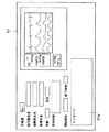
図7は、患者モニターシステム4の表示装置56の表示例である。領域56aは、測定した心電図、炭酸ガス分圧等の生体情報のトレンドをグラフ表示し、領域56bではそれらの数値のデジタル表示を行なう。領域56cでは、通信により手術システム3から得られた患者の気腹情報を表示し、腹腔圧設定値と測定した腹腔圧を確認することが出来る。領域56dは、メッセージ表示領域であり、図6に示した手術システム3の表示領域19fと同様の表示を行なう。「確認」表示を消滅させるためには、制御部50に設けてある図示しないスイッチを麻酔医が押すことによる。このスイッチ部分の構成は、表示装置56の表面にタッチセンサを設けた構成で、該当する部分を触れることで切り替えるという構成に変更しても実施可能である。確認のスイッチが押されると、麻酔医が確認したことを表す既読情報を、通信回路9を経由して、通信端末装置8ヘと発信する。
【0026】
図8は、医局7に配置される通信端末装置8の表示装置57の表示例である。本実施形態での表示項目は次の通りである。すなわち、執刀医の名前、麻酔医の名前、患者の名前、性別、及び年齢、現在行なわれている手術の術式、開始予定時刻、終了予定時刻である。これらの情報は予めデータべースに記録され、記憶装置61に格納されている。
【0027】
患者モニターシステム4から通信回路9を介して得た患者生体情報は、表示装置57の表示画面で、数値による表示とトレンドグラフによる表示とを選択することが出来る。また、手術システム3からの気腹情報も、文字情報として表示する。領域57aはメッセージ表示領域であり、患者生体情報が異常な値となった場合に、所要のメッセージを表示する。
【0028】
図9は、この領域57aに表示されるメッセージの一例である。図9の(A)は、患者モニターシステム4から通信により得た患者の生体情報が、例えば「患者の呼気炭酸ガス分圧が高くなっている」といった異常情報である場合の表示例を示す。この時点では、執刀医および麻酔医のいずれも何も行動を起こしていないため、「執刀医」および「麻酔医」のそれぞれ表示部に「未確認」と表示されている。
【0029】
上述のように、患者に異常が発生した場合には、手術システム3の表示装置19と患者モニターシステム4の表示装置56との両者に異常を知らせるのメッセージが表示される。したがって、執刀医および麻酔医が、この状況を把握した後、スイッチを押して確認行動をとると、これらの手術システム3と患者モニターシステムとは通信手段を介して、確認済みの情報を発信する。通信端末装置8は、この情報を取得すると、その領域57aの表示部に図9の(A)に示すように表示されている対応する「未確認」の表示を「確認済み」の表示(図示しない)に切り替える。また、執刀医あるいは麻酔医のいずれもが予め設定された待機時間(例えば1分間であり、必要に応じて変更可能である)にわたって確認行動をとらなかった場合は、通信端末装置8は、図9の(B)に示すようなメッセージ入力欄とこのメッセージの送信の問合せとを表示する。このような状態は麻酔医が不在か、あるいは執刀医が不慣れなために対応を判断できずにいると考えられるためである。これにより、医局にいる別の外科医、または麻酔医が、表示装置57の57のメッセージ入力欄に必要なメッセージを入力し、このメッセージを手術室に配置されている患者モニターシステム4、及び手術システム3の各表示装置56,19に表示させることが出来る。
【0030】
更に、医局側すなわち通信端末装置8のメッセージ入力欄に何も入力しない時間が一定時間(例えば5分以上)続いた場合には、制御部58は自動的に記憶装置61に記録されているデータベースの中から、この状況に該当する処置方法を選択し、手術システム及び患者モニターシステムの表示装置のメッセージ表示領域にその処置法を表示する。医局に誰も居ない状態と考えられるからである。一方、予め、医局の不在が分かっている場合には、設定によりこの待ち時間を省略させることが出来る。すなわち、執刀医あるいは麻酔医の確認が一定時間(例えば1分間)行われなかった場合には、直ちにデータベースの検索を行ない、対処方法を送信することも可能である。
【0031】
このような対処方法を受信した場合、患者モニターシステム4および手術システム3は、自動的に処置を行なうようにしてもよい。例えば、患者の呼気炭酸ガス分圧が高くなっている場合、本医療機器通信システムは、例えばシステムコントローラ22を通じて、患者モニターシステム4に接続されている人工呼吸器の換気頻度を高くし、あるいは、手術システム3に接続されている気腹装置14の作動を停止する等の処置を自動的に行わせても良い。
【0032】
更に、上述した情報交換の記録を通信端末装置8の記憶装置61に記録することが出来る。この記録は、手術後に自在に参照することが可能である。
【0033】
したがって、本実施形態の医療機器通信システムによれば、例え麻酔医が患者の生体情報の中から危険な状態を見逃した場合、あるいは執刀医が対応を判断できない場合でも、医局にいる医師からこの情報を直ちに外科医に知らせることができ、これにより、患者の危険を減少させることが出来る。また、異常時の適切な対処法を手術室の医師に提示することが出来るので、患者への危険を減少させることが出来ると共に、処置する際に、医師を補助して判断を導き出し易くすることができる。
【0034】
[第2実施形態]
図10から図12は、本発明の第2実施形態による医療機器通信システムを示す。
図10は本実施形態による医療機器通信システムの全体構成を概略的に示す。本実施形態の医療機器通信システムは、例えば病院内の第1,第2,第3手術室2,65,66である複数の手術室と、例えば医局7,67である複数の医局とを1つの通信回路9で接続している。各手術室2,65,66には、第1実施形態と同様な手術システム3および患者モニターシステム4が配置されており、更に、このような手術室(図示しない)を順次追加して接続することも可能である。
【0035】
医局7,67には、それぞれ第1実施形態と同様な通信端末装置8が配置されている。なお、これらの医局7,67は通常の病院内の医局に限るものではなく、医師あるいは看護婦が詰めることのできる場所であればどのような場所であってもよく、例えば大学病院の場合には、大学の研究室であってもよい。また、通信回路9で接続されるものであれば、同じ建物あるいは同じ病院内に限らず、離隔した建物あるいは異なる病院等に設置されていてもよい。更に、このような医局の数は図示のように2カ所に限られるものではなく、1カ所のみ、あるいは3ケ所以上に設けられていてもよい。
各手術室2,65,66,67内における各システムの動作は第1実施形態と同様であるためその説明を省略する。
【0036】
本実施形態の医療機器通信システムでは、一つの手術室で発生した患者生体情報の異常に対して、医局7から、対処方法を手術室内の患者モニターシステム4または手術システム3に指示し、この医局7で判断できないような場合には、専門医やベテランドクターのいるもう一つの医局67に対して、指示を仰ぐことが出来る。
【0037】
図12は、これら各医局6,67の通信端末装置8の表示例である。図12の(A)は、医局7の表示装置57の表示画面を示す。ここでは、例えば第1手術室2である手術室No.1のデータを拡大して表示している。医局7の医師が、手術室で発生した患者生体情報の異常に対して、問い合わせを行なう場合、領域57e内にある問い合わせ先入力欄57fに問い合わせ先を入力する。相手先医局が複数ある場合は、複数の医局を同時に選択できるようにしても良い。次に、メッセージ欄57gに必要に応じて文字を入力する。このメッセージ入力は音声によるデータ入力であっても良い。入力後、送信ボタン57hを押すことにより、指定した問い合わせ先に情報を送信する。
【0038】
図12の(B)は、このような問い合わせを受ける側すなわち問い合わせ先医局の通信端末装置8における表示画面71の表示例を示す。
医局7からの問い合わせ情報を受信すると、問い合わせ先医局の表示画面71は、図12の(B)に示すように表示される。すなわち、問い合わせ元が表示欄71bに表示され、医局7からのメッセージは、表示欄71cに表示される。また、その他の生体情報等のデータは、医局7で表示している内容と同じ内容が表示される。ここで、医局67のベテラン医師あるいは専門医は、この表示された生体情報等のデータを見てメッセージ欄71aに所要の指示内容を記入する。記入後、送信ボタン71dを押すことにより、指示内容は、医局7の表示装置57及び該当する手術室2の手術システム3の表示装置19のメッセージ領域19f(図5参照)に表示される。これにより、執刀医である術者は直ちに適切な指示を受けることが出来る。
【0039】
図11は、医局7の通信端末装置8の表示装置57の表示例を示す。各手術室2,65,66からの情報を画面上の領域57b,57c,57dにそれぞれ表示する。各領域57b,57c,57dの表示内容は、第1実施形態について説明した図8に示す表示画面の内容と同様である。また、各領域57b,57c,57dの表示は、使用者の選択により、一つの領域のみを拡大することが可能である。拡大した場合には、図8に示す表示画面と同様に表示される。
【0040】
本実施形態の医療機器通信システムによれば、複数の手術室2,65,66の状況を医局7で一括して管理することが出来る。また、複数の医局6,67および手術室2,65,66の間で情報交換ができるため、第1の医局が判断できないような状況でも、別の専門医やベテランドクターの意見や指示等を受けることが出来る。
【0041】
【発明の効果】
以上明らかなように、本発明の医療機器通信システムによると、手術システムと生体情報測定システムと医局用端末とをそれぞれの通信インターフェイスを介して通信手段に接続し、これらの間で情報通信を行うことにより、患者生体情報に異常が生じた場合に、外科医に、直ちに適切な判断を行なえるような情報提供を行なうことが出来る。
【図面の簡単な説明】
【図1】本発明の第1実施形態による医療機器通信システムの全体構成を示す説明図。
【図2】手術室に配置され、図1の医療機器通信システムを形成する内視鏡手術システムの概略図。
【図3】手術室に配置され、図1の医療機器通信システムを形成する患者モニターシステムの概略図。
【図4】医局に配置され、図1の医療機器通信システムを形成する通信端末装置の説明図。
【図5】図2に示す手術システムの表示画面の説明図。
【図6】図5の手術システムの表示画面に、生体情報の異常値を表示するときのの表示例の説明図。
【図7】患者モニターシステムの表示装置の表示例を示す説明図。
【図8】医局に配置される通信端末装置における表示装置の表示例を示す説明図。
【図9】図8の表示装置の一部領域に表示するメッセージの説明図。
【図10】第2実施形態による医療機器通信システムの全体構成を示す図1と同様な説明図。
【図11】図10の医療機器通信システムにおける通信端末装置の表示例を示す説明図。
【図12】問い合わせを受ける側の通信端末装置における表示画面に表示例を示す説明図。
【符号の説明】
1…医療機器通信システム、2…手術室、3…内視鏡手術システム、4…患者モニターシステム(生体情報測定システム)、5,6…通信コントローラ、7…医局、8…通信用端末装置(医局用端末)、9…通信回路(通信手段)。[0001]
BACKGROUND OF THE INVENTION
The present invention relates to a medical device communication system that provides patient biometric information measured during a surgical operation to a surgical system and a medical station terminal.
[0002]
[Prior art]
There is an endoscopic surgical system as one of surgical systems including a plurality of surgical devices and a system controller that collectively controls these surgical devices. A general endoscopic operation system includes an endoscope for performing observation, a camera head connected to the endoscope, a light source device that supplies illumination light to an observation site through the endoscope, and the camera. An endoscopic camera device that processes image signals captured by the head, a monitor that displays a subject image of an observation site processed by the endoscopic camera device, a pneumothorax device for expanding the abdominal cavity, and a procedure It is a surgical device for performing, and is composed of a plurality of medical devices such as a high-frequency ablation device for excising or coagulating a living tissue. These surgical devices are mainly operated and used by surgeons.
[0003]
On the other hand, in the operating room, there is a device called a patient monitor device, which is mainly monitored by an anesthesiologist. It is designed to centrally monitor the patient's biological information (hereinafter also referred to as vital signs), and is connected to an electrocardiograph, pulse oximeter, capnometer, etc. Vital signs such as medium oxygen saturation can be measured and displayed in a concentrated manner.
[0004]
There is also provided an in-hospital system in which a patient monitor in each operating room is connected to a CCU and a patient monitor installed in a hospital room by communication means, and monitoring and data recording are performed at a medical station or a nurse station.
[0005]
In Japanese Patent Application Laid-Open No. 7-303654, a means for displaying a function of a controlled device and a means for operating the controlled device in order to easily operate and control a plurality of surgical devices and improve operability as a system. A system control apparatus provided with the above is disclosed.
[0006]
Japanese Patent Laid-Open No. 11-318823 has means for inputting a signal from an external communication device, and display means for displaying on a display means as medical information based on the input signal, together with an endoscopic image. A medical device capable of displaying medical information from a place other than an operating room is disclosed. In addition, an anesthesia apparatus for measuring biological information of a patient is disclosed as an example of an external device, and a method of connecting a surgical apparatus and biological information of a patient by communication is disclosed.
[0007]
Furthermore, in Japanese Patent Application No. 11-176004, there is provided a medical system characterized by having a plurality of surgical systems and a communication means for connecting and transmitting data and transmitting / receiving data so that each system can possess shared data. Proposed.
[0008]
[Problems to be solved by the invention]
In the conventional medical device system described above, since the operation device and the patient monitor device are not linked, the communication means of the in-hospital system is required for each, and the device and the system become complicated and complicated. was there.
[0009]
In addition, when an anesthesiologist is absent during surgery, it takes time to find an anesthesiologist when the patient's subject information is abnormal and the surgeon cannot make an emergency response decision. There was a problem such as.
[0010]
The present invention has been made based on such circumstances, and a medical device communication system capable of providing information so that an appropriate judgment can be immediately made to a surgeon when abnormality occurs in patient biological information. The purpose is to provide.
[0011]
[Means for Solving the Problems]
The medical device communication system of the present invention has a system controller capable of collectively controlling a plurality of medical devices, and can communicate with at least one surgical system that can communicate with the outside via a communication interface and with the outside via the communication interface. And at least one biological information measurement system for measuring and monitoring patient biological information, a medical station terminal capable of communicating with the outside via a communication interface, the surgical system, the biological information measurement system, and the medical station terminal, And a communication means for performing information communication, and the system controller analyzes biological information measured by the biological information measuring system, and is used for the surgical system, the biological information measuring system, and the medical station. terminal and displays the analysis result on the information display means, the surgical system When at least one operator of the body information measurement system confirms the analysis result, the read information can be displayed on the information display means of the surgical system, the biological information measurement system, and the medical station terminal. When the read information is not input for a predetermined time from the display of the analysis result, information for dealing with the analysis result is transferred from the medical station terminal to at least one of the surgical system and the biological information measurement system. It becomes possible to provide .
[0012]
DETAILED DESCRIPTION OF THE INVENTION
[First Embodiment]
1 to 9 show a medical device communication system according to a first embodiment of the present invention.
As shown in FIG. 1, the medical
[0013]
FIG. 2 shows an
As shown in the figure, a
[0014]
Furthermore, a
[0015]
On the other hand, on the
[0016]
Therefore, the
[0017]
FIG. 3 shows a
The
[0018]
The
[0019]
Next, the configuration of the
The
[0020]
Next, the operation of the first embodiment configured as described above will be described.
The
[0021]
FIG. 5 illustrates an image displayed on the screen of the
[0022]
FIG. 6 shows an example of a message displayed in this
[0023]
FIG. 6A is a display example when an abnormal value is detected as a result of analyzing the biological information of the patient 48 by the
That is, the
[0024]
FIG. 6B is a display example when the surgeon confirms the abnormal state of the patient and presses a confirmation switch (not shown) provided in the
[0025]
FIG. 7 is a display example of the
[0026]
FIG. 8 is a display example of the
[0027]
The patient biometric information obtained from the
[0028]
FIG. 9 shows an example of a message displayed in this
[0029]
As described above, when an abnormality occurs in the patient, a message notifying the abnormality is displayed on both the
[0030]
Further, when a time during which nothing is input in the message input field of the medical station side, that is, the
[0031]
When such a countermeasure is received, the
[0032]
Further, the information exchange record described above can be recorded in the
[0033]
Therefore, according to the medical device communication system of the present embodiment, even if the anesthesiologist misses a dangerous state from the patient's biological information or the surgeon cannot determine the response, the doctor in the medical office Information can be immediately communicated to the surgeon, thereby reducing patient risk. In addition, since it is possible to present the appropriate countermeasures in the event of abnormalities to doctors in the operating room, it is possible to reduce the risk to the patient and to assist the doctors in deriving judgments during treatment. Can do.
[0034]
[Second Embodiment]
10 to 12 show a medical device communication system according to a second embodiment of the present invention.
FIG. 10 schematically shows the overall configuration of the medical device communication system according to the present embodiment. The medical device communication system according to the present embodiment includes, for example, a plurality of operating rooms that are first, second, and
[0035]
In the
Since the operation of each system in each
[0036]
In the medical device communication system according to the present embodiment, the
[0037]
FIG. 12 is a display example of the
[0038]
FIG. 12B shows a display example of the
When the inquiry information from the
[0039]
FIG. 11 shows a display example of the
[0040]
According to the medical device communication system of this embodiment, the
[0041]
【The invention's effect】
As is apparent from the above, according to the medical device communication system of the present invention, the surgical system, the biological information measurement system, and the medical station terminal are connected to the communication means via the respective communication interfaces, and information communication is performed therebetween. Thus, when an abnormality occurs in the patient biometric information, it is possible to provide the surgeon with information that can immediately make an appropriate determination.
[Brief description of the drawings]
FIG. 1 is an explanatory diagram showing an overall configuration of a medical device communication system according to a first embodiment of the present invention.
2 is a schematic view of an endoscopic surgical system that is disposed in an operating room and forms the medical device communication system of FIG.
3 is a schematic diagram of a patient monitoring system that is located in the operating room and forms the medical device communication system of FIG.
4 is an explanatory diagram of a communication terminal device that is arranged in a medical station and forms the medical device communication system of FIG. 1. FIG.
FIG. 5 is an explanatory diagram of a display screen of the surgical system shown in FIG.
6 is an explanatory diagram of a display example when an abnormal value of biological information is displayed on the display screen of the surgical system in FIG. 5. FIG.
FIG. 7 is an explanatory diagram showing a display example of the display device of the patient monitor system.
FIG. 8 is an explanatory diagram showing a display example of a display device in a communication terminal device arranged in a medical station.
FIG. 9 is an explanatory diagram of a message displayed in a partial area of the display device of FIG.
FIG. 10 is an explanatory view similar to FIG. 1, showing the overall configuration of the medical device communication system according to the second embodiment.
11 is an explanatory diagram showing a display example of a communication terminal device in the medical device communication system of FIG.
FIG. 12 is an explanatory diagram showing a display example on the display screen in the communication terminal device on the side of receiving an inquiry.
[Explanation of symbols]
DESCRIPTION OF
Claims (4)
通信インターフェイスを介して外部と通信可能で、患者生体情報を測定及び監視する少なくとも1つの生体情報測定システムと、
通信インターフェイスを介して外部と通信可能な医局用端末と、
前記手術システムと生体情報測定システムと医局用端末とに、それぞれの通信インターフェイスを介して接続し、情報通信を行う通信手段と、
を備え、
前記システムコントローラは、前記生体情報測定システムが測定した生体情報を解析し、前記手術システムと生体情報測定システムと医局用端末とは、この解析結果を情報表示手段に表示し、前記手術システムと生体情報測定システムとの少なくとも一方の操作者が、前記解析結果を確認したときに、前記手術システムと生体情報測定システムと医局用端末とのそれぞれの情報表示手段に既読情報を表示可能であり、前記既読情報が、解析結果の表示から所定時間入力されていないときに、前記医局用端末から前記手術システムと生体情報測定システムとの少なくとも一方へと前記解析結果に対処するための情報を提供することが可能となる医療機器通信システム。A system controller capable of collectively controlling a plurality of medical devices, and at least one surgical system capable of communicating with the outside via a communication interface;
At least one biological information measurement system capable of communicating with the outside via a communication interface and measuring and monitoring patient biological information;
A medical station terminal capable of communicating with the outside via a communication interface;
Communication means for connecting to the surgical system, the biological information measurement system, and the medical station terminal via respective communication interfaces, and performing information communication;
With
The system controller analyzes the biological information measured by the biological information measurement system, and the surgical system, the biological information measurement system, and the medical station terminal display the analysis result on an information display unit, and the surgical system and the biological information When at least one operator of the information measurement system confirms the analysis result, the read information can be displayed on each information display means of the surgical system, the biological information measurement system, and the medical station terminal, Providing information for dealing with the analysis result from the medical terminal to at least one of the surgical system and the biological information measurement system when the read information is not input for a predetermined time from the display of the analysis result Medical device communication system that can be used .
Priority Applications (1)
| Application Number | Priority Date | Filing Date | Title |
|---|---|---|---|
| JP2000261540A JP3877507B2 (en) | 2000-08-30 | 2000-08-30 | Medical device communication system |
Applications Claiming Priority (1)
| Application Number | Priority Date | Filing Date | Title |
|---|---|---|---|
| JP2000261540A JP3877507B2 (en) | 2000-08-30 | 2000-08-30 | Medical device communication system |
Publications (3)
| Publication Number | Publication Date |
|---|---|
| JP2002065618A JP2002065618A (en) | 2002-03-05 |
| JP2002065618A5 JP2002065618A5 (en) | 2004-09-09 |
| JP3877507B2 true JP3877507B2 (en) | 2007-02-07 |
Family
ID=18749367
Family Applications (1)
| Application Number | Title | Priority Date | Filing Date |
|---|---|---|---|
| JP2000261540A Expired - Fee Related JP3877507B2 (en) | 2000-08-30 | 2000-08-30 | Medical device communication system |
Country Status (1)
| Country | Link |
|---|---|
| JP (1) | JP3877507B2 (en) |
Cited By (1)
| Publication number | Priority date | Publication date | Assignee | Title |
|---|---|---|---|---|
| CN106175711A (en) * | 2016-07-14 | 2016-12-07 | 泰利美信(苏州)医疗科技有限公司 | Temperature patch and temperature acquisition system |
Families Citing this family (6)
| Publication number | Priority date | Publication date | Assignee | Title |
|---|---|---|---|---|
| WO2003094768A1 (en) * | 2002-05-07 | 2003-11-20 | Kyoto University | Medical cockpit system |
| US20040059205A1 (en) * | 2002-09-20 | 2004-03-25 | Sven-Erik Carlson | Configuration for monitoring the state of health of a person |
| US7978208B2 (en) * | 2007-04-16 | 2011-07-12 | General Electric Company | Systems and methods for multi-source video distribution and composite display |
| US20110301426A1 (en) * | 2010-06-04 | 2011-12-08 | Yongji Fu | Method and device for conditioning display of physiological parameter estimates on conformance with expectations |
| JP2012061230A (en) * | 2010-09-17 | 2012-03-29 | Nec Software Kyushu Ltd | Abnormality notification apparatus, method and program |
| JP6359264B2 (en) * | 2013-11-15 | 2018-07-18 | キヤノンメディカルシステムズ株式会社 | Surgery information management device |
-
2000
- 2000-08-30 JP JP2000261540A patent/JP3877507B2/en not_active Expired - Fee Related
Cited By (1)
| Publication number | Priority date | Publication date | Assignee | Title |
|---|---|---|---|---|
| CN106175711A (en) * | 2016-07-14 | 2016-12-07 | 泰利美信(苏州)医疗科技有限公司 | Temperature patch and temperature acquisition system |
Also Published As
| Publication number | Publication date |
|---|---|
| JP2002065618A (en) | 2002-03-05 |
Similar Documents
| Publication | Publication Date | Title |
|---|---|---|
| JP4869951B2 (en) | Medical device data analyzer | |
| US7413541B2 (en) | Surgery support system for endoscopic surgery | |
| EP1839568B1 (en) | Operation data management device, operation control device, and operation data processing method | |
| JP2006223375A (en) | Surgery data recorder, surgery data display device and surgery data recording and displaying method | |
| JP2007330347A (en) | Surgical operation system and its system operation information notifying method | |
| US8154589B2 (en) | Medical operation system for verifying and analyzing a medical operation | |
| JP3877507B2 (en) | Medical device communication system | |
| WO2005084525A1 (en) | Image processing device | |
| JP2006061702A (en) | Surgical system | |
| JP5010778B2 (en) | Endoscopic surgery system | |
| JP3794901B2 (en) | Surgery system | |
| JPH07303654A (en) | System control device | |
| US20170231478A1 (en) | Medical system | |
| JP2007082630A (en) | Integrated operation room control system | |
| JP2004165728A (en) | Control system | |
| JP3866990B2 (en) | Control system | |
| JP2004121613A (en) | Medical controlling device | |
| JP2007075520A (en) | Surgery analyzer | |
| JP4217295B2 (en) | Medical equipment | |
| JP2002065574A (en) | Operation system | |
| JP2006218236A (en) | Surgery control system | |
| JP2000126202A (en) | Surgery integrating device | |
| US20200090807A1 (en) | Wireless head mounted telemetry display and communication system | |
| JP2002233536A (en) | Endoscopic operation system | |
| JPH0654811A (en) | Patient monitoring device |
Legal Events
| Date | Code | Title | Description |
|---|---|---|---|
| A131 | Notification of reasons for refusal |
Free format text: JAPANESE INTERMEDIATE CODE: A131 Effective date: 20060509 |
|
| A521 | Request for written amendment filed |
Free format text: JAPANESE INTERMEDIATE CODE: A523 Effective date: 20060626 |
|
| A131 | Notification of reasons for refusal |
Free format text: JAPANESE INTERMEDIATE CODE: A131 Effective date: 20060808 |
|
| A521 | Request for written amendment filed |
Free format text: JAPANESE INTERMEDIATE CODE: A523 Effective date: 20060927 |
|
| TRDD | Decision of grant or rejection written | ||
| A01 | Written decision to grant a patent or to grant a registration (utility model) |
Free format text: JAPANESE INTERMEDIATE CODE: A01 Effective date: 20061024 |
|
| A61 | First payment of annual fees (during grant procedure) |
Free format text: JAPANESE INTERMEDIATE CODE: A61 Effective date: 20061031 |
|
| FPAY | Renewal fee payment (event date is renewal date of database) |
Free format text: PAYMENT UNTIL: 20101110 Year of fee payment: 4 |
|
| FPAY | Renewal fee payment (event date is renewal date of database) |
Free format text: PAYMENT UNTIL: 20101110 Year of fee payment: 4 |
|
| FPAY | Renewal fee payment (event date is renewal date of database) |
Free format text: PAYMENT UNTIL: 20111110 Year of fee payment: 5 |
|
| FPAY | Renewal fee payment (event date is renewal date of database) |
Free format text: PAYMENT UNTIL: 20111110 Year of fee payment: 5 |
|
| FPAY | Renewal fee payment (event date is renewal date of database) |
Free format text: PAYMENT UNTIL: 20121110 Year of fee payment: 6 |
|
| FPAY | Renewal fee payment (event date is renewal date of database) |
Free format text: PAYMENT UNTIL: 20131110 Year of fee payment: 7 |
|
| LAPS | Cancellation because of no payment of annual fees |