JP3577028B2 - Robot cooperative control system - Google Patents
Robot cooperative control system Download PDFInfo
- Publication number
- JP3577028B2 JP3577028B2 JP2001341905A JP2001341905A JP3577028B2 JP 3577028 B2 JP3577028 B2 JP 3577028B2 JP 2001341905 A JP2001341905 A JP 2001341905A JP 2001341905 A JP2001341905 A JP 2001341905A JP 3577028 B2 JP3577028 B2 JP 3577028B2
- Authority
- JP
- Japan
- Prior art keywords
- robot
- control device
- execution mode
- function execution
- slave
- Prior art date
- Legal status (The legal status is an assumption and is not a legal conclusion. Google has not performed a legal analysis and makes no representation as to the accuracy of the status listed.)
- Expired - Lifetime
Links
Images


Classifications
-
- B—PERFORMING OPERATIONS; TRANSPORTING
- B25—HAND TOOLS; PORTABLE POWER-DRIVEN TOOLS; MANIPULATORS
- B25J—MANIPULATORS; CHAMBERS PROVIDED WITH MANIPULATION DEVICES
- B25J9/00—Programme-controlled manipulators
- B25J9/16—Programme controls
- B25J9/1679—Programme controls characterised by the tasks executed
- B25J9/1682—Dual arm manipulator; Coordination of several manipulators
-
- G—PHYSICS
- G05—CONTROLLING; REGULATING
- G05B—CONTROL OR REGULATING SYSTEMS IN GENERAL; FUNCTIONAL ELEMENTS OF SUCH SYSTEMS; MONITORING OR TESTING ARRANGEMENTS FOR SUCH SYSTEMS OR ELEMENTS
- G05B2219/00—Program-control systems
- G05B2219/30—Nc systems
- G05B2219/33—Director till display
- G05B2219/33097—Variable ticks, align clocks, to synchronise cycles with other machine, robot
-
- G—PHYSICS
- G05—CONTROLLING; REGULATING
- G05B—CONTROL OR REGULATING SYSTEMS IN GENERAL; FUNCTIONAL ELEMENTS OF SUCH SYSTEMS; MONITORING OR TESTING ARRANGEMENTS FOR SUCH SYSTEMS OR ELEMENTS
- G05B2219/00—Program-control systems
- G05B2219/30—Nc systems
- G05B2219/39—Robotics, robotics to robotics hand
- G05B2219/39051—Calibration cooperating manipulators, closed kinematic chain by alignment
-
- G—PHYSICS
- G05—CONTROLLING; REGULATING
- G05B—CONTROL OR REGULATING SYSTEMS IN GENERAL; FUNCTIONAL ELEMENTS OF SUCH SYSTEMS; MONITORING OR TESTING ARRANGEMENTS FOR SUCH SYSTEMS OR ELEMENTS
- G05B2219/00—Program-control systems
- G05B2219/30—Nc systems
- G05B2219/39—Robotics, robotics to robotics hand
- G05B2219/39124—Grasp common rigid object, no movement end effectors relative to object
-
- G—PHYSICS
- G05—CONTROLLING; REGULATING
- G05B—CONTROL OR REGULATING SYSTEMS IN GENERAL; FUNCTIONAL ELEMENTS OF SUCH SYSTEMS; MONITORING OR TESTING ARRANGEMENTS FOR SUCH SYSTEMS OR ELEMENTS
- G05B2219/00—Program-control systems
- G05B2219/30—Nc systems
- G05B2219/39—Robotics, robotics to robotics hand
- G05B2219/39141—Slave program has no taught positions, receives position from master, convert from master
Landscapes
- Engineering & Computer Science (AREA)
- Robotics (AREA)
- Mechanical Engineering (AREA)
- Manipulator (AREA)
- Numerical Control (AREA)
Description
【0001】
【発明の属する技術分野】
本発明は、複数のロボット毎に設けられるロボットコントローラとも呼ばれる制御装置を、通信ネットワークによって接続し、各ロボットを協調動作させるロボットの協調制御システムに関する。
【0002】
【従来の技術】
従来から、ワークが重量物または大型物である場合、複数台のロボットによって、前記ワークを確実に把持した状態を維持しながら、予め設定された出発点から到達点にわたる複数の教示点および各教示点間の補間点を経て、正確にかつ安定して搬送する協調動作を実現するために、各ロボットを協調制御する協調制御システムが採用されている。
【0003】
このような複数台のロボットを用いる協調制御システムにおいては、作業空間内におけるロボットの配置位置に応じた複数箇所で前記ワークを把持することができるため、前記ワークが大型物であっても、安定した搬送が可能である。また、前記ワークが重量物であっても、複数のロボットにワークの重量が分散されるので、各ロボットの重量負荷および慣性負荷が少なく、搬送速度を大きくして搬送時間を短縮することができる。
【0004】
前記協調制御システムには、複数のロボットを1台の制御装置によって統括的に制御する「多:1」のシステムと、各ロボット毎に対応する制御装置が個別に設けられる「1:1」のシステムとがある。複数のロボットを1台の制御装置で統括的に制御する「多:1」のシステムでは、1台の制御装置によって複数台のロボットを制御しなければならないために、制御装置が特殊な構成となる。
【0005】
これに対して、複数のロボット毎に制御装置を設けて各ロボットを個別に制御する「1:1」のシステムでは、1台のロボットを1台の制御装置によって制御するため、上記「多:1」のシステムのように特殊な構成を有する制御装置を用いる必要がなく、汎用の制御装置を用いることができる。したがって「多:1」のシステムに比べて、協調制御用プログラムを導入して、容易に協調制御システムを実現することができ、実現容易性の点で優れている。
【0006】
しかも、前記汎用の制御装置は、協調制御システムを構築せずに、単独で他の用途に用いることが可能であり、制御装置の購入コストを節約することができ、経済的であるという利点を有している。さらにまた、ロボット台数を自在に変更することができるため、システムの設計に際して自在に対応することができ、システム設計に対する自由度が高いという利点を有している。
【0007】
さらに他の従来の技術では、上記の複数のロボットに対して個別に制御装置を設ける「1:1」の個別協調制御システムにおいて、各ロボットについてプログラムを作成し、インタロックを用いて搬送動作を制御する個別制御システムと、複数のロボットのうちの1台をマスタロボットに設定し、マスタロボットを除く他のロボットは、前記マスタロボットに同期して追従するスレーブロボットに設定し、マスタロボットに対して実装されるソフトウェアプログラムによって、マスタロボットおよびスレーブロボットを協調制御して、ワークを搬送するマスタ/スレーブ協調制御システムとが周知である。
【0008】
上記のマスタ/スレーブ協調制御システムでは、ワークの変更および搬送条件の変更などによってロボットの動作を変更する必要が生じた場合、前記マスタロボットに実装されるプログラムだけを変更すればよいので、プログラムの変更、作成および管理が容易であるという利点を有している。そのため、汎用ロボットコントローラによって実現される複数の制御装置のうちから1台のマスタ制御装置を選択して、残余の1または複数のスレーブ制御装置を協調動作させている。
【0009】
このようなマスタ・スレーブ間で協調制御を行うシステムにおいては、バス結合または通信回線によって接続された各制御装置間でデータの送受信を行う場合、個々に独立して各ロボット毎に制御系を構成する各制御装置は、相互に同期させる必要がある。この同期をとるための手法としては、各制御装置間がバス結合され、かつ共有メモリ方式によって各制御装置間でデータの送受信を行う場合、共有メモリ上にフラグを設ける手法と、割込みを利用し、割り込み処理内でイベントを発生させる手法とがある。
【0010】
図11は、従来の技術のマスタ/スレーブ協調制御システムにおけるマスタロボットおよびスレーブロボットの各制御装置A,Bを同期させるためのソフトウェアプログラム上の構成の一部を示すブロック図である。この従来の技術は、共有メモリ方式によって各制御装置A,B間を同期させるために、マスタロボットを制御するマスタ側制御装置Aと、スレーブロボットを制御するスレーブ側制御装置Bとについて見ると、マスタ側制御装置Aの演算処理装置2は、スレーブ側制御装置Bの共有メモリ3のフラグ4に指令値を書き込み、スレーブ側制御装置Bの演算処理装置5は、共有メモリ3上のフラグ4に前記指令値が書き込まれるまで待機し、スレーブ側制御装置Bの演算処理装置5の演算処理動作が終了した後、フラグ4を監視するために、ポーリング動作に入り、非同期時に発生するイベントを処理することができるように構成されている。
【0011】
図12は、他の従来の技術のマスタ/スレーブ協調制御システムに用いられる割込み方式によって各制御装置A,Bを同期させる手法を説明するためのブロック図である。各制御装置A,B間において、一方の制御装置Aの演算処理装置11からの割込み指令を、通信回線10を介して他方の制御装置Bが入力すると、他方の制御装置Bは、割込み処理手段12が起動し、この割込み処理手段12内でイベントを発生させて、演算処理手段13を起動させる。この他方の制御装置Bの演算処理手段13は、前記イベント処理を終了すると、再びイベント待ち状態になる。
【0012】
さらに他の従来の技術は、特開平7−20915号公報に示されている。この従来の技術では、協調動作の制御対象とされるアームを有する2台のロボットと、各ロボットを個別に制御する制御装置とを備え、各ロボットのうちで一方のロボットをマスタロボットとし、他方のロボットをスレーブロボットとして、協調制御するロボットの協調制御システムが開示されている。
【0013】
各制御装置は、教示点データに基づいて補間計算を行い、マスタロボットのアームの移動すべき通過点を決定し、スレーブロボットのアームの次通過点は、前記マスタロボットのアームが次に移動すべき点と、運搬中のワークの状態などに対応する両アームの相対的な位置および姿勢関係とに基づいて、各制御装置のうちのいずれか一方の制御装置内で決定される。マスタ側制御装置は、与えられた教示内容に応じてアームの次通過点を決定し、そのデータをスレーブ側制御装置に送信し、スレーブロボットのアームの次通過点が決定される。これらの制御装置は、上記のように相互のデータを送受信するために通信回線によって接続される。また各制御装置は同期をとるために、各制御装置のCPU(中央演算処理装置)が内蔵しているクロック発振回路からのクロック信号を用い、協調動作するために必要なデータおよびプログラムは、すべてのマスタロボットおよびスレーブロボットに共通の制御装置のメモリに格納されている。
【0014】
【発明が解決しようとする課題】
上記の図11および図12に示される各従来の技術では、他方の制御装置Bにとっては、フラグに対するポーリングおよびイベント待ちなどの無駄な待ち時間が発生してしまうという問題を有する。また上記の特開平7−20915号公報に示される従来の技術では、マスタアームとスレーブアームとを協調動作させるために、各制御装置を同期させるにあたって、各制御装置の同期信号間の微小な差、送信周期と受信周期との微小な差の蓄積による制御周期のずれ、および通信回線による不可避的な通信遅れなどを解消する具体的対策が採られていないため、複数の制御装置を常に同期させた状態に維持することができないという問題がある。さらに、ロボット毎に設けられる各制御手段にそれぞれ備えられる入力手段から動作指令を入力する手法、ロボット毎の入出力手段間の信号の送受信処理の手法、および各ロボットの相対位置の設定に誤差が生じたときの対処の仕方については、何ら考慮されていないため、実際上、協調制御システムを構築することは不可能である。
【0015】
本発明の目的は、複数の制御装置間の同期ずれを解消し、各ロボットの協調動作のずれを防止することができるようにしたロボットの協調制御システムを提供することである。
【0016】
【課題を解決するための手段】
請求項1記載の本発明は、複数のロボット毎に、各ロボットの動作を、予め定める最小割込み周期で発生されるタイミング信号に同期して、個別に制御する複数の制御装置と、
各制御装置を、相互に通信可能に接続してネットワークを構成する通信接続手段と、
各制御装置毎に設けられ、各ロボットの動作指令を入力する入力手段と、
各制御装置に設けられ、各ロボットの動作指令に応答して各ロボットを動作させるプログラムが記憶される記憶手段と、
各制御装置毎に設けられ、前記最小割込み周期でタイミング信号を発生するタイミング信号発生手段と含み、
各制御装置は、単独機能実行モード、マスタ機能実行モードおよびスレーブ機能実行モードのうちの少なくとも1つを、前記記憶手段に格納されたプログラムによって選択的に実行可能とされ、
各制御装置のうちの1つが前記プログラムの実行によってマスタ機能実行モードに設定されたとき、各制御装置のうちの前記マスタ機能実行モードに設定された制御装置を除く残余の制御装置のうち少なくとも1つが前記プログラムの実行によってスレーブ動作を実行するスレーブ機能実行モードに設定され、
前記スレーブ機能実行モードに設定された制御装置は、マスタ機能実行モードの制御装置が動作指令を送信した時刻taからスレーブ機能実行モードの制御装置が前記動作指令を受信して自己のロボットの制御を開始する時刻tbまでの通信遅れ時間(tb−ta)が、予め定める時間Tになるように、前記スレーブ機能実行モードに設定された制御装置の最小割込み周期Ts(b)を変化させ、
マスタ機能実行モードに設定された制御装置によって制御されるマスタロボットと、スレーブ機能実行モードに設定された制御装置によって制御されるスレーブロボットとは、協調動作することを特徴とするロボットの協調制御システムである。
【0017】
本発明に従えば、複数のロボット毎に制御装置が設けられ、各制御装置は、各ロボットの動作を、タイミング信号発生手段から予め定める最小割込み周期で発生されるタイミング信号に同期して、個別に制御する。各制御装置は、通信接続手段によって相互に通信可能に接続され、各制御装置間に通信ネットワークが構築される。各制御装置は、入力手段をそれぞれ備え、各ロボットの単独動作および協調動作を行う際に必要な教示データなどを入力することができる。また記憶手段には、各ロボット毎に予め定める動作指令に応答して各ロボットを動作させるプログラムが格納され、このプログラムの実行によって、各制御装置は、単独機能実行モード、マスタ機能実行モードおよびスレーブ機能実行モードのいずれかに選択的に設定され、1つの制御装置がマスタ機能実行モードに設定されると、残余の制御装置の全部または一部がスレーブ機能実行モードに設定される。
【0018】
このように各制御装置は、プログラムによって単独機能実行モード、マスタ機能実行モードおよびスレーブ機能実行モードのいずれか1つを選択的に設定可能とされるので、各制御装置のうちでマスタ動作させるべきロボットの制御装置、スレーブ動作させるべきロボットの制御装置、および単独動作させるべきロボットの制御装置をプログラム上に命令として記載しておくことによって、その選択された制御装置は、マスタ動作を実行するマスタ実行モードに設定される。また残余の制御装置のうちでスレーブ動作させるべき制御装置の一部または全部を選択、具体的にはプログラム上の命令として設定しておくことによって、その選択された制御装置は、スレーブ動作を実行するスレーブ実行モードに設定される。
【0019】
このようにして各ロボットが実行する一連の作業のうちで、協調動作する行程については、各ロボットをマスタロボットとスレーブロボットとに設定して、前記通信接続手段を介して相互に通信し、高精度で同期させて協調動作させることができる。
【0021】
また、スレーブ機能実行モードの制御装置は、マスタ機能実行モードの制御装置が動作指令を送信した時刻taから、スレーブ機能実行モードの制御装置が前記動作指令を受信して自己のロボットの制御を開始する時刻tbまでの通信遅れ時間(tb−ta)が予め定める時間Tとなるように、最小割込み周期を変化させるので、スレーブ側制御装置が自己のロボットに対する制御を開始する時刻tbが、前記マスタ側制御装置がマスタ側制御装置に対して動作指令を送信した時刻taに対して、前記予め定める時間Tよりも長くなる方向および予め定める時間Tよりも短くなる方向に大きくずれることが防がれる。これによってスレーブロボットのマスタロボットに対する動作上の時間的ずれを制限して、各ロボットを正確に協調動作させることが可能となる。
【0022】
請求項2記載の本発明は、請求項1記載のロボットの協調制御システムにおいて、前記予め定める時間Tは、各制御装置の制御周期W以下に選ばれることを特徴とする。
【0023】
本発明に従えば、前記予め定める時間Tが各制御装置の制御周期W以下に選ばれるので、マスタ側制御装置から動作指令が送信される時刻taから、スレーブ側制御装置によって受信されて、このスレーブ側制御装置が自己のロボットの制御を開始する時刻tbまでの時間(tb−ta)が、制御周期Wを超えてしまうことが防がれる。これによってスレーブ側制御装置は、スレーブ側制御装置の1制御周期Wの時間内に、マスタ側制御装置から複数の動作指令を受信してしまうという不具合が発生を確実に防止し、マスタロボットとスレーブロボットとを高精度で協調動作させることが可能となる。
【0024】
請求項3記載の本発明は、請求項2記載のロボットの協調制御システムにおいて、前記マスタ機能実行モードに設定された制御装置は、自己の対象とするロボットへの指令を、スレ−ブ機能実行モードの制御装置に対する前記通信遅れ時間(tb−ta)だけ遅延させて送信することを特徴とする。
【0025】
本発明に従えば、マスタ機能実行モードの制御装置が指令を送信して、これをスレーブ機能実行モードの制御装置が受信するまでには、通信による遅れ時間(tb−ta)が存在し、マスタロボットとスレーブロボットとの間には動作上のずれが発生する。これを防止するために、マスタ機能実行モードの制御装置が制御するロボットに対する指令を、スレ−ブ機能実行モ−ドの制御装置の通信遅れ時間(tb−ta)だけ遅延させて送信することによって、システム全体の設定を変更せずにマスタロボットに対するスレーブロボットの動作の遅れを防止し、各ロボットを高精度で同期させて、協調動作させることができる。
【0026】
請求項4記載の本発明は、請求項1〜3のいずれか1つに記載の協調制御システムにおいて、前記協調動作は、スレーブ機能実行モードに設定された制御装置が入力手段から動作指令を入力したとき、その動作指令は、前記通信接続手段を介してマスタ機能実行モードに設定された制御装置に入力され、このマスタ機能実行モードに設定された制御装置は、前記入力した動作指令に応答して制御動作を実行することを特徴とする。
【0027】
本発明に従えば、スレーブ機能実行モードの制御装置は、入力手段から動作指令を入力すると、この動作指令は、通信接続手段を介してマスタ機能実行モードの制御装置に入力される。このマスタ機能実行モードの制御装置は、入力した動作指令に応答して制御動作を実行し、こうしてスレーブ側制御装置からの動作指令の入力によって、マスタロボットを制御することができる。したがってオペレータは、マスタ側制御装置からだけではなく、スレーブ側制御装置側からも動作指令を入力して、場所的にスレーブロボットから離れた位置に設置されているマスタロボットの動作を設定することができ、したがって協調制御システム全体を操作者の希望する場所から操作することが可能となり、操作上の利便性が向上される。
【0028】
請求項5記載の本発明は、請求項1〜4のいずれか1つに記載のロボットの協調制御システムにおいて、協調動作中は各制御装置毎に入出力装置が設けられ、各制御装置のうちでマスタ機能実行モードに設定された制御装置と、スレーブ機能実行モードに設定された制御装置とは、前記通信接続手段を介して、マスタ機能実行モードに設定された制御装置が、スレーブ機能実行モードに設定された制御装置の入出力装置を使用して信号を入出力することを特徴とする。
【0029】
本発明に従えば、スレーブ機能実行モードの制御装置によって制御されるロボットに接続されたエンドエフェクタなどの外部機器は、スレーブ機能実行モードに設定された制御手段の入出力装置(略称IO)を用いて行なわれる。協調動作においては、マスタロボット側の記憶手段に記憶されたプログラムの動作命令にしたがって動作するため、スレーブロボットに接続された外部機器の制御は、マスタロボットの制御装置に設けられる入出力装置を用いて行なわれ、そのために信号の配線が煩雑になり、スレーブロボットを単独で使用しようとした場合に、マスタロボットの信号の影響を受けてしまう。このような不具合は、上記のようにマスタロボットがスレーブ側制御装置の入出力装置を用いることによって、回避することができる。
【0030】
請求項6記載の本発明は、請求項1〜5のいずれか1つに記載のロボットの協調制御システムにおいて、各制御装置は、協調動作中に各制御装置の協調動作を停止するための緊急停止手段をそれぞれ有し、各緊急停止手段のうちのいずれか1つから発生した緊急停止信号は、この緊急停止信号を発生した緊急停止手段が設けられる制御手段に入力されるとともに、残余の制御手段に前記通信接続手段を介して入力され、全てのロボットの動作を停止させることを特徴とする。
【0031】
本発明に従えば、各制御装置には緊急停止手段が備えられるので、どの位置のロボットからでも、異常が発生したときに、前記緊急停止手段を用いて各ロボットの一部または全体を緊急停止させることができ、これによって安全性が向上される。
【0032】
請求項7記載の本発明は、請求項1〜6のいずれか1つに記載のロボットの協調制御システムにおいて、各制御装置には、各ロボット毎に座標系が設定され、各ロボットのアームの先端部に寸法が既知である位置決め用ツールを着脱可能に設け、相互に隣接する各ロボットの位置決め用ツールの先端部を、少なくとも3点で突き合わせて同一位置に配置することによって、各ロボット用の座標変換行列を求め、この座標変換行列を用いて前記協調動作を実行することを特徴とする。
【0033】
本発明に従えば、マスタ座標系に設定された共通な3点を結ぶ仮想フレームを基準にして協調動作するので、各制御装置は、各ロボットの位置および姿勢、さらには位置および姿勢のずれを、常に共通な座標系上で各ロボットが相対的位置を正確に認識可能とし、各ロボットのうちで、いずれのロボットをマスタとして設定しかつスレーブとして設定しても、1つの座標系内で協調動作を高精度で制御することができる。
【0034】
請求項8記載の本発明は、請求項7記載のロボットの協調制御システムにおいて、前記協調動作において、スレーブ機能実行モードに設定されているロボットの前記マスタ機能実行モードに設定されているロボットに対する相対位置は、教示された動作開始点での相対位置関係と、教示された動作終了点での相対位置関係と満たすように補間することを特徴とする。
【0035】
本発明に従えば、マスタおよびスレーブの各ロボット間の相対位置関係において、マスタロボットとスレーブロボットとが実際の相対位置関係と設定された相対位置変換行列との間にずれがある場合、ツールの寸法に誤差がある場合、ロボットリンク長のばらつきがある場合、ゼロイング精度とも呼ばれるロボットの基準位置への設置精度自体にばらつきがある場合、ならびに負荷によるロボットアームのたわみの影響によって、相対的な位置および姿勢関係を一定に保つように制御しても、実際の位置および姿勢関係が一定に保たれない場合などの相対位置がずれる原因が存在しても、上記のようにマスタ機能実行モードに設定されたロボットの教示位置の他に、スレーブ機能実行モードに設定されるロボットの位置をも教示することによって、相対位置および姿勢を変更しながらスレーブロボットをマスタロボットに追従させて協調動作させることが可能となる。これによってマスタおよびスレーブの各ロボットの相対位置および姿勢のずれが時間経過とともに拡大することが防がれ、相対位置および姿勢関係を高精度に維持しながら、所定の動作を継続的に実行することができる。
【0036】
【発明の実施の形態】
図1は、本発明の実施の一形態のロボットの協調制御システム20の全体の構成を示す系統図である。本実施の形態のロボットの協調制御システム(以下、単に協調制御システムと略記する場合がある)20は、複数(本実施の形態では2)のロボットRa,Rbと、各ロボットRa,Rbを相互に個別に独立して制御する2台の制御装置Ca,Cbと、各制御装置Ca,Cbを相互に通信可能に接続する通信接続手段21とを含む。
【0037】
各ロボットRa,Rbは、一例として述べると、工場内の所定の作業ステージの略水平な床22上に相互に間隔をあけて設置される基台23上に、旋回体24が設けられ、旋回体24には複数のアーム25,26,27が各軸まわりに角変位可能に設けられ、最も遊端側のアームの先端部には手首28が設けられ、この手首28にはワーク29を着脱可能に把持するハンド30が設けられる6軸の多関節ロボットによってそれぞれ実現される。
【0038】
各制御装置Ca,Cbは、ロボットコントローラとも呼ばれ、相互に前記通信接続手段21によって接続されて、通信ネットワークを構成する。これらの制御装置Ca,Cbは、各ロボットRa,Rbにライン31a,31bによってそれぞれ接続される制御装置本体33a,33bと、ティーチペンダントとも呼ばれ、各制御装置本体33a,33bにライン35a,35bによって接続される教示入力手段37a,37bと有する。
【0039】
前記通信接続手段21は、イーサネット(Ethernet)によって実現される。本実施の形態において「イーサネット」とは、米国電気電子学会(略称IEEE;Institute of Electrical and Electronic Engineers)および国際標準化機構(略称IOS;International Organization For Standardization)によって、IEEE802.3およびISO8802−3として標準化されたLAN(Local Area Network)をいう。
【0040】
図2は、各制御装置Ca,Cbの構成を示すブロック図である。上記の各制御装置Ca,Cbには、各ロボットRa,Rbにそれぞれ備えられる図示しないサーボモータを駆動するためのサーボ駆動手段41a,41b、パワーシーケンス回路42a,42b、各ロボットRa,Rbに動作指令を入力するための操作パネル43a,43b、中央演算処理装置(略称CPU)によって実現される制御手段44a,44b、メモリ45a,45b、前記教示入力手段37a,37b、教示入力手段用インターフェイス回路46a,46b、パーソナルコンピュータ用インターフェイス回路(以下、PC用インターフェイス回路と略記する)47a,47b、信号入出力回路48a,48b、および通信制御手段49a,49bを含む。前記遠隔制御装置用インターフェイス回路47a,47bには、パーソナルコンピュータ(以下、PCと略記する場合がある)53a,53bが接続される。
【0041】
前記パワーシーケンス回路42a,42b、メモリ45a,45b、教示入力手段用インターフェイス回路46a,46b、PC用インターフェイス回路47a,47b、信号入出力回路48a,48b、および通信制御手段49a,49bは、バスライン50a,50bによって相互に接続される。各操作パネル43a,43bには、各ロボットRa,Rbの動作を停止するための停止指令を入力するための停止スイッチSW1,SW2と、緊急停止スイッチSW5,SW6とが設けられる。また、信号入出力回路48a,48bには、ハンド開閉検出スイッチSW3,SW4が接続される。
【0042】
前記通信接続手段21は、ハブ(HUB)51、各制御装置Ca,Cbに設けられる通信制御手段49a,49b、および通信ケーブル52a,52bを含む。各通信ケーブル52a,52bは、各通信制御手段49a,49bとハブ51とをそれぞれ接続し、通信ネットワークを構成する。
【0043】
図3は、各制御装置Ca,Cbのソフトウェア上の構成を示すブロック図である。各制御装置Ca,Cbは、各メモリ45a,45bにそれぞれ格納されるプログラムを実行するために、プログラム格納部61a,61b、プログラム実行解釈部62a,62b、スレーブ指令値生成部63a,63b、動作指令値生成部64a,64b、指令値送信部65a,65b、指令値遅延部66a,66b,指令値受信部67a,67b、割込み処理部68a,68b、クロック発生部69a,69b、および信号経路切換え部71a,71bを含む。
【0044】
各制御装置Ca,Cbは、前記メモリ45a,45bに格納されるプログラムによって、単独機能実行モード、マスタ機能実行モード、およびスレーブ機能実行モードのいずれかにそれぞれ設定され、各制御装置Ca,Cbのいずれか一方がマスタ機能実行モードに設定されると、各制御装置Ca,Cbのいずれか他方はスレーブ機能実行モードに設定され、各制御装置Ca,Cbによって制御される各ロボットRa,Rbを協調動作させることができるように構成される。
【0045】
図4は、各制御装置Ca,Cbの同期処理機能を説明するための図である。各制御装置Ca,Cbは、同様な同期処理機能を有し、便宜上、マスタ機能実行モードに設定された一方の制御装置Caを送信側とし、スレ−ブ機能実行モードに設定された他方の制御装置Cbを受信側として説明する。一方の制御装置Caから所定の制御周期Wで時刻ta1,ta2,ta3,…毎に送信された指令信号は、通信接続手段21を介して他方の制御装置Cbに前回のスレーブロボットRbへの制御時刻tb0,tb1,tb2…から所定時間Δt1,Δt2,Δt3,…経過後の各時刻(tb0+Δt1),(tb1+Δt2),(tb2+Δt3),…において時系列的に受信される。
【0046】
このようなマスタ側制御装置Caからスレーブ側制御装置Cbへの動作指令の通信接続手段21を介する送信では、各制御装置Ca,Cbの制御手段44a,44b(略称CPU)に内臓される水晶発振器の個体差による発振周波数の微小な誤差に起因する受信時刻(tb0+Δt1),(tb1+Δt2),(tb2+Δt3),…の送信時刻ta1,ta2,ta3…に対する第1の通信遅れ時間、および前記通信接続手段21を介することによる通信遅れ時間とスレーブ側制御装置Cbがマスタ側制御装置Caからの動作指令1,2,3,…を受信時刻(tb0+Δt1),(tb1+Δt2),(tb2+Δt3),…で受信してからスレーブロボットRbの制御を開始する制御時刻tb1,tb2,tb3,…までのタイムラグによる第2の通信遅れ時間が存在するため、前記一方の制御装置Caによって制御されるマスタロボットRaの動作に対して、他方の制御装置Cbによって制御されるスレ−ブロボットRbの動作のずれが発生し、同一時刻における各ロボットRa,Rb間の相対位置のずれは、作業精度上、無視できなくなってしまう。
【0047】
上記第1の通信遅れ時間は、図4において、マスタ側(送信側)制御装置Caが送信時刻ta1で指令1を送信すると、送信された指令1はスレーブ側(受信側)制御装置Cbに受信時刻(tb0+Δt1)で受信される。この受信時刻(tb0+Δt1)は、スレーブ側制御装置Cbが自己が制御対象とするロボットRbに対する前回の制御時刻tb0から所定時間Δt1が経過した時刻であり、スレーブ側制御装置Cbの最小割込み周期Ts(b)を4カウント目のタイミング信号の発振時刻で受信している。
【0048】
次に、1制御周期が経過した後の時刻ta2で、マスタ側制御装置Caが指令2を送信し、この指令2はスレーブ側制御装置Cbによって、次の受信時刻(tb1+Δt2)で受信されるが、上記のようにスレーブ側制御装置Cbの制御手段44bに内臓される水晶発振器は、マスタ側制御装置Caの制御手段44aに内臓される水晶発振器に対して、各CPU毎に水晶発振器の個体差による発振周波数の微小な誤差が存在するため、最小割込み周期Ts(b)の1カウント目と2カウント目との間に到達した指令2は、前回の制御時刻tb1からみて2カウント目の時刻(tb1+Δt2)で受信される。このように前回の制御時刻tb1からタイミング信号が3カウント未満で指令2を受信したときには、受信側の制御装置Cbは自己の最小割込み周期Tb(b)を短くし、受信時刻(tb1+Δt2)が3カウント目以上でかつ5カウント目以下になるように制御する。
【0049】
また、マスタ側制御装置Caが時刻ta3で送信した指令3は、スレーブ側制御装置Cbに前回の制御時刻tb2からみて5カウント目と6カウント目との間に到達しているため、6カウント目で受信され、スレーブ側制御装置CbはスレーブロボットRbに対して制御時刻tb3で制御する。したがってスレーブ側制御装置Cbは、自己の最小割込み周期Ts(b)を長くして、受信時刻(tb2+Δt3)が前回の制御時刻tb2から3カウント目以上でかつ5カウント目以下になるように制御する。
【0050】
このようにしてスレーブ側制御装置Cbは、マスタ側制御装置Caから各指令1,2,3,…が送信される時刻ta1、ta2,ta3,…から、スレーブ側制御装置Cbによって受信されて、このスレーブ側制御装置Cbが自己のロボットRaの制御を開始する時刻tb1,tb2,tb3,…までの時間(tb1−ta0),(tb2−ta1),(tb3−ta2),…が、スレーブ側制御装置Cbの制御周期Wを超えてしまうことが防がれる。これによってスレーブ側制御装置Cbは、スレーブ側制御装置Cbの1制御周期W内に、マスタ側制御装置Caから複数の動作指令を受信してしまい、あるいは1制御周期W内に動作指令が受信されないという不具合が発生を確実に防止し、マスタロボットとスレーブロボットと高精度で協調動作させることができる。
【0051】
さらに、マスタ側制御装置Caとスレーブ側制御装置Cbとを完全に同期させるためには、上記通信接続手段21を介することによる通信遅れ時間とスレーブ側制御装置Cbがマスタ側制御装置Caからの動作指令1,2,3,…を受信時刻(tb0+Δt1),(tb1+Δt2),(tb2+Δt3),…で受信してからスレーブロボットRbの制御を開始する制御時刻tb1,tb2,tb3,…までのタイムラグによる第2の通信遅れを解消する必要がある。そこで、第1の通信遅れを解消するために、上記のように制御されるスレーブ側(または受信側)制御装置Cbの最小割込み周期Ts(b)のn倍(たとえばn=8)が前記制御周期Wに相当するとしたとき、マスタ側の制御時刻ta11,ta12,ta13,…をスレーブ側の制御時刻tb1,tb2,tb3,…に一致させる必要がある。そのため、マスタ側制御装置Caは、指令値遅延部66aによって、動作指令値生成部64aにおいて生成された自己のロボットRaへの制御時刻ta11,ta12,ta13,…を、各送信時刻ta1,ta2,ta3,…から予め定める時間Tだけ遅延させる。
【0052】
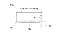
図5は、各ロボットRa,Rb間の相対位置の計測および設定の手順を説明するための図であり、図6は各ロボットRa,Rb間の相対位置の計測および設定を行う際に用いられる突合せ用ツール90を示す側面図である。各ロボットRa,Rbの相対位置関係を維持しながら各ロボットRa,Rbを協調動作させるために、各ロボットRa,Rb間の相対位置関係を計測し、そのデータを双方の制御装置Ca,Cbに登録しておく必要があり、その手順について説明する。
【0053】
各ロボットRa,Rb間の相対位置を計測し、設定するにあたって、各ロボットRa,Rbの手首28には、図6に示される突合せ用ツール90がそれぞれ設けられる。この突合せ用ツール90は、前記手首28にボルトなどのねじ部材によって着脱可能に取り付けられる円板状のフランジ部91と、フランジ部91の中心軸線上に垂直に固定される円形断面を成す棒状部92とを有する。前記棒状部92の先端部分は先細状に形成され、さらに具体的には、円錐台状に形成される。
【0054】
この突合せツール90は、フランジ部91の手首28に接触する表面93から棒状部92の先端部分94までの前記中心軸線方向の長さLが正確にわかっている必要がある。この長さLは、各ロボットRa,Rb間で突き合わせることができる長さに選ばれている。また前記突合せツール90は、円板状のフランジ部91に中心軸線上に棒状部92を垂直に固定した構成であるので、各先端部分94を突合せたときにその他の部位が相互に干渉せず、また周囲に対しても干渉することが防がれる。さらに前記棒状部92の先端部分94は、先細状とされるので、突合せが容易であり、しかも相互に突合せて接触させた状態でずれにくく、またずれた状態では被接触状態となって明確に認識されるため、正確に突合せすることができる。
【0055】
図17は、3点突合せによる各ロボットRa,Rb間座標系の校正手順を説明するための図である。3点突合せによる各ロボットRa,Rbの相対位置の算出方法について説明する。他方のロボットRbの原点Obに関するベース座標系ΣBaseBを、一方のロボットRaのベース座標系ΣBaseAに変換するための変換行列TABと定義する。ここで、変換行列TABは次のような同時変換行列とする。
【0056】
【数1】

一直線上には、任意の3点について突合せを行い、これによって得られるロボットRaベース座標系ΣBaseAにおけるロボットRaのツール先端点の位置と、ロボットRbのベース座標系ΣBaseBにおけるロボットRbのツール先端点の位置とをそれぞれ、点(PA,PB)、点(QA,QB)、点(RA,RB)とする。
【0058】
次に、点PAを原点とし、この点PAから点QAに向かう線分をX軸正方向として、点RAをXY平面(ただし、Y>0)に含むようなロボットRaのベース座標系ΣBaseAにおけるフレームをFAとする。
【0059】
【数2】
同様に、点PBを原点とし、この点PBが点QBに向かう線分をX軸正方向として、点RBをXY平面(ただし、Y>0)に含むようなロボットRBのベース座標系ΣBaseBにおけるフレームをFBとする。
【0061】
【数3】
このとき、フレームFA,FBと変換行列TABとの間には、次式が成り立つ。
FA=TABFB …(12)
したがって、変換行列TABは次式によって求められる。
TAB=FA・FB −1 …(13)
【0063】
このような変換行列TABは、自己(添え字A側)から相手(添え字B側)への座標変換を行なう関数などとして、各制御装置Ca,Cbのメモリ45a,45bに格納される前記プログラムに記載されている。
【0064】
図8は、マスタロボットの動作途中点Miに対応するスレーブロボットの動作途中点Siの算出方法を説明するための図である。まず、一方のロボットRaをマスタロボットとし、他方のロボットRbをスレーブロボットとしたとき、マスタロボットおよびスレーブロボットの共通座標系Σ0において、マスタロボットRaの動作開始点がMs、動作終了点がMeで教示され、また前記共通座標系Σ0においてスレーブロボットRbの動作開始点がSs、動作終了点がSeで教示されたとする。マスタロボットRaの教示点MsからMeへの移動するとき、マスタロボットRaの動作中間点Miに対応するスレーブロボットRbの動作中間点Siを求める。
【0065】
マスタロボットRaの動作途中点Miは、パラメータsを用いて求められる。このパラメータsの値は、s=1のとき、マスタロボットRaが動作開始点Ms到達し、s=0.0のとき動作終了点Meに到達するものとする。また、マスタロボットRaが動作途中点Miにあるときのパラメータsはsiで表し、このときのスレーブロボットRbの動作途中点をSiとする。マスタロボットRaの動作開始点MsからスレーブロボットRbの動作開始点Ssへの変換行列をTAB(s)とし、マスタロボットRaの動作終了点MeからスレーブロボットRbの動作終了点への変換行列をTAB(e)とし、次式で表すものとする。
TAB(s)=Ss・Ms−1 …(14)
TAB(e)=Se・Me−1 …(15)
【0066】
また上記の各変換行列TAB(s)、TAB(e)をXYZオイラー角で表記するとき、TAB(s)は(Xs,Ys,Zs,Os,As,Ts)とし、TAB(e)は(Xe,Ye,Ze,Oe,Ae,Te)として、マスタロボットRaの動作途中点Miに対する変換行列Tiのオイラー角表記を、次式によって求める。
Xi=Xe−(Xe−Xs)・s …(16)
Yi=Ye−(Ye−Ys)・s …(17)
Zi=Ze−(Ze−Zs)・s …(18)
Oi=Oe−(Oe−Os)・s …(19)
Ai=Ae−(Ae−As)・s …(20)
Ti=Te−(Te−Ts)・s …(21)
【0067】
これらの式14〜19を変換行列Tiと表記し、マスタロボットRaの動作途中点Miに対するスレーブロボットRbの動作途中点Siは、
Si=Ti・Mi …(22)
によって求められる。
【0068】
このようなマスタロボットRaの動作途中点Miに対するスレーブロボットRbの動作途中点Siの関係式は、各制御装置Ca,Cbのメモリ45a,45bにプログラムとして格納されており、後述するように、各ロボットRa,Rbのうちで任意にマスタロボットおよびスレーブロボットを設定して、協調動作させることができるように構成されている。
【0069】
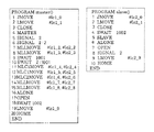
図9は、協調動作部位を教示する手順を説明するための各ロボットRa,Rbのアーム先端部分94a,94bの移動経路を示す斜視図である。同図において実線はマスタロボットのアーム先端部分94aの移動経路を示し、破線はスレーブロボットのアーム先端部分94bの移動経路を示す。図10は、図9に示される各教示点に対応してマスタロボットおよびスレーブロボットを協調動作させるための協調動作プログラムの一例を示す図である。
【0070】
次に、各協調動作のためのプログラムの作成および位置の教示を行う。このプログラムは、一方のロボットRaによって実行されるプログラム「.PROGRAM master( )」と、他方のロボットRbによって実行されるプログラム「.PROGRAM slave( )」とが作成される。
【0071】
一方のロボットRa側に設定されるプログラム「.PRORAM. master( )」は、1〜20のステップを有し、図9の実線で示される動作目標位置Pm0から各目標位置Pm1〜Pm9を経て動作終了位置Pa10に至る動作を、一方のロボットRaに実行させるために、次のように構成される。
【0072】
まず、ステップ1は、一方のロボットRaの各軸を動作開始位置Pm0へ移動させるための動作命令であり、「JMOVE #1c1#0」と入力される。「JMOVE」はロボットを指定した目標位置への各軸の補間動作における移動させるための命令である。「#1c1#0」は動作目標位置Pm0を指示する変数名である。
【0073】
ステップ2は、動作開始位置Pm0から次の目標位置Pm1へ一方のロボットRaを移動させるための命令であり、「LMOVE #1c1#1」と入力される。「LMOVE」は直線動作を指示する予約語であり、「#1c1#1」は目標位置Pm1を指示する変数名である。
【0074】
ステップ3は、前記ステップ2で指定した位置Pm1でハンド30を閉じさせるための命令であり、「CLOSE」と記載される。以上がマスタロボットRaの単独動作のプログラムである。
【0075】
次に、ステップ4は、協調動作を宣言する命令であり、「MASTER」と記載される。この命令によって、一方のロボットRaがマスタロボットに設定され、他方のロボットRb側でのスレーブ宣言されて、協調動作が開始する。マスタ機能実行モードの制御装置Caが指令を送信して、これをスレーブ機能実行モードの制御装置Cbが受信するまでには、通信による遅れが発生するが、スレーブ機能実行モードの制御装置Cbの最小割込み周期Ts(b)を、マスタ機能実行モードの制御装置Caからの指令がスレーブ機能実行モードの制御装置Cbに、たとえば上記のように3カウント未満で入力されたときには、最小割込み周期Ts(b)を短くし、5カウントを超えて入力されたときには、最小割込み周期Ts(b)を長くするとともに、マスタ機能実行モードの制御装置Caの自己のマスタロボットRaへの制御時刻ta11,ta12,ta13,…を、予め定める時間Tだけ遅延させて送信することによって、マスタロボットRaに対するスレーブロボットRbの動作の遅れを防止し、各ロボットを高精度で同期させて、協調動作させることができる。
【0076】
ステップ5は、マスタロボットRaに対してハンド30を閉じるための命令であり、「SIGNAL 2」と記載される。
【0077】
ステップ6は、スレーブロボットRbのハンド30を閉じるための命令であり、「SIGNAL 2:2」と記載される。
【0078】
ステップ7は、各ロボットRa,Rbを協調動作させながら次の目標位置Pm2,Ps2へ移動させるための命令であり、「MLLMOVE #1c2#2,#1c2#2」と記載される。
【0079】
ステップ8は、各ロボットRa,Rbを次の目標位置Pm3,Ps3へ移動させるための命令であり、「MLLMOVE #1c1#3,#1c2#3」と記載される。
【0080】
ステップ9は、マスタロボットRaを次の指令を満足するまで待機させるための命令であり、「SWAIT 1001」と記載される。
【0081】
ステップ10は、スレーブロボットRbを入出力回路48bに次の指令を入力するまで待機させるための命令であり、「SWAI 2:1001」と記載される。
【0082】
ステップ11は、各ロボットRa,Rbを次の目標位置Pm4,Ps4へ移動させるための命令であり、「MLC1MOVE #1c1#4,#1c2#4」と記載される。
【0083】
ステップ12は、各ロボットRa,Rbを次の目標位置Pm5,Ps5へ移動させるための命令であり、「MLC1MOVE #1c1#5,#1c2#5」と記載される。
【0084】
ステップ13は、各ロボットRa,Rbを次の目標位置Pm6,Ps6へ移動させるための命令であり、「MLC2MOVE #1c1#6,#1c2#6」と記載される。
【0085】
ステップ14は、各ロボットRa,Rbを次の目標位置Pm7,Ps7へ移動させるための命令であり、「MLLMOVE #1c1#7,#1c2#7」と記載される。
【0086】
ステップ15は、各ロボットRa,Rbを次の目標位置Pm8,Ps8へ移動させるための命令であり、「MLLMOVE#1c1#8,#1c2#8」と記載される。
【0087】
ステップ16は、マスタロボットRaの協調動作を解除するための命令であり、「ALONE」と記載される。
【0088】
ステップ17は、一方のロボットRaのハンド30を開くための命令であり、「OPEN」と記載される。
【0089】
ステップ18は、一方のロボットRaに対して、タイマが変数名「1002」で指示された状態を満足するまで待機させるための命令であり、「SWAIT 1002」と記載される。
【0090】
ステップ19は、一方のロボットRaを変数名「#1c1#9」で指示させるも目標位置Pm9へ直線移動させるための命令であり、「LMOVE #1c1#9」と記載される。
【0091】
ステップ20は、一方のロボットRaを動作終了位置Pm10へ移動させるための命令であり、「HOME」と記載される。
【0092】
次に、他方のロボットRbに対して設定されるプログラムについて説明する。この他方のロボットRb用プログラム「.PRORAM slave( )」は、1〜10のステップを有し、図9の破線で示される動作目標位置Ps0から各位置Ps1〜Ps9を経て動作終了位置Ps10に至る動作を、スレーブロボットRbに実行させるために、次のように構成される。
【0093】
まず、ステップ1は、他方のロボットRaの各軸を動作目標位置Ps0へ移動させるための動作命令であり、「JMOVE #1c1#0」と入力される。「JMOVE」はロボットを指定した位置への補間動作における移動させるための命令である。「#1c1#0」は動作目標位置Ps0の座標である。
【0094】
ステップ2は、動作開始位置Ps0から次の位置Ps1へ他方のロボットRbを移動させるための命令であり、「LMOVE #1c1#1」と記載される。「LMOVE」は直線動作命令であり、「#1c1#1」は次の位置Ps1の座標である。
【0095】
ステップ3は、前記ステップ2で指定した位置Ps1でハンド30を閉じさせるための命令であり、「CLOSE」と記載される。以上がスレーブロボットの単独動作のプログラムである。
【0096】
次に、ステップ4は、他方のロボットRbを変数名「1002」で指示される条件を満足するまで待機させるための命令であり、「SWAIT 1002」と記載される。
【0097】
ステップ5は、自己がスレーブロボットとして動作することを宣言するための命令であり、「SLAVE」と記載される。このプログラムの実行時においては、スレーブロボットRbは、マスタロボットRa側からの各ステップ5〜15の命令に応答して協調動作を行う。この協調動作時は、前述したように、他方のロボットRbはネットワーク通信接続手段21によって一方のロボットRaに接続されるので、制御周期のずれを修正しながら相互に正確に同期して協調動作させることができる。
【0098】
ステップ6は、協調動作を解除し、単独動作に戻ったことを宣言するための命令であり、「ALONE」と記載される。
【0099】
ステップ7は、他方のロボットRbのハンド30を開くための命令であり、「OPEN」と記載される。
【0100】
ステップ8は、マスタロボットRaおよびスレーブロボットRbの双方に対して指令を個別に設定するための命令であり、「SIGNAL 2」と記載される。
【0101】
ステップ9は、他方のロボットRbを変数名「#1c2#9」で指示される目標位置Ps9へ移動させるための命令であり、「LMOVE #1c2#9」と記載される。
【0102】
ステップ10は、他方のロボットRbを動作終了位置Ps10へ移動させるための命令であり、「HOME」と記載される。
【0103】
このようにして各ロボットが実行する一連の作業のうちで、協調動作する行程については、各ロボットをマスタロボットとスレーブロボットとに設定して、前記通信接続手段を介して相互に通信し、高精度で同期させて協調動作させることができる。
【0104】
またスレーブ機能実行モードの制御装置Cbは、入力手段から動作指令を入力すると、この動作指令は、通信接続手段を介してマスタ機能実行モードの制御装置Caに入力される。このマスタ機能実行モードの制御装置Caは、入力した動作指令に応答して制御動作を実行し、こうしてスレーブ側制御装置Cbからの動作指令の入力によって、マスタロボットRaを制御することができる。したがってオペレータは、マスタ側制御装置Caからだけではなく、スレーブ側制御装置Cb側からも動作指令を入力して、場所的にスレーブロボットRbから離れた位置に設置されているマスタロボットRaの動作を設定することができ、したがって協調制御システム全体を操作者の希望する場所から操作することが可能となり、操作上の利便性が向上される。
【0105】
さらにスレーブ機能実行モードの制御装置Cbによって制御されるロボットRaに接続されたエンドエフェクタなどの外部機器は、スレーブ機能実行モードに設定された制御装置Cbの入出力回路(略称IO)48bを用いて行なわれる。協調動作においては、マスタロボット側のメモリ45aに記憶されたプログラムの動作命令にしたがって動作するため、スレーブロボットRbに接続された外部機器の制御は、マスタロボットRaの制御装置Caに設けられる入出力回路48aを用いて行なわれ、そのために信号の配線が煩雑になり、スレーブロボットRbを単独で使用しようとした場合に、マスタロボットRaの信号の影響を受けてしまう。このような不具合は、上記のようにマスタロボットRaがスレーブ側制御装置Cbの入出力回路48aを用いることによって、回避することができる。
【0106】
上述の実施の形態では、2台のロボットRa,Rbに個別に設けられる2台の制御装置Ca,Cbを通信接続手段21によって接続した構成について述べたが、本発明の実施の他の形態では、3台以上のロボットに個別に設けられる制御装置を通信接続手段によって接続して協調制御する構成に対しても、本発明を好適に実施することができ、高精度で各制御装置を同期させて、協調動作させることができる。
【0107】
【発明の効果】
請求項1記載の本発明によれば、単独機能実行モード、マスタ機能実行モードおよびスレーブ機能実行モードのいずれか1つをプログラム上の命令として設定しておくことによって、各ロボットをマスタロボットとスレーブロボットとに設定して、高精度で同期させて協調動作させることができる。
【0108】
また、マスタ側制御装置が動作指令を送信した時刻taから、スレーブ側制御装置が前記動作指令を受信して自己のロボットの制御を開始する時刻tbまでの通信遅れ時間(tb−ta)が予め定める時間Tとなるように、最小割込み周期を変化させるので、スレーブ側制御装置が自己のロボットに対する制御を開始する時刻tbが、前記マスタ側制御装置がマスタ側制御装置に対して動作指令を送信した時刻taに対して、前記予め定める時間Tよりも長くなる方向および予め定める時間Tよりも短くなる方向に大きくずれることが防がれる。
【0109】
請求項2記載の本発明によれば、前記予め定める時間間隔Tが各制御装置の制御周期W以下に選ばれるので、マスタ側制御装置から動作指令が送信される時刻taから、スレーブ側制御装置によって受信されて、このスレーブ側制御装置が自己のロボットの制御を開始する時刻tbまでの時間(tb−ta)が、制御周期Wを超えてしまうことが防がれる。これによってスレーブ側制御装置は、スレーブ側制御装置の1制御周期Wの時間内に、マスタ側制御装置から複数の動作指令を受信してしまうという不具合が発生を確実に防止し、マスタロボットとスレーブロボットとを高精度で協調動作させることが可能となる。
【0110】
請求項3記載の本発明によれば、マスタ機能実行モードの制御装置の指令値をスレ−ブ機能実行モードの制御装置の通信遅れ時間だけ遅延することによって、マスタロボットに対するスレーブロボットの動作の遅れを防止し、各ロボットを高精度で同期させて、協調動作させることができる。
【0111】
請求項4記載の本発明によれば、スレーブ機能実行モードの制御装置は、入力手段から動作指令を入力すると、この動作指令は、通信接続手段を介してマスタ機能実行モードの制御装置に入力される。このマスタ機能実行モードの制御装置は、入力した動作指令に応答して制御動作を実行し、こうしてスレーブ側制御装置からの動作指令の入力によって、マスタロボットを制御することができる。したがってオペレータは、マスタ側制御装置からだけではなく、スレーブ側制御装置側からも動作指令を入力して、場所的にマスタロボットから離れた位置に設置されているマスタロボットの動作を設定することができ、操作上の利便性が向上される。
【0112】
請求項5記載の本発明によれば、協調動作においては、マスタロボットのプログラムの動作命令にしたがって動作するため、スレーブロボットの信号の出入力は、マスタロボットの制御装置に設けられる入出力装置を用いて行なわれ、そのために信号の配線が煩雑になり、スレーブロボットを単独で使用しようとした場合に、マスタロボットの信号の影響を受けてしまうという不具合を、マスタロボットがスレーブ側制御装置の入出力装置を用いることによって、回避することができる。
【0113】
請求項6記載の本発明によれば、各制御装置には緊急停止手段が備えられるので、どの位置のロボットからでも、異常が発生したときに、前記緊急停止手段を用いて各ロボットの一部または全体を緊急停止させることができ、これによって安全性が向上される。
【0114】
請求項7記載の本発明によれば、マスタ座標系に設定された共通な3点を結ぶ仮想フレームを基準にして協調動作するので、各制御装置は、各ロボットの位置および姿勢、さらには位置および姿勢のずれを、常に共通な座標系上で各ロボットが相対的位置を正確に認識可能とし、各ロボットのいずれのロボットをマスタとして設定しかつスレーブとして設定しても、1つの座標系内で協調動作を高精度で制御することができる。
【0115】
請求項8記載の本発明によれば、マスタロボットとスレーブロボットとが実際の相対位置関係と設定された相対位置変換行列との間にずれがある場合、ツールの寸法に誤差がある場合、ロボットリンク長のばらつきがある場合、ゼロイング精度とも呼ばれるロボットの基準位置への設置精度自体にばらつきがある場合、ならびに負荷によるロボットアームのたわみの影響によって、相対的な位置および姿勢関係を一定に保つように制御しても、実際の位置および姿勢関係が一定に保たれない場合などの相対位置がずれる原因が存在しても、上記のようにマスタ機能実行モードに設定されたロボットの教示位置の他に、スレーブ機能実行モードに設定されるロボットの位置をも教示することによって、相対位置および姿勢を変更しながらスレーブロボットをマスタロボットに追従させて協調動作させることが可能となる。これによってマスタおよびスレーブの各ロボットの相対位置および姿勢のずれが時間経過とともに拡大することが防がれ、相対位置および姿勢関係を高精度に維持しながら、所定の動作を継続的に実行することができる。
【図面の簡単な説明】
【図1】本発明の実施の一形態のロボットの協調制御システム20の全体の構成を示す系統図である。
【図2】各制御装置Ca,Cbの構成を示すブロック図である。
【図3】各制御装置Ca,Cbのソフトウェア上の構成を示すブロック図である。
【図4】各制御装置Ca,Cbを同期させるためのソフトウェアプログラムの構成を示す簡略化したブロック図である。
【図5】各ロボットRa,Rb間の相対位置の計測および設定の手順を説明するための図である。
【図6】各ロボットRa,Rb間の相対位置の計測および設定を行う際に用いられる突合せ用ツール90を示す側面図である。
【図7】3点突合せによる各ロボットRa,Rb間座標系の校正手順を説明するための図である。
【図8】マスタロボットの動作途中点Miに対応するスレーブロボットの動作途中点Siの算出方法を説明するための図である。
【図9】協調動作部位を教示する手順を説明するための各ロボットRa,Rbのアーム先端部分94a,94bの移動経路を示す斜視図である。
【図10】図9に示される各教示点に対応してマスタロボットおよびスレーブロボットを協調動作させるための協調動作プログラムの一例を示す図である。
【図11】従来の技術のロボットの協調制御システムのマスタロボットおよびスレーブロボットの各制御装置を同期させるためのソフトウェアプログラム上の構成の一部を示すブロック図である。
【図12】他の従来の技術の協調制御システムに用いられる割込み方式によって各制御装置を同期させるソフトウェアプログラム上の手法を説明するためのブロック図である。
【符号の説明】
20 ロボットの協調制御システム
21 通信接続手段
22 床
23 基台
24 旋回体
25,26,27 アーム
28 手首
29 ワーク
30 ハンド
31a,31b;35a,35b ライン
33a,33b 制御装置本体
37a,37b 教示入力手段
41a,41b サーボ駆動手段
42a,42b パワーシーケンス回路
43a,43b 操作パネル
44a,44b 制御手段
45a,45b メモリ
46a,46b 教示入力手段用インターフェイス回路
47a,47b パーソナルコンピュータ用インターフェイス回路
48a,48b 入出力回路
49a,49b 通信制御手段
50a,50b バスライン
51 ハブ
52a,52b 通信ケーブル
53a,53b
61a,61b プログラム格納部
62a,62b プログラム解釈実行部
63a,63b スレーブ指令値生成部
64a,64b 動作指令値生成部
65a,65b 指令値送信部
67a,67b 指令値受信部
68a,68b 割込み処理部
69a,69b クロック発生部
Ca,Cb 制御装置
Ra,Rb ロボット
SW1,SW2 停止スイッチ
SW3,SW4 ハンド開閉検出スイッチ
SW5,SW6 緊急停止スイッチ[0001]
TECHNICAL FIELD OF THE INVENTION
The present invention relates to a robot cooperative control system that connects control devices, which are also called robot controllers provided for a plurality of robots, via a communication network and causes the robots to perform a cooperative operation.
[0002]
[Prior art]
Conventionally, when a workpiece is a heavy or large object, a plurality of teaching points and a plurality of teaching points from a preset starting point to a reaching point are maintained by a plurality of robots while maintaining a state in which the workpiece is securely held. 2. Description of the Related Art A cooperative control system that cooperates and controls each robot is used to realize a cooperative operation of accurately and stably transferring a robot through an interpolation point between points.
[0003]
In such a cooperative control system using a plurality of robots, the work can be gripped at a plurality of positions according to the arrangement position of the robot in the work space. Transport is possible. Further, even if the work is a heavy object, the weight of the work is distributed to a plurality of robots, so that the weight load and the inertial load of each robot are small, and the transfer speed can be increased to shorten the transfer time. .
[0004]
The cooperative control system includes a “many-to-one” system in which a plurality of robots are integrally controlled by one control device, and a “1: 1” system in which a control device corresponding to each robot is individually provided. There is a system. In a "many-to-one" system in which a plurality of robots are controlled by a single control device, since a single control device must control a plurality of robots, the control device has a special configuration. Become.
[0005]
On the other hand, in a “1: 1” system in which a control device is provided for each of a plurality of robots and each robot is individually controlled, one robot is controlled by one control device. It is not necessary to use a control device having a special configuration as in the system of "1", and a general-purpose control device can be used. Therefore, as compared with a “many: 1” system, a cooperative control system can be easily realized by introducing a cooperative control program, which is excellent in easiness of realization.
[0006]
Moreover, the general-purpose control device can be used alone for other purposes without constructing a cooperative control system, so that the cost of purchasing the control device can be saved and the advantage is that it is economical. Have. Furthermore, since the number of robots can be freely changed, it is possible to freely cope with the system design, and there is an advantage that the degree of freedom in system design is high.
[0007]
In still another conventional technique, in a “1: 1” individual cooperative control system in which a control device is individually provided for a plurality of robots, a program is created for each robot, and a transfer operation is performed using an interlock. The individual control system to be controlled and one of the plurality of robots are set as master robots, and other robots except the master robot are set as slave robots that follow in synchronization with the master robot, and 2. Description of the Related Art A master / slave cooperative control system that conveys a work by cooperatively controlling a master robot and a slave robot by a software program mounted on the master robot is well known.
[0008]
In the above-described master / slave cooperative control system, when it is necessary to change the operation of the robot due to a change in the work and a change in the transfer condition, only the program mounted on the master robot needs to be changed. It has the advantage of being easy to modify, create and manage. Therefore, one master control device is selected from a plurality of control devices realized by the general-purpose robot controller, and one or more remaining slave control devices are operated in cooperation.
[0009]
In such a system that performs cooperative control between a master and a slave, when data is transmitted and received between each control device connected by a bus connection or a communication line, a control system is independently configured for each robot. Each of the control devices must be synchronized with each other. As a method for achieving this synchronization, when each control device is bus-coupled and data is transmitted and received between the control devices according to the shared memory method, a method of providing a flag on the shared memory and an interrupt are used. There is a method of generating an event in interrupt processing.
[0010]
FIG. 11 is a block diagram showing a part of a configuration on a software program for synchronizing the control devices A and B of the master robot and the slave robot in the conventional master / slave cooperative control system. According to this conventional technique, in order to synchronize the control devices A and B by a shared memory system, a master control device A for controlling a master robot and a slave control device B for controlling a slave robot are described as follows. The
[0011]
FIG. 12 is a block diagram for explaining a method of synchronizing the control devices A and B by an interrupt method used in another conventional master / slave cooperative control system. When an interrupt command from the
[0012]
Still another conventional technique is disclosed in Japanese Patent Application Laid-Open No. 7-20915. In this conventional technology, two robots having an arm to be controlled in a cooperative operation and a control device for individually controlling each robot are provided, and one of the robots is set as a master robot, and the other is set as a master robot. A robot cooperative control system that cooperatively controls a robot as a slave robot is disclosed.
[0013]
Each control device performs an interpolation calculation based on the teaching point data, determines a passing point to which the arm of the master robot should move, and determines a next passing point of the arm of the slave robot, where the arm of the master robot moves next. The determination is made in any one of the control devices based on the power point and the relative position and posture relationship between the two arms corresponding to the state of the work being transported. The master-side controller determines the next passing point of the arm according to the given teaching content, transmits the data to the slave-side controller, and determines the next passing point of the arm of the slave robot. These control devices are connected by a communication line for transmitting and receiving data to and from each other as described above. In addition, in order to achieve synchronization, all data and programs necessary for cooperative operation are controlled by using a clock signal from a clock oscillation circuit built in a CPU (Central Processing Unit) of each control device for synchronization. Are stored in a memory of a control device common to the master robot and the slave robot.
[0014]
[Problems to be solved by the invention]
In each of the conventional techniques shown in FIGS. 11 and 12, there is a problem that the other control device B generates useless waiting time such as polling for a flag and waiting for an event. In the prior art disclosed in the above-mentioned Japanese Patent Application Laid-Open No. 7-20915, when synchronizing the control devices in order to make the master arm and the slave arm cooperate, a small difference between the synchronization signals of the control devices is required. Since no specific measures are taken to eliminate the deviation of the control cycle due to the accumulation of a small difference between the transmission cycle and the reception cycle, and the unavoidable communication delay due to the communication line, it is necessary to always synchronize multiple control devices. There is a problem that it can not be maintained in the state where it was. Furthermore, there are errors in the method of inputting an operation command from the input means provided in each control means provided for each robot, the method of transmitting and receiving signals between input / output means of each robot, and the setting of the relative position of each robot. Since no consideration is given to how to deal with the situation when it occurs, it is practically impossible to construct a cooperative control system.
[0015]
SUMMARY OF THE INVENTION An object of the present invention is to provide a robot cooperative control system capable of eliminating a synchronization deviation between a plurality of control devices and preventing a deviation of a cooperative operation of each robot.
[0016]
[Means for Solving the Problems]
The present invention according to
Communication connection means for connecting each control device so as to be able to communicate with each other to form a network;
Input means provided for each control device and for inputting an operation command of each robot;
Storage means provided in each control device and storing a program for operating each robot in response to an operation command of each robot;
Timing signal generating means provided for each control device and generating a timing signal at the minimum interrupt cycle,
Each control device can selectively execute at least one of a single function execution mode, a master function execution mode, and a slave function execution mode by a program stored in the storage means,
When one of the control devices is set to the master function execution mode by executing the program, at least one of the remaining control devices of the control devices excluding the control device set to the master function execution mode is set. One is set to a slave function execution mode for executing a slave operation by executing the program,
The control device set in the slave function execution mode, the control device in the slave function execution mode receives the operation command from the time ta when the control device in the master function execution mode has transmitted the operation command, and controls the robot of its own. The minimum interrupt cycle Ts (b) of the control device set to the slave function execution mode is changed so that the communication delay time (tb-ta) until the start time tb becomes a predetermined time T,
A robot cooperative control system characterized in that a master robot controlled by a control device set in a master function execution mode and a slave robot controlled by a control device set in a slave function execution mode cooperate. It is.
[0017]
According to the present invention, a control device is provided for each of the plurality of robots, and each control device individually controls the operation of each robot in synchronization with a timing signal generated at a predetermined minimum interrupt cycle from the timing signal generation means. To control. Each control device is communicably connected to each other by communication connection means, and a communication network is established between the control devices. Each control device is provided with an input means, and can input teaching data and the like necessary for performing independent operation and cooperative operation of each robot. In the storage means, a program for operating each robot in response to an operation command predetermined for each robot is stored. By executing this program, each control device can execute the single function execution mode, the master function execution mode, and the slave function execution mode. When one of the control devices is selectively set to the function execution mode and one control device is set to the master function execution mode, all or some of the remaining control devices are set to the slave function execution mode.
[0018]
As described above, each of the control devices can selectively set any one of the single function execution mode, the master function execution mode, and the slave function execution mode by the program. By describing the robot control device, the robot control device to be operated as a slave, and the robot control device to be operated independently as instructions on a program, the selected control device becomes a master that executes the master operation. Set to execution mode. In addition, by selecting some or all of the remaining control devices to be slave-operated, specifically by setting them as instructions on a program, the selected control device executes the slave operation. Slave execution mode.
[0019]
Among the series of operations performed by each robot in this manner, for the step of performing a cooperative operation, each robot is set as a master robot and a slave robot, and communicates with each other via the communication connection means. Synchronous operation can be performed in synchronization with accuracy.
[0021]
Also,The control device in the slave function execution mode starts from the time ta at which the control device in the master function execution mode transmits the operation command to the time at which the control device in the slave function execution mode receives the operation command and starts controlling its own robot. Since the minimum interrupt cycle is changed so that the communication delay time (tb-ta) until tb becomes a predetermined time T, the time tb at which the slave-side control device starts control of its own robot is determined by the master-side control. With respect to the time ta at which the device has transmitted the operation command to the master-side control device, it is possible to prevent a large deviation in a direction longer than the predetermined time T and in a direction shorter than the predetermined time T. As a result, it is possible to limit the time lag in the operation of the slave robot with respect to the master robot, and to allow the robots to cooperate accurately.
[0022]
Claim2SUMMARY OF THE INVENTION1In the robot cooperative control system described above, the predetermined time T is selected to be equal to or less than a control cycle W of each control device.
[0023]
According to the present invention, since the predetermined time T is selected to be equal to or less than the control cycle W of each control device, the time T is received by the slave control device from the time ta when the operation command is transmitted from the master control device. It is possible to prevent the time (tb-ta) until the time tb at which the slave-side control device starts control of its own robot from exceeding the control cycle W. As a result, the slave-side control device reliably prevents a problem of receiving a plurality of operation commands from the master-side control device within one control cycle W of the slave-side control device. It is possible to perform a cooperative operation with the robot with high accuracy.
[0024]
Claim3SUMMARY OF THE INVENTION2In the robot cooperative control system described above, the control device set in the master function execution mode transmits a command to the robot to be controlled by the master device to the communication delay time (tb-t) with respect to the control device in the slave function execution mode. The transmission is delayed by ta).
[0025]
According to the present invention, there is a communication delay time (tb-ta) between the time when the control device in the master function execution mode transmits a command and the time when the control device in the slave function execution mode receives the command. An operational shift occurs between the robot and the slave robot. To prevent this, a command to the robot controlled by the control device in the master function execution mode is transmitted by delaying the communication delay time (tb-ta) of the control device in the slave function execution mode. In addition, it is possible to prevent the delay of the operation of the slave robot with respect to the master robot without changing the settings of the entire system, and to synchronize the robots with high accuracy to perform the cooperative operation.
[0026]
Claim4The present invention described in
[0027]
According to the present invention, when the control device in the slave function execution mode inputs an operation command from the input means, the operation command is input to the control device in the master function execution mode via the communication connection means. The control device in the master function execution mode executes the control operation in response to the input operation command, and thus can control the master robot by inputting the operation command from the slave control device. Therefore, the operator can input an operation command not only from the master-side control device but also from the slave-side control device to set the operation of the master robot installed at a position distant from the slave robot in place. Therefore, it is possible to operate the entire cooperative control system from a place desired by the operator, and the operational convenience is improved.
[0028]
Claim5The present invention described in
[0029]
According to the present invention, an external device such as an end effector connected to a robot controlled by the control device in the slave function execution mode uses an input / output device (abbreviated as IO) of the control means set in the slave function execution mode. It is done. In the cooperative operation, since the operation is performed in accordance with the operation instruction of the program stored in the storage means on the master robot side, the control of the external devices connected to the slave robot uses an input / output device provided in the control device of the master robot. Therefore, the signal wiring becomes complicated, and when the slave robot is used alone, it is affected by the signal of the master robot. Such a problem can be avoided by the master robot using the input / output device of the slave-side control device as described above.
[0030]
Claim6The present invention described in
[0031]
According to the present invention, since each control device is provided with an emergency stop means, when an abnormality occurs from any of the robots, a part or the whole of each robot is emergency stopped using the emergency stop means. And thereby improve safety.
[0032]
Claim7The present invention described in
[0033]
According to the present invention, since the cooperative operation is performed based on a virtual frame connecting three common points set in the master coordinate system, each control device determines the position and posture of each robot, and further, the deviation of the position and posture. , Each robot can always accurately recognize the relative position on a common coordinate system, and even if any of the robots is set as a master and set as a slave, coordination within one coordinate system The operation can be controlled with high accuracy.
[0034]
Claim8SUMMARY OF THE INVENTION7In the robot cooperative control system described in the above, in the cooperative operation, a relative position of the robot set in the slave function execution mode with respect to the robot set in the master function execution mode is a relative position at a taught operation start point. It is characterized in that interpolation is performed so as to satisfy the positional relationship and the relative positional relationship at the taught operation end point.
[0035]
According to the present invention, when there is a deviation between the actual relative positional relationship between the master robot and the slave robot and the set relative position conversion matrix in the relative positional relationship between the master and slave robots, The relative position may vary due to dimensional errors, variations in the robot link length, variations in the accuracy of the robot installation at the reference position, also known as zeroing accuracy, and the effect of the deflection of the robot arm due to the load. Even if the actual position and posture relationship are not kept constant even if there is a cause of relative position deviation even if control is performed so that the posture relationship is kept constant, the master function execution mode is set as described above. By teaching the robot position set in the slave function execution mode in addition to the robot teaching position Te, it becomes possible to cooperate with the slave robot to follow the master robot while changing the relative position and orientation. This prevents the deviation of the relative position and posture of each of the master and slave robots from expanding over time, and continuously performs a predetermined operation while maintaining the relative position and posture relationship with high accuracy. Can be.
[0036]
BEST MODE FOR CARRYING OUT THE INVENTION
FIG. 1 is a system diagram showing an overall configuration of a robot
[0037]
As an example, each of the robots Ra and Rb is provided with a revolving
[0038]
Each of the control devices Ca and Cb is also called a robot controller, and is mutually connected by the communication connection means 21 to form a communication network. These control devices Ca and Cb are also called
[0039]
The
[0040]
FIG. 2 is a block diagram illustrating a configuration of each of the control devices Ca and Cb. Each of the control devices Ca and Cb operates servo driving means 41a and 41b for driving a servo motor (not shown) provided in each of the robots Ra and Rb,
[0041]
The
[0042]
The communication connection means 21 includes a hub (HUB) 51, communication control means 49a and 49b provided in each of the control devices Ca and Cb, and
[0043]
FIG. 3 is a block diagram illustrating a software configuration of each of the control devices Ca and Cb. The control devices Ca and Cb execute the programs stored in the
[0044]
Each of the control devices Ca and Cb is set to one of a single function execution mode, a master function execution mode, and a slave function execution mode by a program stored in the
[0045]
FIG. 4 is a diagram for explaining the synchronization processing function of each of the control devices Ca and Cb. Each of the control devices Ca and Cb has the same synchronization processing function. For convenience, one control device Ca set to the master function execution mode is set as a transmission side, and the other control device set to the slave function execution mode is used. The device Cb will be described as a receiving side. The command signal transmitted from the one control device Ca at each of the times ta1, ta2, ta3,... At a predetermined control cycle W is transmitted to the other control device Cb via the communication connection means 21 to control the previous slave robot Rb. Are received in time series at the respective times (tb0 + Δt1), (tb1 + Δt2), (tb2 + Δt3),... After a lapse of a predetermined time Δt1, Δt2, Δt3,.
[0046]
In such transmission of the operation command from the master-side control device Ca to the slave-side control device Cb via the communication connection means 21, the crystal oscillator built in the control means 44a, 44b (abbreviated CPU) of each of the control devices Ca, Cb. , A first communication delay time with respect to the transmission times ta1, ta2, ta3,... Of the reception times (tb0 + Δt1), (tb1 + Δt2), (tb2 + Δt3),. , And the slave-side control device Cb receives the operation commands 1, 2, 3,... From the master-side control device Ca at reception times (tb0 + Δt1), (tb1 + Δt2), (tb2 + Δt3),. From the control time tb1, tb2, tb3,... At which the control of the slave robot Rb is started. 2, there is a difference between the operation of the master robot Ra controlled by the one control device Ca and the operation of the slave robot Rb controlled by the other control device Cb. The relative position shift between the robots Ra and Rb at the same time cannot be ignored in terms of work accuracy.
[0047]
In FIG. 4, when the master side (transmission side) control device Ca transmits the
[0048]
Next, at time ta2 after one control cycle has elapsed, master-side control device Ca transmits
[0049]
The
[0050]
In this way, the slave-side control device Cb is received by the slave-side control device Cb from the times ta1, ta2, ta3,... At which the
[0051]
Further, in order to completely synchronize the master-side control device Ca and the slave-side control device Cb, the communication delay time due to the communication via the communication connection means 21 and the operation of the slave-side control device Cb from the master-side control device Ca Are received at the reception times (tb0 + .DELTA.t1), (tb1 + .DELTA.t2), (tb2 + .DELTA.t3),... And the time lag from the control time tb1, tb2, tb3,. It is necessary to eliminate the second communication delay. Therefore, in order to eliminate the first communication delay, n times (for example, n = 8) of the minimum interrupt period Ts (b) of the slave side (or reception side) control device Cb controlled as described above is controlled by the control. When the period corresponds to the cycle W, the control times ta11, ta12, ta13,... On the master side need to match the control times tb1, tb2, tb3,. Therefore, the master-side control device Ca transmits the control times ta11, ta12, ta13,... To the robot Ra generated by the command
[0052]
FIG. 5 is a diagram for explaining the procedure for measuring and setting the relative position between the robots Ra and Rb. FIG. 6 is used when measuring and setting the relative position between the robots Ra and Rb. It is a side view which shows the
[0053]
In measuring and setting the relative position between the robots Ra and Rb, a butting
[0054]
The butting
[0055]
FIG. 17 is a diagram for explaining a calibration procedure of the coordinate system between the robots Ra and Rb by three-point matching. A method of calculating the relative positions of the robots Ra and Rb by three-point matching will be described. A transformation matrix T for transforming the base coordinate system ΣBaseB regarding the origin Ob of the other robot Rb into the base coordinate system ΣBaseA of the one robot RaABIs defined. Here, the transformation matrix TABIs a simultaneous transformation matrix as follows.
[0056]
(Equation 1)
On the straight line, three arbitrary points are compared, and the position of the tool tip of the robot Ra in the robot Ra base coordinate system ΣBaseA obtained by this and the tool tip of the robot Rb in the base coordinate system ロ ボ ッ ト BaseB of the robot Rb are obtained. The position and the point (PA, PB), Point (QA, QB), Point (RA, RB).
[0058]
Next, point PAAnd the point PAFrom point QAThe line segment towardAIs defined in the base coordinate system ΣBaseA of the robot Ra so as to include F in the XY plane (where Y> 0).AAnd
[0059]
(Equation 2)
Similarly, point PBAnd the point PBIs point QBThe line segment towardBRobot R that includes in the XY plane (where Y> 0)BFrame in the base coordinate system ΣBaseB of FBAnd
[0061]
(Equation 3)
At this time, the frame FA, FBAnd the transformation matrix TABThe following equation is established between and.
FA= TABFB … (12)
Therefore, the transformation matrix TABIs obtained by the following equation.
TAB= FA・ FB -1 … (13)
[0063]
Such a transformation matrix TABIs described in the program stored in the
[0064]
FIG. 8 is a diagram for explaining a method of calculating the halfway point Si of the slave robot corresponding to the halfway point Mi of the master robot. First, when one robot Ra is a master robot and the other robot Rb is a slave robot, in the common coordinate system # 0 of the master robot and the slave robot, the operation start point of the master robot Ra is Ms, and the operation end point is Me. It is assumed that the operation is started and the operation end point of the slave robot Rb is taught in Ss and Se in the common coordinate system # 0. When the master robot Ra moves from the teaching point Ms to Me, an operation intermediate point Si of the slave robot Rb corresponding to the operation intermediate point Mi of the master robot Ra is obtained.
[0065]
The operation midpoint Mi of the master robot Ra is obtained using the parameter s. It is assumed that when s = 1, the master robot Ra reaches the operation start point Ms, and when s = 0.0, the parameter s reaches the operation end point Me. The parameter s when the master robot Ra is at the midway point Mi is represented by si, and the midway point of the slave robot Rb at this time is Si. The transformation matrix from the operation start point Ms of the master robot Ra to the operation start point Ss of the slave robot Rb is represented by TAB(S), and the conversion matrix from the operation end point Me of the master robot Ra to the operation end point of the slave robot Rb is TAB(E) and expressed by the following equation.
TAB(S) = Ss · Ms-1 … (14)
TAB(E) = Se ・ Me-1 … (15)
[0066]
Further, each of the above transformation matrices TAB(S), TABWhen (e) is expressed in XYZ Euler angles, TAB(S) is (Xs, Ys, Zs, Os, As, Ts), and TABIn (e), as (Xe, Ye, Ze, Oe, Ae, Te), the Euler angle notation of the transformation matrix Ti with respect to the operation midpoint Mi of the master robot Ra is obtained by the following equation.
Xi = Xe− (Xe−Xs) · s (16)
Yi = Ye− (Ye−Ys) · s (17)
Zi = Ze- (Ze-Zs) · s (18)
Oi = Oe- (Oe-Os) · s (19)
Ai = Ae− (Ae−As) · s (20)
Ti = Te− (Te−Ts) · s (21)
[0067]
These
Si = Ti · Mi (22)
Required by
[0068]
The relational expression of such an operation halfway point Si of the slave robot Rb with respect to the operation halfway point Mi of the master robot Ra is stored as a program in the
[0069]
FIG. 9 is a perspective view showing the movement path of the arm tip portions 94a and 94b of the robots Ra and Rb for explaining the procedure for teaching the cooperative operation parts. In the figure, the solid line indicates the movement path of the arm tip 94a of the master robot, and the broken line indicates the movement path of the arm tip 94b of the slave robot. FIG. 10 is a diagram showing an example of a cooperative operation program for causing the master robot and the slave robot to cooperate with each other corresponding to each teaching point shown in FIG.
[0070]
Next, a program for each cooperative operation is created and the position is taught. As this program, a program “.PROGRAM master ()” executed by one robot Ra and a program “.PROGRAM slave ()” executed by the other robot Rb are created.
[0071]
The program “.PRORAM.master ()” set on one of the robots Ra has
[0072]
First,
[0073]
[0074]
[0075]
Next,
[0076]
[0077]
[0078]
[0079]
[0080]
[0081]
[0082]
[0083]
[0084]
[0085]
[0086]
[0087]
[0088]
[0089]
[0090]
Step 19 is a command for instructing one of the robots Ra with the variable name “
[0091]
[0092]
Next, a program set for the other robot Rb will be described. The other robot Rb program “.PRORAM slave ()” has 1 to 10 steps, and reaches the operation end position Ps10 from the operation target position Ps0 indicated by the broken line in FIG. 9 via the positions Ps1 to Ps9. In order to cause the slave robot Rb to execute the operation, the following configuration is provided.
[0093]
First,
[0094]
[0095]
[0096]
Next,
[0097]
[0098]
[0099]
[0100]
[0101]
[0102]
[0103]
Among the series of operations performed by each robot in this manner, for the step of performing a cooperative operation, each robot is set as a master robot and a slave robot, and communicates with each other via the communication connection means. Synchronous operation can be performed in synchronization with accuracy.
[0104]
When the control device Cb in the slave function execution mode inputs an operation command from the input unit, the operation command is input to the control device Ca in the master function execution mode via the communication connection unit. The control device Ca in the master function execution mode executes the control operation in response to the input operation command, and thus can control the master robot Ra by inputting the operation command from the slave control device Cb. Therefore, the operator inputs an operation command not only from the master-side control device Ca but also from the slave-side control device Cb to control the operation of the master robot Ra installed at a position distant from the slave robot Rb. The setting can be performed, and therefore, the entire cooperative control system can be operated from a place desired by the operator, and the operational convenience is improved.
[0105]
Further, an external device such as an end effector connected to the robot Ra controlled by the control device Cb in the slave function execution mode uses an input / output circuit (abbreviated IO) 48b of the control device Cb set in the slave function execution mode. Done. In the cooperative operation, since the operation is performed according to the operation command of the program stored in the
[0106]
In the above-described embodiment, the configuration in which the two control devices Ca and Cb individually provided for the two robots Ra and Rb are connected by the
[0107]
【The invention's effect】
According to the first aspect of the present invention, by setting any one of the independent function execution mode, the master function execution mode, and the slave function execution mode as an instruction on a program, each robot can be connected to the master robot and the slave robot. By setting the robot and the robot, it is possible to perform a synchronized operation with high accuracy.
[0108]
Also,A predetermined communication delay time (tb-ta) from time ta at which the master-side control device transmits the operation command to time tb at which the slave-side control device receives the operation command and starts controlling the robot itself. Since the minimum interrupt cycle is changed so as to be T, the time tb at which the slave-side control device starts control of its own robot is the time at which the master-side control device transmits an operation command to the master-side control device. Ta is prevented from being largely deviated in a direction longer than the predetermined time T and in a direction shorter than the predetermined time T.
[0109]
Claim2According to the invention described above, the predetermined time interval T is selected to be equal to or less than the control cycle W of each control device, so that the time interval T at which the operation command is transmitted from the master control device is received by the slave control device. Thus, it is possible to prevent the time (tb-ta) until the time tb at which the slave-side control device starts control of its own robot from exceeding the control cycle W. As a result, the slave-side control device reliably prevents a problem of receiving a plurality of operation commands from the master-side control device within one control cycle W of the slave-side control device. It is possible to perform a cooperative operation with the robot with high accuracy.
[0110]
Claim3According to the invention described above, the delay of the operation of the slave robot with respect to the master robot is prevented by delaying the command value of the control device in the master function execution mode by the communication delay time of the control device in the slave function execution mode. In addition, the robots can be synchronized with each other with high precision to perform a cooperative operation.
[0111]
Claim4According to the present invention described above, when the control device in the slave function execution mode inputs an operation command from the input unit, the operation command is input to the control device in the master function execution mode via the communication connection unit. The control device in the master function execution mode executes the control operation in response to the input operation command, and thus can control the master robot by inputting the operation command from the slave control device. Therefore, the operator can input an operation command not only from the master-side control device but also from the slave-side control device to set the operation of the master robot installed at a position distant from the master robot in place. Operation convenience is improved.
[0112]
Claim5According to the described invention, in the cooperative operation, the operation is performed according to the operation instruction of the program of the master robot, so that the input and output of the signal of the slave robot are performed using the input / output device provided in the control device of the master robot. As a result, the signal wiring becomes complicated, and when trying to use the slave robot alone, there is a problem that the signal of the master robot is affected. By using it, it can be avoided.
[0113]
Claim6According to the present invention described above, since each control device is provided with an emergency stop means, from any robot at any position, when an abnormality occurs, a part or the whole of each robot is used by using the emergency stop means. An emergency stop can be provided, which improves safety.
[0114]
Claim7According to the described invention, since the cooperative operation is performed with reference to a virtual frame connecting three common points set in the master coordinate system, each control device can control the position and posture of each robot, and further, the position and posture of each robot. Each robot can always recognize the relative position accurately on a common coordinate system, and cooperative operation within one coordinate system regardless of which robot is set as master and set as slave Can be controlled with high accuracy.
[0115]
Claim8According to the described invention, when there is a deviation between the actual relative positional relationship between the master robot and the slave robot and the set relative position conversion matrix, when there is an error in the dimensions of the tool, When there is variation, when there is variation in the robot's installation accuracy itself, also called zeroing accuracy, and when the robot arm bends due to the load, control is exercised to keep the relative position and attitude relationship constant. However, even if there is a cause of relative position shift such as when the actual position and attitude relationship is not kept constant, in addition to the robot teaching position set in the master function execution mode as described above, By teaching the position of the robot set in the function execution mode, the slave robot can be changed while changing the relative position and posture. The to follow the master robot becomes possible to cooperate with. This prevents the deviation of the relative position and posture of each of the master and slave robots from expanding over time, and continuously performs a predetermined operation while maintaining the relative position and posture relationship with high accuracy. Can be.
[Brief description of the drawings]
FIG. 1 is a system diagram showing an overall configuration of a robot
FIG. 2 is a block diagram showing a configuration of each of the control devices Ca and Cb.
FIG. 3 is a block diagram illustrating a software configuration of each of the control devices Ca and Cb.
FIG. 4 is a simplified block diagram showing a configuration of a software program for synchronizing the control devices Ca and Cb.
FIG. 5 is a diagram for explaining a procedure of measuring and setting a relative position between the robots Ra and Rb.
FIG. 6 is a side view showing a
FIG. 7 is a diagram for explaining a calibration procedure of a coordinate system between the robots Ra and Rb by three-point matching.
FIG. 8 is a diagram for explaining a method of calculating a halfway point Si of the slave robot corresponding to the halfway point Mi of the master robot.
FIG. 9 is a perspective view showing a movement path of arm tip portions 94a and 94b of the robots Ra and Rb for explaining a procedure for teaching a cooperative operation part.
FIG. 10 is a diagram showing an example of a cooperative operation program for causing a master robot and a slave robot to cooperatively operate in accordance with each teaching point shown in FIG. 9;
FIG. 11 is a block diagram showing a part of a configuration on a software program for synchronizing respective control devices of a master robot and a slave robot in a conventional robot cooperative control system.
FIG. 12 is a block diagram for explaining a method on a software program for synchronizing each control device by an interrupt method used in another conventional cooperative control system.
[Explanation of symbols]
20 Cooperative control system for robots
21 Communication connection means
22 floors
23 base
24 revolving superstructure
25,26,27 arm
28 wrist
29 Work
30 hands
31a, 31b; 35a, 35b line
33a, 33b Control device body
37a, 37b teaching input means
41a, 41b servo drive means
42a, 42b power sequence circuit
43a, 43b Operation panel
44a, 44b control means
45a, 45b memory
46a, 46b Interface circuit for teaching input means
47a, 47b Interface circuit for personal computer
48a, 48b I / O circuit
49a, 49b Communication control means
50a, 50b bus line
51 hub
52a, 52b Communication cable
53a, 53b
61a, 61b Program storage
62a, 62b program interpretation execution unit
63a, 63b slave command value generator
64a, 64b operation command value generation unit
65a, 65b command value transmission unit
67a, 67b Command value receiving unit
68a, 68b interrupt processing unit
69a, 69b Clock generator
Ca, Cb control device
Ra, Rb robot
SW1, SW2 stop switch
SW3, SW4 Hand open / close detection switch
SW5, SW6 emergency stop switch
Claims (8)
各制御装置を、相互に通信可能に接続してネットワークを構成する通信接続手段と、
各制御装置毎に設けられ、各ロボットの動作指令を入力する入力手段と、
各制御装置に設けられ、各ロボットの動作指令に応答して各ロボットを動作させるプログラムが記憶される記憶手段と、
各制御装置毎に設けられ、前記最小割込み周期でタイミング信号を発生するタイミング信号発生手段と含み、
各制御装置は、単独機能実行モード、マスタ機能実行モードおよびスレーブ機能実行モードのうちの少なくとも1つを、前記記憶手段に格納されたプログラムによって選択的に実行可能とされ、
各制御装置のうちの1つが前記プログラムの実行によってマスタ機能実行モードに設定されたとき、各制御装置のうちの前記マスタ機能実行モードに設定された制御装置を除く残余の制御装置のうち少なくとも1つが前記プログラムの実行によってスレーブ動作を実行するスレーブ機能実行モードに設定され、
前記スレーブ機能実行モードに設定された制御装置は、マスタ機能実行モードの制御装置が動作指令を送信した時刻taからスレーブ機能実行モードの制御装置が前記動作指令を受信して自己のロボットの制御を開始する時刻tbまでの通信遅れ時間(tb−ta)が、予め定める時間Tになるように、前記スレーブ機能実行モードに設定された制御装置の最小割込み周期Ts(b)を変化させ、
マスタ機能実行モードに設定された制御装置によって制御されるマスタロボットと、スレーブ機能実行モードに設定された制御装置によって制御されるスレーブロボットとは、協調動作することを特徴とするロボットの協調制御システム。A plurality of control devices for individually controlling the operation of each robot in synchronization with a timing signal generated at a predetermined minimum interrupt cycle for each of the plurality of robots;
Communication connection means for connecting each control device so as to be able to communicate with each other to form a network;
Input means provided for each control device and for inputting an operation command of each robot;
Storage means provided in each control device and storing a program for operating each robot in response to an operation command of each robot;
Timing signal generating means provided for each control device and generating a timing signal at the minimum interrupt cycle,
Each control device can selectively execute at least one of a single function execution mode, a master function execution mode, and a slave function execution mode by a program stored in the storage means,
When one of the control devices is set to the master function execution mode by executing the program, at least one of the remaining control devices of the control devices excluding the control device set to the master function execution mode is set. One is set to a slave function execution mode for executing a slave operation by executing the program,
The control device set in the slave function execution mode, the control device in the slave function execution mode receives the operation command from the time ta when the control device in the master function execution mode has transmitted the operation command, and controls the robot of its own. The minimum interrupt cycle Ts (b) of the control device set to the slave function execution mode is changed so that the communication delay time (tb-ta) until the start time tb becomes a predetermined time T,
A robot cooperative control system characterized in that a master robot controlled by a control device set in a master function execution mode and a slave robot controlled by a control device set in a slave function execution mode cooperate. .
Priority Applications (4)
| Application Number | Priority Date | Filing Date | Title |
|---|---|---|---|
| JP2001341905A JP3577028B2 (en) | 2001-11-07 | 2001-11-07 | Robot cooperative control system |
| EP02802725A EP1468791B1 (en) | 2001-11-07 | 2002-11-07 | Robot collaboration control system |
| US10/494,583 US7558646B2 (en) | 2001-11-07 | 2002-11-07 | Cooperative control system of robots |
| PCT/JP2002/011620 WO2003039817A1 (en) | 2001-11-07 | 2002-11-07 | Robot collaboration control system |
Applications Claiming Priority (1)
| Application Number | Priority Date | Filing Date | Title |
|---|---|---|---|
| JP2001341905A JP3577028B2 (en) | 2001-11-07 | 2001-11-07 | Robot cooperative control system |
Publications (2)
| Publication Number | Publication Date |
|---|---|
| JP2003145462A JP2003145462A (en) | 2003-05-20 |
| JP3577028B2 true JP3577028B2 (en) | 2004-10-13 |
Family
ID=19155853
Family Applications (1)
| Application Number | Title | Priority Date | Filing Date |
|---|---|---|---|
| JP2001341905A Expired - Lifetime JP3577028B2 (en) | 2001-11-07 | 2001-11-07 | Robot cooperative control system |
Country Status (4)
| Country | Link |
|---|---|
| US (1) | US7558646B2 (en) |
| EP (1) | EP1468791B1 (en) |
| JP (1) | JP3577028B2 (en) |
| WO (1) | WO2003039817A1 (en) |
Cited By (2)
| Publication number | Priority date | Publication date | Assignee | Title |
|---|---|---|---|---|
| WO2015019430A1 (en) * | 2013-08-07 | 2015-02-12 | 株式会社日立製作所 | Train control system |
| WO2024018900A1 (en) * | 2022-07-21 | 2024-01-25 | 株式会社日立製作所 | Device control equipment, control system, and control method |
Families Citing this family (124)
| Publication number | Priority date | Publication date | Assignee | Title |
|---|---|---|---|---|
| US10065317B2 (en) | 2016-06-30 | 2018-09-04 | General Electric Company | Control system for coordinating robotic machines to collaborate on tasks |
| US10300601B2 (en) * | 2014-11-14 | 2019-05-28 | Ge Global Sourcing Llc | Vehicle control system with task manager |
| DE10242710A1 (en) * | 2002-09-13 | 2004-04-08 | Daimlerchrysler Ag | Method for producing a connection area on a workpiece |
| US6804580B1 (en) | 2003-04-03 | 2004-10-12 | Kuka Roboter Gmbh | Method and control system for controlling a plurality of robots |
| EP1763421A1 (en) * | 2004-03-16 | 2007-03-21 | Abb Ab | System of manupulators and method for controlling such a system |
| WO2005091090A2 (en) * | 2004-03-16 | 2005-09-29 | Abb Ab | Industrial robot system, method and computer program |
| JP3946711B2 (en) * | 2004-06-02 | 2007-07-18 | ファナック株式会社 | Robot system |
| ATE392656T1 (en) * | 2004-06-15 | 2008-05-15 | Abb Ab | METHOD AND SYSTEM FOR OFF-LINE PROGRAMMING OF SEVERAL INTERACTING ROBOTS |
| US9390203B2 (en) | 2004-06-15 | 2016-07-12 | Abb Ab | Method and system for off-line programming of multiple interacting robots |
| SE0402098D0 (en) * | 2004-08-30 | 2004-08-30 | Abb Ab | A control system |
| JP2006099474A (en) * | 2004-09-29 | 2006-04-13 | Fanuc Ltd | Method for controlling robot locus |
| JP2006187826A (en) * | 2005-01-05 | 2006-07-20 | Kawasaki Heavy Ind Ltd | Robot controller |
| JP4382003B2 (en) * | 2005-03-23 | 2009-12-09 | 川崎重工業株式会社 | Robot control apparatus and robot control method |
| US7860609B2 (en) | 2005-05-06 | 2010-12-28 | Fanuc Robotics America, Inc. | Robot multi-arm control system |
| JP4137927B2 (en) * | 2005-08-04 | 2008-08-20 | ファナック株式会社 | Robot programming device |
| JP4185926B2 (en) | 2005-08-26 | 2008-11-26 | ファナック株式会社 | Robot cooperative control method and system |
| JP4791168B2 (en) * | 2005-12-12 | 2011-10-12 | 川崎重工業株式会社 | Positioning robot |
| FR2896716B1 (en) * | 2006-01-31 | 2009-06-26 | Abb Mc Soc Par Actions Simplif | METHOD FOR CONTROLLING A ROBOTIZED WORK STATION AND CORRESPONDING ROBOTIC STATION |
| CZ304667B6 (en) * | 2006-02-27 | 2014-08-27 | ÄŚVUT v Praze - Fakulta strojnĂ | Method of and apparatus for change in rigidity of mechanical structures |
| US9195233B2 (en) | 2006-02-27 | 2015-11-24 | Perrone Robotics, Inc. | General purpose robotics operating system |
| DE102006031580A1 (en) | 2006-07-03 | 2008-01-17 | Faro Technologies, Inc., Lake Mary | Method and device for the three-dimensional detection of a spatial area |
| US7821220B2 (en) * | 2006-09-29 | 2010-10-26 | Rockwell Automation Technologies, Inc. | Motor having integral programmable logic controller |
| WO2008136110A1 (en) * | 2007-04-26 | 2008-11-13 | Mitsubishi Electric Corporation | Numerical control apparatus and numerical control system |
| CN102248537B (en) * | 2007-06-27 | 2013-12-04 | 松下电器产业株式会社 | Apparatus and method for controlling robot arm, and robot |
| JP4249789B2 (en) * | 2007-07-23 | 2009-04-08 | ファナック株式会社 | Flexible work assembly method |
| JP5218421B2 (en) * | 2007-11-16 | 2013-06-26 | 富士通株式会社 | Control system |
| KR101479234B1 (en) * | 2008-09-04 | 2015-01-06 | 삼성전자 주식회사 | Robot and method of controlling the same |
| US8122159B2 (en) | 2009-01-16 | 2012-02-21 | Allegro Microsystems, Inc. | Determining addresses of electrical components arranged in a daisy chain |
| CN102317042B (en) * | 2009-02-11 | 2015-02-18 | Abb研究有限公司 | Dual arm robot |
| CN102159355A (en) * | 2009-02-25 | 2011-08-17 | 松下电器产业株式会社 | Welding method and welding system |
| DE102009015920B4 (en) | 2009-03-25 | 2014-11-20 | Faro Technologies, Inc. | Device for optically scanning and measuring an environment |
| US9551575B2 (en) | 2009-03-25 | 2017-01-24 | Faro Technologies, Inc. | Laser scanner having a multi-color light source and real-time color receiver |
| US8461782B2 (en) * | 2009-08-27 | 2013-06-11 | Allegro Microsystems, Llc | Linear or rotational motor driver identification |
| US9210288B2 (en) | 2009-11-20 | 2015-12-08 | Faro Technologies, Inc. | Three-dimensional scanner with dichroic beam splitters to capture a variety of signals |
| US9113023B2 (en) | 2009-11-20 | 2015-08-18 | Faro Technologies, Inc. | Three-dimensional scanner with spectroscopic energy detector |
| US9529083B2 (en) | 2009-11-20 | 2016-12-27 | Faro Technologies, Inc. | Three-dimensional scanner with enhanced spectroscopic energy detector |
| DE102009057101A1 (en) | 2009-11-20 | 2011-05-26 | Faro Technologies, Inc., Lake Mary | Device for optically scanning and measuring an environment |
| US20110153079A1 (en) * | 2009-12-18 | 2011-06-23 | Electronics And Telecommunication Research Institute | Apparatus and method for distributing and monitoring robot application and robot driven thereby |
| US8630314B2 (en) * | 2010-01-11 | 2014-01-14 | Faro Technologies, Inc. | Method and apparatus for synchronizing measurements taken by multiple metrology devices |
| DE112011100293T5 (en) | 2010-01-20 | 2013-01-10 | Faro Technologies, Inc. | Portable articulated arm coordinate measuring machine and integrated environmental recorder |
| JP5306545B2 (en) | 2010-01-20 | 2013-10-02 | ファロ テクノロジーズ インコーポレーテッド | Coordinate measuring machine with illuminated probe end and method of operation |
| US8898919B2 (en) | 2010-01-20 | 2014-12-02 | Faro Technologies, Inc. | Coordinate measurement machine with distance meter used to establish frame of reference |
| US9607239B2 (en) | 2010-01-20 | 2017-03-28 | Faro Technologies, Inc. | Articulated arm coordinate measurement machine having a 2D camera and method of obtaining 3D representations |
| US9628775B2 (en) | 2010-01-20 | 2017-04-18 | Faro Technologies, Inc. | Articulated arm coordinate measurement machine having a 2D camera and method of obtaining 3D representations |
| US9879976B2 (en) | 2010-01-20 | 2018-01-30 | Faro Technologies, Inc. | Articulated arm coordinate measurement machine that uses a 2D camera to determine 3D coordinates of smoothly continuous edge features |
| US8677643B2 (en) | 2010-01-20 | 2014-03-25 | Faro Technologies, Inc. | Coordinate measurement machines with removable accessories |
| US8615893B2 (en) | 2010-01-20 | 2013-12-31 | Faro Technologies, Inc. | Portable articulated arm coordinate measuring machine having integrated software controls |
| CN102713776B (en) | 2010-01-20 | 2015-04-22 | 法罗技术股份有限公司 | Portable articulated arm coordinate measuring machine with multi-bus arm technology |
| US8875409B2 (en) | 2010-01-20 | 2014-11-04 | Faro Technologies, Inc. | Coordinate measurement machines with removable accessories |
| US8832954B2 (en) | 2010-01-20 | 2014-09-16 | Faro Technologies, Inc. | Coordinate measurement machines with removable accessories |
| JP5360237B2 (en) * | 2010-02-03 | 2013-12-04 | パナソニック株式会社 | Robot system control method |
| DE102010020925B4 (en) | 2010-05-10 | 2014-02-27 | Faro Technologies, Inc. | Method for optically scanning and measuring an environment |
| DE112011102995B4 (en) | 2010-09-08 | 2016-05-19 | Faro Technologies Inc. | Laser scanner or laser tracking device with a projector |
| US9168654B2 (en) | 2010-11-16 | 2015-10-27 | Faro Technologies, Inc. | Coordinate measuring machines with dual layer arm |
| CN102331553B (en) * | 2011-02-17 | 2013-05-22 | 浙江大学 | Robot apparatus for detecting endurance of combination switches of electric appliance |
| US9014836B2 (en) * | 2011-12-15 | 2015-04-21 | The Boeing Company | Autonomous carrier system for moving aircraft structures |
| US8843235B2 (en) * | 2012-01-13 | 2014-09-23 | Toyota Motor Engineering & Manufacturing North America, Inc. | Robots, computer program products, and methods for trajectory plan optimization |
| DE102012100609A1 (en) | 2012-01-25 | 2013-07-25 | Faro Technologies, Inc. | Device for optically scanning and measuring an environment |
| JPWO2013190648A1 (en) | 2012-06-20 | 2016-02-08 | 株式会社安川電機 | Robot system and component manufacturing method |
| WO2014002678A1 (en) * | 2012-06-29 | 2014-01-03 | 三菱電機株式会社 | Robot control device and robot control method |
| US8997362B2 (en) | 2012-07-17 | 2015-04-07 | Faro Technologies, Inc. | Portable articulated arm coordinate measuring machine with optical communications bus |
| CZ304673B6 (en) * | 2012-09-10 | 2014-08-27 | ÄŚVUT v Praze, Fakulta strojnĂ | A method and a device for change of rigidity of a serial or parallel basic movable mechanism, especially of industrial robots and machine tools |
| DE102012109481A1 (en) | 2012-10-05 | 2014-04-10 | Faro Technologies, Inc. | Device for optically scanning and measuring an environment |
| US9513107B2 (en) | 2012-10-05 | 2016-12-06 | Faro Technologies, Inc. | Registration calculation between three-dimensional (3D) scans based on two-dimensional (2D) scan data from a 3D scanner |
| US10067231B2 (en) | 2012-10-05 | 2018-09-04 | Faro Technologies, Inc. | Registration calculation of three-dimensional scanner data performed between scans based on measurements by two-dimensional scanner |
| JP6081602B2 (en) * | 2012-10-16 | 2017-02-15 | エービービー テクノロジー アーゲー | System for handling workpieces in the press line |
| JP5578220B2 (en) * | 2012-10-22 | 2014-08-27 | 株式会社安川電機 | Robot system |
| TWI503818B (en) * | 2013-01-21 | 2015-10-11 | Richtek Technology Corp | Motor contorller having multi-functional pin and control method thereof |
| KR102264615B1 (en) * | 2013-02-15 | 2021-06-14 | 인튜어티브 서지컬 오퍼레이션즈 인코포레이티드 | Systems and methods for synchronizing nodes of a robotic system |
| JP5942311B2 (en) * | 2013-02-25 | 2016-06-29 | パナソニックIpマネジメント株式会社 | ROBOT, ROBOT CONTROL DEVICE AND CONTROL METHOD, AND ROBOT CONTROL PROGRAM |
| US9649765B2 (en) | 2013-03-11 | 2017-05-16 | Siemens Aktiengesellschaft | Reducing energy consumption of industrial robots by using new methods for motion path programming |
| SG11201507058RA (en) * | 2013-03-15 | 2015-10-29 | Oceaneering Int Inc | Trackless vehicle and system for synchronous control of trackless vehicle |
| JP5768829B2 (en) * | 2013-03-15 | 2015-08-26 | 株式会社安川電機 | Robot system, robot control method, and workpiece manufacturing method |
| WO2014148032A1 (en) * | 2013-03-19 | 2014-09-25 | パナソニック株式会社 | Robot system control method and robot system |
| WO2015045136A1 (en) * | 2013-09-30 | 2015-04-02 | 富士機械製造株式会社 | Control device |
| DE102013220798A1 (en) * | 2013-10-15 | 2015-04-16 | Kuka Laboratories Gmbh | Method for handling objects by means of at least two industrial robots, and associated industrial robots |
| CN105706012B (en) * | 2013-11-14 | 2019-02-26 | 株式会社富士 | Servo controller |
| DE102013223851A1 (en) | 2013-11-21 | 2015-05-21 | Airbus Operations Gmbh | Laying device and method for depositing slivers |
| US9172565B2 (en) | 2014-02-18 | 2015-10-27 | Allegro Microsystems, Llc | Signaling between master and slave components using a shared communication node of the master component |
| US9634715B2 (en) | 2014-02-18 | 2017-04-25 | Allegro Microsystems, Llc | Signaling between master and slave components using a shared communication node of the master component |
| US9787495B2 (en) | 2014-02-18 | 2017-10-10 | Allegro Microsystems, Llc | Signaling between master and slave components using a shared communication node of the master component |
| US9922144B2 (en) | 2014-03-26 | 2018-03-20 | Siemens Industry Software Ltd. | Energy and cycle time efficiency based method for robot positioning |
| DE202014101663U1 (en) * | 2014-04-09 | 2015-07-21 | Kuka Systems Gmbh | handling device |
| US9701011B2 (en) | 2014-05-08 | 2017-07-11 | Siemens Industry Software Ltd. | Method for robotic energy saving tool search |
| US9815201B2 (en) | 2014-07-31 | 2017-11-14 | Siemens Industry Software Limited | Method and apparatus for industrial robotic energy saving optimization using fly-by |
| US9469029B2 (en) | 2014-07-31 | 2016-10-18 | Siemens Industry Software Ltd. | Method and apparatus for saving energy and reducing cycle time by optimal ordering of the industrial robotic path |
| US9457469B2 (en) * | 2014-08-14 | 2016-10-04 | Siemens Industry Software Ltd. | Method and apparatus for automatic and efficient location generation for cooperative motion |
| JP6465620B2 (en) * | 2014-10-31 | 2019-02-06 | ヤマハ発動機株式会社 | Control system and control method |
| CN104440910B (en) * | 2014-11-07 | 2016-05-04 | 绵阳市维博电子有限责任公司 | A kind of method and system that realize robot both hands arm Synchronization Control |
| US10379007B2 (en) | 2015-06-24 | 2019-08-13 | Perrone Robotics, Inc. | Automated robotic test system for automated driving systems |
| DE102015008188B3 (en) * | 2015-06-25 | 2016-06-16 | Kuka Roboter Gmbh | Departure of a predetermined path with a robot |
| JP2017013180A (en) * | 2015-06-30 | 2017-01-19 | ライフロボティクス株式会社 | Robot system |
| JP2017035754A (en) * | 2015-08-10 | 2017-02-16 | ファナック株式会社 | Robot system with visual sensor and multiple robots |
| KR102235166B1 (en) * | 2015-09-21 | 2021-04-02 | 주식회사 레인보우로보틱스 | A realtime robot system, an appratus for controlling a robot system, and a method for controlling a robot system |
| DE102015120628A1 (en) * | 2015-11-27 | 2017-06-01 | Krones Aktiengesellschaft | Arrangement and method for the coordinated control of at least two parallel kinematic robots |
| KR101724490B1 (en) * | 2015-12-02 | 2017-04-07 | 기아자동차 주식회사 | Vehicle production system using cooperattion robot |
| DE102015122844A1 (en) | 2015-12-27 | 2017-06-29 | Faro Technologies, Inc. | 3D measuring device with battery pack |
| JP6671226B2 (en) * | 2016-04-20 | 2020-03-25 | 三菱電機株式会社 | Robot arm system and teaching method of robot arm |
| US11352843B2 (en) | 2016-05-12 | 2022-06-07 | Nov Canada Ulc | System and method for offline standbuilding |
| US10268177B2 (en) * | 2016-05-19 | 2019-04-23 | The Boeing Company | Method and apparatus of coordinating independent automated systems |
| US11090809B2 (en) | 2016-05-23 | 2021-08-17 | Abb Schweiz Ag | Dynamic allocation of processing tasks for a robot cell |
| JP6823390B2 (en) * | 2016-07-04 | 2021-02-03 | 川崎重工業株式会社 | Work reversing device |
| US11221630B2 (en) * | 2017-01-20 | 2022-01-11 | Kubota Corporation | Work vehicle |
| JP6470336B2 (en) | 2017-03-27 | 2019-02-13 | ファナック株式会社 | Machine tool system and moving method |
| WO2019016588A1 (en) * | 2017-07-19 | 2019-01-24 | Siemens Industry Software Ltd. | Method and system for simulating a robotic program of an industrial robot |
| US10747708B2 (en) | 2018-03-08 | 2020-08-18 | Allegro Microsystems, Llc | Communication system between electronic devices |
| CN110568780A (en) * | 2018-06-05 | 2019-12-13 | 中国科学院宁波材料技术与工程研究所 | Master-slave cooperative motion control system |
| JP7173765B2 (en) * | 2018-06-25 | 2022-11-16 | 川崎重工業株式会社 | robot control system |
| DE102018115557B3 (en) | 2018-06-28 | 2019-07-04 | Kromberg & Schubert Gmbh & Co. Kg | Automated cable laying for cable harnesses of electrical systems using two force-controlled robots |
| US10896675B1 (en) * | 2018-06-29 | 2021-01-19 | X Development Llc | Multi-tiered command processing |
| US11613940B2 (en) | 2018-08-03 | 2023-03-28 | National Oilwell Varco, L.P. | Devices, systems, and methods for robotic pipe handling |
| WO2020151386A1 (en) | 2019-01-25 | 2020-07-30 | National Oilwell Varco, L.P. | Pipe handling arm |
| EP3924152A1 (en) * | 2019-02-11 | 2021-12-22 | Hypertherm, INC. | Motion distribution in robotic systems |
| WO2020172407A1 (en) | 2019-02-22 | 2020-08-27 | National Oilwell Varco, L.P. | Dual activity top drive |
| US10792815B1 (en) * | 2019-04-26 | 2020-10-06 | GM Global Technology Operations LLC | Perceived color harmony fixture |
| JP7278198B2 (en) | 2019-11-20 | 2023-05-19 | 川崎重工業株式会社 | Robot system and its operation method |
| US11834914B2 (en) | 2020-02-10 | 2023-12-05 | National Oilwell Varco, L.P. | Quick coupling drill pipe connector |
| US11274508B2 (en) | 2020-03-31 | 2022-03-15 | National Oilwell Varco, L.P. | Robotic pipe handling from outside a setback area |
| CN111443630B (en) * | 2020-04-03 | 2022-01-14 | 军创(厦门)自动化科技有限公司 | Servo driver with built-in programmable control function |
| US11365592B1 (en) * | 2021-02-02 | 2022-06-21 | National Oilwell Varco, L.P. | Robot end-effector orientation constraint for pipe tailing path |
| CN114952820A (en) * | 2021-02-25 | 2022-08-30 | 中国科学院沈阳自动化研究所 | Multi-robot cooperative control implementation method |
| US11814911B2 (en) | 2021-07-02 | 2023-11-14 | National Oilwell Varco, L.P. | Passive tubular connection guide |
| US11982139B2 (en) | 2021-11-03 | 2024-05-14 | National Oilwell Varco, L.P. | Passive spacer system |
| JP2023108339A (en) * | 2022-01-25 | 2023-08-04 | 株式会社日立製作所 | Device controller, control system and control method |
Family Cites Families (15)
| Publication number | Priority date | Publication date | Assignee | Title |
|---|---|---|---|---|
| JPH08381B2 (en) * | 1989-07-27 | 1996-01-10 | 株式会社不二越 | Industrial robot system and control method thereof |
| JP2621560B2 (en) | 1990-03-22 | 1997-06-18 | 日産自動車株式会社 | Robot control system |
| JP2880590B2 (en) | 1991-07-24 | 1999-04-12 | 株式会社不二越 | Synchronous control method for industrial robot |
| JPH05111897A (en) | 1991-10-21 | 1993-05-07 | Fanuc Ltd | Finding method of relative position relationship between plurality of robots |
| JPH05250017A (en) | 1992-03-09 | 1993-09-28 | Nachi Fujikoshi Corp | Synchronizing method for industrial robot |
| JPH0720915A (en) | 1993-07-06 | 1995-01-24 | Fanuc Ltd | Synchronism control method for robot |
| JPH08381A (en) | 1994-06-21 | 1996-01-09 | Matsushita Electric Works Ltd | Gap closing structure between room and furniture |
| JP2687936B2 (en) | 1995-05-30 | 1997-12-08 | 日本電気株式会社 | Multi-arm robot controller |
| JPH0969007A (en) | 1995-09-01 | 1997-03-11 | Nissan Motor Co Ltd | Multi-robot reproduction control system |
| JP3783253B2 (en) | 1995-09-20 | 2006-06-07 | 株式会社安川電機 | Tuning control method for multiple robots |
| JP3632278B2 (en) * | 1996-01-31 | 2005-03-23 | 松下電器産業株式会社 | Inter-robot coordinate transformation matrix setting method and correction method |
| JPH10272583A (en) | 1997-03-28 | 1998-10-13 | Nachi Fujikoshi Corp | Controller of robot for spot welding |
| JP3538362B2 (en) | 1999-09-16 | 2004-06-14 | ファナック株式会社 | Synchronous or cooperative operation control device for multiple robots |
| EP1090722B1 (en) * | 1999-09-16 | 2007-07-25 | Fanuc Ltd | Control system for synchronously cooperative operation of a plurality of robots |
| JP3504222B2 (en) * | 2000-09-04 | 2004-03-08 | ファナック株式会社 | Robot controller |
-
2001
- 2001-11-07 JP JP2001341905A patent/JP3577028B2/en not_active Expired - Lifetime
-
2002
- 2002-11-07 WO PCT/JP2002/011620 patent/WO2003039817A1/en active Application Filing
- 2002-11-07 EP EP02802725A patent/EP1468791B1/en not_active Expired - Lifetime
- 2002-11-07 US US10/494,583 patent/US7558646B2/en active Active
Cited By (2)
| Publication number | Priority date | Publication date | Assignee | Title |
|---|---|---|---|---|
| WO2015019430A1 (en) * | 2013-08-07 | 2015-02-12 | 株式会社日立製作所 | Train control system |
| WO2024018900A1 (en) * | 2022-07-21 | 2024-01-25 | 株式会社日立製作所 | Device control equipment, control system, and control method |
Also Published As
| Publication number | Publication date |
|---|---|
| JP2003145462A (en) | 2003-05-20 |
| EP1468791A4 (en) | 2008-02-06 |
| US7558646B2 (en) | 2009-07-07 |
| US20050055132A1 (en) | 2005-03-10 |
| EP1468791A1 (en) | 2004-10-20 |
| WO2003039817A1 (en) | 2003-05-15 |
| EP1468791B1 (en) | 2012-05-30 |
Similar Documents
| Publication | Publication Date | Title |
|---|---|---|
| JP3577028B2 (en) | Robot cooperative control system | |
| KR100802200B1 (en) | Robot controlling system | |
| US20220402132A1 (en) | Trajectory generating method, and trajectory generating apparatus | |
| EP3342549B1 (en) | Remote control robot system and method of operating the same | |
| CN107073710B (en) | Software interface for creating a robotic manufacturing process | |
| CN107073708B (en) | System and method for time-based parallel robot operation | |
| JP4382003B2 (en) | Robot control apparatus and robot control method | |
| CN106796427B (en) | Runtime controller for a robotic manufacturing system | |
| JP2019509907A (en) | Mechanical system control method, mechanical system controller, robot manipulator, and non-transitory computer-readable storage medium | |
| EP2660014A1 (en) | Control device and teaching method for seven-shaft multi-joint robot | |
| JP6750909B2 (en) | Robot trajectory generation method, robot trajectory generation apparatus, and manufacturing method | |
| JPH1139019A (en) | Off-line teaching method | |
| CN115703227A (en) | Robot control method, robot, and computer-readable storage medium | |
| Mustafa et al. | Kinematic calibration of a 7-DOF self-calibrated modular cable-driven robotic arm | |
| Kurnicki et al. | Implementation and evaluation of a bilateral teleoperation with use of wave variables in the ReMeDi system for remote medical examination | |
| JP3668821B2 (en) | Robot controller and robot control method | |
| JP2518699B2 (en) | Robot controller | |
| To | A framework for flexible integration in robotics and its applications for calibration and error compensation | |
| JP6057283B2 (en) | Articulated robot and semiconductor wafer transfer device | |
| Kilicaslan et al. | Control of constrained spatial three-link flexible manipulators | |
| JP5829968B2 (en) | Articulated robot, joint cooperative control apparatus and method thereof | |
| US20230128011A1 (en) | Robot Control Method, Robot Control System, And Robot Control Program | |
| Mihelj et al. | yControl-open architecture controller for Yaskawa Motoman MH5 robot | |
| JP7095417B2 (en) | Control system, control system control method, and control system program | |
| KR102004228B1 (en) | The universal high speed/precision controller for six axis manipulator |
Legal Events
| Date | Code | Title | Description |
|---|---|---|---|
| TRDD | Decision of grant or rejection written | ||
| A01 | Written decision to grant a patent or to grant a registration (utility model) |
Free format text: JAPANESE INTERMEDIATE CODE: A01 Effective date: 20040706 |
|
| A61 | First payment of annual fees (during grant procedure) |
Free format text: JAPANESE INTERMEDIATE CODE: A61 Effective date: 20040708 |
|
| R150 | Certificate of patent or registration of utility model |
Ref document number: 3577028 Country of ref document: JP Free format text: JAPANESE INTERMEDIATE CODE: R150 Free format text: JAPANESE INTERMEDIATE CODE: R150 |
|
| FPAY | Renewal fee payment (event date is renewal date of database) |
Free format text: PAYMENT UNTIL: 20080716 Year of fee payment: 4 |
|
| FPAY | Renewal fee payment (event date is renewal date of database) |
Free format text: PAYMENT UNTIL: 20090716 Year of fee payment: 5 |
|
| FPAY | Renewal fee payment (event date is renewal date of database) |
Free format text: PAYMENT UNTIL: 20100716 Year of fee payment: 6 |
|
| FPAY | Renewal fee payment (event date is renewal date of database) |
Free format text: PAYMENT UNTIL: 20110716 Year of fee payment: 7 |
|
| FPAY | Renewal fee payment (event date is renewal date of database) |
Free format text: PAYMENT UNTIL: 20110716 Year of fee payment: 7 |
|
| FPAY | Renewal fee payment (event date is renewal date of database) |
Free format text: PAYMENT UNTIL: 20120716 Year of fee payment: 8 |
|
| FPAY | Renewal fee payment (event date is renewal date of database) |
Free format text: PAYMENT UNTIL: 20120716 Year of fee payment: 8 |
|
| FPAY | Renewal fee payment (event date is renewal date of database) |
Free format text: PAYMENT UNTIL: 20130716 Year of fee payment: 9 |
|
| FPAY | Renewal fee payment (event date is renewal date of database) |
Free format text: PAYMENT UNTIL: 20130716 Year of fee payment: 9 |
|
| EXPY | Cancellation because of completion of term |