JP2021132352A - Imaging device, photographing system, and control method thereof - Google Patents
Imaging device, photographing system, and control method thereof Download PDFInfo
- Publication number
- JP2021132352A JP2021132352A JP2020028054A JP2020028054A JP2021132352A JP 2021132352 A JP2021132352 A JP 2021132352A JP 2020028054 A JP2020028054 A JP 2020028054A JP 2020028054 A JP2020028054 A JP 2020028054A JP 2021132352 A JP2021132352 A JP 2021132352A
- Authority
- JP
- Japan
- Prior art keywords
- imaging
- image pickup
- imaging device
- image
- camera
- Prior art date
- Legal status (The legal status is an assumption and is not a legal conclusion. Google has not performed a legal analysis and makes no representation as to the accuracy of the status listed.)
- Pending
Links
- 238000003384 imaging method Methods 0.000 title claims description 91
- 238000000034 method Methods 0.000 title claims description 33
- 238000004891 communication Methods 0.000 claims abstract description 27
- 238000001514 detection method Methods 0.000 claims description 24
- 230000004044 response Effects 0.000 claims description 4
- 238000004590 computer program Methods 0.000 claims description 3
- 238000012545 processing Methods 0.000 description 20
- 230000015654 memory Effects 0.000 description 10
- 238000010586 diagram Methods 0.000 description 8
- 238000001454 recorded image Methods 0.000 description 6
- 230000006870 function Effects 0.000 description 4
- 238000006243 chemical reaction Methods 0.000 description 2
- 230000005540 biological transmission Effects 0.000 description 1
- 238000004364 calculation method Methods 0.000 description 1
- 238000011156 evaluation Methods 0.000 description 1
- 230000003287 optical effect Effects 0.000 description 1
- 238000003825 pressing Methods 0.000 description 1
- 238000012552 review Methods 0.000 description 1
Images


Classifications
-
- H—ELECTRICITY
- H04—ELECTRIC COMMUNICATION TECHNIQUE
- H04N—PICTORIAL COMMUNICATION, e.g. TELEVISION
- H04N5/00—Details of television systems
- H04N5/76—Television signal recording
- H04N5/765—Interface circuits between an apparatus for recording and another apparatus
- H04N5/77—Interface circuits between an apparatus for recording and another apparatus between a recording apparatus and a television camera
-
- H—ELECTRICITY
- H04—ELECTRIC COMMUNICATION TECHNIQUE
- H04N—PICTORIAL COMMUNICATION, e.g. TELEVISION
- H04N23/00—Cameras or camera modules comprising electronic image sensors; Control thereof
- H04N23/60—Control of cameras or camera modules
- H04N23/66—Remote control of cameras or camera parts, e.g. by remote control devices
-
- G—PHYSICS
- G06—COMPUTING; CALCULATING OR COUNTING
- G06T—IMAGE DATA PROCESSING OR GENERATION, IN GENERAL
- G06T7/00—Image analysis
- G06T7/20—Analysis of motion
-
- H—ELECTRICITY
- H04—ELECTRIC COMMUNICATION TECHNIQUE
- H04N—PICTORIAL COMMUNICATION, e.g. TELEVISION
- H04N23/00—Cameras or camera modules comprising electronic image sensors; Control thereof
- H04N23/60—Control of cameras or camera modules
- H04N23/61—Control of cameras or camera modules based on recognised objects
-
- H—ELECTRICITY
- H04—ELECTRIC COMMUNICATION TECHNIQUE
- H04N—PICTORIAL COMMUNICATION, e.g. TELEVISION
- H04N23/00—Cameras or camera modules comprising electronic image sensors; Control thereof
- H04N23/60—Control of cameras or camera modules
- H04N23/63—Control of cameras or camera modules by using electronic viewfinders
- H04N23/633—Control of cameras or camera modules by using electronic viewfinders for displaying additional information relating to control or operation of the camera
-
- H—ELECTRICITY
- H04—ELECTRIC COMMUNICATION TECHNIQUE
- H04N—PICTORIAL COMMUNICATION, e.g. TELEVISION
- H04N23/00—Cameras or camera modules comprising electronic image sensors; Control thereof
- H04N23/60—Control of cameras or camera modules
- H04N23/66—Remote control of cameras or camera parts, e.g. by remote control devices
- H04N23/661—Transmitting camera control signals through networks, e.g. control via the Internet
-
- H—ELECTRICITY
- H04—ELECTRIC COMMUNICATION TECHNIQUE
- H04N—PICTORIAL COMMUNICATION, e.g. TELEVISION
- H04N23/00—Cameras or camera modules comprising electronic image sensors; Control thereof
- H04N23/60—Control of cameras or camera modules
- H04N23/667—Camera operation mode switching, e.g. between still and video, sport and normal or high- and low-resolution modes
-
- H—ELECTRICITY
- H04—ELECTRIC COMMUNICATION TECHNIQUE
- H04N—PICTORIAL COMMUNICATION, e.g. TELEVISION
- H04N23/00—Cameras or camera modules comprising electronic image sensors; Control thereof
- H04N23/60—Control of cameras or camera modules
- H04N23/695—Control of camera direction for changing a field of view, e.g. pan, tilt or based on tracking of objects
-
- H—ELECTRICITY
- H04—ELECTRIC COMMUNICATION TECHNIQUE
- H04N—PICTORIAL COMMUNICATION, e.g. TELEVISION
- H04N23/00—Cameras or camera modules comprising electronic image sensors; Control thereof
- H04N23/90—Arrangement of cameras or camera modules, e.g. multiple cameras in TV studios or sports stadiums
Abstract
Description
本発明は、撮像装置および撮影システムに関し、特に撮像画角(撮像装置の位置および撮像方向)を変更可能な無人撮像装置及びその無人撮像装置を制御するものである。 The present invention relates to an imaging device and a photographing system, and particularly controls an unmanned imaging device capable of changing an imaging angle of view (position and imaging direction of the imaging device) and an unmanned imaging device thereof.
従来、複数のカメラを用いて被写体を撮影する撮影システムが知られている。このような撮影システムでは、複数のカメラ全ての姿勢・撮影制御を人間が手動で行うのが一般的であった。しかし、動きのある被写体を撮影する場合など、人間が全てのカメラを手動で制御・撮影することには限界があった。 Conventionally, a photographing system for photographing a subject using a plurality of cameras has been known. In such a shooting system, it was common for a human to manually control the posture and shooting of all of a plurality of cameras. However, there is a limit to how humans can manually control and shoot all cameras, such as when shooting a moving subject.
それに対し、例えば、特許文献1には、メインカメラが撮影方向と距離から対象物(被写体)の位置を特定し、複数のサブカメラが対象物の方向を向くように制御する撮影システムが開示されている。また、対象物(被写体)を特定した後は、メインカメラおよび複数のサブカメラはそれぞれ対象物を検出し、追尾して撮影するように自身の撮影方向を制御する。 On the other hand, for example, Patent Document 1 discloses a photographing system in which a main camera identifies a position of an object (subject) from a photographing direction and a distance, and a plurality of sub-cameras are controlled to face the object. ing. After identifying the object (subject), the main camera and the plurality of sub-cameras each detect the object and control its own shooting direction so as to track and shoot.
しかしながら、特許文献1では、メインカメラおよび複数のサブカメラが対象物を撮影する際に、それぞれの位置関係は考慮されていない。そのため、あるカメラの撮影範囲内に、別のカメラが写り込んでしまい、例えば観賞用の画像を取得したい場合などは特に、撮影した画像が好ましくないものとなってしまうことが考えられる。 However, in Patent Document 1, when the main camera and the plurality of sub-cameras photograph an object, their positional relationships are not taken into consideration. Therefore, another camera may be captured within the shooting range of one camera, and the captured image may be unfavorable, especially when it is desired to acquire an ornamental image.
そこで本発明の目的は、複数の撮像装置で撮影を行う場合に、一の撮像装置の撮影領域内に他の撮像装置が写り込まないようにすることが可能な手段を提供することである。 Therefore, an object of the present invention is to provide a means capable of preventing another imaging device from being reflected in the imaging area of one imaging device when photographing with a plurality of imaging devices.
上記目的を達成するために、本発明は、第1の撮像装置と、第2の撮像装置と、前記第1および第2の撮像装置の間で通信する通信手段と、前記第1の撮像装置の撮像領域内に前記第2の撮像装置が含まれる場合に、該第2の撮像装置へ該撮像領域の外への移動を指示する指示手段と、を有することを特徴とする。 In order to achieve the above object, the present invention comprises a communication means for communicating between a first image pickup device, a second image pickup device, the first and second image pickup devices, and the first image pickup device. When the second imaging device is included in the imaging region, the second imaging device is provided with an instruction means for instructing the second imaging device to move out of the imaging region.
本発明によれば、一のカメラの撮影領域内への他の撮像装置の写り込みを防ぐことが可能となる。 According to the present invention, it is possible to prevent the image of another imaging device from being reflected in the photographing area of one camera.
以下に、本発明の好ましい実施の形態を、添付の図面に基づいて詳細に説明する。 Hereinafter, preferred embodiments of the present invention will be described in detail with reference to the accompanying drawings.
(第1の実施形態)
本発明の第1の実施形態を説明する。本実施形態の撮影システムに関する詳細を図1、図2、図3に示す。この構成例は一例であり、本発明は本実施形態に限定されるものではなく、回路構成により適時変更されて適応するべきものである。
(First Embodiment)
The first embodiment of the present invention will be described. Details of the imaging system of this embodiment are shown in FIGS. 1, 2, and 3. This configuration example is an example, and the present invention is not limited to the present embodiment, and should be changed and applied in a timely manner depending on the circuit configuration.
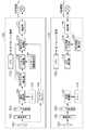
図1は、本発明の第1の実施形態に係る撮像システムの構成例を示すブロック図である。図1において、メインカメラ100は、レンズ群101、撮像素子102、A/D変換器103、画像処理部104等を有する。サブカメラ120も同様に、レンズ群121、撮像素子122、A/D変換器123、画像処理部124等を有する。また、メインカメラ100およびサブカメラ120は、通信部111、126を介して相互に通信可能である。
FIG. 1 is a block diagram showing a configuration example of an imaging system according to the first embodiment of the present invention. In FIG. 1, the
レンズ群101、121は、例えば、ズームレンズやフォーカスレンズ、絞り等の光学素子を備える。
The
撮像素子102は、レンズ群101を介して入力される被写体像を結像する。撮像素子102に結像した被写体像は、A/D変換器103にて光電変換され、画像信号として画像処理部104へ出力される。サブカメラ120においても同様に、撮像素子122に結像した被写体像がA/D変換機123より画像信号として画像処理部124へ出力される。
The
画像処理部104、124は、A/D変換器103、123で生成された画像信号(デジタル画像)を処理する。被写体像より生成された画像信号に対して所定の処理を施し、例えば、画素毎の輝度信号と色信号などの画像データを出力する。例えば、Digital Signal Processing(DSP)などから構成され、デジタル信号に対して色変換、信号処理された画像の階調変換を行うガンマ処理、ノイズ低減処理など所定の画像処理を行う。また、出力用の画像データを生成するとともに、撮像装置を制御するための各撮像パラメータを算出可能である。
The
撮像パラメータとしては、例えば絞りの制御や、ピント合わせの制御、色味を調整するホワイトバランス制御などで使われるパラメータがあげられる。ここで、メインカメラ100において、レンズ群101、撮像素子122、A/D変換器103、画像処理部104を駆動して、周囲の被写体像を取得して画像データを取得する動作を撮像動作とする。サブカメラ120においても同様に、レンズ群121、撮像素子122、A/D変換器123、画像処理部124を駆動して撮像動作を行う。
Examples of imaging parameters include parameters used in aperture control, focusing control, and white balance control for adjusting color. Here, in the
画像処理部104、124は、撮像された画像データに対して記録のための画像処理を行い、記録画像データを生成し、記録画像データは不図示の記録部に記録される。画像データを記録する動作を撮影動作とする。また、撮像された画像データに対して表示のための画像処理を行い、表示画像データを生成し、表示画像データは不図示の表示部に表示される。
The
メモリ105、125は、画像処理部104または124で使用するメモリである。
The
サブカメラ情報保持部106は、後述する通信部111、126を介して接続(連携)するサブカメラの情報を記憶する。
The sub-camera
サブカメラ検出部107は、メインカメラ100の撮像範囲内に含まれるサブカメラ120を検出する。サブカメラ120の検出方法は、例えば、撮像された画像データから被写体認識により検出してもよいし、RF(radio frequency)タグを用いて無線通信で検出してもよいが、これに限定されない。
The sub
サブカメラ判定部108は、サブカメラ情報保持部106に記憶されているサブカメラ情報とサブカメラ検出部107の検出情報からサブカメラを特定する。
The
ジャイロセンサ109は、メインカメラ100の動き(移動方向)を検知する。
The
移動方向決定部110は、サブカメラ検出部107とジャイロセンサ109から、サブカメラ120の移動方向を決定する。
The movement
通信部111、126は、外部装置または外部のネットワークと接続する。本実施形態において、通信部111は、移動方向決定部110で決定した移動情報をサブカメラ120に送信する。通信部126は、通信部111を介してメインカメラ100から送信された移動情報を受信する。
The
CPU112、130は、不図示の伝送路(バス)を介して各制御ブロックと接続されており、メインカメラ100またはサブカメラ120の装置全体を制御する。不図示のメモリ(ROM)、メモリ(RAM)を有し、ROMからロードしたプログラムに従い、メインカメラ100およびサブカメラ120の各機能ブロックの制御およびそのために必要な演算を行う。メモリ(ROM)には、CPUで実行される制御プログラムや、プログラムの実行に必要な各種の定数値が格納される。メモリ(RAM)は、プログラムの実行に必要な各種一時データを記憶するための領域である。
The
識別情報保持部127は、これを有するサブカメラ120を識別するための識別情報を保持する。
The identification
移動情報判定部128は、通信部126で受信した移動情報が、サブカメラ120自身に対する移動を指示する情報か否かを識別情報保持部127で保持する識別情報と比較して判定する。
The movement
移動制御部129は、判定部128の結果を基にサブカメラ120の移動を制御する。
The
図2は、本発明の第1の実施形態に係る撮像システムのフローを示すフローチャートである。メインカメラ100およびサブカメラ120において、CPU112、130によって各カメラの各処理ブロックを制御して実行され、CPUがメモリ(ROM)に格納されているプログラムを展開して実行することにより実現される。
FIG. 2 is a flowchart showing a flow of an imaging system according to the first embodiment of the present invention. In the
本フローチャートは、メインカメラ100とサブカメラ120が、通信部111、126を介して接続され、連携を行う状態になった場合に開始される。例えば、ユーザ操作に基づいて連携を開始する構成としてもよいし、メインカメラ100とサブカメラ120が所定の距離範囲に入った場合など、予め決められた条件で連携モードに入ってもよいが、連携を開始する条件はこれに限らない。
This flowchart is started when the
メインカメラ100とサブカメラ120が連携されると、ステップS201で、メインカメラ100は通信を介してサブカメラ120の識別情報を取得し、サブカメラ情報保持部106にサブカメラ情報として受信した識別情報を登録する。
When the
ステップS202で、メインカメラ100による撮影を開始する。ここで、撮影の開始は、例えば、撮影モードになった場合に撮影開始としてもよいし、撮影準備指示(SW1)に応じて撮影開始としてもよいし、動画撮影を開始したときに撮影開始としてもよい。なお、撮像した画像は不図示の表示手段にライブビュー画像として表示される。
In step S202, shooting by the
ステップS203で、メインカメラ100の撮像領域内のサブカメラ120の検出を行い、サブカメラ120を検出したか否かを判断する。サブカメラ120が検出された場合、ステップ204へ進み、検出されなかった場合にはステップS209へ進む。
In step S203, the
ステップS204で、メインカメラ100の動きを検出する。本実施形態においては、ジャイロセンサ109の出力に基づいてメインカメラ100の動きを検出する。
In step S204, the movement of the
ステップS205では、ステップS203で検出したサブカメラ120の位置と、ステップS204で検出したメインカメラ100の動きを基に、サブカメラ120の移動方向を決定する。詳細な移動方向の決め方は、図3を用いて後述する。
In step S205, the moving direction of the
次に、ステップS206で、移動指示情報を、通信部111を介してネットワーク等に送信し、サブカメラ120は通信部126を介して移動指示情報を受信する。
Next, in step S206, the movement instruction information is transmitted to the network or the like via the
続くステップS207で、受信した移動指示が当該サブカメラ120に対するものかを判定する。当該サブカメラ120に対する移動指示があれば、ステップS208へ進み、なければステップS209へ進む。なお、メインカメラ100とサブカメラ120が1対1で連携している場合など、当該サブカメラ120に対する移動指示情報しか受信しない構成の場合は、ステップS207の判定はなくて構わない。その場合は、ステップS207の判断をスキップして、ステップS208へ進む。
In the following step S207, it is determined whether the received movement instruction is for the
ステップS208では、受信した指示情報に基づいて移動する。 In step S208, the movement is performed based on the received instruction information.
最後にS209で、メインカメラ100の撮影が終了した場合、本フローは終了する。撮影の終了は、例えば、再生モードなどの撮影以外のモードに切り替わったとき、取得した画像が記録されたこと、動画撮影が停止されたこと、に応じて判断する。撮影が継続している場合はステップ203へ進み、撮影が終了するまで、ステップS203〜S209の処理を繰り返す。なお、メインカメラ100およびサブカメラ120は、本フローと並行して、ユーザ操作による撮影指示または所定の条件に応じて、撮像した画像を記録する撮影動作を実行することができる。
Finally, in S209, when the shooting of the
図3は、本発明の第1の実施形態に係る撮像システムの移動方向の決め方の例を示すイメージ図である。枠301および枠302は、メインカメラ100(不図示)の撮像領域を表す。撮像領域のうち、白枠で示す領域Aは記録画像の撮像領域、領域Aと外側の斜線で示す領域を含む検出領域Bは、サブカメラ120を検出する領域を表す。ドローン302はサブカメラ120で、本実施形態では撮像画角(撮像装置の位置および撮像方向)を変更可能な無人機とする。
FIG. 3 is an image diagram showing an example of how to determine the moving direction of the imaging system according to the first embodiment of the present invention. The
ここで、メインカメラ100の撮像領域を枠301から枠303に移動させたとき、ドローン302(=サブカメラ120)が検出領域303Bに入る。この時、メインカメラ100の動きと、ドローン302を検出したメインカメラ100の撮像領域の位置より、ドローン302の移動方向を決定し、ドローン302(サブカメラ120)に移動指示の情報を転送する。図3に示す例では、例えば、枠303に含まれない領域までより短い距離で移動可能であって、メインカメラ100の枠移動の方向とは異なる移動方向304を移動方向として決定する。
Here, when the imaging region of the
ドローン302(サブカメラ120)は移動指示情報を受信すると、受信した情報が当該ドローン302に対する情報であった場合、移動指示情報に基づいて移動方向304へ移動をする。なお、移動指示情報は移動方向だけでなく、移動方向と移動速度の組み合わせであってもよい。
When the drone 302 (sub-camera 120) receives the movement instruction information, if the received information is information for the
以上説明したように、本発明では、メインカメラによってサブカメラを検出した場合に、サブカメラへの移動指示を出すことで、メインカメラの撮影画像内へのサブカメラの写り込みを防ぐことが可能とする。 As described above, in the present invention, when the sub camera is detected by the main camera, it is possible to prevent the sub camera from being reflected in the captured image of the main camera by issuing a movement instruction to the sub camera. And.
本実施例では、サブカメラは撮像画角(撮像する位置および方向)などを変更可能な無人機としたが、その限りではない。同様にメインカメラも有人機、無人機の限定はない。例えば、撮像画角(撮像する位置および方向)をユーザ操作に基づいて変更する有人機である場合は、受信した移動指示を表示手段に表示することで、移動指示を通知する構成としてもよい。 In this embodiment, the sub camera is an unmanned aerial vehicle whose imaging angle of view (position and direction of imaging) can be changed, but this is not the case. Similarly, the main camera is not limited to manned and unmanned vehicles. For example, in the case of a manned vehicle that changes the imaging angle of view (position and direction of imaging) based on a user operation, the movement instruction may be notified by displaying the received movement instruction on the display means.
また本実施例では、メインカメラの撮像部を一つのみで構成しているが、記録画像用の撮像部と検出用の撮像部を別にする構成でも良い。また本実施例ではメインカメラが移動方向を決定しているが、メインカメラからの情報を基にサブカメラ側で移動方向を決定する構成でも良い。また本実施例ではメインカメラの動きをジャイロセンサで検出していたが、撮像画像の情報から判断するなど、その限りではない。また本実施例では検出領域を記録画像領域より広い構成としていたが、その限りではない。 Further, in this embodiment, the image pickup unit of the main camera is configured by only one, but the image pickup section for recorded images and the image pickup section for detection may be separated. Further, in this embodiment, the main camera determines the moving direction, but the sub camera may determine the moving direction based on the information from the main camera. Further, in this embodiment, the movement of the main camera is detected by the gyro sensor, but this is not the case, such as judging from the information of the captured image. Further, in this embodiment, the detection area is wider than the recorded image area, but this is not the case.
(第2の実施形態)
本発明の第2の実施形態を説明する。本実施形態の撮影システムに関する詳細を図4、図5に示す。本実施形態では、サブカメラの動作モードに応じて、メインカメラからの移動指示に対する判定が異なる点で第1の実施形態と異なる。なお、第1の実施形態と実質的に同一の機能を有する構成については同一の符号を付し、その説明を省略する。
(Second Embodiment)
A second embodiment of the present invention will be described. Details of the imaging system of this embodiment are shown in FIGS. 4 and 5. This embodiment is different from the first embodiment in that the determination for the movement instruction from the main camera is different depending on the operation mode of the sub camera. The configurations having substantially the same functions as those of the first embodiment are designated by the same reference numerals, and the description thereof will be omitted.
図4は、本発明の第2の実施形態に係る撮像システムの構成例を示すブロック図である。 FIG. 4 is a block diagram showing a configuration example of an imaging system according to a second embodiment of the present invention.
本実施形態において、サブカメラ120は、管理部401、移動制御部402、通信部403を有する。メインカメラ100は、通信部404、表示部405を有する。
In the present embodiment, the
管理部401は、サブカメラ120が現在どの動作モードで動作しているかを管理する。
The
移動制御部402は、判定部128の識別結果および管理部401から取得した現在の動作モードに関する情報を基にサブカメラ120の移動を制御する。
The
通信部403は、サブカメラ120の通信部で、メインカメラ100の後述する通信部404から情報を受信し、また、メインカメラ100へ動作モードの情報を送信する。
The
通信部404は、メインカメラ100の通信部で、サブカメラ120へ移動方向決定部110で決定した移動指示情報の送信し、また、サブカメラからの動作モードの情報を受信する。
The
表示部405は、メインカメラ100が有する表示部で、撮像領域のLV画像(ライブビュー画像)や、撮影後のレックレビューの表示、および、不図示の記憶媒体に記録された画像の再生表示などを行う。本実施形態においては、表示部405は、サブカメラ120の動作モードを表示することができる。また、メニュー画面や設定画面を表示し、その表示に対してユーザが操作することに応答して、メインカメラ100又はネットワークを介してサブカメラ120など、他の装置への指示が可能な構成とすることもできる。
The
図5は、本発明の第2の実施形態に係る撮影システムのフローを示すフローチャートである。メインカメラ100およびサブカメラ120において、CPU112、130によって各カメラの各処理ブロックを制御して実行され、CPUがメモリ(ROM)に格納されているプログラムを展開して実行することにより実現される。図5において、ステップS201〜S209の処理は図2の処理と同様のため、説明は省略する。
FIG. 5 is a flowchart showing a flow of a photographing system according to a second embodiment of the present invention. In the
ステップS207で、当該サブカメラ120に移動指示があった場合は、ステップS501へ進む。
If the
ステップS501で、移動指示があったサブカメラ120の動作モードが、記録のための本画像を撮影する本画像撮影モードであるか否かを判断する。本画像撮影中である場合はステップS502へ進み、本画像撮影中でない場合にはステップS208へ進む。
In step S501, it is determined whether or not the operation mode of the
ステップS502へ進んだ場合、メインカメラ100からの移動指示には従わず、メインカメラ100に移動不可の情報を送信する。
When the process proceeds to step S502, the non-movable information is transmitted to the
続くステップS503で、メインカメラ100は受信した移動不可の情報を表示部に表示する。
In the following step S503, the
その後、ステップS209へ進み、撮影が終了した場合に本フローが終了する。撮影終了までは、ループ処理により本フローを繰り返すため、サブカメラ120が本画像撮影モードでなくなった場合には、移動指示に応じて移動を実行することになる。
After that, the process proceeds to step S209, and when the shooting is completed, this flow ends. Since this flow is repeated by loop processing until the end of shooting, when the
本実施例では、メインカメラの撮像部を一つのみで構成しているが、記録画像用の撮像部と検出用の撮像部を別にする構成でも良い。また本実施例ではメインカメラが移動方向を決定しているが、メインカメラからの情報を基にサブカメラ側で移動方向を決定する構成でも良い。また本実施例ではメインカメラの動きを検出するためにジャイロセンサを用いていたが、撮像画像の情報から判断するなど、その限りではない。 In this embodiment, the image pickup unit of the main camera is configured by only one, but the image pickup section for recorded images and the image pickup section for detection may be separated. Further, in this embodiment, the main camera determines the moving direction, but the sub camera may determine the moving direction based on the information from the main camera. Further, in this embodiment, a gyro sensor is used to detect the movement of the main camera, but this is not the case, such as judging from the information of the captured image.
また本実施例ではサブカメラの動作モードとして、サブカメラが本画像撮影中の場合に移動指示に従わない構成としたが、例えば、評価値取得モードなど、他の要因により移動中である場合にも、受信した移動指示に従わない構成としてもよい。また、移動指示を無視した場合にも、本画像撮影モードなどの所定のモードから抜けた場合には、受信していた移動指示に基づいて移動する構成としてもよい。 Further, in this embodiment, the operation mode of the sub camera is configured so that the sub camera does not follow the movement instruction when the sub camera is taking the main image. However, when the sub camera is moving due to other factors such as the evaluation value acquisition mode. However, the configuration may not follow the received movement instruction. Further, even when the movement instruction is ignored, when the predetermined mode such as the main image shooting mode is exited, the movement may be configured based on the received movement instruction.
(第3の実施形態)
本発明の第3の実施形態を説明する。本実施形態の撮影システムに関する詳細を図6、図7に示す。本実施例では、メインカメラ100が、サブカメラ120の検出状態に応じて、撮影の動作を切り替える点で第1および第2の実施形態と異なる。なお、第1、第2の実施形態と実質的に同一の機能を有する構成については同一の符号を付し、その説明を省略する。
(Third Embodiment)
A third embodiment of the present invention will be described. Details of the imaging system of this embodiment are shown in FIGS. 6 and 7. The present embodiment differs from the first and second embodiments in that the
図6は、本発明の第3の実施形態に係る撮影システムの構成例を示すブロック図である。本実施形態のメインカメラ100は、さらに撮像制御部601を有する。
FIG. 6 is a block diagram showing a configuration example of a photographing system according to a third embodiment of the present invention. The
撮像制御部601は、サブカメラ検出部107によるサブカメラ120の検出結果に応じて、メインカメラ100の撮像動作を制御する。
The image
図7は、本発明の第3の実施形態に係る撮影システムのフローを示すフローチャートである。メインカメラ100およびサブカメラ120において、CPU112、130によって各カメラの各処理ブロックを制御して実行され、CPUがメモリ(ROM)に格納されているプログラムを展開して実行することにより実現される。図7において、ステップS201〜S209は図2と同様のため、詳細な説明は省略する。
FIG. 7 is a flowchart showing a flow of a photographing system according to a third embodiment of the present invention. In the
ステップS203で、メインカメラ100の撮像領域内にサブカメラ120を検出した場合にはステップS701へ進み、検出しなかった場合にはステップS702へ進む。
If the
ステップS701で、メインカメラ100は本画像撮影不可モードが設定される。本画像撮影不可モードには、例えば、メインカメラ100の不図示のシャッターボタンなどを押下して撮影指示をしても、撮像画像の記録ができない動作である。その後、ステップS204へ進み、その後のフローは前述の第1、第2の実施形態と同様であるため、詳細な説明は省略する。
In step S701, the
一方、ステップS702へ進んだ場合は、メインカメラ100が本画像撮影不可モードであるか否かを判断する。本画像撮影不可モードである場合にはステップS703へ進み、本画像撮影不可モードでない場合はステップS209へ進む。
On the other hand, when the process proceeds to step S702, it is determined whether or not the
ステップS203でサブカメラが検出されず、ステップS702で本画像撮影不可モード中であった場合、ステップS703へ進み、本画像撮影不可モードを解除する。その後、ステップS209へ進み、撮影が終了した場合に本フローが終了する。 If the sub camera is not detected in step S203 and the main image capture impossible mode is in step S702, the process proceeds to step S703 to cancel the main image capture impossible mode. After that, the process proceeds to step S209, and when the shooting is completed, this flow ends.
以上が本発明の好ましい実施形態の説明であるが、本発明は、本発明の技術思想の範囲内において、上記実施形態に限定されるものではなく、対象となる回路形態により適時変更されて適応するべきものである。本発明をその好適な実施形態としてデジタルカメラとドローンカメラから成るシステムに基づいて詳述してきたが、本発明はこれら特定の実施形態に限られるものではなく、この発明の要旨を逸脱しない範囲の様々な形態も本発明に含まれる。 The above is a description of a preferred embodiment of the present invention, but the present invention is not limited to the above embodiment within the scope of the technical idea of the present invention, and is appropriately modified and adapted depending on the target circuit form. It should be done. Although the present invention has been described in detail as a preferred embodiment thereof based on a system including a digital camera and a drone camera, the present invention is not limited to these specific embodiments and does not deviate from the gist of the present invention. Various forms are also included in the present invention.
また、本発明は、例えばシステム、装置、方法、コンピュータプログラムもしくは記録媒体などとしての実施形態も可能であり、具体的には、1つの装置で実現しても、複数の装置からなるシステムに適用してもよい。本実施形態に係る撮像装置を構成する各手段および撮像装置の制御方法の各ステップは、コンピュータのメモリなどに記憶されたプログラムが動作することによっても実現できる。このコンピュータプログラムおよびこのプログラムを記録したコンピュータ読み取り可能な記録媒体は本発明に含まれる。 Further, the present invention can be implemented as, for example, a system, a device, a method, a computer program, a recording medium, or the like. Specifically, even if it is realized by one device, it is applied to a system composed of a plurality of devices. You may. Each means constituting the image pickup apparatus and each step of the control method of the image pickup apparatus according to the present embodiment can also be realized by operating a program stored in a memory of a computer or the like. The computer program and a computer-readable recording medium on which the program is recorded are included in the present invention.
本発明は、上述の実施形態の1以上の機能を実現するプログラムを、ネットワーク又は記憶媒体を介してシステム又は装置に供給し、そのシステム又は装置のコンピュータにおける1つ以上のプロセッサーがプログラムを読出し実行する処理でも実現可能である。また、1以上の機能を実現する回路(例えば、ASIC)によっても実現可能である。 The present invention supplies a program that realizes one or more functions of the above-described embodiment to a system or device via a network or storage medium, and one or more processors in the computer of the system or device reads and executes the program. It can also be realized by the processing to be performed. It can also be realized by a circuit (for example, ASIC) that realizes one or more functions.
100 メインカメラ
107 サブカメラ検出部
108 サブカメラ判定部
110 移動方向決定部
111 通信部
120 サブカメラ
126 通信部
128 移動情報判定部
129 移動制御部
100
Claims (18)
第2の撮像装置と、
前記第1および第2の撮像装置の間で通信する通信手段と、
前記第1の撮像装置の撮像領域内に前記第2の撮像装置が含まれる場合に、該第2の撮像装置へ該撮像領域の外への移動を指示する指示手段と、
を有することを特徴とする撮影システム。 The first imaging device and
The second imaging device and
A communication means for communicating between the first and second image pickup devices, and
When the second imaging device is included in the imaging region of the first imaging device, an instruction means for instructing the second imaging device to move out of the imaging region, and
A photography system characterized by having.
前記検出手段により前記第2の撮像装置が検出された場合に、前記第2の撮像装置の移動を指示することを特徴とする請求項1に記載の撮影システム。 The instruction means includes a detection means for detecting the second image pickup device included in the image pickup region of the first image pickup device.
The imaging system according to claim 1, wherein when the second imaging device is detected by the detection means, the movement of the second imaging device is instructed.
前記指示手段による指示に基づいて前記第2の撮像装置を移動させる制御手段と、
を有することを特徴とする請求項1乃至3のいずれか1項に記載の撮影システム。 The second imaging device is an unmanned aerial vehicle whose position can be moved.
A control means for moving the second image pickup apparatus based on an instruction by the instruction means, and a control means for moving the second image pickup apparatus.
The photographing system according to any one of claims 1 to 3, wherein the photographing system has.
を有することを特徴とする請求項2乃至8のいずれか1項に記載の撮影システム。 When the second image pickup device is detected in the image pickup region of the first image pickup device by the detection means, the first image pickup device is controlled so as not to capture the main image for recording. Shooting control means and
The photographing system according to any one of claims 2 to 8, wherein the photographing system has.
他の撮像装置と通信する通信手段と、
前記撮像手段が撮像する撮像領域内の前記他の撮像装置を検出する検出手段と、
前記検出手段により前記撮像領域内に前記他の撮像装置が検出された場合に、該他の撮像装置に対する移動を指示する指示手段と、
を有することを特徴とする撮像装置。 An imaging means that captures the subject,
With communication means to communicate with other imaging devices,
A detection means for detecting the other image pickup device in the image pickup region to be imaged by the image pickup means, and a detection means.
When the other imaging device is detected in the imaging region by the detecting means, the instruction means for instructing the movement to the other imaging device and the instruction means.
An imaging device characterized by having.
前記撮像領域は、前記記録手段で記録する前記画像の領域より広い範囲であることを特徴とする請求項10に記載の撮像装置。 It has a recording means for recording an captured image, and has
The imaging device according to claim 10, wherein the imaging region is a wider range than the region of the image recorded by the recording means.
前記指示手段は、さらに前記動き検出手段により検出された動きに基づいて、前記他の撮像装置の移動方向を決定することを特徴とする請求項12に記載の撮像装置。 It has a motion detecting means for detecting its own motion,
The imaging device according to claim 12, wherein the instruction means further determines a moving direction of the other imaging device based on the motion detected by the motion detecting means.
前記第1の撮像装置の撮像領域内に前記第2の撮像装置が含まれる場合に、該第2の撮像装置を該撮像領域の外へ移動させる移動ステップと、
を有することを特徴とする制御方法。 It is a control method of an imaging system including a first imaging apparatus and a second imaging apparatus capable of communicating with the first imaging apparatus.
When the second imaging device is included in the imaging region of the first imaging device, a moving step of moving the second imaging device out of the imaging region, and
A control method characterized by having.
前記検出ステップにより前記第2の撮像装置が検出された場合に前記移動ステップを実行することを特徴とする請求項15に記載の制御方法。 It has a detection step of detecting the second image pickup device included in the image pickup region of the first image pickup device.
The control method according to claim 15, wherein the moving step is executed when the second imaging device is detected by the detection step.
Priority Applications (2)
| Application Number | Priority Date | Filing Date | Title |
|---|---|---|---|
| JP2020028054A JP2021132352A (en) | 2020-02-21 | 2020-02-21 | Imaging device, photographing system, and control method thereof |
| US17/178,120 US11290631B2 (en) | 2020-02-21 | 2021-02-17 | Image capture apparatus, image capture system, and control method |
Applications Claiming Priority (1)
| Application Number | Priority Date | Filing Date | Title |
|---|---|---|---|
| JP2020028054A JP2021132352A (en) | 2020-02-21 | 2020-02-21 | Imaging device, photographing system, and control method thereof |
Publications (2)
| Publication Number | Publication Date |
|---|---|
| JP2021132352A true JP2021132352A (en) | 2021-09-09 |
| JP2021132352A5 JP2021132352A5 (en) | 2023-02-24 |
Family
ID=77365389
Family Applications (1)
| Application Number | Title | Priority Date | Filing Date |
|---|---|---|---|
| JP2020028054A Pending JP2021132352A (en) | 2020-02-21 | 2020-02-21 | Imaging device, photographing system, and control method thereof |
Country Status (2)
| Country | Link |
|---|---|
| US (1) | US11290631B2 (en) |
| JP (1) | JP2021132352A (en) |
Families Citing this family (2)
| Publication number | Priority date | Publication date | Assignee | Title |
|---|---|---|---|---|
| WO2019140699A1 (en) * | 2018-01-22 | 2019-07-25 | SZ DJI Technology Co., Ltd. | Methods and system for multi-target tracking |
| US20230188855A1 (en) * | 2020-05-21 | 2023-06-15 | Nec Corporation | Installation assistance apparatus, installation assistance method, and non-transitory computer-readable storage medium |
Family Cites Families (5)
| Publication number | Priority date | Publication date | Assignee | Title |
|---|---|---|---|---|
| JP2001025003A (en) | 1999-07-08 | 2001-01-26 | Canon Inc | Camera system and camera control method |
| JP3852745B2 (en) * | 2000-02-28 | 2006-12-06 | 株式会社日立国際電気 | Object detection method and object detection apparatus |
| JP3643513B2 (en) * | 2000-03-01 | 2005-04-27 | 株式会社日立国際電気 | Intruding object monitoring method and intruding object monitoring apparatus |
| CN106791586A (en) * | 2015-11-19 | 2017-05-31 | 杭州海康威视数字技术股份有限公司 | A kind of method and monitoring device, device, system being monitored to mobile target |
| US10277831B2 (en) * | 2016-03-25 | 2019-04-30 | Fuji Xerox Co., Ltd. | Position identifying apparatus and method, path identifying apparatus, and non-transitory computer readable medium |
-
2020
- 2020-02-21 JP JP2020028054A patent/JP2021132352A/en active Pending
-
2021
- 2021-02-17 US US17/178,120 patent/US11290631B2/en active Active
Also Published As
| Publication number | Publication date |
|---|---|
| US20210266451A1 (en) | 2021-08-26 |
| US11290631B2 (en) | 2022-03-29 |
Similar Documents
| Publication | Publication Date | Title |
|---|---|---|
| JP4761146B2 (en) | Imaging apparatus and program thereof | |
| JP4976160B2 (en) | Imaging device | |
| EP1874043B1 (en) | Image pick up apparatus | |
| JP5019939B2 (en) | Imaging apparatus and imaging method | |
| JP5661373B2 (en) | Imaging system, imaging apparatus, and control method thereof | |
| JP2015198439A (en) | Image processing device, control method thereof, imaging apparatus and program | |
| JP2008299784A (en) | Object determination device and program therefor | |
| JP5843525B2 (en) | Imaging apparatus and control method thereof | |
| JP2021132352A (en) | Imaging device, photographing system, and control method thereof | |
| JP2007081991A (en) | Imaging device and control method thereof | |
| JP4807582B2 (en) | Image processing apparatus, imaging apparatus, and program thereof | |
| JP5014267B2 (en) | Imaging device | |
| JP6758950B2 (en) | Imaging device, its control method and program | |
| JP2006245792A (en) | Photographing apparatus and program | |
| JP2007116372A (en) | Digital camera | |
| JP2014011782A (en) | Imaging apparatus, and imaging method and program therefor | |
| JP4888829B2 (en) | Movie processing device, movie shooting device, and movie shooting program | |
| JP5962974B2 (en) | Imaging apparatus, imaging method, and program | |
| JP2020205560A (en) | Imaging apparatus and control method of the same | |
| JP2002305676A (en) | Electronic camera | |
| JP2004117195A (en) | Digital camera with speed measuring function | |
| JP6493746B2 (en) | Image tracking device and image tracking method | |
| CN113014796B (en) | Image processing apparatus, image capturing apparatus, image processing method, and storage medium | |
| US20160057350A1 (en) | Imaging apparatus, image processing method, and non-transitory computer-readable medium | |
| JP2018113624A (en) | Imaging apparatus and control method for imaging apparatus |
Legal Events
| Date | Code | Title | Description |
|---|---|---|---|
| RD01 | Notification of change of attorney |
Free format text: JAPANESE INTERMEDIATE CODE: A7421 Effective date: 20200324 |
|
| A521 | Request for written amendment filed |
Free format text: JAPANESE INTERMEDIATE CODE: A523 Effective date: 20230215 |
|
| A621 | Written request for application examination |
Free format text: JAPANESE INTERMEDIATE CODE: A621 Effective date: 20230215 |
|
| RD01 | Notification of change of attorney |
Free format text: JAPANESE INTERMEDIATE CODE: A7421 Effective date: 20231213 |
|
| A977 | Report on retrieval |
Free format text: JAPANESE INTERMEDIATE CODE: A971007 Effective date: 20240126 |
|
| A131 | Notification of reasons for refusal |
Free format text: JAPANESE INTERMEDIATE CODE: A131 Effective date: 20240130 |