JP2018527997A - Apparatus, method and system for obtaining medical diagnostic information, and provision of telemedicine services - Google Patents
Apparatus, method and system for obtaining medical diagnostic information, and provision of telemedicine services Download PDFInfo
- Publication number
- JP2018527997A JP2018527997A JP2018511350A JP2018511350A JP2018527997A JP 2018527997 A JP2018527997 A JP 2018527997A JP 2018511350 A JP2018511350 A JP 2018511350A JP 2018511350 A JP2018511350 A JP 2018511350A JP 2018527997 A JP2018527997 A JP 2018527997A
- Authority
- JP
- Japan
- Prior art keywords
- subject
- diagnostic
- information
- medical
- ear
- Prior art date
- Legal status (The legal status is an assumption and is not a legal conclusion. Google has not performed a legal analysis and makes no representation as to the accuracy of the status listed.)
- Pending
Links
- NRHDCQLCSOWVTF-UHFFFAOYSA-N C1CCCNCCCC1 Chemical compound C1CCCNCCCC1 NRHDCQLCSOWVTF-UHFFFAOYSA-N 0.000 description 1
Images


Classifications
-
- G—PHYSICS
- G16—INFORMATION AND COMMUNICATION TECHNOLOGY [ICT] SPECIALLY ADAPTED FOR SPECIFIC APPLICATION FIELDS
- G16H—HEALTHCARE INFORMATICS, i.e. INFORMATION AND COMMUNICATION TECHNOLOGY [ICT] SPECIALLY ADAPTED FOR THE HANDLING OR PROCESSING OF MEDICAL OR HEALTHCARE DATA
- G16H10/00—ICT specially adapted for the handling or processing of patient-related medical or healthcare data
- G16H10/60—ICT specially adapted for the handling or processing of patient-related medical or healthcare data for patient-specific data, e.g. for electronic patient records
-
- A—HUMAN NECESSITIES
- A61—MEDICAL OR VETERINARY SCIENCE; HYGIENE
- A61B—DIAGNOSIS; SURGERY; IDENTIFICATION
- A61B1/00—Instruments for performing medical examinations of the interior of cavities or tubes of the body by visual or photographical inspection, e.g. endoscopes; Illuminating arrangements therefor
- A61B1/00002—Operational features of endoscopes
- A61B1/00011—Operational features of endoscopes characterised by signal transmission
- A61B1/00016—Operational features of endoscopes characterised by signal transmission using wireless means
-
- A—HUMAN NECESSITIES
- A61—MEDICAL OR VETERINARY SCIENCE; HYGIENE
- A61B—DIAGNOSIS; SURGERY; IDENTIFICATION
- A61B1/00—Instruments for performing medical examinations of the interior of cavities or tubes of the body by visual or photographical inspection, e.g. endoscopes; Illuminating arrangements therefor
- A61B1/04—Instruments for performing medical examinations of the interior of cavities or tubes of the body by visual or photographical inspection, e.g. endoscopes; Illuminating arrangements therefor combined with photographic or television appliances
-
- A—HUMAN NECESSITIES
- A61—MEDICAL OR VETERINARY SCIENCE; HYGIENE
- A61B—DIAGNOSIS; SURGERY; IDENTIFICATION
- A61B1/00—Instruments for performing medical examinations of the interior of cavities or tubes of the body by visual or photographical inspection, e.g. endoscopes; Illuminating arrangements therefor
- A61B1/06—Instruments for performing medical examinations of the interior of cavities or tubes of the body by visual or photographical inspection, e.g. endoscopes; Illuminating arrangements therefor with illuminating arrangements
- A61B1/0661—Endoscope light sources
- A61B1/0669—Endoscope light sources at proximal end of an endoscope
-
- A—HUMAN NECESSITIES
- A61—MEDICAL OR VETERINARY SCIENCE; HYGIENE
- A61B—DIAGNOSIS; SURGERY; IDENTIFICATION
- A61B1/00—Instruments for performing medical examinations of the interior of cavities or tubes of the body by visual or photographical inspection, e.g. endoscopes; Illuminating arrangements therefor
- A61B1/06—Instruments for performing medical examinations of the interior of cavities or tubes of the body by visual or photographical inspection, e.g. endoscopes; Illuminating arrangements therefor with illuminating arrangements
- A61B1/07—Instruments for performing medical examinations of the interior of cavities or tubes of the body by visual or photographical inspection, e.g. endoscopes; Illuminating arrangements therefor with illuminating arrangements using light-conductive means, e.g. optical fibres
-
- A—HUMAN NECESSITIES
- A61—MEDICAL OR VETERINARY SCIENCE; HYGIENE
- A61B—DIAGNOSIS; SURGERY; IDENTIFICATION
- A61B1/00—Instruments for performing medical examinations of the interior of cavities or tubes of the body by visual or photographical inspection, e.g. endoscopes; Illuminating arrangements therefor
- A61B1/227—Instruments for performing medical examinations of the interior of cavities or tubes of the body by visual or photographical inspection, e.g. endoscopes; Illuminating arrangements therefor for ears, i.e. otoscopes
-
- A—HUMAN NECESSITIES
- A61—MEDICAL OR VETERINARY SCIENCE; HYGIENE
- A61B—DIAGNOSIS; SURGERY; IDENTIFICATION
- A61B1/00—Instruments for performing medical examinations of the interior of cavities or tubes of the body by visual or photographical inspection, e.g. endoscopes; Illuminating arrangements therefor
- A61B1/233—Instruments for performing medical examinations of the interior of cavities or tubes of the body by visual or photographical inspection, e.g. endoscopes; Illuminating arrangements therefor for the nose, i.e. nasoscopes, e.g. testing of patency of Eustachian tubes
-
- A—HUMAN NECESSITIES
- A61—MEDICAL OR VETERINARY SCIENCE; HYGIENE
- A61B—DIAGNOSIS; SURGERY; IDENTIFICATION
- A61B1/00—Instruments for performing medical examinations of the interior of cavities or tubes of the body by visual or photographical inspection, e.g. endoscopes; Illuminating arrangements therefor
- A61B1/24—Instruments for performing medical examinations of the interior of cavities or tubes of the body by visual or photographical inspection, e.g. endoscopes; Illuminating arrangements therefor for the mouth, i.e. stomatoscopes, e.g. with tongue depressors; Instruments for opening or keeping open the mouth
-
- A—HUMAN NECESSITIES
- A61—MEDICAL OR VETERINARY SCIENCE; HYGIENE
- A61B—DIAGNOSIS; SURGERY; IDENTIFICATION
- A61B1/00—Instruments for performing medical examinations of the interior of cavities or tubes of the body by visual or photographical inspection, e.g. endoscopes; Illuminating arrangements therefor
- A61B1/273—Instruments for performing medical examinations of the interior of cavities or tubes of the body by visual or photographical inspection, e.g. endoscopes; Illuminating arrangements therefor for the upper alimentary canal, e.g. oesophagoscopes, gastroscopes
-
- A—HUMAN NECESSITIES
- A61—MEDICAL OR VETERINARY SCIENCE; HYGIENE
- A61B—DIAGNOSIS; SURGERY; IDENTIFICATION
- A61B5/00—Measuring for diagnostic purposes; Identification of persons
- A61B5/0002—Remote monitoring of patients using telemetry, e.g. transmission of vital signals via a communication network
- A61B5/0015—Remote monitoring of patients using telemetry, e.g. transmission of vital signals via a communication network characterised by features of the telemetry system
- A61B5/0022—Monitoring a patient using a global network, e.g. telephone networks, internet
-
- A—HUMAN NECESSITIES
- A61—MEDICAL OR VETERINARY SCIENCE; HYGIENE
- A61B—DIAGNOSIS; SURGERY; IDENTIFICATION
- A61B5/00—Measuring for diagnostic purposes; Identification of persons
- A61B5/05—Detecting, measuring or recording for diagnosis by means of electric currents or magnetic fields; Measuring using microwaves or radio waves
-
- A—HUMAN NECESSITIES
- A61—MEDICAL OR VETERINARY SCIENCE; HYGIENE
- A61B—DIAGNOSIS; SURGERY; IDENTIFICATION
- A61B5/00—Measuring for diagnostic purposes; Identification of persons
- A61B5/68—Arrangements of detecting, measuring or recording means, e.g. sensors, in relation to patient
- A61B5/6801—Arrangements of detecting, measuring or recording means, e.g. sensors, in relation to patient specially adapted to be attached to or worn on the body surface
- A61B5/6813—Specially adapted to be attached to a specific body part
- A61B5/6814—Head
- A61B5/6815—Ear
- A61B5/6817—Ear canal
-
- A—HUMAN NECESSITIES
- A61—MEDICAL OR VETERINARY SCIENCE; HYGIENE
- A61B—DIAGNOSIS; SURGERY; IDENTIFICATION
- A61B5/00—Measuring for diagnostic purposes; Identification of persons
- A61B5/68—Arrangements of detecting, measuring or recording means, e.g. sensors, in relation to patient
- A61B5/6801—Arrangements of detecting, measuring or recording means, e.g. sensors, in relation to patient specially adapted to be attached to or worn on the body surface
- A61B5/6813—Specially adapted to be attached to a specific body part
- A61B5/6814—Head
- A61B5/682—Mouth, e.g., oral cavity; tongue; Lips; Teeth
-
- A—HUMAN NECESSITIES
- A61—MEDICAL OR VETERINARY SCIENCE; HYGIENE
- A61B—DIAGNOSIS; SURGERY; IDENTIFICATION
- A61B5/00—Measuring for diagnostic purposes; Identification of persons
- A61B5/68—Arrangements of detecting, measuring or recording means, e.g. sensors, in relation to patient
- A61B5/6801—Arrangements of detecting, measuring or recording means, e.g. sensors, in relation to patient specially adapted to be attached to or worn on the body surface
- A61B5/684—Indicating the position of the sensor on the body
-
- A—HUMAN NECESSITIES
- A61—MEDICAL OR VETERINARY SCIENCE; HYGIENE
- A61B—DIAGNOSIS; SURGERY; IDENTIFICATION
- A61B7/00—Instruments for auscultation
- A61B7/003—Detecting lung or respiration noise
-
- A—HUMAN NECESSITIES
- A61—MEDICAL OR VETERINARY SCIENCE; HYGIENE
- A61B—DIAGNOSIS; SURGERY; IDENTIFICATION
- A61B7/00—Instruments for auscultation
- A61B7/02—Stethoscopes
- A61B7/04—Electric stethoscopes
-
- A—HUMAN NECESSITIES
- A61—MEDICAL OR VETERINARY SCIENCE; HYGIENE
- A61B—DIAGNOSIS; SURGERY; IDENTIFICATION
- A61B90/00—Instruments, implements or accessories specially adapted for surgery or diagnosis and not covered by any of the groups A61B1/00 - A61B50/00, e.g. for luxation treatment or for protecting wound edges
- A61B90/36—Image-producing devices or illumination devices not otherwise provided for
- A61B90/361—Image-producing devices, e.g. surgical cameras
-
- G—PHYSICS
- G16—INFORMATION AND COMMUNICATION TECHNOLOGY [ICT] SPECIALLY ADAPTED FOR SPECIFIC APPLICATION FIELDS
- G16H—HEALTHCARE INFORMATICS, i.e. INFORMATION AND COMMUNICATION TECHNOLOGY [ICT] SPECIALLY ADAPTED FOR THE HANDLING OR PROCESSING OF MEDICAL OR HEALTHCARE DATA
- G16H30/00—ICT specially adapted for the handling or processing of medical images
- G16H30/20—ICT specially adapted for the handling or processing of medical images for handling medical images, e.g. DICOM, HL7 or PACS
-
- G—PHYSICS
- G16—INFORMATION AND COMMUNICATION TECHNOLOGY [ICT] SPECIALLY ADAPTED FOR SPECIFIC APPLICATION FIELDS
- G16H—HEALTHCARE INFORMATICS, i.e. INFORMATION AND COMMUNICATION TECHNOLOGY [ICT] SPECIALLY ADAPTED FOR THE HANDLING OR PROCESSING OF MEDICAL OR HEALTHCARE DATA
- G16H40/00—ICT specially adapted for the management or administration of healthcare resources or facilities; ICT specially adapted for the management or operation of medical equipment or devices
- G16H40/60—ICT specially adapted for the management or administration of healthcare resources or facilities; ICT specially adapted for the management or operation of medical equipment or devices for the operation of medical equipment or devices
- G16H40/67—ICT specially adapted for the management or administration of healthcare resources or facilities; ICT specially adapted for the management or operation of medical equipment or devices for the operation of medical equipment or devices for remote operation
-
- G—PHYSICS
- G16—INFORMATION AND COMMUNICATION TECHNOLOGY [ICT] SPECIALLY ADAPTED FOR SPECIFIC APPLICATION FIELDS
- G16H—HEALTHCARE INFORMATICS, i.e. INFORMATION AND COMMUNICATION TECHNOLOGY [ICT] SPECIALLY ADAPTED FOR THE HANDLING OR PROCESSING OF MEDICAL OR HEALTHCARE DATA
- G16H50/00—ICT specially adapted for medical diagnosis, medical simulation or medical data mining; ICT specially adapted for detecting, monitoring or modelling epidemics or pandemics
- G16H50/20—ICT specially adapted for medical diagnosis, medical simulation or medical data mining; ICT specially adapted for detecting, monitoring or modelling epidemics or pandemics for computer-aided diagnosis, e.g. based on medical expert systems
-
- G—PHYSICS
- G16—INFORMATION AND COMMUNICATION TECHNOLOGY [ICT] SPECIALLY ADAPTED FOR SPECIFIC APPLICATION FIELDS
- G16H—HEALTHCARE INFORMATICS, i.e. INFORMATION AND COMMUNICATION TECHNOLOGY [ICT] SPECIALLY ADAPTED FOR THE HANDLING OR PROCESSING OF MEDICAL OR HEALTHCARE DATA
- G16H80/00—ICT specially adapted for facilitating communication between medical practitioners or patients, e.g. for collaborative diagnosis, therapy or health monitoring
-
- A—HUMAN NECESSITIES
- A61—MEDICAL OR VETERINARY SCIENCE; HYGIENE
- A61B—DIAGNOSIS; SURGERY; IDENTIFICATION
- A61B90/00—Instruments, implements or accessories specially adapted for surgery or diagnosis and not covered by any of the groups A61B1/00 - A61B50/00, e.g. for luxation treatment or for protecting wound edges
- A61B90/03—Automatic limiting or abutting means, e.g. for safety
- A61B2090/033—Abutting means, stops, e.g. abutting on tissue or skin
- A61B2090/036—Abutting means, stops, e.g. abutting on tissue or skin abutting on tissue or skin
Abstract
【解決手段】 本発明は、ユーザのための、医療情報を含む診断情報を取得し、情報を遠隔地に送信し、情報を評価し、結果的な診断および治療情報を次の行動のためにユーザおよび/または第三者に送信するための、様々なシステム、ツール、および方法に関する。本発明は、健康管理サービスおよび/または診断が遠くから遠隔的に提供されることを可能にする、消費者およびユーザにとって使いやすい遠隔治療システムおよび手順を提供する。 The present invention acquires diagnostic information including medical information for a user, transmits the information to a remote location, evaluates the information, and provides the resulting diagnostic and treatment information for the next action. It relates to various systems, tools and methods for transmission to users and / or third parties. The present invention provides consumer and user-friendly teletherapy systems and procedures that allow health care services and / or diagnostics to be provided remotely from a distance.
Description
本明細書は、その全内容が本明細書に組み込まれる、2015年5月12日付けで出願された米国特許仮出願第62/160,468号明細書の優先権の利益を主張する。本明細書はまた、参照によりその全内容が本明細書に組み込まれる、2013年6月27日付けで出願された米国特許出願第13/929,591号明細書および2012年6月27日付けで出願された米国特許仮出願第61/664,920号明細書の優先権の利益を主張する。 This specification claims the benefit of priority of US Provisional Application No. 62 / 160,468, filed May 12, 2015, the entire contents of which are incorporated herein. This specification also includes US Patent Application No. 13 / 929,591, filed June 27, 2013 and June 27, 2012, the entire contents of which are incorporated herein by reference. Claims the benefit of the priority of US Provisional Application No. 61 / 664,920, filed in U.S. Pat.
本発明は、ユーザに関する、医療情報を含む診断情報を取得し、情報を遠隔地に送信し、情報を評価し、結果的な診断および治療情報を次の行動のためにユーザおよび/または第三者に送信するための、様々なシステム、ツール、および方法に関する。より具体的には、本発明は、健康管理サービスおよび/または診断が遠くから遠隔的に提供されることを可能にする、消費者およびユーザにとって使いやすい遠隔治療システムおよび手順に関する。 The present invention obtains diagnostic information about a user, including medical information, transmits the information to a remote location, evaluates the information, and sends the resulting diagnostic and treatment information to the user and / or third party for subsequent actions. Relates to various systems, tools, and methods for transmission to a consumer. More specifically, the present invention relates to consumer and user-friendly teletherapy systems and procedures that allow health care services and / or diagnostics to be provided remotely from a distance.
現在、傷害または未診断の疼痛を伴う対象者(subject)は通常、その状態を診断してもらうために、1カ所以上の医師または医療センターを訪問せざるを得ない。対象者が幼い子供である場合、または状態が深刻であるかまたは緊急治療を要すると考えられる場合、診療予約のための長い待ち時間は不当または許容不可能であり、対象者はしばしば「予約なし」で緊急処置室および/または緊急医療センターに行く羽目になる。医療施設において、対象者(またはその保護者または介護者)は問診票に記入し、状態に関する質問に答え、臨床医にその状態を理解するための身体的診察をしてもらう。多くの場合、施設の収容能力およびその他の対象者の必要性(たとえば、優先的に治療される緊急の場合など)に応じて、施設での待ち時間は何時間もかかる可能性がある。究極的には、状態が本当に「緊急」または「重篤」ではなかったために対象者の訪問が不要であるかも知れず、このため定期的に予定されていた予約において治療が遅延および/または調整された可能性があり、あるいは医師の介在がほとんどまたはまったくなくても状態自体が消散した可能性もある。 Currently, subjects with injuries or undiagnosed pain usually have to visit one or more doctors or medical centers to have their condition diagnosed. If the subject is a young child, or if the condition is considered serious or requires emergency treatment, the long waiting time for a medical appointment is unreasonable or unacceptable, and the subject often says “no appointment To go to the emergency room and / or emergency medical center. In a medical facility, the subject (or their guardian or caregiver) fills out an interview form, answers questions about the condition, and asks the clinician to perform a physical examination to understand the condition. In many cases, the waiting time at the facility can take hours, depending on the capacity of the facility and the needs of other subjects (eg, emergency cases that are treated preferentially). Ultimately, the subject's visit may not be necessary because the condition was not really “emergency” or “severe”, so treatment was delayed and / or adjusted in regularly scheduled appointments Or the condition itself may have resolved with little or no physician intervention.
多くの場合、特に対象者が幼い子供である場合、および介護者がその子供の状態を心配する未経験の親である場合、対象者の状態に関わるストレスおよび不確実性は状態そのものよりも消耗させるかも知れない。また、緊急処置室および緊急医療センターなどの緊急治療センターは能力ぎりぎりまたはそれ以上で運営しているので、そのような施設での長い待ち時間は、ストレスをさらに悪化させ、高血圧、心臓発作、および/または脳卒中を含む様々な潜在的医療状況、ならびに対象者および/または介護者の間の身体的および/または精神的口論を引き起こす可能性がある。また、このようなサービスは予定または予約に基づいて提供される類似のサービスよりも通常はるかに高額なので、救急および緊急治療施設の不必要な利用は、国の健康管理および健康保険システムに対して高額な負担を課すことになる。 In many cases, especially when the subject is a young child, and when the caregiver is an inexperienced parent who is concerned about the child's condition, the stress and uncertainty associated with the subject's condition is drained more than the condition itself May. Also, emergency treatment centers such as emergency rooms and emergency medical centers operate at or near capacity, so long wait times at such facilities can further exacerbate stress, increase hypertension, heart attacks, and Various potential medical situations, including strokes, and physical and / or mental quarrels between subjects and / or caregivers can occur. Also, such services are usually much more expensive than similar services offered on a scheduled or scheduled basis, so unnecessary use of emergency and emergency treatment facilities can be a problem for national health care and health insurance systems. It will impose a heavy burden.
本明細書に開示される様々な発明は、対象者、臨床医、健康管理提供者、およびシステム管理者によって使用される電子媒体を介して、対象者の状態の評価、検査、および評定を含む、医療またはその他の情報を安全かつ効率的に捕捉、記憶、送信、表示、ダウンロード、および/または更新するために、訓練を受けていないまたは訓練を一部受けた個人によって採用されることが可能な、消費者/および/またはユーザにとって使いやすい装置の必要性の特定を含む。本開示の一例示的実施形態によれば、方法は、非限定的に、非医療専門家(たとえば消費者またはその他の対象者など)が、対象者の状態についての検査プロトコルを実行するために装置を利用することを含み、装置は非同期またはその他の遠隔治療環境で使用するための関連情報を記憶および/または送信する能力を有する。 Various inventions disclosed herein include assessment, examination, and assessment of a subject's condition via electronic media used by subjects, clinicians, health care providers, and system administrators. Can be employed by untrained or partially trained individuals to securely, efficiently capture, store, transmit, display, download, and / or update medical or other information Identification of the need for a consumer / and / or user-friendly device. According to an exemplary embodiment of the present disclosure, the method is not limited to allow a non-medical professional (eg, a consumer or other subject) to perform a test protocol for the subject's condition. Utilizing the device, the device has the ability to store and / or transmit relevant information for use in an asynchronous or other teletherapy environment.
検査の実行は、遠隔的にアクセス可能な記憶媒体(たとえば、USBアクセス可能、LANアクセス可能、および/またはインターネットアクセス可能記憶装置)、ならびに装置に関連付けられた局所化記憶装置(たとえば、RAMまたはフラッシュメモリ、SDカード、付属スマートフォンメモリなど)を含む、記憶媒体内に対象者の状態に関する情報を記憶させることを、含むことができる。装置は記憶済みデータを汎用または専用記憶ネットワークに同時におよび/または引き続き更新することが可能であり、あるいはコンピュータまたはその他の通信ネットワークを通じて電子記憶媒体への遠隔アクセスが提供されることが可能である。記憶済みデータはその後、優秀な医療専門家またはその他の介護者によってアクセスされ、適切に評価されて、状態および/または治療に関する提言が、対象者または保護者に送信または別の方法で与えられる。 Execution of the test may include remotely accessible storage media (eg, USB accessible, LAN accessible, and / or Internet accessible storage devices) and localized storage devices (eg, RAM or flash) associated with the device. Storing information about the state of the subject in a storage medium, including a memory, an SD card, an attached smartphone memory, etc.). The device can update stored data to a general purpose or dedicated storage network simultaneously and / or subsequently, or remote access to an electronic storage medium can be provided through a computer or other communication network. The stored data is then accessed by a qualified medical professional or other caregiver and appropriately evaluated, and recommendations regarding the condition and / or treatment are sent or otherwise provided to the subject or guardian.
本明細書に開示される様々な実施形態は、在宅治療または非医療施設の場所で対象者情報を収集するために非医療関係者(たとえば消費者)によって利用されることが可能な、専用および/または汎用装置の製造、流通、および使用を含む。情報はその後、有資格医療および介護関係者によって送信および/または別途アクセスされることが可能であり、適切な評価、状態、および/または治療情報が対象者に送信または別途提供されることが可能である。様々な実施形態において、装置は、電話、携帯電話、スマートフォン、コンピュータ、無線通信機、および/または当該技術分野において周知のその他の通信媒体など、電子通信および/または表示システムの一部であってもよく、および/またはこれらと一緒に使用されることが可能である。望ましくは、開示されるシステムは、対象者の状態の評価を可能にするために対象者が医療専門家に十分な情報を送信できるようにするが、これは対象者にとって容易にはわからないかも知れない状態の緊急および/または重要な治療に関する情報を含む。様々な実施形態において、本発明のシステムは、医師によって「リアルタイムで」要求された通りに対象者のハンドヘルドの診断装置によって撮像することができる特定の解剖学的特徴に関する情報を要求することなど、対象者の行動および/または診断ツールの使用を熟練の担当者が指示できるようにする。 The various embodiments disclosed herein are dedicated and can be utilized by non-medical personnel (eg, consumers) to collect subject information at a home treatment or non-medical facility location. And / or production, distribution and use of general purpose devices. The information can then be sent and / or accessed separately by qualified medical and caregivers, and appropriate assessment, status, and / or treatment information can be sent to the subject or provided separately. It is. In various embodiments, the device is part of an electronic communication and / or display system, such as a telephone, mobile phone, smartphone, computer, wireless communicator, and / or other communication medium known in the art. And / or can be used with them. Desirably, the disclosed system allows the subject to send sufficient information to the health care professional to allow assessment of the subject's condition, which may not be readily apparent to the subject. Contains information on emergency and / or important treatment of no condition. In various embodiments, the system of the present invention requires information regarding specific anatomical features that can be imaged by the subject's handheld diagnostic device as requested by the physician “in real time”, etc. Allow skilled personnel to direct subject behavior and / or use of diagnostic tools.
様々な実施形態において、開示されるシステムおよび方法は、複数の時間または状態における対象者の情報を収集する能力を含み、これによって情報は、医療専門家によって送信および/または別途アクセスされ、対象者の状態の評価に使用されることが可能となる。このような情報は、異なる場所において様々な期間にわたって記憶されてもよく、事前記憶済みデータは、現在の対象者情報と一緒に送信され、および/または利用可能とされて、対象者の状態の評価に使用されることが可能である。同様に、定期検診および/または診療所訪問中を含む、その他の方法で収集された対象者情報も収集されて、同じように現在の対象者情報とともに提供されることが可能である。望ましければ、専用および/または汎用の消費者向け装置(あるいはスマートフォンまたはコンピュータなどのその他の装置)は、現在対象者によって服用されている薬剤の特定および投与量、または対象者が糖尿病またはその他の医学的状態を有しているという事実など、このような情報を収集および記憶するメモリ機能を含むことができる。 In various embodiments, the disclosed systems and methods include the ability to collect subject information at multiple times or conditions so that the information is transmitted and / or accessed separately by a medical professional. It can be used to evaluate the state of Such information may be stored at different locations for various periods of time, and pre-stored data is transmitted along with current subject information and / or made available to indicate the subject's status. It can be used for evaluation. Similarly, subject information collected in other ways, including during regular checkups and / or clinic visits, can also be collected and provided with current subject information as well. If desired, a dedicated and / or general purpose consumer device (or other device such as a smartphone or computer) can identify and administer the medication currently being taken by the subject, or if the subject has diabetes or other It may include a memory function to collect and store such information, such as the fact that it has a medical condition.
様々な代替実施形態は、それによって消費者が(先に記載されたような)対象者情報をシステムに提供することができ、システムに関連付けられた健康管理専門家から評価、状態、および/または治療情報を受信することが可能な、インターネットアクセス可能健康管理システムの消費者への提供を含む。様々な実施形態において、(1)対象者の医療データおよび必要であれば支払情報を含む、関連する対象者情報の受信および/または完全性を確認するため、(2)プロセスの様々な工程、および対象者情報の現在の状況を特定するため(たとえば、医師または専門家に割り当てられたデータ、現在検討されているデータ、用意されている医学的提言、対象者の代理で地元医師訪問を計画するシステム、地元の緊急処置室を訪問するよう対象者に指示するシステム、対象者の場所に救急車または救急医療隊員を出動させるシステムなど)、(3)(そのうちのいくつかは対象者にとってただちに利用可能な、現在の装置および/または追加装置のいずれかを使用して、)医療専門家と対象者間のライブコールまたはその他の通信を含む、対象者からの追加情報を要求するため、(4)評価、治療、および/またはその他の情報を対象者に提供するため、ならびに(5)対象者によって要求された通り、および/またはシステムによって割り当てられた通りに対象者、病院、薬局、またはその他の介護者に処方箋またはその他の治療情報を転送するために、システムは消費者および/または対象者に、処理中の状況更新および/またはその他の関連情報を提供することができる。 Various alternative embodiments may allow a consumer to provide subject information (as described above) to the system, such as an assessment, status, and / or from a health care professional associated with the system. Includes providing consumers with internet-accessible health care systems capable of receiving treatment information. In various embodiments, (1) to verify receipt and / or completeness of relevant subject information, including subject medical data and payment information if necessary, (2) various steps of the process; And to identify the current status of subject information (eg, data assigned to a physician or expert, currently under consideration, available medical recommendations, plan for a local physician visit on behalf of the subject) (3) (some of which are immediately available to the subject), systems that direct the subject to visit the local emergency room, systems that dispatch ambulances or emergency medical personnel to the subject's location, etc. Subject, including live call or other communication between medical professional and subject, using any possible current equipment and / or additional equipment) To request additional information from (4) to provide assessment, treatment, and / or other information to the subject, and (5) as requested by the subject and / or assigned by the system In order to transfer prescriptions or other treatment information to the subject, hospital, pharmacy, or other caregiver on the street, the system will provide the consumer and / or subject with status updates during processing and / or other relevant information Can be provided.
様々な実施形態において、このタイプの更新の提供は、対象者情報が受信されたか否かおよび/またはシステムによって現在検討されているか否かを対象者に知らせるのみならず、治療情報を待つ間の対象者の不安を著しく低減することができる。加えて、対象者が直接救急サービスにアクセスすることが不可能であるかまたは気が進まない状況において(たとえば、対象者が路上で事故に巻き込まれた、荒野で道に迷った、登山している、崩壊した建物内にいるなど)、本明細書に記載される本システムおよび方法は、救命救急データを直接対象者に提供できるとともに、対象者の状態に関する詳細な情報を救急救命士に提供することができるが、これを装置が収集するのには数秒しかかからないので、救命士はその対応の優先順位を決めることができ、および/または専門的な医療対応に備えることができる。 In various embodiments, providing this type of update not only informs the subject whether subject information has been received and / or is currently being considered by the system, but also while waiting for treatment information. The subject's anxiety can be significantly reduced. In addition, in situations where the subject is unable or unwilling to access the emergency services directly (eg, the subject was involved in an accident on the street, lost in the wilderness, climbed, The systems and methods described herein can provide lifesaving data directly to the subject and provide detailed information about the subject's condition to the paramedic. Although it can only take a few seconds for the device to collect this, the life-saving technician can prioritize its response and / or be prepared for a professional medical response.
様々な実施形態において、本システムは、必要に応じて、および/または現在または未来の法律によって許容される、診療所、病院、保険会社、雇用主、および/または政府事業体を含む様々な健康管理提供機構および/または支払者に関連付けられることが可能である(たとえば、プライバシーおよび健康管理情報アクセス可能性に関する法令など)。このような事業体によるこのようなシステムの使用は、(不要な対象者の訪問の回数および/または頻度を減少させることによって)既存の緊急ならびに非緊急健康管理サービスの混雑を著しく減少させるのみならず、非常に効率的かつ費用効率の高いやり方で、一般消費人口への健康管理の提供を著しく改善することができる。また、本システムの様々な実施形態は、医療専門家がその対象者の近くにいる必要性を著しく低減することができ、対象者および/または医療専門家による医療の「タイムシフト」を推進および/または促進することさえできる。 In various embodiments, the system may provide various health services, including clinics, hospitals, insurance companies, employers, and / or government entities as required and / or permitted by current or future laws. It can be associated with a management provider and / or payer (eg, legislation regarding privacy and health care information accessibility). The use of such systems by such entities will only significantly reduce the congestion of existing emergency and non-emergency health care services (by reducing the number and / or frequency of unwanted subject visits). First, the provision of health care to the general consumer can be significantly improved in a very efficient and cost-effective manner. Also, various embodiments of the system can significantly reduce the need for a medical professional to be near the subject, and promote and “time shift” of medical care by the subject and / or the health professional. It can even be promoted.
本発明の様々な技術的特徴は、本明細書ではまとめて遠隔医療と称される、医療、健康、および/または福祉目的の2若しくはそれ以上の関係者間のリモート接続および通信を容易にする装置、システム、および方法に関する。様々な実施形態において、装置および/または診断情報の遠隔制御操作を含む、診断情報を捕捉、表示、記録、および/または送信する装置、システム、および方法に関する技術的特徴が、開示されている。本発明のその他の技術的特徴は、医療、健康、および/または福祉目的(本明細書ではまとめて健康目的と称される)のための遠隔または在宅診断、助言、および/またはコーチングを可能にするためにインフラストラクチャ、物流、およびユーザインターフェースを提供する装置、システム、および方法に関する。本発明のその他の技術的特徴は、より心地よいユーザ体験および/またはより精緻な遠隔医療システムのために革新的な特徴を提供する装置、システム、および方法に関する。 Various technical features of the present invention facilitate remote connection and communication between two or more parties for medical, health, and / or welfare purposes, collectively referred to herein as telemedicine. The present invention relates to an apparatus, a system, and a method. In various embodiments, technical features relating to devices, systems, and methods for capturing, displaying, recording, and / or transmitting diagnostic information, including remote control operations of the device and / or diagnostic information, are disclosed. Other technical features of the present invention enable remote or home diagnosis, advice, and / or coaching for medical, health, and / or welfare purposes (collectively referred to herein as health purposes). The present invention relates to an apparatus, system, and method for providing infrastructure, logistics, and a user interface. Other technical features of the present invention relate to devices, systems, and methods that provide innovative features for a more pleasant user experience and / or a more sophisticated telemedicine system.
様々な実施形態において、本明細書に開示されるシステムおよび方法は、(その様々な組み合わせを含む)以下のうちの1若しくはそれ以上を容易にすることができる:
A.支払者および対象者/消費者の両方の健康管理費の削減;
B.一次診療医への十分な対象者アクセスの提供。本発明は、一次診療医の数の削減および対向可能な対象者数の増加を望ましく適応させる;
C.病気の進行を最小限に抑えるのを助けることに集中する、初期診断;
D.現在のペースの速い生活/文化の適応。現代の通信方法および広範なインターネット/無線接続は、サービスへの24時間および/または「リアルタイム」アクセスを含む、より便利でより迅速な回答および情報へのアクセスに対する、消費者の期待を生み出した;
E.消費者にとって使いやすい、および/または耐久性の高い、情報捕捉装置:本発明は、遠隔治療へのアクセスを提供し、診断情報を遠隔的に捕捉する能力の必要性を生み出す;
F.緊急処置室または施設/応急手当への高額な訪問の回数の削減。
In various embodiments, the systems and methods disclosed herein can facilitate one or more of the following (including various combinations thereof):
A. Reduction of health care costs for both payers and target / consumers;
B. Provide adequate target access to primary care physicians. The present invention desirably accommodates a reduction in the number of primary care physicians and an increase in the number of possible subjects;
C. Focus on helping to minimize disease progression, initial diagnosis;
D. Adapting to the current fast-paced life / culture. Modern communication methods and extensive Internet / wireless connections have generated consumer expectations for more convenient and faster answers and access to information, including 24-hour and / or “real-time” access to services;
E. Information capture device that is easy to use and / or durable for consumers: the present invention provides access to telemedicine and creates a need for the ability to remotely capture diagnostic information;
F. Reduce the number of expensive visits to emergency rooms or facilities / first aid.
本開示は、医療および健康のための診断情報を取り込むための装置、システム、および方法に関する。システムの一例として、親は、在宅時に子供の鼓膜の画像を捕捉するために装置を使用する。装置は、ラップトップ、タブレット、またはスマートフォンなどのローカルコンピュータ装置に画像を転送する。親が提供者とのライブビデオまたはチャット相談のためにコンピュータ装置を使用している場合、画像は、リアルタイムで提供者に送信されることができる。別の方法では、画像がリアルタイムで送信される必要はない。記憶および転送方法は、ユーザと提供者との間の通信接続なしに、ユーザがレビューのためにいつでも画像を提供者に送信するのを可能とする。現在の家庭用診断装置および装着部材は、一般的には、医師の器具の後にモデル化される。これらの装置は、大抵の場合、訓練および練習を必要とし、一般的には、扱いにくく、不慣れであり、不快である。本開示は、耐性、安全性、使いやすさおよび携帯性(たとえば、コンパクトキット)を向上させるための装置、システムおよび方法を記載する。これを達成するのに役立ついくつかの特徴は、身体と接続する柔軟性および/または軟性部の支持および/または位置合わせならびに使用を提供する、(たとえば、ブルートゥース(登録商標)ヘッドセットまたはおしゃぶりに匹敵する)使い慣れたインターフェースの使用である。 The present disclosure relates to apparatus, systems, and methods for capturing diagnostic information for medical and health purposes. As an example of a system, a parent uses a device to capture an image of a child's eardrum at home. The device transfers the image to a local computer device such as a laptop, tablet, or smartphone. If the parent is using a computing device for live video or chat consultation with the provider, the images can be sent to the provider in real time. Alternatively, the image need not be transmitted in real time. The storage and transfer method allows the user to send images to the provider at any time for review without a communication connection between the user and the provider. Current home diagnostic devices and mounting members are typically modeled after a doctor's instrument. These devices often require training and practice and are generally cumbersome, unfamiliar and uncomfortable. The present disclosure describes devices, systems and methods for improving resistance, safety, ease of use and portability (eg, compact kits). Some features that help to achieve this provide flexibility and / or support and / or alignment and use of the flexible part to connect with the body (eg in Bluetooth® headsets or pacifiers) Use a familiar interface.
この情報を取り込む能力を高めるために他の特徴も組み込むことができる。たとえば、対象者を落ち着かせるために楽しい音を発するためにスピーカが組み込まれてもよく、子供の鼓膜の画像を捕捉するときに特に有用である。装着部材または装置上に配置された口腔装着部材またはスリーブは、対象者にとってより快適な体験のために、冷却または風味付けされてもよい。追加の診断要素がこれらの装置のいずれかに含まれてもよい。たとえば、温度計またはセンサ(すなわち、酸素飽和度、パルス用など)が装置の本体部に組み込まれてもよく、および/または耳若しくは口腔装置または装着部材に組み込まれてもよい。同様に、単一の装置は、本開示の1若しくはそれ以上の特徴を組み込むことができる。たとえば、装置は、心臓および肺を聴くための聴診器として機能する内蔵の構成を有してもよく(すなわち、追加の聴診器装着部材を必要としない)、また、耳および喉をみるためのカメラを有してもよい。このカメラは、伸長部の先端部にあるかまたは伸長部の基部にあることができる。この場合、追加の装着部材なしで耳および喉の画像を捕捉することが可能であるが、装着部材は、たとえば、より容易な、より信頼性が高いまたはより快適な使用を可能とするために、オプションの装着部材として供給されることができる。あるいは、目および皮膚の画像などの他の診断情報を捕捉するためのキット(装置および/または装着部材)が提供されることができ、または、1つの場所でのみ情報を捕捉するために装置若しくは装着部材が供給されることができる。 Other features can be incorporated to increase the ability to capture this information. For example, a speaker may be incorporated to produce a pleasant sound to calm the subject and is particularly useful when capturing an image of a child's eardrum. The oral mounting member or sleeve disposed on the mounting member or device may be cooled or flavored for a more comfortable experience for the subject. Additional diagnostic elements may be included in any of these devices. For example, a thermometer or sensor (ie, oxygen saturation, for pulses, etc.) may be incorporated into the body of the device and / or incorporated into an ear or oral device or mounting member. Similarly, a single device may incorporate one or more features of the present disclosure. For example, the device may have a built-in configuration that functions as a stethoscope to listen to the heart and lungs (ie, does not require an additional stethoscope mounting member), and also for viewing the ears and throat You may have a camera. The camera can be at the distal end of the extension or at the base of the extension. In this case, it is possible to capture ear and throat images without an additional mounting member, but the mounting member may, for example, allow for easier, more reliable or more comfortable use Can be supplied as an optional mounting member. Alternatively, kits (devices and / or mounting members) for capturing other diagnostic information, such as eye and skin images, can be provided, or devices or devices for capturing information only at one location A mounting member can be supplied.
様々な代替実施形態において、本明細書に記載された類似のシステムおよび方法は、木工、配管、自動車修理などの非医療診断を含む様々なその他の目的のため、類似の装置を使用した関連データの収集および/または「熟練者の」助言の提供を含む、非健康管理用途での様々なレベルの実用性を有することができる。 In various alternative embodiments, similar systems and methods described herein may be associated with related data using similar devices for a variety of other purposes, including non-medical diagnostics such as woodwork, plumbing, auto repair, etc. Can have varying levels of utility in non-healthcare applications, including collecting and / or providing “expert” advice.
なお、個人への言及が、その個人の単数および複数の例に及ぶことは、理解されるべきである。たとえば、医療専門家または提供者は、医療を提供する1人の人であってもよく、あるいは対象者または介護者に補完的サービスを提供するために協力して働く複数の個人であってもよい。同様に、介護者は、親などの単一の個人であってもよく、あるいは養護施設の係員など複数の個人であってもよい。 It should be understood that reference to an individual extends to the individual's singular and plural examples. For example, a health care professional or provider may be a single person providing health care, or multiple individuals working together to provide complementary services to a subject or caregiver. Good. Similarly, a caregiver may be a single individual, such as a parent, or a plurality of individuals, such as an attendant at a nursing home.
本明細書の特定の例において、本発明のコンポーネントは代わりに要素と称されてもよい。その他の同等な用語と同様に、これらの用語も置き換え可能と見なされるべきである。 In particular examples herein, components of the present invention may alternatively be referred to as elements. Like other equivalent terms, these terms should be considered interchangeable.
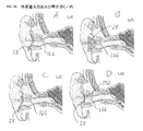
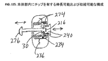
本発明の一態様の実施形態は、対象者の外耳道の内部の画像を取得する撮像装置を対象とする。この実施形態による撮像装置は、本体部と、対象者の外耳道内に挿入される構造を有するように構成された中心軸を有する伸長部とを有する。前記撮像装置は、前記外耳道内に挿入された前記伸長部の前記中心軸に対して所定の角度を成しているか、および/または前記中心軸からオフセットされた画像を取得する構造を有するように構成された撮像素子を有する。あるいは前記撮像装置は、前記伸長部の中心軸と一直線上にある画像を取得するように構成されてもよいが、この場合、前記伸長部は前記外耳道の中心軸に対してオフセットされているとともに所定の角度を成しているか、または前記外耳道の中心軸に対してオフセットされているか若しくは所定の角度を成している。さらに、前記撮像装置は、前記伸長部の前記中心軸に対して所定の角度を成しているか、および/または前記中心軸からオフセットされた画像を取得するとともに、前記外耳道の中心軸に対して所定の角度を成しているか、および/または当該外耳道の中心軸からオフセットされた画像を取得してもよい。本体部および/または伸長部は外耳または外耳道に装着され、これらの位置に適合可能である。 An embodiment of one aspect of the present invention is directed to an imaging device that acquires an image inside the ear canal of a subject. The imaging device according to this embodiment includes a main body portion and an extending portion having a central axis configured to have a structure inserted into the subject's external auditory canal. The imaging device has a structure that forms an angle with respect to the central axis of the extension portion inserted into the ear canal and / or acquires an image offset from the central axis. It has a configured image sensor. Alternatively, the imaging device may be configured to acquire an image that is in a straight line with the central axis of the extension unit. In this case, the extension unit is offset with respect to the central axis of the ear canal. It forms a predetermined angle, or is offset with respect to the central axis of the ear canal or forms a predetermined angle. Further, the imaging device obtains an image that is at a predetermined angle with respect to the central axis of the extension and / or is offset from the central axis, and that is relative to the central axis of the ear canal Images may be acquired that are at a predetermined angle and / or that are offset from the central axis of the ear canal. The main body part and / or the extension part are attached to the outer ear or the ear canal and can be adapted to these positions.
撮像装置は、使用中に対象者の耳または頭部によって支持される構造を有するように構成された装着部材を有してもよく、これにより、ユーザ、提供者、または介護者は装置を所定位置に支持または保持する必要がなくなる。 The imaging device may have a mounting member configured to have a structure that is supported by the subject's ear or head during use, whereby the user, provider, or caregiver determines the device. There is no need to support or hold in place.
撮像装置は、取得画像を処理またはコンピュータ装置に無線送信するための、無線送信素子を有する。あるいは撮像装置は、有線接続を通じて処理またはコンピュータ装置と通信してもよい。例示的なコンピュータ装置の非限定的なリストは、携帯電話、スマートフォン、ラップトップコンピュータ、タブレットコンピュータ、デスクトップコンピュータ、サーバ、メインフレーム、および専用ハードウェアコンピュータ装置を含む。これらの装置は、iOS(Apple Inc.(アップル社)より)およびAndroid(Google Inc.(グーグル社)より)などのモバイル・オペレーティング・システム、OSX(Apple Inc.(アップル社)より)およびWindows(登録商標)(Microsoft Corp.(マイクロソフト社)より)などのデスクトップ・オペレーティング・システム、またはその他いずれかのタイプのオペレーティングシステムまたはプラットフォームを使用して動作することができる。コンピュータ装置はまた、特に撮像装置と使用するために、カスタム設計および製造されることも可能である。 The imaging device includes a wireless transmission element for processing or wirelessly transmitting an acquired image to a computer device. Alternatively, the imaging device may communicate with the processing or computer device through a wired connection. A non-limiting list of exemplary computing devices includes mobile phones, smart phones, laptop computers, tablet computers, desktop computers, servers, mainframes, and dedicated hardware computing devices. These devices include mobile operating systems such as iOS (from Apple Inc.) and Android (from Google Inc.), OSX (from Apple Inc.), and Windows (from Apple Inc.). It can operate using a desktop operating system such as registered trademark (from Microsoft Corp.), or any other type of operating system or platform. Computer devices can also be custom designed and manufactured, especially for use with imaging devices.
撮像装置の伸長部分は、対象者の外耳道内に伸長部を挿入している間に対象者の快適さを改善するために、柔らかい外面を有することができる。 The elongated portion of the imaging device can have a soft outer surface to improve the subject's comfort while inserting the extension into the subject's external ear canal.
本発明の別の態様の実施形態は、おしゃぶり形の口内撮像装置を対象とする。撮像装置は、対象者の口腔の画像を撮像するように構成された撮像素子と、前記画像を処理またはコンピュータ装置に送信するための送信素子とを有する。 Another embodiment of the present invention is directed to a pacifier-type intraoral imaging device. The imaging device includes an imaging device configured to capture an image of a subject's oral cavity, and a transmission device for processing or transmitting the image to a computer device.
本発明の別の態様の実施形態は対象者の診断情報を収集するためのキットを対象とする。キットの異なる実施形態は異なるコンポーネントを包含するものの、有用な組み合わせは、本体部および1若しくはそれ以上の装着部材を有する。前記本体部は、対象者の医療診断情報を取得するための、処理要素および/または計算要素などの診断機器と、有線または無線接続を通じて診断情報をコンピュータ装置に送信する送信素子とを有する。 Another embodiment of the present invention is directed to a kit for collecting diagnostic information of a subject. Although different embodiments of the kit include different components, a useful combination has a body portion and one or more mounting members. The main body includes a diagnostic device such as a processing element and / or a calculation element for acquiring medical diagnosis information of a subject, and a transmission element that transmits the diagnostic information to a computer device through a wired or wireless connection.
本体部用の有用な第一の装着部材は、対象者の外耳道および/または鼓膜を撮像する構造を有するように構成された撮像素子を有する。本体部用の有用な第二の装着部材は、対象者の口腔および/または咽喉を撮像する構造を有するように構成された撮像素子を有する。キットはまた、対象者の身体の内部音声を取得する構造を有するように構成された、音声アクセス素子を有する第三の装着部材も有することができる。キットは、第一のおよび/または第二のおよび/または第三の装着部材のいずれの組み合わせを有することができる。 A useful first mounting member for the main body has an imaging element configured to have a structure for imaging the ear canal and / or eardrum of the subject. A useful second mounting member for the main body has an imaging device configured to have a structure for imaging the subject's oral cavity and / or throat. The kit can also include a third mounting member having a voice access element configured to have a structure for acquiring an internal voice of the subject's body. The kit can have any combination of first and / or second and / or third mounting members.
キット中の送信素子は、装置が使用されているときにリアルタイムで診断情報を送信するように構成されてもよく、あるいは診断情報は、ユーザまたは提供者からの指示の受信とともに送信されてもよい。送信素子は、複数の画像解像度、画像サイズ、または通信速度、あるいはこれらの組み合わせにおいて、診断情報を送信する能力を有する。たとえば、送信素子は、VGA、SVGA、HVGA、または別の解像度で画像を、あるいは12フレーム毎秒、24フレーム毎秒、または別のフレームレートで動画を、送信するように構成されることが可能である。 The transmitting element in the kit may be configured to transmit diagnostic information in real time when the device is in use, or the diagnostic information may be transmitted with receipt of instructions from a user or provider. . The transmitting element has the ability to transmit diagnostic information at multiple image resolutions, image sizes, or communication speeds, or combinations thereof. For example, the transmitting element can be configured to transmit an image at VGA, SVGA, HVGA, or another resolution, or a video at 12 frames per second, 24 frames per second, or another frame rate. .
本体部など、キットのコンポーネントのいずれも、使用中にハンズフリーユニットとして、あるいは使用中にハンドヘルドユニットとして構成されることが可能である。 Any of the components of the kit, such as the body, can be configured as a hands-free unit during use or as a handheld unit during use.
本発明の別の態様は、健康管理専門家によって遠隔的に医療情報を対象者に提供する方法を提供し、この方法は、
a.リモート接続を通じて、前記対象者の現在の医療データを健康管理専門家に提供する工程と、
b.前記対象者の病歴を前記健康管理専門家に選択的に提供する工程と、
c.前記現在の医療データ、および入手可能であれば病歴に基づいて、前記対象者の現在の健康状態の評価を健康管理専門職に行わせる工程と、
d.電子通信チャンネルを通じて前記評価を前記対象者または前記対象者の介護者に送信する工程と
を有する。
Another aspect of the invention provides a method for providing medical information to a subject remotely by a health care professional, the method comprising:
a. Providing the subject's current medical data to a health care professional through a remote connection;
b. Selectively providing the subject's medical history to the health care professional;
c. Allowing a health care professional to evaluate the subject's current health status based on the current medical data and, if available, medical history;
d. Transmitting the evaluation to the subject or the caregiver of the subject through an electronic communication channel.
前記方法はまた、(限定されるものではないが)前記健康管理専門家によって、前記対象者または前記対象者の介護者に治療情報を提供する工程も含んでよい。治療指示は、薬剤の処方箋または検査法を対象者に提供するなど、いずれかのタイプの医学的助言または指示、医療提供者、薬局、病院、または検査室を訪問するための道案内を含むことができる。複数の関係者に複数の指示を与えることも可能である。たとえば、健康管理専門家は、(a)対象者の介護者に口頭の医療指示を提供、(b)薬局に調剤用の処方箋を提供、および(c)検査室に、対象者が特定の種類の検査を受ける必要がある旨の事前通知を提供することができる。 The method may also include (but is not limited to) providing treatment information to the subject or a caregiver of the subject by the health care professional. Treatment instructions include any type of medical advice or instructions, such as providing the subject with drug prescriptions or tests, directions to visit a health care provider, pharmacy, hospital, or laboratory Can do. It is also possible to give a plurality of instructions to a plurality of parties concerned. For example, a health care professional may (a) provide verbal medical instructions to a caregiver of the subject, (b) provide a prescription for dispensing to a pharmacy, and (c) provide a specific type of subject to the laboratory. Can provide advance notice that you need to be examined.
本発明の別の態様は、健康管理提供者による医療情報を対象者に遠隔的に提供する方法を対象とし、この方法は、
a.リモート接続を通じて、訓練を受けていないまたは訓練を一部受けた消費者に、検査装置を用いて対象者の状態についての検査プロトコルを実行するための指示を提供する工程であって、前記検査装置は、非同期環境または遠隔治療環境で使用される現在の対象者医療データを記憶および/または送信するものである、前記提供する工程と、
b.前記消費者により、検査プロトコルデータを前記健康管理提供者に送信する工程と、
c.前記検査装置によって取得されたデータに基づいて、前記対象者の現在の健康状態の評価を前記健康管理提供者に行わせる工程と;
d.前記リモート接続を通じて、前記評価を前記対象者または対象者の介護者に通信する工程と
を有する。
Another aspect of the present invention is directed to a method of remotely providing medical information to a subject by a health care provider, the method comprising:
a. Providing instructions to a non-trained or partially trained consumer via a remote connection to perform a test protocol on the subject's condition using the test device, the test device Providing and / or transmitting current subject medical data for use in an asynchronous or telemedicine environment;
b. Sending test protocol data to the health care provider by the consumer;
c. Causing the health care provider to evaluate the current health status of the subject based on the data acquired by the testing device;
d. Communicating the assessment to the subject or a caregiver of the subject through the remote connection.
前記方法は、さらに、前記健康管理専門家によって、前記対象者または対象者の介護者に対象者についての治療情報を提供する工程も含んでよい。 The method may further include providing treatment information about the subject to the subject or a caregiver of the subject by the health care professional.
前記検査プロトコルデータは、データが取得されたときにリアルタイムで、あるいはたとえばこのデータに関する提供者または健康管理専門家からの指示または要求の受信時に、リアルタイムではなく、前記健康管理提供者に送信されることが可能である。このような実施形態において、検査プロトコルデータは、本発明の実施に加わっている装置内のフラッシュドライブなどの記憶媒体に記憶されることが可能である。検査プロトコルデータはまた、コンピュータ装置に保存することもでき、またはリアルタイムで提供される健康管理による検索若しくは命令の発行のためにクラウドベースのデータ記憶設備に更新されることもできる。 The test protocol data is sent to the health care provider in real time when the data is acquired, or not in real time, for example upon receipt of an instruction or request from a provider or health care professional regarding this data It is possible. In such an embodiment, the inspection protocol data can be stored on a storage medium such as a flash drive in an apparatus participating in the practice of the present invention. The test protocol data can also be stored on a computer device or updated to a cloud-based data storage facility for health care retrieval or issuance of instructions provided in real time.
本発明の別の態様の実施形態は、対象者の状態についての検査プロトコルを実行する検査装置を対象とし、この検査装置は、
a.前記対象者の身体の所定領域に適用される構造を有するように構成された解剖学的インターフェースと;
b.前記対象者の身体に解剖学的インターフェースを適用した後に前記対象者の現在の医療データを取得するアクセスおよび捕捉コンポーネントと;
c.前記アクセスおよび捕捉コンポーネントによって取得された前記医療データを処理する診断処理コンポーネントと;
d.通信リンクであって、医療提供者による閲覧および解釈のために、当該通信リンクを通じて処理された医療データが通信コンポーネントに送信されるものである、前記通信リンクと
を有することができる。
An embodiment of another aspect of the invention is directed to an inspection device that performs an inspection protocol for a subject's condition, the inspection device comprising:
a. An anatomical interface configured to have a structure applied to a predetermined region of the subject's body;
b. An access and capture component that obtains current medical data of the subject after applying an anatomical interface to the subject's body;
c. A diagnostic processing component that processes the medical data acquired by the access and capture component;
d. A communication link, wherein the medical data processed through the communication link is transmitted to the communication component for viewing and interpretation by a health care provider.
解剖学的インターフェースは、前記対象者の耳、鼻、咽喉、目、手首、皮膚、頭部、皮膚、四肢、胴に、あるいは口または鼻の内部などの身体開口部内に適用される構造を有するように構成されている。このようにして、装置の解剖学的インターフェースは、正確な対象者病状情報の提供を容易にする。 The anatomical interface has a structure that is applied to the subject's ear, nose, throat, eyes, wrist, skin, head, skin, limbs, torso, or within a body opening such as inside the mouth or nose. It is configured as follows. In this way, the anatomical interface of the device facilitates providing accurate subject condition information.
開示された装置、システム、またはコンポーネントのいずれも、前記通信リンクを通じて医療提供者または介護者によって遠隔的に送信された制御信号に応答する構造を有するように構成された遠隔制御コンポーネントを有することができる。前記通信リンクは、静止画像、動画配信、音声配信、データストリーム、またはこれらの組み合わせの形態の取得医療データを、医療提供者に送信することができる。 Any of the disclosed devices, systems, or components may have a remote control component configured to have a structure that responds to control signals remotely transmitted by a healthcare provider or caregiver over the communication link. it can. The communication link can transmit acquired medical data in the form of still images, video distribution, audio distribution, data streams, or a combination thereof to a health care provider.
開示された装置、システム、またはコンポーネントのいずれも、携帯電話、ラップトップコンピュータ、タブレットコンピュータ、またはデスクトップコンピュータなどのコンピュータ装置への取付のために構成されたポートまたはジャックを有することができる。ポートまたはジャックは、ミニジャック、USBポート、Apple iDeviceポート(iPhone(登録商標)またはiPad(登録商標)など)などの従来型であってもよく、あるいは製造業者によってカスタム設計されてもよい。 Any of the disclosed devices, systems, or components can have a port or jack configured for attachment to a computing device such as a cell phone, laptop computer, tablet computer, or desktop computer. The port or jack may be conventional, such as a mini jack, USB port, Apple iDevice port (such as iPhone® or iPad®), or may be custom designed by the manufacturer.
本発明のアクセスおよび捕捉コンポーネントの例は、携帯電話、ラップトップコンピュータ、タブレットコンピュータ、デスクトップコンピュータ、またはカスタム設計ハードウェア要素を含む。 Examples of access and capture components of the present invention include mobile phones, laptop computers, tablet computers, desktop computers, or custom designed hardware elements.
本発明の診断処理コンポーネントの例は、携帯電話、ラップトップコンピュータ、タブレットコンピュータ、デスクトップコンピュータ、またはカスタム設計ハードウェア要素を含む。本発明の特定の実施形態において、前記アクセスおよび捕捉コンポーネントと前記診断処理コンポーネントは、同じハードウェア要素であってもよい。つまり、ハードウェア要素は、本明細書において議論および提供されるような、複数の機能を有することができる。 Examples of diagnostic processing components of the present invention include mobile phones, laptop computers, tablet computers, desktop computers, or custom designed hardware elements. In certain embodiments of the invention, the access and capture component and the diagnostic processing component may be the same hardware element. That is, a hardware element can have multiple functions as discussed and provided herein.
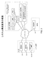
本発明の別の態様の実施形態は、対象者の医学的状態の遠隔診断のための遠隔医療システムを対象とし、この遠隔医療システムは、
A.対象者の現在の医療データを受信するように構成されたユーザサブシステムであって、
1.通信装置と、
2.診断処理装置と、
3.診断捕捉装置と
を有するものである、前記ユーザサブシステムと、
B.健康管理提供者と通信するように構成された提供者サブシステムであって、
1.通信装置
を有するものである、前記提供者サブシステムと、
C.前記ユーザサブシステムおよび前記提供者サブシステムから受信した医療データおよび診断情報を処理および記憶するように構成されたインフラストラクチャサブシステムであって、
1.コンピュータ命令コードを有するアプリケーションサーバであって、
a.対象者の個人情報および電子カルテを記憶するように構成されたデータベース、
b.現在の対象者医療情報を受信して、前記対象者の医学的状態に関する診断情報を提供するように構成された診断コンピュータ命令コード、および
c.アーカイブされた診断情報を記憶するように構成されたデータベースと、
通信するように構成されたコンピュータ命令コードを有するアプリケーションサーバと、
2.1若しくはそれ以上の第三者対象者個人情報または電子カルテデータベースと通信するように構成されたコンピュータ命令コードを有するサーバと、
3.第三者遠隔医療システムと通信するように構成されたコンピュータ命令コードを有するサーバと
を有するものである、前記インフラストラクチャサブシステム
などの要素を有することが可能であり、
前記ユーザ、前記提供者、および前記インフラストラクチャサブシステムは、電子データネットワークを通じて情報をやりとりする構造を有するように構成されている。
An embodiment of another aspect of the invention is directed to a telemedicine system for remote diagnosis of a subject's medical condition, the telemedicine system comprising:
A. A user subsystem configured to receive current medical data of a subject,
1. A communication device;
2. A diagnostic processing device;
3. Said user subsystem comprising: a diagnostic capture device;
B. A provider subsystem configured to communicate with a health care provider;
1. The provider subsystem, comprising a communication device;
C. An infrastructure subsystem configured to process and store medical data and diagnostic information received from the user subsystem and the provider subsystem;
1. An application server having a computer instruction code,
a. A database configured to store the subject's personal information and electronic medical records;
b. A diagnostic computer instruction code configured to receive current subject medical information and provide diagnostic information regarding the subject's medical condition; and c. A database configured to store archived diagnostic information;
An application server having computer instruction code configured to communicate;
A server having computer instruction code configured to communicate with personal information or electronic medical record database of 2.1 or more third party subject personal information;
3. A server having computer instruction code configured to communicate with a third party telemedicine system, and having elements such as the infrastructure subsystem,
The user, the provider, and the infrastructure subsystem are configured to have a structure for exchanging information through an electronic data network.
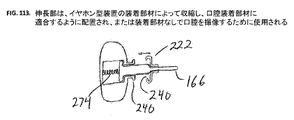
本発明の別の態様は、対象者の体腔内の画像を取得する撮像装置であって、本体部と、前記体腔内に挿入する構造を有するように構成された中心軸を有する伸長部と、前記伸長部からの視点からの画像の捕捉を容易にする構造を有するように構成された撮像素子とを有する撮像装置を対象とする。本発明の実施形態において、前記体腔は前記対象者の外耳道である。 Another aspect of the present invention is an imaging device that acquires an image in a body cavity of a subject, a main body portion, and an extension portion having a central axis configured to be inserted into the body cavity. An imaging device including an imaging device configured to have a structure that facilitates capturing of an image from a viewpoint from the extension unit. In an embodiment of the present invention, the body cavity is the ear canal of the subject.
本発明の別の態様は、少なくとも1つの解剖学的インターフェースを有し、装置が対象者の身体に適用されたときに、前記装置または前記対象者の組織を位置決めし、位置合わせしまたは安定させる構造を有するように構成された医療診断装置を対象とする。 Another aspect of the invention has at least one anatomical interface to position, align or stabilize the device or the subject's tissue when the device is applied to the subject's body. A medical diagnostic apparatus configured to have a structure is a target.
本発明の別の態様は、少なくとも1つの解剖学的インターフェースを有し、装置が対象者の身体に適用されるときに、前記装置または前記対象者の組織を位置決めし、位置合わせしまたは安定させる構造を有するように構成された医療診断装置用の装着部材を対象とする。 Another aspect of the invention has at least one anatomical interface to position, align or stabilize the device or the subject's tissue when the device is applied to the subject's body. A mounting member for a medical diagnostic apparatus configured to have a structure is a target.
本発明の別の態様は、少なくとも1つの解剖学的インターフェースを有し、装置が対象者の身体に適用されたときに、前記装置または前記対象者の組織を位置決めし、位置合わせしまたは安定させる構造を有するように構成された医療診断装置であって、前記解剖学的インターフェースは、前記対象者の身体に適用されたときに診断要素の位置を調整するための可変長を有する伸長自在な構造を有する医療診断装置を対象とする。 Another aspect of the invention has at least one anatomical interface to position, align or stabilize the device or the subject's tissue when the device is applied to the subject's body. A medical diagnostic device configured to have a structure, wherein the anatomical interface has a variable length for adjusting the position of a diagnostic element when applied to the subject's body A medical diagnostic apparatus having
本発明の別の態様は、少なくとも1つの解剖学的インターフェースを有し、装置または装着部材が適用されたときに、前記装置または前記対象者の組織を位置決めし、位置合わせしまたは安定させる構造を有するように構成された医療診断装置用の装着部材であって、前記解剖学的インターフェースは、前記対象者の身体に適用されたときに診断要素の位置を調整するための可変長を有する伸長自在な構造を有する医療診断装置用の装着部材を対象とする。 Another aspect of the invention comprises a structure having at least one anatomical interface for positioning, aligning or stabilizing the device or the subject's tissue when the device or mounting member is applied. A mounting member for a medical diagnostic device configured to have the anatomical interface having a variable length for adjusting the position of a diagnostic element when applied to the subject's body It is intended for a mounting member for a medical diagnostic apparatus having a simple structure.
本発明の別の態様は、対象者の口腔または咽喉に適用される構造を有するように構成された撮像装置であって、使用中に前記口腔内に配置される光入射部および/または出射部を有する撮像装置を対象とする。 Another aspect of the present invention is an imaging device configured to have a structure applied to the oral cavity or throat of a subject, and a light incident part and / or an emission part arranged in the oral cavity during use An imaging apparatus having
本発明の別の態様は、対象者の口腔または咽喉に適用される構造を有するように構成された撮像装置用の装着部材であって、前記口腔内に配置された光入射部および/または出射部を有する撮像装置用の装着部材を対象とする。 Another aspect of the present invention is a mounting member for an imaging apparatus configured to have a structure applied to the oral cavity or throat of a subject, and includes a light incident portion and / or an emission member disposed in the oral cavity. A mounting member for an imaging apparatus having a portion is a target.
本発明の別の態様は、装置を位置決めおよび/または前記装置の正しい位置を確認するようにユーザを支援する構造を有するように構成されたカメラを有する聴診装置を対象とする。 Another aspect of the invention is directed to an auscultation device having a camera configured to have a structure that assists a user to position the device and / or verify the correct position of the device.
本発明の別の態様は、聴診器装着部材を位置決めおよび/または前記聴診器装着部材の正しい位置を確認するようにユーザを支援する構造を有するように構成されたカメラを有する装置用の聴診器装着部材を対象とする。 Another aspect of the present invention is a stethoscope for a device having a camera configured to have a structure to assist a user to position a stethoscope mounting member and / or verify the correct position of the stethoscope mounting member. For mounting members.
本発明の別の態様は、外耳道または鼓膜の撮像のために対象者の前記外耳道に配置する構造を有するように構成された医療装置であって、使用中に前記対象者の外耳を実質的に操作することなく前記外耳道または前記鼓膜の画像を取得するように構成された医療装置を対象とする。 Another aspect of the present invention is a medical device configured to be positioned in the ear canal of a subject for imaging of the ear canal or tympanic membrane, wherein the outer ear of the subject is substantially in use during use. It is intended for a medical device configured to acquire an image of the ear canal or the eardrum without operation.
本発明の別の態様は、外耳道または鼓膜の撮像のために対象者の前記外耳道に配置する構造を有するように構成された医療装置用の装着部材であって、使用中に前記対象者の外耳を実質的に操作することなく前記外耳道または前記鼓膜の画像を取得するように構成された医療装置用の装着部材を対象とする。 Another aspect of the present invention is a mounting member for a medical device configured to be disposed in the ear canal of a subject for imaging of the ear canal or the eardrum, and the outer ear of the subject during use. An attachment member for a medical device that is configured to acquire an image of the ear canal or the eardrum without substantially manipulating the object is intended.
定義
簡便性のために、以下の用語に関してさらなる情報を下記に提供する。本明細書中のその他および均等の用語は、類似の概念を記載するために使用される。
For definitional convenience, further information regarding the following terms is provided below. Other and equivalent terms herein are used to describe similar concepts.
対象者:健康上の助言を望むかまたは必要とする、1若しくはそれ以上の個人。単数(A)は、たとえばエクササイズクラスまたはスポーツチームなど、グループであってもよい。 Subject: One or more individuals who want or need health advice. The singular (A) may be a group, for example an exercise class or a sports team.
介護者:健康問題について対象者を支援する、1若しくはそれ以上の個人。この個人は通常、たとえば息子または娘または親またはコーチなど、対象者の知り合いである。 Caregiver: One or more individuals who assist the subject with health problems. This individual is usually an acquaintance of the subject, for example a son or daughter or a parent or coach.
ユーザ:1若しくはそれ以上の対象者および/または介護者。 User: One or more subjects and / or caregivers.
健康専門家:健康または関連分野において資格または経験のある、いずれかの個人。例として、医師、外科医、看護師、医師助手(PA)、ナースプラクティショナ(NP)、理学療法士、栄養士、研修医、救急医療隊員、EMTなどを含む。 Health professional: Any individual who is qualified or experienced in health or related fields. Examples include physicians, surgeons, nurses, physician assistants (PA), nurse practitioners (NP), physiotherapists, nutritionists, residents, emergency medical personnel, EMT, and the like.
ナースホットライン:健康上の助言を提供する、または個人を適切な健康専門家につなげるのを支援する、保険会社または健康関連事業体によって提供されるサービス。 Nurse Hotline: A service provided by an insurance company or health-related entity that provides health advice or helps connect individuals with appropriate health professionals.
コールセンター:健康上の助言を提供する、または個人を適切な健康専門家につなげるのを支援する、非健康関連事業体によって提供されるサービス。 Call center: A service provided by a non-health entity that provides health advice or helps connect an individual with the appropriate health professional.
提供者:1若しくはそれ以上の健康専門家、ナースホットライン、および/またはコールセンター。 Provider: One or more health professionals, a nurse hotline, and / or a call center.
様々な例示的実施形態の説明
本明細書の開示は詳細であって、当業者が本発明を実践できるほど正確であるものの、本明細書に開示される物理的実施形態は本発明を例示するのみであって、これは明確に記載されるやり方で実現されることが可能である。好適な実施形態が記載されているものの、本発明から逸脱することなく詳細が変更されてもよく、これは本明細書に記載される様々な開示および請求項によって定義されている。
DESCRIPTION OF VARIOUS EXEMPLARY EMBODIMENTS Although the disclosure herein is detailed and accurate enough to enable those skilled in the art to practice the invention, the physical embodiments disclosed herein exemplify the invention. This can only be realized in a clearly described manner. While preferred embodiments have been described, details may be changed without departing from the invention, which is defined by the various disclosures and claims set forth herein.
本開示は、現在の診断装置に存在する安全性、耐性、快適性または有用性の問題を軽減または排除し、ユーザが最小限しかまたはまったく訓練を受けていないとしても、より容易且つ快適な体験を可能にする装置、方法、システムおよび特徴を述べて記載する。好ましい装置の設計は、医師の診察室においてみられる器具と同じ機能を果たすが、子供および親の両方にとってより使い慣れたおよび/またはより快適な形態および形状にパッケージ化される。これらの特徴は、医療機器によって自然に脅かされる感覚を通常は有する対象者(特に子供)の緊張を軽減し、また、使い慣れた快適な装置を使用している自信を有するユーザの緊張を軽減する。 The present disclosure mitigates or eliminates the safety, tolerance, comfort or usability issues that exist with current diagnostic devices, making the experience easier and more comfortable even if the user has received minimal or no training An apparatus, method, system, and features that enable this are described and described. The preferred device design performs the same function as an instrument found in a doctor's office, but is packaged in a form and shape that is more familiar and / or more comfortable for both children and parents. These features reduce the tension of subjects (especially children) who usually have a sense that is naturally threatened by medical devices, and also reduce the tension of confident users using familiar and comfortable devices .
I.耳、口腔および咽喉の適切な解剖学的構造
このような解剖学的特徴を参照して本発明の実施形態が記載されるため、耳、口腔および咽喉の適切な解剖学的構造の簡単な概要を提供することは有用であろう。
I. Proper anatomy of the ear, mouth and throat Since embodiments of the present invention are described with reference to such anatomical features, a brief overview of the proper anatomy of the ear, mouth and throat It would be useful to provide
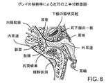
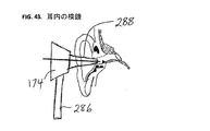
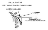
A.外耳および外耳道
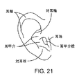
1.外耳解剖学的構造
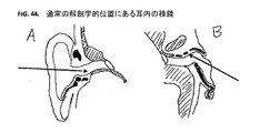
外耳は、鼓膜または耳介と呼ばれる耳の可視部分、ならびに鼓膜(tympanic membrane)または鼓膜(ear drum)の外面につながる外耳道(external acoustic meatus)または外耳道(ear canal)から成る(図8、図9、図21を参照)。鼓膜は半透明であり、中耳の一部は膜を介して視覚化することができる。最も顕著な特徴は槌骨である。鼓膜の状態および槌骨を視認する能力は、大抵の場合、耳の問題を診断するために使用される。不健康な耳では、鼓膜は、その外見が膨らんだり曇ったりすることがあり、槌骨を区別することが困難であるかもしれない。耳の視認部は、外耳とも呼ばれる。耳介は、甲介、耳珠、対珠および対耳輪ならびに他の特徴を含む。甲介は、耳の椀状部分であり、外耳道につながっている。耳珠は甲介の前方にあり、対珠は甲介の下方にある。対珠は甲介の後方ならびに上方に位置している。耳甲介腔は、外耳道につながる甲介の内側部分である。
A. Outer ear and
以下の開示および本文において、耳の可視部分が意図されているかどうか、または外耳道も含む外耳全体にも議論が適用可能であるかどうかについては、一般に明らかであろう。しかしながら、詳細な説明の文脈が考慮されるべきである。 In the following disclosure and text, it will generally be clear whether the visible portion of the ear is intended or whether the discussion is applicable to the entire outer ear, including the ear canal. However, the context of the detailed description should be considered.
2.外耳道
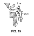
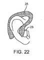
外耳道は、一般に楕円形であり、入口で最大である。外耳道は、S字状に湾曲しており、第1部分では上方および後方(上および後)を向き、次いで下方および前方(下および前)に移動している。外耳道は、新生児ではより真っ直ぐであり、成長によって徐々に成人の外耳道の一般的な形状を帯び、外耳道は、一般に、12ヶ月後に成人と同様に形成される。外耳道の入口は、一般に、成人の場合、垂直方向(下方/上方向)に9mm且つ水平方向(前方/後方向)に6.5mmの範囲にある。外耳道の長さは、乳児では約1.5cmから成人では約2.5cmまで変化する。そして、外耳道の直径は、成人では約6〜7mm、乳児では3mmの平均直径に減少する。外耳道は、軟骨部と骨部とから成る。軟骨部は、新生児ではほぼ全長に延在し、成人では最初の約1/3の長さに延在する。この外耳道の外側部分は、耳垢が分泌される場所と同様に、より長い毛髪が位置する場所である。図39Aは、耳の様々な部分ならびに外耳道の湾曲を示す、耳および外耳道の水平または横断面(上または上方の半分が示されている)である。外耳道は、図39Aに示すように、最初に、後方(後)に伸び、次いで前方(前)に伸びる。外耳道の水平(前方/後方)寸法は、全長にわたって同様であるように示されており、成人では平均で約6〜7mmである。
2. The external auditory canal The external auditory canal is generally elliptical and is largest at the entrance. The external auditory canal is curved in an S-shape, and in the first part, faces upward and backward (up and back) and then moves downward and forward (down and forward). The ear canal is straighter in newborns and gradually takes on the general shape of the adult ear canal as it grows, and the ear canal is generally formed in the same way as an adult after 12 months. The entrance to the ear canal is typically in the range of 9 mm vertically (down / up) and 6.5 mm horizontally (forward / back) for adults. The length of the ear canal varies from about 1.5 cm in infants to about 2.5 cm in adults. And the diameter of the ear canal is reduced to an average diameter of about 6-7 mm for adults and 3 mm for infants. The ear canal is composed of a cartilage portion and a bone portion. The cartilage extends approximately the entire length in newborns, and extends to about the first third of the length in adults. The outer part of the ear canal is where longer hair is located, similar to where the earwax is secreted. FIG. 39A is a horizontal or cross-sectional view of the ear and ear canal showing the various parts of the ear and the curvature of the ear canal (top or top half shown). The ear canal first extends backward (back) and then forward (front) as shown in FIG. 39A. The horizontal (anterior / posterior) dimensions of the ear canal are shown to be similar over the entire length, with an average of about 6-7 mm in adults.
図39Bは、正面または冠状断面(後または後方の半分が示されている)であり、外耳道の上方および下方(上および下)の形状を示している。外耳道の始端部分は、この断面ではより大きな寸法を有する。開始垂直(下方/上方)の寸法は、成人では平均約9mmであり、外耳道の残りの長さが約6〜7mmまで減少する。断面は、両方向における外耳道の湾曲に起因して外耳道の中心を示す正確な正面および横断面ではないことが特筆される。 FIG. 39B is a frontal or coronal section (rear or posterior half shown) showing the upper and lower (upper and lower) shapes of the ear canal. The beginning portion of the ear canal has a larger dimension in this cross section. The starting vertical (lower / upper) dimension averages about 9 mm in adults and the remaining length of the ear canal is reduced to about 6-7 mm. It is noted that the cross section is not an exact front and cross section showing the center of the ear canal due to curvature of the ear canal in both directions.
B.口、咽喉および口腔検査
1.口または口腔
口または口腔の主な構造は、歯、舌および口蓋である(図40A、図40Bを参照)。口腔は、前または前端において唇によって外側に接続され、後または後端において中咽頭(咽喉の一部)に接続している。口腔は、2つの部分、前庭および固有口腔から成る。前庭は、歯、唇および頬の間の領域である。頬の内側には頬粘膜が並んでいる。口腔の上部および後部の一部は、口腔および鼻腔を隔てる口蓋によって形成される。口蓋の前部または前方の3分の2は、硬口蓋であり、後部または後方の3分の1は軟口蓋である。口蓋垂は、軟口蓋の中央から下方に伸びている。舌の上部または上方の表面は、背と呼ばれる。背の前部の2/3は口腔の一部である。口腔は、3つの主要な唾液腺とともに、口を湿らせて身体を健康に保つために唾液を作る多くの小腺を含む。これらの腺は、口を潤滑し、嚥下を助け、細菌に対して歯を保護し、食物の消化を助ける。
B. Mouth, throat and oral examination Mouth or oral cavity The main structure of the mouth or oral cavity is the teeth, tongue and palate (see FIGS. 40A and 40B). The oral cavity is connected to the outside by lips at the front or front end and to the oropharynx (part of the throat) at the rear or rear end. The oral cavity consists of two parts, the vestibule and the proper oral cavity. The vestibule is the area between the teeth, lips and cheeks. The buccal mucosa is lined up inside the cheek. The upper and rear part of the oral cavity is formed by the palate separating the oral cavity and the nasal cavity. The front or front two-thirds of the palate is the hard palate, and the rear or rear one-third is the soft palate. The uvula extends downward from the center of the soft palate. The upper or upper surface of the tongue is called the back. 2/3 of the front part of the back is part of the oral cavity. The oral cavity, along with three major salivary glands, contains many small glands that make saliva to moisten the mouth and keep the body healthy. These glands lubricate the mouth, help swallowing, protect the teeth against bacteria, and help digest food.
2.中咽頭(咽喉の一部)
口腔は、中咽頭と呼ばれる咽喉の一部に後部において接続されている(図40A、図40Bを参照)。中咽頭は、鼻腔に接続する上部において鼻咽頭に接続されている。中咽頭の底部または下方境界は、その場所で下咽頭(咽喉頭とも呼ばれる)が始まる喉頭蓋によって画定される。中咽頭の側部または側方の壁は、扁桃柱によって画定される三角形の凹部を含む。前部(前方)の柱は口蓋弓と呼ばれ、後部(後方)の柱は口蓋咽頭弓と呼ばれる。口蓋扁桃、または単なる扁桃腺は、中咽頭の側壁のこの三角形の凹部内に含まれる。中咽頭または咽喉の後壁は、後咽頭壁と呼ばれる。舌表面(背)の後部若しくは後方の3分の1、または舌の基部は、中咽頭の前部または前側の一部を形成する。
2. Oropharynx (part of throat)
The oral cavity is connected at the rear to a part of the throat called the oropharynx (see FIGS. 40A and 40B). The oropharynx is connected to the nasopharynx at the top connecting to the nasal cavity. The bottom or lower boundary of the oropharynx is defined by the epiglottis where the hypopharynx (also called the pharynx) begins. The lateral or lateral wall of the oropharynx includes a triangular recess defined by the tonsillar column. The anterior (anterior) column is called the palatal arch, and the posterior (posterior) column is called the palatopharyngeal arch. The palatine tonsils, or just the tonsils, are contained within this triangular recess in the sidewall of the oropharynx. The posterior wall of the oropharynx or throat is called the posterior pharyngeal wall. The posterior or posterior third of the tongue surface (dorsal), or the base of the tongue forms the front or part of the front of the oropharynx.
3.口内検査
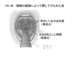
多くの構造は、医療専門家が全体的な健康状態を判定して状態を診断するのを助けるために口を介して視覚化されることができる。歯ならびに頬、歯肉および舌の粘膜の一般的な状態は、大抵の場合、医師の診察室において検査される。軟口蓋、扁桃腺、口蓋垂、咽喉の後壁および咽喉の開口部の状態および大きさは、大抵の場合、風邪、インフルエンザ、咽喉痛、連鎖球菌性咽頭炎または扁桃炎などの多くの症状を示す、診断するまたは鑑別するのに有用である。これらの構造はまた、舌の大きさとともに、気道の大きさを判定する際にも重要であり、睡眠時無呼吸などの睡眠状態が存在するかどうかを判定するのに役立つように検査されることができる。
3. Oral Examination Many structures can be visualized through the mouth to help medical professionals determine overall health status and diagnose the condition. The general condition of the teeth and the mucous membranes of the cheeks, gums and tongue is often examined in a doctor's office. The condition and size of the soft palate, tonsils, uvula, posterior wall of the throat and throat opening usually indicate many symptoms such as cold, flu, sore throat, streptococcal pharyngitis or tonsillitis, Useful for diagnosing or differentiating. These structures are also important in determining the size of the airway, as well as the size of the tongue, and are examined to help determine whether a sleep condition such as sleep apnea exists. be able to.
II.現在の装置および診断方法
A.装置および方法の使いやすさ、安全性、耐性
1.安全性および耐性
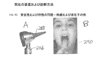
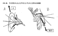
現在の診断装置および方法は、大抵の場合、不快であり、且つ、特に熟練した専門家ではなく経験の浅い消費者の手にある場合に忍容性および安全性の問題を引き起こす可能性のある、脅威のあるインターフェースを組み込む。これらのインターフェースの例は、検鏡および舌圧子である(図41を参照)。舌圧子は、通常、咽喉および扁桃腺などの構造の視界を通常遮断する舌を押し下げるために、口腔および咽喉をみるときに使用される。それらは不快であり、特に家庭で使用する場合、たとえば、圧子があまりにも遠くに挿入されている場合または子供が頭を素早く動かして圧子が咽喉の後部に当たる場合、安全性の問題を引き起こす可能性がある。検鏡は、鼓膜を視覚化するために外耳道内に挿入される耳鏡における円錐形の伸長部である。検鏡は、一般的には、外耳道内を毛髪および耳垢を越えて確認するために外耳道内を十分に遠くに挿入される。外耳道の壁は、特に耳感染症が存在する場合には、繊細且つ敏感である。外耳道の長さの最後の2/3を伸びる外耳道の骨部は、特に繊細且つ敏感であり、検鏡の先端部などの物体によって損傷を受ける可能性がある。耐性の問題は、鼓膜をみるのを非常に困難にする可能性があり、時にはそれはまったく不可能である。この状況は、怖れて非協力的な低年齢の子供において最も一般的である。
II. Current devices and diagnostic methods Ease of use, safety and resistance of the device and method Safety and Tolerance Current diagnostic devices and methods are often uncomfortable and cause tolerability and safety problems, especially in the hands of inexperienced consumers rather than skilled professionals Incorporate possible and threatening interfaces. Examples of these interfaces are a speculum and a tongue depressor (see FIG. 41). Tongue depressors are usually used when looking at the mouth and throat to depress the tongue, which normally blocks the view of structures such as the throat and tonsils. They are uncomfortable and can cause safety problems, especially when used at home, for example if the indenter is inserted too far away or if the child moves the head quickly and the indenter hits the back of the throat There is. A speculum is a conical extension in an otoscope that is inserted into the ear canal to visualize the eardrum. The speculum is generally inserted far enough into the ear canal to see the ear canal beyond the hair and wax. The wall of the ear canal is delicate and sensitive, especially when ear infections are present. The bones of the ear canal that extend the last two thirds of the length of the ear canal are particularly delicate and sensitive and can be damaged by objects such as the tip of a speculum. The problem of tolerance can make it very difficult to see the eardrum, and sometimes it is not possible at all. This situation is most common in scared and uncooperative young children.
これらの不快な装置を強制的に使用することは、少なくとも軽度の外傷性の体験を引き起こすことがあり、同様の状況が現れたときの体験および協力の拒否の記憶のために将来子供の診断をさらに困難にすることがある。これらの問題は、医師や看護師などの提供者によって行われるように訓練および練習によって部分的に克服されるかもしれないが、消え失せることはない。この訓練および練習は、看護師または医師などの提供者にとって実用的であるが、潜在的な利益をさらに上回る可能性がある危険性および問題のために大多数の消費者からそのような訓練を期待するのは現実的ではない。さらに、現在の診断装置の設計は、本質的に不快であり且つ感覚を脅かすようにみえることがある脅威のあるインターフェースを有する、使い慣れていないものである(診察室器具に似ている)。子供は、通常、そのような装置に慎重であり、それらを怖がり、親または他のユーザは、それらを使用することに自信を持っていない。訓練および練習は、不快な体験をせいぜい生み出す根本的な要因を排除するものではない。 Forced use of these unpleasant devices can cause at least a mild traumatic experience, and future child diagnoses can be used to remember experiences and similar refusals when similar situations appear. It can be even more difficult. These problems may be partially overcome by training and practice as done by providers such as doctors and nurses, but cannot be lost. Although this training and practice is practical for providers such as nurses or doctors, it does not provide such training from the majority of consumers because of the risks and problems that may even outweigh the potential benefits. It is not realistic to expect. In addition, current diagnostic device designs are unfamiliar (similar to examination room equipment) with a threatening interface that is inherently unpleasant and can appear to threaten the senses. Children are usually cautious about such devices and scare them, and parents or other users are not confident in using them. Training and practice does not eliminate the fundamental factors that at best create an unpleasant experience.
2.使いやすさ
現在の装置は、一般的には使用するのが困難であり、通常は訓練および練習を必要とする。耳鏡によって鼓膜を撮像するために、いくつかの変数が制御される必要がある。互いに相対的に移動する3つの部分(頭部、耳および耳鏡)がある。外耳道を真っ直ぐにするために耳を頭部に対して引き戻すように片手が使用される。他方の手は、耳鏡を保持して位置決めするために使用される。頭部に対する耳および耳鏡の位置を維持するために、片手は、大抵の場合に頭部に対して且つ通常は同様に他方の手に保持されている耳鏡に対して支持される。これらの変数のすべては、検鏡の先端部(外耳道内に挿入される耳鏡の部分)の向きおよび深さとともに、装置を安全に使用して鼓膜を撮像するためにユーザによって調整および制御される。ユーザは、鼓膜がみえるかどうかを知るために、レンズまたは画面をみながらこれらの移動部分の位置を確認するまたは感じることができなければならない。これは、説明するのが困難なほどの操作であり、実行するのはもちろんのこと、通常は訓練、練習、および「感じる」ことが必要である。
2. UTILIZATION Current devices are generally difficult to use and usually require training and practice. In order to image the eardrum with an otoscope, several variables need to be controlled. There are three parts (head, ear and otoscope) that move relative to each other. One hand is used to pull the ear back against the head to straighten the ear canal. The other hand is used to hold and position the otoscope. In order to maintain the position of the ear and otoscope with respect to the head, one hand is supported relative to the otoscope that is usually held against the head and usually also in the other hand. All of these variables, along with the orientation and depth of the tip of the microscope (the part of the otoscope inserted into the ear canal), are adjusted and controlled by the user to safely use the device to image the eardrum. The The user must be able to see or feel the position of these moving parts while looking at the lens or screen to see if the eardrum is visible. This is an operation that is difficult to explain and of course requires training, practice, and “feeling” as well as performing.
図42A〜図42Bは、使用中の耳鏡を示している。ユーザの左手は、指のうちのいくつかを上方の首に対して支持しながら耳を引っ張って外耳道を真っ直ぐにしている。耳鏡は、右手で保持されており、また、左手に対して支持されながら、ユーザは、視野をみながら検鏡の向きおよび深さを制御する。この手順は、若くて怖れている子供はもちろんのこと、(図42に示すように)成人に対して十分行うのが困難である。訓練を受けた専門家でさえも、特定の場合にはこれらの変数を管理することが困難な場合がある。 42A-42B show the otoscope in use. The user's left hand pulls the ear while supporting some of the fingers against the upper neck to straighten the ear canal. While the otoscope is held by the right hand and supported by the left hand, the user controls the direction and depth of the speculum while viewing the visual field. This procedure is difficult to perform well for adults (as shown in FIG. 42) as well as young and afraid children. Even trained professionals can have difficulty managing these variables in certain cases.
口腔および咽喉を撮像する場合にも同様の困難が存在する。口は開いたままであり、舌は押さえられ(通常、図41Bに示すように舌圧子を使用して達成される)、撮像装置は、ユーザがファインダを介してまたは画面上でみているとき所望の解剖学的構造を捕捉するように向けられる(図46を参照)。この場合、変数は、頭部の位置、顎の位置、舌の位置および装置の位置、ならびに場合によっては口蓋の位置を含む。ユーザまたは医療提供者はまた、通常は光を口および咽喉に照射しながら、自身の肉眼によって装置または対象者の口腔を検査することもできる。 Similar difficulties exist when imaging the oral cavity and throat. The mouth remains open, the tongue is pressed down (usually achieved using a tongue depressor as shown in FIG. 41B), and the imaging device is in a desired state when the user is looking through the viewfinder or on the screen. Oriented to capture anatomy (see FIG. 46). In this case, the variables include head position, chin position, tongue position and device position, and possibly the palate position. The user or health care provider can also examine the device or the subject's oral cavity with his own naked eye, usually irradiating the mouth and throat with light.
B.既存の診断機器による鼓膜の可視化および耳感染症の診断
1.概要
上述したように、現在の耳鏡は、検鏡と呼ばれる円錐形の伸長部を有するハンドヘルド装置から成る。鼓膜を視覚化するために、外耳道を真っ直ぐにするために耳を引き戻しおよび引き上げる。12ヶ月未満の乳児では、外耳道がより真っ直ぐであるため、耳が引き戻されて下がることがある。そして、検鏡の先端部が外耳道内に挿入されて鼓膜を視覚化する。検鏡をあまりにも遠くに挿入しないようにするとともに外耳道の壁に対する先端部の圧力を避けるように注意する必要がある。検鏡は、鼓膜までの真っ直ぐな視界を得るために、検鏡の軸を耳の鼓膜の方に向けるために移動されて曲げられる。耳鏡は、通常、鼓膜を拡大してみることができるように倍率を有し、視野が限られているため、位置合わせをさらに困難にする。耳鏡は、通常、片手で保持され、手の一部が頭部または頬に当てて装置を安定させながら他方の手は耳を引っ張って外耳道を真っ直ぐにする。ユーザは、鼓膜をみるために練習して熟練する必要がある。特に耳感染症が存在するときには耳がより敏感であることから、迅速に且つ可能な限り快適に作業を実行する技能がさらに重要である。子供は、不快感や煩わしさ、装置および/または医師の診察室の怖れ、および大抵の場合に非協力的なために検査するのが特に困難である。装置および検鏡は、脅威であると認識されている、使い慣れておらず且つ脅威のある装置である。
B. Visualization of eardrum and diagnosis of ear infections using existing diagnostic equipment Overview As described above, current otoscopes consist of a handheld device with a conical extension called a speculum. In order to visualize the eardrum, the ears are pulled back and raised to straighten the ear canal. In infants younger than 12 months, the ear canal may be pulled back because the ear canal is more straight. The tip of the speculum is inserted into the ear canal to visualize the eardrum. Care should be taken not to insert the speculum too far and to avoid tip pressure against the ear canal wall. The speculum is moved and bent to direct the speculum axis towards the ear tympanic membrane in order to obtain a straight field of view to the ear drum. Otoscopes usually have magnification so that the eardrum can be magnified and have a limited field of view, making alignment even more difficult. The otoscope is usually held in one hand, with one hand resting on the head or cheek to stabilize the device while the other hand pulls the ear to straighten the ear canal. The user needs to practice and become skilled to see the eardrum. Since ears are more sensitive, especially when ear infections are present, skills to perform tasks quickly and as comfortably as possible are even more important. Children are particularly difficult to examine because of discomfort and annoyance, fear of equipment and / or doctors' examination rooms, and in most cases uncooperative. Devices and speculums are unfamiliar and threatening devices that are recognized as threats.
2.検査中の耳の位置および検鏡の位置
矢印を有する実線および破線が、撮像器具の位置および一般的な視線方向を表すために図面において使用される。
2. The position of the ear under examination and the position of the speculum The solid and dashed lines with arrows are used in the drawings to represent the position of the imaging device and the general viewing direction.
図43は、使用中に外耳道内に挿入された検鏡を有する耳鏡を示している。撮像器具、この場合には耳鏡および検鏡の位置は、黒実線によって示されており、一般的な視線方向は、破線および矢印によって示されている。図44、図45は、耳および外耳道の断面と、外耳道内に挿入された検鏡の位置/角度とを示しており、円錐形の検鏡の位置は、黒実線によって示されている。図44Aは、外耳道の上方およびわずかに下方の曲率を示す正面断面図である。図44Bは、耳の水平断面を示しており、外耳道の前湾曲および後湾曲を示している。これらの図は、通常の解剖学的位置にある耳を示している。外耳道内に挿入された検鏡は、一般に、特に拡大装置を用いてこの位置における耳による鼓膜をみるために正確に方向付けされる。これは、検査のために耳が引き戻されおよび引き上げられて外耳道を真っ直ぐにする理由である。外耳道および鼓膜の3D構造に対する撮像器具の適切な位置を判定するために、および鼓膜に向かう、閉塞されていないまたは閉塞された経路があるかどうかを判定するために、双方の2次元ビューが考慮されるべきである。 FIG. 43 shows an otoscope having a microscope inserted into the ear canal during use. The position of the imaging device, in this case the otoscope and the speculum, is indicated by a solid black line, and the general line-of-sight direction is indicated by a broken line and an arrow. 44 and 45 show the cross-sections of the ear and ear canal and the position / angle of the speculum inserted into the ear canal, the position of the conical speculum being indicated by the solid black line. FIG. 44A is a front cross-sectional view showing the curvature above and slightly below the ear canal. FIG. 44B shows a horizontal cross-section of the ear, showing the front and back curves of the ear canal. These figures show the ear in its normal anatomical position. A speculum inserted into the ear canal is generally accurately oriented to view the eardrum by the ear at this location, particularly using a magnifying device. This is why the ear is pulled back and raised for examination to straighten the ear canal. Both two-dimensional views are considered to determine the proper location of the imaging device relative to the 3D structure of the ear canal and eardrum and to determine if there is an unobstructed or obstructed path toward the eardrum. It should be.
図45A、図45Bは、耳鏡検査のために耳が引き戻されおよび引き上げられたときの耳の位置、外耳道の形状および検鏡の位置を示している(幼児の場合、上述した外耳道の異なる形状のために耳が引き戻されまたは引き下げられることができる)。耳を引き戻しおよび引き上げると、検鏡の先端部は、通常、外耳道の軸と位置合わせし且つ鼓膜の視界を提供するために、前向きおよび下向き(前方および下方)に曲げられる。 45A and 45B show the position of the ear, the shape of the ear canal and the position of the speculum when the ear is pulled back and pulled up for otoscopy (in the case of an infant, the different shapes of the ear canal described above). Ears can be pulled back or pulled down). When the ear is pulled back and up, the tip of the speculum is usually bent forward and downward (forward and downward) to align with the ear canal axis and provide a view of the eardrum.
先に記載したように、ユーザが保持する耳鏡に装着された検鏡の角度は、鼓膜をみるために制御されなければならない。大きな破線は、検鏡の方向および位置の変動の例を示している。所望の位置/角度からの小さな変動は、依然として鼓膜の画像が捕捉されるのを可能にするが、ユーザは、所望の角度に近い位置(すなわち、破線によって示されるものよりも小さい変動)を達成して維持しなければならない。耳の鼓膜または外耳道に近いほど敏感である外耳道の壁を傷つけるほどの深さではなく、十分な画像を取得するのに十分な深さに器具があるように、深さもまた制御される必要がある。特に装置の先端部によって外耳道の壁に当たることによって不快感や潜在的な怪我を制限するために、左右および上下の動きもまた制御される必要がある。 As described above, the angle of the speculum attached to the otoscope held by the user must be controlled to view the eardrum. The large broken line shows an example of the direction and position of the speculum. Small variations from the desired position / angle still allow the tympanic image to be captured, but the user achieves a position close to the desired angle (ie, less variation than that shown by the dashed line). Must be maintained. The depth also needs to be controlled so that the instrument is deep enough to acquire sufficient images, not deep enough to damage the ear canal or the ear canal walls that are more sensitive to the ear canal. is there. Left and right and up and down movements also need to be controlled, particularly to limit discomfort and potential injuries by hitting the ear canal wall with the tip of the device.
3.既存の診断器具および技術による咽喉の可視化
人が口を広く開くと、通常みられる特徴は、歯、舌、硬口蓋および軟口蓋の一部である。舌は、通常、視界を咽喉に戻す(図47A、図47Bを参照)。咽喉および扁桃腺の裏側を視覚化するために、通常、医療専門家または親などの他の閲覧者は、通常は閲覧器具によってみながら、口の後ろに光を当て、対象者は、口を開いて、「ああ」と言う(図46を参照)。時には、この行動は、後方咽頭壁(咽喉の後ろ)および扁桃腺を確認するために十分に舌を下げて軟口蓋および口蓋垂を上昇させる。しかしながら、大抵の場合、それを咽喉内に通して確認するために舌を押し下げるように舌圧子を使用する必要がある。この場合、舌圧子の適切な位置決めが重要である。それは、咽喉内の視界を閉塞している舌のその部分を押し下げるように十分後方に配置されなければならないが、咽頭反射を生じさせるほど遠くには配置されてはならない。図48は、使用中の舌圧子ならびに咽喉および扁桃腺の図を示している。
3. Visualization of the throat with existing diagnostic instruments and techniques When a person opens his mouth wide, features commonly seen are parts of the teeth, tongue, hard palate and soft palate. The tongue usually returns the field of view to the throat (see FIGS. 47A, 47B). To visualize the back of the throat and tonsils, other viewers, usually a health care professional or parent, usually shine light behind the mouth while looking through the viewing device, and the subject Open and say “Oh” (see FIG. 46). Sometimes this behavior raises the soft palate and uvula sufficiently to lower the tongue to identify the posterior pharyngeal wall (behind throat) and tonsils. However, in most cases it is necessary to use a tongue depressor to push the tongue down to see it through the throat. In this case, proper positioning of the tongue depressor is important. It must be placed posterior enough to push down that part of the tongue that obstructs the view in the throat, but not far enough to cause a pharyngeal reflex. FIG. 48 shows a diagram of the tongue depressor and throat and tonsils in use.
舌を押さえることは、通常、不快な体験である。それは、大抵の場合、(なおも不快ではあるが)年長児や成人において日常的に行うことができるが、低年齢の子供は、大抵の場合、特に病気や咽喉痛がある場合には協力的ではない。さらに、経験の浅い人は、咽頭反射を生じさせずに咽喉を確認するために舌を十分に押さえることが困難な場合があり、または、さらに悪いことに、特に咽喉内にすべての方法で挿入される場合、舌圧子を使用しているときに組織への損傷を誘発することがある。経験の浅い人もまた、咽喉を確認しようとする時間および回数が増え、対象者に不快感または苦痛を与えることがある。 Holding the tongue is usually an unpleasant experience. It can usually be done on a daily basis in older children and adults (although it is still uncomfortable), but younger children often cooperate, especially if they have illness or sore throat Not right. In addition, inexperienced people may find it difficult to hold the tongue well to see the throat without creating a pharyngeal reflex, or worse, all the way, especially into the throat If done, it may induce tissue damage when using a tongue depressor. Inexperienced people can also experience increased discomfort or pain in the subject, increasing the time and frequency of trying to check the throat.
III.遠隔医療システム:概要
本発明は、従来技術の診断視覚化方法に関連する問題を解消するか、または少なくとも大幅に低減する。様々な実施形態において、開示されたシステムおよび方法は、複数の時間または条件において対象者情報を収集する能力を含み、それによって情報は、医療専門家によって送信および/またはアクセスされ、対象者の状態の評価に使用されることができる。
III. Telemedicine System: Overview The present invention eliminates or at least significantly reduces the problems associated with prior art diagnostic visualization methods. In various embodiments, the disclosed systems and methods include the ability to collect subject information at multiple times or conditions so that the information is transmitted and / or accessed by a health care professional and subject status Can be used for evaluation.
本明細書に記載される様々な図は、健康問題の遠隔診断のための、様々な遠隔医療および/またはその他のシステムを描写している。これらの例示的システムは以下に続く章に記載される多くの異なる要素を含む一方で、このようなシステムのその他様々な実施形態はまた、ユーザによって望まれ、本開示によって想起される通りに、追加のまたはこれより少ない要素を含んでもよいことが、理解されるべきである。これらのより単純または複雑なシステムのうちのいくつかは、後に論じられる。 The various figures described herein depict various telemedicine and / or other systems for remote diagnosis of health problems. While these exemplary systems include many different elements described in the following chapters, various other embodiments of such systems are also desired by the user and as envisioned by this disclosure, It should be understood that additional or fewer elements may be included. Some of these simpler or more complex systems are discussed later.
A.導入および例示的なシステム
図1は、本発明による例示的な遠隔医療システムを示している。消費者は、たとえばテレビ電話を使用して健康状態に関する助言または診断を要求するために医療提供者に連絡する。消費者は、問題を説明し、背景健康情報を提供する。そして、消費者は、装置を使用して診断情報を収集して提供者に送信する。提供者は、モニタまたは表示画面の一部にこの情報をライブ表示するとともに、また、モニタまたは表示画面の残りの部分で消費者を確認して通信する。利用可能なデータ速度に応じて、収集される情報よりも低解像度で情報が送信されてもよい。より高解像度のデータは、さらに収集されてユーザ側で維持されることができ、動画の選択されたセグメントまたは全長は、ライブ送信中またはライブ送信後に提供者に送信されることができる(図2を参照)。提供者は、情報およびデータを確認し、消費者が診察室に来る要求、対象者が異なる提供者にみてもらうための紹介、または薬剤の処方箋を含むことができる助言または診断を提供する。
A. Introduction and Exemplary System FIG. 1 illustrates an exemplary telemedicine system according to the present invention. The consumer contacts the health care provider to request health advice or diagnosis using, for example, a videophone. The consumer explains the problem and provides background health information. The consumer then collects diagnostic information using the device and sends it to the provider. The provider displays this information live on a portion of the monitor or display screen, and also communicates with confirmation of the consumer on the remainder of the monitor or display screen. Depending on the available data rate, the information may be transmitted at a lower resolution than the collected information. Higher resolution data can be further collected and maintained on the user side, and a selected segment or total length of the video can be transmitted to the provider during or after live transmission (FIG. 2). See). The provider verifies the information and data and provides advice or diagnosis that may include a request for the consumer to come to the examination room, referrals for the subject to be seen by a different provider, or a prescription for the drug.
システム(図3を参照)は、一般的には、以下のサブシステム、1)ユーザシステム、2)提供者システム、ならびに3)物流およびインフラストラクチャシステムのうちの1若しくはそれ以上から成る。たとえば、ユーザは、スマートフォンなどの通信装置上でソフトウェアアプリケーションを開く。このソフトウェアは、アプリケーションサーバに接続されたデータベースに情報が記憶されている提供者とのインターネットを介したリンクをユーザがさらに確立するのを可能にするアプリケーションサーバとインターネット上のリンクを確立する。ユーザの情報および健康記録はまた、サーバを介して取得されることもできる。そして、ユーザは、タブレット、スマートフォン、ラップトップまたはデスクトップコンピュータなどの装置を使用している提供者と通信することができる。提供者は、ユーザの鼓膜の画像などの追加の診断情報を要求することができる。そして、ユーザは、インターネットを介して情報を記憶するアプリケーションサーバに対して情報を送信して提供者に中継する診断装置を用いてこれらの画像を捕捉する。ユーザおよび提供者は、テレビ電話を介して通信することができ、提供者は、リアルタイムで診断情報を視認しおよび/または診断装置の態様(たとえば、ズーム、カメラの角度調整、照明の調整など)を遠隔的に制御することができる。 The system (see FIG. 3) generally consists of one or more of the following subsystems: 1) a user system, 2) a provider system, and 3) a logistics and infrastructure system. For example, the user opens a software application on a communication device such as a smartphone. The software establishes a link on the Internet with the application server that allows the user to further establish a link over the Internet with a provider whose information is stored in a database connected to the application server. User information and health records can also be obtained via the server. The user can then communicate with a provider using a device such as a tablet, smartphone, laptop or desktop computer. The provider can request additional diagnostic information such as an image of the user's eardrum. Then, the user captures these images using a diagnostic device that transmits information to an application server that stores information via the Internet and relays the information to a provider. The user and the provider can communicate via a video phone so that the provider can view diagnostic information in real time and / or aspects of the diagnostic device (eg, zoom, camera angle adjustment, lighting adjustment, etc.) Can be controlled remotely.
B.システムの他の例
ユーザは、助言または診断を提供するソフトウェアによって分析される画像または動画を収集することができる。このソフトウェアは、スマートフォンなどのユーザの装置にローカルに存在することができ、または、サーバ上に遠隔的に存在することもできる。ソフトウェアによって生成された仮想提供者は、ユーザと通信することができる。
B. Other Examples of Systems A user can collect images or videos that are analyzed by software that provides advice or diagnosis. This software can reside locally on a user's device, such as a smartphone, or can reside remotely on a server. The virtual provider generated by the software can communicate with the user.
複数の提供者が関与してもよい。たとえば、提供者は、ユーザおよび提供者と通信する専門家に情報を転送してもよい。あるいは、専門家または他の追加の提供者は、一次提供者とユーザとの間の通信に参加し、すべての関係者がリアルタイムで診断情報をみてもよい。 Multiple providers may be involved. For example, a provider may transfer information to a user and an expert who communicates with the provider. Alternatively, an expert or other additional provider may participate in communication between the primary provider and the user, and all parties may view diagnostic information in real time.
所定の状態が存在する場合、状態を監視し、ユーザまたは提供者に警告するために、システムが使用されてもよい。ユーザは、この情報を定期的に収集することができ、または、装置は、ユーザの入力なしに情報を継続的または定期的に収集することができる。そして、提供者は、特定の状態が通知されると、ユーザとの連絡を開始することができる。 If a predetermined condition exists, the system may be used to monitor the condition and alert the user or provider. The user can collect this information periodically, or the device can collect information continuously or periodically without user input. And a provider can start a contact with a user, if a specific state is notified.
ユーザは、入力または助言のために、友人、家族または他のユーザに情報を送信することができる。この情報は、ユーザがその後にフィードバックを提供するシステム上のユーザのグループまたはすべてのユーザに送信されることができる。このような送信は、医療情報の共有に関する適用可能な規則に従って行われる。 The user can send information to friends, family or other users for input or advice. This information can be sent to a group of users or all users on the system for which the user subsequently provides feedback. Such transmissions are made according to applicable rules for sharing medical information.
C.通信コンポーネントおよび1若しくはそれ以上のユーザおよび/または提供者の遠隔連結
遠隔医療システムは好ましくは、通信装置を通じて1若しくはそれ以上の関係者を遠隔的に連結し、音声、動画、および/またはテキスト通信を可能にする方法を含む。あるいはシステムは、ユーザが動画、音声、テキスト、背景健康情報、および/または診断情報を記録および/またはアップロードできるようにし、提供者がユーザとライブ通信することなく診断または助言を評価および提供できるようにするために、通信装置を採用してもよい。
C. Remote connection of communication components and one or more users and / or providers The telemedicine system preferably connects one or more parties remotely through a communication device to provide voice, video and / or text communication. Including methods to enable Alternatively, the system allows the user to record and / or upload video, audio, text, background health information, and / or diagnostic information so that the provider can evaluate and provide diagnostics or advice without live communication with the user In order to achieve this, a communication device may be employed.
通信コンポーネントは、様々な形態を取ることができる。たとえば、ユーザは、コンピュータ、タブレット、固定電話、標準的な携帯電話、AppleのiPhone(登録商標)などのスマートフォン、遠隔医療システムとの使用に特化された固有の通信装置、または音声、動画、テキスト、ファイル、および/または診断情報の記録、送信、および/またはアップロードを可能にするその他いずれかの装置と、通信することができる。様々な実施形態において、装置は望ましくは、類似情報の受信を許容し、ユーザが提供者からの診断または助言を受信できるようにする。1つの実施形態において、提供者通信コンポーネントは、類似の設計および能力のものである。他の実施形態において、ユーザおよび提供者は、さらに通信して利用可能である場合にテキスト/音声/データの共有を可能にする異種の通信装置およびコンポーネントを有することができる。 The communication component can take a variety of forms. For example, a user may be a computer, tablet, landline phone, standard mobile phone, smartphone such as Apple's iPhone®, a unique communication device specialized for use with telemedicine systems, or voice, video, It can communicate with any other device that allows the recording, transmission, and / or uploading of text, files, and / or diagnostic information. In various embodiments, the device desirably allows reception of similar information and allows a user to receive diagnosis or advice from a provider. In one embodiment, the provider communication component is of similar design and capability. In other embodiments, users and providers can have disparate communication devices and components that allow text / voice / data sharing when further communicated and available.
望ましくは、提供者通信装置は、ユーザからの情報を受信し、診断または助言をユーザに送信することが可能となる。ユーザおよび/または提供者は、2つ以上の通信装置を同時にまたは連続的に使用することができる。たとえばユーザは、提供者と音声で通信するために固定電話を使用し、診断情報を送受信するためにコンピュータを使用することができる。診断情報を送信する装置は通信装置を有する(または通信装置である)ことも可能である一方で、これはまた、通信装置から分離されることが可能な診断プロセッサとしても記載される。 Desirably, the provider communication device can receive information from the user and send diagnostics or advice to the user. A user and / or provider can use two or more communication devices simultaneously or sequentially. For example, a user can use a landline phone to communicate with a provider by voice and a computer to send and receive diagnostic information. While a device that transmits diagnostic information can have a communication device (or be a communication device), it is also described as a diagnostic processor that can be separated from the communication device.
ユーザと提供者間のリンクは、様々な方法を用いて形成されることが可能である。ユーザは、診療要求を提出することによって遠隔医療セッションを開始することができる。この要求は、特定の提供者(たとえば、対象者の一次診療医)、限られたネットワークの提供者を対象とし、あるいはこれはいずれか利用可能な提供者に「クラウド−ソーシング」されることが可能であり、これによってより迅速な応答を容易にする。加えて要求は、予備評定を提供し、必要に応じて医者または医師などの適切な提供者に接続を転送することができる、ナースホットラインまたはコールセンターに送られてもよい。 The link between the user and the provider can be formed using various methods. A user can initiate a telemedicine session by submitting a medical request. This request is directed to a specific provider (eg, the subject's primary care physician), a limited network provider, or may be “cloud-sourced” to any available provider. Yes, which facilitates a quicker response. In addition, the request may be sent to a nurse hotline or call center that provides a preliminary rating and can forward the connection to a suitable provider such as a doctor or physician if necessary.
提供者はその後診療要求を受け付け、様々な実施形態において、ユーザと提供者間で安全なリンクが確立されることが可能である。このリンクは電話のように単純であるが、しかしより望ましくはユーザと提供者間の動画リンクを含む。また、先に述べられたように、安全なリンクは情報(たとえば動画、音声、および/または診断情報)の送信のみを包含し、「リアルタイム」ライブ通信を必要としない。診断情報、および/または記録された音声および動画送信などのその他の情報は、提供者、および/またはユーザおよびユーザに転送された診断または助言から切り離されたソフトウェア解析ツールによって、検討される。 The provider then accepts the medical request and, in various embodiments, a secure link can be established between the user and the provider. This link is as simple as a telephone, but more preferably includes an animated link between the user and the provider. Also, as mentioned earlier, secure links only involve the transmission of information (eg, video, audio, and / or diagnostic information) and do not require “real time” live communication. Diagnostic information and / or other information such as recorded audio and video transmissions are reviewed by the provider and / or software analysis tools separated from the user and the diagnosis or advice transferred to the user.
D.診断情報および関連病歴の収集および送信
提供者はその後、ユーザからの関連既往歴、およびユーザが助けを求めている健康問題の説明を、収集および/または検討する。この情報の一部またはすべてがユーザのアカウントに包含されている場合、または遠隔地からの取得に利用可能な場合、ユーザは提供者とこの情報を直接共有するように、および/またはこの記憶済みデータの提供者への公開を承認するように、選択することができる。加えて、最新の(現在の)診断情報を提供者と共有できることがユーザにとって望ましい。この情報は、様々な家庭用診断装置の使用を通じて、最近、時間をかけて、または電話中に、収集されたものであってもよい。対象者情報の例は、血圧読み取り値または血糖値を含むことができる。これらの装置はユーザのみにデータを供給することが可能であり、ユーザはその後このデータを提供者と共有するか、または装置は通信チャンネルを通じてこのデータが提供者に送信されるかまたは直接共有されるのを可能にすることができる。この診断情報はまた、本明細書に記載される診断装置の使用を通じて収集されることも可能である。
D. Collection and transmission of diagnostic information and related medical history The provider then collects and / or reviews a related medical history from the user and a description of the health problem for which the user is seeking help. If some or all of this information is included in the user's account or is available for remote retrieval, the user may share this information directly with the provider and / or this stored You can choose to approve the release of the data to the provider. In addition, it is desirable for the user to be able to share the latest (current) diagnostic information with the provider. This information may have been collected recently, over time, or on the phone, through the use of various home diagnostic devices. Examples of subject information can include blood pressure readings or blood glucose levels. These devices can only supply data to the user and the user can then share this data with the provider, or the device can transmit this data to the provider or communicate directly through the communication channel. Can be made possible. This diagnostic information can also be collected through the use of the diagnostic devices described herein.
理想的には診断装置は、提供者に診断データの1若しくはそれ以上の配信を、および(適用可能であれば)、高解像度またはより正確な情報が検討されるようにするために診断配信を制御または精緻化あるいはスナップショットまたはセグメントをダウンロードする能力を提供する、通信チャンネルに接続される。関連する既往歴情報はまた、スマートフォンGPSおよび/またはクレジットカードからの地理的位置データ、電子財布からの支払情報など、診断装置または連結された装置に記憶された、またはこれらから別途取得された情報またはデータも、含むことができる。 Ideally, the diagnostic device will provide the provider with one or more distributions of diagnostic data, and (if applicable) diagnostic distribution to ensure that high resolution or more accurate information is considered. Connected to a communication channel that provides the ability to control or refine or download snapshots or segments. Related medical history information is also stored in or obtained separately from diagnostic devices or connected devices, such as geographic location data from smartphone GPS and / or credit cards, payment information from electronic wallets, etc. Or data can also be included.
次の工程は、提供者が診断を決定するかまたはユーザに助言を与える工程である。これは、電子処方箋(ユーザからのGPS地理情報を用いて特定される地元薬局への指示を含むことができる)、再診の予約、および/またはユーザを診察室、応急手当、または緊急処置室に向かうよう推奨すること(対象者の場所に基づく地元のサービス提供者への指示を含むことができる)を含むことができる。ユーザおよび提供者はその後、十分な解決に到達したことを認める。解決に納得がいかない場合、十分な結果に到達するのを支援するため、第三者に問い合わせてもよい。 The next step is that the provider decides on a diagnosis or gives advice to the user. This may include an electronic prescription (which may include directions to a local pharmacy identified using GPS geo-information from the user), appointments for revisiting, and / or the user in an examination room, first aid, or emergency room (Which may include instructions to local service providers based on the subject's location). The user and provider then acknowledge that a satisfactory solution has been reached. If you are not satisfied with the solution, you may contact a third party to help you reach a satisfactory result.
この例示的システムの下での対象者ケアの最終工程は、診察の終了(たとえば対象者ケア指示の提供)および物流の完了を包含することができる。これは、対象者回収のための電子処方箋の提出、支払の処理、電話の詳細または概要を含む電子リンクまたは電子メール、および/または保険記入用紙またはその他の正式書類の作成および提出を、含むことができる。 The final steps of subject care under this exemplary system can include the completion of the examination (eg, providing subject care instructions) and the completion of the logistics. This includes the submission and submission of electronic prescriptions for subject collection, payment processing, electronic links or emails containing telephone details or summaries, and / or the creation and submission of insurance forms or other formal documents. Can do.
E.アカウント、物流、およびインフラストラクチャ
様々な実施形態において、通信の開始に先立って、何らかのタイプの1若しくはそれ以上のユーザアカウントが作成されることが、好ましい。望ましくは、ユーザアカウントは、対象者またはその他の責任者が提供者へのアクセスの料金を支払うことができることを証明するのに十分な情報を、包含すべきである。このアカウントは、できるだけ支払情報のみを包含する、匿名性のものであり、あるいは対象者履歴に関する詳細な情報および/または対象者の電子カルテ(Electronic Health Record:EHR)へのリンクを包含することができる。望ましくは、提供者アカウントは、要求されたケアを提供するために、自身の身元および専門知識を保証するのに十分な情報を、包含すべきである。このアカウントは、医師グループ、保険会社、またはその他類似の責任あるグループによって確立および維持される、より大きいアカウントの一部であってもよい。
E. Accounts, Logistics, and Infrastructure In various embodiments, it is preferred that some type of one or more user accounts be created prior to communication initiation. Preferably, the user account should contain sufficient information to prove that the subject or other responsible person can pay for access to the provider. This account may be anonymous, containing only payment information as much as possible, or may contain detailed information about the subject history and / or a link to the subject's Electronic Health Record (EHR). it can. Desirably, the provider account should contain sufficient information to ensure its identity and expertise to provide the required care. This account may be part of a larger account established and maintained by a physician group, an insurance company, or other similar responsible group.
F.遠隔医療システムおよび付加的な特徴
遠隔医療システムに組み込まれることが可能な、いくつかのタイプのシステムおよび特徴がある。遠隔医療システムは、ユーザと提供者間の通話のように簡単であり、あるいはビデオ会議、および装置を用いてユーザによってリアルタイムで捕捉される画像などの診断データのライブ送信を含む。システムはまた、テキストおよびファイルの共有、ならびに対象者の電子カルテ(Electronic Health Record:EHR)へのリンクおよび更新も、可能にする。提供者は単に忠告を与えるかまたは正式診断を提供し、そして電子処方箋を送信する。システムはまた、たとえば特定の状態の確率をユーザに与えるために、あるいはより完全な解析を提供者に提供するために、診断データのコンピュータ解析を組み込むことが可能である。
F. Telemedicine systems and additional features There are several types of systems and features that can be incorporated into a telemedicine system. Telemedicine systems are as simple as a call between a user and a provider, or include video conferencing and live transmission of diagnostic data such as images captured in real time by the user using the device. The system also allows text and file sharing, as well as linking and updating to the subject's Electronic Health Record (EHR). The provider simply gives advice or provides a formal diagnosis and sends an electronic prescription. The system can also incorporate computer analysis of diagnostic data, eg, to give a user a probability of a particular condition, or to provide a more complete analysis to the provider.
ある場所の介護者、第二の場所の対象者、および1若しくはそれ以上の提供者を同じ「通話」で接続する能力を含む、複数のタイプの接続が記載される。ユーザは、順位付けに基づいて特定の医師を選択して適切に支払を行うか、または特定の金額を申し出てその料金を受け入れる提供者を待ってもよい。社会的/ゲーム/教育的要素がシステムに組み込まれていてもよい。たとえばユーザは、別のユーザからのコメントおよび忠告を求めて自身の健康問題を「クラウドソーシング」することを望むかも知れない。ユーザは、別のユーザへの自身のフィードバックにおいて特定レベルの正確さを達成するため、値引きを提案されるかも知れない。システムは、健康上の疾患の例を伴う身体の中または周りのビデオゲーム形三次元ツアー、およびこれらの問題を予防または治療する方法を、含むことができる。ユーザには点数が与えられ、例示的な健康上の疾患の正しい特定に基づいてそのステータスを向上することができる。 Several types of connections are described, including the ability to connect a caregiver at one location, a subject at a second location, and one or more providers in the same “call”. The user may select a specific physician based on the ranking and pay appropriately, or wait for a provider to offer a specific amount and accept the fee. Social / game / educational elements may be incorporated into the system. For example, a user may wish to “crowd” his health problem in search of comments and advice from another user. A user may be offered a discount to achieve a certain level of accuracy in his feedback to another user. The system can include video game-type three-dimensional tours in or around the body with examples of health conditions, and methods for preventing or treating these problems. The user is given a score and can improve their status based on the correct identification of an exemplary health disorder.
IV.遠隔医療システムのコンポーネント
記載される遠隔医療システム、ならびにこれより単純または複雑なシステムを容易にするのを助ける装置、方法、およびシステムのいくつかの実施形態が、本明細書に記載される。診断実施形態は遠隔医療システムを用いずに使用されてもよいこと、ならびに遠隔医療実施形態は診断装置を使用することなく利用されてもよいことは、特筆すべきである。
IV. Telemedicine System Components Described herein are some embodiments of the described telemedicine system, as well as devices, methods, and systems that help facilitate a simpler or more complex system. It should be noted that the diagnostic embodiment may be used without a telemedicine system, and that the telemedicine embodiment may be utilized without using a diagnostic device.
A.遠隔監視および診断のためのユーザサブシステム:概要
本発明の装置、システムおよび方法は、一般的には、消費者による使用の観点から記載されるが、本発明のこのような態様はまた、提供者によって使用されることができる。より良いレンズ、高輝度照明、高解像度ビデオチップ、より敏感なマイクロフォン、データを操作するための追加のオプション(たとえば、画像の修正および音のフィルタリング)などのハイエンド装置およびコンポーネントが、提供者による使用のために組み込まれることが好ましい。また、装置は、設置および場所の制限が少ない熟練した提供者によるより細かな制御を可能にすることが好ましい。たとえば、装置は、提供者が外耳道における伸長部をより大きい程度まで曲げ且つ消費者による使用を意図した類似の装置よりも深く配置するのを可能にすることができる。
A. User Subsystem for Remote Monitoring and Diagnosis: Overview Although the devices, systems and methods of the present invention are generally described in terms of consumer use, such aspects of the present invention also provide Can be used by a person. High-end equipment and components such as better lenses, high-intensity lighting, high-resolution video chips, more sensitive microphones, and additional options for manipulating data (eg, image modification and sound filtering) are used by providers Is preferably incorporated for the purpose. Also, the device preferably allows finer control by a skilled provider with fewer installation and location restrictions. For example, the device may allow the provider to bend the extension in the ear canal to a greater extent and place it deeper than a similar device intended for consumer use.
ユーザシステム(図4を参照)は、一般的には、以下のコンポーネント、1)通信コンポーネント、2)診断データにアクセスおよび/または捕捉するためのコンポーネント、ならびに3)診断情報を処理するためのコンポーネントのうちの1若しくはそれ以上から成る。システムおよびこれらのコンポーネントの多くの構成、ならびに他のコンポーネントおよび特徴も可能である。たとえば、システムは、3つのコンポーネントをすべて含む1つの診断装置を含むことができる。あるいは、システムは、1)アクセスおよび捕捉コンポーネントと診断データの部分的処理(たとえば、スマートフォンへのまたは直接提供者へのデータの送信および/またはデータの記録)のためのコンポーネントとを含む診断装置とともに、2)提供者との音声、動画またはテキスト通信のための通信コンポーネントならびに診断情報の処理(診断装置から受信して提供者に送信するおよび/またはデータを分析する)のためのコンポーネントを含むスマートフォンなどのコンピュータ装置を含むことができる。 A user system (see FIG. 4) generally includes the following components: 1) a communication component, 2) a component for accessing and / or capturing diagnostic data, and 3) a component for processing diagnostic information. Consisting of one or more of Many configurations of the system and these components are possible, as well as other components and features. For example, the system can include one diagnostic device that includes all three components. Alternatively, the system is in conjunction with a diagnostic device that includes 1) an access and capture component and a component for partial processing of diagnostic data (eg, sending data to and / or recording data directly to a smartphone or to a provider) 2) A smartphone including a communication component for voice, video or text communication with a provider and a component for processing diagnostic information (received from a diagnostic device and transmitted to the provider and / or analyzing data) Or other computer devices.
B.通信コンポーネント
通信コンポーネントは、ユーザが他のユーザまたは提供者などの他の関係者と接続して情報を共有し、助言または診断を要求して受信するのを可能にする。例としては、ラップトップ、タブレット、携帯電話またはスマートフォンおよび固定電話を含む。通信は、たとえば、テキスト、音声または動画を介して、1若しくはそれ以上の方法によって行うことができる。
B. Communication component The communication component allows users to connect with other parties such as other users or providers to share information and to request and receive advice or diagnostics. Examples include laptops, tablets, mobile phones or smartphones and landlines. Communication can be performed by one or more methods, for example, via text, audio or video.
C.アクセスおよび捕捉コンポーネント
アクセスおよび捕捉コンポーネントは、一般的には、1)アクセス要素、2)捕捉要素、および3)解剖学的インターフェースのうちの1若しくはそれ以上から成る。アクセスおよび捕捉要素は、診断要素と総称され、診断情報へのアクセスおよび捕捉に使用される。
C. Access and capture component The access and capture component generally consists of one or more of 1) an access element, 2) a capture element, and 3) an anatomical interface. Access and capture elements are collectively referred to as diagnostic elements and are used to access and capture diagnostic information.
1.アクセス要素
アクセス要素は、捕捉要素および身体の領域との間で診断情報を転送する。アクセス要素は、光を光源から物体に向けて伝達するレンズならびに集光して光を捕捉するためにビデオチップに向けて導くレンズなどの入射部および出射部を含む。アクセス要素は、身体の領域と捕捉要素との間において診断情報にアクセスし、収集し、伝達するための任意の手段を含む。これらは、開口チャンネル、反射面および鏡、光ファイバ、レンズ、隔膜、ならびに熱、音、電気、光、運動および磁場を含むエネルギを収集して伝達するための他の手段を含む。アクセス要素はまた、身体の組織または体液のために使用されてもよい。アクセス要素は、形状、質感または他の特性が関心のある身体の領域に適合してもよい。
1. Access element The access element transfers diagnostic information between the capture element and the body region. The access element includes an entrance and exit such as a lens that transmits light from the light source towards the object and a lens that focuses and directs it towards the video chip to capture the light. The access element includes any means for accessing, collecting and communicating diagnostic information between the body region and the capture element. These include aperture channels, reflective surfaces and mirrors, optical fibers, lenses, diaphragms, and other means for collecting and transmitting energy, including heat, sound, electricity, light, motion and magnetic fields. The access element may also be used for body tissue or fluid. The access element may be adapted to a region of the body where shape, texture or other characteristics are of interest.
2.捕捉要素
捕捉要素は、診断関連情報を作成および/または捕捉するために使用される要素を含む。これらは、光源および圧力源などの源要素ならびにビデオチップなどの目標要素を含む。たとえば、LEDは、電気を使用して光を生成し、これを鼓膜に向けて伝達することができる。そして、この光は、情報を処理(記憶、記録、画面上への出力など)される電気に変換するビデオチップ上に光を集束させるレンズに向け吸収または反射される。捕捉要素はまた、たとえば、脳によってその後に処理される光または音を集めるためのユーザまたは提供者の眼または耳とすることができる。指の神経受容器に類似した触感を再現するために力を捕捉するために圧力変換器が使用されてもよい。
2. Capture Elements Capture elements include elements used to create and / or capture diagnostic related information. These include source elements such as light sources and pressure sources and target elements such as video chips. For example, LEDs can use electricity to generate light and transmit it toward the eardrum. This light is then absorbed or reflected towards a lens that focuses the light onto a video chip that converts information into electricity that is processed (stored, recorded, output on the screen, etc.). The capture element can also be, for example, the eye or ear of a user or provider for collecting light or sound that is subsequently processed by the brain. A pressure transducer may be used to capture the force to reproduce a tactile sensation similar to a finger neuroreceptor.
3.解剖学的インターフェース
解剖学的インターフェースは、多くの目的に役立つことができる。一般に、解剖学的インターフェースは、身体の領域に接触し、診断情報へのアクセスおよび捕捉を容易にするのを助ける。たとえば、特徴は、レンズが鼓膜に向けて光を透過させて鼓膜から集光するように耳または外耳道の中または上に適合してレンズを外耳道に位置合わせすることができる。特徴はまた、たとえば、咽喉をみるために舌を押すことによって診断情報がより良く捕捉されるように、解剖学的構造を位置決めするのを助けるために使用されることができる。解剖学的インターフェースはまた、アクセス要素としても機能することができる。たとえば、身体に接触する隔膜またはバルーンの一部は、音を集めて伝達することができる。インターフェースはまた、身体との間で電気を伝導するために使用されることができる。インターフェースはまた、安全性、耐性、快適性にも役立つことができる。
3. Anatomical interface The anatomical interface can serve many purposes. In general, the anatomical interface contacts the body region and helps facilitate access and capture of diagnostic information. For example, the feature can be adapted to align the lens with the ear canal in or on the ear or ear canal such that the lens transmits light toward the eardrum and collects from the eardrum. The feature can also be used to help position the anatomy so that diagnostic information is better captured, for example, by pushing the tongue to see the throat. The anatomical interface can also function as an access element. For example, a diaphragm or part of a balloon that contacts the body can collect and transmit sound. The interface can also be used to conduct electricity to and from the body. The interface can also help with safety, tolerance and comfort.
D.処理コンポーネント
処理コンポーネントは、信号を変換若しくは処理する、または診断情報を送信、受信、記録、または出力する要素を含む。たとえば、画像プロセッサおよび無線チップが耳を撮像するためにイヤホン型装置に含まれてもよい。信号は、ビデオチップによって捕捉された後、処理され、スマートフォンなどのコンピュータ装置に無線送信される。このスマートフォンは、情報を受信して記録し、画面上に表示し、提供者に送信する。イヤホン型装置およびスマートフォンは、両方とも、一般的には処理コンポーネントを有する。
D. Processing Component The processing component includes elements that convert or process signals or send, receive, record, or output diagnostic information. For example, an image processor and a wireless chip may be included in an earphone type device to image the ear. After the signal is captured by the video chip, it is processed and wirelessly transmitted to a computer device such as a smartphone. This smartphone receives and records information, displays it on the screen, and transmits it to the provider. Both earphone devices and smartphones typically have processing components.
V.様々なユーザ装置およびシステムの概要
装置のガイドとして機能する解剖学的インターフェースが提供される。たとえば、イヤホン型装置は、既存の耳鏡および検鏡をガイドするための支持面または貫通孔を有することができる。
V. Overview of Various User Devices and Systems An anatomical interface is provided that serves as a device guide. For example, an earphone-type device can have a support surface or through-hole for guiding existing otoscopes and speculums.
装着部材または消耗品は、既存の器具/装置に設けられる。装着部材の例は以下の通りである:それに成形されたイヤホン型装置などの解剖学的インターフェースを有する検鏡であり、既存の器具に装着されている;イヤホン型装置は、別個に形成され、検鏡上に摺動されるかまたは接続されることができる。標準的なカメラまたはスマートフォンに適合するように構成された湾曲または柔軟性の検鏡;咽喉を撮像するために口腔スコープ上を摺動される風味付けされたスリーブ、または舌圧子または柔らかい外側を有する半硬質舌圧子上に配置された軟性スリーブ。 A mounting member or consumable is provided on an existing instrument / device. Examples of mounting members are as follows: a speculum having an anatomical interface, such as an earphone shaped device molded into it, attached to an existing instrument; the earphone shaped device is formed separately, It can be slid or connected on the speculum. Curved or flexible speculum configured to fit a standard camera or smartphone; has a flavored sleeve that is slid over the oral scope to image the throat, or tongue depressor or soft exterior A soft sleeve placed on a semi-rigid tongue depressor.
診断装置は、診断情報を処理する小さな「ボックス」に配線されている。ボックスに対して装着および取り外されることができる複数の装置が提供されることができる。ボックスは、スマートフォンなどのコンピュータ装置にまたはインターネットを介してサーバに直接情報を送信することができる。このボックスは、いくつかの診断装置(たとえば、口腔装置への無線接続によって)にしっかりと装着されることができ、耳を撮像するための小さなイヤホン型装置などの他の装置に無線接続されることができる。装置はまた、さらなる処理のためにボックスに情報を無線送信することもできる。 The diagnostic device is wired to a small “box” that processes the diagnostic information. Multiple devices can be provided that can be installed and removed from the box. The box can send information directly to a computer device, such as a smartphone, or to a server via the Internet. This box can be securely attached to some diagnostic devices (eg by wireless connection to the oral device) and wirelessly connected to other devices such as a small earphone-type device for imaging the ear be able to. The device can also wirelessly transmit information to the box for further processing.
単一の装置が情報を捕捉して処理することがある。たとえば、耳装置は、耳から画像を捕捉し、その情報を、インターネットを介して直接サーバに送信することができる。あるいは、装置は、スマートフォンなどのコンピュータ装置に情報を送信して、ローカル「ボックス」に情報を出力または記録し、インターネットを介して直接サーバに送信するなどの他の方法で情報を処理することができる。装置はまた、マイクロフォンおよびスピーカなどの通信要素を有してもよい。この装置は、通信のためにBlueTooth(登録商標)経由でスマートフォンにリンクしてもよい。あるいは、「ボックス」は、通信要素を含んでもよく、独立型通信装置として機能するかまたは通信を確立するスマートフォンにリンクされてもよい。 A single device may capture and process information. For example, the ear device can capture an image from the ear and send the information directly to the server via the Internet. Alternatively, the device may process the information in other ways, such as sending information to a computer device such as a smartphone, outputting or recording the information in a local “box” and sending it directly to the server via the Internet. it can. The device may also have communication elements such as a microphone and a speaker. This device may link to a smartphone via BlueTooth® for communication. Alternatively, the “box” may include a communication element and may be linked to a smartphone that functions as a stand-alone communication device or establishes communication.
装置は、身体の1若しくはそれ以上の場所において1若しくはそれ以上の種類の診断情報にアクセスして捕捉するために使用可能であるように、複数の診断要素およびそれに内蔵された解剖学的インターフェースを有することができる。あるいは、装置は、処理要素を有してもよく、診断要素を有する装着部材が提供されてもよく、2つの組み合わせがあってもよい。たとえば、装置には、ビデオチップおよび他のセンサ(たとえば、MEM、または微小電気機械センサ)などの複数の捕捉要素が提供されることができる。装置に内蔵されたいくつかのインターフェースは、一部のセンサを使用して身体から情報を収集するのを可能にする。解剖学的インターフェースを有する他の装着部材は、他の場所でさらなる診断情報にアクセスするのに役立つ。さらに他の装着部材は、情報を捕捉するためのセンサが提供されることができ、解剖学的インターフェースも含むことができる。 The device includes a plurality of diagnostic elements and an anatomical interface incorporated therein so that the apparatus can be used to access and capture one or more types of diagnostic information at one or more locations on the body. Can have. Alternatively, the device may have a processing element, a mounting member having a diagnostic element may be provided, and there may be a combination of the two. For example, the device can be provided with a plurality of capture elements such as video chips and other sensors (eg, MEMs or microelectromechanical sensors). Some interfaces built into the device allow some sensors to be used to collect information from the body. Other mounting members that have an anatomical interface help to access additional diagnostic information elsewhere. Still other mounting members can be provided with sensors for capturing information and can also include an anatomical interface.
VI.通信装置、システム、および方法
A.通信コンポーネント
対象者/介護者通信装置は、いずれの種類の構造を有することも可能であり、理想的には動画、テキスト、ファイル共有、および/またはその他のデータ接続を許容する、遠隔地への接続を許容する装置を含むことができる。複数の通信装置が協力して使用されることも可能である。たとえば、1つの通信装置は動画/音声通信のために使用されてもよく、第二の通信装置は医療サービス提供者に対して診断情報を表示および/または送信するためのチャンネルとして使用されてもよい。また、ユーザは固定電話でさらに快適に会話できるが、医療サービス提供者にデータを送信するためのデータ診断処理ユニットの役割も果たすコンピュータ(通信装置)上で、提供者を見ることもできる。通信装置の例は以下に提供され、たとえば、これらは単独で、または別の通信装置と組み合わせて、使用されることが可能である:
単純な通話のため、あるいは提供者との電話会議に接続して情報を提供する、無線/wifi能力またはその他のインターネット接続を備える診断装置とともに使用されることが可能な、固定電話。ユーザはまた、動画能力を提供するために、コンピュータ装置とともに固定電話を使用することも可能である;
携帯電話;
コンピュータおよび電話;
タブレットおよび電話;
タブレットのみ;
コンピュータのみ(場合に応じて独立型診断装置を備える);
このシステムとの通信専用の、提供された装置。このような装置は理想的には高齢者に適しており、これらは診断コンピュータの役割も果たすことができる。装置はセルラー接続されるか、またはインターネット、あるいはインターネットまたは無線機器に接続された基地局への接続のためのRFまたはその他の無線送信モードを有することができる;
介護者(たとえば高齢対象者の)によって開始されることが可能な、広い視野またはズーム機能を有する、寝室に設置された監視装置またはシステム。システムは、家の中の1若しくはそれ以上の部屋に配置された1若しくはそれ以上のカメラを有することができる。ユーザは、様々な方法でこれらの通信装置と連絡することができる。緊急問題の場合に特に有用な方法の1つは、身体に装着された押しボタン装置である(腕時計、ブレスレット、またはネックレスなど)。
VI. Communication apparatus, system, and method Communication Component The subject / caregiver communication device can have any type of structure, ideally to remote locations that allow video, text, file sharing, and / or other data connections. A device that allows connection can be included. A plurality of communication devices can be used in cooperation. For example, one communication device may be used for video / audio communication, and the second communication device may be used as a channel for displaying and / or transmitting diagnostic information to a medical service provider. Good. In addition, the user can more comfortably talk on the landline telephone, but can also see the provider on a computer (communication device) that also serves as a data diagnosis processing unit for transmitting data to the medical service provider. Examples of communication devices are provided below, for example, they can be used alone or in combination with another communication device:
A landline phone that can be used with a diagnostic device with wireless / wifi capability or other internet connection to provide information for simple calls or connected to a conference call with a provider. The user can also use a landline telephone with a computing device to provide video capabilities;
mobile phone;
Computer and telephone;
Tablet and phone;
Tablet only;
Computer only (optionally with stand-alone diagnostic device);
A provided device dedicated to communication with this system. Such devices are ideally suited for the elderly, and they can also serve as diagnostic computers. The device can be cellularly connected or have an RF or other wireless transmission mode for connection to the Internet, or a base station connected to the Internet or a wireless device;
A surveillance device or system installed in a bedroom with a wide field of view or zoom function that can be initiated by a caregiver (eg, of an elderly subject). The system can have one or more cameras located in one or more rooms in the house. Users can contact these communication devices in a variety of ways. One particularly useful method in case of an emergency problem is a push button device worn on the body (such as a watch, bracelet or necklace).
提供者の通信装置の例は:
電話のみ(固定回線);
電話および動画またはデータ接続のためのコンピュータ装置;
携帯電話のみ;
タブレットのみ;
コンピュータのみ;
ビデオ会議室;および
研修のためのその他の提供者または追加の医師(たとえば専門家)への同時配信、を含む。
Examples of provider communication devices are:
Telephone only (fixed line);
Computer devices for telephone and video or data connections;
Mobile phone only;
Tablet only;
Computer only;
Video conferencing rooms; and simultaneous delivery to other providers or additional physicians (eg specialists) for training.
通信装置は好ましくは、通信を容易にし、ユーザ体験を提供し、診断情報を伝送し、記録するためのユーザインターフェース、遠隔医療サービスを支援する出力/表示および/またはその他の機能を提供する、ソフトウェアを有する。 The communication device preferably provides a user interface for facilitating communication, providing a user experience, transmitting and recording diagnostic information, providing output / display and / or other functions to support telemedicine services Have
通信装置はまた、(後にさらに記載される)診断プロセッサの役割を果たすことも、可能である。この装置は診断情報(たとえば表示画像)を出力し、診断情報を提供者に送信することができる。このようなやり方で使用されるとき、装置は診断情報を収集および送信している間、動画/音声通信から音声通話のみに切り替えることができる。 The communication device can also serve as a diagnostic processor (discussed further below). This device can output diagnostic information (eg, a display image) and send the diagnostic information to the provider. When used in this manner, the device can switch from video / voice communication to voice calls only while collecting and transmitting diagnostic information.
B.1若しくはそれ以上の関係者の遠隔連結のためのシステムおよび方法
対象者/介護者と提供者間の接続は、いずれの順序で実行されてもよい、以下の工程のいずれかを含むことができる:
1.たとえば待ち時間中できるだけ早い、接続時間を要求、最初に利用可能な予約を要求、指定時間、または特定日若しくは時間枠内の予約を要求;
2.好適な提供者(たとえば一次診療医)を選択;
3.好適なグループ(たとえば、一次診療医および同僚)を選択。開業医のグループが選択可能であるか、または消費者が数人の個人医師を選択することができる;
4.たとえば瞬時アクセスのため、または最初に応答してもらうため、クラウドソーシングの選択肢を選択;
5.より高い資質またはより高順位の提供者に対してユーザがより多く支払うようになっている、提供者階層を選択;
6.提供者選択のための階層状アプローチを選択。たとえば、一次診療医が対応不可能である場合には、医療の要求は所定期間後に次に大きいグループに、その後仲間に引き渡され、その後クラウド−ソーシングされる;
7.ナースホットラインとの即時接続によってトリアージ、その後適切な提供者(たとえば医師助手、ナースプラクティショナ、一次医療、小児科医、皮膚科医など)につなげられる;
8.回答および通話をつなげるためのコールセンター;
9.緊急/救難要求。支援を求めるこの緊急要求は、パニックボタン、または救難ボタンを備えて身体上に装着された装置を用いて、開始されることが可能である。このボタンは通話を開始し、および/またはユーザの領域における動画装置を起動する。ボタンはまた、911サービスまたはその他の緊急応答サービスに直接連絡することもできる。開始すると、システムは自動的にデータを収集し、関連情報(たとえばGPS位置情報、糖尿病などの現在の医学的状態、または現在の投薬および処方情報)をダウンロードし、および/または緊急状況を監視および/または支援を提供するために、通話の間ずっと遠隔ユーザ(たとえば医療担当者または警察)による接続/制御を維持することができる;
これらの選択肢のうちのいずれが介護者によって最初に開始されてもよく、その後対象者は通信に連結されることが可能である。
B. System and method for remote connection of one or more parties The connection between the subject / caregiver and the provider may include any of the following steps, which may be performed in any order: :
1. Requesting connection time, requesting the first available reservation, requesting a specified time, or a reservation within a specific date or time frame, eg as early as possible during the waiting time;
2. Select a suitable provider (eg primary care physician);
3. Select a suitable group (eg, primary care physician and colleagues). A group of practitioners can be selected or the consumer can select several individual physicians;
4). Choose crowdsourcing options, for example for instant access or to get a first response;
5. Select a provider hierarchy that allows users to pay more for higher qualities or higher ranking providers;
6). Select a hierarchical approach for provider selection. For example, if the primary clinician is not available, the medical request will be handed over to the next largest group after a predetermined period of time, then to peers, and then crowd-sourced;
7). Triage and immediate connection to the appropriate provider (eg, physician assistant, nurse practitioner, primary care, pediatrician, dermatologist, etc.) through immediate connection to the nurse hotline;
8). Call center for connecting answers and calls;
9. Urgent / rescue request. This emergency request for assistance can be initiated using a panic button or a device worn on the body with a rescue button. This button initiates a call and / or activates the video device in the user's area. The button can also contact the 911 service or other emergency response service directly. Once started, the system automatically collects data, downloads relevant information (eg, GPS location information, current medical conditions such as diabetes, or current medication and prescription information) and / or monitors emergency situations and To maintain connection / control by a remote user (eg, medical personnel or police) throughout the call to provide assistance;
Any of these options may be initiated first by the caregiver, after which the subject can be linked to the communication.
介護者と対象者間の接続は、いくつの方法で受け付けられてもよい。たとえば、対象者から1若しくはそれ以上の介護者への要求があってもよい。要求は、1人の人物、数人の選ばれた人、または多くの介護者に送られることも可能である。あるいは、介護者から対象者への要求があってもよい。介護者は、対象者が「回答」する必要性を伴わずに、動画または通信接続を開くことができる。たとえば、介護者は、複数の部屋のカメラ、あるいは寝室またはベッドサイド装置のカメラを起動することができる。 The connection between the caregiver and the subject may be accepted in any number of ways. For example, there may be a request from the subject to one or more caregivers. The request can also be sent to one person, several selected people, or many caregivers. Alternatively, there may be a request from the caregiver to the subject. The caregiver can open a video or communication connection without the need for the subject to “answer”. For example, the caregiver can activate multiple room cameras or bedroom or bedside device cameras.
C.ユーザインターフェースおよびソフトウェア
提供者またはその他の関係者には、高解像度ダウンロードのスナップショットまたは動画配信の短いセグメント(または音声など別のタイプの診断データ)を遠隔的に選択する能力が提供される。
C. User Interface and Software Providers or other parties are provided with the ability to remotely select high-resolution download snapshots or short segments of video delivery (or another type of diagnostic data such as audio).
本発明のユーザインターフェースは、ユーザの好ましい方法(たとえば先に論じられたように、クラウドソーシングまたは一次診療医に対してのみなど)で提供者との接続を確立する、単純かつ迅速な方法を可能にする。このソフトウェアは独立型システムの一部であってもよく、あるいはソフトウェアは第三者遠隔医療サービスに連結するユーザ向けインターフェースとして提供されてもよい。この選択肢は、ユーザの保険会社がすでに遠隔医療サービスと接触しているがユーザは(および必要に応じて保険会社も)本明細書に記載される診断装置の使用を望んでいるときに、特に有用である。ユーザインターフェースは、通信の「基幹回線」としてまだ第三者遠隔医療システムを使用しながら、ユーザが通話および診断装置を管理する最も簡単でわかりやすい方法を、確立するであろう。 The user interface of the present invention allows a simple and quick way to establish a connection with the provider in the user's preferred way (eg, as discussed above, only for crowdsourcing or primary care physicians, etc.) To. This software may be part of a stand-alone system, or the software may be provided as a user interface that interfaces to a third party telemedicine service. This option is particularly useful when the user's insurance company is already in contact with telemedicine services, but the user (and the insurance company, if necessary) wants to use the diagnostic device described herein. Useful. The user interface will establish the simplest and most straightforward way for a user to manage call and diagnostic devices while still using a third party telemedicine system as the “core line” for communication.
VII.新たな診断装置、システム、および方法の特徴および利点
以後の説明は、撮像および音声などの診断情報を集めるために使用される、異なる技術、ならびにこれらの方法を組み込んで、確実なデータ捕捉を可能にするために人体構造と接触する装置に重点を置き;より正確な診断のためにデータの高品質またはより効果的な視認のためにデータおよび/または装置を操作または遠隔制御するために使用されるデータおよび技術を送信、出力、記録、および/またはアップロードするために、これらの装置を診断処理コンポーネントに接続する。診断装置は完全にまたは部分的に、1)アクセスおよび捕捉コンポーネント、2)解剖学的インターフェース、および3)診断処理コンポーネントを含む、本章で論じられる1若しくはそれ以上の機能からなってもよい。たとえば診断装置は、外耳道内に適合し(解剖学的インターフェース)、画像を記録して表示、記録、およびインターネットへの転送(診断処理)のためにBlueTooth(登録商標)を通じてスマートフォンに情報を送る(診断処理)小型の外耳コンポーネントに取り付けられる、熱可塑形状内に封入されたビデオチップに画像を送る(捕捉)、レンズおよび光ファイバ(アクセス)を組み込んでもよい。この例において、スマートフォンもまた、通信コンポーネントとして使用されることが可能である。
VII. Features and benefits of new diagnostic devices, systems, and methods The following discussion incorporates the different technologies used to collect diagnostic information such as imaging and audio, and these methods to enable reliable data capture Used to manipulate or remotely control data and / or devices for high quality or more effective viewing of data for more accurate diagnosis These devices are connected to a diagnostic processing component to transmit, output, record, and / or upload data and technology. The diagnostic device may consist entirely or partially of one or more functions discussed in this section, including 1) an access and capture component, 2) an anatomical interface, and 3) a diagnostic processing component. For example, the diagnostic device fits within the ear canal (anatomical interface) and records information to the smartphone via BlueTooth® for recording and displaying, recording, and transferring to the Internet (diagnostic process) ( Diagnostic Processing) A lens and optical fiber (access) may be incorporated that sends images (capture) to a video chip encapsulated in a thermoplastic shape that is attached to a small outer ear component. In this example, a smartphone can also be used as a communication component.
A.概要
ユーザ、特に訓練されていない消費者が健康および診断情報をより容易に捕捉するのを可能にし、より安全な使用を可能にし、対象者にとってより耐性があり且つ快適な体験を提供し、遠隔評定若しくは診断を可能若しくは容易にし、または特定の状態が存在する確率を与える若しくは提供者が正しい診断を判定するのを助けるためにデータ分析を実行する装置、システムおよび方法が記載される。装置と検査される身体部分間の相対運動を低減または排除し、ユーザエラーを低減し、診断情報を収集するのを容易にする特徴および方法が記載される。所望のデータを捕捉するのに有利な、これらの位置を達成するための特定の位置および角度および方法が記載される。さらに、装置または要素をこれらの所望の位置に(または近接して)位置決めまたは位置合わせする構造が記載される。ユーザ、特に制限された経験しか有しない消費者が、訓練若しくは練習が制限されているかまたは訓練若しくは練習がされていない装置を使用するのを可能にする、既存の消費者装置(イヤホンなど)と類似の方法で使用される使い慣れた構造が記載される。これらの特徴および他の特徴はまた、対象者にとってより安全な使用、より良い耐性、および全体的により快適な体験を提供することもできる。対象者は、使い慣れた装置をみて、それがどのように使用され、何が期待されるかを少なくとも一般的に知ることがより快適である。より柔らかくて順応性がある構造はまた、たとえば、耳を撮像するための装置におけるスピーカ、または快適な試飲用口腔装置、温かい/冷たい/冷たい口腔または耳装置など、他の感覚を刺激する特徴のように、より快適な体験を提供する。他の特徴は、対象者への怪我の可能性を防止または低減する。スマートフォンまたはタブレットなどの既存の装置は、そのように望むならば、何が起こっているのかを対象者が確認するように配置されることができる。この特徴は、信号をコンピュータ装置(スマートフォンなど)に送信して表示する装置によって大腿下または背中の画像を捕捉しようとする単一のユーザにとって特に有用である。
A. Overview Allows users, especially untrained consumers, to more easily capture health and diagnostic information, enables safer use, provides a more tolerant and comfortable experience for the subject, Devices, systems, and methods are described that enable or facilitate rating or diagnosis, or that perform data analysis to give a probability that a particular condition exists or to help a provider determine the correct diagnosis. Features and methods are described that reduce or eliminate relative movement between the device and the body part being examined, reduce user error, and facilitate collecting diagnostic information. Specific positions and angles and methods for achieving these positions that are advantageous for capturing the desired data are described. Further described are structures for positioning or aligning the device or element at (or in close proximity to) these desired locations. An existing consumer device (such as an earphone) that allows a user, particularly a consumer with limited experience, to use a device with limited or no training or practice A familiar structure used in a similar manner is described. These and other features can also provide safer use, better tolerance, and an overall more comfortable experience for the subject. It is more comfortable for a subject to look at a familiar device and at least generally know how it is used and what is expected. Softer and more compliant structures also feature other sensory stimulating features such as speakers in devices for imaging the ear, or comfortable tasting oral devices, hot / cold / cold oral or ear devices, for example. To provide a more comfortable experience. Other features prevent or reduce the possibility of injury to the subject. Existing devices, such as smartphones or tablets, can be arranged to allow the subject to see what is happening if so desired. This feature is particularly useful for a single user who wants to capture a lower thigh or back image by a device that sends a signal to a computer device (such as a smartphone) for display.
これらの特徴およびその他の特徴は、消費者の能力を向上させ、健康障害に対処する可能性を高め、そうでない場合よりも早くそうすることに役立つ。これらの装置、システムおよび方法はまた、看護師および医師などの提供者によっても使用されることができる。多くの特徴は、特定の目的を果たすものとして記載されているが、特徴は、追加機能または代替機能を有してもよい。 These and other features improve consumer performance, increase the likelihood of dealing with health problems, and help to do so earlier than otherwise. These devices, systems and methods can also be used by providers such as nurses and doctors. Although many features are described as serving a particular purpose, the features may have additional or alternative functions.
B.解剖学的インターフェース
装着部材を含む装置は、身体の一部に接触するように構成された1若しくはそれ以上のコンポーネントまたは特徴を有して構成され、装置と身体間のインターフェースを形成することができる。これらのインターフェースは、装置の使用を容易にし、または安全性、耐性若しくは快適性を向上させることができる。たとえば、インターフェースは、支持若しくは安定性を提供してコンポーネントと対象者間の相対運動を低減することができ、診断情報にアクセスして捕捉するための好ましい位置および角度を奨励若しくは達成するのに役立つことができ、組織を傷つける可能性を低減することができ、または快適性のために柔らかいおよび/または適合性のあるインターフェースを提供することができる。インターフェースは、好ましい位置にまたは好ましい位置の周りの枠の近くに若しくはその内部に診断要素を有する装置を位置決めすることができ、それにより、好ましい位置(所望の診断情報を捕捉することができる位置)を達成するために必要なユーザ入力または操作量を削減する。インターフェースは、装置を所望の位置若しくはその近くに配置するか、または装置の他のコンポーネント若しくは部品、診断要素、追加の解剖学的インターフェース、または他のアクセスおよび捕捉コンポーネントの最終的な位置決めに先立って配置するのを助ける位置決め特徴として機能することができる。たとえば、貫通孔を有するイヤホン型装置コンポーネントは、イヤホン型装置を介して外耳道内に装置の伸長部、装着部材、または他の部品を展開する前に耳に配置されることができる。同様に、部分的に展開された伸長部を有するイヤホン型装置は、その後に診断情報を捕捉するための所定位置にあることができるかまたは追加の操作、伸長若しくは他の位置決めを必要とすることがある耳および外耳道にそれぞれ配置されることができる。たとえば口腔または口腔内などの身体の他の領域において診断情報を捕捉するために類似の装置が構成されてもよい。
B. Anatomical Interface A device that includes an attachment member can be configured with one or more components or features configured to contact a body part and form an interface between the device and the body. . These interfaces can facilitate the use of the device or improve safety, tolerance or comfort. For example, the interface can provide support or stability to reduce relative movement between the component and the subject, helping to encourage or achieve a preferred position and angle for accessing and capturing diagnostic information. Can reduce the likelihood of damaging tissue or provide a soft and / or compatible interface for comfort. The interface can position a device having a diagnostic element at or near a preferred location or near a frame around the preferred location, thereby allowing a preferred location (a location where desired diagnostic information can be captured). Reduce the amount of user input or manipulation required to achieve The interface places the device at or near the desired location or prior to final positioning of other components or parts of the device, diagnostic elements, additional anatomical interfaces, or other access and capture components. It can serve as a positioning feature to help with placement. For example, an earphone-type device component having a through-hole can be placed in the ear prior to deploying an extension, attachment member, or other component of the device into the ear canal via the earphone-type device. Similarly, an earphone-type device having a partially deployed extension can then be in place to capture diagnostic information or require additional manipulation, extension or other positioning There can be placed in the ear and ear canal respectively. Similar devices may be configured to capture diagnostic information in other areas of the body, such as the oral cavity or in the oral cavity.
C.使いやすさ
1.位置および角度
好ましい位置は、所望の診断情報が捕捉されるのを可能にする装置、コンポーネントおよび/または要素の位置および角度である。いくつかの好ましい位置および角度は、診断情報へのアクセスおよび捕捉に関与するコンポーネントおよび要素について記載される。これらの位置は、画像、音および電気信号などの診断データのより関連性が高く、正確で、信頼性があり、より容易で、快適でおよび/またはより安全な収集を可能にする。装置およびコンポーネントを使用する方法ならびに装置、コンポーネントまたは要素の特徴は、これらの位置にアクセスおよび/または奨励するのに役立つ。好ましい位置は、様々な方法で達成されることができる。たとえば、解剖学的インターフェースは、(たとえば、図17、図19、図99および図101に示されるように)装置の伸長部または他の部分、装着部材の形状に関連して、装置、装着部材、診断要素の部分を位置決めするのに役立つことができる。
C. Ease of use Position and Angle The preferred position is the position and angle of the device, component and / or element that allows the desired diagnostic information to be captured. Some preferred positions and angles are described for components and elements involved in accessing and capturing diagnostic information. These locations allow for more relevant, accurate, reliable, easier, comfortable and / or safer collection of diagnostic data such as images, sounds and electrical signals. The methods of using the devices and components and the features of the devices, components or elements help to access and / or encourage these locations. The preferred position can be achieved in various ways. For example, the anatomical interface may relate to the extension or other portion of the device, the shape of the mounting member (eg, as shown in FIGS. 17, 19, 99 and 101), the device, the mounting member , Can serve to position portions of the diagnostic element.
2.支持および安定性
特徴は、好ましい位置を達成するのに役立つおよび/または装置若しくは装置の部分に対する支持若しくは安定性を提供するのに役立つ解剖学的インターフェースを提供することができる。これらのインターフェースは、好ましい位置を奨励するのに直接役立つことができる。たとえば、楕円形の特徴は、外耳道内にさらに延びるより小さな外形伸長部を有して外耳道の入口に適合するように成形されることができる。この伸長部は、楕円形部分の中心軸からオフセットされるおよび/または所定の角度を成すことができ、または部分の中央に位置して真っ直ぐに延びることができる(たとえば、図27および図28を参照)。楕円形の特徴は、装置の一部、装置用の装着部材、または装置を使用する前に耳/外耳道内に配置されたガイドであってもよい。このガイドは、貫通孔を有していてもよく、または楕円形の部分は、診断要素を有する装置の伸長部、若しくは状態を診断するための他のコンポーネント(たとえば、検鏡)がガイドを通って若しくは通過して摺動して好ましい地位に奨励されることができるように切り取られてもよい。(装置の一部、装着部材、または別個のガイドとすることができる)この楕円形は、全体を通して記載される他の特徴とともに、外耳道壁内の組織が損傷されるのを保護するまたは鼓膜への過度の挿入および損傷を防止するなど、他のまたは複数の目的を果たすことができる。
2. The support and stability features can provide an anatomical interface that helps to achieve a preferred position and / or provide support or stability to the device or part of the device. These interfaces can serve directly to encourage a preferred location. For example, the oval feature can be shaped to have a smaller profile extension that extends further into the ear canal to fit the entrance to the ear canal. This extension can be offset from the central axis of the oval portion and / or form a predetermined angle, or can be located in the center of the portion and extend straight (eg, see FIGS. 27 and 28). reference). The oval feature may be a part of the device, a mounting member for the device, or a guide placed in the ear / ear canal before using the device. The guide may have a through-hole, or the oval portion may be an extension of a device having a diagnostic element, or other component for diagnosing a condition (eg, a microscope) through the guide. Or may be cut out so that it can be slid through and encouraged in a favorable position. This oval shape (which can be part of the device, mounting member, or separate guide), along with other features described throughout, protects tissue in the ear canal wall from being damaged or to the tympanic membrane. Other or multiple purposes can be served, such as preventing excessive insertion and damage.
インターフェースはまた、装置を安定化させるのを助ける支持を提供することにより、ユーザが所望の診断情報(好ましい位置)を捕捉することができる場所に装置を移動させ、装置と耳または他の身体部分間の相対運動(上/下、左右、内/外、回転など)を低減または排除するのに間接的に役立つことができる。たとえば、頬パッドまたはイヤホンに類似する耳上保持コンポーネントは、装置を支持して安定化させるのに役立つことができる。安定化コンポーネントは、装置重量の全部または一部を支持することができる。 The interface also moves the device to a location where the user can capture the desired diagnostic information (preferred location) by providing support to help stabilize the device, and the device and the ear or other body part It can serve indirectly to reduce or eliminate relative movement between (up / down, left / right, in / out, rotation, etc.). For example, an on-ear holding component similar to a cheek pad or earphone can help support and stabilize the device. The stabilizing component can support all or part of the device weight.
インターフェースは、直接的および間接的に好ましい位置を奨励することができる。たとえば、イヤホン型装置は、所定位置において甲介内に適合して装置に対して支持および安定性を提供し且つイヤホン型装置に対して所定位置(中心からまたは中心からオフセットされた)または角度で延在する伸長部を有するように構成されることができる。イヤホン型装置の一部はまた、外耳道内に適合するように構成されることもできる。このインターフェースは、甲介に適合する構造および外耳道に適合する構造の組み合わせと考えることができる。 The interface can encourage a preferred location directly and indirectly. For example, an earphone-type device fits within the concha in a predetermined position to provide support and stability for the device and at a predetermined position (from the center or offset from the center) or angle with respect to the earphone-type device. It can be configured to have an extension that extends. Some of the earphone type devices can also be configured to fit within the ear canal. This interface can be thought of as a combination of a structure that conforms to the concha and a structure that conforms to the ear canal.
外耳道(または頬パッドなどの他の支持構造)に適合する部分を有するかまたは有しないイヤホン型装置は、圧縮可能とすることができるか、または、装置が診断情報を収集する位置に移動される前に安定性および支持を提供するために、装置の他の部分に接合する圧縮可能部材(ばねなど)を有することができ、それによって装置の使いやすさおよび耐性の両方を助ける。たとえば、所定幅を有するイヤホン型装置は、小径伸長部または検鏡が通過することができる孔を有することができる。イヤホン型装置は、外耳道から最も遠い側において、装置、伸長部または検鏡に装着される。イヤホン型装置が甲介内に配置されると、伸長部または類似のコンポーネントは、外耳道の入口またはその近くに配置される。装置/伸長部が耳に向かって動かされると、イヤホン型装置は、元の幅よりも圧縮され、伸長部または類似のコンポーネントが外耳道内に、好ましくは解剖学的に適切な位置にさらに移動するのを可能にする。 Earphone-type devices with or without a portion that fits into the ear canal (or other support structure such as a cheek pad) can be compressible or moved to a position where the device collects diagnostic information In order to previously provide stability and support, it can have a compressible member (such as a spring) that joins to other parts of the device, thereby helping both the ease and resistance of the device. For example, an earphone-type device having a predetermined width can have a small diameter extension or a hole through which a speculum can pass. The earphone-type device is attached to the device, the extension, or the speculum on the side farthest from the ear canal. When the earphone-type device is placed in the concha, the extension or similar component is placed at or near the entrance to the ear canal. As the device / extension is moved toward the ear, the earphone-type device is compressed more than its original width and the extension or similar component is further moved into the ear canal, preferably to an anatomically appropriate location. Make it possible.
インターフェースの別の例は、口腔に適合する構造であり、端部および上部付近(後方および上方)に位置する咽喉を撮像するための診断要素を有する。好ましくは、要素は、わずかに下方に傾斜している。この構造は、舌の裏側および舌の下方且つ後方をみるために、舌から離れて且つ舌上に要素を配置する。 Another example of an interface is a structure that fits into the oral cavity and has a diagnostic element for imaging the throat located near the edges and top (back and top). Preferably, the element is inclined slightly downward. This structure places the elements away from and on the tongue to see the back side of the tongue and below and behind the tongue.
3.使いやすさ向上のための解剖学的インターフェースのバリエーション
所望の診断情報を捕捉することができる位置(好ましい位置)への装置、コンポーネントまたは要素の位置決めを容易にするために、または装置をより使いやすくするために、解剖学的インターフェースの他の特徴または変形もまた組み込まれることができる。例は、身体または体内への通路(外耳道または口腔および舌など)に適合する、外耳道内に配置された小径柔軟性チューブなどの柔軟性または適合性のある解剖学的インターフェース、伸長部若しくは装着部材の端部若しくは先端部などの曲がった要素および/または異なる位置にある若しくは異なる角度で配置された複数の要素の組み合わせを含んでいる。部分または伸長部はまた、好ましい位置を達成するのに役立つように成形または湾曲されることができる。伸長部などの柔軟性または弾性構造は、好ましい位置を達成するのに役立つように所定形状を有して形成されることができ、同様に好ましい位置を達成するのに役立つように解剖学的構造に適合または部分的に適合するように移動することができる。たとえば、このような構造は、力が除去されたときにコンポーネントが元の形状に戻るのを助ける形状記憶構造を含むことができる。形状記憶構造の例は、ワイヤまたはコイル、たとえば、形状記憶プラスチック、ステンレス鋼、またはニッケルチタン(ニチノール)によって形成されたものを含む。湾曲または屈曲するようにも構成されることができ且つ元の形状に戻ることができる成形部品の例が図17、図19、図99および図101に示されている。装置、コンポーネント、または装着部材はまた、ユーザによって延長され得る部分を有してもよく、またはコンポーネントが拡張される孔を有してもよく、必要に応じて要素を拡張するためにユーザによって圧縮力が加えられるのを必要としてもよい。たとえば、ボタンを押下することによって解剖学的インターフェース(たとえば、拡張するために小さい伸長部用の貫通孔を有する検鏡または口若しくは口腔ピースのための貫通孔を有するイヤホン型装置)を有する装置を配置した後、ばねに装着された伸長部(たとえば、口腔内に適合する検鏡または装置)がユーザによって装備されてもよい。この伸長部は、真っ直ぐに伸びていてもよく、角度をなして延びていてもよく、コンポーネントが互いに固定されている場合に挿入が困難であった位置にまたは構成で配置される可能性がある。この特徴はまた、迅速な挿入、データ捕捉、および引き込みを可能にすることによって耐性および快適性の向上を提供することもできる。所望の位置または場所に装置を位置決めするのを可能にする他の特徴は、診断アクセスまたは捕捉コンポーネント/要素の中、上または近くに装着されたカメラである。たとえば、聴診器用の隔膜の開口の縁部またはその近くのカメラは、遠隔提供者が聴診器を位置決めする際にユーザをガイドするのを可能にすることができまたは提供者が聴診器の正しい位置を確認するのを可能にすることができる。
3. Variations in anatomical interface for improved ease of use To facilitate positioning of a device, component or element to a location (preferred location) where desired diagnostic information can be captured, or to make the device easier to use To do so, other features or variations of the anatomical interface can also be incorporated. Examples are flexible or compatible anatomical interfaces, extensions or mounting members such as small diameter flexible tubes placed in the ear canal that fit into the body or passages into the body (such as the ear canal or oral cavity and tongue) Or a combination of a plurality of elements at different positions or arranged at different angles. The portion or extension can also be shaped or curved to help achieve the preferred position. A flexible or elastic structure, such as an extension, can be formed with a predetermined shape to help achieve the preferred position, as well as an anatomical structure to help achieve the preferred position Can be moved to fit or partially fit. For example, such a structure can include a shape memory structure that helps the component return to its original shape when the force is removed. Examples of shape memory structures include those formed by wires or coils, such as shape memory plastic, stainless steel, or nickel titanium (Nitinol). Examples of molded parts that can also be configured to bend or bend and return to their original shape are shown in FIGS. 17, 19, 99 and 101. The device, component, or mounting member may also have a portion that can be extended by the user, or may have a hole in which the component is expanded, compressed by the user to expand the element as needed. You may need to apply force. For example, a device having an anatomical interface (eg, a speculum with a small extension through-hole for expansion or an earphone-type device with a through-hole for a mouth or oral piece to expand) by pressing a button After deployment, an extension (eg, a speculum or device that fits within the oral cavity) attached to the spring may be equipped by the user. This extension may extend straight, may extend at an angle, and may be placed in a position or configuration that was difficult to insert when the components are secured together. . This feature can also provide increased resistance and comfort by allowing rapid insertion, data capture, and retraction. Another feature that allows the device to be positioned at a desired location or location is a camera mounted on, near or near the diagnostic access or capture component / element. For example, a camera at or near the edge of the diaphragm opening for a stethoscope can allow a remote provider to guide the user in positioning the stethoscope or the provider can correctly position the stethoscope. Can make it possible to confirm.
使いやすさを向上させるのに役立つ特徴の他の例は、収集されている情報を見たり聞いたりするために小画面またはスピーカを装置に追加することである。装置はまた、情報が転送されており且つ情報を見たり聞いたりすることができるスマートフォンまたはタブレットなどの既存の装置に装着するのを可能にする特徴も有することができる。装置はまた、身体に近接して診断情報を収集するコンポーネントにつながれてもよい。たとえば、1若しくはそれ以上のビデオチップおよびLEDを含む小さなイヤホン型装置は、電池、電子機器および無線チップを収容する別個のコンポーネントに(格納式でもよい)柔軟性配線によって接続される。この別個のコンポーネントはまた、画面を組み込むことができ、および/またはスマートフォンまたはタブレットに固定されて収集される診断情報を見たり聞いたりするのを助けることができる。 Another example of a feature that helps improve usability is the addition of a small screen or speaker to the device to view or hear the information being collected. The device can also have features that allow it to be attached to an existing device, such as a smartphone or tablet, where information is transferred and from which information can be viewed and heard. The device may also be coupled to a component that collects diagnostic information in proximity to the body. For example, a small earphone-type device that includes one or more video chips and LEDs is connected by flexible wiring (which may be retractable) to separate components that contain batteries, electronics, and wireless chips. This separate component can also incorporate a screen and / or help to view and listen to diagnostic information fixed to and collected on a smartphone or tablet.
D.安全性、耐性および快適性
1.怪我の可能性を低減または防止するための位置および深さ制御
敏感領域を避けたりまたは怪我をする可能性を低減したりするために位置または深さを制御する特徴またはコンポーネントが使用可能である。たとえば、特徴は、装置の先端部が外耳道の側壁または鼓膜内に押し込まれるのを防止するための解剖学的インターフェースを提供することができる。あるいは、特徴は、口の外側または歯または歯肉に対して停止することによって口腔への過度の挿入および咽喉の後方(後部)壁との接触を防止することができる。
D. Safety, tolerance and comfort Position and depth control to reduce or prevent the possibility of injury Features or components that control position or depth can be used to avoid sensitive areas or reduce the possibility of injury. For example, the features can provide an anatomical interface to prevent the tip of the device from being pushed into the sidewall or eardrum of the ear canal. Alternatively, the feature can prevent excessive insertion into the oral cavity and contact with the posterior (posterior) wall of the throat by stopping against the outside of the mouth or against the teeth or gums.
2.使い慣れたまたは安全な装置
ユーザおよび対象者にとってより使い慣れたおよび/または安全にみえる装置およびコンポーネントは、改善された対象者体験に使用可能である。このようなコンポーネントは、医師の診療室において通常みられるような外見の物体および器具によって一般に誘発される不安およびストレスを軽減することができる。より使い慣れた装置またはコンポーネントの例は、イヤホンまたはおしゃぶりに類似した構造である。検鏡よりも綿棒に形態や形状がより近い耳への伸長部が好ましい。舌圧子または内視鏡のようにみえる器具よりも、おしゃぶり、ポプシクル、または口内に一般に挿入される他の物体に類似する口内への伸長部が好ましい。
2. Familiar or Safe Devices Devices and components that appear more familiar and / or safer for users and subjects can be used for an improved subject experience. Such components can alleviate anxiety and stress commonly induced by appearance objects and instruments typically found in a doctor's office. An example of a more familiar device or component is a structure similar to an earphone or pacifier. An extension part to the ear that is closer in form and shape to the cotton swab than to a speculum is preferred. Rather than an instrument that looks like a tongue depressor or endoscope, an extension into the mouth similar to a pacifier, popsicle, or other object generally inserted into the mouth is preferred.
3.柔らかい外面
身体に接触するコンポーネント、すなわち解剖学的インターフェースには、柔らかい外面(ウレタン、シリコンまたは熱可塑性エラストマなど)が好ましい。これらの面は、部屋が許容する場合且ついかなる縁部も曲線が付けられているかまたは丸みを帯びている場合、好ましくはわずかに圧縮可能である。
3. Soft outer surface For components that come into contact with the body, ie the anatomical interface, a soft outer surface (such as urethane, silicone or thermoplastic elastomer) is preferred. These surfaces are preferably slightly compressible if the room allows and if any edges are curved or rounded.
E.携帯性およびモジュール性
本発明は、コンパクトでモジュール式の装置を可能にする。1若しくはそれ以上の特徴は、単一の装置に組み合わせられて1若しくはそれ以上の診断手順(すなわち、画像捕捉)を実行することができる。この装置は、たとえば、より安全で、より正確で、またはより快適な装置を形成するために、装着部材が追加の診断手順を実行することまたは診断情報の捕捉を改善することを可能にすることができる。装着部材はまた、上述した特徴を使用して既存の装置または装着部材用に形成されることもできる。たとえば、好ましい位置を達成するのに役立つためにスマートフォンカメラに連結された柔軟性光伸長部または検鏡用の装着部材が使用可能である。
E. Portability and Modularity The present invention enables a compact and modular device. One or more features can be combined into a single device to perform one or more diagnostic procedures (ie, image capture). This device allows the mounting member to perform additional diagnostic procedures or improve the capture of diagnostic information, for example to form a safer, more accurate or more comfortable device Can do. The mounting member can also be formed for an existing device or mounting member using the features described above. For example, a flexible light extension or spectroscopic mounting member coupled to a smartphone camera can be used to help achieve the preferred position.
F.システム、機能および処理
装置は、単独でまたは(スマートフォン、コンピュータまたはタブレットなどの)別個の処理ユニットと組み合わせて、より容易にまたはより良く診断情報を捕捉、処理および/または出力、ならびに記憶するのと可能にする機能を提供することができる。たとえば、光は、強度若しくは角度に対して自動的に調整されることができるか、またはオン若しくはオフされて所望の物体または位置のより良好な画像を捕捉することができる。異なる種類の診断情報を収集するために異なる波長の光がオンまたはオフされてもよい。画像は、自動的にまたはユーザ(消費者、提供者など)の要求により、拡大およびトリミングされて物体または関心のある場所を表示することができる。この特徴は、所望の物体または場所の詳細な画像を表示しながら、ワイドアングルを使用して画像を捕捉するのを容易にし、装置を使用しているときにより大きな誤差マージンを許容する。ユーザは、配置中に、または所望の診断情報を収集するための位置を達成するのに役立つように装置の位置を調整している間に、画像、動画および/または音声によって案内されてもよい。音声または画像および動画は、ソフトウェアによって分析されて状態を自己診断することができ、所定状態が存在する確率を与えることができ、または提供者が正しい診断を判定するのを助けることができる。
F. Systems, functions and processing devices, alone or in combination with separate processing units (such as smartphones, computers or tablets), can capture or process and / or output and store diagnostic information more easily or better Functions that enable it can be provided. For example, the light can be automatically adjusted for intensity or angle, or can be turned on or off to capture a better image of the desired object or position. Different wavelengths of light may be turned on or off to collect different types of diagnostic information. The images can be magnified and cropped to display objects or places of interest, either automatically or at the request of the user (consumer, provider, etc.). This feature facilitates capturing the image using a wide angle while displaying a detailed image of the desired object or location, allowing a larger error margin when using the device. The user may be guided by image, video and / or audio during placement or while adjusting the position of the device to help achieve the position for collecting the desired diagnostic information. . Audio or images and animation can be analyzed by software to self-diagnose the condition, give a probability that a given condition exists, or help the provider determine the correct diagnosis.
G.診断情報
提供者がユーザに診断または医学的助言を与えるのを支援するために、様々なタイプの診断情報が有用である。たとえば、ユーザは自分の子供が耳感染症にかかっていることを心配するかも知れない。提供者は、鼓膜の画像、体温、および病歴を求めるであろう。この場合、鼓膜を撮像するために、光センサ(たとえばCCDまたはCMOSビデオチップ)が使用可能である。体温を記録してデータを提供者に送信するために、標準温度計、または温度センサを備える装置が使用可能である。
G. Diagnostic Information Various types of diagnostic information are useful to assist the provider in providing diagnosis or medical advice to the user. For example, a user may be worried that his child has an ear infection. The provider will ask for the eardrum image, body temperature, and medical history. In this case, an optical sensor (eg, a CCD or CMOS video chip) can be used to image the eardrum. A device with a standard thermometer or temperature sensor can be used to record body temperature and send data to the provider.
遠隔医療システムが有用となり得る病気の別の例は、上気道感染症である。この場合、提供者は、上気道および/または口腔がどのように見えるかを知ること、ならびに肺音および心拍数を取得することを、望むであろう。上気道からの画像を収集するために光センサを備える装置が使用され、肺音ならびに心拍数を聞くためにマイクロフォンを備える装置が使用される。この情報はその後、提供者にライブで送信されるか、または別の時に提供者に確認してもらうためにアップロードされる。医療検査データまたは診断情報は、ユーザによって、開業医によって、または医療施設によって、局所的に記憶されることが可能である。データはまた、医療データ記憶場所に送信されるか、または当該技術分野において周知のようにクラウドに保存されることも、可能である。 Another example of a disease in which a telemedicine system can be useful is upper respiratory tract infection. In this case, the provider will want to know how the upper airway and / or mouth look and obtain lung sounds and heart rate. A device with an optical sensor is used to collect images from the upper airway, and a device with a microphone is used to hear lung sounds as well as heart rate. This information is then sent live to the provider or uploaded for confirmation at another time. Medical test data or diagnostic information can be stored locally by the user, by a practitioner, or by a medical facility. The data can also be sent to a medical data storage location or stored in the cloud as is well known in the art.
様々なその他の潜在的疾患が評価されることが可能である。たとえば発疹、皮膚ガン、または漆かぶれを診断するためには、皮膚の画像が有用である。赤目または異物などの目の問題には、目の画像が収集される。アレルギーの可能性または鼻感染症を評価するためには、鼻の内部の画像が有用である。関節炎またはその他の疾患の診断を支援するためには、膝関節またはその他の筋骨格領域の音が記録される。 A variety of other potential diseases can be evaluated. For example, skin images are useful for diagnosing rashes, skin cancers, or lacquer rashes. For eye problems such as red eyes or foreign objects, eye images are collected. An image of the inside of the nose is useful for assessing possible allergies or nasal infections. To aid in the diagnosis of arthritis or other diseases, sounds at the knee joint or other musculoskeletal regions are recorded.
後に論じられるように、無数の潜在的疾患について個人を検査するために、その他複数のデータタイプ(光、音、電気、温度、歪みなど)が有用である。 As discussed later, several other data types (light, sound, electricity, temperature, strain, etc.) are useful for examining an individual for myriad potential illnesses.
H.診断データまたは情報のアクセスおよび捕捉
捕捉装置は、マイクロフォンまたは光センサ(すなわちCMOSまたはCCDチップ)などのデータ捕捉要素を含むことができる。捕捉要素の例は、市販の標準既製の装置、ならびに特殊装置を含む。標準装置の例は、ベンダーから容易に購入可能なものであり、スマートフォン、タブレット、およびコンピュータを含む。特殊装置は、本明細書に記載される本発明の目的のために特に製造および供給され、または本明細書に記載されたものと類似の目的のために別のベンダーから供給される、装置である。特殊装置の例は、スマートフォンと類似形状の装置、ならびに解剖学的インターフェースおよび/または処理ユニットに組み込まれた装置を含み、これらは以下にさらに詳細に記載される。例としては、心拍数モニタと形態が類似するものなどの、ベルトに組み込まれたスピーカ、およびイヤホン型装置(earbud)と類似のイヤホン装置に組み込まれたビデオチップ、または耳上保持ピースを含む装置を含む。
H. Access and capture of diagnostic data or information The capture device can include a data capture element, such as a microphone or light sensor (ie, a CMOS or CCD chip). Examples of capture elements include commercially available standard off-the-shelf equipment as well as special equipment. Examples of standard devices are those that can be easily purchased from vendors and include smartphones, tablets, and computers. Special equipment is equipment that is manufactured and supplied specifically for the purposes of the invention described herein, or supplied by another vendor for purposes similar to those described herein. is there. Examples of specialized devices include devices that are similar in shape to smartphones, and devices that are incorporated into anatomical interfaces and / or processing units, which are described in further detail below. Examples include a speaker incorporated into a belt, such as a heart rate monitor and similar form, and a device that includes a video chip or earpiece holding piece incorporated into an earphone device similar to an earbud-type device (earbud) including.
1.撮像
画像を表示するための光のアクセスおよび捕捉は、非常に有用な診断ツールである。光は光源(たとえば電球、フラッシュ、周囲光、またはLED)によって放射され、その後たとえばフィルムカメラ、CCDまたはCMOSチップを用いて捕捉される前に、環境(たとえば周囲、皮膚、または粘液)によって反射または吸収される。レンズまたは類似コンポーネントは本明細書において、アクセス要素と見なされる。光は、たとえばCMOSまたはCCDチップなどの捕捉/センサ要素に当たるまで、補正または送信され続ける。光は、レンズ、ファイバ、鏡、およびフィルタなどの装置によって、捕捉要素に到達する前にアクセス、合焦、および送信されることが可能である。捕捉された画像は、光源に応じて異なる。たとえば、朝と夕方では、態様からの周囲高が異なっており、閲覧者から見た場面が異なる。同様に、異なる波長の光を提供するために、異なるLEDまたはフィルタが使用される。可視スペクトルの外側の波長もまた放射、フィルタリングまたは捕捉されることが可能である。たとえば特定の波長は、感染症を表す生物膜が存在するか否かを識別する際に有用であり、あるいは鼓膜の後に流体があるときに、異なる吸収または反射の仕方をする。これらの特徴および/または方法の変形例は、診断装置に組み込まれることが可能である。
1. Imaging Access and capture of light to display images is a very useful diagnostic tool. Light is emitted by a light source (eg, light bulb, flash, ambient light, or LED) and then reflected or reflected by the environment (eg, ambient, skin, or mucus) before being captured using, for example, a film camera, CCD, or CMOS chip Absorbed. Lenses or similar components are considered herein as access elements. The light continues to be corrected or transmitted until it hits a capture / sensor element such as a CMOS or CCD chip. The light can be accessed, focused, and transmitted by devices such as lenses, fibers, mirrors, and filters before reaching the capture element. The captured image varies depending on the light source. For example, in the morning and evening, the surrounding height from the aspect is different, and the scene viewed from the viewer is different. Similarly, different LEDs or filters are used to provide different wavelengths of light. Wavelengths outside the visible spectrum can also be emitted, filtered or captured. For example, a particular wavelength is useful in identifying whether there is a biofilm representing the infection, or has a different way of absorption or reflection when there is fluid behind the tympanic membrane. Variations on these features and / or methods can be incorporated into a diagnostic device.
光は、ビデオチップ(たとえばCMOSまたはCCD)を用いて、たとえば装置の末端付近など、装置上のいずれかの場所でいずれかの補光装置によって捕捉されることが可能であり、あるいはたとえばレンズ、ファイバ、および/または鏡によって、装置上のいずれかの場所でアクセスされ、そして光捕捉要素に送られることが可能である。光捕捉要素を包含する装置は、いずれの形態を採ってもよい。たとえば、光はスマートフォン、タブレット、またはコンピュータなどの既存装置内の光捕捉要素に送られることが可能である。光捕捉要素はまた、イヤホン型装置、またはスマートフォンと類似の形状因子を有する特殊診断機器など、特殊装置内に組み込まれることも可能である。光は装置の末端から直接捕捉/アクセスされてもよく、あるいは捕捉/アクセス要素は傾斜して、または装置の末端の側に構成されてもよい。 The light can be captured by any auxiliary device anywhere on the device, for example near the end of the device, using a video chip (eg CMOS or CCD), or for example a lens, The fiber and / or mirror can be accessed anywhere on the device and sent to the light capture element. The device containing the light capture element may take any form. For example, the light can be sent to a light capture element in an existing device such as a smartphone, tablet, or computer. The light capture element can also be incorporated into a special device, such as an earphone-type device or a special diagnostic instrument having a form factor similar to a smartphone. The light may be captured / accessed directly from the end of the device, or the capturing / access element may be tilted or configured on the end of the device.
複数のアクセスおよび捕捉要素が、装置内に組み込まれてもよい。たとえば、2つ以上のファイバ束は、その末端が異なる角度または位置になるように、構成されてもよい。これらのファイバはその後、光を1若しくはそれ以上の光捕捉要素(たとえばCCDまたはCMOSチップ)に送る。この構成は、異なる画像が見られるようにする。光が単一の捕捉要素に送られる場合、2つの異なる画像が同じディスプレイ上で見られる。画像の所望の部分を全画面で交互に表示するために、ソフトウェアが使用されてもよい。あるいは、2若しくはそれ以上の異なるファイバからの表示画像を交互にするために、鏡が回転させられてもよい。ファイバが左右位置にある場合、3D画像を形成するために2つの画像が組み合わせられてもよい。単一の捕捉要素が使用される場合、画像を差別化してその後3D画像を形成するために、ソフトウェアが使用されてもよい。あるいは、ファイバを使用せずに光捕捉要素に光を送信するために、直線チャンネルおよび/またはチャンネルおよび鏡が使用されてもよい。他の実施形態において、光捕捉要素は装置の末端に位置して、その場所で、複数の場所で、および/または複数の角度で光を捕捉してもよい。 Multiple access and capture elements may be incorporated within the device. For example, two or more fiber bundles may be configured so that their ends are at different angles or positions. These fibers then send light to one or more light capture elements (eg, a CCD or CMOS chip). This configuration allows different images to be seen. If the light is sent to a single capture element, two different images are seen on the same display. Software may be used to alternately display the desired portion of the image on a full screen. Alternatively, the mirror may be rotated to alternate the displayed images from two or more different fibers. If the fiber is in the left and right position, the two images may be combined to form a 3D image. If a single capture element is used, software may be used to differentiate the images and then form a 3D image. Alternatively, straight channels and / or channels and mirrors may be used to transmit light to the light capture element without using fibers. In other embodiments, the light capture element may be located at the end of the device to capture light at that location, at multiple locations, and / or at multiple angles.
光はまた、様々な方法で供給されることも可能である。光は装置の末端の光源(たとえばLED)から放射されてもよく、あるいは光は装置の末端に送信されてもよい。たとえば光を所望の出力場所に送信するために、ファイバ、鏡、または直線チャンネルが使用されてもよい。放射波長を変更するために様々なフィルタが使用されてもよく、および2つ以上の色または波長光源が装置に組み込まれてもよい。フィルタはまた特定の波長、明度、またはその他のタイプの画像変数が画像から補正または制限されるように、露光を補正するために使用される捕捉要素および/またはソフトウェアの直前に配置されてもよい。光は、様々な幾何学的形状または構成でも出力されてよい。たとえば、光は動画アクセスおよび/または捕捉要素を囲むリングとして出力されてもよく、アクセス/捕捉要素に隣接する単一の場所から、あるいはアクセス/捕捉要素に対して複数の場所から放射されてもよい。 The light can also be supplied in various ways. The light may be emitted from a light source (eg, an LED) at the end of the device, or the light may be transmitted to the end of the device. For example, a fiber, mirror, or straight channel may be used to transmit light to the desired output location. Various filters may be used to change the emission wavelength, and more than one color or wavelength light source may be incorporated into the device. The filter may also be placed immediately in front of the capture element and / or software used to correct the exposure so that a particular wavelength, lightness, or other type of image variable is corrected or limited from the image. . The light may be output in various geometric shapes or configurations. For example, the light may be output as a ring surrounding the video access and / or capture element, and may be emitted from a single location adjacent to the access / capture element or from multiple locations relative to the access / capture element Good.
異なる領域を撮像するために、複数のアクセスおよび捕捉要素が配置されることが可能である。たとえば、ユーザまたは医師は、装置がどのように使用および配置されているかなど、より状況的な画像も見ながら、皮膚、咽喉、または耳の画像を見たいと望むかも知れない。1つの構成例は、子供の画像を捕捉するためにスマートフォンのカメラの1つを使用すること、および子供の耳からスマートフォン上の第二のカメラまでのファイバを用いて光を送ることである。撮像アクセスおよび捕捉要素はまた、たとえば口腔内そして咽喉の後ろのさらに遠くなど、所望の標的領域の異なる場所で画像を捕捉するために配置されることも、可能である。撮像素子はまた、異なる焦点距離を有することにより、異なる場所で画像をさらに捕捉するときに、互いの近くに位置してもよい。これは、レンズまたはその他のコンポーネント、たとえばLytroカメラ技術など、捕捉された光の角度を特定する捕捉要素と併用された後に画像に合焦することが可能なソフトウェアを使用して達成されることができる。 Multiple access and capture elements can be arranged to image different areas. For example, a user or physician may wish to see an image of the skin, throat, or ear while also looking at more contextual images, such as how the device is used and positioned. One example configuration is to use one of the smartphone's cameras to capture the child's image and to send light using a fiber from the child's ear to a second camera on the smartphone. The imaging access and capture element can also be arranged to capture images at different locations of the desired target area, for example, further into the oral cavity and behind the throat. The imaging elements may also be located close to each other when having different focal lengths to further capture images at different locations. This can be accomplished using software that can focus on the image after being used in combination with a capture element that identifies the angle of the captured light, such as a lens or other component, such as Lytro camera technology. it can.
明瞭な画像を維持するために、様々な方法が使用可能である。たとえば空気または水が、アクセス要素(レンズ等)のきれいで明瞭な末端を維持するために、装置の末端にまたはそこから通されてもよく、あるいは空気または水が結露またはくもりを防止するためにレンズまたはその他のアクセスまたは捕捉要素の周りまたは後ろを循環されることができる。使用に先立って、防曇液が装置に塗布されてもよい。 Various methods can be used to maintain a clear image. For example, air or water may be passed to or from the end of the device to maintain a clean and clear end of the access element (such as a lens), or air or water may prevent condensation or clouding It can be cycled around or behind a lens or other access or capture element. Prior to use, an antifogging solution may be applied to the device.
アクセス要素はまた拡張可能であってもよい。たとえば、チューブはある場所へのアクセスのために圧縮され、その直径またはサイズを拡張することによってより広い撮像領域にアクセスするために、(たとえば膨張によって)拡張されることが、可能である。拡張可能装置の別の例は、この部材を包囲するアクセスおよび/または捕捉要素を備える、中央拡張可能部材で構築されたものである。中央部材が拡張すると、周りの要素が押し出され、より広い領域にアクセスする。拡張可能部材はまた、アクセス/捕捉要素の位置または角度を変更するために使用されることも可能である。たとえば、拡張可能部材はアクセス/捕捉要素を、口腔の上部へ、または外耳道の片側へ、押し込むことができる。光源にも類似の技術が使用可能である。 The access element may also be extensible. For example, the tube can be compressed for access to a location and expanded (eg, by expansion) to access a larger imaging area by expanding its diameter or size. Another example of an expandable device is one that is constructed with a central expandable member that includes an access and / or capture element surrounding the member. As the central member expands, the surrounding elements are pushed out to access a larger area. The expandable member can also be used to change the position or angle of the access / capture element. For example, the expandable member can push the access / capture element to the top of the oral cavity or to one side of the ear canal. Similar techniques can be used for the light source.
アクセスおよび/または捕捉要素は、所望の場所(たとえば、外耳道)への適合性を許容するため、および/または柔軟性要素が操作されるようにする要素を組み込むために、柔軟性のために構成されてもよい。たとえば、ファイバ束は、内視鏡と類似のやり方でユーザによって操作されてもよく、あるいは提供者またはその他の人物によって遠隔的に操作されてもよい。あるいは、先端部要素(レンズ、鏡、および/または光感知チップ)のみが、操作または動作されてもよい。要素の操作は、焦点距離の補正を含むことができる。 The access and / or capture element may be configured for flexibility to allow conformity to a desired location (eg, ear canal) and / or to incorporate elements that allow the flexibility element to be manipulated May be. For example, the fiber bundle may be manipulated by the user in a manner similar to an endoscope, or remotely manipulated by a provider or other person. Alternatively, only the tip element (lens, mirror, and / or light sensitive chip) may be manipulated or operated. The manipulation of the element can include focal length correction.
その他の撮像技術もまた、診断装置に組み込まれることが可能である。一例は、超音波撮像を含む。複数の撮像技術の組み合わせもまた本発明の範囲内である。 Other imaging techniques can also be incorporated into the diagnostic device. One example includes ultrasound imaging. Combinations of multiple imaging techniques are also within the scope of the present invention.
2.音声の検出
いくつの技術による診断装置を用いて、音声が検出されることが可能である。音声もまた、様々な方法によってアクセスおよび捕捉されることが可能である。光とは対照的に、音声は空気を通じて捕捉され、または流体または組織または装置を通じて送信された後に捕捉されることが可能である。プローブが身体と接触しているとき、または口などの空洞内に配置されているときに、音声を記録するためにプローブ上にマイクロフォンが実装されてもよい。これらのマイクロフォンは、プローブの先端部に、または先端部から離れて配置されてもよく、それらは、プローブを通じて伝達される振動を記録することができる。マイクロフォンはまた、表面実装装置の上または中に実装されることも可能である。これらの装置の例は、膝装具、ベルトまたはベストなど、身体部分上に配置され、取り付けられ、巻き付けられ、または装着されるパッドを含む。これらの装置は、関節、心臓および/または肺、または気道によって発せられるものなどの音を捕捉するように、設計されることが可能である。装置内により深くおよび組織からより遠くに位置するマイクロフォンがより広い領域からの音を捕捉する一方で、組織の近くの装置の表面に、またはその付近に配置されたマイクロフォンは、より局所化された音を捕捉することができる。音はまた遠くからアクセスされ、1若しくはそれ以上のチューブを通じて捕捉ユニット内のマイクロフォンに送られることが、可能である。
2. Detection of voice Voice can be detected using any number of techniques of diagnostic devices. Audio can also be accessed and captured by various methods. In contrast to light, sound can be captured through air or captured after being transmitted through a fluid or tissue or device. A microphone may be mounted on the probe to record sound when the probe is in contact with the body or placed in a cavity such as a mouth. These microphones may be placed at or away from the tip of the probe and they can record vibrations transmitted through the probe. The microphone can also be mounted on or in a surface mount device. Examples of these devices include pads that are placed, attached, wrapped or worn on a body part, such as a knee brace, belt or vest. These devices can be designed to capture sounds such as those emitted by the joints, heart and / or lungs, or airways. Microphones located deeper in the device and farther from the tissue capture sound from a larger area, while microphones placed at or near the surface of the device near the tissue are more localized Sound can be captured. The sound can also be accessed remotely and sent through one or more tubes to the microphone in the capture unit.
音声アクセス素子は「開放」または自然であってもよく、あるいは隔膜と類似の構造であってもよい。この隔膜は、より完全で確実な接触領域のために望ましい領域と一致するように、または音を増幅するように、またはより広い領域から音を集めるように、設計されることが可能である。隔膜は、聴診器のものと構成が似ている。これは、スマートフォンなどのマイクロフォンを備える捕捉装置、あるいは好ましくは無線で音をスマートフォンなどの診断処理装置に送信するマイクロフォンを備える小型ユニットに、取り付けられることが可能である。あるいは、隔膜およびマイクロフォンは、インターネットを通じてデータを出力および/または記憶および/または送信するスマートフォンなどの別の診断処理ユニットに、好ましくは無線でデータを送信する診断プロセッサに取り付けられる、同じユニット内に組み込まれてもよい。この隔膜は、マイクロフォンがあってもなくても、光アクセス要素と同じ診断プロセッサに取り付けられることが可能である。 The voice access element may be “open” or natural, or may have a structure similar to the diaphragm. This diaphragm can be designed to match the desired area for a more complete and reliable contact area, or to amplify the sound, or to collect sound from a larger area. The diaphragm is similar in construction to that of a stethoscope. This can be attached to a capture device comprising a microphone, such as a smartphone, or preferably to a small unit comprising a microphone that transmits sound wirelessly to a diagnostic processing device, such as a smartphone. Alternatively, the diaphragm and microphone are incorporated into the same unit that is attached to another diagnostic processing unit such as a smartphone that outputs and / or stores and / or transmits data over the Internet, preferably to a diagnostic processor that transmits data wirelessly. May be. This diaphragm can be attached to the same diagnostic processor as the optical access element, with or without a microphone.
音はまた、フィルタリングおよび/または増幅されることも可能である。たとえば、隔膜および聴診器形装置を使用するとき、別の音がフィルタリングおよび除去される一方で、心臓および/または肺疾患に関する音はフィルタリングおよび増幅されてもよい。このフィルタリングは診断処理ユニットによって、または提供者側において行われてもよく、提供者によって制御されることが可能である。また、より広範囲の周波数の音およびより広範囲の振幅を収集するために、異なる感度を有するマイクロフォンが使用されてもよい。ここでもまた、所望に応じてまたは必要に応じてフィルタが使用されてもよい。 Sound can also be filtered and / or amplified. For example, when using a diaphragm and stethoscope-type device, other sounds may be filtered and removed while sounds relating to heart and / or lung disease may be filtered and amplified. This filtering may be performed by the diagnostic processing unit or at the provider side and can be controlled by the provider. Also, microphones with different sensitivities may be used to collect a wider range of frequencies and a wider range of amplitudes. Again, a filter may be used as desired or required.
本発明はまた、呼吸音を検出するため、および肺の音を聞くため、ならびに心拍を確認するためにも使用可能な、心拍数(heart rate:HR)タイプベルトまたは類似の装置(図32)も提供する。たとえば、捕捉要素は、音響用のマイクロフォンおよび電気活動用のセンサ、ならびに覚醒中または睡眠中に動き(すなわち、呼吸のための身体の動きまたは胸の動き)を捕捉するのに有用な加速度計などの他のセンサを含むことができる。音を検出する装置の他の例は、マイクロフォンを有するベスト(図33)と、スマートフォンまたはマイクロフォンを有する他の装置に装着可能である(図31A、図31B)かまたはマイクロフォンを含み且つ音をコンピュータに送信するためにアダプタとインターフェース接続する聴診器の端部と類似の大きさの小さなインターフェースである。これらの装置はまた、様々な種類の捕捉要素(すなわち、電気センサ、加速度計)を含むことができる。 The present invention also provides a heart rate (HR) type belt or similar device (FIG. 32) that can be used to detect respiratory sounds and to listen to lung sounds and to confirm heart rate. Also provide. For example, the capture element may include an acoustic microphone and a sensor for electrical activity, as well as an accelerometer useful for capturing motion during arousal or sleep (ie, body or chest movements for breathing) Other sensors can be included. Other examples of devices that detect sound can be worn on a vest with a microphone (FIG. 33) and a smartphone or other device with a microphone (FIGS. 31A, 31B) or include a microphone and sound is computerized A small interface similar in size to the end of a stethoscope that interfaces with an adapter for transmission to These devices can also include various types of capture elements (ie, electrical sensors, accelerometers).
様々な種類のマイクロフォン(捕捉要素)のうちの1若しくはそれ以上が、たとえば、ダイナミック、コンデンサまたは圧電マイクロフォンなど、音を電気信号に変換するための聴診器形装置または装着部材に含められることができる。一般的な隔膜は、その背後に空間を有する(すなわち、バルーンに類似する)薄壁ポリマーから成り、または動きを可能にするか若しくは圧力変化を伝達する他の構造が胸腔または身体の他の領域の音にアクセスするために使用可能である。これらの材料または隔膜はまた、たとえば、導電性材料または要素から形成されるかまたはそれらを含む場合、電気信号にアクセスして送信することもでき、このような装着部材はまた、たとえば、心臓の電気信号を検出するために、センサを含むかまたはそれに接続することもできる。隔膜、適合性ポリマー材料、または電気信号にアクセスまたは捕捉する他の材料は、額、手首および手を含む身体の様々な領域への適用のために構成されることができる。マイクロフォンは、ダイナミックマイクロフォンに適しているように、隔膜から離れた場所に設置することも、または隔膜若しくは音/圧力/移動/アクセス材料を含む材料若しくは材料のマトリクスに直接接触させることもできる。たとえば、圧電マイクロフォンは、隔膜に接続されたゴム片に取り付けられることができる。 One or more of the various types of microphones (capture elements) can be included in a stethoscope-type device or mounting member for converting sound into an electrical signal, such as, for example, a dynamic, condenser or piezoelectric microphone. . A typical diaphragm consists of a thin-walled polymer with space behind it (ie, similar to a balloon), or other structures that allow movement or transmit pressure changes to the chest cavity or other areas of the body Can be used to access the sound of. These materials or diaphragms can also access and transmit electrical signals, for example when formed from or include conductive materials or elements, such attachment members can also be Sensors can also be included or connected to detect electrical signals. Diaphragms, compatible polymer materials, or other materials that access or capture electrical signals can be configured for application to various areas of the body, including the forehead, wrist and hands. The microphone can be placed remotely from the diaphragm, as is suitable for a dynamic microphone, or it can be in direct contact with the diaphragm or a material or matrix of sound / pressure / movement / access material. For example, a piezoelectric microphone can be attached to a rubber piece connected to a diaphragm.
マイクロフォンは、装置または装着部材に複数のマイクロフォンがある場合、異なる感度を有することができる。カメラは、たとえば装置の中心または装置の外側近くにおいて、装置の配置をみるための場所(すなわち、提供者による)に配置されることができる。隔膜は、カメラの下方にオフセットされてもよく、カメラを囲むように構成されてもよく、または複数の隔膜または隔膜の部分はカメラを取り囲むことができる。装置の配置を支援するためにライトポインターもまた使用可能である。たとえば、集束された光ビームが装置から放射され、装置または隔膜または他のアクセスコンポーネントが面している場所を示すことができる。そして、提供者は、所望に応じて装置を移動または位置決めするようにユーザに指示することができる。ソフトウェアはまた、(装置または装着部材におけるカメラによって画像表示を分析することによって)この光ビームの位置を検出するために且つ正しい場所または所望の場所にユーザを向けるために使用されてもよい。 Microphones can have different sensitivities when there are multiple microphones in the device or mounting member. The camera can be placed at a location (ie, by a provider) for viewing the placement of the device, for example, near the center of the device or near the outside of the device. The diaphragm may be offset below the camera and may be configured to surround the camera, or a plurality of diaphragms or portions of the diaphragm may surround the camera. Light pointers can also be used to assist in device placement. For example, a focused light beam may be emitted from the device to indicate where the device or diaphragm or other access component is facing. The provider can then instruct the user to move or position the device as desired. The software may also be used to detect the position of this light beam (by analyzing the image display with a camera on the device or mounting member) and to direct the user to the correct or desired location.
超音波の場合など、音を送受信するドップラ聴診器装着部材も提供されることができる。複数の種類の音検知技術が信号装着部材に組み込まれて同時にまたは異なる時間に使用されることができる。あるいは、音は、装着部材によって収集され、たとえば、開放音管または振動材料を介して、捕捉要素を収容する本体装置に伝達されてもよい。図31、図38E、図86D、図87C、図88Dおよび図102は、様々な聴診器装着部材の例示的な実施形態を示している。 A Doppler stethoscope mounting member that transmits and receives sound, such as in the case of ultrasound, can also be provided. Multiple types of sound detection techniques can be incorporated into the signal mounting member and used simultaneously or at different times. Alternatively, the sound may be collected by the mounting member and transmitted to the body device that houses the capture element, for example, via an open sound tube or vibrating material. 31, FIG. 38E, FIG. 86D, FIG. 87C, FIG. 88D and FIG. 102 show exemplary embodiments of various stethoscope mounting members.
本発明の特定の実施形態は、外部診断機器によって内部音声を検出する方法を提供する。このような実施形態の1つの目的は、対象者が感じるものの検知を医師またはユーザに与えることであり、このような実施形態は整形外科において特に有用である。 Certain embodiments of the present invention provide a method for detecting internal speech by an external diagnostic instrument. One purpose of such an embodiment is to provide the physician or user with detection of what the subject feels, and such an embodiment is particularly useful in orthopedics.
音声捕捉特徴を有する装置の例は、単独で使用される場合に診断を提供することができるか、または画像などその他の診断データと組み合わせられると再保証を提供することができる、音(好ましくは内部)を拾い上げるための、背中、膝、または別の領域用の装具である。動いている関節の音など、身体のこれらの他の内部音を拾い上げるために、聴診器について記載されたのと類似の方法および構造が使用可能である。関節の外部音を拾い上げるために、身体の表面から離れた場所にあるマイクロフォンもまた使用可能である。 An example of a device having a sound capture feature can provide diagnostics when used alone, or can provide reassurance when combined with other diagnostic data such as images (preferably A device for the back, knees, or other areas to pick up the interior. Similar methods and structures as described for the stethoscope can be used to pick up these other internal sounds of the body, such as the sound of a moving joint. A microphone remote from the body surface can also be used to pick up the external sound of the joint.
3.運動または動き
運動は、いずれかのタイプの運動検出装置を用いて検出または捕捉されることが可能である。このような装置の例は、歪みゲージおよび加速度計である。チューブ内の圧力もまた、膨張/収縮を検出するために使用可能であり、バッグ/区画内の圧力または音の変化は運動を検出するために使用可能であり、たとえばマットレスの下に配置された装置などがある。このような装置はまた、筋肉または四肢の運動を検出するために、対象者の脚、膝、またはその他の身体部分の周りに配置されることも可能である。
3. Motion or motion Motion can be detected or captured using any type of motion detection device. Examples of such devices are strain gauges and accelerometers. The pressure in the tube can also be used to detect inflation / deflation, and the change in pressure or sound in the bag / compartment can be used to detect movement, eg, placed under the mattress There are devices. Such devices can also be placed around the subject's legs, knees, or other body parts to detect muscle or limb movements.
特定の実施形態において、運動を検出するためにGPSユニットが使用されることが可能である。外部定位装置は、3若しくはそれ以上の点を追跡する装置であるが、様々な装着アイテム上に実装されることが可能であり;あるいは対象者の脚、ベスト、ベルト、または身体または着衣の別の部分に、巻き付けまたは貼付されることが可能である。 In certain embodiments, a GPS unit can be used to detect motion. An external localization device is a device that tracks three or more points, but can be implemented on a variety of worn items; or separate the subject's legs, vests, belts, or body or clothing It is possible to wrap around or affix to this part.
4.他の計測
筋骨格系であることが多い頭痛などの状態を検出または診断するために、筋肉けいれんまたは緊張が監視されることが可能である。
4). Other measurements Muscle seizures or tensions can be monitored to detect or diagnose conditions such as headaches that are often musculoskeletal.
運動および/または歪みを検出するために、歪みゲージまたはその他の機構を包含するはちまきまたは包帯型装置が使用可能である。ビデオカメラ、またはKinect装置などの運動センサも、使用されることが可能である。MEMSセンサを包含する、身体に装着される微小電気機械(MEMS)センサおよび装置もまた、有用である。 To detect motion and / or strain, a punch or bandage type device that includes a strain gauge or other mechanism can be used. Motion sensors such as video cameras or Kinect devices can also be used. Also useful are body-mounted microelectromechanical (MEMS) sensors and devices, including MEMS sensors.
たとえば対象者がボタンを押すかまたはその他の反応の速さを判定することによって、反射が検出または捕捉されることが可能である。反応は、ハードウェアまたはソフトウェアベースであってもよい、ゲーム環境において検査可能である。装置はまた、反射反応を引き起こすために、神経またはその他の組織に当たる機構も有することができる。診断機器はまた、膝または肘のラップまたはマウントに組み込まれることも可能である。 The reflection can be detected or captured, for example, by the subject pressing a button or determining the speed of other reactions. The response can be tested in a gaming environment, which may be hardware or software based. The device can also have a mechanism that hits nerves or other tissues to cause a reflex response. Diagnostic equipment can also be incorporated into knee or elbow wraps or mounts.
対象者の健康は、眼電位図、網膜電位図、EEG、EKG、および/またはEMGを通じての眼球運動;水和(抵抗)、および脂肪含量(抵抗)などの状態を検出または診断するために、電気による診断機器を用いて評価されることが可能である。 The health of the subject is to detect or diagnose conditions such as eye movements through electrooculogram, retinal electrogram, EEG, EKG, and / or EMG; hydration (resistance), and fat content (resistance) It can be evaluated using electrical diagnostic equipment.
温度は、たとえば標準温度計を用いて、たとえば耳温度または皮膚表面など、赤外線;または伝導性などの、様々な方法論を用いて検出されることが可能である。相対温度もまた、異なる体表面または領域の間で使用されることが可能である。 The temperature can be detected using a variety of methodologies, such as using a standard thermometer, infrared; for example, ear temperature or skin surface; or conductivity. Relative temperatures can also be used between different body surfaces or regions.
触覚または圧力は、対象者がどのくらい強く何かを押しているかを示すための圧力センサを備える手袋を用いて、感知されることが可能である。このようなセンサは、数値またはその他の尺度のフィードバックを付与し、提供者側に装置を通じて触覚出力を提供する。たとえば、圧力区画を備える手袋は、ユーザの手の上で感じられた/記録された圧力を繰り返すように変更されてもよい。歩行のため、または足治療医の支援のために、圧力センサを備える靴下が使用されることも、可能である。 Tactile or pressure can be sensed using a glove with a pressure sensor to indicate how hard the subject is pushing something. Such sensors provide numerical or other scale feedback and provide haptic output through the device to the provider. For example, a glove with a pressure compartment may be modified to repeat the pressure felt / recorded on the user's hand. It is also possible to use socks with pressure sensors for walking or for the assistance of a practitioner.
測定可能なその他の感覚は、運動感覚(身体部分の相対位置、たとえば、対象者は目を閉じたまま指で自分の鼻に触れるように言われる);またはバランス、磁場/電場、および疼痛を含む。 Other sensations that can be measured include motor sensation (relative position of body parts, eg, subject is told to touch his nose with fingers closed eyes); or balance, magnetic field / electric field, and pain Including.
本発明はまた、標準的な診断またはバイタルを測定または監視するために使用されることも、可能である。つまり、本発明は、心拍、酸素測定、パルスオキシメトリ、CO2血中濃度、心拍出量(動脈拍動)、心拍数、血糖監視、血圧、および体重などの、標準診断情報およびバイタルサインを取得するために使用されることが可能である。 The present invention can also be used to measure or monitor standard diagnostics or vitals. That is, the present invention provides standard diagnostic information and vital signs such as heart rate, oximetry, pulse oximetry, CO2 blood concentration, cardiac output (arterial pulsation), heart rate, blood glucose monitoring, blood pressure, and weight. Can be used to obtain.
本発明とともに使用されることが可能なその他の検査または診断は、たとえば、スワブまたは採血穿刺を含む。第三者診断装置および検査はまた、標準インターフェースまたはプログラミング情報の公開を通じて組み込まれることも可能である。 Other tests or diagnoses that can be used with the present invention include, for example, swabs or blood sampling punctures. Third party diagnostic devices and tests can also be incorporated through the release of standard interfaces or programming information.
I.成形可能、圧縮可能および適合可能なコンポーネント
コンポーネントは、圧縮可能であり且つ適合可能である。たとえば、外耳道の入口に装着する部分の発泡外面は、挿入されているときに圧縮されることができる。または、この部分は、発泡耳栓と同様の方法で耳内に配置する前に圧縮されて形成されることができる。発泡体または他の材料は、挿入後にわずかに拡張するように構成されてもよく、または形成された形状を一般に保持してもよい。コンポーネントは、対象者のために特別に製造されてもよい。たとえば、コンポーネント(SLA、成形、3D印刷)を構築するために、画像またはスキャン(理想的には、MRIまたは光などの技術を使用する3DスキャンまたはLantos Technologies社などの企業製の製品)を使用することができる。部品はまた、湾曲可能および/または適合可能であってもよい。理想的には、熱が加えられて材料を軟化させ、その後に材料が冷却した後に一般に維持される所望の形状をユーザが形成するのを可能にする。あるいは、コンポーネントは、一定の柔軟性を許容しながら力を受けて湾曲し且つ一般的な位置を保持するシリコンなどの柔軟性材料の内部のワイヤ片などの塑性変形を可能にする材料によって構成されてもよい。コンポーネントは、たとえばシリンダ設計におけるロッドについて、異なるユーザおよび解剖学的構造に適合するように伸長して圧縮することができる(たとえば、イヤホン型装置から耳上に延在するステム)。これらのコンポーネントはまた、回転を可能にし且つ形成可能または湾曲可能であってもよい。
I. Moldable, compressible and adaptable components The component is compressible and adaptable. For example, the foamed outer surface of the portion that attaches to the ear canal entrance can be compressed when inserted. Alternatively, this portion can be compressed and formed prior to placement in the ear in a manner similar to a foam earplug. The foam or other material may be configured to expand slightly after insertion or may generally retain the formed shape. The component may be specially manufactured for the subject. For example, use an image or scan (ideally a 3D scan using technology such as MRI or light or a product made by companies such as Lanto Technologies) to build a component (SLA, molding, 3D printing) can do. The part may also be bendable and / or adaptable. Ideally, heat is applied to soften the material, allowing the user to form a desired shape that is generally maintained after the material has cooled. Alternatively, the component is constructed of a material that allows plastic deformation such as a piece of wire inside a flexible material such as silicon that is curved under force and retains a general position while allowing a certain flexibility. May be. The component can be stretched and compressed to fit different users and anatomy, for example, for a rod in a cylinder design (eg, a stem that extends over the ear from an earphone-type device). These components may also be rotatable and formable or bendable.
J.例示的な診断方法
診断の方法およびタイプは、診断情報のいずれの組み合わせに基づいてもよい。上記で論じられた技術のいずれか1つまたは組み合わせを用いて診断されることが可能な、多くの健康上の疾患がある。下記は、その例の簡単なリストである。
J. et al. Exemplary Diagnostic Methods Diagnostic methods and types may be based on any combination of diagnostic information. There are many health conditions that can be diagnosed using any one or combination of the techniques discussed above. Below is a brief list of examples.
1.耳感染症のための鼓膜の撮像。このような診断検査は、赤外線温度読み取りを行うこともできる;
2.対象者の背中側で4つの4分の1区または肺の音を聞くこと。このような検査は、喘息または呼吸器感染症を診断するのに役立つ;
3.皮膚ガン、発疹、漆かぶれ、またはその他のこのような疾患を検出するための、皮膚の撮像;
4.上気道疾患/感染症のための、口および咽喉の画像;
5.気管付近の音を聞くことによる、喉頭蓋炎;
6.体温、咽喉の画像などのデータを使用し、肺の音を聞いて、インフルエンザおよび風邪を診断すること。
1. Imaging of the eardrum for ear infections. Such diagnostic tests can also take infrared temperature readings;
2. Listen to four quarters or lung sounds on the subject's back. Such tests can help diagnose asthma or respiratory infections;
3. Imaging of the skin to detect skin cancer, rash, urchin rash, or other such diseases;
4). Mouth and throat images for upper respiratory tract disease / infection;
5. Epiglottitis by listening to sounds near the trachea;
6). Diagnose influenza and colds by using data such as body temperature and throat images and listening to lung sounds.
K.身体の異なる場所におけるアクセスおよび捕捉ならびに診断装置用の解剖学的インターフェース
診断装置用の解剖学的インターフェースは、いずれの形状または構造を有することも可能である。解剖学的インターフェースを備える装置の例は、耳鏡、鼻鏡、および咽喉ビジュアライザを含む。インターフェースは、耳を撮像するための耳鏡など、特定の診断技術および/または装置に関連して論じられるものの、いずれのタイプの診断情報を収集するためにも、類似の解剖学的インターフェースおよび/または装置が使用されることが可能である。一例は、撮像情報ではなくむしろ温度情報を収集するために同様に使用される、耳用の解剖学的インターフェースである。解剖学的インターフェースは、1種類より多くの診断情報を収集するための要素を含むことができる。このような装置の非限定的な例は、以下により詳細に論じられる。
K. Anatomical Interface for Access and Capture and Diagnostic Device at Different Locations of the Body The anatomical interface for a diagnostic device can have any shape or structure. Examples of devices with anatomical interfaces include otoscopes, nasal scopes, and throat visualizers. Although the interface is discussed in connection with specific diagnostic techniques and / or devices, such as an otoscope for imaging the ear, a similar anatomical interface and / or for collecting any type of diagnostic information Or the device can be used. One example is an anatomical interface for the ear that is also used to collect temperature information rather than imaging information. The anatomical interface can include elements for collecting more than one type of diagnostic information. Non-limiting examples of such devices are discussed in more detail below.
1.耳
耳鏡は、耳の中へのより容易な挿入のため、および鼓膜とのアライメントのため、ならびに外耳道と一致するための、柔軟性伸長部などの特徴を有することができる。この伸長部は、過剰挿入を防止するため、または遭遇する力の量を制限するための特徴を有することができる。たとえば伸長部は、遭遇する力に応じて荷重され、完全にまたは部分的に後退することが可能な、ばねであってもよい。この後退、または力制限機構は、より硬質な伸長部に組み込まれることも、可能である。
1. The otoscope can have features such as a flexible extension for easier insertion into the ear and for alignment with the eardrum and to match the ear canal. This extension can have features to prevent over-insertion or to limit the amount of force encountered. For example, the extension may be a spring that is loaded in response to the force encountered and can be fully or partially retracted. This retraction or force limiting mechanism can also be incorporated into a more rigid extension.
挿入中および撮像の間の快適さのため、伸長部上に柔らかい外側材料があってもよい。これらはまた、所望の形状を維持するために、より硬質な内側材料であってもよい。伸長部は、外耳道内への過剰挿入を防止するために対象者と接するストップを有することができる。一実施形態において、ストップは外耳内に圧入されるが、外耳道内に組織を圧縮することはない。また、挿入および撮像の間に空気を逃がすため、あるいは反響またはその他の煩わしい雑音を防止するための、穴があってもよい。 There may be a soft outer material on the extension for comfort during insertion and during imaging. They may also be harder inner materials to maintain the desired shape. The extension may have a stop that contacts the subject to prevent over-insertion into the ear canal. In one embodiment, the stop is press fit into the outer ear but does not compress tissue into the ear canal. There may also be holes to allow air to escape during insertion and imaging, or to prevent echoes or other annoying noises.
ストップは、使い捨てスリーブ内に組み込まれることが可能であり、あるいはこれはイヤホンバッドまたは耳の周りのカップと類似の形状を有することができる。伸長部の直径もまた増加し、これにより外耳道内のストップとして機能する。また、異なる年齢に適合するために可調整ストップまたは異なるサイズのスリーブがあってもよい。 The stop can be incorporated into a disposable sleeve, or it can have a shape similar to an earphone bud or a cup around the ear. The diameter of the extension also increases, thereby functioning as a stop in the ear canal. There may also be adjustable stops or sleeves of different sizes to suit different ages.
医師推奨の耳栓など、耳にぴったり適合するイヤホン型装置は、外耳道内への伸長部を有することができる。イヤホンと類似の耳上装置もまたストップとして、またはアライメントを提供するため、および/または撮像装置を所定位置に保持するために、役立つことができる。 Earphone-type devices that fit snugly, such as doctor recommended earplugs, can have an extension into the ear canal. An in-ear device similar to an earphone can also serve as a stop or to provide alignment and / or to hold the imaging device in place.
小型イヤホン型装置または耳上ホルダを備えるイヤホン型装置は、イヤホン型装置を別の装置に接続する1若しくはそれ以上の小さい柔軟性ワイヤを有することができ、あるいはイヤホン型装置は自己完結型であって、RF、wifi、または診断コンピュータおよび/またはプロセッサとのその他の無線通信リンクを有してもよい。このような装置は、有意な運動およびデータのハンズフリー捕捉を可能にし、このような実施形態はユーザを耳の操作から解放するのに役立つ。また、先端部に、あるいは外耳から先端部につながる、LEDがあってもよい。 A small earphone type device or an earphone type device with an over-the-ear holder can have one or more small flexible wires that connect the earphone type device to another device, or the earphone type device is self-contained. RF, wifi, or other wireless communication link with the diagnostic computer and / or processor. Such a device allows hands-free capture of significant movement and data, and such embodiments help to free the user from manipulation of the ear. There may also be an LED connected to the tip or from the outer ear to the tip.
他の種類タイプの既知の診断要素またはコンポーネントは、照明および撮像素子の代わりに、またはそれに加えて、耳装置に組み込まれてもよい。たとえば、装置は、赤外線または抵抗センサなどの対象者の温度を捕捉するための要素を含むことができる。鼓膜に圧力を加えて鼓膜がどれくらい良好に動くかをみるために、加圧コンポーネントが耳装置内に接続されるかまたは埋め込まれることができる。誰かの声がどれくらい良好に聞こえるかを評価するために、スピーカが音を伝えるために使用されることができる。あるいは、診断情報が収集される間に対象者を快適にするために、音が使用されることができる。これらの診断および他の要素およびコンポーネントは、装置若しくは装着部材またはスマートフォンなどの既存の装置の中、上または近くに配置されることができる。情報は、光ファイバまたは音響管などの様々な手段を用いてセンサに送られることができる。 Other types of known diagnostic elements or components may be incorporated into the ear device instead of or in addition to the illumination and image sensor. For example, the device can include an element for capturing the temperature of the subject, such as an infrared or resistance sensor. In order to apply pressure to the eardrum and see how well the eardrum moves, a pressurized component can be connected or implanted in the ear device. A speaker can be used to convey the sound in order to evaluate how well someone's voice is heard. Alternatively, sound can be used to make the subject comfortable while diagnostic information is collected. These diagnostics and other elements and components can be placed in or near an existing device such as a device or mounting member or a smartphone. Information can be sent to the sensor using a variety of means such as optical fibers or acoustic tubes.
挿入の長さを変更するためにスクリュータイプまたはその他の調整が使用可能であり、装置を所定位置に停止および保持するためにバルーンまたはその他の膨張方法が使用可能である。 Screw types or other adjustments can be used to change the length of insertion, and balloons or other inflation methods can be used to stop and hold the device in place.
このような装置は、耳の中に適合し、捕捉および/またはアクセス要素を整合させる。理想的には、装置は耳の操作を最小限でまたは伴わずに、鼓膜を撮像することができる。捕捉/アクセス要素は外耳道の中心軸からオフセットされてもよく、および/または軸に対して傾斜していてもよい。 Such a device fits within the ear and aligns the capture and / or access elements. Ideally, the device can image the eardrum with minimal or no ear manipulation. The capture / access element may be offset from the central axis of the ear canal and / or may be inclined with respect to the axis.
内耳内への伸長部は、ポリマーまたはその他の材料で形成されることが可能である。レンズは中心位置にあってもよく、あるいはこれはオフセットされていてもよく、選択的に後方にオフセットされていてもよい。この伸長部は、望ましければ管を膨張させることができる。 The extension into the inner ear can be formed of a polymer or other material. The lens may be in a central position, or it may be offset and optionally offset backwards. This extension can inflate the tube if desired.
また、左右の耳には異なる装着部材があってもよく、このような装着部材は捕捉装置を接続し、先端部から画像を送ることができる。左右の外耳道および鼓膜に適合して要素を一致させるために回転する先端部もまた可能であり、本発明の範囲に含まれる。 Also, there may be different mounting members for the left and right ears, and such mounting members can connect a capture device and send images from the tip. A tip that rotates to fit the left and right ear canals and tympanic membrane to match the elements is also possible and within the scope of the present invention.
バルーンまたはその他の膨張装置によって、外耳道の膨張もまた可能である。この膨張は、より広い視界および/または付加的な視野角のため、撮像、光、またはその他のチャンネルを外向きに押すことができる。 Expansion of the ear canal is also possible with a balloon or other inflation device. This expansion can push imaging, light, or other channels outward due to a wider field of view and / or additional viewing angle.
異なる耳サイズまたは対象者年齢に適合するための複数の装着部材が可能であり、本発明によって包含される。このようなピースは非常に安価であり、したがって使い捨てにすることができる。また、対象者固有の取付具のための整形装着部材があってもよい。 Multiple mounting members to accommodate different ear sizes or subject age are possible and are encompassed by the present invention. Such a piece is very inexpensive and can therefore be made disposable. There may also be a shaped mounting member for a fixture specific to the subject.
また、さらなる明瞭さのためおよび/または耳毛を超えるために外耳道内をより深く見るため、拡張可能ピースまたはより長い伸長部があってもよい。耳撮像装置を所定位置に固定および保持するのに役立てるため、はちまき、ハット、または類似の保持装置が使用可能である。 There may also be an expandable piece or longer extension to look deeper into the ear canal for further clarity and / or beyond the ear hair. To assist in securing and holding the ear imaging device in place, a whip, a hat, or similar holding device can be used.
2.鼻
上記特徴の多くは、その他の解剖学的インターフェース実施形態でも有用となる。
2. Nose Many of the above features are also useful in other anatomical interface embodiments.
たとえば、鼻鏡は様々な挿入長さおよび形状、ならびに柔らかい先端部を備える、鼻栓から成ってもよい。その形状を保持する硬質な内部材料を包囲する、柔らかい外側材料があってもよい。また、両方の鼻孔のための二重先端部があってもよく、これらは鼻腔を撮像するのに役立つ。 For example, a nasal mirror may consist of a nasal plug with various insertion lengths and shapes, and a soft tip. There may be a soft outer material that surrounds the hard inner material that retains its shape. There may also be a double tip for both nostrils, which helps to image the nasal cavity.
3.口腔および咽喉
本発明はまた、咽喉の中を見るための装着部材も提供する。装着部材は、より良い撮像のために舌を抑えて口腔を開くためのマウスピースを選択的に備える、口腔の形状とより自然に一致する側から見たときに細く見える、ファイバスコープから成ってもよい。マウスピースは、おしゃぶりと類似の形状であってもよい。装着部材はまた、舌を抑えるため、および咽喉を撮像するために口腔内でさらに奥まで下方の角度を提供するために、わずかな下方湾曲を有することもできる。おしゃぶりと同様に、この口腔装置も好ましくは柔らかく、および/または半圧縮性である。口腔装置はいずれの形状を有してもよく、一実施形態において、より自然に口腔と一致するように、一般的なおしゃぶりのように楕円形の形状である。この口腔装置は柔軟性の性質であってもよく、子供などの対象者が使用されている装置に抵抗した場合に口腔内の動きとともに曲がることができる。
3. Oral cavity and throat The present invention also provides a mounting member for viewing inside the throat. The mounting member consists of a fiberscope that looks thin when viewed from the side that more naturally matches the shape of the oral cavity, selectively equipped with a mouthpiece to hold the tongue and open the oral cavity for better imaging Also good. The mouthpiece may have a shape similar to a pacifier. The mounting member can also have a slight downward curvature to constrain the tongue and provide a further down angle in the oral cavity to image the throat. Like the pacifier, the oral device is also preferably soft and / or semi-compressible. The oral device may have any shape, and in one embodiment, is an oval shape like a common pacifier so that it more naturally matches the oral cavity. The oral device may be of a flexible nature and can bend with movement in the oral cavity when a subject, such as a child, resists the device being used.
装置および装着部材は、様々な診断および/または処理要素を有して構成されてもよい。装置は、口腔撮像用の独立型装置または既存の器具若しくは装置にまたは本開示において想定される装置に提供される装着部材であってもよい。さらに、コンポーネントは、診断または処理要素を必ずしも有さず、且つ、たとえば、柔らかい表面を提供するために、装置若しくは解剖学的構造を位置決めするために、または味覚若しくは冷却効果を口腔に提供するために、他の装置または装着部材用のスリーブまたは装着部材として機能することができるように記載される。 The device and mounting member may be configured with various diagnostic and / or processing elements. The device may be a stand-alone device for oral imaging or a mounting member provided on an existing instrument or device or on a device envisaged in the present disclosure. Further, the component does not necessarily have diagnostic or processing elements and, for example, to provide a soft surface, to position the device or anatomy, or to provide a taste or cooling effect to the oral cavity Are described so that they can function as sleeves or mounting members for other devices or mounting members.
柔らかい外側材料(たとえば、ウレタンまたはシリコン)を有する口腔装置が好ましい。これらの装置または装着部材はまた、さらに対象者の口腔内での快適性および形成性、ならびに安全性、特に対象者による迅速な動きのために圧縮可能とすることができる。 Oral devices having a soft outer material (eg, urethane or silicone) are preferred. These devices or mounting members may also be compressible for comfort and formability in the subject's oral cavity, as well as safety, particularly rapid movement by the subject.
装置は子供を怯えさせる。感覚や外見に慣れ親しんだ装置は、受け入れられる可能性が高くなる。これらは、円筒型内視鏡などの既存の装置を周回するためのスリーブとすることができる。好ましい形状の一例は、おしゃぶりである。たとえば、これは、背の高いものよりも広い装置または柔らかくて柔軟な丸いボールに近い形状の装置とすることができる。理想的には、これらの装置は、一般的なおしゃぶりよりも口腔内にさらに後退し、および/または舌をより押し下げたり、口腔および咽喉の後部をより多く露出させるように成形されたりする。 The device makes the child bark. Devices familiar to the senses and appearance are more likely to be accepted. These can be sleeves for circling existing devices such as cylindrical endoscopes. An example of a preferred shape is a pacifier. For example, it can be a device wider than a tall one or a device that is shaped like a soft and soft round ball. Ideally, these devices are further retracted into the oral cavity than general pacifiers and / or shaped to push the tongue more down and expose more of the back of the oral cavity and throat.
たとえば光源および画像センサなどの1若しくはそれ以上の診断要素が一般的には口腔インターフェースに含まれる。複数の光源、画像センサおよび/または他の診断要素は、口腔インターフェースによって収容および/または位置決めされ、様々な位置および角度で配置されることができる。光源および画像センサについての1つの好ましい位置は、舌の上方に且つ舌から離れて移動され、好ましくは咽喉を下方および後方に向ける。この場合、口腔用の解剖学的インターフェースは、要素がインターフェースの上部近くまたは上部に配置された状態で、ある程度の高さを有することが好ましい。装置は、たとえば要素の位置を超えて舌を押し下げるために、この地点を超えて延在することができる。この場合、その高さがこの部分において低減されることが好ましい。 One or more diagnostic elements such as light sources and image sensors are typically included in the oral interface. Multiple light sources, image sensors and / or other diagnostic elements can be housed and / or positioned by the oral interface and placed at various positions and angles. One preferred position for the light source and image sensor is moved above and away from the tongue, preferably with the throat pointing downward and posterior. In this case, the anatomical interface for the oral cavity preferably has a certain height with the element located near or at the top of the interface. The device can extend beyond this point, for example to push the tongue down beyond the position of the element. In this case, the height is preferably reduced in this part.
装置をより魅力的で耐性があるものにするために装置に追加される。例は、風味付けされたコーティングまたはコーティング、流体が充填されたチャンバ、または冷却され得る他の材料である。装置または装着部材は、風味付けされたまたは冷却された液体に浸漬することができるように構成されることができる。風味付けされたまたは冷却されたスリーブが使用前に装置または装着部材に加えられることができる。好ましくは、スリーブは、撮像および発光要素を被覆しない。 Added to the device to make it more attractive and resistant. Examples are flavored coatings or coatings, fluid filled chambers, or other materials that can be cooled. The device or mounting member can be configured so that it can be immersed in a flavored or cooled liquid. A flavored or cooled sleeve can be added to the device or mounting member prior to use. Preferably, the sleeve does not cover the imaging and light emitting elements.
4.皮膚
本発明はまた、経時的な測定を可能にするために、撮像される物体から特定の距離を維持することが可能な、皮膚鏡も提供する。皮膚鏡は、取得された画像を参照して、周知のサイズの物体を組み込むことができる。たとえば、皮膚を撮像するための装着部材内に配置されたまたは装着部材に接続された特徴である。
4). Skin The present invention also provides a dermatoscope that can maintain a specific distance from the object being imaged to allow measurement over time. A dermatoscope can incorporate an object of known size with reference to the acquired image. For example, a feature disposed in or connected to a mounting member for imaging skin.
装置または装着部材は、画像の既知または近似の倍率および大きさのためにカメラが皮膚から設定距離または距離範囲内にあることを可能にすることができる。装着部材は、アクセスおよび/または捕捉要素の様々な構成および組み合わせによって構成されることができる。たとえば、装着部材は、画像に対する貫通孔と、装置またはビデオチップ内のセンサに光および画像を送って光を取り込むための1若しくはそれ以上のレンズとを含むことができる。装着部材は、本体装置からの光を伝達する光源またはアクセス要素を有することができ、撮像のために供給される光がより一貫しているように、外部光に対して開放されるかまたは環境から部分的に若しくは完全に封鎖されることができる。複数のレンズ系および/またはビデオチップが使用可能である。たとえば、光を同じビデオチップに、好ましくはビデオチップの2つの異なる領域に、または2つの異なるビデオチップに導く2つの異なるレンズ系が使用可能である。これらのレンズ系は、異なる倍率を有する画像、たとえば拡大された1つの画像および実際の大きさに近い他の画像を生成することができる。光出射部の近くまたは上に接続されて異なる波長の光が皮膚に向けて放射されることができる1若しくはそれ以上のフィルタが提供されることができる。フィルタはまた、装着部材または装置に内蔵されることもできる。異なる種類の光源がまた装置または装着部材に収容されることができ、異なる波長の光を放射することもできる。光源は、選択された波長または波長範囲を放射するために、ユーザ、提供者またはソフトウェアによって選択的にオンまたはオフされることができる。身体の他の場所を撮像するために、類似の特徴が他の種類の装置または装着部材に組み込まれることができる。図80は、皮膚の表面を撮像するための装置(皮膚鏡)を形成するための解剖学的インターフェースおよび装着部材の構成の例を示している。 The device or mounting member may allow the camera to be within a set distance or distance range from the skin due to the known or approximate magnification and size of the image. The mounting member can be configured with various configurations and combinations of access and / or capture elements. For example, the mounting member can include a through-hole for the image and one or more lenses for sending light and the image to the device or sensor in the video chip to capture the light. The mounting member can have a light source or access element that transmits light from the main unit, and is open to external light or the environment so that the light supplied for imaging is more consistent. Can be partially or completely blocked. Multiple lens systems and / or video chips can be used. For example, two different lens systems can be used that direct light to the same video chip, preferably to two different areas of the video chip, or to two different video chips. These lens systems can produce images with different magnifications, such as one magnified image and other images close to actual size. One or more filters can be provided that are connected near or on the light exit and that can emit light of different wavelengths towards the skin. The filter can also be built into the mounting member or device. Different types of light sources can also be housed in the device or mounting member and can emit light of different wavelengths. The light source can be selectively turned on or off by a user, provider or software to emit a selected wavelength or wavelength range. Similar features can be incorporated into other types of devices or mounting members to image other parts of the body. FIG. 80 shows an example of the configuration of an anatomical interface and a mounting member for forming a device (dermatoscope) for imaging the surface of the skin.
本発明はまた、皮膚の最上層を通じて挿入される小型プローブも提供する。 The present invention also provides a miniature probe that is inserted through the top layer of the skin.
5.身体の他の場所および対応する構成
解剖学的インターフェースを有する装置および装着部材は、身体の他の領域に対して形成されることができ、様々な種類の診断情報が収集されることができる。たとえば、胸腔の音を収集する装置、皮膚の画像を捕捉する装置、眼を撮像するまたはユーザが画面をみるために眼の近くに装置を配置する装置、鼻または鼻腔を撮像する装置、3次元画像を作成するオプションを有する複数のカメラ、体温用の赤外線検出器、様々な波長を有する光源、および様々な波長を捕捉するように設計された捕捉チップを含む。様々な特徴および解剖学的インターフェースは、既存の装置用の装着部材、本体装置も含むキットの一部として提供される装着部材、または独立型装置などの様々な構造で使用されることができる。
5. Other locations in the body and corresponding configurations Devices and mounting members having anatomical interfaces can be formed relative to other areas of the body and various types of diagnostic information can be collected. For example, a device that collects sound in the chest cavity, a device that captures an image of the skin, a device that images the eye or places the device close to the eye for the user to view the screen, a device that images the nose or nasal cavity, 3D Includes multiple cameras with the option to create images, an infrared detector for body temperature, a light source with various wavelengths, and a capture chip designed to capture various wavelengths. Various features and anatomical interfaces can be used in various structures such as mounting members for existing devices, mounting members provided as part of a kit that also includes a body device, or stand-alone devices.
本発明はまた、体腔(たとえば口腔、胃、腸など)内に挿入されることが可能なプローブも、提供する。口腔の検査は、胃食道逆流症(GERD)診断も支援する。取得されたデータは、音を特定の疾患に関連付けるため、または可能性を絞り込むため、または潜在的な問題を特定するために、使用されることが可能である。 The present invention also provides a probe that can be inserted into a body cavity (eg, oral cavity, stomach, intestine, etc.). Examination of the oral cavity also supports gastroesophageal reflux disease (GERD) diagnosis. The acquired data can be used to relate sounds to specific diseases, to narrow down possibilities, or to identify potential problems.
本発明は温度を測定するための装置も提供し、これはイヤホン型装置または類似の装置に組み込まれたIR(赤外線)検出器からなる。耳装置は、ハットまたははちまきを用いて所定位置に保持されることが可能である。あるいは温度検出器は、皮膚接触プローブを備えるはちまきまたはハット装置内に組み込まれ、選択的に対象者の額領域上に配置されることが、可能である。 The present invention also provides an apparatus for measuring temperature, which consists of an IR (infrared) detector incorporated in an earphone type apparatus or similar apparatus. The ear device can be held in place using a hat or beak. Alternatively, the temperature detector can be incorporated into a beak or hat device with a skin contact probe and selectively placed on the forehead area of the subject.
本発明はまた、たとえば手指または足指装着部材の形態の、酸素飽和度を測定するための装置も提供する。 The present invention also provides an apparatus for measuring oxygen saturation, for example in the form of a finger or toe mounting member.
本発明はまた、たとえば対象者の手首または腕に配置される、血圧を測定するための装置も提供する。 The present invention also provides an apparatus for measuring blood pressure, for example placed on the wrist or arm of a subject.
本発明はまた、目および周囲組織の安全な撮像を提供するための、接眼レンズの形態(たとえばカップ型形状)の装置も提供する。 The present invention also provides an apparatus in the form of an eyepiece (eg, cup-shaped) to provide safe imaging of the eye and surrounding tissue.
捕捉装置の特定の実施形態は、使い捨てであって遮蔽を維持し、医療検査中の快適性のための当て物も提供する、薄いスリーブおよび/または覆いを有する。過剰挿入を防止するためのストップ(たとえば、耳鏡用)もあってもよい。皮膚実装または接触装置用の接着パッチも使用可能である。捕捉装置はまた成形インターフェースも有することができる。 Certain embodiments of the capture device have a thin sleeve and / or cover that is disposable and maintains shielding and also provides a padding for comfort during medical examinations. There may also be a stop (eg for an otoscope) to prevent over insertion. Adhesive patches for skin mounting or contact devices can also be used. The capture device can also have a molding interface.
捕捉装置はまた、診断情報を見る、聞く、または別途閲覧または感知するための装置と一体であってもよい。これは、後に論じられるような診断処理ユニットであってもよく、あるいは診断装置を通じて画像を見るための光学ビューポートなど、より単純なタイプのインターフェースであってもよい。この装置は、診断情報の記憶または転送を可能にするコンポーネントを、含んでも含まなくてもよい。このようなコンポーネントは、ソフトウェア、機械的要素、および/または出力を操作するためのその他のインターフェースを含むことができる。 The capture device may also be integral with a device for viewing, listening, or separately viewing or sensing diagnostic information. This may be a diagnostic processing unit as discussed later, or a simpler type of interface such as an optical viewport for viewing images through a diagnostic device. The device may or may not include components that allow the storage or transfer of diagnostic information. Such components can include software, mechanical elements, and / or other interfaces for manipulating output.
L.診断処理および診断装置へのリンク
診断処理コンポーネント(診断プロセッサ、またはプロセッサまたは処理コンポーネントと称される場合もある)は、診断情報の受信、送信、出力、および/または記録、および/またはインターネットへの情報のアップロードを、可能にする。情報がアップロードされている場合、情報は遠隔地で記憶されることが可能である。
L. Diagnostic processing and links to diagnostic devices Diagnostic processing components (sometimes referred to as diagnostic processors, or processors or processing components) receive, transmit, output, and / or record diagnostic information and / or access to the Internet Allows uploading of information. If the information is uploaded, the information can be stored at a remote location.
1.診断処理コンポーネント
診断処理コンポーネントは、有線または無線接続を通じて、診断アクセスおよび捕捉コンポーネントと通信することができる。無線通信の例は、RF(たとえばBlueTooth(登録商標))、wifi、および/または無線電話技術を含む。このような構成の例は、画像捕捉装置に取り付けられてこれに配線され、スマートフォン、タブレット、またはその他のコンピュータに(好ましくは無線で)データを送信する、小型無線送信機を含む。このコンピュータはその後画像を表示し、情報を記録し、および/またはインターネットに情報をアップロードする。
1. Diagnostic Processing Component The diagnostic processing component can communicate with the diagnostic access and acquisition component through a wired or wireless connection. Examples of wireless communications include RF (eg, BlueTooth®), wifi, and / or wireless telephone technology. An example of such a configuration includes a small wireless transmitter that is attached to and wired to an image capture device and transmits data (preferably wirelessly) to a smartphone, tablet, or other computer. The computer then displays the image, records the information, and / or uploads the information to the Internet.
すべての処理コンポーネントは、たとえばタブレット、スマートフォン、またはその他のコンピュータなど、単一の装置に組み込まれてもよい。解剖学的インターフェースを備える画像処理装置はその後、コンピュータカメラの前に配置される。コンピュータはその後、情報を捕捉、記録、表示、および/またはアップロードすることができる。このコンピュータは、通信装置の役割を果たすこともできる。 All processing components may be incorporated into a single device, such as a tablet, smartphone, or other computer. An image processing device with an anatomical interface is then placed in front of the computer camera. The computer can then capture, record, display, and / or upload information. This computer can also serve as a communication device.
2.診断装置への通信リンク
アクセスおよび/または捕捉コンポーネントはまた、処理コンポーネントに機械的に取り付けられることも可能である。この一例は、レンズ、ビデオチップ、およびRF送信機、ならびにその他の電子機器を収容する、ハンドルと、解剖学的インターフェースを備える装置とを備える、クレードルである。クレードルは、タブレット、スマートフォン、またはその他のコンピュータ装置を保持する。画像はその後、表示、記録、および/またはアップロードのために、装置からクレードル内のコンピュータ装置に(好ましくは無線で)送られる。別の実施形態において、フォルダ、ポートフォリオ、またはキャリーケースが、一方では通信のためにコンピュータタブレットを、他方では診断情報を受信、記録、表示、および/またはアップロードするためのスマートフォンまたはタブレットを、保持することができる。
2. Communication link to diagnostic device Access and / or acquisition components can also be mechanically attached to processing components. An example of this is a cradle with a handle and a device with an anatomical interface that houses a lens, video chip, and RF transmitter, and other electronics. The cradle holds a tablet, smartphone or other computer device. The image is then sent (preferably wirelessly) from the device to a computer device in the cradle for display, recording, and / or uploading. In another embodiment, a folder, portfolio or carry case holds a computer tablet for communication on the one hand and a smartphone or tablet for receiving, recording, displaying and / or uploading diagnostic information on the other hand. be able to.
診断プロセッサの一部またはすべては、通信装置(たとえばラップトップ、タブレット、スマートフォン)またはその他既存のコンピュータ装置(たとえばデスクトップ、第二の通信装置)と同じであってもよい。 Some or all of the diagnostic processors may be the same as a communication device (eg, laptop, tablet, smartphone) or other existing computer device (eg, desktop, second communication device).
診断プロセッサは、診断捕捉装置との有線または無線通信を行う。診断プロセッサはまた、たとえばスマートフォンカメラの前面に取り付けられた解剖学的インターフェースを有する、診断捕捉装置の役割を果たすこともできる。 The diagnostic processor performs wired or wireless communication with the diagnostic capture device. The diagnostic processor can also act as a diagnostic capture device, for example with an anatomical interface attached to the front of a smartphone camera.
診断処理コンポーネントは、診断捕捉装置に組み込まれることが可能である。たとえば、無線送信機が捕捉装置に取り付けられて配線されてもよい。診断情報はインターネットに直接アップロードされ、そして通信装置にダウンロードされることが可能である。 The diagnostic processing component can be incorporated into a diagnostic capture device. For example, a wireless transmitter may be attached to the capture device and wired. The diagnostic information can be uploaded directly to the Internet and downloaded to the communication device.
あるいは、診断処理コンポーネントは、基地局などの別の装置内に位置してもよい。基地局は、自宅またはその他の施設内のどこにでも配置可能であり、通常はコンセントに差し込まれてインターネットまたは無線サービスに接続されている。この基地局は、診断捕捉装置からの情報をやりとりしてこれを受信する。情報はその後、通信装置に転送され、および/またはインターネットに直接アップロードされることが可能である。インターネットに直接アップロードされる場合には、情報はその後、通信装置での表示またはその他の出力のため、ダウンロードされる。 Alternatively, the diagnostic processing component may be located in another device such as a base station. Base stations can be located anywhere in a home or other facility, and are typically plugged into an outlet and connected to the Internet or wireless services. This base station exchanges information from the diagnostic capture device and receives it. The information can then be transferred to the communication device and / or uploaded directly to the Internet. If uploaded directly to the Internet, the information is then downloaded for display on the communication device or other output.
診断処理ユニットはまた、診断捕捉装置と通信/接続するローカル「ボックス」であってもよい。診断捕捉装置は、情報を無線(たとえばRF)でローカルボックスに送信するか、または有線で接続されていてもよい。 The diagnostic processing unit may also be a local “box” that communicates / connects with the diagnostic capture device. The diagnostic capture device may transmit information wirelessly (eg, RF) to the local box, or may be wired.
ローカルボックスは選択的に、診断情報を表示するように構成されることが可能である。このボックスは、診断捕捉装置に直接取り付けられ、ハンドヘルド式になっており、望み通りに診断捕捉装置を移動および配置できるようになっていてもよい。 The local box can optionally be configured to display diagnostic information. This box is attached directly to the diagnostic capture device and is hand-held so that the diagnostic capture device can be moved and positioned as desired.
その他の形態は、腕時計、または適用可能であれば広げて便利な場所に配置されることが可能なフレキシブルディスプレイを含む。ローカルボックスまたは類似の装置は通常、先に論じられたように通信装置に機械的および/または電子的に取付または連結されるように、位置している。 Other forms include wristwatches or flexible displays that can be unfolded and conveniently located where applicable. A local box or similar device is typically positioned such that it is mechanically and / or electronically attached or coupled to a communication device as discussed above.
装置はまた、特に表示画面を有する場合に、通信装置の役割も果たすことができる。 The device can also serve as a communication device, particularly if it has a display screen.
ローカルボックスは、情報を出力、記録、および/またはアップロードするために、スマートフォン、タブレット、またはその他のコンピュータに情報を送信することができる。 The local box can send information to a smartphone, tablet, or other computer to output, record, and / or upload information.
複数の装置および通信方法が組み合わせられてもよい。たとえば、診断捕捉装置は、情報を記録し、および/または情報を表示し、そして情報をローカルコンピュータまたは通信装置に転送し、さらにインターネットまたは無線電話技術を通じて情報を直接送信するために、診断処理コンポーネントが組み込まれていてもよい。 A plurality of devices and communication methods may be combined. For example, a diagnostic capture device can record information and / or display information, transfer information to a local computer or communication device, and send information directly over the Internet or wireless telephone technology. May be incorporated.
ローカルボックスまたは電子機器は、複数の診断装置への取付を可能にし、インターネット、通信装置、または先に記載されたようなその他の装置にデータを送信することが可能である。 A local box or electronic device can be attached to multiple diagnostic devices and can transmit data to the Internet, communication devices, or other devices as described above.
診断処理コンポーネントはまた、情報転送用の機械的リンクを有することもできる。診断アクセス装置は、診断処理装置への音の送信のための中空チューブ、または画像の送信のための光ファイバを、有することができる。診断処理装置は、情報を捕捉および処理するために必要とされるハードウェアを有することができる。ハードウェアの例は、カメラおよび/またはマイクロフォンを含み、診断情報の適切な捕捉のために部品を整合するのに役立つクレードルまたはその他の装着部材を含むこともできる。 The diagnostic processing component can also have a mechanical link for information transfer. The diagnostic access device can have a hollow tube for transmitting sound to the diagnostic processing device, or an optical fiber for transmitting images. A diagnostic processor can have the hardware needed to capture and process information. Examples of hardware include a camera and / or microphone and can also include a cradle or other mounting member that helps align parts for proper capture of diagnostic information.
診断処理コンポーネントは、第三者診断装置とも通信/接続することが可能である。たとえば、先に記載されたようなローカルボックスは、心拍数モニタ、パルスオキシメータ、秤、血糖モニタなどと通信することが可能である。 The diagnostic processing component can also communicate / connect with a third party diagnostic device. For example, a local box as described above can communicate with a heart rate monitor, pulse oximeter, scale, blood glucose monitor, and the like.
診断プロセッサおよび/または捕捉装置のその他の特徴は、従来のカメラ、マイクロフォン、および/またはレコーダを含むことができる。これらの要素は、診断情報の転送を提供するために、解剖学的インターフェースとカメラまたはマイクロフォンとの間の機械的および/または電子的リンクを含むことができる。 Other features of the diagnostic processor and / or capture device can include conventional cameras, microphones, and / or recorders. These elements can include mechanical and / or electronic links between the anatomical interface and the camera or microphone to provide transfer of diagnostic information.
IX.診断装置および付加的な特徴の例
開示された特徴と先の章で論じられたコンポーネントとの組み合わせによって形成された異なる装置は、データのアクセスおよび捕捉、解剖学的インターフェース、および診断処理を可能にする。
IX. Examples of diagnostic devices and additional features Different devices formed by combining the disclosed features with the components discussed in the previous chapter enable data access and capture, anatomical interfaces, and diagnostic processing To do.
診断装置は、二次使用のためのチャンネルを有することができる。たとえば、鼓膜を視覚化するための耳鏡は、外耳道内に空気を挿入させて加圧し、鼓膜の運動を視覚化するための、チャンネルを有することができる。あるいは、本明細書では論じられない付加的な診断技術が、いずれの診断装置にも組み込まれてよい。 The diagnostic device can have a channel for secondary use. For example, an otoscope for visualizing the eardrum can have a channel for visualizing the movement of the eardrum by inserting air into the ear canal and applying pressure. Alternatively, additional diagnostic techniques not discussed herein may be incorporated into any diagnostic device.
診断装置は、複数の診断捕捉要素を有することができる。診断装置は、いずれかの一般的に入手可能または適切な手段を用いて、対象者の身体上の所定位置に保持されることが可能である。たとえば、耳鏡は画像捕捉装置および温度プローブ(赤外放射温度計など)を有することができる。この耳装置は、はちまき、ハット、または類似の保持装置を用いて所定位置に保持されることが可能である。温度読み取り装置はまた、イヤーピースではなくハットまたははちまきの中に配置され、額の付近または上に理想的に位置決めされた皮膚接触プローブを有することも可能である。温度読み取り値は、正確な温度を記録する確率を増加させるため、耳の中および額の上の両方で記録されることが可能である。 The diagnostic device can have a plurality of diagnostic capture elements. The diagnostic device can be held in place on the subject's body using any commonly available or suitable means. For example, an otoscope can have an image capture device and a temperature probe (such as an infrared radiation thermometer). The ear device can be held in place using a whip, hat or similar holding device. The temperature reading device can also have a skin contact probe that is positioned in the hat or beak instead of the earpiece and is ideally positioned near or on the forehead. Temperature readings can be recorded both in the ear and on the forehead to increase the probability of recording the correct temperature.
2種類以上の診断装置および/または解剖学的インターフェースを包むキットは、本発明によって提供および包含される。 Kits that enclose two or more diagnostic devices and / or anatomical interfaces are provided and encompassed by the present invention.
診断装置は、対象者にとってより快適および/または許容可能にする特徴を有することができる。このような特徴は、心地よい音または対象者が楽しめる音楽を流すイヤーピース(たとえば耳鏡)内のスピーカ、または皮膚インターフェース装置(たとえば皮膚鏡)内の振動を含むことができるが、しかしこれらに限定されるものではない。口腔装置、または咽喉の中を見る装置(たとえば喉頭鏡)は、対象者向けに動画を再生するための、対象者の前に位置するビデオ画面を含んでもよく、および/または快適な味のする口中インサート、あるいは口腔装置または喉頭鏡に快適な味を適用する能力を、含んでもよい。 The diagnostic device can have features that make it more comfortable and / or acceptable to the subject. Such features may include, but are not limited to, a speaker in an earpiece (eg, an otoscope) or a vibration in a skin interface device (eg, a dermatoscope) that carries a pleasant sound or music that the subject can enjoy. It is not something. Oral devices, or devices that look inside the throat (eg, a laryngoscope) may include a video screen located in front of the subject and / or may be pleasant to play a video for the subject. The ability to apply a pleasant taste to the mouth insert or the oral device or laryngoscope may be included.
本明細書に図示および記載されるように、多くの装置はユーザにとって親しみやすく形成され、したがってこれらを快適かつ使いやすくしている。たとえば、イヤホン型装置または耳上装着部材を備える耳撮像装置は、感覚および使い勝手がヘッドホンと似ている。ユーザは、このような装置の使用が快適であると感じ、その使用についてほとんどまたはまったく指示を必要としない。同様に、画像などの診断情報を捕捉するための口腔装置は、楕円形の形状であってもよい。この楕円形状は、より自然に口と一致する。楕円形状はおしゃぶりと似ており、またはその他の周知の形状を有してもよい。装置は以前使用した製品と似ているので、ユーザは、装置を自分自身または自分の子供に使用する際に、より快適かつ安全に感じるであろう。さらに、より快適な経験を提供し、装置の使い方を習得する時間および努力も減少させるために、装置は好ましくは医療装置ではなく消費者製品に類似するように構築されている。 As shown and described herein, many devices are made familiar to the user, thus making them comfortable and easy to use. For example, an ear imaging device including an earphone-type device or an on-ear mounting member is similar in feeling and usability to headphones. The user feels comfortable using such a device and requires little or no instruction about its use. Similarly, an oral device for capturing diagnostic information such as images may be elliptical in shape. This oval shape matches the mouth more naturally. The oval shape is similar to a pacifier or may have other known shapes. Since the device is similar to the product used previously, the user will feel more comfortable and safe when using the device on her own or her child. Furthermore, in order to provide a more comfortable experience and reduce the time and effort to learn how to use the device, the device is preferably constructed to resemble a consumer product rather than a medical device.
他の種類の既知の診断ツールが装置または装着部材に組み込まれることができる。たとえば、弾性中空ボールは、チューブを用いて装置または装着部材に接続され、空気圧耳鏡検査を可能にする。ボールは、握られて外耳道を加圧したり、鼓膜において空気を吹き込んだりして動きを監視する。理想的には、空気出口は、診断用伸長部の先端部近く若しくはイヤホン型装置内にあるか、または外耳道の入口に装着する部分若しくは外耳道の近く若しくは外耳道内の部分に配置される。弾性ボールまたはバルブはまた、外部チューブが不要であるように、またはバルブを所定位置に単に固定して保持するために、装置または装着部材に直接接続されることもできる。この例において、バルブは、比較的小さいことが好ましい。加圧システムの他の構成は、外耳道を加圧するために鼓膜に向かって空気を吹き込むように押圧されることができる外部弾性キャップまたはボタンを有する小さな中空チャンバを有する本体装置である。 Other types of known diagnostic tools can be incorporated into the device or mounting member. For example, the elastic hollow ball is connected to the device or mounting member using a tube to allow pneumatic otoscopy. The ball is gripped to pressurize the ear canal or blow air into the eardrum to monitor movement. Ideally, the air outlet is located near the tip of the diagnostic extension or in the earphone-type device, or at the portion that attaches to the ear canal entrance or near or within the ear canal. The elastic ball or valve can also be connected directly to the device or mounting member so that an external tube is not needed or to simply hold the valve in place. In this example, the valve is preferably relatively small. Another configuration of the pressurization system is a body device having a small hollow chamber with an external elastic cap or button that can be pressed to blow air toward the eardrum to pressurize the ear canal.
X.診断装置および/または診断情報の遠隔制御および/または操作
本発明は、高解像度でのスナップショットまたはセグメントを要求する能力を備える、ライブ配信を提供することができる。本発明はまた、MRIなどの大容量ファイルの低解像度閲覧、および選択画像または画像の一部の高画質画像を要求する能力を、可能にする。
X. Remote control and / or manipulation of diagnostic devices and / or diagnostic information The present invention can provide live distribution with the ability to request snapshots or segments at high resolution. The present invention also enables low resolution viewing of large files such as MRI, and the ability to request high quality images of selected images or portions of images.
特定の実施形態において、本発明は、電子カルテおよび/または記憶された情報の中心部から、情報を引き出すことができる。このようなデータファイルは、低解像度で確認され、その後選択されたファイルまたはファイルの一部が高解像度ダウンロードのために読み出されることが可能である。 In certain embodiments, the present invention can extract information from an electronic medical record and / or the center of stored information. Such a data file can be verified at a low resolution, and then the selected file or part of the file can be read for high resolution download.
本発明はまた、音のフィルタリング、カメラのズーム、どの角度で見るのが最適かの選択、画像のフィルタの変更、電力の増加/減少、光源の変更、カメラの選択、または先に論じられたその他いずれかの選択肢の変更など、装置設定を変更する能力も提供する。また、ユーザ装置の遠隔監視および/または制御の能力もある。 The present invention also includes sound filtering, camera zoom, selection of the best viewing angle, image filter change, power increase / decrease, light source change, camera selection, or previously discussed It also provides the ability to change device settings, such as changing any of the other options. There is also the capability of remote monitoring and / or control of user equipment.
また、機器を案内または整合させるのに役立つよう角度またはその他の形状を変更するため、あるいは鏡またはビデオチップなどの要素の先端部角度または角度を変更するために、装置の制御された関節接合も存在してよい。 Also, controlled articulation of the device to change the angle or other shape to help guide or align the device, or to change the tip angle or angle of an element such as a mirror or video chip. May exist.
XI.アカウント、物流、およびインフラストラクチャ
A.ユーザおよび提供者アカウントの例
本発明の原理によれば、数種類のユーザアカウントおよび提供者アカウントが可能である。請求および個人情報が会社またはサービス、あるいは第三者サービスまたは遠隔医療サービスによって、若しくは中に記載される会社によって処理される、匿名アカウントがあるが、しかし提供者は対象者の身元を知らず、健康記録は更新されない。この選択肢は助言のみを可能にし、処方箋は可能ではない。
XI. Accounts, Logistics, and Infrastructure A. Examples of User and Provider Accounts According to the principles of the present invention, several types of user accounts and provider accounts are possible. There is an anonymous account where claims and personal information are processed by the company or service, or by a third party service or telemedicine service, or by the company described in, but the provider does not know the subject's identity and is healthy Records are not updated. This option only allows advice, not a prescription.
また、消費者の身元を備える基本アカウントもある。基本的な健康情報/背景は、薬局を訪問するのと同様に、通話の間に収集される。 There are also basic accounts with consumer identity. Basic health information / background is collected during the call, similar to visiting a pharmacy.
このシステムで使用される過去の病歴が完成されている、基本アカウントもある。たとえば簡単な健康アンケートなど、特定の情報は、別の対象者記録とは分離したままである。 There is also a basic account that has completed the past medical history used in this system. Certain information, such as a simple health questionnaire, remains separate from other subject records.
また、対象者の既存の電子カルテ(Electronic Health Records:EHR)との統合を提供するアカウントも存在する。このようなアカウントは、ほとんどの情報を非公開にしておくために、現在の診察と連動して使用する目的で、基本的な健康情報のサブセットのみを引き出すことができる。対象者または介護者は、どのような種類の情報、またはいずれのカテゴリの健康情報が共有されるかを、決定する。この共有は、診察のたびに行われることが可能である。 There is also an account that provides integration with the subject's existing Electronic Health Records (EHR). Such an account can only retrieve a subset of basic health information for use in conjunction with current consultations to keep most information private. The subject or caregiver determines what type of information or which category of health information is shared. This sharing can occur at every visit.
共有情報は選択的に、第三者EHRに連結されてもよい。EHRは、このシステムの内部で管理されることが可能である。健康情報はまた、対象者の記録を更新するために必要に応じて送られてもよく、必要に応じて他の記録から引き出されてもよい。 The shared information may optionally be linked to a third party EHR. The EHR can be managed within this system. Health information may also be sent as needed to update the subject's record and may be derived from other records as needed.
アカウントはユーザ、ユーザの健康保険、雇用主、家族、またはその他の関係者によって作成されることが可能である。 Accounts can be created by the user, the user's health insurance, employer, family, or other parties.
アカウントは、健康保険情報を伴って作成されることが可能であり、あるいはアカウントは完全に非公開となっていて、自己負担モデルを通じて個別に請求することも可能である。 The account can be created with health insurance information, or the account is completely private and can be billed individually through a self-pay model.
対象者アカウントは、本発明の具体的実施に応じて、決定される。このようなアカウントは、HIPPAに完全に準拠していると考えられており、消費者はどの情報が誰と共有されるかを制御および選択する。対象者からの許可は、いずれかの医療データとともに、および/または個別/独立送信方法またはファイルを介して、送信されることが可能である。 The subject account is determined according to the specific implementation of the present invention. Such accounts are considered fully compliant with HIPPA and consumers control and select which information is shared with whom. The permission from the subject can be transmitted with any medical data and / or via an individual / independent transmission method or file.
提供者アカウントは、保持されている診察記録(たとえばユーザ満足度)、および提供者資格を含むことができる。 The provider account can include stored medical records (eg, user satisfaction) and provider credentials.
通信の完了
両者とも、まず診察の完了前に許容可能な解決に到達したことに同意し、EHRへの情報のアップロードまたは共有あるいはその他いずれかの記録の更新の前に情報が記憶されてもよいことに同意する必要がある。
Completion of communication Both parties first agree that an acceptable resolution has been reached prior to completion of the consultation, and information may be stored prior to uploading or sharing information to the EHR or any other record update I need to agree.
請求および保険
本発明は、異なる種類の請求および保険モードに従う。たとえば自己負担モードがあってもよく、あるいはユーザまたは提供者は保険会社に請求して、関連書類を作成することができる。
Claims and Insurance The present invention follows different types of claims and insurance modes. For example, there may be a self-pay mode, or the user or provider can bill the insurance company and create the relevant documents.
通信セキュリティおよび情報を送信する方法
本発明は、Vidyoなどの既存の技術/会社/ソフトウェアを使用することが可能であり、あるいはこのような技術が社内で一から作り出されてもよい。
Communication Security and Method of Transmitting Information The present invention can use existing technology / company / software such as Vidyo, or such technology may be created from scratch in-house.
B.情報の記録
本発明は、複数の記録記憶の選択肢を提供することができる。たとえば、本発明は、すべての通信およびすべての通信情報の撮像/収集を記録することが可能であり、あるいは本発明は、提供者によって選択された診断情報の短いセグメントまたはスナップショット、および与えられた最終診断および/または助言のみを、記録することが可能である。あるいは、本発明は、既往歴を含む書式および画像を備えるかまたは備えない提供者による診断書のみを、記憶することができる。いずれかのサービスを提供または受け取る前に、対象者/消費者および健康管理提供者は、情報の完全な見直しおよび記憶について同意することができる。
B. Recording of Information The present invention can provide a plurality of recording and storage options. For example, the present invention can record all communications and imaging / collection of all communication information, or the present invention provides a short segment or snapshot of diagnostic information selected by the provider, and Only the final diagnosis and / or advice can be recorded. Alternatively, the present invention can only store a medical certificate from a provider with or without a form and image that includes a past history. Prior to providing or receiving any service, the subject / consumer and health care provider can agree on a complete review and storage of the information.
C.データベース管理
本発明の具体的な実施のためのデータベース管理は、業界の慣例および規制に従って行われる。
C. Database Management Database management for a specific implementation of the present invention is performed in accordance with industry conventions and regulations.
D.電子医療記録(Electronic Medical Records:EMR)を含む第三者ソフトウェアおよびハードウェアならびに診断装置のインターフェース接続
本発明はまた、電子医療記録(Electronic Medical Records:EMR)および診断装置の提供または記憶を含む、第三者ソフトウェアおよびハードウェア提供者とのインターフェース接続も可能である。
D. Third-party software and hardware including electronic medical records (EMR) and interface connection of diagnostic devices The present invention also includes the provision or storage of electronic medical records (EMR) and diagnostic devices, Interfaces with third party software and hardware providers are also possible.
XII.遠隔医療システムおよび特徴
本発明による遠隔医療システムは、医学的状態を支援または監視するために、遠隔地において2若しくはそれ以上の関係者の連結を可能にする。接続は、音声通話、テレビ電話、および/またはテキスト通信、あるいは事前に収集されたおよび/または通信の間に収集された写真、ファイル、および/または診断情報などの共有情報を加えた、これらのいずれかの形態であってもよい。
XII. Telemedicine System and Features The telemedicine system according to the present invention allows the connection of two or more parties at a remote location to support or monitor a medical condition. Connections include voice calls, videophones, and / or text communications, or pre-collected and / or shared information such as photos, files, and / or diagnostic information collected during communications. Any form may be sufficient.
通信方法は、セルラー/携帯電話、インターネット経由、衛星経由、固定電話、または通信プロトコルを可能にするその他いずれかの技術を含むことができる。 The communication method can include cellular / cell phone, via the Internet, via satellite, landline, or any other technology that enables a communication protocol.
遠隔医療システムは、様々な方法を用いて収集された、または以前の健康相談から入手可能な、診断または健康情報を利用する。本明細書に記載された第三者装置または診断装置、あるいはx線、MRI、血液検査、または電子カルテに含まれる情報が、利用可能である。 Telemedicine systems make use of diagnostics or health information collected using various methods or available from previous health consultations. Information contained in the third party devices or diagnostic devices described herein, or x-rays, MRI, blood tests, or electronic medical records is available.
本発明による遠隔医療システムは、正式診断、電子処方箋、請求(個人および/または保険)、保険記入用紙の作成、および/またはEHRの更新を伴ってもよい。 The telemedicine system according to the present invention may involve formal diagnosis, electronic prescription, billing (individual and / or insurance), insurance form creation, and / or EHR update.
このようなシステムはまた、情報の捕捉、出力(たとえば表示または音声)、転送、および/または記録を容易にするために、ソフトウェアおよび/またはユーザインターフェースも使用する。 Such systems also use software and / or user interfaces to facilitate information capture, output (eg, display or audio), transfer, and / or recording.
サーバおよびデータベースを含むインフラストラクチャは、本発明の実施に応じて、市場で購入されるかまたはカスタム設計されることが可能である。 Infrastructure including servers and databases can be purchased on the market or custom designed depending on the implementation of the present invention.
医師またはその他の専門家などの健康管理提供者は、教育、経験、ユーザ満足度、またはそれによってユーザが提供者を選択したいと望むその他の手段によって、順位付けされる。ユーザまたは保険会社は、提供者の順位に応じて、または事前の交渉に基づいて、異なる金額を支払うことができる。 Health care providers, such as doctors or other professionals, are ranked by education, experience, user satisfaction, or other means by which the user wishes to select a provider. The user or insurance company can pay different amounts depending on the provider's ranking or based on prior negotiations.
本発明の特定の実施形態は、ゲーム、社会的、または教育的設定での使用において望ましい。たとえば本発明は、体内の3Dツアーを提供することができ、参加者は、身体の各部位/領域について実際のデータまたは例に基づいて、医学的解決法または診断を推測する。ユーザは得点を得て、他者と競争する。 Certain embodiments of the present invention are desirable for use in gaming, social, or educational settings. For example, the present invention can provide a 3D tour of the body, and the participant infers a medical solution or diagnosis based on actual data or examples for each part / region of the body. Users get points and compete with others.
提供者入力を伴わずに他者に意見を求めるクラウドソーシングもある。ユーザは互いに競争して、集団の中から正しい忠告を獲得する確率に役立つであろう知識について順位付けされる。 There is also crowdsourcing that asks other people for their opinions without providing provider input. Users are ranked for knowledge that will help each other and help the probability of getting the right advice from the group.
本発明はまた、たとえば体内の3Dツアーなど、対話型インターフェースを用いる教育目的のために実データを使用することもできる。本発明はまた、健康上の疾患がどのようにして生じたのか、およびその状態の要望または治療の仕方の実演および説明を含むことも可能である。 The present invention can also use real data for educational purposes using interactive interfaces, such as 3D tours within the body. The present invention may also include a demonstration and description of how the health condition occurred and the desire for or treatment of the condition.
本発明の特定の実施形態は、たとえば耳感染症および痣の進行などの疾患の自動検出に使用されることが可能であり、本発明は、付加的な提供者の相談を伴うかまたは伴わずに、対象者が病気を持っている確率を与えることができる。ソフトウェアおよび解析は、ユーザ装置上で、および/または「クラウド」サービスとして、実行可能である。 Certain embodiments of the present invention can be used for automatic detection of diseases such as, for example, ear infections and progression of epilepsy, and the present invention may or may not involve additional provider consultation. The probability that the subject is ill can be given. Software and analysis can be performed on user equipment and / or as a “cloud” service.
提供者からの2若しくはそれ以上の意見を求めるクラウドソーシングもある。このような実施形態は、低所得国または低い提供者費用を有する国(インドなど)、および画像または同様に単純な診断情報共有のみを要する診断が容易な疾患に、特に適用可能である。これは、潜在的にはたった10秒など、非常に短い提供者検討時間の可能性を付与するであろう。 There is also crowdsourcing that seeks two or more opinions from providers. Such embodiments are particularly applicable to low-income countries or countries with low provider costs (such as India), and diseases that are easy to diagnose requiring only image or simple diagnostic information sharing. This would potentially give the possibility of a very short provider review time, such as only 10 seconds.
本発明はまた、診察、手術、またはその他の処置について提供者からの入札を求めるためにも使用可能である。ユーザはまた、診断および治療の設定額を提示することができ、提供者はユーザの提示を受け入れるか否かを選択することができる。 The present invention can also be used to solicit bids from providers for medical examinations, surgery, or other procedures. The user can also present a set amount for diagnosis and treatment, and the provider can choose whether to accept the user's presentation.
本発明はまた、たとえば臨床検査または培養検査などのため;ユーザが血液、粘液、および皮膚片などの試料を解析のため送ることができるようにするため;および採血/検査またはx線またはMRIなどの撮像検査の予約を取るために、外部診断施設と一体になっていてもよい。 The invention is also for example for clinical or culture tests; to allow the user to send samples such as blood, mucus, and skin pieces for analysis; and for blood collection / testing or x-ray or MRI etc. In order to make a reservation for the imaging examination, it may be integrated with an external diagnostic facility.
対象者/介護者と医療提供者間の連絡は、下記など、いずれの形態であってもよい:
1.直接ピアツーピア、または中央サーバ/ゲートを通じて、またはピアツーピアと中心部へ同時に;
2.介護者および対象者;
3.対象者および提供者(または必要であれば経路指定のため看護師/コールセンター);
4.対象者、介護者から提供者
5.介護者から提供者および別途対象者へ;
6.対象者から個別に介護者および提供者へ;および
7.上記のいずれかと、看護師またはコールセンターのその他熟練の個人など、世話人
病気連絡または医療サービス要求の例の非限定リストは、セカンドオピニオンの要求;急性疾患の治療;慢性疾患の治療;経過閲覧予約の要求;理学療法の計画;介護者によって開始されることが可能であって対象者による能動的な応答を必要としない監視;健康および福祉訪問;および救急およびその他の緊急医療呼び出し、を含むことができる。
The communication between the subject / caregiver and the health care provider may take any form, such as:
1. Direct peer-to-peer, or through central server / gate, or simultaneously to peer-to-peer and center;
2. Caregiver and subject;
3. Target and provider (or nurse / call center for routing if necessary);
4). 4. Target person, caregiver to provider From caregivers to donors and other eligible individuals;
6). From subject to individual caregiver and provider; and Any of the above and a non-limiting list of examples of caregiver illness contacts or medical service requests, such as nurses or other skilled individuals in call centers, include second opinion requests; acute disease treatments; chronic disease treatments; Physical therapy planning; monitoring that can be initiated by the caregiver and does not require an active response by the subject; health and welfare visits; and emergency and other emergency medical calls it can.
本発明はまた、健康保険会社、雇用主によって、健康IT企業とのパートナーシップを通じて、または消費者と直接的になど、多くのやり方で消費者に提供されることが可能である。 The present invention can also be provided to consumers in many ways, such as by health insurance companies, employers, through partnerships with health IT companies, or directly with consumers.
本発明の範囲内において、異なる種類のシステムが可能である。たとえば、遠隔診断および必要に応じて処方箋を可能にするために、少なくとも音声能力、および選択的に動画能力を遠隔治療に提供する、基本システムがある。また、本発明が医療データおよび情報を捕捉して対象者から健康管理提供者に送る能力を提供する、診断装置サービスもある。システムはまた、対象者から提供者へ診断情報のライブ配信を転送する能力、あるいは診断装置から高解像度でダウンロードするために提供者がスナップショットまたは短いセグメント動画を選択する能力も、有することができる。 Within the scope of the invention, different types of systems are possible. For example, there are basic systems that provide telemedicine with at least audio capabilities and optionally video capabilities to enable remote diagnosis and prescription as needed. There is also a diagnostic device service where the present invention provides the ability to capture medical data and information and send it from a subject to a health care provider. The system can also have the ability to transfer a live distribution of diagnostic information from the subject to the provider, or the provider can select a snapshot or short segment video to download in high resolution from the diagnostic device. .
また、たとえば第三者などからのいずれかの診断装置の接続を可能にする、ハードウェアまたはソフトウェアインターフェースもある。これらの接続はライブ配信であってもよく、血糖または心拍数など、時間をかけて収集され、たとえば血圧読み取り値を診断装置に打ち込むことで、ユーザによって入力されることが可能である。ライブ配信では、一実施形態において、本発明は情報およびデータの記録、ならびに高画質画像の遠隔転送を、可能にする。 There is also a hardware or software interface that allows connection of any diagnostic device, eg, from a third party. These connections may be live broadcasts that are collected over time, such as blood sugar or heart rate, and can be entered by the user, for example by typing blood pressure readings into the diagnostic device. For live distribution, in one embodiment, the present invention enables the recording of information and data, and remote transfer of high quality images.
XIII.治療要素を備えるシステム
本発明はまた、遠隔治療要素またはサービスを対象者に提供する医療装置と通信することも、可能である。このような装置の例は、マッサージ器または筋肉または神経刺激装置である。医療提供者は、対象者が治療処置を得られるように、これらの装置に遠隔指示を送ることができる。
XIII. System comprising a therapeutic element The present invention is also capable of communicating with a medical device that provides a remote therapeutic element or service to a subject. Examples of such devices are massagers or muscle or nerve stimulation devices. The health care provider can send remote instructions to these devices so that the subject can obtain therapeutic treatment.
本明細書に記載されるように、開示されたシステムおよび方法の様々な実施形態は、対象者、臨床医、保険制度管理者、および第三者支払人にとって効率を著しく改善する。記憶された対象者情報は、検討している臨床医が対象者検査を確認して、以前の臨床医が型通りの検査において見落とした可能性がある貴重な情報を拾い集めることを、可能にする。また、複数の臨床医および/または専門家が同時におよび/または連続的に対象者情報にアクセスすることができ、データを見直して何かを見落としたり見過ごしたりする可能性を低減するために、追加検討を可能にする。 As described herein, various embodiments of the disclosed systems and methods significantly improve efficiency for subjects, clinicians, insurance system managers, and third party payers. Memorized subject information allows the considering clinician to confirm the subject examination and collect valuable information that the previous clinician may have missed in a routine examination To do. Also added to allow multiple clinicians and / or specialists to access subject information simultaneously and / or continuously, reviewing the data and reducing the possibility of overlooking or overlooking something Allow consideration.
システムは、コンサルタントが別の臨床医のコメントおよび提言を見直せるようにする特徴を、含むことができる。こうすることで、コンサルタントは別の臨床医の考えに触れることができ、こうして臨床的印象を広げ、またはより正確に集中して、再び誤りまたは誤診の可能性を低減することができる。このような見直しは通常、対象者によって設定されたデータ共有許可の範囲内で、ならびに医療記録共有法令および規制の範囲内で、行われる。 The system can include features that allow the consultant to review another clinician's comments and recommendations. In this way, the consultant can come in contact with the ideas of another clinician, thus broadening the clinical impression or focusing more accurately and again reducing the possibility of errors or misdiagnosis. Such a review is usually done within the scope of data sharing permissions set by the subject and within the scope of medical record sharing laws and regulations.
開示されたシステムの様々な特徴は、対象者の参加および関与を奨励する。対象者は、自分の症例を診て、医療専門家による情報の経過および評価を積極的に監視し、様々なコメントおよび提言を見直して、自分の症例に積極的に参加する機会を有する。これは結果的に対象者により多くの情報を提供して関与させ、医療および対応に関する対象者の満足度を著しく向上することができる。 Various features of the disclosed system encourage subject participation and involvement. Subjects have the opportunity to examine their cases, actively monitor the progress and evaluation of information by medical professionals, review various comments and recommendations, and actively participate in their cases. This can result in providing more information and involvement to the subject, and can significantly improve the subject's satisfaction with medical care and response.
様々な実施形態において、ユーザの初期対象者情報および治療要求は、安全なウェブポータルまたはその他のフォーマットで、医療専門家(たとえば相談医)にとって利用可能となる問い合わせを作成する。システムは医療専門家に、対象者の状態、評価、および/または治療に関する提言の提供において使用される、関連する対象者データを提供する。医療専門家は、投稿された後はいつでもオンラインで問い合わせを見直すことができ、必要および/または希望に応じて、彼/彼女の所見および提言を問い合わせファイルに記録することができる。対象者の状態および/または複雑さに応じて、看護師、初期評価専門家、または第一の応答者などの適切な熟練担当者によって、たとえば15分未満など、迅速に初期評価が完成されることが可能である。このような初期評価は、臨床医が対象者を直接評価するために必要なよりも著しく短い時間を要する。さらに掘り下げた評価および/または分析を要する対象者については、彼らの問い合わせは関連する専門家に転送され、その一方であまり複雑ではない問い合わせは、広範で安価な臨床専門医によって解決および応答されることが可能である。これは対象者の評価に伴う費用を著しく削減することができ、結果的に対象者および/または支払者にとって著しく低い費用となる。加えて、対象者は個別に臨床医と直接会う必要がなく、このため健康管理の利便性およびアクセス可能性を著しく向上する。 In various embodiments, the user's initial subject information and treatment request creates a query that is made available to medical professionals (eg, consulting physicians) in a secure web portal or other format. The system provides medical professionals with relevant subject data that is used in providing recommendations regarding subject status, assessment, and / or treatment. The medical professional can review the inquiry online at any time after it has been posted, and can record his / her findings and recommendations in the inquiry file as needed and / or desired. Depending on the subject's condition and / or complexity, the initial assessment is completed quickly, for example, in less than 15 minutes, by an appropriate expert such as a nurse, initial assessment specialist, or first responder. It is possible. Such an initial assessment takes significantly less time than is necessary for the clinician to assess the subject directly. For subjects requiring further in-depth evaluation and / or analysis, their queries are forwarded to the relevant specialists, while less complex queries are resolved and responded by a broad and inexpensive clinician. Is possible. This can significantly reduce the costs associated with the subject's evaluation, resulting in significantly lower costs for the subject and / or payer. In addition, the subject does not have to meet with the clinician individually, thus significantly improving the convenience and accessibility of health care.
開示されたシステムおよび方法の様々な特徴は、対象者統計情報、既往歴、症状、病歴、伸長、体重、身元(たとえば指紋、顔写真、DNA、または血液型情報)、対象者の意思表示、ビデオ検査シーケンス、ならびに身体検査結果、熱画像、触診、体力、感覚、および反射などの身体特性の収集および記録を、さらに容易にすることができる。加えて、症状に関連する様々な情報は、電子医療記録へのリンク、画像データベースへのリンク、様々な臨床コメント、および請求情報を含むことができる。対象者は、担当の臨床医に、自分の記憶された健康記録にアクセスする許可を与えることができる。臨床医は、対象者の記録がすべて電子的に入手可能な場合に、最も迅速に身体的診察を提供することができる。それでもなお、本発明はまた、対象者の電子カルテを発展させ始めるのに非常に有効である。 Various features of the disclosed systems and methods include subject statistics, medical history, symptoms, medical history, stretch, weight, identity (eg, fingerprint, facial photo, DNA, or blood type information), subject intention, Video inspection sequences and collection and recording of physical characteristics such as physical examination results, thermal images, palpation, physical strength, sensations, and reflexes can be further facilitated. In addition, various information related to symptoms can include links to electronic medical records, links to image databases, various clinical comments, and billing information. The subject can give the attending clinician permission to access his stored health records. The clinician can provide physical examination most quickly when all of the subject's records are available electronically. Nevertheless, the present invention is also very effective in starting to develop the subject's electronic medical record.
本明細書に開示される様々なシステムおよび方法の使用は、病院または臨床医グループのサービス区域の拡大を容易にし、対象者を彼らの治療施設に引きつけ、参加する提供者の利用を促進し、多数の収入源を作り出し、そして強力なマーケティングツールとなり得るので、保険制度管理者が興味を示すであろう、様々な実施形態において、システムは効率性を高め、臨床生産性を向上させる。 The use of the various systems and methods disclosed herein facilitates the expansion of the service area of a hospital or clinician group, attracts subjects to their treatment facility and facilitates the use of participating providers, In various embodiments that insurance system managers may be interested in as it creates a number of revenue sources and can be a powerful marketing tool, the system increases efficiency and improves clinical productivity.
様々な実施形態において、研究者は、データマイニング機能、検査方法の標準化、および客観的な文書形式を含む、様々なデータベース情報を利用することができる。同様に、健康管理専門家および/または教育者は、健康問題の評定および管理に関する知識を得ようとする生徒によってアクセス可能な、豊富な教育的フォーマットを提供する様々な特徴を利用することができる。対象者情報ファイルは、さもなければ特定の変形状態の例を見るまでに何年もかかるであろう学生に、様々な症例への曝露を提供し、様々な病変を実演するため、保管および使用されることが可能である。様々な実施形態において、様々な医学的見解への対象者情報の曝露を可能にする、総合相談機能が提供可能である。このようなデータ共有は通常、現地のプライバシー法に従って使用されることになる。 In various embodiments, researchers can utilize a variety of database information, including data mining functions, standardization of inspection methods, and objective document formats. Similarly, health care professionals and / or educators can take advantage of various features that provide a rich educational format that can be accessed by students seeking knowledge about the assessment and management of health issues. . Subject information files are stored and used to provide exposure to various cases and to demonstrate various lesions to students who would otherwise take years to see examples of specific deformed conditions Can be done. In various embodiments, an integrated consultation function can be provided that allows exposure of subject information to various medical views. Such data sharing will typically be used in accordance with local privacy laws.
開示された実施形態の様々な特徴は、著しい直接的な費用削減を提供するが、これは、情報がシステムを介して入手可能なので、緊急処置室または外来診察が回避されたときに実現される。対象者は様々な予約を守るために待つ必要がなく、(複数の医療専門家が必要とされるか望まれる場合に)各臨床医は対象者情報を都合の良い時間に遠隔的に見ることができるので、システムは時間も節約する。加えて、複数の相談および意見がシステムを通じて同時に収集可能である。 Various features of the disclosed embodiments provide significant direct cost savings, which are realized when emergency rooms or outpatient visits are avoided because information is available through the system . Subjects do not have to wait to meet various appointments, and each clinician sees subject information remotely (when multiple medical professionals are needed or desired) at a convenient time The system saves time. In addition, multiple consultations and opinions can be collected simultaneously through the system.
有利なことに、システムは、複数の意見を対象者にとって利用可能とすることによって質を向上することができ、これによって対象者の責任および自主性を高め、対象者自身の健康管理にさらに高レベルで巻き込むことを容易にする。様々な実施形態において、対象者には、自分の対象者情報について相談したいと望む臨床医または臨床専門科を選択する意見が与えられる。対象者は、システム内に収集された様々な意見および提言を直接的に見直し、どのように進めたいかを自分で選択することができる。対象者は、自分(または自分が選んだ誰か)が自分の個人的検査資料を詳細に確認できるようにすることによって、自分の状態の理解および知識を深めることができる。加えて、システムは第三者支払人が、要求者の検査資料のより完全で正確な評価を有することができるようにする。 Advantageously, the system can improve quality by making multiple opinions available to the subject, thereby increasing the subject's responsibility and autonomy, further enhancing the subject's own health care. Makes it easy to get involved in the level. In various embodiments, the subject is given an opinion to select a clinician or clinical specialist who wishes to consult about his subject information. The subject can directly review the various opinions and recommendations collected in the system and choose how to proceed. Subjects can deepen their understanding and knowledge of their condition by allowing them (or someone they choose) to review their personal examination materials in detail. In addition, the system allows third party payers to have a more complete and accurate assessment of the requestor's inspection materials.
XIV.図の記載
本発明は、図面を参照して以下に記載され、参照符号は、同様の要素を指している。
XIV. DESCRIPTION OF THE DRAWINGS The present invention is described below with reference to the drawings, wherein like reference numerals refer to like elements.
図1および図2は本発明の態様による、使用中の遠隔医療システムの例示的実施形態を示す。図1は、テレビ電話を行い、それによって双方向の動作および音声通信で対話している、介護者および健康管理提供者を示す。本発明による診断装置は対象者の耳に挿入されており、診断装置は診断画像を含む病状データを取得して、この情報を提供者に提供する。テレビ電話の間、提供者は、介護者または対象者が追加医療情報を提供するように、あるいは診断装置の設定または配置を調整するように、要求することができる。図ではラップトップコンピュータを使用している介護者およびデスクトップコンピュータを使用している提供者を示しているが、介護者および提供者は、図示されるスマートフォンまたはタブレットコンピュータなど、別の種類のコンピュータシステムを使用することも可能である。本発明の特定の実施形態において、介護者および/または提供者は、通信するためにアプリケーションまたはアプリを自分の装置にインストールすることになる。現在の米国連邦プライバシー法を考慮して、提供者と対象者/介護者間のすべての通信は、安全な電子接続を通じて行われることが期待される。 1 and 2 illustrate an exemplary embodiment of a telemedicine system in use according to aspects of the present invention. FIG. 1 shows a caregiver and health care provider making a videophone and thereby interacting with two-way operation and voice communication. The diagnostic device according to the present invention is inserted in the ear of a subject, and the diagnostic device acquires medical condition data including diagnostic images and provides this information to the provider. During a videophone call, the provider can request that the caregiver or subject provide additional medical information or adjust the settings or placement of the diagnostic device. Although the figure shows a caregiver using a laptop computer and a provider using a desktop computer, the caregiver and provider may be another type of computer system, such as the illustrated smartphone or tablet computer. Can also be used. In certain embodiments of the invention, the caregiver and / or provider will install an application or app on their device for communication. In view of current US federal privacy laws, all communication between the provider and the subject / caregiver is expected to occur over a secure electronic connection.
図2は、診断装置から提供者への複数のデータ配信選択肢を提供する、本発明の例示的実施形態を示す。図示される実施形態において、提供者はダウンロードを通じて1若しくはそれ以上の高解像度画像を受信するよう選択することが可能であり、あるいは提供者は低解像度ライブ配信を受信することも可能である。提供者は、遠隔制御機能によって診断情報および/または装置を操作する能力を有する。この特定の図において、診断データは、シームレスな転送および通信のため、低解像度で提供者にライブ配信されることが可能である。提供者は、より高い解像度で自分にダウンロードされる、診断配信のセグメントまたはスナップショットを選択することができる。高解像度データの全ストリームは、ユーザの装置および/または中心部に記憶され、高解像度スナップショット/セグメントまたは後の確認のために、提供者によってアクセスされることが可能である。提供者は、画像の焦点合わせ、撮像装置の先端部偏向または方向の制御、および音のフィルタリングなどの、ただしこれらに限定されない、その他の行動のために遠隔制御機能を使用することができる。 FIG. 2 illustrates an exemplary embodiment of the present invention that provides multiple data delivery options from a diagnostic device to a provider. In the illustrated embodiment, the provider can choose to receive one or more high resolution images through a download, or the provider can receive a low resolution live distribution. The provider has the ability to operate diagnostic information and / or devices by remote control functions. In this particular diagram, diagnostic data can be delivered live to the provider at a low resolution for seamless transfer and communication. The provider can select a segment or snapshot of diagnostic delivery that is downloaded to him at a higher resolution. The entire stream of high resolution data is stored in the user's device and / or center and can be accessed by the provider for high resolution snapshots / segments or later review. The provider can use remote control functions for other actions, such as but not limited to image focusing, imaging device tip deflection or direction control, and sound filtering.
図3は、本発明による遠隔医療システムの例示的実施形態の連結されたコンポーネントを示す。システムは:(a)対象者の現在の医療データを受信するように構成されたユーザサブシステム;(b)健康管理提供者と通信するように構成された提供者サブシステム、および;(c)ユーザサブシステムおよび提供者サブシステムから受信した医療データおよび診断情報を処理および記憶するように構成されたインフラストラクチャサブシステム、の3つのコンポーネントを有する。 FIG. 3 shows the connected components of an exemplary embodiment of a telemedicine system according to the present invention. The system includes: (a) a user subsystem configured to receive a subject's current medical data; (b) a provider subsystem configured to communicate with a health care provider; and (c) It has three components: an infrastructure subsystem configured to process and store medical data and diagnostic information received from the user subsystem and the provider subsystem.
図示される実施形態において、ユーザサブシステムは、通信装置と;診断処理装置と;診断捕捉装置と、を有する。提供者サブシステムは、通信装置を有する。インフラストラクチャサブシステムは:(a)(i)対象者の個人情報および電子カルテ、ならびに提供者に関する情報も記憶するように構成されたデータベースと、(ii)現在の対象者医療情報を受信して、対象者の医学的状態に関する診断情報を提供するように構成された、診断コンピュータ命令コードと、(iii)アーカイブされた診断情報を記憶するように構成されたデータベースと、と通信するように構成されたコンピュータ命令コードを有するアプリケーションサーバと;(b)1若しくはそれ以上の第三者対象者個人情報または電子カルテデータベースと通信するように構成されたコンピュータ命令コードを有するサーバと;(c)第三者遠隔医療システムと通信するように構成されたコンピュータ命令コードを有するサーバと、を有する。 In the illustrated embodiment, the user subsystem includes a communication device; a diagnostic processing device; and a diagnostic capture device. The provider subsystem has a communication device. The infrastructure subsystem includes: (a) (i) a database configured to store personal information and electronic medical records of the subject, and information about the provider; and (ii) receiving current subject medical information Configured to communicate with a diagnostic computer instruction code configured to provide diagnostic information regarding the medical condition of the subject, and (iii) a database configured to store archived diagnostic information (B) a server having computer instruction code configured to communicate with one or more third party subject personal information or electronic medical record databases; A service having computer instruction code configured to communicate with a three-party telemedicine system. A bar and, the.
図4は、本発明の例示的実施形態による、遠隔医療システムのユーザサブシステムの3つのコンポーネントを示す。ユーザサブシステムは通信装置を有し、これはビデオ会議に参加できるようにすることができる。たとえば、通信装置はビデオカメラを備えるラップトップ、タブレット、またはスマートフォンであってもよい。 FIG. 4 illustrates the three components of the user subsystem of the telemedicine system, according to an illustrative embodiment of the invention. The user subsystem has a communication device, which can be allowed to participate in a video conference. For example, the communication device may be a laptop, a tablet or a smartphone with a video camera.
ユーザサブシステムはまた、診断情報を処理したモジュールも有する。このシステムは、情報を送信し、診断情報を受信し、情報を出力または表示し、いずれの診断データも記録し、そしてこの情報をインターネットに、たとえばクラウドベースであるかまたは所有サイトに記憶または保存されてもよい記憶ユニットに、および/または通信装置に転送する。 The user subsystem also has a module that has processed the diagnostic information. This system sends information, receives diagnostic information, outputs or displays information, records any diagnostic data, and stores or stores this information on the Internet, for example, cloud-based or owned sites Transfer to a storage unit and / or to a communication device.
ユーザサブシステムはまた、診断情報にアクセスおよび診断情報を捕捉するモジュールも有する。このモジュールは、イヤホン型装置などの解剖学的インターフェースを有することができ、隔膜、レンズ、光ファイバ、またはその他の要素を通じて診断情報に注目またはアクセスすることができる。このモジュールはまた、スピーカまたはカメラを通じて診断情報を捕捉することもできる。 The user subsystem also has a module for accessing diagnostic information and capturing diagnostic information. The module can have an anatomical interface, such as an earphone-type device, and can focus on or access diagnostic information through a diaphragm, lens, optical fiber, or other element. The module can also capture diagnostic information through a speaker or camera.
図5から図7は、本発明による、対象者の現在の病状を連絡する、ヒトの耳に挿入される構造を有するように構成されたユーザ装置の例示的実施形態を示す。ユーザ装置は、いかなる診断能力も有していない(図5に示される)、または診断プロセッサを有することができる(図6に示される)、または部分的診断プロセッサを有することができる(図7に示される)、様々な種類の通信装置を含むことができる。これらの図において、診断情報にアクセスおよび捕捉するためにカメラを有するイヤホン型装置が使用され、イヤホン型装置はスマートフォンと直接的に(図5および図6)、または情報の送受信のための部分的診断プロセッサを有する小型中間ボックスを通じて間接的に(図7)、通信する。イヤホン型装置は、BlueTooth(登録商標)(BT)または無線周波数(RF)を通じて無線で外耳道の内部の写真を送信するが、ただし特定の実施形態ではこの情報は、タブレット、スマートフォン、またはその他の装置のジャックまたはポートに接続された配線を通じて、送信されることが可能である。 5-7 illustrate an exemplary embodiment of a user device configured to have a structure inserted into a human ear that communicates a subject's current medical condition according to the present invention. The user equipment may not have any diagnostic capabilities (shown in FIG. 5), may have a diagnostic processor (shown in FIG. 6), or may have a partial diagnostic processor (see FIG. 7). Various types of communication devices can be included. In these figures, an earphone-type device with a camera is used to access and capture diagnostic information, the earphone-type device directly with the smartphone (FIGS. 5 and 6) or partially for sending and receiving information Communicate indirectly (Figure 7) through a small intermediate box with a diagnostic processor. Earphone-type devices transmit pictures of the interior of the ear canal wirelessly through BlueTooth® (BT) or radio frequency (RF), although in certain embodiments this information may be stored on a tablet, smartphone, or other device Can be transmitted through a wire connected to a jack or port.
図8および図9は、参照目的のための、対象者頭部の耳領域の断面図を示す。 8 and 9 show cross-sectional views of the ear region of the subject's head for reference purposes.
図10から図20は、位置決めを容易にし、かつ画質を高めるための、そして過剰挿入を防止する安全機構の役割も果たすことが可能な、解剖学的インターフェースを有する耳撮像装置の例示的実施形態を示す。以前論じられたように、診断装置は、記載された要素のいずれの組み合わせを包含することも可能である。たとえば、図10から図20において、外耳要素は、ファイバ、チャンネル、または光導体などの標準コンポーネントによって送信される光を放射するLEDを、外耳要素内に包含することができる。 FIGS. 10-20 illustrate an exemplary embodiment of an ear imaging device with an anatomical interface that facilitates positioning and can also serve as a safety mechanism to enhance image quality and prevent over-insertion Indicates. As previously discussed, the diagnostic device can include any combination of the elements described. For example, in FIGS. 10-20, the outer ear element can include within the outer ear element an LED that emits light transmitted by a standard component such as a fiber, channel, or light guide.
図10は、結果的な画像の画質を最適化するために、外耳道の後方で撮像装置を鼓膜に対して位置決めおよび一致させるために使用される、イヤホン型装置を示す。イヤホン型装置および撮像装置は、画像捕捉用のカメラと一致するスマートフォン上のポートに取り付けられる。 FIG. 10 shows an earphone-type device that is used to position and align the imaging device relative to the eardrum behind the ear canal to optimize the quality of the resulting image. The earphone device and the imaging device are attached to a port on the smartphone that matches the image capturing camera.
図11は、外耳要素に取り付けられたイヤホン型装置を示す。イヤホン型装置は、その先端部にビデオチップを備える撮像装置を包含する。外耳要素は、必要な電子機器を包含し、無線周波数、BlueTooth(登録商標)、有線、またはその他のプロトコルを通じて、インターネットへの医療データの出力および表示のためのスマートフォンなどの別の装置に、画像を転送する。 FIG. 11 shows an earphone-type device attached to the outer ear element. The earphone type device includes an imaging device including a video chip at a tip portion thereof. The outer ear element contains the necessary electronics and can be imaged to another device, such as a smartphone, for outputting and displaying medical data to the Internet through radio frequency, BlueTooth®, wired, or other protocols. Forward.
図12は、イヤホン型装置および外耳要素を示す。この図において、外耳要素はビデオチップならびにいずれかの補助電子機器を包含する。イヤホン型装置は、ビデオチップへの画像の送信を可能にするために、光ファイバまたはチャンネルを有する。全体的な実施形態は単一のハードウェア要素から成る。 FIG. 12 shows an earphone-type device and an outer ear element. In this figure, the outer ear element includes a video chip as well as any auxiliary electronics. Earphone-type devices have optical fibers or channels to allow transmission of images to the video chip. The overall embodiment consists of a single hardware element.
図13は、イヤホン型装置および取り外し可能な外耳要素の別の組み合わせを示す。単一のハードウェア要素を示す図12とは対照的に、図13は、コンポーネントが取り外し可能であることを示している。この実施形態は、異なるサイズのイヤホン型装置が供給されることを可能にすると同時に、必要なときには左右の耳に異なるイヤホン型装置を許容する。 FIG. 13 shows another combination of an earphone-type device and a removable outer ear element. In contrast to FIG. 12, which shows a single hardware element, FIG. 13 shows that the component is removable. This embodiment allows different sized earphone devices to be supplied, while allowing different earphone devices to the left and right ears when needed.
図14は、標準的な検鏡の形態の、本発明の装置の実施形態を示す。この実施形態は、鼓膜とのより良いアライメントのために検鏡をより後方(後)の位置に位置決めするために、前方(前)側に余分な材料を備えて構成されている。 FIG. 14 shows an embodiment of the device of the present invention in the form of a standard microscope. This embodiment is configured with extra material on the front (front) side to position the speculum in a more rear (rear) position for better alignment with the eardrum.
図15は、前方隆起、および画像捕捉のためにスマートフォンに取り付けられた伸長部を備える、検鏡の形態の本発明の装置の実施形態を示す。あるいは検鏡要素は、画像を捕捉するために、異なる診断処理装置(以前の図中に示される外耳要素など)に取り付けられてもよい。 FIG. 15 shows an embodiment of the device of the present invention in the form of a microscope, comprising a forward ridge and an extension attached to the smartphone for image capture. Alternatively, the speculum element may be attached to a different diagnostic processing device (such as the outer ear element shown in the previous figure) to capture the image.
図16から図18は、イヤホン型装置および撮像装置の代替例を示す。図18は、個人の耳との適合および安全な装着のための、撮像装置を備える圧縮性イヤホン型装置を示す。図19および図20は、耳が操作される際に自身を再配置する、イヤホン型装置および撮像装置の例を示す。 16 to 18 show alternative examples of the earphone type device and the imaging device. FIG. 18 shows a compressible earphone-type device with an imaging device for compatibility with the individual's ear and safe wearing. 19 and 20 show examples of an earphone type device and an imaging device that rearrange themselves when the ear is operated.
図21は、参照目的のための、ヒトの外耳の特徴を示す。 FIG. 21 shows the features of the human outer ear for reference purposes.
図22から図24は、対象者の現在の病状を取得するための耳上装置の例示的実施形態を示す。図22は、耳を撮像するための代表的装置を示す。それは、以下の2つのコンポーネントを含む:耳輪上の外耳要素、および外耳道内のイヤホン型装置。主要コンポーネントは耳上に適合し、他のコンポーネントは、耳および/または外耳道の甲介内に適合する。図23は、見やすさのため耳から分離して図22の実施形態を示す。 22-24 show an exemplary embodiment of an in-ear device for obtaining a subject's current medical condition. FIG. 22 shows an exemplary device for imaging the ear. It includes the following two components: an outer ear element on the earring, and an earphone-type device in the ear canal. The main component fits over the ear and the other components fit within the ear and / or concha of the ear canal. FIG. 23 shows the embodiment of FIG. 22 separated from the ear for ease of viewing.
図24は、ビデオチップ、光源、およびスピーカが取り付けられた耳上装置の実施形態を示す。図24は、以下の本体コンポーネントに含まれるいくつかの要素を示している:スピーカ、光源(すなわち、LED)および画像または動画を捕捉するためのビデオチップ(すなわち、CMOS)。スピーカは、娯楽または通信のために音を送信することができ、装置は、診断および通信装置の両方として機能することができる。第二のコンポーネント、またはイヤホン型装置は、本体装置コンポーネントにおける要素と外耳道との間で情報(すなわち、光および音)を転送する。これらのコンポーネントは恒久的に取り付けられることができ、またはイヤホン型装置は着脱されることもできる。他の装着部材は、恒久的に取り付けられたイヤホン型装置、たとえば異なる大きさの耳に良好に適合するように異なるスリーブ、または口腔および咽喉を撮像するために口内に適合する装置に適合することができる。あるいは、イヤホン型装置は、取り外されて、他の大きさのイヤホン型装置または口腔装置に取り付けられることができる。装置は、有線または無線手段によってコンピュータ装置に接続されてもよい。無線装置は、一般的には、電池、無線チップおよび追加の電子機器を含む。 FIG. 24 shows an embodiment of an in-ear device with a video chip, a light source, and a speaker attached. FIG. 24 shows several elements included in the following body components: a speaker, a light source (ie, LED), and a video chip (ie, CMOS) for capturing images or movies. The speaker can transmit sound for entertainment or communication, and the device can function as both a diagnostic and communication device. The second component, or earphone-type device, transfers information (ie light and sound) between the elements in the main device component and the ear canal. These components can be permanently attached, or the earphone type device can be removed. Other mounting members fit permanently attached earphone-type devices, such as different sleeves to better fit different sized ears, or devices that fit in the mouth to image the oral cavity and throat Can do. Alternatively, the earphone device can be removed and attached to other sized earphone devices or oral devices. The device may be connected to the computer device by wired or wireless means. A wireless device typically includes a battery, a wireless chip, and additional electronic equipment.
図25から図26は、耳上装置の例示的実施形態および外耳要素の異なる構成を示す。図25は、耳上装置の底面図を示す。ビデオチップが外耳要素(オーバー・イヤー・ピース)の内部に示されている。図26は、外耳要素、イヤホン型装置、およびビデオチップの複数の異なる構成を示す。外耳要素は、左右イヤホン型装置が取り付けられるようにするため、1若しくはそれ以上のビデオチップを備えて構成されている。たとえば耳の異なる場所で、または異なる角度で、2つ以上の画像が捕捉されることも可能である。 FIGS. 25-26 illustrate an exemplary embodiment of the above-the-ear device and different configurations of the outer ear element. FIG. 25 shows a bottom view of the above-the-ear device. A video chip is shown inside the outer ear element. FIG. 26 shows several different configurations of the outer ear element, the earphone type device, and the video chip. The outer ear element is configured with one or more video chips so that left and right earphone devices can be attached. It is possible for two or more images to be captured, for example at different locations in the ear or at different angles.
図27および図28は、例示的な耳撮像装置の側面図および底面図である。図27は、耳撮像装置の側面図を示す。装置は、下の2つの図に示されるように、画像が中心でまたは中心からオフセットされて捕捉されるように、対象者の生体構造と整合するように構成されることが可能である。図26は、耳撮像装置の底面図を示す。装置は、図の一番下の5つの線画に示されるように、画像が中心で、中心からオフセットされて、および/またはある角度で捕捉されるように対象者の生体構造と整合するように構成されることが可能である。 27 and 28 are side and bottom views of an exemplary ear imaging device. FIG. 27 shows a side view of the ear imaging apparatus. The device can be configured to align with the anatomy of the subject so that the image is captured at or offset from the center, as shown in the two figures below. FIG. 26 shows a bottom view of the ear imaging apparatus. The device is aligned with the anatomy of the subject so that the image is captured at the center, offset from the center, and / or at an angle, as shown in the five line drawings at the bottom of the figure. Can be configured.
図29および図30は、対象者の口(図29)または耳(図30)に挿入するための医療装置用の解剖学的インターフェースの例示的実施形態を示す。解剖学的インターフェースは、図示される実施形態においてスマートフォンに取り付けられている。装置への解剖学的インターフェースの取付は、剛性(図29)、またはばね/コイルの組み合わせを備えて図30に示されるように柔軟性であってもよい。 29 and 30 illustrate an exemplary embodiment of an anatomical interface for a medical device for insertion into a subject's mouth (FIG. 29) or ear (FIG. 30). The anatomical interface is attached to the smartphone in the illustrated embodiment. Attachment of the anatomical interface to the device may be rigid (FIG. 29) or flexible as shown in FIG. 30 with a spring / coil combination.
図31は、マイクロフォンを備える医療診断機器の例示的実施形態を示す。第一の画像には、隔膜、解剖学的インターフェース、およびアクセス装置が、音を捕捉するマイクロフォンを備えるスマートフォンに取り付けられて示されている。第二の画像では、隔膜、解剖学的インターフェース、およびアクセス装置は、有線または無線接続を通じて音を送信するマイクロフォンを備える特殊診断捕捉ユニットに、取り付けられている。このような実施形態は、心音または肺音を聞くために使用されることが可能であり、装置は標準的な聴診器の機能を実行するために使用されることも可能である。 FIG. 31 shows an exemplary embodiment of a medical diagnostic device comprising a microphone. In the first image, the diaphragm, anatomical interface, and access device are shown attached to a smartphone with a microphone that captures sound. In the second image, the diaphragm, anatomical interface, and access device are attached to a special diagnostic capture unit that includes a microphone that transmits sound over a wired or wireless connection. Such embodiments can be used to listen to heart or lung sounds, and the device can also be used to perform standard stethoscope functions.
図32から図35は、対象者医療情報を収集するための医療診断機器の例示的実施形態を示す。図32は、マイクロフォンを備えるストラップを示す。この実施形態は、たとえば対象者の胸に適用されたときに対象者の胸または肺の音を聞くために、使用されることが可能である。同様に、図33は、マイクロフォンを包含するシャツまたはベストを示す。対象者がこのような物品をストラップまたはシャツ/ベストとして着用しているとき、健康管理提供者は対象者の身体から遠隔的に音を聞くことができ、これにより医学的状態の診断を提供することができる。 FIGS. 32 through 35 illustrate an exemplary embodiment of a medical diagnostic device for collecting subject medical information. FIG. 32 shows a strap with a microphone. This embodiment can be used, for example, to hear the subject's chest or lung sounds when applied to the subject's chest. Similarly, FIG. 33 shows a shirt or vest that includes a microphone. When the subject wears such an article as a strap or shirt / vest, the health care provider can hear sound remotely from the subject's body, thereby providing a diagnosis of a medical condition be able to.
図34は、対象者の口または口腔の検査に使用するためのレンズおよびビデオチップを包含する、全体的におしゃぶりの形態の、口腔装置を示している。口腔装置は、遠隔診断を可能にするために診断プロセッサと通信する、デジタル撮像素子を備えている。このような実施形態は、幼い子供に特有の用途を提供するものの、いずれの対象者にとっても有用である。 FIG. 34 shows an oral device, generally in the form of a pacifier, that includes a lens and video chip for use in examining the subject's mouth or oral cavity. The oral appliance includes a digital imaging device that communicates with a diagnostic processor to enable remote diagnosis. While such an embodiment provides specific uses for young children, it is useful for any subject.
図35は、口腔装置およびイヤホン型装置を有する医療装置の実施形態を示す。口腔装置およびイヤホン型装置はいずれも、ビデオチップを有する装置および関連する補助的電子機器とインターフェース接続するための光ファイバまたはチャンネルを有し、これらの要素は対象者の身体の少なくとも2つの異なる部位の医療データを提供するために、診断プロセッサと通信する。 FIG. 35 illustrates an embodiment of a medical device having an oral device and an earphone-type device. Both oral and earphone devices have optical fibers or channels for interfacing with devices having video chips and associated auxiliary electronics, these elements being at least two different parts of the subject's body Communicating with a diagnostic processor to provide medical data.
図36から図37は、本発明による、医療診断情報のアクセス、捕捉、および少なくとも部分的な処理のための装置を有するキットの、例示的実施形態を示す。図36は、マイクロフォン、口腔装置、鼻装着部材、および異なるサイズのイヤホン型装置を備えるストラップを含むキットを示している。これらの要素はすべて、医療提供者にデータを送信するための通信装置とインターフェース接続する、処理ボックスと通信する。これらの要素のいずれの組み合わせも、対象者医療データを提供者に送信するために、本発明によって使用されることが可能である。図37は、診断情報の通信および部分的処理を提供するための、スマートフォン、タブレット、またはラップトップなどのコンピュータ装置を有するキットを示す。キットはまた、診断情報にアクセスおよび捕捉するため、ならびに直前に記載されたスマートフォン、タブレット、またはラップトップなどの通信装置への情報の転送を含む、医療データの少なくとも部分的な処理のための、装置も有する。 FIGS. 36-37 illustrate an exemplary embodiment of a kit having devices for accessing, capturing, and at least partially processing medical diagnostic information according to the present invention. FIG. 36 shows a kit that includes a strap with a microphone, an oral device, a nasal mounting member, and earphone-type devices of different sizes. All of these elements communicate with a processing box that interfaces with a communication device for transmitting data to a health care provider. Any combination of these elements can be used by the present invention to send subject medical data to a provider. FIG. 37 shows a kit having a computing device, such as a smartphone, tablet, or laptop, for providing diagnostic information communication and partial processing. The kit also for accessing and capturing diagnostic information and for at least partial processing of medical data, including transferring information to a communication device such as a smartphone, tablet, or laptop just described It also has a device.
ユーザサブシステム−例示的な装置、システムおよび方法の概要
耳および喉の画像ならびに心臓および肺の音のための例示的なキット
図38Aから図38Eは、鼓膜、口腔および咽喉の画像を捕捉することができるとともに、心臓および肺の音などの胸部の音を捕捉するための装置を含む代表的なキットを示している。図38Aは、耳を撮像するように構成されたキットを示している。この装置は、耳の周りに適合するコンポーネントと、耳の甲介に適合するイヤホン型装置コンポーネントと、外耳道に入る伸長部とを有する。これらのコンポーネントは、装置を支持するとともに、外耳道内に診断要素、この場合には光出射部および入射部を位置合わせするのに役立つ。これらは図38Bに示されている。光源は、たとえば、伸長部の先端部、イヤホン型装置内またはオーバー・イヤー・ピース内などの様々な場所に収容されて装置の先端部に伝達されることができる(すなわち、光ファイバ、光パイプ、開口チャンネル、レンズ、ミラーなど)。装置の先端部にあるレンズが使用され、狭いまたは広いビームにより、1若しくはそれ以上の好ましい方向に光を集束させることができる。所望の捕捉領域のソフトウェア分析またはユーザ/提供者指示が使用され、鼓膜などの所望の物体を照らすために照明をオンまたはオフにすることができる。類似の特徴およびオプションが使用され、装置の先端部、イヤホン型装置内または耳上コンポーネント内に配置されたビデオチップにより、光および画像を捕捉することができる。
User Subsystem—An Overview of Exemplary Devices, Systems, and Methods Exemplary Kits for Ear and Throat Images and Heart and Lung Sounds FIGS. And a representative kit including a device for capturing chest sounds such as heart and lung sounds. FIG. 38A shows a kit configured to image the ear. The device has a component that fits around the ear, an earphone-type device component that fits into the concha of the ear, and an extension that enters the ear canal. These components support the device and help to align the diagnostic elements, in this case the light exit and the entrance, within the ear canal. These are shown in FIG. 38B. The light source can be accommodated and transmitted to the tip of the device (i.e., optical fiber, light pipe, etc.) at various locations such as, for example, the tip of the extension, the earphone-type device or the over-ear piece. , Aperture channels, lenses, mirrors, etc.). A lens at the tip of the device is used to focus the light in one or more preferred directions with a narrow or wide beam. Software analysis of the desired capture area or user / provider instructions can be used to turn the illumination on or off to illuminate the desired object, such as the eardrum. Similar features and options are used, and light and images can be captured by a video chip located in the tip of the device, in an earphone-type device or in an over-the-ear component.
図38Aは、外耳道内の伸長部およびイヤホン型装置コンポーネントの一部に適合する装着部材スリーブを示しており、装置および要素をより良好に支持および/または位置合わせするために異なる大きさの耳に適合するように異なる大きさで提供されることができる。装着部材はまた、装置のイヤホン型装置部分上に適合し、外耳道内にわずかにしか延在していないかまたは外耳道にまったく入っていないように構成されることができる。多くの異なる形態の装置および装着部材ならびに固定方法が使用されることができる。たとえば、示されているような本体装置の一部である外耳道内への伸長部ではなく、装置は、外耳道内に適合する伸長部を含む装着部材を有するイヤホン型装置のみを含むことができる。または、本体装置の本体部は、オーバー・イヤー・ピースのステムの下側部分で終端し、そして、装着部材は、イヤホン型装置および外耳道内の伸長部を含む。 FIG. 38A shows an attachment member sleeve that fits in an extension in the ear canal and a portion of an earphone-type device component, with different sized ears to better support and / or align the device and elements. Can be provided in different sizes to fit. The mounting member can also be configured to fit over the earphone-type device portion of the device and extend only slightly into the ear canal or not into the ear canal. Many different forms of devices and mounting members and securing methods can be used. For example, rather than an extension into the ear canal that is part of the main body device as shown, the device can include only an earphone-type device having a mounting member that includes an extension that fits within the ear canal. Alternatively, the body portion of the body device terminates at the lower portion of the stem of the over-ear piece and the mounting member includes an earphone-type device and an extension within the ear canal.
口腔および/または咽喉の画像ならびに心臓および肺などの胸部の音を捕捉するために、追加の装着部材がキットに含まれることができる。図38Aから図38Eは、耳を撮像する際にオーバー・イヤー・ピースとして機能し且つ喉を撮像するときまたは胸を聞くときにハンドルとして機能する本体装置を示している。図38C、図38Dは、口腔および咽喉を撮像するための装着部材を示している。この装置は、口腔の自然な形状に適合し且つ装置を安定化させるために、長さの少なくとも一部の高さよりも広い好ましい形状を有して口腔内に快適に適合するように構成されている。装着部材は、おしゃぶりに類似することができ、好ましくは、快適性および安全性のために柔らかい外側を有する。図38Eは、肺および心臓の音を聞くための装着部材を示している。装着部材は、聴診器として機能する装置を形成する。本体装置は、電子機器、Wifi若しくはBlueTooth(登録商標)またはその両方を含む無線チップ、1若しくはそれ以上のマイクロフォン、1若しくはそれ以上のビデオチップ、電池、LED、および診断データの捕捉、記憶若しくは送信を容易にするのに役立つ他の要素などの要素を含むことができる。あるいは、これらの要素のいくつかは、本体装置の装着部材に含まれてもよい。示された装着部材は、身体と噛合して画像および/または音にアクセスする解剖学的インターフェースとして機能する。 Additional mounting members can be included in the kit to capture images of the oral cavity and / or throat and sounds of the chest such as the heart and lungs. FIGS. 38A-38E show the body device that functions as an over-ear piece when imaging the ear and as a handle when imaging the throat or listening to the chest. 38C and 38D show a mounting member for imaging the oral cavity and throat. The device is configured to fit comfortably in the oral cavity with a preferred shape wider than at least a portion of its length to fit the natural shape of the oral cavity and stabilize the device. Yes. The mounting member can resemble a pacifier and preferably has a soft outer side for comfort and safety. FIG. 38E shows a mounting member for listening to lung and heart sounds. The mounting member forms a device that functions as a stethoscope. The main unit is a wireless chip including electronic equipment, WiFi or BlueTooth (registered trademark) or both, one or more microphones, one or more video chips, batteries, LEDs, and capture, storage or transmission of diagnostic data It can include elements such as other elements that help to facilitate. Alternatively, some of these elements may be included in the mounting member of the main device. The shown mounting member functions as an anatomical interface that engages the body and accesses images and / or sounds.
図38Aから図38Eは、医療診断情報を取得するために対象者の身体上に、中に、または近傍に配置される構造を有するように構成された、本発明による医療診断装置の例示的実施形態を示す。これらの装置は、装置への電力供給のため、または取得された医療データの送信のため、内部区画に電池を包含することができる。 FIGS. 38A-38E illustrate an exemplary implementation of a medical diagnostic apparatus according to the present invention configured to have a structure disposed in or near a subject's body to obtain medical diagnostic information. The form is shown. These devices can include batteries in internal compartments for supplying power to the devices or for transmitting acquired medical data.
図38Aから図38Bは、解剖学的インターフェースを有し、対象者の外耳道内に配置される構造を有するように構成された、医療診断装置の例示的実施形態を示す。図示される装置は、外耳道内への最適な適合を可能にするために、特定の位置の周りで回転自在である。 38A-38B illustrate an exemplary embodiment of a medical diagnostic device that has an anatomical interface and is configured to have a structure that is placed in the ear canal of a subject. The illustrated device is rotatable around a specific position to allow an optimal fit into the ear canal.
図38Cから図38Dは、対象者の口腔内に配置される構造を有するように構成された、医療診断装置の例示的実施形態を示す。装置は、最適なデータ収集を可能にするために対象者の口腔内に挿入されることが可能な、本体部を有する。これらの医療診断装置は、ユーザの手と整合する、解剖学的インターフェースコンポーネントを有する。 38C-38D illustrate an exemplary embodiment of a medical diagnostic device configured to have a structure that is placed in the subject's oral cavity. The device has a body that can be inserted into the subject's oral cavity to allow for optimal data collection. These medical diagnostic devices have anatomical interface components that align with the user's hand.
図38Eは、聴診器能力を有し、対象者の身体から音を聞き取る構造を有するように構成された、医療診断装置の例示的実施形態を示す。装置は、音を聞くために対象者の胸、背中、関節、またはその他の部位に適用されることが可能な、解剖学的インターフェースコンポーネントを有する。 FIG. 38E illustrates an exemplary embodiment of a medical diagnostic device that has a stethoscope capability and is configured to receive sound from the subject's body. The device has an anatomical interface component that can be applied to the subject's chest, back, joints, or other site to hear the sound.
図39Aは、耳の様々な部分ならびに外耳道の湾曲を示す、耳および外耳道の水平または横断面(上または上方の半分が示されている)である。外耳道は、図39Aに示すように、最初に、後方(後)に伸び、次いで前方(前方)に伸びる。外耳道の水平(前方/後方)寸法は、全長にわたって同様であるように示されており、成人では平均で約6〜7mmである。 FIG. 39A is a horizontal or cross-sectional view of the ear and ear canal showing the various parts of the ear and the curvature of the ear canal (top or top half shown). As shown in FIG. 39A, the ear canal first extends backward (backward) and then forward (forward). The horizontal (anterior / posterior) dimensions of the ear canal are shown to be similar over the entire length, with an average of about 6-7 mm in adults.
図39Bは、正面または冠状断面(後または後方の半分が示されている)であり、外耳道の上方および下方(上および下)の形状を示している。外耳道の始端部分は、この断面ではより大きな寸法を有する。開始垂直(下方/上方)の寸法は、成人では平均約9mmであり、管の残りの長さが約6〜7mmまで減少する。断面は、両方向における外耳道の湾曲に起因して外耳道の中心を示す正確な正面および横断面ではないことが特筆される。 FIG. 39B is a frontal or coronal section (rear or posterior half shown) showing the upper and lower (upper and lower) shapes of the ear canal. The beginning portion of the ear canal has a larger dimension in this cross section. The starting vertical (lower / upper) dimension averages about 9 mm in adults and the remaining length of the tube is reduced to about 6-7 mm. It is noted that the cross section is not an exact front and cross section showing the center of the ear canal due to curvature of the ear canal in both directions.
図40から図48は、耳および口腔の検査を実施する様々な態様を示している。これらの図は、すでに上記議論されているが、それにも関わらず、その簡単な概要を提供することは有用である。 FIGS. 40-48 illustrate various aspects of performing ear and oral examinations. Although these figures have already been discussed above, it is nevertheless useful to provide a brief overview thereof.
図40は、口腔の基本的な解剖学的構造を示している。図41は、耳および口腔用の既存の装置およびインターフェースを示している。図42は、耳鏡の使用に関連する困難性を示している。図42Aは、互いに対して移動し且つ耳の検査中に制御されるべき異なる部分を示している。図42Bは、既存の装置および技術によって耳検査中に子供保持および/または拘束させることがどのように有利であるかを示している。図43から図45は、耳鏡による検査中の耳位置および検鏡の位置決めを示している。図46から図48は、従来の診断器具および技術を使用した咽喉の視覚化を示している。 FIG. 40 shows the basic anatomy of the oral cavity. FIG. 41 shows an existing device and interface for the ear and oral cavity. FIG. 42 illustrates the difficulties associated with using an otoscope. FIG. 42A shows the different parts that move relative to each other and are to be controlled during an ear examination. FIG. 42B illustrates how it is advantageous to hold and / or restrain a child during an ear test with existing devices and techniques. 43 to 45 show the position of the ear and the position of the speculum during the examination by the otoscope. 46-48 illustrate throat visualization using conventional diagnostic instruments and techniques.
耳の中または近くの診断情報の収集−例示的な装置および特徴の概要
図49は、耳の診断情報を捕捉するための診断装置を示している。捕捉および処理要素は、アクセス要素ならびに光の入射部および出射部とともに、装置の本体部に含まれる。情報は捕捉され、このシステムにおいては処理および通信コンポーネントを含むコンピュータ装置に無線送信される。
Gathering diagnostic information in or near the ear—Summary of exemplary apparatus and features FIG. 49 illustrates a diagnostic apparatus for capturing ear diagnostic information. The capture and processing elements are included in the body of the device, along with the access elements and the light entrance and exit. Information is captured and wirelessly transmitted in this system to a computing device that includes processing and communication components.
図49は、外耳道に入る撮像用伸長部を有する耳によって支持される装置を示している。装着部材は、追加の位置合わせおよび支持を提供する。それは、耳の甲介および外耳道の長さの一部に装着し、この場合、約5mmである。この装着部材は、鼓膜(好ましい位置)の視界を提供するために、先端部が外耳道の湾曲部の近くに配置される(外耳道におけるより中央またはより下方に配置されてもよい)ように、外耳道入口において上方に伸長部を配置する。装置は耳によって支持されていることから、それは、耳および頭部によって動き、装置、頭部および耳から成る1つの移動部が一般にある。鼓膜の最良の画像を得るために場合によっては外耳道を真っ直ぐにするように耳が操作される必要がある。これが必要な場合、装置は、耳によって動くことができ、撮像用伸長部は、鼓膜の画像を捕捉する位置に留まることができる。これは、頭部ならびに別個に耳および装置である2つの移動部として記載されることができる。一般に、解剖学的構造による装置の支持および位置決めは、部分間の相対運動を低減させ、装置を使用して鼓膜を捕捉および撮像するのを容易にする。図42に示すように、解剖学的構造によって支持されていない既存の装置によって一般的に生じるよりも、移動部および/または相対運動が少ない。 FIG. 49 shows a device supported by an ear having an imaging extension that enters the ear canal. The mounting member provides additional alignment and support. It is attached to part of the length of the concha of the ear and the ear canal, in this case about 5 mm. This mounting member has an ear canal so that the tip is located near the bend of the ear canal (may be located more centrally or below the ear canal) to provide a view of the eardrum (preferred location). An extension is placed above the entrance. Since the device is supported by the ear, it is moved by the ear and the head and there is generally one moving part consisting of the device, the head and the ear. In order to obtain the best image of the eardrum, the ear may need to be manipulated to straighten the ear canal in some cases. If this is necessary, the device can be moved by the ear and the imaging extension can remain in position to capture the tympanic image. This can be described as two moving parts, the head and separately the ear and the device. In general, support and positioning of the device by anatomy reduces relative movement between the parts and facilitates capturing and imaging the eardrum using the device. As shown in FIG. 42, there are less moving parts and / or relative movement than is typically caused by existing devices that are not supported by anatomical structures.
この撮像用伸長部およびそれを支持する装着部材は柔軟であり、特に耳が外耳道を真っ直ぐにするように操作される場合には、外耳道とともに動くことができることが好ましい。この装置は、鼓膜を撮像するためにユーザが遭遇して制御する必要がある変数を大幅に削減することができる。たとえば、ユーザが最初に装置を置くとき、頭部または耳のいずれかを安定化させるために片手が使用可能であるとともに、装置の配置のために他方の手が使用される。多くの場合、装置は、頭部の安定化を必要とすることなく配置されることができる。装置が配置されると、画像または動画が捕捉されることができる。 The imaging extension and the mounting member that supports it are flexible and are preferably able to move with the ear canal, particularly when the ear is manipulated to straighten the ear canal. This device can greatly reduce the variables that a user must encounter and control to image the eardrum. For example, when the user first places the device, one hand can be used to stabilize either the head or ear, and the other hand is used to position the device. In many cases, the device can be deployed without the need for head stabilization. Once the device is in place, an image or movie can be captured.
装置および位置合わせは、一般に、頭部の動きの影響を受けず、ユーザは、提供者との通信またはコンピュータ装置上のソフトウェアの操作など、他の目的のためにハンズフリーを有することができる。耳が最良の画像を得るために耳を操作する必要がある場合、耳を動かすために片手のみが必要とされるか、または、ユーザが頭部を安定化させることを望む若しくは必要がある場合、両手が使用されることができる。他の場合には、子供が非協力的であるが、装置または耳を動かすまたは安定化させる必要がない場合には、ユーザは、子供の頭部を安定化させることを望むまたは必要があることがある。装置は、一般に、外耳道内への伸長部の方向および深さを制御する。この場合、最大で2つの移動部およびそれらを制御するための2つの手がある。多くの場合、制御する移動部は1つのみであり、多くの場合、ユーザの手は完全に自由である。 The device and alignment are generally unaffected by head movement, and the user can have hands-free for other purposes, such as communicating with a provider or operating software on a computer device. If the ear needs to manipulate the ear to get the best image, only one hand is needed to move the ear, or the user wants or needs to stabilize the head Both hands can be used. In other cases, if the child is non-cooperative but does not need to move or stabilize the device or ear, the user wants or needs to stabilize the child's head There is. The device generally controls the direction and depth of the extension into the ear canal. In this case, there are a maximum of two moving parts and two hands for controlling them. In many cases, only one moving part is controlled, and in many cases, the user's hand is completely free.
安全性、耐性および快適性
装着部材の柔らかくて柔軟な特徴はまた、外耳道内への伸長部の挿入ならびに外耳道の側壁内に押し込む伸長部の可能性を制限することにより、快適性および耐性を増加させることができ、安全性の懸念を低減する。さらに、使いやすさならびに支持および位置合わせを提供する特徴は、画像を捕捉するのに必要な時間および操作を低減し、対象者の耐性をさらに広げる。
Safety, resistance and comfort The soft and flexible features of the mounting member also increase comfort and resistance by limiting the possibility of the extension being inserted into the ear canal and pushing into the side wall of the ear canal Can reduce safety concerns. In addition, features that provide ease of use and support and alignment reduce the time and manipulation required to capture an image, further extending subject tolerance.
頭部、耳、外耳道および甲介の相対角度
上下の位置および角度
図50Aは、正面または冠状面における基準位置および角度を示している。頭部と耳に平行な線は破線によって示されている。頭部の側面はほぼ垂直であり、耳の軸は、約15度の角度でオフセットされている。甲介は、耳の同じ角度でほぼ位置合わせすることができる。外耳道の入口の中心を通る2つの実線は、さらなる議論のための基準線を表している。頭部正面基準線(HeadFront)は、正面の頭部に垂直な線であり、耳正面基準線(EarFront)は、正面の耳に垂直な線である。耳の角度は、通常の解剖学的位置における耳に関連して記載され、耳が動かされたり引っ張られたりした場合であっても、その位置に対して相対的なままであることが特筆される。
Relative angle of head, ear, ear canal and concha Up and down position and angle FIG. 50A shows the reference position and angle in the front or coronal plane. Lines parallel to the head and ears are indicated by dashed lines. The sides of the head are nearly vertical and the ear axis is offset by an angle of about 15 degrees. The concha can be aligned approximately at the same angle of the ear. The two solid lines that pass through the center of the ear canal entrance represent reference lines for further discussion. The head front reference line (HeadFront) is a line perpendicular to the frontal head, and the ear front reference line (EarFront) is a line perpendicular to the front ear. It is noted that the angle of the ear is described relative to the ear at the normal anatomical location and remains relative to that location even when the ear is moved or pulled. The
図50Bは、2つの基準線EarFrontおよびHeadFrontと、基準線に対する正または負の角度における破線を示している。これらの角度は、撮像要素および他の装置の位置を記載するために使用される。たとえば、正のEarFront角度を有する装置/要素は、耳への方向における耳基準に対して、上向きにまたは上方に傾斜した軸を有する。同様に、正のHeadFront角度を有する装置/要素は、頭部に対して上方に傾斜している。これが浅い角度、たとえば5度である場合、耳正面基準線(EarFront)がHeadFrontから約15度オフセットしていることから、この装置/要素は、負のEarFront角度を有する。 FIG. 50B shows two reference lines EarFront and HeadFront and a dashed line at a positive or negative angle relative to the reference line. These angles are used to describe the position of the imaging element and other devices. For example, a device / element having a positive EarFront angle has an axis that is tilted upward or upward relative to the ear reference in the direction to the ear. Similarly, devices / elements having a positive HeadFront angle are tilted upward relative to the head. If this is a shallow angle, for example 5 degrees, the device / element has a negative EarFront angle since the ear front reference line (EarFront) is offset about 15 degrees from HeadFront.
前方および後方位置および角度
図51Aは、頭部および耳の水平または横断面図を示している。上記正面に示されたものと同様の線が示されている。頭部垂直基準線(HeadHorz)は、頭部に垂直な基準線であり、耳部垂直基準線(EarHorz)は、耳に垂直な基準線であり、両方とも外耳道入口の中心を通っている。耳は、この図においては頭部から約25〜35度(平均30度)傾斜している。
Anterior and posterior positions and angles FIG. 51A shows a horizontal or cross-sectional view of the head and ears. Lines similar to those shown on the front are shown. The head vertical reference line (HeadHorz) is a reference line perpendicular to the head, and the ear vertical reference line (EarHorz) is a reference line perpendicular to the ear, both passing through the center of the ear canal entrance. In this figure, the ear is inclined about 25 to 35 degrees (average 30 degrees) from the head.
基準線に対して正または負の角度で破線とともに、基準線が図51Bに再度示されている。これらの角度は、要素/装置の向きを記載するために使用される。正のEarHorz角度を有する要素は、その軸がEarHorzに対して、鼻の前方または鼻に向けられるように配置される。 The reference line is again shown in FIG. 51B, with a dashed line at a positive or negative angle with respect to the reference line. These angles are used to describe the orientation of the element / device. An element having a positive EarHorz angle is arranged such that its axis is oriented in front of the nose or toward the nose with respect to EarHorz.
装置および/または診断要素の好ましい位置および角度
図52は、外耳道の2つの水平断面、撮像装置の位置、装置に対する撮像要素の角度および撮像要素によって達成される視野を示している。図52Aは、撮像要素が装置の先端部から真っ直ぐに指向している、すなわち傾斜していない2つの異なる視野角または視野の例を示している。(外耳道に入る実線によって示される)この位置に撮像器具を有するたとえば30度(垂直線を有する領域によって示される)の小視野は、鼓膜の画像を含まない。しかしながら、たとえば90度(水平線を有する領域によって示される)のより大きな視野を提供する撮像要素は、鼓膜を捕捉することができる。図52Bは、傾斜した撮像要素(アクセスおよび/または捕捉要素)を有する撮像器具の例を示している。この場合、約30度の小視野を提供する要素は、この場合には鼓膜の画像を捕捉することができる。図53および図54Aは、外耳道の2つの横断面、水平断面および正面断面である。各横断面には、撮像要素または装置の位置を示す基準線および外耳道に向けた一般的な視線方向を示す矢印が含まれる。鼓膜の図は、装置の位置決め、撮像要素の視野および/または装置に対する撮像要素の角度によって得られる。いくつかの位置は、現在の耳鏡を使用した耳検査において必要であるように、耳の操作または組織への圧力印加なしで、鼓膜の画像を捕捉することができることがわかっている。理想的な撮像位置は個人によって異なり、いくつかの位置は、任意の与えられた個人の画像を捕捉する際により信頼性が高い。成人の場合、広角範囲を使用する最も信頼性の高い位置は、以下の通りであることが判明した:(耳珠内ノッチを介して)耳珠の直下に撮像装置を挿入し、下側または下方の縁部において外耳道に入り、約45度の角度を有して上方を向き、約25度の角度を有して後方を向いている。この位置は、負のオフセットを有するEarHorz線(図53)および+EarFront線(図54A)によって示されている。鼓膜を撮像することもできる他の位置は、他の基準線によって示される。たとえば、撮像器具を頭部に垂直に保持する場合、器具は、外耳道の後部(後方)(図53において負のオフセットを有するHeadHorz)および外耳道の上部(上方)(図54Aにおいて正のオフセットを有するHeadFront)に配置されなければならない。撮像装置の大きさ、倍率および視野、ならびに撮像装置が外耳道にどの程度挿入されているかに応じて、作動することができる多くの構成があるが、この詳細な説明および図は、装置を首尾よく位置合わせして鼓膜の画像を捕捉するように装置を設計する方法についてのガイドラインを与える。詳細な説明および図は、線状撮像装置を記載する。湾曲したまたは柔軟性のある装置などの他の構成は、装置の先端部を同様の位置に配置するように構成されることができる。それが鼓膜に真っ直ぐに向けられるように装置の先端部においてレンズなどのアクセスまたは捕捉要素を傾斜させることが望ましいこともある。たとえば、装置が外耳道に入るときに装置が上方に傾斜するように構成されている場合、先端部のレンズは、鼓膜とより良好に位置合わせするために装置に対して下方に傾斜することができる。そして、このレンズまたは追加レンズは、入射光をビデオチップと位置合わせする。あるいは、傾斜要素と類似の結果を得るために、装置は先端部において湾曲してもよい。たとえば、装置が外耳道に入るときに装置が上方に傾斜している場合、鼓膜とより良好に位置合わせするために先端部は下方に湾曲することができる。
Preferred Location and Angle of Device and / or Diagnostic Element FIG. 52 shows two horizontal sections of the ear canal, the location of the imaging device, the angle of the imaging element relative to the device and the field of view achieved by the imaging element. FIG. 52A shows an example of two different viewing angles or fields in which the imaging element is oriented straight from the tip of the device, i.e. not tilted. A small field of view, for example 30 degrees (indicated by the area with the vertical line) with the imaging device at this position (indicated by the solid line entering the ear canal) does not contain an image of the tympanic membrane. However, an imaging element that provides a larger field of view, for example 90 degrees (indicated by an area having a horizon), can capture the eardrum. FIG. 52B shows an example of an imaging device having a tilted imaging element (access and / or capture element). In this case, the element providing a small field of view of about 30 degrees can capture an image of the eardrum in this case. 53 and 54A are two cross sections, a horizontal section and a front section of the ear canal. Each cross-section includes a reference line that indicates the position of the imaging element or device and an arrow that indicates a general line-of-sight direction toward the ear canal. An illustration of the tympanic membrane is obtained by the positioning of the device, the field of view of the imaging element and / or the angle of the imaging element relative to the device. Several locations have been found to be able to capture an image of the tympanic membrane without the manipulation of the ear or the application of pressure to the tissue, as is necessary in current ear examinations using otoscopes. The ideal imaging location varies from individual to individual, and some locations are more reliable when capturing images of any given individual. For adults, the most reliable position to use the wide-angle range has been found to be as follows: (via the notch in the tragus) with the imaging device directly under the tragus, At the lower edge, it enters the ear canal and faces upwards with an angle of about 45 degrees and faces backwards with an angle of about 25 degrees. This position is indicated by the EarHorz line (FIG. 53) and the + EarFront line (FIG. 54A) with a negative offset. Other locations where the eardrum can also be imaged are indicated by other reference lines. For example, if the imaging instrument is held perpendicular to the head, the instrument has a posterior (posterior) of the ear canal (HeadHorz with a negative offset in FIG. 53) and an upper part of the ear canal (above) (a positive offset in FIG. 54A). HeadFront). Depending on the size, magnification and field of view of the imaging device, and how much the imaging device is inserted into the ear canal, there are many configurations that can be activated, but this detailed description and figures will make the device successful. Provides guidelines on how to design the device to align and capture an image of the eardrum. The detailed description and figures describe a linear imaging device. Other configurations, such as a curved or flexible device, can be configured to place the tip of the device in a similar position. It may be desirable to tilt an access or capture element such as a lens at the tip of the device so that it is directed straight to the eardrum. For example, if the device is configured to tilt upward as the device enters the ear canal, the tip lens can be tilted downward relative to the device for better alignment with the eardrum. . This lens or additional lens then aligns the incident light with the video chip. Alternatively, the device may be curved at the tip to obtain a result similar to the tilt element. For example, if the device is tilted upward when the device enters the ear canal, the tip can be curved downward to better align with the eardrum.
光を出射するLED、レンズまたは他の光源のために類似の構成が使用されてもよい。構成および原理はまた、鼓膜と位置合わせしようとする他の診断要素にも適用することができ、あるいは、外耳道壁と要素を位置合わせして鼓膜と位置合わせしないためにこれらの構成が避けられてもよい。 Similar configurations may be used for LEDs, lenses or other light sources that emit light. The configurations and principles can also be applied to other diagnostic elements that attempt to align with the eardrum, or they can be avoided because the ear canal wall and elements are aligned and not aligned with the eardrum. Also good.
図54Bは、幼児をより代表する外耳道形状を撮像器具の代表的な好ましい位置および角度とともに示している。外耳道は一般に平らであり、年少幼児では下向きに向いていることさえある。したがって、後方(または後部)の角度または位置は、耳を引き戻すことなく外耳道を撮像することが依然として望ましいが、水平角を有する撮像器具は、成人よりも外耳道の中心に位置することができる(HeadFront)。正のEarFront角度は、成人のように通常は必要ない。むしろ、負のEarFront角度は、幼児の鼓膜を撮像するためにより効果的である。正および負のEarFront角度の好ましい位置が図54Bにおいてオフセットを有して示されている。 FIG. 54B shows an external auditory canal shape that is more representative of an infant with typical preferred positions and angles of the imaging device. The ear canal is generally flat and may even point downward in young children. Thus, while the posterior (or posterior) angle or position is still desirable to image the ear canal without pulling the ear back, an imaging device with a horizontal angle can be located in the center of the ear canal rather than an adult (HeadFront) ). A positive EarFront angle is usually not needed as in adults. Rather, a negative EarFront angle is more effective for imaging the infant's eardrum. The preferred positions for the positive and negative EarFront angles are shown with an offset in FIG. 54B.
撮像装置、コンポーネントまたは要素を表す線(図53および図54を参照)が様々な深さを有して示されている。より浅い配置は、より良好な耐性を可能にし、より深い配置は、鼓膜の良好な撮像を可能にすることができる。様々な深さについて一般的原則に従うことができる。撮像装置またはコンポーネントの先端部は、外耳道内に少なくとも2mm入り且つ18mm以上にはならないが、より浅く且つより深い深さが使用されることが好ましい。先端部は、幼児の外耳道に12mm以上入ってはならない。理想的な深さは、毛髪や外耳の耳垢などの任意の障害物を単に通り越し、ほぼ外耳道の湾曲までである。これは、6から14mm挿入のより好ましい位置、およびより高齢の子供または成人の外耳道内への8から12mmの最も好ましい位置をもたらす。幼児にとって、好ましい深さは、4から10mmであり、より好ましくは5から8mmである。これらのガイドラインは、自然な解剖学的位置において耳の鼓膜をみるための様々な位置、角度および深さを有する装置を形成するために使用可能である。類似の深さガイドが使用され、耳を引き戻すまたは引き上げて引き戻す他の部分において図示および記載された装置の角度および位置とともに、耳が引き戻されたときまたは耳を引き上げおよび引き戻されたときに耳を撮像する装置を形成することができる。通常の解剖学的位置における耳および撮像のために操作される耳(すなわち、引き戻されるまたは引き上げられて引き戻された)について図示および記載された角度および位置が使用され、様々な位置において耳の画像を捕捉することができる装置またはコンポーネントを形成することができる。この場合、十分に広い視野角、たとえば、30、45、60、90、120またはそれ以上の視野角が好ましい。 Lines representing imaging devices, components or elements (see FIGS. 53 and 54) are shown with various depths. A shallower arrangement can allow better tolerance and a deeper arrangement can allow better imaging of the eardrum. General principles can be followed for various depths. The distal end of the imaging device or component enters at least 2 mm into the ear canal and does not exceed 18 mm, but preferably a shallower and deeper depth is used. The tip should not be more than 12mm in the infant's ear canal. The ideal depth is just past any obstructions such as hair and ear wax, almost to the curvature of the ear canal. This results in a more preferred location of 6 to 14 mm insertion and a most preferred location of 8 to 12 mm into the ear canal of older children or adults. For infants, the preferred depth is 4 to 10 mm, more preferably 5 to 8 mm. These guidelines can be used to form devices with various positions, angles and depths for viewing the ear tympanic membrane in natural anatomical locations. Similar depth guides are used, with the angle and position of the device shown and described in other parts to pull back or pull back the ear, as well as the ear when the ear is pulled back or when the ear is lifted and pulled back. A device for imaging can be formed. The angles and positions shown and described for the ears at normal anatomical positions and the ears that are manipulated for imaging (ie, pulled back or pulled back) are used, and the ear images at various positions Can form a device or component capable of capturing In this case, a sufficiently wide viewing angle, for example a viewing angle of 30, 45, 60, 90, 120 or more is preferred.
イヤホン型装置耳鏡ならびに外耳道内への伸長部の位置および角度の例
図55および図56は、イヤホン型装置耳鏡の位置ならびに外耳道内への伸長分および撮像要素の位置および角度の例を示している。イヤホン型装置耳鏡についての様々な構成が形成可能である。たとえば、無線およびビデオチップ、伸長部を外耳道またはより大きな装置の一部に配置するのに役立つための別個の装置への装着部材を内蔵した独立型装置として構成されることができる。現在のところ、イヤホン型装置は、伸長部および撮像要素を支持して位置合わせするのに役立つ解剖学的インターフェースとして記載される。通常の解剖学的位置における耳の位置、および耳が引き戻されおよび引き上げられたときの位置が示されている。通常の解剖学的位置における耳の甲介内に配置され、必要に応じて外耳道の入口に途中まで配置されたイヤホン型装置は、一般に、耳の角度と位置合わせする。したがって、イヤホン型装置に対して直角の(先端部に光源または出射部を含む撮像要素を有する)伸長部は、一般に、図55に示すように、基準線EarHorzおよびEarFrontと位置合わせされる。これらの方向において外耳道内に延在する伸長部は、鼓膜を撮像するために一般に望ましい位置にあり、好ましくは外耳道内に6から14mm延在している。深さ、解剖学的構造、伸長部の大きさおよび撮像要素ならびに他の要因に応じて、外耳道開口の中心に対して後方および/または上方におよび/または上方に傾斜しておよび/または後方に傾斜して伸長部をオフセットさせることが望ましいことがある。さらに他の望ましい位置は、外耳道の入口において下向きに始まり且つ上方に傾斜し(a+EarFront角度)または外耳道の入口において前方に配置され且つ後方に傾斜した伸長部である。
Examples of the position and angle of the extension part into the earphone type device otoscope and the ear canal FIGS. 55 and 56 show examples of the position of the earphone type device otoscope and the extension into the ear canal and the position and angle of the imaging element. ing. Various configurations for the earphone type device otoscope can be formed. For example, wireless and video chips, can be configured as a stand-alone device with a built-in attachment to a separate device to help place the extension into the ear canal or part of a larger device. Currently, earphone-type devices are described as anatomical interfaces that help support and align the extension and the imaging element. The position of the ear in the normal anatomical position and the position when the ear is pulled back and pulled up are shown. An earphone-type device that is placed in the concha of the ear in a normal anatomical position and, if necessary, halfway at the entrance to the ear canal, generally aligns with the angle of the ear. Accordingly, the extension perpendicular to the earphone device (with the imaging element including the light source or exit at the tip) is generally aligned with reference lines EarHorz and EarFront as shown in FIG. The extension that extends into the ear canal in these directions is generally at the desired location for imaging the eardrum, and preferably extends 6 to 14 mm into the ear canal. Depending on depth, anatomy, extension size and imaging elements and other factors, tilted posteriorly and / or upwardly and / or upwardly and / or posteriorly with respect to the center of the ear canal opening It may be desirable to tilt and offset the extension. Yet another desirable location is an extension that begins downward at the ear canal entrance and slopes upward (a + EarFront angle) or is located forward at the ear canal entrance and slopes backward.
耳が引き戻されると(図56B)、イヤホン型装置、甲介および耳は、通常の解剖学的位置と同様の角度を保持することができる。外耳道形状がこの操作によって変更されて真っ直ぐになることから、先に記載した伸長部は、その後に外耳道の後壁に向けられることができる。この位置は、依然として鼓膜の画像を捕捉することができるが、伸長部は、右上画像における破線によって示されるように、外耳道の変形形状とより良好に一致するようにイヤホン型装置に対してより前方角度に角度を変化させることが望ましい。これは、外耳道に適合する柔軟性伸長部または伸長部における若しくは回転を可能にするイヤホンとの接合部におけるヒンジまたは柔軟性接合部を含むいくつかの方法によって達成されることができる。あるいは、柔らかい先端部付き伸長部は、外耳道に接触して外耳道を移動させることができ、伸長部とイヤホン型装置との間の角度を変えることなくより前方の角度を可能にする。 When the ear is pulled back (FIG. 56B), the earphone device, concha and ear can hold an angle similar to the normal anatomical position. Since the ear canal shape is altered and straightened by this operation, the previously described extension can then be directed to the rear wall of the ear canal. This position can still capture the eardrum image, but the extension is more forward with respect to the earphone-type device to better match the deformed shape of the ear canal, as shown by the dashed line in the upper right image. It is desirable to change the angle to an angle. This can be accomplished by a number of methods including a flexible extension that conforms to the ear canal or a hinge or flexible joint at the extension or at the junction with the earphone that allows rotation. Alternatively, the soft tip extension can contact and move the ear canal, allowing a more forward angle without changing the angle between the extension and the earphone device.
耳が引き上げられると(通常、幼児年齢よりも年上の対象者で行われる)、イヤホン型装置、甲介および耳は、耳が通常の解剖学的位置であるときとはよりも異なる角度に動くことがある(図56Aを参照)。それらは、イヤホン型装置に垂直な伸長部がa+EarFront角度にあり且つこの図においては一般に外耳道の変更された形状と良好に位置合わせされるような位置に移動する。この場合、イヤホン型装置に対する伸長部角度は常に一定であることが一般に望ましい。場合によっては、伸長部が角度を変えることが望ましい。たとえば、図56Aにおいて破線によって示されるように、伸長部は、耳を引き上げたときに、イヤホン型装置に対してわずかに下方に傾斜するのが可能にされることが好ましい。これは、耳が引き上げられず、時にはわずかに下方に引っ張られるように、時には上方よりも下方を向くより平らな外耳道を一般に有する幼児にはあてはまらない。 When the ear is lifted (usually done by subjects older than the infant's age), the earphone device, concha and ear are at a different angle than when the ear is in its normal anatomical position. May move (see FIG. 56A). They move to a position where the extension perpendicular to the earphone type device is at a + EarFront angle and in this figure is generally well aligned with the modified shape of the ear canal. In this case, it is generally desirable that the extension angle for the earphone device is always constant. In some cases, it is desirable for the extension to change angle. For example, as shown by the dashed line in FIG. 56A, the extension is preferably allowed to tilt slightly downward relative to the earphone-type device when the ear is lifted. This is not the case for infants who generally have a flatter external auditory canal, sometimes pointing downward rather than upward, so that the ear is not lifted and sometimes pulled slightly downward.
鼓膜と診断要素の位置合わせを容易にするために、イヤホン型装置とともにまたはイヤホン型装置の代わりに使用される他の解剖学的インターフェース(これは、照明要素および温度プローブなどの他の種類の要素を含む)が後に記載される。 Other anatomical interfaces used with or in place of earphone-type devices to facilitate alignment of the eardrum and diagnostic elements (this includes other types of elements such as lighting elements and temperature probes) Will be described later.
耳、頭部、首または頬の可視部分の中、上または近くの解剖学的インターフェース
図57から図61は、装置、コンポーネントまたは装着部材の支持、安定化、位置決め(過度の挿入を防止するためのストップとしての機能を含む)および/または位置合わせを支援する解剖学的インターフェースの例を示している。いくつかの構成が示されており、その多くは、組織の後方に適合する装置の部分を特定する(破線によって示される)。あるいは、(図57Gに示すように)外れた位置に組織を動かすか若しくは押し出すか、または図57Hに示すように組織に接触して若しくは上部に置くいずれかの構造の類似構成もまた使用可能である。一例において、甲介内に適合する部分は、外耳道内への撮像用伸長部の優れた位置を奨励することができ、または撮像用伸長部は、たとえば、甲介または耳若しくは頭との境界に適合する部分から上および後(または上方および後方)の角度で外耳道内に延在することができる。図57Mは、外耳道内への撮像用伸長部の優れた位置を奨励するために、より大きな底部または下部を有する、好ましくは柔軟性のあるインターフェースの例を示している。インターフェースは、湾曲して部分的に外耳道に入るように構成されることができる。これらのまたは類似の構造は、耳を撮像するための新たな装置または装着部材に組み込まれてもよく、独立型装着部材であってもよく、または今日存在する装置若しくは装着部材と組み合わせられてもよい。たとえば、(円錐形の特徴によって示されるように)これらの支持特徴を標準的な検鏡に追加することは、検鏡を使用する装置の使いやすさを向上させるのに役立つことができる。あるいは、構造は、装着部材、伸長部、または検鏡よりもむしろ本体装置に装着されてもよい。他の種類の指示および位置合わせは、現在のイヤホンに類似した頭上若しくは頭後ストラップまたは支持部を含む。
Anatomical interface in, on or near the visible part of the ear, head, neck or cheeks FIGS. 57-61 support, stabilize and position the device, component or mounting member (to prevent excessive insertion). And / or an example of an anatomical interface that assists in alignment. Several configurations are shown, many of which identify portions of the device that fit behind the tissue (indicated by dashed lines). Alternatively, similar configurations of any structure that moves or pushes tissue out of position (as shown in FIG. 57G) or is placed in contact with or on top of the tissue as shown in FIG. 57H can also be used. is there. In one example, a portion that fits into the concha can encourage a superior position of the imaging extension into the ear canal, or the imaging extension can be at the boundary of the concha or ear or head, for example. It can extend into the ear canal at an upward and backward (or upward and posterior) angle from the matching part. FIG. 57M shows an example of a preferably flexible interface with a larger bottom or bottom to encourage superior positioning of the imaging extension within the ear canal. The interface can be configured to be curved and partially enter the ear canal. These or similar structures may be incorporated into new devices or mounting members for imaging the ear, may be stand-alone mounting members, or combined with devices or mounting members that exist today. Good. For example, adding these support features to a standard microscope (as shown by the conical features) can help improve the usability of the device using the microscope. Alternatively, the structure may be attached to the body device rather than an attachment member, extension, or speculum. Other types of instructions and alignments include overhead or posterior straps or supports similar to current earphones.
構造は、たとえば図57A、57Bに示すように、右または左耳のいずれかに適合する、または、図57H、図57J、図57K、図57Mなどの両耳内に適合することができる装置または装着部材に組み込まれることができる(または装着部材自体として提供される)。図57J、図57Kの構造は、好ましくは、柔軟性または弾性があり、解剖学的構造に部分的にまたは完全に適合するが、外耳道内への伸長部の過度の挿入を可能にしない。 The structure can fit either the right or left ear, eg, as shown in FIGS. 57A, 57B, or a device that can fit within both ears, such as FIGS. 57H, 57J, 57K, and 57M. It can be incorporated into the mounting member (or provided as the mounting member itself). The structures of FIGS. 57J and 57K are preferably flexible or elastic and partially or fully conform to the anatomy, but do not allow excessive insertion of the extension into the ear canal.
これらの構造は、様々な材料を用いて様々な方法で製造されることができるが、好ましくは、シリコン、ウレタンまたは他の熱硬化性または熱可塑性樹脂などの柔軟性のある軟質材料から構成される。構造は、たとえば、形状を維持するより硬い内部デュロメータと、快適性を提供するための且つ解剖学的構造にも適合することができる柔らかいデュロメータの外側シェルのような、複数のデュロメータのプラスチックによって構築されることができる。 These structures can be manufactured in a variety of ways using a variety of materials, but are preferably composed of flexible flexible materials such as silicone, urethane or other thermosetting or thermoplastic resins. The The structure is built by multiple durometer plastics, for example, a stiffer internal durometer that maintains shape and a soft durometer outer shell that provides comfort and can also fit anatomical structures Can be done.
構造は、ばねなどの圧縮可能な手段によってコンポーネント、装着部材または装置に接合されることができ、ある程度の運動を可能にすることができる。たとえば、耳または頬に対して配置されるように構成された支持部は、外耳道内へのコンポーネントの挿入前に、耳、頬または頭部に接触することができる。これは、挿入前に装置を安定化させることができる。そして、圧縮可能な部材または複数の部材を圧縮するために力が加えられ、コンポーネントが外耳道に入って鼓膜を撮像することが可能になる。同様に、支持部自体は、圧縮可能または変形可能であり、たとえば発泡体から構成されかまたは空気で満たされることができる。空気で満たされている場合、外側シェルは、バルーンと同様に、望ましくは弾性である。例については、図60および図61を参照されたい。図59はまた、圧縮可能でもある。 The structure can be joined to the component, mounting member or device by a compressible means such as a spring and can allow some degree of movement. For example, a support configured to be positioned relative to the ear or cheek can contact the ear, cheek or head prior to insertion of the component into the ear canal. This can stabilize the device prior to insertion. A force is then applied to compress the compressible member or members, allowing the component to enter the ear canal and image the eardrum. Similarly, the support itself can be compressible or deformable, for example made of foam or filled with air. When filled with air, the outer shell is desirably elastic, similar to a balloon. See FIGS. 60 and 61 for examples. FIG. 59 is also compressible.
構造は、診断要素を含むことができ、および/または追加の診断情報を収集するために装着部材の場所として機能することができる。たとえば、インターフェースは、温度、酸素飽和度、血圧、および/または心拍数用のセンサを含むことができる。このようなセンサは、様々な波長の光出射を使用または監視することができる光センサであってもよい。他の例は、マイクロフォンを含む頬支持部である。この頬支持部は、聴診器としてその後に使用されることができる。理想的には、マイクロフォンは、音を収集するために隔膜によって被覆されているか、または支持部は、隔膜装着部材または音をマイクロフォンに送る他の手段を可能にする。 The structure can include diagnostic elements and / or can serve as a location for the mounting member to collect additional diagnostic information. For example, the interface can include sensors for temperature, oxygen saturation, blood pressure, and / or heart rate. Such a sensor may be an optical sensor that can use or monitor light emission of various wavelengths. Another example is a cheek support that includes a microphone. This cheek support can then be used as a stethoscope. Ideally, the microphone is covered by a diaphragm to collect sound, or the support allows a diaphragm mounting member or other means of sending sound to the microphone.
外耳道の中または近くの解剖学的インターフェース
図62から図65は、装置、コンポーネントまたは装着部材を支持、安定化、位置決めおよび/または位置合わせするのを助ける解剖学的インターフェースの例を示している。これらのまたは類似の構造は、耳を撮像するための新たな装置または装着部材に組み込まれてもよく、独立型装着部材であってもよく、または今日存在する装置若しくは装着部材と組み合わせられてもよい。たとえば、外耳道に装着する特徴を標準的な標準的な検鏡に追加することは、先端部の位置合わせおよび検鏡を使用する装置の使いやすさを向上させるのに役立つことができる。検鏡は、検鏡と噛合するまたは検鏡に装着するように構成されたこれらの特徴またはスリーブまたは類似の装着部材によって製造されることができる。たとえば、ウレタンまたはシリコンまたは類似の材料から構成された短いスリーブは、先端部から離れるように検鏡上を摺動することができる。このスリーブは、円形、楕円形または花弁状などの様々な外形を有することができる。このスリーブは、検鏡の先端部の位置または位置合わせを奨励するのに役立つように、外耳道の直径に近くなるように構成されることができる(且つ泡などの圧縮可能な材料から構成されている場合にはさらにわずかに大きくなることができる)。スリーブは、中心孔またはオフセット孔を有して構成され、検鏡のより中心またはよりオフセット位置を奨励することができる。同様に、スリーブを通る孔は、所定角度とすることができ、検鏡が外耳道内で傾斜されるのを奨励することができる。スリーブの代わりに、検鏡は、類似の構造によって成形されてもよい。
Anatomical Interface in or near the Ear Canal FIGS. 62-65 show examples of anatomical interfaces that help support, stabilize, position and / or align a device, component or mounting member. These or similar structures may be incorporated into new devices or mounting members for imaging the ear, may be stand-alone mounting members, or combined with devices or mounting members that exist today. Good. For example, adding features attached to the ear canal to a standard standard speculum can help improve tip alignment and usability of the device using the speculum. The speculum can be manufactured by these features or sleeves or similar mounting members that are configured to mate with or attach to the speculum. For example, a short sleeve made of urethane or silicone or similar material can slide over the microscope away from the tip. The sleeve can have various contours such as circular, elliptical or petal-like. This sleeve can be configured to be close to the diameter of the ear canal (and made of a compressible material such as foam) to help encourage the positioning or alignment of the tip of the microscope. If it is, it can be slightly larger). The sleeve may be configured with a center hole or offset hole to encourage a more centered or more offset position of the speculum. Similarly, the hole through the sleeve can be at a predetermined angle to encourage the speculum to be tilted within the ear canal. Instead of a sleeve, the speculum may be shaped by a similar structure.
図62は、外耳道の入口内の支持および/または位置合わせ構造、ならびに耳の可視部に装着する構造を含む装置を示している。図63A、図63Bは、外耳道の入口部内およびそれ以降の構造の他の例を示している。図63Cは、伸長部の優れた位置を奨励する長い下側(下方)部分を有する構造の例を示している。この構造は、好ましくは柔軟性である。図63Dは、優れた位置を奨励するためにより柔軟な上(上方)部を有する構造を示している。図64は、外耳道の入口と同様に耳の外側の可視部の両方に装着することができる様々な構造を示している。これらの構造は、外耳道内に延在する装置の部分の特定の位置または角度を奨励することができ、これらの場合、伸長部が外耳道の上部、上方領域に示されている。構造は、柔軟性があり、外耳道内に部分的に入ることができ、耳および外耳道の異なる大きさおよび形状に適合するのに役立つことができる。図64Cは、伸長部および外耳道に対して下方にオフセットされた構造を示している。図64Dは、異なる柔軟性を有する2つの部分を有する構造を示している。より剛性のある部分は、この場合には伸長部の位置を奨励するのに役立ち、より柔軟な部分は、異なる耳の大きさおよび形状に適合するのに役立つ。図65は、入口付近または外耳道内に配置されることができる構造の様々なプロファイルの例を示している。 FIG. 62 shows a device that includes a support and / or alignment structure within the ear canal entrance and a structure that attaches to the visible portion of the ear. 63A and 63B show another example of the structure in and after the entrance portion of the ear canal. FIG. 63C shows an example of a structure having a long lower (lower) portion that encourages excellent positioning of the extension. This structure is preferably flexible. FIG. 63D shows a structure with a more flexible upper (upper) portion to encourage better positioning. FIG. 64 shows various structures that can be worn both on the outside of the ear as well as on the ear canal entrance. These structures can encourage a particular position or angle of the portion of the device that extends into the ear canal, in which case an extension is shown in the upper, upper region of the ear canal. The structure is flexible, can partially enter the ear canal, and can help fit different sizes and shapes of the ear and ear canal. FIG. 64C shows the structure offset downward with respect to the extension and the ear canal. FIG. 64D shows a structure having two parts with different flexibility. The stiffer part helps in this case to encourage the position of the extension and the softer part helps to adapt to different ear sizes and shapes. FIG. 65 shows examples of various profiles of structures that can be placed near the entrance or in the ear canal.
頭部によって支持され且つ耳の可視部ではないハンドヘルド装置または装置はまた、外耳道内の支持または位置合わせ特徴を用いて構築されてもよい。手によって支持されるかまたは手によって支持されるためのオプションを容易にすることが意図された装置(図62Cを参照)はまた、外耳道または外側の目に見える耳に装着する1つまたは両方の特徴を含むこともできる。より大きなハンドヘルド装置は、(目に見える耳に装着する特徴によって支持されることができるが)外耳道に装着するように構成されたコンポーネントによって本質的には支持されない可能性がある。外耳道インターフェースは、上述したようなこれらの装置(すなわち、検鏡装着部材)の位置合わせまたは位置決めを助けることができる。しかしながら、より大きな装置のコンポーネントまたは部分は、外耳道インターフェースによって安定化または位置決めされることができる。たとえば、柔軟性のある伸長部を有する大きな装置は、柔軟性伸長部を支持および/または位置決めする伸長部上の解剖学的インターフェースを有することができるとともに、より大きな装置は、外耳道内の伸長部または伸長部のちょうど先端部付近の部分の部分を動かすことなく、制限された範囲内を移動することができる。より小さな軽量装置は、外耳道とのインターフェース接続し且つ支持、安定化または位置合わせを提供するように設計された構造によって支持または安定化されることができる。 A handheld device or device supported by the head and not the visible part of the ear may also be constructed using support or alignment features within the ear canal. A device (see FIG. 62C) intended to facilitate the option of being supported by or supported by the hand (see FIG. 62C) can also be attached to one or both of the ear canal or the outer visible ear. Features can also be included. Larger handheld devices may be essentially unsupported by components configured to attach to the ear canal (although they can be supported by features that attach to the visible ear). The ear canal interface can assist in the alignment or positioning of these devices (ie, speculum attachment members) as described above. However, larger device components or portions can be stabilized or positioned by the ear canal interface. For example, a large device with a flexible extension can have an anatomical interface on the extension that supports and / or positions the flexible extension, and a larger device can have an extension within the ear canal. Alternatively, it is possible to move within a limited range without moving the portion of the extension portion just near the tip. Smaller lightweight devices can be supported or stabilized by structures designed to interface with the ear canal and provide support, stabilization or alignment.
これらの装置は、直径がより大きい外耳道の入口部における支持および位置合わせならびに外耳道におけるさらなる位置合わせを示す。これらの場所の一方または両方が使用され、装置および要素を支持および/または位置合わせすることができる。 These devices show support and alignment at the entrance of the larger diameter ear canal and further alignment in the ear canal. One or both of these locations can be used to support and / or align the devices and elements.
撮像または診断用伸長部または要素の配置例である。図62A、図62Bは、外耳道の入口部に装着する装置の一部、および画像捕捉および/またはアクセス要素を含む外耳道内への伸長部を示している。この例では、伸長部は、上向き(上方)および後向き(後方)に傾斜している。図62Cは、一般に水平な角度であるが、上向き(上方)にオフセットしている伸長部を示している。要素は、外耳道の入口部に装着する装置の一部に直接含まれてもよく、伸長部なしで同様に傾斜またはオフセットされてもよい。 It is an example of arrangement | positioning of the expansion part or element for an imaging or diagnosis. 62A and 62B show a portion of the device that attaches to the ear canal entrance and an extension into the ear canal that includes image capture and / or access elements. In this example, the extending portion is inclined upward (upward) and backward (backward). FIG. 62C shows an extension that is generally horizontal, but offset upward (upward). The element may be included directly in the part of the device that attaches to the ear canal entrance, and may be similarly tilted or offset without an extension.
外耳道の入口に装着する支持/位置合わせ特徴は、多くの形状をとることができるが、外耳道入口の形状に一致するように、好ましくは楕円形である。 The support / alignment feature that attaches to the ear canal entrance can take many shapes, but is preferably oval to match the shape of the ear canal entrance.
特徴は、短くても長くてもよく、いくつかの耳栓と同様に適合可能である。これらの特徴の外側は、ポリウレタンまたはシリコンなどの柔らかいポリマーから成るべきである。他の例は、外耳道の下側または下方壁に対して支持された半楕円形である。フランジ、円錐、毛髪状または花弁特徴、および固体、発泡または空気で充填された材料などの他の形状および材料はすべて、外耳道内またはその近くの支持および位置合わせ特徴を構成するために使用されることができる。2つの細い突起は、外耳道内の伸長部から上下に伸びてもよく(2本の太い毛髪と同様)、その場合にはオフセット位置が奨励される一方の毛髪が他方の毛髪よりも短い場合を除き、側部から側部への動きが伸長部の中心位置合わせを奨励する毛髪によって抵抗されることから、(全長が楕円の長径に近い場合には)楕円形または円形装着として機能することができる。 Features can be short or long and can be adapted as well as some earplugs. The outside of these features should be made of a soft polymer such as polyurethane or silicone. Another example is a semi-elliptical shape supported against the lower or lower wall of the ear canal. Other shapes and materials such as flanges, cones, hairy or petal features, and solid, foamed or air filled materials are all used to construct support and alignment features in or near the ear canal be able to. The two narrow protrusions may extend up and down from the extension in the ear canal (similar to two thick hairs), in which case the offset position is encouraged when one hair is shorter than the other. Except that the side-to-side movement is resisted by the hair that encourages center alignment of the extension, so it can function as an oval or circular fit (if the overall length is close to the major axis of the ellipse) it can.
外耳道を撮像するために多くの位置および角度が使用されることができるが、外耳道の入口における位置決め特徴は、耳が通常の解剖学的位置にあるときに、伸長部を優れた位置および/または優れた角度に位置決めすることが好ましい。優れた角度で位置決めされている場合、伸長部は、外耳道の入口において、下方または下側に始まることができ、且つ、上方または上向きに傾斜することができる。また、伸長部は、外耳道の後部に向かってまたは後方に位置決めまたは傾斜していることが好ましい。これらの位置および角度は、耳を動かさずに鼓膜を撮像する高い可能性を与える。外耳道を真っ直ぐにするために耳を引っ張る場合、撮像要素のより中心に位置決めすることが好ましい。撮像アクセスは、理想的には、外耳道の湾曲部に到達するように外耳道の毛髪を越えて且つ外耳道内の途中の約3分の1に位置決めされる。また、耳が引き戻されおよび引き上げられて外耳道を真っ直ぐにする場合には、伸長部および/または装置の位置にある程度の柔軟性があることが好ましい。理想的には、伸長部は、耳が動かされた場合、後方および上方位置および/または角度の方が少なくなる。 Although many positions and angles can be used to image the ear canal, the positioning feature at the entrance of the ear canal provides a superior position and / or position when the ear is in a normal anatomical position. It is preferable to position at an excellent angle. When positioned at an excellent angle, the extension can begin downward or downward at the entrance to the ear canal and can be inclined upward or upward. Moreover, it is preferable that the extension part is positioned or inclined toward the rear part or the rear part of the ear canal. These positions and angles give a high possibility to image the eardrum without moving the ear. When the ear is pulled to straighten the ear canal, it is preferably positioned more centrally in the imaging element. The imaging access is ideally positioned over the ear canal hair and about one third in the middle of the ear canal to reach the curvature of the ear canal. Also, when the ear is pulled back and pulled up to straighten the ear canal, it is preferable that the extension and / or the device have some degree of flexibility. Ideally, the extension is less in the rear and upper positions and / or angles when the ear is moved.
伸長部または撮像および照明要素は、外耳道内のさらに中央に位置することが好ましい。 The extension or imaging and lighting element is preferably located further centrally within the ear canal.
他の好ましい実施形態は、伸長部の軸に対して傾斜した撮像および照明要素によって後方および上方(上および後)に傾斜した伸長部を含む。理想的には、要素は、伸長部に対して下方および前方(下部および前部)に傾斜している。耳が引き戻された場合、伸長部は、真っ直ぐな外耳道に沿ってより多く湾曲することができる。この湾曲は、現在は伸長部が鼓膜に沿ってより多いため、撮像および照明要素を伸長部に沿ってより多く移動させることができる。この場合、要素は、伸長部の軸に対して移動する。 Other preferred embodiments include extensions that are tilted backward and upward (up and back) by imaging and lighting elements that are inclined with respect to the axis of the extension. Ideally, the elements are inclined downward and forward (bottom and front) with respect to the extension. When the ear is pulled back, the extension can bend more along the straight ear canal. This curvature can now move more imaging and lighting elements along the extension, since there are now more extensions along the eardrum. In this case, the element moves relative to the axis of the extension.
診断要素
照明および撮像要素
図66および図67は、診断要素の位置の例を示しており、これらの場合、光出射場所(円形ドット)および画像/光入射場所(線)として示されている。要素は、1)耳の外側可視部において甲介に適合するように構成され且つ部分的に外耳道に入ることもできるイヤホン型装置内に(図66A)、2)外耳道の入口において適合するように構成された伸長部内に(図66B)、3)イヤホン型装置および伸長部内に(図66C)、ならびに4)外耳道の入口に装着するように意図された部分から延びる伸長部内に(図66D)含まれて示されている。光出射要素は、LED、レンズ、開口チャンネルまたはファイバなどの様々な形態をとることができる。同様に、光/画像入力、またはアクセス要素は、レンズ、開口チャンネル、ファイバまたは光入射を可能にするように意図された他の構造とすることができる。(LEDなどの)光出射源および(CMOSビデオチップなどの)光捕捉要素は、これらの場所にまたはその近くに、装置の中、上または近くの他の場所に配置されることができるか、またはスマートフォンなどの既存の装置に含まれることができる。レンズ、チャンネルおよびファイバなどの様々な特徴が使用され、場所間で光を伝達することができる。温度または電気接点またはセンサなどの他の診断要素もまた、これらの場所に配置されることができる。
Diagnostic Elements Illumination and Imaging Elements FIGS. 66 and 67 show examples of positions of diagnostic elements, in these cases shown as light exit locations (circular dots) and image / light entrance locations (lines). The elements are 1) in an earphone-type device that is configured to fit into the concha in the outer visible part of the ear and can also partially enter the ear canal (FIG. 66A), 2) to fit at the entrance to the ear canal. Included in the configured extension (FIG. 66B), 3) in the earphone-type device and extension (FIG. 66C), and 4) in the extension extending from the portion intended to be attached to the ear canal entrance (FIG. 66D) Is shown. The light emitting elements can take various forms such as LEDs, lenses, aperture channels or fibers. Similarly, the light / image input, or access element can be a lens, an aperture channel, a fiber or other structure intended to allow light incidence. A light emitting source (such as an LED) and a light capture element (such as a CMOS video chip) can be located at or near these locations, in the device, on or near other locations; Or it can be included in an existing device such as a smartphone. Various features such as lenses, channels and fibers can be used to transmit light between locations. Other diagnostic elements such as temperature or electrical contacts or sensors can also be placed at these locations.
膨張可能または伸長自在要素
図68A、図68Bは、収縮状態および膨張状態における例示的な膨張可能装置の平面図を示している。装置の1若しくはそれ以上の部分は、空気または他の流体によって膨張することができるようにチャンバを有することができる。装置は、各使用中に耳に配置された後に膨張させることができ、締まり嵌めを可能にしまたは解剖学的構造に適合する構造を奨励しおよび/または診断情報を捕捉するための好ましい位置を達成するのに役立つ。装置はまた、大きさを調整するために膨張させることができ、その後、将来の使用のためにその状態を維持することができる。
Inflatable or Expandable Element FIGS. 68A and 68B show plan views of an exemplary inflatable device in a deflated state and an inflated state. One or more parts of the device can have a chamber so that it can be inflated by air or other fluid. The device can be inflated after being placed in the ear during each use, enabling a close fit or encouraging a structure that conforms to the anatomy and / or achieving a preferred position for capturing diagnostic information To help. The device can also be inflated to adjust the size and then maintain its state for future use.
柔軟な、ヒンジ式の、回転する、湾曲および傾斜コンポーネント
図69は、回転部を有する装置の例を示している。この実施形態において、外耳道内への伸長部は、イヤホン型装置に対するヒンジ接合部によって接続されている。装置がその自然静止位置において耳内に配置されたとき、それは左図と類似の構成をとることができる。耳が引き戻されたとき、耳珠または他の周囲組織は、伸長部の一部を押し込み、耳が引き戻されたときに鼓膜を撮像するためにより有利な位置を回転させてより前方に向けさせる。このヒンジは、伸長部が異なる位置において且つ異なる形状の解剖学的構造を有する異なる人々において良好に外耳道に沿うのを可能にする。ボールジョイントを含む様々な種類の接合部が組み込まれることができる。柔軟材料は、一般的な機械設計を使用するよりもヒンジを形成するために使用可能である。これは、任意方向における動きを可能にし、また、異なる形状の解剖学的構造によってまたは耳が引っ張られた場合に偏向させるのを可能にする。
Flexible, hinged, rotating, curved and tilted components FIG. 69 shows an example of a device having a rotating part. In this embodiment, the extension into the ear canal is connected by a hinge joint to the earphone type device. When the device is placed in the ear in its natural rest position, it can take a configuration similar to the left figure. When the ear is pulled back, the tragus or other surrounding tissue pushes a portion of the extension and rotates it to a more advantageous position to image the eardrum when the ear is pulled back. This hinge allows the extension to follow the ear canal well at different locations and in different people with differently shaped anatomical structures. Various types of joints can be incorporated including ball joints. The flexible material can be used to form a hinge rather than using a general mechanical design. This allows movement in any direction and allows deflection by differently shaped anatomical structures or when the ear is pulled.
図70Aは、互いに所定角度で接合されたを有する装置を示している。互いに対して部分を傾斜することは、耳および外耳道の解剖学的構造の形状により良好に適合し且つ診断情報収集のための好ましい位置を得るために使用されることができる。部分はまた、これを達成するために湾曲されることができるかまたは柔軟性のあるものとすることができる。図70Bは、柔軟性部材によって接合された部分を示している。外耳道の始点に適合する太い部分は、より狭い柔軟接合部によってイヤホン型装置に接合されるとともに、狭い伸長部は、広い接合部によって太い部分に接合される。 FIG. 70A shows a device having joined together at a predetermined angle. Inclining the parts relative to each other can be used to better fit the shape of the ear and ear canal anatomy and to obtain a preferred location for collecting diagnostic information. The portion can also be curved or flexible to achieve this. FIG. 70B shows a portion joined by the flexible member. The thick part that fits the starting point of the ear canal is joined to the earphone device by a narrower flexible joint, and the narrow extension is joined to the thick part by a wide joint.
図71は、装置が両耳において使用されるのを可能にするために、ならびに耳が異なる位置にある(すなわち、外耳道を真っ直ぐにするために引っ張られる)ときにイヤホン型装置および伸長部が異なる人々の耳の解剖学的構造に適合するのを可能にするために回転する部品を示している。図71Aは、イヤホン型装置または他の装置に対して回転する伸長部を示しており、図71Bは、イヤホン型装置、またイヤホン型装置に対して回転することができる伸長部も回転するのを可能にするステムを示している。接合部および柔軟部の変形例が組み合わせられてもよい。たとえば、図38Aから図38Cにおける矢印は、左右の耳に適合するようにイヤホン型装置を回転させるためのステム、ならびに伸長部が左右の耳に適合するように回転するイヤホン型装置を有する耳装置を示している。 FIG. 71 differs in the earphone-type device and extension to allow the device to be used in both ears and when the ear is in a different position (ie, pulled to straighten the ear canal). Fig. 2 shows a rotating part to allow it to conform to the anatomy of the human ear. 71A shows an extension that rotates relative to the earphone-type device or other device, and FIG. 71B shows that the extension that can rotate relative to the earphone-type device or the earphone-type device also rotates. The stem to be enabled is shown. Variations of the joint portion and the flexible portion may be combined. For example, the arrows in FIGS. 38A-38C indicate an ear device having a stem for rotating the earphone device to fit the left and right ears, and an earphone device that rotates so that the extension fits to the left and right ears. Is shown.
口腔および咽喉:装置ならびにアクセスおよび捕捉要素の位置および角度ならびに視野
図72Aから図72Eは、これらの場合に扁桃腺の完全なビューを可能にするそのいくつかが好ましい位置にある、口腔および咽喉を閲覧するための視野角および視野を含む、装置および撮像要素の構成の様々な位置を示している。一般に、装置および/または撮像要素は、咽喉の画像の閲覧するために舌上のおよびさらに口腔内の所定距離に位置決めすることが好ましい。解剖学的構造が十分に開いている(すなわち、顎が開口し、舌が押し下げられおよび/または口蓋が上昇している)場合、口の入口に位置する装置は、口腔および咽喉の所望の領域を閲覧するための位置にあってもよい。図は、装置の先端部に異なる角度で構成された撮像要素(図72A)、様々な視野角(図72B)、異なる位置に配置された複数の撮像要素を有する装置(図72C、図72D)、ならびに(破線を超える)閾値および撮像要素が完全な扁桃腺を閲覧するために配置されるべきである枠の例(図72E)を示している。一般に、撮像要素は、所望の領域を確認するのを容易にするために大きい視野を提供することならびに所望の領域の画像を捕捉するために装置用の大きい位置決め枠を提供することが望ましく、要素はまた、最良の画像を得るために一般に所望の領域に向かうことが望ましい。
Oral and throat: position and angle and field of view of the device and access and capture elements FIGS. 72A to 72E show the oral cavity and throat, some of which are in a preferred position that allows a complete view of the tonsils in these cases. Fig. 2 shows various positions of the arrangement of the device and imaging element, including viewing angle and field of view for viewing. In general, the device and / or imaging element is preferably positioned at a predetermined distance on the tongue and further in the oral cavity for viewing of the throat image. If the anatomy is sufficiently open (i.e. the jaw is open, the tongue is depressed and / or the palate is raised), the device located at the mouth entrance is the desired area of the oral cavity and throat You may be in the position for browsing. The figure shows an imaging element (FIG. 72A) configured at different angles at the tip of the device (FIG. 72A), various viewing angles (FIG. 72B), and a plurality of imaging elements arranged at different positions (FIGS. 72C, 72D). , And an example of a frame (Figure 72E) in which thresholds (beyond dashed lines) and imaging elements should be placed to view the complete tonsil. In general, it is desirable for the imaging element to provide a large field of view to facilitate confirmation of the desired area, as well as to provide a large positioning frame for the device to capture an image of the desired area, It is also generally desirable to go to the desired area to obtain the best image.
解剖学的構造の位置ならびにアクセスおよび捕捉要素の好ましい位置および角度
図73は、異なる位置における解剖学的構造による装置および/または撮像要素の様々な好ましい位置の例を示している。図73Aは、口が最小にまたは舌を押し下げないで閉じられたときに咽喉内を撮像するために位置決めされた装置を示している。装置は、曲線を有して構成されることができ、または、口腔またはその2つの組み合わせ内に配置されたときに湾曲形状が得られるのを可能にするように柔軟性のあるものとすることができる。図73Bは、口が部分的に開き且つ舌が適度に押し下げられた好ましい位置にある装置の6つの異なる位置および形状を示している。咽喉のより多く、この場合には扁桃腺の底部を閲覧するために、撮像要素は、破線にまたはさらに配置されるべきである。これらの装置のいくつかは、傾斜している要素を有することが好ましく、たとえば番号1および2は、下方に傾斜している撮像要素を有していなければならずまたはより大きな視野を有する撮像要素を有していてもよい。他の装置は、先端部において咽喉および扁桃腺に向かってより良い角度に湾曲されて示されている。図73Cは、口が開き且つより大きな舌の押し下げの状況を示している。この状況は、口腔および咽喉のより完全なビューを有するように口の入口近くに装置が位置するのを可能にする。このような状況において、舌上にさらに配置された装置は、口の入口近くに配置されることができる。咽喉および/または扁桃腺のこのような大きなまたは完全なビューを有することは大抵の場合に必要ではなく、この場合、装置または撮像要素は、口の入口近くにおよび/または舌の表面近くに配置されることができることが特筆される。
Anatomical Positions and Preferred Positions and Angles of Access and Capture Elements FIG. 73 shows examples of various preferred positions of the device and / or imaging element according to the anatomical structure at different positions. FIG. 73A shows the device positioned for imaging in the throat when the mouth is closed to a minimum or without depressing the tongue. The device can be configured with a curve or be flexible to allow a curved shape to be obtained when placed in the oral cavity or a combination of the two Can do. FIG. 73B shows six different positions and shapes of the device in the preferred position with the mouth partially open and the tongue moderately depressed. In order to view more of the throat, in this case the bottom of the tonsils, the imaging element should be placed in a broken line or further. Some of these devices preferably have tilted elements, for
解剖学的インターフェース
図74は、好ましい位置に診断要素を位置決めするのを助ける装置および解剖学的インターフェースの様々な構成を示している。装置は、診断要素を位置決めすることができおよび/または解剖学的構造を位置決めすることができる。上述したように、解剖学的インターフェースを有する装置または装着部材は、ユーザが口腔または咽喉を安全に撮像するために制御しなければならない変数の数を削減するのに役立つことができ、および/または、ユーザが安全に口腔または咽喉を撮像するのに役立つように異なる移動部(装置、装着部材および/または解剖学的構造)の相対運動を低減するのに役立つことができる。他の場所で図示されて議論されたように、構造は、スリーブまたは他の装置への装着部材または診断要素を含む装着部材またはその両方が診断要素を含み且つ診断要素を含む他の装置または装着部材に接続するとき、診断要素を含むように構成されることができる。一般に、撮像要素は、舌上でおよび/または口腔内でさらに所定距離に配置されることが好ましい。様々な解剖学的構造の位置は、どのくらい口腔および喉が閲覧するために露出されるかに影響を与える。これらの構造は、舌、顎、軟口蓋および口蓋垂を含む。図74Aは、舌および口腔形状に適合する、解剖学的構造に最小限に影響を与え、装置においてより高くオフセットされた撮像要素を位置決めし、装置の先端部を越えて口腔および咽喉のより完全なビューのために舌上に上昇した装置を示している。図74Bは、舌を押し下げるとともに舌上に撮像要素を上昇させるのに役立つ口腔内のほぼ中間の装置を示している。図74Cは、類似の目的を果たすが、接触を必要とすることなくまたは大抵の場合に咽頭反射を生み出すことにより敏感である舌の領域に高い力で接触することなく、さらに後部に撮像要素を位置決めすることによって咽喉のより良好なビューを得るのに役立つことができる舌上に延びる部分を有する装置を示している。図74Dは、舌の押し下げのより標準的な技術のために構成された装置を示している。図74Eは、舌を押し下げて口腔が高く且つ口の入口近くに撮像要素を位置決めする装置を示している。図74Fは、舌を押し下げ且つ軟口蓋(したがって口蓋垂)を上昇させることができ、扁桃腺および咽喉の多くを露出させることができる装置を示している。図74Gから図74Jは、たとえば、より大きな直径、ポプシクル形状、装置の中間上方に配置された診断要素とのインターフェース(図74G)、口への入口近くに配置された装置および診断要素(図74H)、舌圧子として機能する部分およびこの部分上に上昇し且つ診断要素を含む部分を有する装置であって、この場合には上昇部は口の入口近くにあるが、舌圧子部に沿ってどこにでも配置されることができる装置(図74I)、ならびに咽喉を閲覧するための位置において先端部近くに診断要素を有する舌圧子部ならびにこの場合には口腔を閲覧するための位置に診断要素を有する上昇部を有する類似の装置(図74J)など、様々な他の構成を示している。
Anatomical Interface FIG. 74 illustrates various configurations of devices and anatomical interfaces that help position the diagnostic element in a preferred location. The device can position the diagnostic element and / or can position the anatomy. As described above, a device or mounting member having an anatomical interface can help reduce the number of variables that a user must control to safely image the oral cavity or throat, and / or , Can help to reduce relative movement of different moving parts (devices, mounting members and / or anatomical structures) to help the user safely image the oral cavity or throat. As illustrated and discussed elsewhere, the structure may include a mounting member or a diagnostic element on a sleeve or other device, or a mounting member or both including a diagnostic element and other device or mounting including a diagnostic element. When connected to the member, it can be configured to include a diagnostic element. In general, it is preferred that the imaging element be placed a further distance on the tongue and / or in the oral cavity. The position of the various anatomical structures affects how much the mouth and throat are exposed for viewing. These structures include the tongue, jaw, soft palate and uvula. FIG. 74A shows a minimal impact on the anatomy, conforming to the tongue and oral shape, positioning higher offset imaging elements in the device, and more complete of the oral cavity and throat beyond the tip of the device Shows the device raised on the tongue for a nice view. FIG. 74B shows a generally intermediate device in the oral cavity that serves to depress the tongue and raise the imaging element onto the tongue. FIG. 74C serves a similar purpose but does not require contact or, in most cases, produces a pharyngeal reflex, without touching the area of the tongue that is sensitive to high forces, and the imaging element at the rear. FIG. 6 illustrates a device having a portion extending on the tongue that can help to obtain a better view of the throat by positioning. FIG. 74D shows a device configured for the more standard technique of tongue depression. FIG. 74E shows an apparatus for depressing the tongue to position the imaging element high in the mouth and near the mouth entrance. FIG. 74F shows a device that can push down the tongue and raise the soft palate (and thus the uvula), exposing much of the tonsils and throat. FIGS. 74G-74J show, for example, larger diameter, popsicle shape, interface with diagnostic elements located in the middle upper part of the device (FIG. 74G), devices and diagnostic elements located near the entrance to the mouth (FIG. 74H). ), A device having a part that functions as a tongue depressor and a part that rises on this part and contains a diagnostic element, where the lift is near the entrance of the mouth, but where along the tongue depressor part The device (FIG. 74I) that can even be placed, as well as a tongue depressor part having a diagnostic element near the tip in the position for viewing the throat and in this case the diagnostic element in a position for viewing the oral cavity Various other configurations are shown, such as a similar device having a riser (FIG. 74J).
一般に、舌と接触している装置がより大きな領域へのビューアクセスを提供するために一定の高さを有すること、または、装置が舌上に一定の高さ上昇していること、または、咽喉を閲覧することが望まれるときに舌を越えた下方をみるために装置が十分後方に遠くに若しくはさらに口内に配置されていること、または、撮像要素が装置若しくは解剖学的インターフェース若しくはこれらの1若しくはそれ以上の組み合わせにおける一定の高さに配置されることが好ましい。たとえば、3mm、または5mm、または10mm、または15mm、または20mm以上高さが高いインターフェース、装置またはインターフェースにおいて3mm、または5mm、または10mm、または15mm、または20mm以上高く配置された診断要素である。装置が舌を大幅に押し下げるように構成されたまたは使用される場合、この上昇した高さを必要としないかまたは要素が舌上の高さになるのを必要としない。この場合、高い装置が望ましいかもしれないように下げるよりも、舌の表面の近くに要素を位置決めすることならびにそれらを傾斜することが可能である。 Generally, the device in contact with the tongue has a certain height to provide view access to a larger area, or the device is raised above the tongue, or the throat The device is placed far enough backwards or even in the mouth to look down beyond the tongue when it is desired to view the image, or the imaging element is the device or anatomical interface or one of these Or it is preferable to arrange | position to the fixed height in the combination beyond it. For example, a 3 mm, or 5 mm, or 10 mm, or 15 mm, or a diagnostic element that is placed 3 mm, or 5 mm, or 10 mm, or 15 mm, or 20 mm or more higher in the interface or device or interface. If the device is configured or used to push down the tongue significantly, it does not require this elevated height or the element need to be at a height above the tongue. In this case, it is possible to position the elements near the surface of the tongue as well as to tilt them, rather than lowering so that a high device may be desirable.
解剖学的構造が、たとえば、(「ああ」と言う対象者によって時には達成されることができる)顎開口、押し下げられた舌および/または上昇した口蓋である場合、撮像要素を有する装置は、口の入口にまたはその近くに位置決めされることができる。装置は、口の開口を維持し、装置若しくは撮像要素を位置決めし、または、装置が口腔内のあまりにも遠くに挿入される可能性を防止または低減するためのストップとして機能するのに役立つように、唇および/または歯に装着するようにマウスピースを有することができる。装置の様々なプロファイルは、たとえば、円形、楕円形(より良好に舌の表面一致するように水平に位置決めされるまたは要素を上昇させるおよび/または舌を押し下げるのに役立つように垂直に位置決めされる)、または、舌を押し下げるのに役立つ中間「竜骨」部分と舌を一致させるように一般に平坦であるものなどのより複雑な形状(図76)で組み込まれることができる。図75は、装置の様々なプロファイルおよび診断要素の位置の例を示している。これらの例のいくつかにおいて、診断要素は、より良好なビューを有するために装置の中央上方に位置決めされる。図75Eは、小径装置が同等ビュー(図75F)を得るためにより高く位置決めされた診断要素を有とともに、中央に診断要素を有する大径装置を示している。図75Dは、舌または口腔の側面近くに診断要素を位置決めするインターフェースを示しており、この例では、装置の中央線上に位置決めされる診断要素も示している。また、特に装置が後部臼歯の近くにまたはそれを越えて到達するのに十分な長さである場合、類似の構造における中央線にまたはその下方に要素を位置決めすることが望ましいことがある。装置は、口の入口近くの広い部分ならびに中央線においてさらに後部のまたは口の一方側若しくは他方側にオフセットされることができる狭い部分など、広い若しくは狭いまたはそれらの組み合わせであってもよい。 If the anatomy is, for example, a jaw opening (which can sometimes be achieved by a subject saying “Oh”), a depressed tongue and / or a raised palate, the device with the imaging element Can be positioned at or near the entrance of the. The device serves to maintain the mouth opening, position the device or imaging element, or serve as a stop to prevent or reduce the possibility of the device being inserted too far into the oral cavity The mouthpiece can be attached to the lips and / or teeth. The various profiles of the device are, for example, circular, oval (positioned horizontally to better match the surface of the tongue or vertically to help lift the element and / or push the tongue down ) Or a more complex shape (FIG. 76), such as one that is generally flat to match the tongue with an intermediate “keel” portion that helps to push the tongue down. FIG. 75 shows examples of the various profiles and diagnostic element locations of the device. In some of these examples, the diagnostic element is positioned above the center of the device to have a better view. FIG. 75E shows a large diameter device with a diagnostic element positioned higher in order to obtain a comparable view (FIG. 75F) and a diagnostic element in the middle. FIG. 75D shows an interface for positioning a diagnostic element near the side of the tongue or oral cavity, which in this example also shows a diagnostic element positioned on the center line of the device. It may also be desirable to position the element at or below the midline in similar structures, particularly when the device is long enough to reach near or beyond the posterior molar. The device may be wide or narrow or a combination thereof, such as a wide portion near the entrance of the mouth as well as a narrow portion that can be further offset at the center line to the rear or to one or the other side of the mouth.
図76および図77は、異なる構成およびプロファイルを有する解剖学的インターフェースの例を示している。図76Aは、口腔の入口用の広い部分およびさらに後部に延びる狭い部分を示す1つの装置の平面図である。広い部分は、装置の挿入を制限するために口の外側に留まる。撮像要素は、たとえば、装置の先端部におよび/または狭い部分の前の広い部分の外側近くなど、様々な場所に含まれることができる。図76B、図76Cは、それぞれ正面および側面図を示しており、中央線近くに舌を押し下げるのに役立つ「竜骨」伸長部を示している。図77A、図77B、図77Cは、示される側面、正面および平面図によって簡単な構成を示している。図77Aは、舌の表面とインターフェース接続するための楕円形プロファイル(図77B、図77C)を有する比較的薄い装置の側面図を示している。図77D(平面図)、図77E(正面図)は、舌または口腔の側面近くに診断要素を位置決めするように構成された装置を示している。 FIGS. 76 and 77 show examples of anatomical interfaces having different configurations and profiles. FIG. 76A is a plan view of one device showing a wide part for the entrance of the oral cavity and a narrow part extending further to the rear. The wide part remains outside the mouth to limit the insertion of the device. The imaging element can be included at various locations, for example at the tip of the device and / or near the outside of the wide portion in front of the narrow portion. FIGS. 76B and 76C show front and side views, respectively, showing a “keel” extension that helps to push the tongue down near the centerline. 77A, 77B, and 77C show a simple configuration with the side, front, and plan views shown. FIG. 77A shows a side view of a relatively thin device having an elliptical profile (FIGS. 77B, 77C) for interfacing with the surface of the tongue. 77D (plan view) and 77E (front view) show a device configured to position a diagnostic element near the side of the tongue or oral cavity.
図78および図79は、解剖学的インターフェースの様々な形状および撮像要素のいくつかの例示的位置を示している。構造は、口腔解剖学的構造に適合し、解剖学的構造を動かし、耐性若しくは快適性を容易とするのに役立ち、および/または撮像若しくは他の診断要素を位置決めするように意図される。図78は平面図を示し、図79は側面図を示している。形状は、口腔内の診断情報のアクセス/捕捉を容易にするように様々な方法で組み合わせることができる。撮像要素が示されているが、様々な他の診断要素もまた含まれてもよくまたは撮像要素の代わりに含まれてもよい。たとえば、マイクロフォンまたは圧力若しくは温度センサである。装置はまた、状態を診断するのに役立つように流体を捕捉することもできる。構造は、たとえば、ばねによって接合された圧縮可能構造または部分を力の下で収縮または圧縮することができる。これは、咽喉近くに流体を収集するために装置を使用する場合に特に有用である。たとえば、咽喉、舌または口蓋に当たるなど、スワブに力が発生した場合に偏向および/または収縮するばねまたは他の圧縮可能部材によってスワブが形成されてもよい。 78 and 79 illustrate various shapes of the anatomical interface and some exemplary positions of the imaging element. The structure is intended to conform to the oral anatomy, to help move the anatomy, facilitate tolerance or comfort, and / or to position imaging or other diagnostic elements. 78 shows a plan view, and FIG. 79 shows a side view. The shapes can be combined in various ways to facilitate access / capture of diagnostic information in the oral cavity. Although an imaging element is shown, various other diagnostic elements may also be included or substituted for the imaging element. For example, a microphone or a pressure or temperature sensor. The device can also capture fluid to help diagnose the condition. The structure can, for example, shrink or compress a compressible structure or portion joined by a spring under force. This is particularly useful when using the device to collect fluid near the throat. For example, the swab may be formed by a spring or other compressible member that deflects and / or contracts when a force is applied to the swab, such as hitting the throat, tongue, or palate.
図80A、図80Bは、皮膚表面からのオフセットを提供するための脚を有する装着部材の側面図および底面図を示している。各脚は、皮膚に接触する端部に解剖学的インターフェースを有する。これらの脚、脚または装着部材の他の特徴の端部の解剖学的インターフェースは、痣、発疹またはダニなど、皮膚または皮膚近くの画像の大きさを判定するために、既知の大きさの特徴として使用可能である。特徴はまた、装着部材の脚または他の領域に装着されてもよく、閲覧領域内に延在することができる。閲覧領域の内外に回転するまたは移動されるように構成されることができる。装着部材は、皮膚からの一定のオフセットを形成する1つのみまたは2つの脚を有して構成されることができるが、装着部材は、より一貫したオフセット距離ならびに装着部材または装置の安定性を提供するために少なくとも3つの脚を有することが好ましい。脚は、本体部分に強固に装着されてもよく、または、脚が移動して皮膚表面により良好に適合するのを可能にすることができるように、柔軟であるか若しくはたとえばばねおよび/またはヒンジ接続によって装着されてもよい。脚はまた、剛性または柔軟であってもよく、皮膚表面に適合するように動きも与えることができる。解剖学的インターフェースは、円形コンポーネントとして示されているが、たとえば吸引カップまたはフラットパッドとして、様々な方法で構成されることができる。表面は、硬くてもよく(すなわち、木材または硬質プラスチック)または柔らかくてもよい(すなわち、ゴム、シリコンまたはより柔らかいポリウレタン)。表面は、皮膚上で滑動するように、またはたとえばテクスチャ表面若しくは柔らかい表面によって動きに対する抵抗を提供するように構成されることができる。装着部材は、たとえばCCDまたはCMOSビデオチップなどの撮像要素を含む装置にそれを接合するための接続部を有する。1若しくはそれ以上のレンズは、皮膚から撮像要素を有する装置に光を送る。電気接点は、本体装置からたとえば開口チャンネルまたはレンズなどの出射部を介して光を放射する装着部材における光源に電気を転送する。あるいは、装着部材は、電池を含んでいてもよい。 80A and 80B show a side view and a bottom view of a mounting member having a leg for providing an offset from the skin surface. Each leg has an anatomical interface at the end that contacts the skin. The anatomical interface at the end of these legs, legs or other features of the mounting member is a feature of known size to determine the size of the image at or near the skin, such as wrinkles, rashes or ticks Can be used as The feature may also be mounted on a leg or other area of the mounting member and can extend into the viewing area. It can be configured to rotate or move in and out of the viewing area. Although the mounting member can be configured with only one or two legs that form a constant offset from the skin, the mounting member provides a more consistent offset distance as well as stability of the mounting member or device. It is preferred to have at least three legs to provide. The legs may be rigidly attached to the body part, or are flexible or may for example allow springs and / or hinges to allow the legs to move and better fit the skin surface It may be attached by connection. The legs can also be rigid or flexible and can provide movement to conform to the skin surface. Although the anatomical interface is shown as a circular component, it can be configured in various ways, for example, as a suction cup or flat pad. The surface may be hard (ie wood or hard plastic) or soft (ie rubber, silicone or softer polyurethane). The surface can be configured to slide on the skin or provide resistance to movement, for example by a textured or soft surface. The mounting member has a connection for joining it to a device containing an imaging element such as a CCD or CMOS video chip. One or more lenses send light from the skin to the device having the imaging element. The electrical contacts transfer electricity from the main body device to a light source in a mounting member that emits light, for example, through an output channel such as an aperture channel or lens. Alternatively, the mounting member may include a battery.
図80C、図80Dは、遮光部を有する装着部材の側面図および底面図を示している。これは、皮膚に到達する環境からの光を低減または排除する。解剖学的インターフェースは、この遮光部の底部に配置されている。好ましくは、インターフェースは、軟質材料から形成される。図80Cにおける装着部材は、光源と動画捕捉要素を含む本体装置から光を内外に可能にする貫通孔を有する。図80Dにおける装着部材は、装着部材に含まれるビデオチップに光を送るレンズならびに装着部材に含まれる光源からの光を放射する2つの他のレンズを有する。 80C and 80D show a side view and a bottom view of a mounting member having a light shielding portion. This reduces or eliminates light from the environment reaching the skin. The anatomical interface is located at the bottom of this light shield. Preferably, the interface is formed from a soft material. The mounting member in FIG. 80C has a through hole that allows light to enter and exit from the main unit including the light source and the moving image capturing element. The mounting member in FIG. 80D has a lens that sends light to a video chip included in the mounting member and two other lenses that emit light from a light source included in the mounting member.
図81は、耳の温度を捕捉するための装着部材の2つの例を示している。図81Aは、円錐形装置を示し、図81Bは、外耳道の入口部に適合し且つ慎重部を位置決めするのに役立つ部分に接合された長くて薄い伸長部を有する装置を示している。捕捉要素は、両方の装着部材の先端部に示されているが、外耳道の外側に位置決めされている装置の大部分または装着部材に接続された装置内など、装着部材における他の場所に配置されることができる。この場合、アクセス要素は、IR光を収集して捕捉要素に伝達する。捕捉要素の例は、熱電対列または焦電センサを含む。 FIG. 81 shows two examples of a wearing member for capturing the ear temperature. FIG. 81A shows a conical device, and FIG. 81B shows a device having a long thin extension joined to a portion that fits in the entrance of the ear canal and helps position the cautious part. The capture element is shown at the tip of both mounting members, but is located elsewhere on the mounting member, such as the majority of the device positioned outside the ear canal or within the device connected to the mounting member. Can. In this case, the access element collects IR light and transmits it to the capture element. Examples of capture elements include thermocouple arrays or pyroelectric sensors.
図82は、鼻または鼻腔を撮像するための解剖学的インターフェースの様々な構成を示している。図82A、図82B、図82Cは、3つの構造の側面図を示している。図82Aは、遠すぎるピースの挿入を防止するためのストップとして機能する大きな断面を有する鼻栓として構成されている。図82Bは、類似の形状であるが、鼻内にさらに到達する薄い伸長部を有する。図82Cは、鼻孔の開口よりも大きい最大直径を有する円錐形状である。図82D、図82Cは、他のインターフェースの側面図および正面図を示している。この構造は、オフセットされて理想的には唇から離れて配置された(唇に向かって平坦側面)ストップ、または大きな部分を有する。これらは、捕捉および/または処理要素を含むかまたは装置の一部である装置に接合するための接続部を含む装着部材として構成されてもよい。光出射位置の例が光入射とともに示されている。光源および動画捕捉要素は、先端部においてこれらの場所の近くに、装着部材における他の場所にまたは別個の装置に配置されることができる。 FIG. 82 shows various configurations of an anatomical interface for imaging the nose or nasal cavity. 82A, 82B, and 82C show side views of the three structures. FIG. 82A is configured as a nose plug with a large cross section that serves as a stop to prevent insertion of a piece too far away. FIG. 82B is a similar shape but has a thin extension that further reaches into the nose. FIG. 82C is a conical shape with a maximum diameter larger than the nostril opening. 82D and 82C show a side view and a front view of another interface. This structure has a stop, or large portion, offset and ideally positioned away from the lips (flat side towards the lips). These may be configured as mounting members that include capture and / or processing elements or connections for joining to devices that are part of the device. Examples of light exit positions are shown along with light incidence. The light source and motion capture element can be located near these locations at the tip, elsewhere on the mounting member, or in a separate device.
図83は、眼を撮像するための装着部材の2つの構成を示している。これらの両方は、たとえば上下などの眼の近くの場所に接触することができるまたは眼を囲むことができるアイピースの形態の柔軟なインターフェースを組み込む。図83A、図83Bは、より良好な品質のクローズアップを可能にすることができる眼の近くに配置されているアクセス部を有する装着部材の側面断面および正面図を示している。装着部材は、光源に電気を送るための電気接点を有する。光は、プラスチックファイバなどのアクセス要素を介してたとえばレンズまたはファイバの開口端などの出射または発光要素に伝達される。装着部材に接続された別個の装置に含まれる捕捉要素(ビデオチップ)に向かって入射部からの光を送るレンズアレイが示されている。このアクセス要素は、たとえば開口チャンネルとして、または一方が他方よりも大きな倍率を有する2つの異なるレンズ系として、他の様々な方法で構成されることができる。脚は、アイピースを装着部材に接続し、上述したように、剛性または柔軟なものとすることができ、装着部材に堅固にまたは柔軟に接続されることができる。 FIG. 83 shows two configurations of a mounting member for imaging the eye. Both of these incorporate a flexible interface in the form of an eyepiece that can contact or surround the eye, eg, up and down. 83A and 83B show a side cross-section and a front view of a mounting member having an access portion located near the eye that can allow for better quality close-up. The mounting member has an electrical contact for sending electricity to the light source. Light is transmitted through an access element such as a plastic fiber to an output or light emitting element such as a lens or an open end of a fiber. A lens array is shown that sends light from the entrance towards a capture element (video chip) contained in a separate device connected to the mounting member. This access element can be configured in various other ways, for example as an aperture channel or as two different lens systems, one with a greater magnification than the other. The legs connect the eyepiece to the mounting member and can be rigid or flexible, as described above, and can be rigidly or flexibly connected to the mounting member.
図83Cは、中央開口を有する周囲アイピースを有する装着部材を示している。この装着部材は、環境光を低減または排除するため脚支持部および遮光部を有して構成されている。この例は、光源およびビデオチップを含む装着部材を示している。装置または装着部材はまた、眼の近くの画面を支持または位置決めするのに役立つように提供されることができる。たとえば、図83Cは、たとえば図90のオプションの内蔵または装着可能画面などの画面を有する装置に装着されることができ、装置上の画面を閲覧するために診断要素が示されている大きな貫通孔を有することができる。これは、ビジョンの診断などの様々な目的のために使用されることができる。 FIG. 83C shows a mounting member having a peripheral eyepiece with a central opening. The mounting member has a leg support portion and a light shielding portion in order to reduce or eliminate ambient light. This example shows a mounting member that includes a light source and a video chip. A device or mounting member can also be provided to help support or position the screen near the eye. For example, FIG. 83C can be attached to a device having a screen such as the optional built-in or wearable screen of FIG. 90, for example, and a large through-hole with diagnostic elements shown for viewing the screen on the device Can have. This can be used for various purposes such as vision diagnosis.
診断キット
任意の装着部材の接続による外耳道および鼓膜の撮像
図84Aおよび図84Bは、本体装置および様々な装着部材を含む、外耳道および鼓膜を撮像するための診断装置を示している。ほとんどの診断要素は、本体装置である。図84Bは、光源および発光要素の場所を示すために除外されたオーバー・イヤー・ピースを有する装置の上部の図である。いくつかの解剖学的インターフェースが示されている。オーバー・イヤー・ピースおよびイヤホン型装置は、装置を支持し、装置の初期の位置決めおよび位置合わせを提供する。外耳道装着要素は、イヤホン型装置から突出し、そして、装置をさらに位置決めして位置合わせするように外耳道入口内に適合する。外耳道伸長部要素は、外耳道内にさらに伸長している。
Diagnostic Kit Imaging of the ear canal and tympanic membrane by connecting any mounting member FIGS. 84A and 84B show a diagnostic device for imaging the ear canal and tympanic membrane, including the main unit and various mounting members. Most diagnostic elements are the main unit. FIG. 84B is a top view of the device with the over-ear piece excluded to show the location of the light source and light emitting element. Several anatomical interfaces are shown. Over-ear pieces and earphone type devices support the device and provide initial positioning and alignment of the device. The ear canal mounting element protrudes from the earphone-type device and fits within the ear canal entrance to further position and align the device. The ear canal extension element further extends into the ear canal.
電力は、電池によって装着部に含まれるLEDに供給される。そして、光は、光ファイバによってLEDから伸長部の先端部に運ばれる。リング状レンズがファイバの端部にある。LEDは、光が漏れるのを制限してレンズおよびファイバにそれを送るのに役立つチャンバ内に含まれている。図84Bは、装着部においてリング状に構成されたLEDと伸長部の先端部の光出射部における小径リングから出る光とを示している。 Electric power is supplied to the LEDs included in the mounting portion by a battery. And light is conveyed from LED to the front-end | tip part of an expansion | extension part by an optical fiber. A ring lens is at the end of the fiber. The LED is contained in a chamber that serves to limit light leakage and to deliver it to the lens and fiber. FIG. 84B shows the LED configured in a ring shape at the mounting portion and the light emitted from the small-diameter ring at the light emitting portion at the tip of the extension portion.
さらに、1若しくはそれ以上のレンズは、伸長部の先端部に含まれ、光入射部およびアクセス要素として機能する。これらのレンズは、ビデオチップ捕捉要素に光を伝達する。ビデオチップは、画像または動画を捕捉し、電子機器に信号を送信する。そして、信号は、無線通信チップに移動し、コンピュータまたはスマートフォンなどの外部装置に送信される。 Furthermore, one or more lenses are included at the distal end of the extension and function as a light entrance and access element. These lenses transmit light to the video chip capture element. The video chip captures an image or video and sends a signal to the electronic device. Then, the signal moves to the wireless communication chip and is transmitted to an external device such as a computer or a smartphone.
イヤホン型装置の電気接点は、電気が装着部材に供給されるのを可能にする。これらの装着部材は、充電装置、コンピュータ装置または診断装着部材への接続を可能にするための装着部材などの多くの形態をとることができる。診断装着部材の例は、口腔または鼻腔を閲覧するための装着部材、心臓若しくは肺の音を聞くための聴診器、または耳の解剖学的構造により良好に適合する若しくは外耳道および鼓膜を閲覧するための装置および要素をより正確に位置合わせするためのスリーブ若しくは伸長部を含む。これは、特に様々な年齢のユーザおよび異なる解剖学的形状の適合を可能にするのに有用である。 The electrical contacts of the earphone type device allow electricity to be supplied to the mounting member. These mounting members can take many forms, such as mounting members to allow connection to a charging device, a computer device or a diagnostic mounting member. Examples of diagnostic mounting members include a mounting member for viewing the oral cavity or nasal cavity, a stethoscope for listening to heart or lung sounds, or a better fit to the anatomy of the ear or for viewing the ear canal and tympanic membrane A sleeve or extension for more accurate alignment of the devices and elements. This is particularly useful to allow adaptation of users of different ages and different anatomical shapes.
診断要素を含む本体装置
図85および図86は、図85におけるものと類似の診断装置の一部および装置に接続する様々な装着部材を示している。
Body Device Containing Diagnostic Elements FIGS. 85 and 86 show a portion of a diagnostic device similar to that in FIG. 85 and various mounting members that connect to the device.
図85Aは、図84におけるものと類似の装置の一部の簡略図を示している。これは、左耳に適合するように位置決めされた装置の平面図である。電気接点、外耳道装着部ならびに光出射および光入射要素を有する伸長部を有するイヤホン型装置が示されている。イヤホン型装置は、オーバー・ピース(図84に示すものなど)を含むより大きな装置の一部とすることができるか、または装置の本体部として機能し、電池、処理電子機器および無線チップを含むことができる。イヤホン型装置またはオーバー・イヤー・ピースは、ソフトウェア画像認識によって駆動されるまたは提供者などの画像を閲覧する遠隔者によって活性化されるデータレコーダ、小表示画面、電源インジケータ、記録インジケータ、位置合わせインジケータなどの様々な追加要素を含んでいてもよい。 FIG. 85A shows a simplified diagram of a portion of an apparatus similar to that in FIG. This is a plan view of the device positioned to fit the left ear. An earphone-type device is shown having an electrical contact, an ear canal attachment and an extension with light exit and light entrance elements. The earphone-type device can be part of a larger device that includes an over piece (such as that shown in FIG. 84) or serves as the body of the device and includes a battery, processing electronics, and a wireless chip be able to. Earphone-type device or over-ear piece is driven by software image recognition or activated by a remote person viewing images such as a provider, small display screen, power indicator, recording indicator, alignment indicator Various additional elements such as may be included.
光出射部は、伸長部の先端部に配置されたLEDとすることができるか、または装置における他の場所に配置されたLED若しくは他の光源から送られた光がそこを通って出る光ファイバ、チャンネル若しくはレンズの端部とすることができる。同様に、光アクセス要素は、理想的には所望の画像または動画が捕捉されるようにビデオチップ上に光を集束させるように前方に配置された1若しくはそれ以上のレンズとともにパッケージ化された伸長部の先端部のビデオチップを含んでいてもよい。または、光アクセス要素は、光が入射し且つ装置における他の場所に配置されたビデオチップ(捕獲要素)に送られるまたは伝達される光ファイバ、チャンネルおよび/または1若しくはそれ以上のレンズの端部であってもよい。レンズ、光源、ビデオチップ、光ファイバ、光パイプ若しくはチューブ、ミラー、チャンネルまたは他の既知の要素の様々な構成および位置が光を供給して画像を捕捉するために使用されることができる。 The light exit can be an LED located at the tip of the extension, or an optical fiber through which light from an LED or other light source located elsewhere in the device exits , Or the end of a channel or lens. Similarly, the optical access element is ideally packaged with one or more lenses placed in front to focus the light on the video chip so that the desired image or video is captured. A video chip at the tip of the part may be included. Alternatively, the optical access element is the end of an optical fiber, channel and / or one or more lenses where light is incident and transmitted or transmitted to a video chip (capture element) located elsewhere in the device It may be. Various configurations and positions of lenses, light sources, video chips, optical fibers, light pipes or tubes, mirrors, channels or other known elements can be used to provide light and capture images.
図85Bは、さらなる快適性、安全性および/または装置および要素のより良好な位置決めのために個人の耳および外耳道により良好に適合するように装置上に適合する薄壁スリーブの断面を示している。スリーブは、シリコンまたはポリウレタンなどのポリマーから形成されることができ、理想的には外側において軟質である。たとえば、10Aから90Aの間のデュロメータが好ましい。スリーブから突出する小さな解剖インターフェース伸長部は、装置および要素を位置決めするとともにさらなる快適性を提供するのに役立つ。スリーブのシェルは、より硬いポリマーまたはゴムから構成されることができ、伸長部は、より柔らかいポリマーまたはゴムから形成されることができる。これらの伸長部は、様々な形状および方向に構成されることができる。たとえば、伸長部は、真っ直ぐに若しくは傾斜して延びる毛髪状、円錐状の円周フランジ、リング状のリブ、または延出する小シリンダとすることができる。大きな直径の特徴は、快適性を維持するが任意の方向にあまりにも多くの動きを許容しない、わずかに硬い材料のより小さな特徴とともに軟質材料によって構成されることができる。このスリーブは、光が出て入射する装置の端部に開口とともに示されている。あるいは、スリーブは、光が出て入射する端部において1若しくはそれ以上のレンズまたは透明カバーを有してもよい。 FIG. 85B shows a cross-section of a thin-walled sleeve that fits on the device to better fit the individual's ear and ear canal for additional comfort, safety and / or better positioning of the device and elements. . The sleeve can be formed from a polymer such as silicone or polyurethane and is ideally soft on the outside. For example, a durometer between 10A and 90A is preferred. A small anatomical interface extension protruding from the sleeve serves to position the device and elements and provide additional comfort. The shell of the sleeve can be constructed from a stiffer polymer or rubber and the extension can be formed from a softer polymer or rubber. These extensions can be configured in various shapes and directions. For example, the extension may be a hair-like, conical circumferential flange, ring-like rib, or extending small cylinder that extends straight or inclined. Large diameter features can be constituted by a soft material with smaller features of a slightly harder material that maintains comfort but does not allow too much movement in any direction. This sleeve is shown with an opening at the end of the device from which the light exits. Alternatively, the sleeve may have one or more lenses or a transparent cover at the end where the light exits and enters.
上述したように、図85Aにおけるイヤホン型装置は、(破線によって示される)より大きな装置の一部とすることができる。オーバー・イヤー・ピースの代わりに、装置に対する追加コンポーネントは、イヤホン型装置から側面に直接延出してもよく、電池、電子機器および無線チップなどの要素を含んでいてもよい。このコンポーネントは、いくつかの形態および形状をとってもよく、イヤホン型装置若しくは装置に内蔵された他の支持コンポーネントによって完全に支持されてもよく、または同様に完全に若しくは部分的に支持されてユーザによって操作されてもよい。追加の装置コンポーネントへの接続は、剛性よりも柔軟とすることができ、ワイヤの形態をとることができる。このワイヤは、コンピュータ装置として機能するかまたはコンピュータ装置にまたは無線若しくは有線ルータに直接データを転送することが必要な要素を収容するボックスまたは小さなハンドヘルド装置に装着することができる。伸長部および/または装着部はまた、イヤホン型装置から機械的に切り離し(堅固に接続されていない)且つ引き込み式柔軟ワイヤなどの手段によって接続されたままであるように構成されてもよい。この場合、光源ならびに光アクセスおよび捕捉要素を収容する伸長部および/または装着部は、口腔および咽喉を撮像するための口腔装置など、異なる長い装着部材の端部内にまたは端部にさらに挿入されることができる。同様に、イヤホン型装置は、追加の装置コンポーネント(オーバー・イヤー・ピースまたは側面配置コンポーネントなど)から切り離してもよい。この場合、イヤホン型装置は、さらに所定距離に光出射部、光捕捉部または他の機能要素を有することが望ましい口腔装置装着部材または他の診断装着部材内に固定される。本体装置コンポーネント(すなわち、オーバー・イヤー・ピース、側面配置コンポーネント、またはイヤホン型装置)はまた、スマートフォンまたは他のコンピュータ若しくは表示装置上のクレードルに適合することができる。 As described above, the earphone device in FIG. 85A can be part of a larger device (indicated by a dashed line). Instead of an over-ear piece, additional components to the device may extend directly from the earphone-type device to the side and may include elements such as batteries, electronics and wireless chips. This component may take several forms and shapes and may be fully supported by the earphone-type device or other supporting components built into the device, or may be fully or partially supported by the user as well. May be manipulated. Connections to additional device components can be more flexible than rigid and can take the form of wires. This wire can be attached to a box or small handheld device that functions as a computer device or contains elements that need to transfer data directly to the computer device or to a wireless or wired router. The extension and / or attachment may also be configured to be mechanically disconnected (not firmly connected) from the earphone-type device and remain connected by means such as a retractable flexible wire. In this case, the extension and / or mounting that houses the light source and the optical access and capture element is further inserted into or at the end of a different long mounting member, such as an oral device for imaging the oral cavity and throat. be able to. Similarly, the earphone-type device may be disconnected from additional device components (such as over-ear pieces or side placement components). In this case, the earphone-type device is fixed in an oral device mounting member or other diagnostic mounting member that preferably has a light emitting portion, a light capturing portion or other functional elements at a predetermined distance. The main body component (ie, an over-ear piece, side-placement component, or earphone-type device) can also fit into a cradle on a smartphone or other computer or display device.
図86A、図86Bは、図85Aに示される装置の外耳道部に接続するおしゃぶりと形状が類似した口腔装着部材を示している。締まり嵌めスリーブ部および/またはスナップ嵌めなどの様々な接続方法が使用可能である。口腔装置は、光が通過できるように開放端入射部を有する装置の内部を通る開口チャンネルを有して示されている。このチャンネルはまた、光を送るようにミラー、レンズおよび/またはファイバを組み込むことができる。これは、所望の解剖学的構造により良好にアクセスするために、チャンネルが曲線などの他の形状をとる場合に好ましい。同様に、チャンネルの端部は、開いているよりもむしろ1若しくはそれ以上のレンズまたは透明カバーを有してもよい。この装置の内部は、所望の形状を維持するためにより硬い材料から構成されており、外側材料は、使用中の快適性および安全性のために柔らかい材料である。より大きな直径のリングは、過度の挿入を防止して唇に装着するためのストップとして機能する。おしゃぶりに対するこの類似性は、ほとんどまたはまったく訓練または指示を必要としなくてもよい使い慣れた装置を形成するように意図される。 86A and 86B show an oral attachment member similar in shape to the pacifier connected to the ear canal portion of the device shown in FIG. 85A. Various connection methods such as interference fit sleeves and / or snap fits can be used. The oral device is shown with an open channel that passes through the interior of the device having an open-end entrance to allow light to pass through. This channel can also incorporate mirrors, lenses and / or fibers to transmit light. This is preferred when the channel takes other shapes, such as curves, for better access to the desired anatomy. Similarly, the end of the channel may have one or more lenses or a transparent cover rather than open. The interior of the device is constructed from a harder material to maintain the desired shape, and the outer material is a soft material for comfort and safety during use. The larger diameter ring acts as a stop to prevent excessive insertion and wear on the lips. This similarity to pacifiers is intended to form a familiar device that may require little or no training or instruction.
図86Cは、代替的な口腔装置装着部材を示している。この装着部材は、スナップまたは他の既知の接続手段により、締まり嵌めスリーブをイヤホン型装置に接続する。開いているかまたはレンズを含む光ファイバおよび/または個々のチャンネルは、口腔装着部材の先端部における要素に図85Aにおける伸長部の端部における要素を接続する。これらの接続は、図86Cにおける単一線によって表されている。1若しくはそれ以上のレンズは、光出射部および光入者部用の各場所に構成されている。ここでおよび装置の記述における他の場所において、レンズは、光を曲げるように少なくとも1つの曲面を有するものを含む任意の透明要素ならびに光がより少ない変化を有してまたは変化を有さずに真っ直ぐに通過できるように両側に平坦面を有する要素を指す。 FIG. 86C shows an alternative oral appliance mounting member. This mounting member connects the interference fit sleeve to the earphone-type device by a snap or other known connection means. An optical fiber and / or individual channel that is open or includes a lens connects the element at the end of the extension in FIG. 85A to the element at the distal end of the oral mounting member. These connections are represented by single lines in FIG. 86C. One or more lenses are configured at each location for the light exit and light entrance sections. Here and elsewhere in the description of the device, the lens may be any transparent element, including those having at least one curved surface to bend light, as well as with little or no change in light. An element having a flat surface on both sides so that it can pass straight through.
図86Dは、音電気信号に変換するために(ダイナミック、コンデンサまたは圧電マイクロフォンなどの)1若しくはそれ以上の捕捉要素を使用し且つ心臓および肺の音などの身体内の音を聞くために使用可能な聴診器装着部材を示している。装着部材は、図85Aにおける装置のイヤホン型装置部上に適合することによって装置に接続する。隔膜は、身体への音にアクセスし、マイクロフォンに情報を送信する。異なる構成において、隔膜は、音にアクセスし、たとえば音響管を介してまたは固体材料における振動を介してなどの様々な手段を介してそれらを装置における1若しくはそれ以上の捕捉マイクロフォンに送信することができる。たとえば、これらのマイクロフォンは、図85Aにおける装置のイヤホン型装置部に含めることができる。 FIG. 86D can be used to use one or more capture elements (such as dynamic, condenser or piezoelectric microphones) to convert the sound into electrical signals and to listen to sounds in the body such as heart and lung sounds. A stethoscope mounting member is shown. The mounting member connects to the device by fitting on the earphone type device portion of the device in FIG. 85A. The diaphragm accesses sound to the body and sends information to the microphone. In different configurations, the diaphragm can access sound and transmit them to one or more capture microphones in the device via various means such as, for example, via an acoustic tube or via vibration in a solid material. it can. For example, these microphones can be included in the earphone-type device portion of the device in FIG. 85A.
装着部材に含まれる診断要素
図87は、本体部および装着部材の代替設計を示している。この構成において、ビデオチップおよびマイクロフォンなどの診断要素が装着部材に含まれている。装着部材におけるアクセスおよび捕捉要素は、装着部材と装置との間の接続部に位置する電気接点を介して本体装置に送信される電気信号に診断情報を変換する。図87Aは、本体診断装置であり、図87Bは、外耳道を撮像するための装着部材であり、図87Cは、肺および心臓の音などの身体の音を聞くための装着部材(聴診器)であり、図87D、図87Eは、口および咽喉の内部の撮像するための口腔装着部材の側面および平面図を示している。ビデオチップおよび光源の様々な場所および構成および角度が示されている。これらの場所は、代わりに、装着部材の他の場所に含まれている入射部および出射部ならびに光源およびビデオチップとして構成されることができる。
Diagnostic Elements Included in Mounting Member FIG. 87 shows an alternative design for the body and mounting member. In this configuration, diagnostic elements such as a video chip and a microphone are included in the mounting member. Access and capture elements in the mounting member convert diagnostic information into electrical signals that are transmitted to the main body device via electrical contacts located at the connection between the mounting member and the device. 87A is a main body diagnostic apparatus, FIG. 87B is a mounting member for imaging the external auditory canal, and FIG. 87C is a mounting member (stethoscope) for listening to body sounds such as lung and heart sounds. FIG. 87D and FIG. 87E show a side view and a plan view of an oral mounting member for imaging the inside of the mouth and throat. Various locations and configurations and angles of the video chip and light source are shown. These locations can alternatively be configured as an entrance and exit and a light source and video chip included elsewhere on the mounting member.
本体部および装着部材の両方に配置された捕捉要素
図88Aは、処理要素(無線チップ、電子機器)、電池、電気接点、光源およびビデオチップ捕捉要素を含む本体診断装置を示している。図88Bは、耳を撮像するための装着部材である。それは、光入射部から本体装置におけるビデオチップに光を送るためのレンズ系、本体装置における光源から光出射部に光を送るための光ファイバ、および先端部における光源を含む。図88Cは、口および咽喉の内部の撮像するための口腔装着部材である。それは、異なる場所から集光する2つの異なる入射部からの光を本体装置におけるビデオチップに戻すレンズ系を含む。これらの入射部はまた、同様の場所からであるが異なる倍率で光を捕捉することができる。レンズ系は、レンズを有する2つの異なるチャンネル、または2つのサブシステムから構成されてもよい。2つの異なる入射部からの光は、たとえば左右側など、ビデオチップ上の2つの異なる場所に送られることが好ましい。ソフトウェアは、両方の画像または画像の一方のみを表示するために使用可能である。この例は、口腔装着部材の端部近くの3つの光出射部を示している。図88Dは、聴診器装着部材を示している。この装着部材は、音を捕捉するために2つの異なる隔膜および音入力部および2つのマイクロフォンを有する。これら2つの隔膜間にあるのは、光入射部からの光を図88Aの本体装置におけるビデオチップに戻すためのレンズ系から構成されるアクセス要素である。
Capture Element Arranged on Both Body Part and Mounting Member FIG. 88A shows a body diagnostic device that includes a processing element (wireless chip, electronics), battery, electrical contacts, light source and video chip capture element. FIG. 88B is a mounting member for imaging the ear. It includes a lens system for sending light from the light entrance to the video chip in the main unit, an optical fiber for sending light from the light source in the main unit to the light exit, and a light source at the tip. FIG. 88C is an oral mounting member for imaging the inside of the mouth and throat. It includes a lens system that returns light from two different entrances that collect light from different locations to the video chip in the main unit. These entrances can also capture light from similar locations but at different magnifications. The lens system may consist of two different channels with lenses, or two subsystems. The light from two different entrances is preferably sent to two different locations on the video chip, for example on the left and right sides. The software can be used to display both images or only one of the images. This example shows three light emitting portions near the end of the oral cavity mounting member. FIG. 88D shows a stethoscope mounting member. This mounting member has two different diaphragms and sound inputs and two microphones to capture sound. Between these two diaphragms is an access element composed of a lens system for returning light from the light entrance to the video chip in the main unit of FIG. 88A.
ユーザの手による容易な支持を可能にするように構成された本体部
図89Aは、ユーザが装置を支持して操作できるように構成された本体装置を示している。それは、診断要素、ビデオチップおよび2つの光源を含む。類似の装置は、内蔵された表示画面を有して図89Cに示されている。図89Bは、耳を撮像するための装着部材を示している。それは、アクセス要素、光入射部から本体装置におけるビデオチップにならびに本体装置における光源から耳装着部材の先端部における光出射部に光を送るための光ファイバを含む。耳装着部材の部分は、互いに対して傾斜して示されている。この部分はまた、柔軟であってもよく、または柔軟手段によって互いに接合されてもよい。光ファイバは、これらの部分の位置に関わらず所望の場所に光を伝達する。
Main body configured to allow easy support by the user's hand FIG. 89A shows a main device configured to allow the user to support and operate the device. It includes a diagnostic element, a video chip and two light sources. A similar device is shown in FIG. 89C with a built-in display screen. FIG. 89B shows a mounting member for imaging the ear. It includes an access element, an optical fiber for sending light from the light entrance to the video chip in the main unit and from the light source in the main unit to the light exit at the tip of the ear mounting member. The parts of the ear mounting member are shown tilted with respect to each other. The portions may also be flexible or may be joined together by flexible means. The optical fiber transmits light to the desired location regardless of the position of these portions.
類似の装置は、軽量で且つ完全に耳の解剖学的構造によって支持されるように構成してもよい。たとえば、頬の近くにまたはちょうど耳の外側に垂れ下がるBlueTooth(登録商標)ヘッドセットと類似の装置である。装置は、耳装着部材を有して示されているが、先におよび後に示されるものと類似の装着部材もまた設けられてもよい。さらに、図89Cは、装置に内蔵された小型ディスプレイを示している。このディスプレイは、さらにハンズフリー使用を可能にするのに十分に小さくて軽量とすることができる。この画面は、ハイエンド装置に組み込まれてもよく、または、標準装置に組み込まれるように十分安価であってもよい。ディスプレイは、診断を可能にするために十分に高解像度であってもよく、または、ユーザが装置の一般的な位置合わせをみて、且つ、タブレット、スマートフォン、またはラップトップなどの別個のディスプレイにおいて高解像度で表示されることができる必要な情報が捕捉されたことを確認するのを可能にすることが意図されるにすぎない低解像度ディスプレイであってもよい。 Similar devices may be configured to be lightweight and fully supported by the ear anatomy. For example, a device similar to a BlueTooth® headset that hangs near the cheek or just outside the ear. Although the device is shown with an ear mounting member, a mounting member similar to that shown earlier and later may also be provided. Further, FIG. 89C shows a small display built in the apparatus. This display can be sufficiently small and lightweight to allow for further hands-free use. This screen may be incorporated into a high-end device or it may be inexpensive enough to be incorporated into a standard device. The display may be sufficiently high resolution to allow diagnosis, or the user looks at the general alignment of the device and is high on a separate display such as a tablet, smartphone, or laptop. It may be a low-resolution display that is only intended to allow confirmation that the necessary information that can be displayed at the resolution has been captured.
装置、装着部材および特徴の様々な構成
図90は、光を放射するために先端部に診断要素および光を捕捉するためにビデオチップを含む伸長部を有する本体診断装置の3つの図を示している。光にアクセスしてビデオチップにチャンネルに送るためにビデオチップの前方に配置された場合に好ましいレンズまたはレンズ系である。光源は、先端部にまたは装置における他の場所に配置されることができ、先端部における出射部に接続されることができる。この装置は、ハンドル、外耳道装着部およびイヤホン型装置ならびに外耳道内への過度の挿入を防止するためのストップとして機能することができる本体部を有する。この装置は、外耳道または身体の他の場所を撮像するために示される構成で使用されることができ、または、さらなる快適性、安全性または精度を提供する装着部材とともに使用されることができる。装置は、左または右耳のいずれかの撮像を可能にするように構成されている。イヤホン型装置は、いずれかの耳に十分適合するように狭く且つ過度の挿入を防止するために十分に大きい。撮像用伸長部は、外耳道装着部の上部に向かって、または上方に配置される。この装置は、首部にならびにディスプレイに内蔵された背面近くに電気接点を有して示されている。装置は、好ましくは、装着部材を接続するための1若しくはそれ以上の場所を有する。いくつかの接続場所が図90に示されている。装置は、装着部材を接続するための1若しくはそれ以上の接続場所を有する。伸長部を含むコンポーネントおよび部分は、剛性または柔軟とすることができ、または剛性または柔軟接合部と接続されることができる。
Various configurations of device, mounting member and features FIG. 90 shows three views of a body diagnostic device having a diagnostic element at the tip for emitting light and an extension that includes a video chip for capturing the light. Yes. A preferred lens or lens system when placed in front of the video chip to access the light and send it to the channel on the video chip. The light source can be placed at the tip or elsewhere in the device and can be connected to the exit at the tip. This device has a handle, ear canal attachment and earphone type device and a body that can function as a stop to prevent excessive insertion into the ear canal. The device can be used in the configuration shown to image the ear canal or other places in the body, or can be used with a mounting member that provides additional comfort, safety or accuracy. The device is configured to allow imaging of either the left or right ear. Earphone-type devices are narrow enough to fit any ear and large enough to prevent excessive insertion. The imaging extension is disposed toward or above the ear canal wearing part. This device is shown with electrical contacts on the neck as well as near the back built in the display. The device preferably has one or more locations for connecting the mounting members. Several connection locations are shown in FIG. The device has one or more connection locations for connecting mounting members. The components and portions that include the extension can be rigid or flexible, or can be connected with a rigid or flexible joint.
図91から図104は、図90に示されるものなどの本体装置用装着部材、および本体装置の構成例を示している。 91 to 104 show a configuration example of the main body apparatus mounting member such as that shown in FIG. 90 and the main body apparatus.
図91は、本体装置の背面に接続することができるディスプレイ装着部材を示しており、図92は、本体装置の上部に接続することができるオーバー・イヤー・ピース装着部材を示している。 91 shows a display mounting member that can be connected to the back surface of the main device, and FIG. 92 shows an over-ear piece mounting member that can be connected to the top of the main device.
図93は、本体装置に接続して左または右耳のいずれかを撮像するのを可能にすることができるスリムなイヤホン型装置スリーブを示している。図93Aは側面図であり、図93Bは正面図であり、図93C、図93Dは平面図である。図93Cは、本体装置およびテーパ外耳道装着部との接続を示している。このテーパは、外耳道内への締まり嵌めを可能とするおよび/または運動を低減して位置を維持するのに役立つことができる。図93Dは、外耳道装着部のわずかに異なる形状を示している。イヤホン型装置部は、その後に一貫した厚さである装着部まで先細りしている。これは、容易な挿入またはより多くの快適性を可能にするとともに、ユーザが所望の画像を捕捉するためにより容易に装置および撮像用伸長部を移動するのを可能にすることができる。外耳道装着部を通る開口は、この例では大きく示されている。これは、(それが柔軟である場合)伸長部がより容易に上下に移動するのを可能にする。あるいは、貫通孔は、小さく構成されることができ、たとえば外耳道内に上下に傾斜するなど一方側にまたは所定角度で伸長部を配置するために、この部分を介してオフセットまたは傾斜されることができる。 FIG. 93 shows a slim earphone-type device sleeve that can be connected to the main unit to allow imaging of either the left or right ear. 93A is a side view, FIG. 93B is a front view, and FIGS. 93C and 93D are plan views. FIG. 93C shows the connection between the main body device and the tapered ear canal attachment unit. This taper can help to provide an interference fit within the ear canal and / or reduce movement and maintain position. FIG. 93D shows a slightly different shape of the ear canal attachment. The earphone-type device section then tapers down to the mounting section, which has a consistent thickness. This can allow for easy insertion or more comfort, as well as allow the user to move the device and imaging extension more easily to capture the desired image. The opening through the ear canal attachment is shown greatly in this example. This allows the extension to move up and down more easily (if it is flexible). Alternatively, the through-hole can be configured small and can be offset or tilted through this portion, for example, to place the extension on one side or at a predetermined angle, such as tilting up and down in the ear canal. it can.
図94は、本体装置用のイヤホン型装置装着部材を示している。このイヤホン型装置は、左または右耳に適合するように構成されている。このイヤホン型装置は、反対側の耳に適合するように取り外され、回転され且つ再装着されることができ、または、それが本体装置の装着部材周りに回転されるのを可能にするように柔軟材料から構成されることができる。外耳道装着部に大きな貫通孔は、装着部材が左または右耳に適合するように回転される方向に関わらず、装着部材が一方側、たとえば図90Aに示すように上向きに配置された伸長部を有する装置に適合するのを可能にする。あるいは、左右の耳のために特別に構成された2つの異なる装着部材は、オフセット伸長部に適合することができるかまたは伸長部、特に柔軟伸長部を位置決め若しくは傾斜するのに役立つことができるこの部分に小さな貫通孔を有して提供されることができる。 FIG. 94 shows an earphone-type device mounting member for the main body device. This earphone-type device is configured to fit the left or right ear. This earphone-type device can be removed to fit the opposite ear, rotated and remounted, or it can be rotated around the mounting member of the main unit It can be composed of a flexible material. The large through-hole in the ear canal attachment part is provided with an elongated part in which the attachment member is arranged upward as shown in FIG. 90A, regardless of the direction in which the attachment member is rotated to fit the left or right ear. It makes it possible to adapt to the device you have. Alternatively, two different mounting members specially configured for the left and right ears can adapt to the offset extension or can serve to position or tilt the extension, in particular the flexible extension. The part can be provided with a small through hole.
光入射部および出射部の多くの構成は、伸長部の先端部にまたは装置若しくは装着部材の他の場所に形成されることができる。捕捉および光源要素は、これらの場所の近くまたはこれらの場所にまたはさらに遠くに配置されることができ、様々な方法で構成されることができる光入射および出射場所にそれらのに対する光を伝達することができる。図95および図96は、伸長部の先端部および診断要素の様々な例を示している。光出射部のための1若しくはそれ以上のレンズは、光入射部のための中央レンズ周りに配置されることができる(図95A)。これらは、1若しくはそれ以上の光源から伝達された光を放射することができるか、または、光源の正面に直接あってもよい。光源は、追加レンズなしでこれらの場所に配置されることができる。光出射部は、光入射部の一方側に三日月または類似の形状で構成されることができる(図95B)。小さなまたは大きな光ファイバは、光源から先端部に光を伝達し、光入射部周りに周方向に光を放射することができる(図95C、図95D)。これらは、代わりに、開口チャンネルとしてもよい。伸長部の先端部または光入射部および出射部を有する他の場所の構成は、円形である必要はない。たとえば、光は、長円形状の一方側からまたは楕円形の両側から両方の場合において光入射部の側に放射されてもよい(図95E、図95F)。 Many configurations of the light entrance and exit may be formed at the distal end of the extension or elsewhere in the device or mounting member. The capture and light source elements can be placed near, at or far from these locations, and transmit light for them to light entrance and exit locations that can be configured in various ways. be able to. 95 and 96 show various examples of the extremity tip and diagnostic elements. One or more lenses for the light exit can be placed around the central lens for the light entrance (FIG. 95A). They can emit light transmitted from one or more light sources, or can be directly in front of the light sources. The light source can be placed at these locations without additional lenses. The light emitting portion can be configured in a crescent or similar shape on one side of the light incident portion (FIG. 95B). Small or large optical fibers can transmit light from the light source to the tip and emit light circumferentially around the light entrance (FIGS. 95C and 95D). These may alternatively be open channels. The configuration of the extremity tip or other location with the light entrance and exit need not be circular. For example, light may be emitted from one side of an oval shape or from both sides of an ellipse to the light incident side in both cases (FIGS. 95E, 95F).
図96は、例示的な先端部構成の断面を示している。先端部は、光源、光ファイバ、ビデオチップおよびレンズ系を有する。図96Aは、綿棒と形状が類似するわずかに球根状先端部を示している。光源は、代わりに、ビデオチップの前方に配置されることができ、光ファイバを必要としない。または、ファイバは、(先端部の直径の増加を制限するために)薄くなり、光入射部を囲むまたは部分的に囲むように1若しくはそれ以上の光源から広がることができる。たとえば、光ファイバまたはチャンネルまたはレンズは、周方向光出射部または2つの三日月形出射部を形成することができる。光はまた、図96Aに示すように、この方向に光を向けることによって伸長部の軸に向けることができ、または、レンズは、たとえば外耳道内の伸長部の中央線に向かってまたは外耳道の中央線に向かってなど、1若しくはそれ以上の方向に光を向けるために使用されることができる。図96Bは、ビデオチップの後方に1若しくはそれ以上の大きい光源と先端部において光出射部に光を伝達する光ファイバとを配置する例を示している。 FIG. 96 shows a cross section of an exemplary tip configuration. The tip has a light source, an optical fiber, a video chip and a lens system. FIG. 96A shows a slightly bulbous tip that is similar in shape to a cotton swab. The light source can instead be placed in front of the video chip and does not require an optical fiber. Alternatively, the fiber can be thinned (to limit the increase in tip diameter) and spread from one or more light sources to surround or partially surround the light entrance. For example, an optical fiber or channel or lens can form a circumferential light exit or two crescent shaped exits. The light can also be directed to the axis of the extension by directing light in this direction, as shown in FIG. 96A, or the lens can be directed toward, for example, the center line of the extension in the ear canal or the center of the ear canal It can be used to direct light in one or more directions, such as towards a line. FIG. 96B shows an example in which one or more large light sources and an optical fiber that transmits light to the light emitting portion at the tip are arranged behind the video chip.
図97は、装置または装着部材にさらなる支持を提供するために甲介ピースを有するイヤホン型装置を示している。一方の耳において、甲介ピースは、下に湾曲する他方の耳の上または中に湾曲する。このコンポーネントは、図94におけるイヤホン型装置と同様に構成された接続部を有することができる。それは、反対側の耳に適合するように除去され、回転されおよび再装着されることができ、または、それは、そのコンポーネントが装置の接続部周りに回転されるのを可能にする柔軟材料から形成されることができる。 FIG. 97 shows an earphone-type device having a conical piece to provide additional support to the device or mounting member. In one ear, the concha piece curves over or into the other ear that curves down. This component can have a connection configured similarly to the earphone type device in FIG. It can be removed, rotated and remounted to fit the opposite ear, or it is formed from a flexible material that allows its components to be rotated around the connection of the device Can be done.
装着部材の部分もまた回転することができる。たとえば、図98に示すように、装置または装着部材における甲介ピースは、左または右耳に適合するように回転させることができる。または、大きなイヤホン型装置または甲介リテーナと類似するように構成された、装着部材の大きい部分、回転コンポーネントは、他の部分周りに回転することができる。図99は、図90における本体装置のイヤホン型装置部に接続する2部の装着部材を示している。 The portion of the mounting member can also rotate. For example, as shown in FIG. 98, the concha piece in the device or mounting member can be rotated to fit the left or right ear. Alternatively, a large portion of the mounting member, a rotating component, configured to resemble a large earphone-type device or conical retainer, can rotate around the other portion. FIG. 99 shows two mounting members connected to the earphone-type device portion of the main body device in FIG.
これらの場合には一体装着部材である回転コンポーネントおよび接続部の他の例が本体装置の接続部の様々な構成に装着されて示されている。図100は、側面から接続する装着部材を示している。図101は、前方から接続し且つ本体装置の伸長部上に配置された回転装着部材の2つの変形例の断面を示している。これらの図はまた、外耳道伸長部の2つの他の構成を示している。一方は、外耳道装着部の中央から直線状に延在し、他方は、上向きに傾斜している。これらの伸長部は柔軟であることが好ましい。 In these cases, other examples of the rotating component that is an integral mounting member and the connecting portion are shown mounted on various configurations of the connecting portion of the main body apparatus. FIG. 100 shows the mounting member connected from the side. FIG. 101 shows cross sections of two modifications of the rotational mounting member that are connected from the front and disposed on the extension of the main unit. These figures also show two other configurations of the ear canal extension. One extends in a straight line from the center of the ear canal wearing part, and the other is inclined upward. These elongated portions are preferably flexible.
図102は、図90Aにおける本体装置に接続することができる2つの異なる聴診器装着部材を示している。図102Aおよび図102Bは、中心を通って撮像を可能にする装着部材を示している。この例は、異なる種類、周波数または振幅の音にアクセスするように構成されることができる複数の音アクセス部、この場合には4つの別個の隔膜を有する。あるいは、すべての所望の音は、マイクロフォンによって捕捉され、必要に応じてソフトウェアによってフィルタリングされることができる。上述した様々な種類のマイクロフォンは、1若しくはそれ以上の音アクセス部において使用されることができる。隔膜は、ほとんどの場合において好ましい(先の図31、図38、図86、図87および図88に示されるように)配置によって直接皮膚にただちに接触するように構成されることができるか、またはたとえば隔膜を囲むゴムリングによって(図102に示されるように)皮膚表面からオフセットされることができる。圧力を加えると、隔膜と皮膚間の接触量を変更することができる。たとえば、リングは、柔軟とすることができ且つ内側または外側に移動することができる。異なる部分は、異なる接触領域が印加される圧力によって形成されるのを可能にするように、皮膚接触の領域を変化させることによってまたは様々な柔軟性の程度によって形成されることができる。異なる厚さまたは柔軟性を有する異なる種類の隔膜もまた使用可能である。図102Cは、本体装置に装着し且つそれを介して撮像を可能にする単一の隔膜または他の音アクセス要素を有する装着部材を示している。しかしながら、本体装置におけるカメラまたは他の捕捉装置は、装着部材の側面を越えてみるために装着部材に対して上下にオフセットされてもよい。マイクロフォンが一般に配置されて示されている。それらは、大きな音アクセス領域に、または隔膜に接触して配置されて示されている。しかしながら、聴診器の製造において一般に知られている音をアクセスおよび捕捉するための様々な他の方法および構成が使用可能である。たとえば、大きな音アクセス領域は、マイクロフォンが配置される小領域またはチューブまで下方に集めることができる。 FIG. 102 shows two different stethoscope mounting members that can be connected to the body device in FIG. 90A. 102A and 102B show a mounting member that allows imaging through the center. This example has multiple sound access sections, in this case four separate diaphragms, that can be configured to access sounds of different types, frequencies or amplitudes. Alternatively, all desired sounds can be captured by a microphone and filtered by software as needed. The various types of microphones described above can be used in one or more sound access units. The diaphragm can be configured to immediately contact the skin directly by placement (as shown in FIGS. 31, 38, 86, 87 and 88 above) in most cases, or For example, it can be offset from the skin surface (as shown in FIG. 102) by a rubber ring surrounding the diaphragm. When pressure is applied, the amount of contact between the diaphragm and the skin can be changed. For example, the ring can be flexible and can move inward or outward. Different portions can be formed by changing the area of skin contact or with varying degrees of flexibility to allow different contact areas to be formed by the applied pressure. Different types of diaphragms with different thicknesses or flexibility can also be used. FIG. 102C shows a mounting member having a single diaphragm or other sound access element that is mounted to the body device and allows imaging therethrough. However, the camera or other capture device in the main unit may be offset up and down with respect to the mounting member to look beyond the side of the mounting member. A microphone is generally shown and arranged. They are shown placed in a loud sound access area or in contact with the diaphragm. However, various other methods and configurations for accessing and capturing sounds commonly known in the manufacture of stethoscopes can be used. For example, a loud sound access area can be gathered down to a small area or tube where the microphone is located.
図103は、本体装置の診断用伸長部上に装着する口腔装着部材の様々な図を示している。口腔装着部材における診断要素と診断用伸長部の先端部との位置合わせは、この場合にはレンズ系として示される、出射部に効率よく光を伝達して光入射部およびアクセス要素から戻る光を受光するために重要である。口腔装置における診断要素の始点と先端部を位置合わせするために、口腔装置は、本体装置に接続して口腔装置における受けチャンネルの端部に診断用伸長部の先端部を押し込むように伸ばすことができる弾性接合部を有し、両方の部分における診断要素の所望の位置合わせを形成する。様々な他の方法および構成は、2つの異なる部分の2つの端部を位置合わせし、光学または他の要素が所望の位置および分離にあることを保証するために使用可能である。部品またはコンポーネントの少なくとも一方は、部品が接続されている場合に力を加えることができる。とりわけ、これは、製造および部品の長さのばらつきに適応することができる。たとえば、伸長部は、装着部材が接続されているときに力の下で収縮または圧縮することができる。部品または接続部における弾性部は、部品が接続されているときに力を印加するために使用可能である。ばねピンまたは他の位置決め特徴が必要に応じて部品を配置するために使用可能である。これらはまた、2つの部品の端部間、この場合には診断チャンネルの端部および受けチャンネルの端部間の所望の距離を維持するために使用されてもよい。 FIG. 103 shows various views of the oral cavity mounting member mounted on the diagnostic extension of the main unit. In this case, the alignment of the diagnostic element in the oral attachment member and the distal end of the extension part for diagnosis is shown as a lens system in which light is efficiently transmitted to the emitting part and returned from the light incident part and the access element. It is important for receiving light. In order to align the starting point and tip of the diagnostic element in the oral device, the oral device can be connected to the main unit and stretched to push the tip of the diagnostic extension into the end of the receiving channel in the oral device. It has an elastic joint that can be made to form the desired alignment of the diagnostic element in both parts. Various other methods and configurations can be used to align the two ends of two different parts and ensure that the optics or other elements are in the desired position and separation. At least one of the parts or components can apply a force when the parts are connected. Among other things, this can accommodate manufacturing and part length variations. For example, the extension can contract or compress under force when the mounting member is connected. The elastic part in the part or connection can be used to apply a force when the part is connected. Spring pins or other positioning features can be used to place the parts as needed. They may also be used to maintain a desired distance between the ends of the two parts, in this case between the end of the diagnostic channel and the end of the receiving channel.
図103Dにおける受けチャンネルのクローズアップはまた、シールまたはガスケットを示している。これは、本体装置の診断用伸長部における光出射部からの光が診断用伸長部における他の光チャンネル、この場合には光入射部に反射するかまたは入射するのを低減または防止する。受けチャンネルの端部の様々な構成が使用可能である。この場合、診断用伸長部の光入射部が終端する開口として示されている。装着部材のレンズ系における第一のレンズの前に距離がある。レンズはまた、この場所にあることができ、診断用伸長部の端部と一致することができる。 The close-up of the receiving channel in FIG. 103D also shows a seal or gasket. This reduces or prevents light from the light emitting part in the diagnostic extension part of the main unit from reflecting or entering the other optical channel in the diagnostic extension part, in this case the light incident part. Various configurations of the end of the receiving channel can be used. In this case, it is shown as an opening where the light incident part of the extension part for diagnosis terminates. There is a distance in front of the first lens in the lens system of the mounting member. The lens can also be at this location and can coincide with the end of the diagnostic extension.
図104は、図90に示される本体装置に接続する、耳にこの内部の温度を捕捉するための装着部材を示している。センサ、たとえば熱電対列または焦電センサなどの赤外線センサが装置の先端部に示されている。このセンサはまた、装着部材における他の場所または本体装置に配置されてもよく、赤外線光などの温度関連診断データがアクセスされてセンサに転送されてもよい。 FIG. 104 shows a mounting member for capturing the internal temperature in the ear, which is connected to the main body apparatus shown in FIG. A sensor, for example an infrared sensor such as a thermocouple or pyroelectric sensor, is shown at the tip of the device. The sensor may also be located elsewhere on the mounting member or in the main unit, and temperature related diagnostic data such as infrared light may be accessed and transferred to the sensor.
図105から図109は、伸長自在、回転自在または移動自在な診断部分または装置の伸長部の様々な構成を示している。これらは、装置が配置される前または後に移動されることができる。たとえば、装置は、診断用伸長部を伸長または移動する前に一般に所望の位置に配置されることができる。あるいは、診断用伸長部または部分は、装置を配置する前に移動されることができ、たとえば、締め付けねじにより、ロックハンドル若しくは位置決めロッドをねじることにより、または様々な他の既知の手段により、所定位置にロックされることができる。部分または伸長部はまた、装置を配置した後に所定位置にロックまたは固定されてもよい。ユーザがたとえば位置決めロッドを押すことによって力を加えることによって位置を変更するのを可能にしながら、位置を維持するために摩擦もまた使用されてもよい。伸長部または部分もまた、力が発生したときに収縮または移動してもよい。たとえば、伸長部が外耳道の壁内に挿入される場合、伸長部は、ユーザが装置をさらに押し込もうとする場合に収縮してもよい。これは、快適性および安全性の両方を支援することができる。 FIGS. 105 to 109 show various configurations of the extendable, rotatable, or movable diagnostic portion or the expander of the device. These can be moved before or after the device is deployed. For example, the device can generally be placed in a desired position before extending or moving the diagnostic extension. Alternatively, the diagnostic extension or portion can be moved prior to placement of the device, eg, by tightening a locking handle or positioning rod with a clamping screw, or by various other known means. Can be locked in position. The portion or extension may also be locked or secured in place after the device is placed. Friction may also be used to maintain the position while allowing the user to change the position by applying a force, for example by pushing a positioning rod. The extension or portion may also contract or move when a force is generated. For example, if the extension is inserted into the wall of the ear canal, the extension may contract when the user attempts to push the device further. This can support both comfort and safety.
図105は、一般に収縮された診断用伸長部を保つばねなどの弾性部材を示している。位置決めロッドは、診断用伸長部を伸長するために押し込まれることができる。 FIG. 105 shows an elastic member, such as a spring, that holds the diagnostic extension generally contracted. The positioning rod can be pushed to extend the diagnostic extension.
図106は、この場合には耳内を診断するための弾性または圧縮性装着部材を示している。解剖学的インターフェースは、装置を位置決めするのに役立ち、弾性部は、力が装置に印加されたとき且つ伸長部が解剖学的インターフェースをさらに延出したときに圧縮する。 FIG. 106 shows an elastic or compressible mounting member for diagnosing the interior of the ear in this case. The anatomical interface serves to position the device, and the elastic portion compresses when a force is applied to the device and the extension further extends the anatomical interface.
図107は、伸長および収縮の両方を可能にする装置を示している。伸長部は、通常、部分的に伸長される。診断情報を捕捉するように配置されたとき、それは力が発生した場合には収縮することができる。ユーザはまた、必要に応じて伸長部をさらに伸長してもよい。 FIG. 107 shows a device that allows both expansion and contraction. The extension is usually partially extended. When arranged to capture diagnostic information, it can contract if a force is generated. The user may also further extend the extension as necessary.
図108は、位置決めロッドを形成する異なる角度で装置を出る伸長部を示している。これは、たとえば解剖学的構造が直線経路の途中にある場合、様々な理由のために所望することができる。図108Aにおける伸長部の先端部は、力の下で形状を維持するように剛性とすることができる。図108Bにおける伸長部の先端部は、それがチャンネルにおいて湾曲するのを可能にするために柔軟であるべきである。図108Bにおける装置は、外耳道の入口とインターフェース接続する部分を有するイヤホン型装置として構成されて示されている。それは、それが出るときに好ましい形状を維持する弾性構造、たとえば金属(すなわち、鋼鉄またはニチノール)コイルまたはワイヤを有することができる。 FIG. 108 shows the extensions exiting the device at different angles forming a positioning rod. This can be desirable for a variety of reasons, for example when the anatomy is in the middle of a straight path. The distal end of the extension in FIG. 108A can be rigid so as to maintain its shape under force. The tip of the extension in FIG. 108B should be flexible to allow it to bend in the channel. The device in FIG. 108B is shown configured as an earphone-type device having a portion that interfaces with the ear canal entrance. It can have an elastic structure, such as a metal (ie steel or nitinol) coil or wire that maintains the preferred shape as it exits.
図109は、移動自在、伸縮可能および回転する診断用伸長部または部分ならびに部品間の電気的接続の他の構成例を示している。図109Aにおいて、伸長部は、ユーザが伸長部を押し込もうとしている間でさえも、力が発生した場合に収縮する。この場合、位置決めロッドおよび伸長部は、互いに対して移動することができる。図109Bは、解剖学的構造またはユーザからの入力なしに発生する力に適合するように移動する伸長部を示している。この伸長部はまた、ユーザが制御することができる位置決めロッドに接続されることができる。図109Cは、発生した力に応じて回転する伸長部を示している。 FIG. 109 shows another configuration example of the electrical connection between the movable, telescopic and rotating diagnostic extensions or parts and components. In FIG. 109A, the extension contracts when a force is generated, even while the user is trying to push the extension. In this case, the positioning rod and the extension can move relative to each other. FIG. 109B shows the extension moving to adapt to the force generated without anatomy or input from the user. This extension can also be connected to a positioning rod that can be controlled by the user. FIG. 109C shows the extension that rotates in response to the generated force.
診断用伸長部または部分はまた、走査可能であってもよい。たとえば、ワイヤまたは他の接続部は、診断用伸長部または伸長部若しくは部分の一部、たとえば先端部に、位置決めロッドまたは構造を接続することができる。接続部はまた、伸長部または他の部分において、診断要素、すなわちビデオチップに位置決めロッドまたは構造を接続することができる。そして、ユーザは、伸長部、伸長部若しくは伸長部に含まれる要素の一部、または他の診断部を位置決めするために位置決めロッドまたは構造を移動させることができる。部分または要素はまた、電気機械的手段によって操作されることができ、提供者などの遠隔者は、装置若しくは要素を操作することができ、または、ユーザは、操作するためにソフトウェアを使用することができ、または、ユーザは、位置決めロッド若しくはその後にその運動を微小電気機械部品が部品を動かす装置の部分若しくは要素に送信される電気信号に変換する類似の装置を移動させることができる。 The diagnostic extension or portion may also be scannable. For example, a wire or other connection can connect a positioning rod or structure to a diagnostic extension or part of an extension or portion, such as a tip. The connection can also connect a positioning rod or structure to a diagnostic element, i.e. a video chip, in an extension or other part. The user can then move the positioning rod or structure to position the extension, the extension, or some of the elements included in the extension, or other diagnostic part. The part or element can also be operated by electromechanical means, a remote person such as a provider can operate the device or element, or the user can use software to operate Alternatively, the user can move a positioning rod or similar device that converts its movement into an electrical signal that is transmitted to the part or element of the device where the microelectromechanical component moves the component.
図110Aは、伸長部の全長を回転自在にする装置を示している。図110Bは、(斜線領域として示される)伸長部の先端部を操作または回転させるワイヤの例(たとえばボーデンケーブル)を示している。この伸長部はまた、ハンドルによって伸長されることができる。複数のワイヤは、たとえば2対のボーデンケーブルまたは他の操作手段を用いることによっていくつかの方向に伸長部または伸長部の一部を操作するために組み込まれることができる。両図におけるハンドルは、様々な形態をとることができ、また、装置を操作しながら画像を閲覧するためのディスプレイを含むことができる。同様に、たとえば先に記載した図における任意の位置決めロッドは、ディスプレイを含むことができる。これらの伸長部はまた、伸長部が外耳道壁などの解剖学的構造内に押し込まれるときなど、力が発生したときに移動または収縮することができる。 FIG. 110A shows a device that allows the full length of the extension to rotate. FIG. 110B shows an example of a wire (eg, a Bowden cable) that manipulates or rotates the distal end of the extension (shown as a shaded area). This extension can also be extended by a handle. Multiple wires can be incorporated to manipulate the extension or part of the extension in several directions, for example by using two pairs of Bowden cables or other manipulation means. The handles in both figures can take a variety of forms and can include a display for viewing images while operating the device. Similarly, for example, any positioning rod in the previously described figures can include a display. These extensions can also move or contract when a force is generated, such as when the extension is pushed into an anatomical structure such as the ear canal wall.
図111から図113は、異なる長さを有する装着部材に適合することができる診断用伸長部を有する装置を示している。図111は、より長い装着部材に適合するように伸長されることができる伸長部を示している。たとえば、摩擦、ラッチを固定するためのハンドルのねじり、ロックねじ、またはばね位置決めピンなど、伸長部を適所にロックまたは維持するために様々な手段が使用可能である。図112は、この場合にはホイールまたはコイルから包み且つ包みを解除する伸長自在且つ収縮自在な伸長部を示している。図113は、短い装着部材に適合するために収縮する装置を示している。伸長部は、耳装着部材が接続されていない場合であっても外耳道内への過度の挿入を防止するために大径部を有する。一般に、本体装置は、装着部材が使用されていない場合には、安全性のためにこのような特徴を有することが望ましい。 111-113 show a device having a diagnostic extension that can be fitted to mounting members having different lengths. FIG. 111 shows an extension that can be extended to fit a longer mounting member. Various means can be used to lock or maintain the extension in place, such as, for example, friction, twisting of the handle to secure the latch, locking screw, or spring locating pin. FIG. 112 shows an extendable and retractable extension that in this case wraps and unwraps from the wheel or coil. FIG. 113 shows a device that contracts to fit a short mounting member. The elongated portion has a large diameter portion to prevent excessive insertion into the ear canal even when the ear mounting member is not connected. Generally, it is desirable that the main body device has such a feature for safety when the mounting member is not used.
図114は、本体診断装置の代替構成を示しており、診断要素、すなわちビデオチップおよびLEDは、伸長部ではなく本体装置の本体部に含まれている。この場合、より大きな、より高解像度および/またはより安価なビデオチップ、ならびにより明るい光源を組み込むことが可能であってもよい。装置は、たとえば装着部材をスナップまたは摺動するための雌ねじおよび外部リムなど、様々な接続部を有して構成されることができる。装置は、図114B、図114C、図114Dに示すように、身体の特定領域用の装着部材、たとえば耳を撮像するための様々な伸長部に直接接続することができる。図114Bは、本体装置に接続することができ且つ光を送るためにそれを通る開口チャンネル(アクセス要素)有する標準的な検鏡と類似の装着部材を示している。図114C、図114Dは、検鏡の変形例を示している。装着部材は、チャンネル内にレンズまたはレンズアレイを有することができ、また、先端部に光を送るための光ファイバを有することができる。本体装置はまた、標準的な検鏡に接続するように構成されることができる。たとえば上述したような様々な装着部材が形成されることができる。アダプタはまた、その後に様々な装着部材に接続する本体装置に接続することができる。図114Eは、レンズを有し且つ標準的な検鏡に接続するように構成されたアダプタを示している。図114Fは、過度の挿入を防止するためのストップを有する標準的な検鏡と類似の装着部材を示している。この解剖学的インターフェースはまた、装着部材を位置合わせするのに役立つように構成されてもよい。ストップまたは解剖学的インターフェースは、恒久的に検鏡に接続されることができる(すなわち、オーバーモールドされる)か、または検鏡上を摺動するように構成されることができる。図114Gは、解剖学的インターフェースおよびストップを有し且つ標準的な検鏡に接続することができるかまたは様々な他の装着部材に接続するように構成されることができる他のアダプタを示している。アダプタは、端部からではなく、そのテーパ形状に起因して側面から検鏡を受けるように一方側に開口している。追加の装着部材は、検鏡に加えてアダプタに接続されてもよく、たとえばイヤホン型装置は、ストップに接続することができる。図114Hは、図90における装置の一部と類似する装着部材を示している。この装着部材は、先端部へのおよび先端部からの光を本体装置における診断要素に送ることができ、または診断要素を含み且つ本体装置への電気的接続を有することができるか、または2つの組み合わせとすることができる。追加の装着部材は、この装着部材に接続することができる。 FIG. 114 shows an alternative configuration of the main body diagnosis apparatus, in which the diagnosis elements, that is, the video chip and the LED are included in the main body section of the main body apparatus, not the extension section. In this case, it may be possible to incorporate larger, higher resolution and / or cheaper video chips and a brighter light source. The device can be configured with various connections such as, for example, an internal thread and external rim for snapping or sliding the mounting member. The device can be directly connected to a variety of extensions for imaging a particular area of the body, such as an ear, as shown in FIGS. 114B, 114C, 114D. FIG. 114B shows a mounting member similar to a standard speculum that can be connected to the main unit and has an open channel (access element) therethrough for transmitting light. 114C and 114D show a modification of the speculum. The mounting member can have a lens or lens array in the channel, and can have an optical fiber for sending light to the tip. The body device can also be configured to connect to a standard speculum. For example, various mounting members as described above can be formed. The adapter can also be connected to a body device that subsequently connects to various mounting members. FIG. 114E shows an adapter having a lens and configured to connect to a standard speculum. FIG. 114F shows a mounting member similar to a standard speculum with a stop to prevent excessive insertion. The anatomical interface may also be configured to help align the mounting member. The stop or anatomical interface can be permanently connected to the microscope (ie, overmolded) or can be configured to slide over the microscope. FIG. 114G shows other adapters having an anatomical interface and stops and can be connected to a standard microscope or can be configured to connect to various other mounting members. Yes. The adapter opens to one side so as to receive the speculum from the side surface due to its tapered shape, not from the end. The additional mounting member may be connected to the adapter in addition to the speculum, for example an earphone-type device can be connected to the stop. FIG. 114H shows a mounting member similar to part of the apparatus in FIG. The mounting member can send light to and from the tip to a diagnostic element in the main unit, or can include a diagnostic element and have an electrical connection to the main unit, or two Can be a combination. Additional mounting members can be connected to the mounting member.
図115は、伸長および収縮を可能にする装置の本体部における診断要素を有する構成例を示している。 FIG. 115 shows an example configuration having diagnostic elements in the body portion of the device that allows expansion and contraction.
図116は、装置における異なる場所に様々な診断要素(すなわち、光源、ビデオチップ、圧力センサ、赤外線センサ)を有する装置を示している。たとえば、装置は、額に接触することによっておよび/または所定距離で温度を記録するためのセンサ、血圧、心拍数およびパルスオキシメトリなどの他の生理学的パラメータを記録するための電気および/または光センサを有してもよい。あるいは、これらの種類のセンサは、装着部材に組み込まれてもよい。これらまたは類似の場所の1若しくはそれ以上が使用可能であり、それに応じて装着部材が構成される。様々な接続構造が本体装置に組み込まれることができる。異なる装着部材は、異なる診断要素を使用することができる。たとえば、耳装着部材は、細い伸長部における要素を使用するとともに、皮膚撮像装着部材は、伸長部の側に位置するより大きな高解像度チップを使用する。細い伸長部の先端部の要素は、ビデオチップおよび光源とすることができ、あるいは、上述したように、先端部から離れてまたは装置のより大きな本体部内に含まれる1若しくはそれ以上の光源から光を出射し且つ先端部において集光して先端部からさらに離れたまたはより大きな部分の本体部における1若しくはそれ以上のビデオチップに伝達するレンズとして構成されることができる。複数の要素が同時に使用されてもよい。たとえば、広角レンズを有する大規模チップは、身体を撮像して示すために使用される。ここで、装置が配置されるとともに、異なる場所におけるビデオチップが特定場所を撮像するためにズームレンズを有する装着部材を有して使用される。装置は、様々な方法で構成されることができる。たとえば、他の場所で記載したように、イヤホン型装置、オーバー・イヤー・ピースまたは図118および図119に示すような小径装置と類似の装置である。 FIG. 116 shows a device having various diagnostic elements (ie, light source, video chip, pressure sensor, infrared sensor) at different locations in the device. For example, the device may contact the forehead and / or sensors for recording temperature at a predetermined distance, electricity and / or light for recording other physiological parameters such as blood pressure, heart rate and pulse oximetry. You may have a sensor. Alternatively, these types of sensors may be incorporated into the mounting member. One or more of these or similar locations can be used and the mounting member is configured accordingly. Various connection structures can be incorporated into the main unit. Different mounting members can use different diagnostic elements. For example, the ear mounting member uses elements in a thin extension and the skin imaging mounting member uses a larger high resolution chip located on the side of the extension. The element at the distal end of the narrow extension can be a video chip and a light source, or, as described above, light from one or more light sources contained away from the distal end or within the larger body of the device. Can be configured as a lens that collects light at the front end and transmits it to one or more video chips in the main body further away from the front end or in a larger part. Multiple elements may be used simultaneously. For example, a large chip with a wide angle lens is used to image and show the body. Here, as the device is arranged, video chips at different locations are used with a mounting member having a zoom lens to image a specific location. The device can be configured in various ways. For example, as described elsewhere, an earphone-type device, an over-ear piece, or a device similar to a small diameter device as shown in FIGS. 118 and 119.
図117から図119は、装置およびキットの様々な構成を示している。 117 to 119 show various configurations of the device and kit.
図117は、口腔および咽喉を撮像するための解剖学的インターフェースに適合、スナップまたは接続する小型の診断装置を示している。診断装置は、耳を撮像するために使用されることができ、他の装着部材に接続することができる。 FIG. 117 shows a small diagnostic device that fits, snaps or connects to an anatomical interface for imaging the oral cavity and throat. The diagnostic device can be used to image the ear and can be connected to other mounting members.
図118は、本体装置および装着部材の他の構成を示している。図118Aは、ワイヤおよび本体装置への接続部を有する装着部材を示している。装着部材は、綿棒と類似の先端部形状を有して構成されることができ且つ外耳道または口腔を撮像するために使用可能である小径装置である。理想的には、この装着部材は、ストップとして機能する様々な解剖学的インターフェースについて上述したものなどの多くの方法で構成されることができるフレア部または大径部など、外耳道内への過度の挿入を防止するためにおよび/または装置を位置決め若しくは安定させるのに役立つためにストップを有する。ビデオチップおよび光源は、装置の先端部に配置されてもよく、または、レンズ若しくは他の入射部/出射部は、装置の先端部ならびに先端部からさらに離れて位置する1若しくはそれ以上のビデオチップおよび光源、たとえば装置の大径部に配置されてもよい。図118Bは、追加の診断要素および他の装着部材用の接続部を含む本体装置への他の装着部材を示している。 FIG. 118 shows another configuration of the main body device and the mounting member. FIG. 118A shows a mounting member having a wire and a connection to the main unit. The mounting member is a small diameter device that can be configured with a tip shape similar to a cotton swab and can be used to image the ear canal or oral cavity. Ideally, this mounting member may be excessively loaded into the ear canal, such as a flared or large diameter portion that can be configured in many ways such as those described above for the various anatomical interfaces that function as stops. Has a stop to prevent insertion and / or to help position or stabilize the device. The video chip and light source may be located at the tip of the device, or the lens or other entrance / exit is located further away from the tip of the device and the tip. And a light source, such as a large diameter portion of the device. FIG. 118B shows another mounting member to the main unit including additional diagnostic elements and connections for other mounting members.
図119は、先端部に診断要素を有する細長い伸長部を有する診断装置を示している。先端部は、綿棒、すなわちわずかに大きい丸みを帯びた径と同様に構成されることができる。この装置の本体部は、たとえば部分的な信号処理のために、電池、ビデオチップおよび電子機器などの他の要素を含む。この装置は、耳、口腔、または他の身体領域を撮像するために使用されることができる。それはまた、たとえば、外耳道内に挿入することによってまたは額に向けるか若しくは額に接触することによって温度を記録するための他の診断要素を有して構成されることができる。それはまた、たとえば、装置または解剖学的構造を位置決めするのに役立つように耳若しくは口腔または身体の他の領域用の装着部材に接続するように構成されることができる。理想的には、装置は、たとえば大径部などの外耳道内への過度の挿入を防止するためのストップを有する。装置はまた、図117、図111または図102における装置と同様に、他の装着部材に適合することができる。伸長部、または伸長部の一部は、柔軟および/または弾性のあるものとすることができる。たとえば、伸長部の一部は、操作または湾曲されることができる特定の形状を維持するのに役立ち、且つその後に元の形状に戻るばねワイヤまたはコイル(すなわち、ステンレス鋼またはニチノール)または他の弾性手段によって構成されることができる。伸長部はまた、その形状がその後に維持する所望の形状に湾曲および形成されるのを可能にするように構成されることができる。 FIG. 119 shows a diagnostic device having an elongated extension with a diagnostic element at the tip. The tip can be configured similar to a cotton swab, ie, a slightly larger rounded diameter. The main body of the device includes other elements such as batteries, video chips and electronics, for example for partial signal processing. This device can be used to image the ear, oral cavity, or other body regions. It can also be configured with other diagnostic elements to record temperature, for example, by inserting into the ear canal or by pointing to or touching the forehead. It can also be configured to connect to a mounting member for the ear or oral cavity or other area of the body to help position the device or anatomy, for example. Ideally, the device has a stop to prevent excessive insertion into the ear canal, such as the large diameter portion. The device can also be adapted to other mounting members, similar to the device in FIG. 117, FIG. 111 or FIG. The extension, or a portion of the extension, can be flexible and / or elastic. For example, a portion of the extension can help maintain a particular shape that can be manipulated or curved, and then return to its original shape with a spring wire or coil (ie, stainless steel or nitinol) or other It can be constituted by elastic means. The extension can also be configured to allow its shape to be bent and formed into the desired shape that it will subsequently maintain.
上記で記載された様々な実施形態は、さらなる実施形態を提供するために組み合わせられることが可能である。さらに別の実施形態を提供するために様々な特許、出願、および公報の概念を採用する必要がある場合、実施形態の態様は偏向されることが可能である。 The various embodiments described above can be combined to provide further embodiments. Aspects of the embodiments can be deflected when it is necessary to adopt the concepts of various patents, applications, and publications in order to provide further embodiments.
本発明の様々な態様のその他の目的、利点、および実施形態は、本発明の当業者にとって明らかとなり、説明および添付図面の範囲に含まれる。たとえば、しかし非限定的に、本発明と一致して、構造的または機能的要素は再配置され、または方法ステップは並べ替えられてもよい。同様に、装置は装置の一例を有してもよく、あるいは複数の装置を含んでもよく、このような複数は協力して単一の装置として機能する。たとえば、コンピュータ装置は、一緒になって所望の機能性を提供する、複数のコンピュータ装置から成ってもよい。様々な実施形態において記載される装置タイプは、本発明の態様の実施形態において使用されてもよい可能なタイプの装置に限定するよう意図するものではなく、類似のタスクを実現することが可能なその他のタイプの装置もまた実施されてもよい。同様に、本発明による原理、ならびにこれらを実現する方法およびシステムは、たとえ本明細書に具体的に記載されていなくてもなお、本発明の範囲に含まれる、その他の例に適用されることも可能である。 Other objects, advantages, and embodiments of the various aspects of the invention will be apparent to those skilled in the art and are within the scope of the description and the accompanying drawings. For example, but without limitation, in accordance with the present invention, structural or functional elements may be rearranged or method steps may be rearranged. Similarly, a device may have an example of a device or may include a plurality of devices, and such multiples work together to function as a single device. For example, a computing device may consist of multiple computing devices that together provide the desired functionality. The device types described in the various embodiments are not intended to be limited to the possible types of devices that may be used in embodiments of aspects of the present invention, and may perform similar tasks. Other types of devices may also be implemented. Similarly, the principles according to the present invention, and the methods and systems for implementing them, apply to other examples, even if not specifically described herein, that are still within the scope of the present invention. Is also possible.
以下のリストは、図面に示される要素を特定し、特定された要素の各々にそれぞれの参照番号を提供する。
10...遠隔医療システム
12...提供者
14...介護者
16...対象者
18...診断装置
20...通信コンポーネント
22...処理コンポーネント
24...アクセス要素
26...捕捉要素
28...解剖学的インターフェースコンポーネントまたは特徴
30...光源
32...スピーカ
34...マイクロフォン
36...隔膜
38...キット
40...口腔装置/装着部材/コンポーネント
42...発光
44...電池
160...オーバー・イヤー・ピース
162...イヤホン型装置
164...外耳道の入口に適合するための外耳道装着部
166...診断用伸長部
168...スリーブ取付具/コンポーネント
170...口腔装置/装着部材用ストップ
172...光入射部
174...本体診断装置
176...耳装置/装着部材用ストップ
178...オーバー・イヤー・ピース
180...甲介部/部分
200...提供者システム
202...ユーザシステム
204...アカウント、物流およびインフラストラクチャシステム
206...診断情報/データ
210...診断要素
212...入力および/または出力
214...源要素
216...ビデオチップ
218...無線チップ
220...電子機器
222...耳装置/装着部材/コンポーネント
224...皮膚装置/装着部材/コンポーネント
226...眼装置/装着部材/コンポーネント
228...聴診装置/装着部材/コンポーネント
230...視野
232...主要入射/出射方向(たとえば、視野または診断野の中心)
234...電気接点
236...電気接続/配線
238...レンズまたはレンズ系
240...接続/取付具
242...装置/装着部材/コンポーネントの脚
244...遮光部
246...温度センサ
248...鼻装置/装着部材/コンポーネント
250...眼ピース
252...眼ピースにおけるアクセス開口
254...光ファイバ
256...開口チャンネル
258...ディスプレイ/画面
260...ハンドルまたは本体部
262...ディスプレイ装着部材
264...ヒンジ/接合部
266...回転コンポーネント/部分
268...シール/ガスケット
270...弾性接合部または部分
272...受けチャンネルの端部
274...弾性部材
276...位置決め構造、ロッドまたはハンドル
278...アダプタ
280...他の装着部材
282...操作ケーブル
284...操作可能部
286...耳鏡/他の閲覧器具
288...検鏡
290...舌圧子
292...硬質部
294...膨張/伸長自在部
296...柔軟部
The following list identifies the elements shown in the drawings and provides a respective reference number for each identified element.
DESCRIPTION OF
234 ...
Claims (55)
本体部と、
前記体腔内に挿入される構造を有するように構成された中心軸を有する伸長部と、
前記伸長部からオフセットされた視点からの画像の捕捉を容易にする構造を有するように構成された撮像素子とを有する
撮像装置。 An imaging device for acquiring an image in a body cavity of a subject,
The main body,
An extension having a central axis configured to have a structure inserted into the body cavity;
An image pickup apparatus comprising: an image pickup device configured to have a structure that facilitates capturing an image from a viewpoint offset from the extension unit.
本体部と、
前記対象者の外耳道内に挿入される構造を有するように構成された中心軸を有する伸長部とを有し、
前記伸長部は、前記外耳道の中心軸に対してオフセットおよび/または所定の角度を成しており、
前記本体部、前記伸長部、またはその両方は、外耳または前記外耳道に装着され、それにより望ましい視点で前記耳の画像が取得されるものである
撮像装置。 An imaging device that acquires an image inside the ear canal of a subject,
The main body,
An elongated portion having a central axis configured to have a structure that is inserted into the subject's external auditory canal,
The extension is offset and / or at a predetermined angle with respect to the central axis of the ear canal,
The main body part, the extension part, or both are attached to the outer ear or the ear canal, whereby the image of the ear is acquired from a desired viewpoint.
本体部と、
前記対象者の外耳道内に挿入される構造を有するように構成された中心軸を有する伸長部とを有し、
前記撮像装置は、前記伸長部の前記中心軸に対して所定の角度を成しているか、および/または前記中心軸からオフセットされた画像を取得するとともに、前記外耳道の中心軸に対して所定の角度を成しているか、および/または当該外耳道の中心軸からオフセットされた画像を取得する構造を有するように構成されており、
前記本体部、前記伸長部、またはその両方は、外耳または前記外耳道に装着され、それにより望ましい視点で前記耳の画像が取得されるものである
撮像装置。 An imaging device that acquires an image inside the ear canal of a subject,
The main body,
An elongated portion having a central axis configured to have a structure that is inserted into the subject's external auditory canal,
The imaging device acquires an image that forms a predetermined angle with respect to the central axis of the extension unit and / or is offset from the central axis, and has a predetermined angle with respect to the central axis of the ear canal Configured to acquire an image that is angled and / or offset from the central axis of the ear canal,
The main body part, the extension part, or both are attached to the outer ear or the ear canal, whereby the image of the ear is acquired from a desired viewpoint.
a.対象者の口腔の画像を撮像するように構成された撮像素子と、
b.前記画像をコンピュータ装置、診断プロセッサ、またはその両方に送信する送信素子と
を有し、
当該口内撮像装置はおしゃぶりの形状をなすものである
口内撮像装置。 An intraoral imaging device,
a. An imaging device configured to capture an image of the oral cavity of the subject;
b. A transmitting element for transmitting the image to a computer device, a diagnostic processor, or both;
The intraoral imaging device has a pacifier shape.
a.前記対象者の医療診断情報を取得する診断プロセッサを有する本体部であって、有線または無線接続を通じて当該診断情報をコンピュータ装置に送信する送信素子を有するものである、前記本体部と、
b1.前記対象者の外耳道および/または鼓膜を撮像する構造を有するように構成された撮像素子、アクセス要素、および/または捕捉要素を有する第一の装着部材と、
b2.前記対象者の口腔および/または咽喉を撮像する構造を有するように構成された撮像素子、アクセス要素、および/または捕捉要素を有する第二の装着部材と、
b3.前記対象者の身体の内部音声を取得する構造を有するように構成された音声アクセス素子、および/または捕捉要素を有する第三の装着部材と
から成る群より選択される前記本体部のための少なくとも2つの装着部材と
を有するキット。 A kit for collecting diagnostic information of a subject,
a. A main body having a diagnostic processor for acquiring medical diagnosis information of the subject, the main body having a transmitting element for transmitting the diagnostic information to a computer device through a wired or wireless connection;
b1. A first mounting member having an imaging element, an access element, and / or a capture element configured to have a structure for imaging the ear canal and / or eardrum of the subject;
b2. A second mounting member having an imaging element, an access element, and / or a capture element configured to have a structure for imaging the oral cavity and / or throat of the subject;
b3. At least for the body portion selected from the group consisting of: a voice access element configured to have a structure for acquiring internal voice of the subject's body; and / or a third mounting member having a capture element A kit having two mounting members.
a.前記対象者の外耳道および/または鼓膜を撮像する構造を有するように構成された撮像素子を有する第一の装着部材と、
b.前記対象者の口腔および/または咽喉を撮像する構造を有するように構成された撮像素子を有する第二の装着部材と、
c.前記対象者の身体の内部音声を取得する構造を有するように構成された音声アクセス素子を有する第三の装着部材と
を有し、
各装着部材は、撮像装置および/または音声捕捉装置を有するとともに、選択的に送信素子を有するものである
キット。 A kit for collecting diagnostic information of a subject,
a. A first wearing member having an imaging device configured to have a structure for imaging the ear canal and / or eardrum of the subject;
b. A second mounting member having an imaging element configured to have a structure for imaging the oral cavity and / or throat of the subject;
c. A third mounting member having a voice access element configured to have a structure for acquiring an internal voice of the subject's body;
Each mounting member has an imaging device and / or a sound capturing device and selectively has a transmitting element.
前記送信素子は、
a.リアルタイムで、または指示の受信時に前記診断情報を送信するとともに、
b.複数の画像解像度、画像サイズ、または通信速度、あるいはこれらの組み合わせで前記診断情報を送信するように構成されているものである
キット。 The kit according to claim 9 or 10,
The transmitting element is
a. Sending the diagnostic information in real time or upon receipt of instructions,
b. A kit configured to transmit the diagnostic information at a plurality of image resolutions, image sizes, or communication speeds, or a combination thereof.
前記本体部は選択的に、使用中にハンズフリーユニットの構造を有するように構成されているものであるキット。 The kit according to claim 9 or 10,
A kit wherein the body is optionally configured to have a hands-free unit structure during use.
前記キットは、使用中にハンドヘルドユニットの構造を有するように構成されているものであるキット。 The kit according to claim 9 or 10,
The kit is configured to have a handheld unit structure during use.
a.請求項1記載の撮像装置を使用して対象者に固有の医療データを取得する工程と、
b.リモート接続を通じて、前記医療データを前記対象者から前記診断情報の受信元に通信する工程と、
c.前記診断情報のソースへの捕捉された情報の前記通信を前記撮像装置に促進させる工程と、
d.前記医療データおよび前記捕捉された情報の受信に応答して、前記対象者に固有の診断情報を前記ソースから前記対象者に通信する工程と
を有する方法。 A method for providing diagnostic information remotely,
a. Obtaining medical data specific to the subject using the imaging device according to claim 1;
b. Communicating the medical data from the subject to a recipient of the diagnostic information through a remote connection;
c. Facilitating the imaging device to communicate the captured information to a source of the diagnostic information;
d. Communicating diagnostic information specific to the subject from the source to the subject in response to receiving the medical data and the captured information.
a.請求項1記載の撮像装置を前記対象者に提供する工程と、
b.リモート接続を通じて、前記対象者の現在の医療データを前記健康管理専門家に提供する工程と、
c.前記対象者の病歴を前記健康管理専門家に選択的に提供する工程と、
d.前記撮像装置に前記リモート接続を通じて前記健康管理専門家に対して医療診断情報を提供させる工程と、
e.前記現在の医療データおよび入手可能であれば前記病歴に基づいて、前記対象者の現在の健康状態の評価を前記健康管理専門家に行わせる工程と、
f.電子通信チャンネルを通じて前記評価を前記対象者または対象者の介護者に通信する工程と
を有する方法。 A method of providing medical information to a subject remotely by a health care professional,
a. Providing the imaging device according to claim 1 to the subject;
b. Providing the subject's current medical data to the health care professional through a remote connection;
c. Selectively providing the subject's medical history to the health care professional;
d. Allowing the imaging device to provide medical diagnostic information to the health care professional through the remote connection;
e. Allowing the health care professional to evaluate the subject's current health status based on the current medical data and the medical history if available;
f. Communicating the assessment to the subject or a caregiver of the subject through an electronic communication channel.
e.前記健康管理専門家によって、前記対象者または前記対象者の介護者に治療情報を提供する工程
を有するものである方法。 The method of claim 16, further comprising: e. Providing the treatment information to the subject or a caregiver of the subject by the health care professional.
a.請求項9または10記載のキットを対象者に提供する工程と、
b.リモート接続を通じて、対象者の現在の医療データを前記健康管理専門家に提供する工程と、
c.前記対象者の病歴を前記健康管理専門家に選択的に提供する工程と、
d.前記撮像装置に前記リモート接続を通じて前記健康管理専門家に対して医療診断情報を提供させる工程と、
e.前記現在の医療データおよび入手可能であれば前記病歴に基づいて、前記対象者の現在の健康状態の評価を前記健康管理専門家に行わせる工程と、
f.電子通信チャンネルを通じて前記評価を前記対象者または対象者の介護者に通信する工程と
を有する方法。 A method for providing medical information to a subject remotely by a health care specialist,
a. Providing the subject with the kit of claim 9 or 10;
b. Providing the subject's current medical data to the health care professional through a remote connection;
c. Selectively providing the subject's medical history to the health care professional;
d. Allowing the imaging device to provide medical diagnostic information to the health care professional through the remote connection;
e. Allowing the health care professional to evaluate the subject's current health status based on the current medical data and the medical history if available;
f. Communicating the assessment to the subject or a caregiver of the subject through an electronic communication channel.
a.請求項1記載の撮像装置を前記対象者に提供する工程と、
b.リモート接続を通じて、訓練を受けていないまたは訓練を一部受けた消費者に、検査装置を用いて対象者の状態についての検査プロトコルを実行するための指示を提供する工程であって、前記検査装置は、非同期環境または遠隔治療環境で使用される現在の対象者医療データを記憶および/または送信するものである、前記提供する工程と、
c.前記消費者により、検査プロトコルデータを前記健康管理提供者に送信する工程と、
d.前記撮像装置に前記リモート接続を通じて前記健康管理専門家対して医療診断情報を提供させる工程と、
e.前記検査装置によって取得されたデータに基づいて、前記対象者の現在の健康状態の評価を前記健康管理提供者に行わせる工程と、
f.前記リモート接続を通じて前記評価を前記対象者または対象者の介護者に連絡する工程と
を有する方法。 A method of providing medical information to a subject remotely by a health care provider,
a. Providing the imaging device according to claim 1 to the subject;
b. Providing instructions to a non-trained or partially trained consumer via a remote connection to perform a test protocol on the subject's condition using the test device, the test device Providing and / or transmitting current subject medical data for use in an asynchronous or telemedicine environment;
c. Sending test protocol data to the health care provider by the consumer;
d. Allowing the imaging device to provide medical diagnostic information to the health care professional through the remote connection;
e. Based on the data acquired by the inspection device, causing the health care provider to evaluate the current health status of the subject;
f. Contacting the assessment or the caregiver of the subject through the remote connection.
e.前記健康管理専門家によって、前記対象者または対象者の介護者に治療情報を提供する工程
を有するものである方法。 21. The method of claim 20, further comprising: e. Providing the treatment information to the subject or the caregiver of the subject by the health care professional.
a.請求項9または10記載のキットを前記対象者に提供する工程と、
b.リモート接続を通じて、訓練を受けていないまたは訓練を一部受けた消費者に、検査装置を用いて対象者の状態についての検査プロトコルを実行するための指示を提供する工程であって、前記検査装置は、非同期環境または遠隔治療環境で使用される現在の対象者医療データを記憶および/または送信するものである、前記提供する工程と、
c.前記消費者により、検査プロトコルデータを前記健康管理提供者に送信する工程と、
d.前記撮像装置に前記リモート接続を通じて前記健康管理専門家対して医療診断情報を提供させる工程と、
e.前記検査装置によって取得されたデータに基づいて、前記対象者の現在の健康状態の評価を前記健康管理提供者に行わせる工程と、
f.前記リモート接続を通じて前記評価を前記対象者または対象者の介護者に通信する工程と
を有する方法。 A method of providing medical information to a subject remotely by a health care provider,
a. Providing the subject with the kit of claim 9 or 10;
b. Providing instructions to a non-trained or partially trained consumer via a remote connection to perform a test protocol on the subject's condition using the test device, the test device Providing and / or transmitting current subject medical data for use in an asynchronous or telemedicine environment;
c. Sending test protocol data to the health care provider by the consumer;
d. Allowing the imaging device to provide medical diagnostic information to the health care professional through the remote connection;
e. Based on the data acquired by the inspection device, causing the health care provider to evaluate the current health status of the subject;
f. Communicating the assessment to the subject or a caregiver of the subject through the remote connection.
a.前記対象者の身体の所定の領域に適用する構造を有するように構成された解剖学的インターフェースと、
b.前記インターフェースに動作可能に接続され、前記対象者の身体に前記インターフェースを適用した後に前記対象者に固有の医療データを取得するアクセスおよび捕捉コンポーネントと、
c.前記アクセスおよび捕捉コンポーネントに動作可能に接続され、前記アクセスおよび捕捉コンポーネントによって取得された前記医療データを処理する診断処理コンポーネントと、
d.前記処理コンポーネントに動作可能に接続され、閲覧および解釈のために前記アクセスおよび処理コンポーネントからの前記医療データを医療提供者に送信する送信素子とを有する
検査装置。 An inspection device for inspecting a subject,
a. An anatomical interface configured to have a structure that applies to a predetermined area of the subject's body;
b. An access and capture component operatively connected to the interface to obtain medical data specific to the subject after applying the interface to the subject's body;
c. A diagnostic processing component operatively connected to the access and acquisition component and processing the medical data acquired by the access and acquisition component;
d. A testing device operatively connected to the processing component and having a transmitting element for transmitting the medical data from the access and processing component to a health care provider for viewing and interpretation.
a.前記対象者の身体の所定の領域に適用される構造を有するように構成された解剖学的インターフェースと、
b.前記対象者の身体に前記解剖学的インターフェースの適用した後に前記対象者の現在の医療データを取得するアクセスおよび捕捉コンポーネントと、
c.前記アクセスおよび捕捉コンポーネントによって取得された前記医療データを処理する診断処理コンポーネントと、
d.医療提供者による閲覧および解釈のために医療データを電子的に送信する送信素子と
を有する検査装置。 An inspection device that executes an inspection protocol for a subject's condition,
a. An anatomical interface configured to have a structure applied to a predetermined region of the subject's body;
b. An access and capture component for obtaining current medical data of the subject after application of the anatomical interface to the subject's body;
c. A diagnostic processing component that processes the medical data acquired by the access and capture component;
d. A testing device having a transmitting element for electronically transmitting medical data for viewing and interpretation by a health care provider.
前記医療提供者または介護者によって、通信リンクを通じて遠隔的に送信された制御信号に応答する構造を有するように構成された遠隔制御コンポーネントを有するものである検査装置。 The inspection apparatus according to claim 25, further comprising:
An inspection device having a remote control component configured to have a structure responsive to a control signal transmitted remotely over a communication link by the healthcare provider or caregiver.
A.対象者の現在の医療データを受信するように構成されたユーザサブシステムであって、
1.通信装置と、
2.診断処理装置と、
3.診断用捕捉装置と
を有するものである、前記ユーザサブシステムと、
B.健康管理提供者と通信するように構成された提供者サブシステムであって、
1.通信装置
を有するものである、前記提供者サブシステムと、
C.前記ユーザサブシステムおよび前記提供者サブシステムから受信した医療データおよび診断情報を処理および記憶するように構成されたインフラストラクチャサブシステムであって、
1.コンピュータ命令コードを有するアプリケーションサーバであって、
a.対象者の個人情報および電子カルテを記憶するように構成されたデータベース、
b.現在の対象者医療情報を受信して、前記対象者の医学的状態に関する診断情報を提供するように構成された診断コンピュータ命令コード、および
c.アーカイブされた診断情報を記憶するように構成されたデータベース
と通信するように構成されているものである、前記アプリケーションサーバと、
2.1若しくはそれ以上の第三者対象者個人情報または電子カルテデータベースと通信するように構成されたコンピュータ命令コードを有するサーバと、
3.第三者遠隔医療システムと通信するように構成されたコンピュータ命令コードを有するサーバと
を有するものである、前記インフラストラクチャサブシステムと、
を有し、
前記ユーザ、前記提供者、および前記インフラストラクチャサブシステムは、電子データネットワークを通じて情報を通信する構成になっているものである
遠隔医療システム。 A telemedicine system for telediagnosis of a medical condition of a subject,
A. A user subsystem configured to receive current medical data of a subject,
1. A communication device;
2. A diagnostic processing device;
3. Said user subsystem comprising: a diagnostic capture device;
B. A provider subsystem configured to communicate with a health care provider;
1. The provider subsystem comprising a communication device; and
C. An infrastructure subsystem configured to process and store medical data and diagnostic information received from the user subsystem and the provider subsystem;
1. An application server having a computer instruction code,
a. A database configured to store the subject's personal information and electronic medical records;
b. A diagnostic computer instruction code configured to receive current subject medical information and provide diagnostic information regarding the subject's medical condition; and c. The application server configured to communicate with a database configured to store archived diagnostic information; and
A server having computer instruction code configured to communicate with personal information or electronic medical record database of 2.1 or more third party subject personal information;
3. A server having a computer instruction code configured to communicate with a third party telemedicine system; and
Have
The user, the provider, and the infrastructure subsystem are configured to communicate information through an electronic data network.
通信コンポーネントと、
診断データにアクセスしおよび/または捕捉するコンポーネントと、
前記診断データを処理するコンポーネントとを有する
ユーザシステム。 A user system for acquiring medical examination data,
A communication component;
Components that access and / or capture diagnostic data;
A user system having a component for processing the diagnostic data.
A.対象者の状態の遠隔監視および診断のためのユーザサブシステムであって、
1.通信コンポーネントと、
2.診断データにアクセスしおよび/または捕捉するコンポーネントと、
3.診断情報を処理するコンポーネントと
を有するものである、前記ユーザサブシステムと、
B.1若しくはそれ以上の他のユーザまたは1若しくはそれ以上の提供者と情報を共有して通信する通信コンポーネントと、
C.診断情報にアクセスして捕捉する診断要素であって、
1.前記診断情報を捕捉要素および身体の領域との間で転送するアクセス要素と、
2.診断関連情報を作成および/または捕捉するために使用される捕捉要素と、
3.前記診断情報へのアクセスおよび捕捉を容易にするために前記身体の領域に接触する解剖学的インターフェースと
を有するものである、前記診断要素と、
D.信号を変換または処理し、前記診断情報を送信、受信、記録、または出力する処理コンポーネントとを有する
遠隔医療システム。 A telemedicine system,
A. A user subsystem for remote monitoring and diagnosis of a subject's condition,
1. A communication component;
2. Components that access and / or capture diagnostic data;
3. The user subsystem comprising: a component for processing diagnostic information;
B. A communication component for sharing and communicating information with one or more other users or one or more providers;
C. A diagnostic element that accesses and captures diagnostic information,
1. An access element for transferring said diagnostic information between a capture element and a body region;
2. A capture element used to create and / or capture diagnostic related information;
3. The diagnostic element comprising: an anatomical interface that contacts the body region to facilitate access and capture of the diagnostic information;
D. A telemedicine system having a processing component that converts or processes signals and transmits, receives, records or outputs said diagnostic information.
(A)処理要素、電源、電気接点、光源、および動画捕捉要素を有する本体部と、
(B)レンズ系、光出射部、および前記本体装置における前記光源からの光を前記光出射部に送る光ファイバを有する装着部材とを有する
装置。 A device for diagnosing the condition of a subject,
(A) a main body having a processing element, a power source, an electrical contact, a light source, and a moving image capturing element;
(B) A device having a lens system, a light emitting unit, and a mounting member having an optical fiber for sending light from the light source in the main body device to the light emitting unit.
(A)電源、無線チップ、光源、マイクロフォン、および/またはビデオチップを有する本体部と、
(B)前記対象者の状態の視覚的、音声、または電気的測定値を取得するために前記対象者の身体に適用される解剖学的インターフェースを有する装着部材とを有する
装置。 A device for diagnosing the condition of a subject,
(A) a main body having a power source, a wireless chip, a light source, a microphone, and / or a video chip;
(B) a mounting member having an anatomical interface applied to the subject's body to obtain visual, audio, or electrical measurements of the subject's condition.
(A)電源および処理コンポーネントを有する本体部と、
(B)先端部に備えられた診断要素と前記対象者の身体に適用され、前記対象者の状態に関する測定値を取得する解剖学的インターフェースとを有する伸長部と
を有する装置。 A device for diagnosing the condition of a subject,
(A) a main body having a power source and processing components;
(B) An apparatus comprising: a diagnostic element provided at a distal end portion; and an extending portion having an anatomical interface that is applied to the subject's body and obtains a measurement value relating to the subject's state.
(A)電源および処理コンポーネントを有する本体部と、
(B)前記対象者の身体に適用され、前記対象者の状態に関する測定値を取得する解剖学的インターフェースを有する伸長部または装着部材と、
(C)本体装置内、若しくは前記伸長部または前記装着部材内に含まれる診断要素と
を有する装置。 A device for diagnosing the condition of a subject,
(A) a main body having a power source and processing components;
(B) an elongated portion or a mounting member that is applied to the subject's body and has an anatomical interface for obtaining measurements relating to the subject's condition;
(C) A device having a diagnostic element included in the main body device or in the extension part or the mounting member.
少なくとも1つの解剖学的インターフェースを有し、
前記少なくとも1つの解剖学的インターフェースは、前記装置が対象者の身体に適用されるとき、前記装置または前記対象者の組織を位置決め、位置合わせ、または安定させる構造を有するように構成されたものである
医療診断装置。 A medical diagnostic device,
Has at least one anatomical interface,
The at least one anatomical interface is configured to have a structure for positioning, aligning, or stabilizing the device or the subject's tissue when the device is applied to the subject's body. There is a medical diagnostic device.
少なくとも1つの解剖学的インターフェースを有し、
前記少なくとも1つの解剖学的インターフェースは、前記装置が対象者の身体に適用されるとき、前記装置または前記対象者の組織を位置決め、位置合わせ、または安定させる構造を有するように構成されたものである装着部材。 A mounting member for a medical diagnostic device,
Has at least one anatomical interface,
The at least one anatomical interface is configured to have a structure for positioning, aligning, or stabilizing the device or the subject's tissue when the device is applied to the subject's body. A mounting member.
少なくとも1つの解剖学的インターフェースを有し、
前記少なくとも1つの解剖学的インターフェースは、前記装置が対象者の身体に適用されるとき、前記装置または前記対象者の組織を位置決め、位置合わせ、または安定させる構造を有するように構成されており、
前記少なくとも1つの解剖学的インターフェースは、前記対象者の身体に適用されるとき、診断要素の位置を調整するために可変長を有する伸長自在な構造を有するものである医療診断装置。 A medical diagnostic device,
Has at least one anatomical interface,
The at least one anatomical interface is configured to have a structure for positioning, aligning or stabilizing the device or the subject's tissue when the device is applied to the subject's body;
The medical diagnostic apparatus, wherein the at least one anatomical interface has an extensible structure having a variable length to adjust the position of a diagnostic element when applied to the subject's body.
少なくとも1つの解剖学的インターフェースを有し、
前記少なくとも1つの解剖学的インターフェースは、前記装置または前記装着部材が対象者の身体に適用されるとき、前記装置または前記対象者の組織を位置決め、位置合わせ、または安定させる構造を有するように構成されており、
前記少なくとも1つの解剖学的インターフェースは、前記対象者の身体に適用されるとき、診断要素の位置を調整するために可変長を有する伸長自在な構造を有するものである装着部材。 A mounting member for a medical diagnostic device,
Has at least one anatomical interface,
The at least one anatomical interface is configured to have a structure for positioning, aligning, or stabilizing the device or the subject's tissue when the device or the mounting member is applied to the subject's body. Has been
The mounting member, wherein the at least one anatomical interface has an extensible structure having a variable length to adjust the position of a diagnostic element when applied to the subject's body.
対象者の口腔または咽喉に適用される構造を有するように構成されており、使用中に前記口腔内に配置される光入射部および/または出射部を有するものである
撮像装置。 An imaging device,
An imaging apparatus that is configured to have a structure that is applied to the oral cavity or throat of a subject and has a light incident part and / or an emission part that are arranged in the oral cavity during use.
対象者の口腔または咽喉に適用される構造を有するように構成されており、前記口腔内に配置される光入射部および/または出射部を有するものである
装着部材。 A mounting member for an imaging device,
A mounting member configured to have a structure applied to the oral cavity or throat of a subject and having a light incident part and / or an emission part arranged in the oral cavity.
前記装置の位置決め、および/または前記装置の正しい位置を確認するためにユーザを支援する構造を有するように構成されたカメラを有するものである
聴診装置。 An auscultation device,
An auscultation device comprising a camera configured to have a structure that assists a user to locate the device and / or verify the correct position of the device.
前記聴診器装着部材の位置決め、および/または前記聴診器装着部材の正しい位置を確認するためにユーザを支援する構造を有するように構成されたカメラを有するものである
聴診器装着部材。 A stethoscope mounting member for a device,
A stethoscope mounting member comprising a camera configured to have a structure for assisting a user to position the stethoscope mounting member and / or confirm a correct position of the stethoscope mounting member.
対象者の外耳道または鼓膜の撮像のために前記外耳道内に配置される構造を有するように構成されており、使用中に前記対象者の外耳に対して実質的に操作をすることなく前記外耳道または前記鼓膜の画像を取得するように構成されるものである
医療装置。 A medical device,
The ear canal or the eardrum is configured to have a structure disposed in the ear canal for imaging of the subject's ear canal or eardrum, and the ear canal or A medical device configured to acquire an image of the eardrum.
対象者の外耳道または鼓膜の撮像のために前記外耳道内に配置される構造を有するように構成されており、使用中に前記対象者の外耳に対して実質的に操作をすることなく前記外耳道または前記鼓膜の画像を取得するように構成されるものである
装着部材。 A mounting member for a medical device,
The ear canal or the eardrum is configured to have a structure disposed in the ear canal for imaging of the subject's ear canal or eardrum, and the ear canal or A mounting member configured to acquire an image of the eardrum.
Priority Applications (1)
| Application Number | Priority Date | Filing Date | Title |
|---|---|---|---|
| JP2021098126A JP2021142360A (en) | 2015-05-12 | 2021-06-11 | Acquisition of medical diagnostic information and provision of telehealth services |
Applications Claiming Priority (3)
| Application Number | Priority Date | Filing Date | Title |
|---|---|---|---|
| US201562160468P | 2015-05-12 | 2015-05-12 | |
| US62/160,468 | 2015-05-12 | ||
| PCT/US2016/032223 WO2016183389A1 (en) | 2015-05-12 | 2016-05-12 | Devices, methods, and systems for acquiring medical diagnostic information and provision of telehealth services |
Related Child Applications (1)
| Application Number | Title | Priority Date | Filing Date |
|---|---|---|---|
| JP2021098126A Division JP2021142360A (en) | 2015-05-12 | 2021-06-11 | Acquisition of medical diagnostic information and provision of telehealth services |
Publications (2)
| Publication Number | Publication Date |
|---|---|
| JP2018527997A true JP2018527997A (en) | 2018-09-27 |
| JP2018527997A5 JP2018527997A5 (en) | 2019-07-11 |
Family
ID=57248658
Family Applications (2)
| Application Number | Title | Priority Date | Filing Date |
|---|---|---|---|
| JP2018511350A Pending JP2018527997A (en) | 2015-05-12 | 2016-05-12 | Apparatus, method and system for obtaining medical diagnostic information, and provision of telemedicine services |
| JP2021098126A Pending JP2021142360A (en) | 2015-05-12 | 2021-06-11 | Acquisition of medical diagnostic information and provision of telehealth services |
Family Applications After (1)
| Application Number | Title | Priority Date | Filing Date |
|---|---|---|---|
| JP2021098126A Pending JP2021142360A (en) | 2015-05-12 | 2021-06-11 | Acquisition of medical diagnostic information and provision of telehealth services |
Country Status (5)
| Country | Link |
|---|---|
| US (2) | US20180353073A1 (en) |
| EP (2) | EP3294106B1 (en) |
| JP (2) | JP2018527997A (en) |
| CA (1) | CA2986014A1 (en) |
| WO (1) | WO2016183389A1 (en) |
Cited By (6)
| Publication number | Priority date | Publication date | Assignee | Title |
|---|---|---|---|---|
| US20210386356A1 (en) * | 2018-10-03 | 2021-12-16 | Mjn Neuroserveis, S.L | Method and device for the real-time monitoring and evaluation of the state of a patient with a neurological condition |
| WO2022005059A1 (en) * | 2020-06-29 | 2022-01-06 | (주)아이쿱 | Method and system for managing medical consultation content |
| KR20220063705A (en) * | 2020-11-10 | 2022-05-17 | 메타메디슨 주식회사 | Portable medical diagnosis device and disease diagnosis method using same |
| WO2022224132A1 (en) * | 2021-04-20 | 2022-10-27 | Clear Blue Smiles LLC | System and method of treatment for correcting tooth malocclusions |
| WO2023286199A1 (en) * | 2021-07-14 | 2023-01-19 | アイリス株式会社 | Processing device, processing program, processing method, and processing system |
| WO2023238419A1 (en) * | 2022-06-07 | 2023-12-14 | サントリーホールディングス株式会社 | Mobile information terminal, information processing system, and control method and program for mobile information terminal |
Families Citing this family (40)
| Publication number | Priority date | Publication date | Assignee | Title |
|---|---|---|---|---|
| WO2014036133A1 (en) | 2012-08-28 | 2014-03-06 | Delos Living Llc | Systems, methods and articles for enhancing wellness associated with habitable environments |
| CN106462913A (en) | 2014-02-28 | 2017-02-22 | 戴尔斯生活有限责任公司 | Systems, methods and articles for enhancing wellness associated with habitable environments |
| US10923226B2 (en) | 2015-01-13 | 2021-02-16 | Delos Living Llc | Systems, methods and articles for monitoring and enhancing human wellness |
| DK3096255T3 (en) * | 2015-05-20 | 2022-09-19 | Thd Spa | SYSTEM FOR MANAGING THE USE OF MEDICAL DEVICES |
| EP3634200A4 (en) * | 2017-06-09 | 2020-12-09 | Zipline Health, Inc. | Stabilization of ear devices |
| CA3068160A1 (en) * | 2017-06-21 | 2018-12-27 | My Homedoc Ltd. | Medical examination device |
| US20180368941A1 (en) | 2017-06-21 | 2018-12-27 | SmileDirectClub LLC | Dental impression kit and methods therefor |
| US10636522B2 (en) | 2017-06-21 | 2020-04-28 | SmileDirectClub LLC | Arrangements for intraoral scanning |
| US11337778B2 (en) | 2017-06-21 | 2022-05-24 | Sdc U.S. Smilepay Spv | Distributed system for fabricating dental aligners |
| WO2019046580A1 (en) | 2017-08-30 | 2019-03-07 | Delos Living Llc | Systems, methods and articles for assessing and/or improving health and well-being |
| EP3850458A4 (en) | 2018-09-14 | 2022-06-08 | Delos Living, LLC | Systems and methods for air remediation |
| US10782875B2 (en) | 2018-10-17 | 2020-09-22 | Emagine Solutions Technology LLC | Touchscreen method for medically precise measurements in ultrasound images |
| FR3087644B1 (en) * | 2018-10-30 | 2022-06-10 | Dental Monitoring | ARTICULATED DENTAL PHOTO TAKING KIT |
| US11844163B2 (en) | 2019-02-26 | 2023-12-12 | Delos Living Llc | Method and apparatus for lighting in an office environment |
| US11898898B2 (en) | 2019-03-25 | 2024-02-13 | Delos Living Llc | Systems and methods for acoustic monitoring |
| FI20197064A1 (en) * | 2019-04-10 | 2020-10-11 | Otometri Oy | Multimodal measuring and monitoring of middle ear inflammation using artificial intelligence |
| WO2020247032A1 (en) * | 2019-06-07 | 2020-12-10 | Livongo Health, Inc. | Health device with remote health services |
| US20200388381A1 (en) | 2019-06-07 | 2020-12-10 | Livongo Health, Inc. | Managing power of a health device |
| IT201900008553A1 (en) * | 2019-06-10 | 2020-12-10 | Univ Di Genova | Remote survey execution system |
| CN110324745B (en) * | 2019-07-19 | 2024-03-08 | 宜百科技(深圳)有限公司 | Bluetooth headset and Bluetooth headset assembly |
| US20210313058A1 (en) * | 2020-04-01 | 2021-10-07 | Zahid F. Mian | Modular telehealth system and method thereof |
| US20210307690A1 (en) * | 2020-04-07 | 2021-10-07 | Nextsense, Inc. | Multi-Body Earpiece |
| US11200987B2 (en) * | 2020-04-10 | 2021-12-14 | Ix Innovation Llc | Virtual telemedicine mechanism |
| US20210330245A1 (en) * | 2020-04-22 | 2021-10-28 | Dermtech, Inc. | Teledermatology system and methods |
| CN115666356A (en) * | 2020-05-17 | 2023-01-31 | 吉温成像有限公司 | Dynamic connection system based on flow |
| US11925331B2 (en) * | 2020-07-13 | 2024-03-12 | Charles T. Gonsowski | Camera accessory device for a laryngoscope and an artificial intelligence and pattern recognition system using the collected images |
| US20220133141A1 (en) * | 2020-11-02 | 2022-05-05 | Presley M. Mock | Remote medical examination |
| ES2961466T3 (en) * | 2020-12-10 | 2024-03-12 | Ivoclar Vivadent Ag | film tensioning element |
| EP4278366A1 (en) | 2021-01-12 | 2023-11-22 | Emed Labs, LLC | Health testing and diagnostics platform |
| WO2022155059A1 (en) * | 2021-01-14 | 2022-07-21 | Arris Enterprises Llc | Companion camera and microphone |
| US11615888B2 (en) | 2021-03-23 | 2023-03-28 | Emed Labs, Llc | Remote diagnostic testing and treatment |
| US11929168B2 (en) | 2021-05-24 | 2024-03-12 | Emed Labs, Llc | Systems, devices, and methods for diagnostic aid kit apparatus |
| US11369454B1 (en) | 2021-05-24 | 2022-06-28 | Emed Labs, Llc | Systems, devices, and methods for diagnostic aid kit apparatus |
| GB2623461A (en) | 2021-06-22 | 2024-04-17 | Emed Labs Llc | Systems, methods, and devices for non-human readable diagnostic tests |
| IL294756B2 (en) * | 2021-07-15 | 2024-02-01 | Dynamic Century Holdings Ltd | Device, system and method for verified self-diagnosis |
| WO2023034877A1 (en) * | 2021-09-03 | 2023-03-09 | Emed Labs, Llc | Systems and methods for self-administered sample collection |
| US20230071025A1 (en) * | 2021-09-06 | 2023-03-09 | Emed Labs, Llc | Guidance provisioning for remotely proctored tests |
| WO2023092233A1 (en) * | 2021-11-25 | 2023-06-01 | Medworks Inc. | Secure healthcare device, system, method, and computer readable medium |
| WO2023173167A1 (en) * | 2022-03-15 | 2023-09-21 | Eveda Ip Pty Ltd | A computer system for diagnostic assessments and a method thereof |
| WO2024006586A2 (en) * | 2022-07-01 | 2024-01-04 | HNU Photonics LLC | Non-contact diagnostic system |
Citations (10)
| Publication number | Priority date | Publication date | Assignee | Title |
|---|---|---|---|---|
| US5701904A (en) * | 1996-01-11 | 1997-12-30 | Krug International | Telemedicine instrumentation pack |
| US5989186A (en) * | 1998-04-15 | 1999-11-23 | Alatriste; Anthony | Stethoscope having a light source |
| WO2002056756A2 (en) * | 2001-01-19 | 2002-07-25 | Framtidartaekni Ehf. | Hand-held digital imaging diagnostic and operational instrument with wireless transmission data of image |
| US6450970B1 (en) * | 1999-11-16 | 2002-09-17 | Ron Mahler | Method and device for diagnosing an inflammatory process |
| WO2005011484A1 (en) * | 2003-07-28 | 2005-02-10 | Welch Allyn, Inc. | Otoscope |
| US20050200707A1 (en) * | 2002-05-08 | 2005-09-15 | Kanagasingam Yogesan | Multi-purpose imaging apparatus and adaptors therefor |
| US20100191125A1 (en) * | 2007-07-09 | 2010-07-29 | Oticon A/S | Apparatus and method for obtaining geometrical data relating to a cavity |
| US8602971B2 (en) * | 2004-09-24 | 2013-12-10 | Vivid Medical. Inc. | Opto-Electronic illumination and vision module for endoscopy |
| US20140073880A1 (en) * | 2012-06-27 | 2014-03-13 | Ryan Boucher | Devices, Methods and Systems for Acquiring Medical Diagnostic Information and Provision of Telehealth Services |
| WO2014117954A2 (en) * | 2013-02-04 | 2014-08-07 | Helen Of Troy Limited | Method for identifying objects in a subject's ear |
Family Cites Families (18)
| Publication number | Priority date | Publication date | Assignee | Title |
|---|---|---|---|---|
| JPH02132494U (en) * | 1988-09-24 | 1990-11-02 | ||
| US7549424B2 (en) * | 1991-10-18 | 2009-06-23 | Pro Surg, Inc. | Method and apparatus for tissue treatment with laser and electromagnetic radiation |
| US5830121A (en) * | 1993-10-27 | 1998-11-03 | Asahi Kogaku Kogyo Kabushiki Kaisha | Endoscopic apparatus having an endoscope and a peripheral device wherein total usage of the endoscope is quantified and recorded |
| US7481817B2 (en) * | 2003-02-13 | 2009-01-27 | Lsi Soultions, Inc. | Instrument for surgically cutting tissue and method of use |
| US7946981B1 (en) * | 2003-10-23 | 2011-05-24 | Anthony Cubb | Two-piece video laryngoscope |
| DE102007046295A1 (en) * | 2006-11-15 | 2009-04-16 | Buschmann, Johannes, Prof. Dr. med. | Methods and apparatus for the continuous and mobile measurement of various vital parameters in the external auditory canal, in particular measurement of the ECG, the body (core) temperature, tissue-optical parameters |
| US9532127B2 (en) * | 2008-01-07 | 2016-12-27 | Burton Technologies, Llc | Earbuds and in-ear adapter for earbuds |
| FR2928823B1 (en) * | 2008-03-19 | 2011-12-23 | Jackie Firion | DEVICE FOR INVESTIGATING BY VISION AND AUSCULTATION, IN PARTICULAR IN PARTS OF THE HUMAN BODY. |
| US20130014750A1 (en) * | 2011-07-14 | 2013-01-17 | Soheil Etesham | Intubation Apparatus |
| CA2842851A1 (en) * | 2011-07-28 | 2013-01-31 | Massachusetts Institute Of Technology | Camera configuration for three-dimensional imaging of interior spaces |
| JP2013031608A (en) * | 2011-08-03 | 2013-02-14 | Sony Corp | Distance detection device, distance detection method, computer program, and computer-readable recording medium |
| JP2013031607A (en) * | 2011-08-03 | 2013-02-14 | Sony Corp | In-ear information acquiring apparatus and fixing mechanism |
| US9198560B2 (en) * | 2012-03-19 | 2015-12-01 | Welch Allyn, Inc. | Medical diagnostic instrument |
| WO2013184750A2 (en) * | 2012-06-08 | 2013-12-12 | Med-El Elektromedizinische Geraete Gmbh | Electrode with movable insertion stopper |
| US10154927B2 (en) * | 2012-06-14 | 2018-12-18 | Earways Medical Ltd. | Ear wax removal device and methods thereof |
| US9498112B1 (en) * | 2013-03-15 | 2016-11-22 | Brent Stewart | Laryngoscope |
| GB2532745B (en) * | 2014-11-25 | 2017-11-22 | Inova Design Solution Ltd | Portable physiology monitor |
| US10531792B2 (en) * | 2014-12-12 | 2020-01-14 | Airway Medical Innovations Pty Ltd | Intubation device |
-
2016
- 2016-05-12 EP EP16793573.3A patent/EP3294106B1/en active Active
- 2016-05-12 CA CA2986014A patent/CA2986014A1/en not_active Abandoned
- 2016-05-12 EP EP20192734.0A patent/EP3797672A1/en not_active Withdrawn
- 2016-05-12 WO PCT/US2016/032223 patent/WO2016183389A1/en active Application Filing
- 2016-05-12 JP JP2018511350A patent/JP2018527997A/en active Pending
- 2016-05-12 US US15/573,432 patent/US20180353073A1/en not_active Abandoned
-
2021
- 2021-06-01 US US17/336,133 patent/US20210358582A1/en active Pending
- 2021-06-11 JP JP2021098126A patent/JP2021142360A/en active Pending
Patent Citations (10)
| Publication number | Priority date | Publication date | Assignee | Title |
|---|---|---|---|---|
| US5701904A (en) * | 1996-01-11 | 1997-12-30 | Krug International | Telemedicine instrumentation pack |
| US5989186A (en) * | 1998-04-15 | 1999-11-23 | Alatriste; Anthony | Stethoscope having a light source |
| US6450970B1 (en) * | 1999-11-16 | 2002-09-17 | Ron Mahler | Method and device for diagnosing an inflammatory process |
| WO2002056756A2 (en) * | 2001-01-19 | 2002-07-25 | Framtidartaekni Ehf. | Hand-held digital imaging diagnostic and operational instrument with wireless transmission data of image |
| US20050200707A1 (en) * | 2002-05-08 | 2005-09-15 | Kanagasingam Yogesan | Multi-purpose imaging apparatus and adaptors therefor |
| WO2005011484A1 (en) * | 2003-07-28 | 2005-02-10 | Welch Allyn, Inc. | Otoscope |
| US8602971B2 (en) * | 2004-09-24 | 2013-12-10 | Vivid Medical. Inc. | Opto-Electronic illumination and vision module for endoscopy |
| US20100191125A1 (en) * | 2007-07-09 | 2010-07-29 | Oticon A/S | Apparatus and method for obtaining geometrical data relating to a cavity |
| US20140073880A1 (en) * | 2012-06-27 | 2014-03-13 | Ryan Boucher | Devices, Methods and Systems for Acquiring Medical Diagnostic Information and Provision of Telehealth Services |
| WO2014117954A2 (en) * | 2013-02-04 | 2014-08-07 | Helen Of Troy Limited | Method for identifying objects in a subject's ear |
Cited By (8)
| Publication number | Priority date | Publication date | Assignee | Title |
|---|---|---|---|---|
| US20210386356A1 (en) * | 2018-10-03 | 2021-12-16 | Mjn Neuroserveis, S.L | Method and device for the real-time monitoring and evaluation of the state of a patient with a neurological condition |
| WO2022005059A1 (en) * | 2020-06-29 | 2022-01-06 | (주)아이쿱 | Method and system for managing medical consultation content |
| KR20220063705A (en) * | 2020-11-10 | 2022-05-17 | 메타메디슨 주식회사 | Portable medical diagnosis device and disease diagnosis method using same |
| KR102642023B1 (en) * | 2020-11-10 | 2024-02-28 | 메타메디슨 주식회사 | Portable medical diagnosis device and disease diagnosis method using same |
| WO2022224132A1 (en) * | 2021-04-20 | 2022-10-27 | Clear Blue Smiles LLC | System and method of treatment for correcting tooth malocclusions |
| US11837350B2 (en) | 2021-04-20 | 2023-12-05 | Clear Blue Smiles LLC | System and method of treatment for correcting tooth malocclusions |
| WO2023286199A1 (en) * | 2021-07-14 | 2023-01-19 | アイリス株式会社 | Processing device, processing program, processing method, and processing system |
| WO2023238419A1 (en) * | 2022-06-07 | 2023-12-14 | サントリーホールディングス株式会社 | Mobile information terminal, information processing system, and control method and program for mobile information terminal |
Also Published As
| Publication number | Publication date |
|---|---|
| EP3797672A1 (en) | 2021-03-31 |
| JP2021142360A (en) | 2021-09-24 |
| WO2016183389A1 (en) | 2016-11-17 |
| US20210358582A1 (en) | 2021-11-18 |
| WO2016183389A9 (en) | 2017-01-05 |
| CA2986014A1 (en) | 2016-11-17 |
| EP3294106A1 (en) | 2018-03-21 |
| EP3294106A4 (en) | 2019-02-06 |
| EP3294106B1 (en) | 2020-08-26 |
| US20180353073A1 (en) | 2018-12-13 |
Similar Documents
| Publication | Publication Date | Title |
|---|---|---|
| US20210358582A1 (en) | Devices, methods, and systems for acquiring medical diagnostic information and provision of telehealth services | |
| US20210166811A1 (en) | Devices, Methods and Systems for Acquiring Medical Diagnostic Information and Provision of Telehealth Services | |
| CN107708523B (en) | System and method for throat imaging | |
| US10314489B2 (en) | Wearable health monitoring system | |
| US11633102B2 (en) | Apparatus and method for providing improved health care | |
| US20170007126A1 (en) | System for conducting a remote physical examination | |
| RU2299673C2 (en) | Diagnostic system and mobile telephone | |
| JP2018526180A (en) | Integrated medical devices and home-based systems that measure and report important patient physiological data via telemedicine | |
| JP6285002B1 (en) | System and program for treatment of dental diseases such as temporomandibular disorders | |
| US20200027568A1 (en) | Physician House Call Portal | |
| US20210077024A1 (en) | Stabilization of ear devices | |
| KR102283939B1 (en) | eye imaging device | |
| KR20150102274A (en) | Medical otoscope | |
| US20240000397A1 (en) | Portable, foldable and handheld multipurpose medical instrument (opthalmotopharyngodermatoscope) for use in telemedicine to examine ears, mouth, eyes, skin, and nasal cavity and detect body temperature | |
| US20210353230A1 (en) | Devices for at-home physical examination of the ear and ear canal | |
| JP2022098001A (en) | Medical support system | |
| Rebol | Otoscopy | |
| KR20230111288A (en) | Smart healthcare device |
Legal Events
| Date | Code | Title | Description |
|---|---|---|---|
| A521 | Request for written amendment filed |
Free format text: JAPANESE INTERMEDIATE CODE: A523 Effective date: 20190513 |
|
| A621 | Written request for application examination |
Free format text: JAPANESE INTERMEDIATE CODE: A621 Effective date: 20190513 |
|
| RD02 | Notification of acceptance of power of attorney |
Free format text: JAPANESE INTERMEDIATE CODE: A7422 Effective date: 20190513 |
|
| RD04 | Notification of resignation of power of attorney |
Free format text: JAPANESE INTERMEDIATE CODE: A7424 Effective date: 20190515 |
|
| A977 | Report on retrieval |
Free format text: JAPANESE INTERMEDIATE CODE: A971007 Effective date: 20200520 |
|
| A131 | Notification of reasons for refusal |
Free format text: JAPANESE INTERMEDIATE CODE: A131 Effective date: 20200623 |
|
| A521 | Request for written amendment filed |
Free format text: JAPANESE INTERMEDIATE CODE: A523 Effective date: 20200923 |
|
| A131 | Notification of reasons for refusal |
Free format text: JAPANESE INTERMEDIATE CODE: A131 Effective date: 20210112 |
|
| A601 | Written request for extension of time |
Free format text: JAPANESE INTERMEDIATE CODE: A601 Effective date: 20210412 |
|
| A02 | Decision of refusal |
Free format text: JAPANESE INTERMEDIATE CODE: A02 Effective date: 20210824 |