JP2018126798A - Control device, robot, and robot system - Google Patents
Control device, robot, and robot system Download PDFInfo
- Publication number
- JP2018126798A JP2018126798A JP2017019313A JP2017019313A JP2018126798A JP 2018126798 A JP2018126798 A JP 2018126798A JP 2017019313 A JP2017019313 A JP 2017019313A JP 2017019313 A JP2017019313 A JP 2017019313A JP 2018126798 A JP2018126798 A JP 2018126798A
- Authority
- JP
- Japan
- Prior art keywords
- robot
- learning
- unit
- parameter
- force
- Prior art date
- Legal status (The legal status is an assumption and is not a legal conclusion. Google has not performed a legal analysis and makes no representation as to the accuracy of the status listed.)
- Withdrawn
Links
Images


Classifications
-
- B—PERFORMING OPERATIONS; TRANSPORTING
- B25—HAND TOOLS; PORTABLE POWER-DRIVEN TOOLS; MANIPULATORS
- B25J—MANIPULATORS; CHAMBERS PROVIDED WITH MANIPULATION DEVICES
- B25J9/00—Programme-controlled manipulators
- B25J9/16—Programme controls
- B25J9/1602—Programme controls characterised by the control system, structure, architecture
- B25J9/161—Hardware, e.g. neural networks, fuzzy logic, interfaces, processor
-
- B—PERFORMING OPERATIONS; TRANSPORTING
- B25—HAND TOOLS; PORTABLE POWER-DRIVEN TOOLS; MANIPULATORS
- B25J—MANIPULATORS; CHAMBERS PROVIDED WITH MANIPULATION DEVICES
- B25J19/00—Accessories fitted to manipulators, e.g. for monitoring, for viewing; Safety devices combined with or specially adapted for use in connection with manipulators
- B25J19/02—Sensing devices
- B25J19/021—Optical sensing devices
-
- B—PERFORMING OPERATIONS; TRANSPORTING
- B25—HAND TOOLS; PORTABLE POWER-DRIVEN TOOLS; MANIPULATORS
- B25J—MANIPULATORS; CHAMBERS PROVIDED WITH MANIPULATION DEVICES
- B25J9/00—Programme-controlled manipulators
- B25J9/0081—Programme-controlled manipulators with master teach-in means
-
- B—PERFORMING OPERATIONS; TRANSPORTING
- B25—HAND TOOLS; PORTABLE POWER-DRIVEN TOOLS; MANIPULATORS
- B25J—MANIPULATORS; CHAMBERS PROVIDED WITH MANIPULATION DEVICES
- B25J9/00—Programme-controlled manipulators
- B25J9/16—Programme controls
- B25J9/1628—Programme controls characterised by the control loop
- B25J9/163—Programme controls characterised by the control loop learning, adaptive, model based, rule based expert control
-
- B—PERFORMING OPERATIONS; TRANSPORTING
- B25—HAND TOOLS; PORTABLE POWER-DRIVEN TOOLS; MANIPULATORS
- B25J—MANIPULATORS; CHAMBERS PROVIDED WITH MANIPULATION DEVICES
- B25J9/00—Programme-controlled manipulators
- B25J9/16—Programme controls
- B25J9/1628—Programme controls characterised by the control loop
- B25J9/1633—Programme controls characterised by the control loop compliant, force, torque control, e.g. combined with position control
-
- G—PHYSICS
- G05—CONTROLLING; REGULATING
- G05B—CONTROL OR REGULATING SYSTEMS IN GENERAL; FUNCTIONAL ELEMENTS OF SUCH SYSTEMS; MONITORING OR TESTING ARRANGEMENTS FOR SUCH SYSTEMS OR ELEMENTS
- G05B19/00—Programme-control systems
- G05B19/02—Programme-control systems electric
-
- G—PHYSICS
- G06—COMPUTING; CALCULATING OR COUNTING
- G06F—ELECTRIC DIGITAL DATA PROCESSING
- G06F9/00—Arrangements for program control, e.g. control units
- G06F9/06—Arrangements for program control, e.g. control units using stored programs, i.e. using an internal store of processing equipment to receive or retain programs
- G06F9/30—Arrangements for executing machine instructions, e.g. instruction decode
-
- G—PHYSICS
- G06—COMPUTING; CALCULATING OR COUNTING
- G06N—COMPUTING ARRANGEMENTS BASED ON SPECIFIC COMPUTATIONAL MODELS
- G06N3/00—Computing arrangements based on biological models
- G06N3/004—Artificial life, i.e. computing arrangements simulating life
- G06N3/008—Artificial life, i.e. computing arrangements simulating life based on physical entities controlled by simulated intelligence so as to replicate intelligent life forms, e.g. based on robots replicating pets or humans in their appearance or behaviour
-
- G—PHYSICS
- G06—COMPUTING; CALCULATING OR COUNTING
- G06N—COMPUTING ARRANGEMENTS BASED ON SPECIFIC COMPUTATIONAL MODELS
- G06N3/00—Computing arrangements based on biological models
- G06N3/02—Neural networks
-
- G—PHYSICS
- G06—COMPUTING; CALCULATING OR COUNTING
- G06N—COMPUTING ARRANGEMENTS BASED ON SPECIFIC COMPUTATIONAL MODELS
- G06N3/00—Computing arrangements based on biological models
- G06N3/02—Neural networks
- G06N3/04—Architecture, e.g. interconnection topology
- G06N3/045—Combinations of networks
-
- G—PHYSICS
- G06—COMPUTING; CALCULATING OR COUNTING
- G06N—COMPUTING ARRANGEMENTS BASED ON SPECIFIC COMPUTATIONAL MODELS
- G06N3/00—Computing arrangements based on biological models
- G06N3/02—Neural networks
- G06N3/08—Learning methods
-
- G—PHYSICS
- G05—CONTROLLING; REGULATING
- G05B—CONTROL OR REGULATING SYSTEMS IN GENERAL; FUNCTIONAL ELEMENTS OF SUCH SYSTEMS; MONITORING OR TESTING ARRANGEMENTS FOR SUCH SYSTEMS OR ELEMENTS
- G05B2219/00—Program-control systems
- G05B2219/30—Nc systems
- G05B2219/33—Director till display
- G05B2219/33056—Reinforcement learning, agent acts, receives reward, emotion, action selective
-
- G—PHYSICS
- G05—CONTROLLING; REGULATING
- G05B—CONTROL OR REGULATING SYSTEMS IN GENERAL; FUNCTIONAL ELEMENTS OF SUCH SYSTEMS; MONITORING OR TESTING ARRANGEMENTS FOR SUCH SYSTEMS OR ELEMENTS
- G05B2219/00—Program-control systems
- G05B2219/30—Nc systems
- G05B2219/37—Measurements
- G05B2219/37009—Calibration of vision system, camera, adapt light level
-
- G—PHYSICS
- G05—CONTROLLING; REGULATING
- G05B—CONTROL OR REGULATING SYSTEMS IN GENERAL; FUNCTIONAL ELEMENTS OF SUCH SYSTEMS; MONITORING OR TESTING ARRANGEMENTS FOR SUCH SYSTEMS OR ELEMENTS
- G05B2219/00—Program-control systems
- G05B2219/30—Nc systems
- G05B2219/39—Robotics, robotics to robotics hand
- G05B2219/39311—Multilayer, MNN, four layer perceptron, sigmoidal neural network
-
- G—PHYSICS
- G05—CONTROLLING; REGULATING
- G05B—CONTROL OR REGULATING SYSTEMS IN GENERAL; FUNCTIONAL ELEMENTS OF SUCH SYSTEMS; MONITORING OR TESTING ARRANGEMENTS FOR SUCH SYSTEMS OR ELEMENTS
- G05B2219/00—Program-control systems
- G05B2219/30—Nc systems
- G05B2219/39—Robotics, robotics to robotics hand
- G05B2219/39322—Force and position control
-
- G—PHYSICS
- G05—CONTROLLING; REGULATING
- G05B—CONTROL OR REGULATING SYSTEMS IN GENERAL; FUNCTIONAL ELEMENTS OF SUCH SYSTEMS; MONITORING OR TESTING ARRANGEMENTS FOR SUCH SYSTEMS OR ELEMENTS
- G05B2219/00—Program-control systems
- G05B2219/30—Nc systems
- G05B2219/39—Robotics, robotics to robotics hand
- G05B2219/39332—Adaptive force control
-
- G—PHYSICS
- G05—CONTROLLING; REGULATING
- G05B—CONTROL OR REGULATING SYSTEMS IN GENERAL; FUNCTIONAL ELEMENTS OF SUCH SYSTEMS; MONITORING OR TESTING ARRANGEMENTS FOR SUCH SYSTEMS OR ELEMENTS
- G05B2219/00—Program-control systems
- G05B2219/30—Nc systems
- G05B2219/39—Robotics, robotics to robotics hand
- G05B2219/39342—Adaptive impedance control
-
- G—PHYSICS
- G05—CONTROLLING; REGULATING
- G05B—CONTROL OR REGULATING SYSTEMS IN GENERAL; FUNCTIONAL ELEMENTS OF SUCH SYSTEMS; MONITORING OR TESTING ARRANGEMENTS FOR SUCH SYSTEMS OR ELEMENTS
- G05B2219/00—Program-control systems
- G05B2219/30—Nc systems
- G05B2219/39—Robotics, robotics to robotics hand
- G05B2219/39376—Hierarchical, learning, recognition and skill level and adaptation servo level
-
- G—PHYSICS
- G05—CONTROLLING; REGULATING
- G05B—CONTROL OR REGULATING SYSTEMS IN GENERAL; FUNCTIONAL ELEMENTS OF SUCH SYSTEMS; MONITORING OR TESTING ARRANGEMENTS FOR SUCH SYSTEMS OR ELEMENTS
- G05B2219/00—Program-control systems
- G05B2219/30—Nc systems
- G05B2219/40—Robotics, robotics mapping to robotics vision
- G05B2219/40532—Ann for vision processing
-
- G—PHYSICS
- G05—CONTROLLING; REGULATING
- G05B—CONTROL OR REGULATING SYSTEMS IN GENERAL; FUNCTIONAL ELEMENTS OF SUCH SYSTEMS; MONITORING OR TESTING ARRANGEMENTS FOR SUCH SYSTEMS OR ELEMENTS
- G05B2219/00—Program-control systems
- G05B2219/30—Nc systems
- G05B2219/40—Robotics, robotics mapping to robotics vision
- G05B2219/40564—Recognize shape, contour of object, extract position and orientation
-
- G—PHYSICS
- G05—CONTROLLING; REGULATING
- G05B—CONTROL OR REGULATING SYSTEMS IN GENERAL; FUNCTIONAL ELEMENTS OF SUCH SYSTEMS; MONITORING OR TESTING ARRANGEMENTS FOR SUCH SYSTEMS OR ELEMENTS
- G05B2219/00—Program-control systems
- G05B2219/30—Nc systems
- G05B2219/40—Robotics, robotics mapping to robotics vision
- G05B2219/40613—Camera, laser scanner on end effector, hand eye manipulator, local
-
- G—PHYSICS
- G05—CONTROLLING; REGULATING
- G05B—CONTROL OR REGULATING SYSTEMS IN GENERAL; FUNCTIONAL ELEMENTS OF SUCH SYSTEMS; MONITORING OR TESTING ARRANGEMENTS FOR SUCH SYSTEMS OR ELEMENTS
- G05B2219/00—Program-control systems
- G05B2219/30—Nc systems
- G05B2219/42—Servomotor, servo controller kind till VSS
- G05B2219/42018—Pid learning controller, gains adapted as function of previous error
-
- G—PHYSICS
- G05—CONTROLLING; REGULATING
- G05B—CONTROL OR REGULATING SYSTEMS IN GENERAL; FUNCTIONAL ELEMENTS OF SUCH SYSTEMS; MONITORING OR TESTING ARRANGEMENTS FOR SUCH SYSTEMS OR ELEMENTS
- G05B2219/00—Program-control systems
- G05B2219/30—Nc systems
- G05B2219/42—Servomotor, servo controller kind till VSS
- G05B2219/42128—Servo characteristics, drive parameters, during test move
-
- G—PHYSICS
- G06—COMPUTING; CALCULATING OR COUNTING
- G06F—ELECTRIC DIGITAL DATA PROCESSING
- G06F2218/00—Aspects of pattern recognition specially adapted for signal processing
- G06F2218/12—Classification; Matching
Landscapes
- Engineering & Computer Science (AREA)
- Physics & Mathematics (AREA)
- Theoretical Computer Science (AREA)
- Software Systems (AREA)
- Robotics (AREA)
- General Physics & Mathematics (AREA)
- Mathematical Physics (AREA)
- Evolutionary Computation (AREA)
- Artificial Intelligence (AREA)
- Mechanical Engineering (AREA)
- General Engineering & Computer Science (AREA)
- Biomedical Technology (AREA)
- Health & Medical Sciences (AREA)
- Life Sciences & Earth Sciences (AREA)
- Biophysics (AREA)
- Computational Linguistics (AREA)
- Data Mining & Analysis (AREA)
- General Health & Medical Sciences (AREA)
- Molecular Biology (AREA)
- Computing Systems (AREA)
- Automation & Control Theory (AREA)
- Fuzzy Systems (AREA)
- Manipulator (AREA)
Abstract
Description
本発明は、制御装置、ロボットおよびロボットシステムに関する。 The present invention relates to a control device, a robot, and a robot system.
ロボットに作業を行わせるためには、各種の設定が必要であり、従来、各種の設定は人為的に行われている。しかし、当該設定を行うためには高度なノウハウが必要であり、難易度が高い。そこで、従来、予め決められた手順に従ってインピーダンス制御系の慣性パラメーターと粘性パラメーターを調整する技術が開発されている(例えば、特許文献1)。 In order to make the robot perform work, various settings are required, and conventionally, various settings have been performed manually. However, advanced know-how is necessary to perform the setting, and the degree of difficulty is high. Therefore, conventionally, a technique for adjusting the inertia parameter and the viscosity parameter of the impedance control system according to a predetermined procedure has been developed (for example, Patent Document 1).
また、従来、工作機械の工具補正の頻度を最適化するために機械学習を利用した技術が知られている(特許文献2)。 Conventionally, a technique using machine learning for optimizing the frequency of tool correction of a machine tool is known (Patent Document 2).
従来の技術を利用しても、パラメーターの設定には高度な知見が必須であった。例えば、特許文献1においては、振動回数と閾値とを比較する必要がある。しかし、理想的な閾値を予め決めることは実際には難しい。また、予め決められた手順での調整によってパラメーターが理想的な値になるとは限らない(他の手順であればより理想化できる可能性がある)。従って、ロボットの性能を充分に引き出せる力制御パラメーターを設定することはやはり困難であった。
Even using conventional techniques, advanced knowledge is essential for parameter setting. For example, in
上記課題の少なくとも一つを解決するために、制御装置は、機械学習を用いて、ロボットの力制御に関する力制御パラメーターを算出する算出部と、算出された力制御パラメーターに基づいてロボットを制御する制御部と、を備える。この構成によれば、人為的に決められた力制御パラメーターよりも高性能に力制御を行う力制御パラメーターを高い確率で算出することができる。 In order to solve at least one of the above problems, the control device uses machine learning to calculate a force control parameter related to the force control of the robot, and controls the robot based on the calculated force control parameter. A control unit. According to this configuration, it is possible to calculate a force control parameter that performs force control with higher performance than an artificially determined force control parameter with a high probability.
さらに、力制御パラメーターは、ロボットがインピーダンス制御で動作する際のインピーダンスパラメーターを含む構成であっても良い。この構成によれば、人為的な調整によって適切な設定を行うことが困難な、インピーダンスパラメーターを自動的に調整することができる。 Further, the force control parameter may include an impedance parameter when the robot operates by impedance control. According to this configuration, it is possible to automatically adjust the impedance parameter, which is difficult to appropriately set by artificial adjustment.
さらに、力制御パラメーターは、ロボットの動作の始点と終点との少なくとも一方を含む構成であっても良い。この構成によれば、人為的に設定された始点や終点を、より高性能に力制御を行うように自動的に調整することができる。 Further, the force control parameter may include at least one of a start point and an end point of the robot operation. According to this configuration, the artificially set start point and end point can be automatically adjusted so as to perform force control with higher performance.
さらに、力制御パラメーターは、ロボットのツールセンターポイントからのオフセット点の位置を含む構成であっても良い。この構成によれば、人為的な調整によって適切な設定を行うことが困難な、ツールセンターポイントからのオフセット点の位置を自動的に調整することができる。 Further, the force control parameter may include a position of an offset point from the tool center point of the robot. According to this configuration, it is possible to automatically adjust the position of the offset point from the tool center point, which is difficult to appropriately set by human adjustment.
さらに、算出部は、状態変数として、少なくともロボットの位置情報を観測する状態観測部と、状態変数に基づいて力制御パラメーターを学習する学習部と、を含む構成であっても良い。この構成によれば、高性能な力制御を行う力制御パラメーターを容易に算出することができる。 Further, the calculation unit may include a state observation unit that observes at least robot position information as a state variable, and a learning unit that learns a force control parameter based on the state variable. According to this configuration, a force control parameter for performing high-performance force control can be easily calculated.
さらに、位置情報は、ロボットが備える慣性センサーの出力と、ロボットの外部に配置された位置検出部の出力と、の少なくとも一方に基づいて算出される構成であっても良い。慣性センサーによれば、ロボットで汎用的に使用されるセンサーに基づいて位置情報を算出することができる。ロボットの外部に配置された位置検出部は、ロボットの動作に影響されることなく位置情報を算出することができる。 Further, the position information may be calculated based on at least one of an output of an inertial sensor included in the robot and an output of a position detection unit arranged outside the robot. According to the inertial sensor, position information can be calculated based on a sensor that is generally used in a robot. A position detection unit arranged outside the robot can calculate the position information without being influenced by the operation of the robot.
さらに、学習部は、状態変数に基づいて力制御パラメーターを変化させる行動を決定し、力制御パラメーターを最適化する構成であっても良い。この構成によれば、ロボットの使用環境に応じた力制御パラメーターとなるように最適化することができる。 Further, the learning unit may be configured to determine an action for changing the force control parameter based on the state variable and optimize the force control parameter. According to this structure, it can optimize so that it may become a force control parameter according to the use environment of a robot.
さらに、学習部は、ロボットが行った作業の良否に基づいて、行動による報酬を評価する構成であっても良い。この構成によれば、ロボットの作業の質を高めるように力制御パラメーターを最適化することができる。 Further, the learning unit may be configured to evaluate a reward based on behavior based on quality of work performed by the robot. According to this configuration, it is possible to optimize the force control parameter so as to improve the quality of work of the robot.
さらに、学習部は、作業が正常に完了した場合、作業の所要時間が基準よりも短い場合、の少なくとも1つにおいて報酬を正と評価する構成であっても良い。作業が正常に完了した場合に報酬を正と評価する構成によれば、ロボットの作業を成功させる力制御パラメーターを容易に算出することができる。作業の所要時間が基準よりも短い場合に報酬を正と評価する構成によれば、ロボットを短い時間で作業させる力制御パラメーターを容易に算出することができる。 Further, the learning unit may be configured to evaluate the reward as positive in at least one of the case where the work is normally completed and the time required for the work is shorter than the reference. According to the configuration in which the reward is evaluated as positive when the work is normally completed, it is possible to easily calculate the force control parameter that makes the robot work successful. According to the configuration in which the reward is evaluated as positive when the time required for the work is shorter than the reference, it is possible to easily calculate the force control parameter that causes the robot to work in a short time.
さらに、学習部は、ロボットが破損した場合、ロボットの作業対象である対象物が破損した場合、の少なくとも1つにおいて報酬を負と評価する構成であっても良い。ロボットが破損した場合に報酬を負と評価する構成によれば、ロボットを破損させる可能性が低い力制御パラメーターを容易に算出することができる。ロボットの作業対象である対象物が破損した場合に報酬を負と評価する構成によれば、対象物を破損させる可能性が低い力制御パラメーターを容易に算出することができる。 Further, the learning unit may be configured to evaluate the reward as negative in at least one of the case where the robot is damaged and the case where the target object of the robot is damaged. According to the configuration in which the reward is evaluated as negative when the robot is broken, it is possible to easily calculate a force control parameter with a low possibility of damaging the robot. According to the configuration in which the reward is evaluated as negative when the target object that is the work target of the robot is damaged, it is possible to easily calculate a force control parameter that is unlikely to damage the target object.
さらに、算出部は、状態変数の観測と、当該状態変数に応じた行動の決定と、当該行動によって得られる報酬の評価とを繰り返すことによって、力制御パラメーターを最適化する構成であっても良い。この構成によれば、力制御パラメーターを自動的に最適化することができる。 Further, the calculation unit may be configured to optimize the force control parameter by repeating the observation of the state variable, the determination of the action according to the state variable, and the evaluation of the reward obtained by the action. . According to this configuration, the force control parameter can be automatically optimized.
以下、本発明の実施形態について添付図面を参照しながら以下の順に説明する。なお、各図において対応する構成要素には同一の符号が付され、重複する説明は省略される。
(1)ロボットシステムの構成:
(2)ロボットの制御:
(3)ピックアップ処理:
(4)学習処理:
(4−1)光学パラメーターの学習:
(4−2)光学パラメーターの学習例:
(4−3)動作パラメーターの学習:
(4−4)動作パラメーターの学習例:
(4−5)力制御パラメーターの学習:
(4−6)力制御パラメーターの学習例:
(5)他の実施形態:
Hereinafter, embodiments of the present invention will be described in the following order with reference to the accompanying drawings. In addition, the same code | symbol is attached | subjected to the corresponding component in each figure, and the overlapping description is abbreviate | omitted.
(1) Robot system configuration:
(2) Robot control:
(3) Pickup processing:
(4) Learning process:
(4-1) Learning optical parameters:
(4-2) Optical parameter learning example:
(4-3) Learning of operation parameters:
(4-4) Example of learning operation parameters:
(4-5) Force control parameter learning:
(4-6) Force control parameter learning example:
(5) Other embodiments:
(1)ロボットシステムの構成:
図1は本発明の一実施形態にかかる制御装置で制御されるロボットを示す斜視図である。本発明の一実施例としてのロボットシステムは、図1に示すように、ロボット1〜3を備えている。ロボット1〜3はエンドエフェクターを備える6軸ロボットであり、ロボット1〜3には異なるエンドエフェクターが取り付けられている。すなわち、ロボット1には、撮像部21が取り付けられ、ロボット2には照明部22が取り付けられ、ロボット3にはグリッパー23が取り付けられている。なお、ここでは、撮像部21および照明部22を光学系と呼ぶ。
(1) Robot system configuration:
FIG. 1 is a perspective view showing a robot controlled by a control device according to an embodiment of the present invention. The robot system as an embodiment of the present invention includes
ロボット1〜3は、制御装置40によって制御される。制御装置40はケーブルによりロボット1〜3と通信可能に接続される。なお、制御装置40の構成要素がロボット1に備えられていても良い。また、制御装置40は複数の装置によって構成されても良い(例えば、後述する学習部と制御部とが異なる装置に備えられる等)。また、制御装置40は、図示しない教示装置をケーブル、または無線通信によって接続可能である。教示装置は、専用のコンピューターであってもよいし、ロボット1を教示するためのプログラムがインストールされた汎用のコンピューターであってもよい。さらに、制御装置40と教示装置とは、一体に構成されていてもよい。
The
ロボット1〜3は、アームに各種のエンドエフェクターを装着して使用される単腕ロボットであり、本実施形態において、ロボット1〜3においてアームや軸の構成は同等である。図1においてはロボット3においてアームや軸の構成を説明する符号が付されている。ロボット3において示されたように、ロボット1〜3は、基台Tと、6個のアーム部材A1〜A6と、6個の関節J1〜J6を備える。基台Tは作業台に固定されている。基台Tと6個のアーム部材A1〜A6は関節J1〜J6によって連結される。アーム部材A1〜A6とエンドエフェクターは可動部であり、これらの可動部が動作することによってロボット1〜3は各種の作業を行うことができる。
The
本実施形態において、関節J2、J3、J5は曲げ関節であり、関節J1、J4、J6はねじり関節である。アームAのうち最も先端側のアーム部材A6には、力覚センサーPとエンドエフェクターとが装着される。ロボット1〜3は、6軸のアームを駆動させることによって、可動範囲内においてエンドエフェクターを任意の位置に配置し、任意の姿勢(角度)とすることができる。
In the present embodiment, the joints J2, J3, and J5 are bending joints, and the joints J1, J4, and J6 are torsional joints. The force sensor P and the end effector are attached to the arm member A6 at the most distal side of the arm A. Each of the
ロボット3が備えるエンドエフェクターはグリッパー23であり、対象物Wを把持することができる。ロボット2が備えるエンドエフェクターは照明部22であり、照射範囲に光を照射することができる。ロボット1が備えるエンドエフェクターは撮像部21であり、視野内の画像を撮像することができる。本実施形態においては、ロボット1〜3が備えるエンドエフェクターに対して相対的に固定された位置がツールセンターポイント(TCP)として定義される。TCPの位置はエンドエフェクターの基準の位置となり、TCPが原点となり、エンドエフェクターに対して相対的に固定された3次元直交座標系であるTCP座標系が定義される。
The end effector included in the
力覚センサーPは、6軸の力検出器である。力覚センサーPは、力覚センサー上の点を原点とした3次元直交座標系であるセンサー座標系において互いに直交する3個の検出軸と平行な力の大きさと、当該3個の検出軸まわりのトルクの大きさとを検出する。なお、本実施例では6軸ロボットを例にしているが、ロボットの態様は種々の態様であっても良いし、ロボット1〜3の態様が異なっていてもよい。また、関節J6以外の関節J1〜J5のいずれか1つ以上に力検出器としての力覚センサーを備えても良い。
The force sensor P is a six-axis force detector. The force sensor P is a three-dimensional orthogonal coordinate system having a point on the force sensor as the origin, and the magnitude of the force parallel to the three detection axes orthogonal to each other and the three detection axes. The magnitude of torque is detected. In this embodiment, a 6-axis robot is taken as an example. However, various aspects of the robot may be used, and aspects of the
ロボット1〜3が設置された空間を規定する座標系をロボット座標系というとき、ロボット座標系は、水平面上において互いに直交するx軸とy軸と、鉛直上向きを正方向とするz軸とによって規定される3次元の直交座標系である(図1参照)。z軸における負の方向は概ね重力方向と一致する。またx軸周りの回転角をRxで表し、y軸周りの回転角をRyで表し、z軸周りの回転角をRzで表す。x,y,z方向の位置により3次元空間における任意の位置を表現でき、Rx,Ry,Rz方向の回転角により3次元空間における任意の姿勢を表現できる。以下、位置と表記した場合、姿勢も意味し得ることとする。また、力と表記した場合、トルクも意味し得ることとする。
When the coordinate system that defines the space in which the
なお、本実施形態においてはロボットに作用する力を制御する力制御が実行可能であり、力制御においては、任意の点に作用する当該作用力が目標力になるように制御される。各種の部位に作用する力は、3次元直交座標系である力制御座標系において定義される。目標力(トルクを含む)は、力制御座標系で表現された力の作用点を起点としたベクトルで表現可能であり、後述する学習が行われる以前において、目標力ベクトルの起点は力制御座標系の原点であり、作用力の方向は力制御座標系の1軸方向と一致している。ただし、後述する学習が行われた場合、目標力ベクトルの起点は力制御座標系の原点と異なり得るし、目標力ベクトルの方向は力制御座標系の軸方向と異なり得る。 In the present embodiment, force control for controlling the force acting on the robot can be executed. In the force control, control is performed so that the acting force acting on an arbitrary point becomes the target force. Forces acting on various parts are defined in a force control coordinate system which is a three-dimensional orthogonal coordinate system. The target force (including torque) can be expressed as a vector starting from the point of action of the force expressed in the force control coordinate system. Before the learning described later is performed, the starting point of the target force vector is the force control coordinate. This is the origin of the system, and the direction of the acting force coincides with the one-axis direction of the force control coordinate system. However, when learning described later is performed, the starting point of the target force vector may be different from the origin of the force control coordinate system, and the direction of the target force vector may be different from the axial direction of the force control coordinate system.
本実施形態において各種の座標系の関係は予め定義されており、各種の座標系での座標値は互いに変換可能である。すなわち、TCP座標系、センサー座標系、ロボット座標系、力制御座標系における位置やベクトルは互いに変換可能である。ここでは簡単のため、制御装置40がTCPの位置およびTCPに作用する作用力をロボット座標系で制御する説明をするが、ロボット1〜3の位置やロボット1〜3に作用する力は、各種の座標系で定義でき、互いに変換可能であるため、位置や力がどの座標系で定義され、制御されても良い。むろん、ここで述べた座標系以外にも他の座標系(例えば対象物に固定されたオブジェクト座標系等)が定義され、変換可能であっても良い。
In this embodiment, the relationship between various coordinate systems is defined in advance, and coordinate values in various coordinate systems can be converted into each other. That is, positions and vectors in the TCP coordinate system, sensor coordinate system, robot coordinate system, and force control coordinate system can be mutually converted. Here, for the sake of simplicity, the description will be given of the
(2)ロボットの制御:
ロボット1は、教示を行うことにより各種作業が可能となる汎用ロボットであり、図2に示すようにアクチュエーターとしてのモーターM1〜M6と、センサーとしてのエンコーダーE1〜E6とを備える。アームを制御することはモーターM1〜M6を制御することを意味する。モーターM1〜M6とエンコーダーE1〜E6とは、関節J1〜J6のそれぞれに対応して備えられており、エンコーダーE1〜E6はモーターM1〜M6の回転角度を検出する。また、各モーターM1〜M6には電力を供給する電源線が接続されており、各電源線には電流計が備えられている。従って、制御装置40は、各モーターM1〜M6に供給された電流を計測することができる。
(2) Robot control:
The
制御装置40は、コンピューター等のハードウェア資源と記憶部44に記憶された各種のソフトウェア資源を備え、プログラムを実行可能である。本実施形態において制御装置40は、算出部41、検出部42、制御部43として機能する。なお、ハードウェア資源は、CPU,RAM,ROM等からなる構成であっても良いし、ASIC等によって構成されても良く、種々の構成を採用可能である。
The
本実施形態において検出部42は対象物を検出する処理を実行することが可能であり、制御部43はロボット1〜3のアームを駆動することが可能である。検出部42は、光学系20を構成する撮像部21と照明部22とに接続されている。検出部42は、撮像部21を制御し、撮像部21が備える撮像センサーによって撮像された画像を取得することができる。また、検出部42は、照明部22を制御し、出力光の明るさを変化させることができる。
In the present embodiment, the
撮像部21から画像が出力されると、検出部42は、撮像画像に基づいてテンプレートマッチング処理を行い、対象物の位置(位置姿勢)を検出する処理を行う。すなわち、検出部42は、記憶部44に記憶されたテンプレートデータ44cに基づいてテンプレートマッチング処理を実行する。テンプレートデータ44cは複数の位置姿勢毎のテンプレートである。従って、テンプレートデータ44cに対して位置姿勢をID等で対応づけておけば、適合したテンプレートデータ44cの種類によって検出部42から見た対象物の位置姿勢を特定することができる。
When an image is output from the
具体的には、検出部42は、複数の位置姿勢毎のテンプレートデータ44cを順次処理対象とし、テンプレートデータ44cの大きさを変化させながら、撮像された画像と比較する。そして、検出部42は、テンプレートデータ44cと画像との差分が閾値以下の像を対象物の像として検出する。
Specifically, the
対象物の像が検出されると、検出部42は、予め決められた座標系の関係と適合したテンプレートデータ44cの大きさに基づいて対象物の位置姿勢を特定する。すなわち、テンプレートデータ44cの大きさから撮像部21と対象物との光軸方向の距離が判明し、画像内で検出された対象物の位置から光軸に垂直な方向の位置が判明する。
When the image of the object is detected, the
そこで、例えば、撮像部21の撮像センサーの光軸と撮像平面上の2軸とがTCP座標系の各軸に平行に定義されている場合であれば、検出部42は、テンプレートデータ44cの大きさと、テンプレートデータ44cが画像と適合した位置とに基づいて、TCP座標系において対象物の位置を特定することができる。また、検出部42は、適合したテンプレートデータ44cのIDに基づいて、TCP座標系における対象物の姿勢を特定することができる。このため、検出部42は、上述の座標系の対応関係を利用し、任意の座標系、例えば、ロボット座標系における対象物の位置姿勢を特定することができる。
Therefore, for example, if the optical axis of the imaging sensor of the
なお、テンプレートマッチング処理は、対象物の位置姿勢を特定するための処理であれば良く、種々の処理を採用可能である。例えば、テンプレートデータ44cと画像との差分は、階調値の差分によって評価されても良いし、画像の特徴(例えば、画像の勾配等)の差分によって評価されても良い。
The template matching process may be a process for specifying the position and orientation of the object, and various processes can be employed. For example, the difference between the
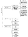
検出部42は、パラメーターを参照して当該テンプレートマッチング処理を行う。すなわち、記憶部44には、各種のパラメーター44aが記憶されており、当該パラメーター44aには、検出部42の検出に関するパラメーターが含まれている。図3は、パラメーター44aの例を示す図である。図3に示す例において、パラメーター44aは、光学パラメーターと動作パラメーターと力制御パラメーターとを含んでいる。
The
光学パラメーターは、検出部42の検出に関するパラメーターである。動作パラメーターと力制御パラメーターとはロボット1〜3を制御する際のパラメーターであり、詳細は後述する。光学パラメーターは、撮像部21に関する撮像部パラメーターと、照明部22に関する照明部パラメーターと、撮像部21によって撮像された対象物の画像に対する画像処理に関する画像処理パラメーターとが含まれる。
The optical parameter is a parameter related to detection by the
図3においては、これらのパラメーターの例が示されている。すなわち、対象物を撮像する際に撮像部21が配置される位置が撮像部の位置として定義され、撮像部パラメーターに含まれている。また、撮像部21は、露光時間と絞りを調整可能な機構を備えており、対象物を撮像する際の露光時間および絞りの値が撮像部パラメーターに含まれている。なお、撮像部の位置は、種々の手法で記述されて良く、例えば、撮像部21のTCPの位置がロボット座標系で記述される構成等を採用可能である。
In FIG. 3, examples of these parameters are shown. That is, the position where the
検出部42は、撮像部パラメーターを参照し、撮像部21の位置を後述する位置制御部43aに受け渡す。この結果、位置制御部43aは、目標位置Ltを生成し、当該目標位置Ltに基づいてロボット1を制御する。また、検出部42は、撮像部パラメーターを参照し、撮像部21の露光時間と絞りを設定する。この結果、撮像部21においては当該露光時間と絞りによって撮像が行われる状態となる。
The
また、対象物を撮像する際に照明部22が配置される位置が照明部の位置として定義され、照明部パラメーターに含まれている。また、照明部22は、明るさを調整可能な機構を備えており、対象物を撮像する際の明るさの値が照明部パラメーターに含まれている。照明部の位置も、種々の手法で記述されて良く、例えば、照明部22のTCPの位置がロボット座標系で記述される構成等を採用可能である。
Moreover, the position where the
検出部42は、照明部パラメーターを参照し、照明部22の位置を後述する位置制御部43aに受け渡す。この結果、位置制御部43aは、目標位置Ltを生成し、当該目標位置Ltに基づいてロボット2を制御する。また、検出部42は、照明部パラメーターを参照し、照明部22の明るさを設定する。この結果、照明部22においては当該明るさの光が出力される状態となる。
The
検出部42は、撮像部21によって撮像された画像に対してテンプレートマッチング処理を適用する際に、画像処理パラメーターを参照する。すなわち、画像処理パラメーターには、テンプレートマッチング処理を実行する際の処理順序を示す画像処理シーケンスが含まれている。また、本実施形態において、テンプレートマッチング処理における閾値が可変であり、現在のテンプレートマッチングの閾値が画像処理パラメーターに含まれている。さらに、検出部42は、テンプレートデータ44cと画像とを比較する前に各種の処理を実行可能である。図3においては、各種の処理として平滑化処理と鮮鋭化処理が例示されており、それぞれの強度が画像処理パラメーターに含まれている。
The
撮像部21から画像が出力されると、検出部42は、画像処理シーケンスに基づいて、画像処理の順序(実行するか否かを含む)を決定し、当該順序で平滑化処理や鮮鋭化処理等の画像処理を実行する。このとき、検出部42は、画像処理パラメーターに記述された強度で平滑化処理や鮮鋭化処理等の画像処理を実行する。また、画像処理シーケンスに含まれる比較(テンプレートデータ44cと画像との比較)を実行する際には、画像処理パラメーターが示す閾値に基づいて比較を行う。
When an image is output from the
なお、以上のように検出部42は、光学パラメーターに基づいて撮像部21や照明部22の位置を特定し、ロボット1、ロボット2を動作させることが可能であるが、ロボット1およびロボット2を駆動する際の位置は、後述する動作パラメーターや力制御パラメーターによって与えられてもよい。
As described above, the
本実施形態において、制御部43は、位置制御部43a、力制御部43b、接触判定部43c、サーボ43dを備えている。また、制御部43においては、モーターM1〜M6の回転角度の組み合わせと、ロボット座標系におけるTCPの位置との対応関係U1が図示しない記憶媒体に記憶され、座標系の対応関係U2が定義され、図示しない記憶媒体に記憶されている。従って、制御部43や後述する算出部41は、対応関係U2に基づいて、任意の座標系におけるベクトルを他の座標系におけるベクトルに変換することができる。例えば、制御部43、算出部41は、力覚センサーPの出力に基づいてセンサー座標系でのロボット1〜3への作用力を取得し、ロボット座標系におけるTCPの位置に作用する力に変換することができる。また、制御部43、算出部41は、力制御座標系で表現された目標力をロボット座標系におけるTCPの位置における目標力に変換することができる。むろん、対応関係U1,U2は記憶部44に記憶されていても良い。
In the present embodiment, the
制御部43は、アームを駆動することによって、ロボット1〜3とともに移動する各種の部位の位置や各種の部位に作用する力を制御することができ、位置の制御は主に位置制御部43a、力の制御は主に力制御部43bによって実行される。サーボ43dは、サーボ制御を実行することが可能であり、エンコーダーE1〜E6の出力が示すモーターM1〜M6の回転角度Daと、制御目標である目標角度Dtとを一致させるフィードバック制御を実行する。すなわち、サーボ43dは、回転角度Daと目標角度Dtとの偏差、当該偏差の積分、当該偏差の微分にサーボゲインKpp,Kpi,Kpdを作用させたPID制御を実行することができる。
The
さらに、サーボ43dは、当該サーボゲインKpp,Kpi,Kpdが作用した出力と、回転角度Daの微分との偏差、当該偏差の積分、当該偏差の微分にサーボゲインKvp,Kvi,Kvdを作用させたPID制御を実行することができる。当該サーボ43dによる制御は、モーターM1〜M6のそれぞれに対して実行可能である。従って、各サーボゲインはロボット1〜3が備える6軸のそれぞれについて実行可能である。なお、本実施形態において、制御部43は、サーボ43dに制御信号を出力し、サーボゲインKpp,Kpi,Kpd,Kvp,Kvi,Kvdを変化させることができる。
Further, the
記憶部44には、上述のパラメーター44aに加え、ロボット1〜3を制御するためのロボットプログラム44bが記憶される。本実施形態において、パラメーター44aおよびロボットプログラム44bは、教示によって生成され、記憶部44に記憶されるが、後述する算出部41によって修正され得る。なお、ロボットプログラム44bは、主に、ロボット1〜3が実施する作業のシーケンス(工程の順序)を示し、予め定義されたコマンドの組み合わせによって記述される。また、パラメーター44aは、主に、各工程を実現するために必要とされる具体的な値であり、各コマンドの引数として記述される。
The
ロボット1〜3を制御するためのパラメーター44aには、上述の光学パラメーターの他に、動作パラメーターと力制御パラメーターが含まれる。動作パラメーターは、ロボット1〜3の動作に関するパラメーターであり、本実施形態においては、位置制御の際に参照されるパラメーターである。すなわち、本実施形態において、一連の作業は複数の工程に分けられ、各工程を実施する際のパラメーター44aが教示によって生成される。動作パラメーターには、当該複数の工程における始点と終点を示すパラメーターが含まれている。当該始点と終点は、種々の座標系で定義されて良く、本実施形態においては制御対象のロボットのTCPの始点および終点がロボット座標系で定義される。すなわち、ロボット座標系の各軸についての並進位置と回転位置とが定義される。
The
また、動作パラメーターには、複数の工程におけるTCPの加減速特性が含まれている。加減速特性は、ロボット1〜3のTCPが各工程の始点から終点まで移動する際の期間と当該期間内の各時刻におけるTCPの速度を示している。図4は、当該加減速特性の例を示す図であり、始点におけるTCPの移動開始時刻t1からTCPが終点に到達する時刻t4までの期間内の各時刻においてTCPの速度Vが定義されている。また、本実施形態において加減速特性には定速期間が含まれる。
Further, the operation parameters include TCP acceleration / deceleration characteristics in a plurality of steps. The acceleration / deceleration characteristics indicate the period when the TCP of the
定速期間は時刻t2〜t3の期間であり、この期間内に置いて速度は一定である。また、この期間の前後においてTCPは加速し、また、減速する。すなわち、時刻t1〜t2までの期間においてTCPは加速し、時刻t3〜t4までの期間においてTCPは減速する。当該加減速特性も種々の座標系で定義されて良く、本実施形態においては制御対象のロボットのTCPについての速度であり、ロボット座標系で定義される。すなわち、ロボット座標系の各軸についての並進速度と回転速度(角速度)とが定義される。 The constant speed period is a period from time t 2 to t 3 , and the speed is constant within this period. In addition, before and after this period, TCP accelerates and decelerates. That, TCP is accelerated during the period from time t 1 ~t 2, TCP is decelerated during the period up to time t 3 ~t 4. The acceleration / deceleration characteristics may also be defined in various coordinate systems. In this embodiment, the acceleration / deceleration characteristics are the speeds of TCP of the robot to be controlled and are defined in the robot coordinate system. That is, the translation speed and rotation speed (angular speed) for each axis of the robot coordinate system are defined.
さらに、動作パラメーターには、サーボゲインKpp,Kpi,Kpd,Kvp,Kvi,Kvdが含まれている。すなわち、制御部43は、動作パラメーターとして記述された値になるようにサーボ43dに制御信号を出力し、サーボゲインKpp,Kpi,Kpd,Kvp,Kvi,Kvdを調整することができる。本実施形態において当該サーボゲインは、上述の工程毎の値であるが、後述の学習等によってより短い期間毎の値とされても良い。
Further, the operation parameters include servo gains Kpp, Kpi, Kpd, Kvp, Kvi, Kvd. That is, the
力制御パラメーターは、ロボット1〜3の力制御に関するパラメーターであり、本実施形態においては、力制御の際に参照されるパラメーターである。始点、終点、加減速特性、サーボゲインは、動作パラメーターと同様のパラメーターであり、始点、終点、加減速特性はロボット座標系の3軸の並進と回転について定義される。また、サーボゲインはモーターM1〜M6のそれぞれについて定義される。ただし、力制御の場合、始点および終点の中の少なくとも一部は定義されない場合(任意とされる場合)もある。例えば、ある方向に作用する力が0になるように衝突回避や倣い制御が行われる場合、当該方向における始点および終点は定義されず、当該方向の力を0にするように位置が任意に変化し得る状態が定義される場合もある。
The force control parameter is a parameter related to the force control of the
また、力制御パラメーターには、力制御座標系を示す情報が含まれている。力制御座標系は、力制御の目標力を定義するための座標系であり、後述の学習が行われる前においては目標力ベクトルの起点が原点であり、目標力ベクトルの方向に1軸が向いている。すなわち、教示において力制御における各種の目標力が定義される際に、各作業の各工程における目標力の作用点が教示される。例えば、対象物の一点を他の物体に当て、両者の接触点で対象物から他の物体に一定の目標力を作用させた状態で対象物の向きを変化させる場合において、対象物が他の物体と接触する点が目標力の作用点となり、当該作用点を原点とした力制御座標系が定義される。そこで、力制御パラメーターにおいては、力制御の目標力が作用する点を原点とし、目標力の方向に1軸が向いている座標系、すなわち、力制御座標系を特定するための情報を、パラメーターに含んでいる。なお、当該パラメーターは種々の定義が可能であるが、例えば、力制御座標系と他の座標系(ロボット座標系等)との関係を示すデータによって定義可能である。 The force control parameter includes information indicating a force control coordinate system. The force control coordinate system is a coordinate system for defining a target force for force control. Before learning described later, the origin of the target force vector is the origin, and one axis is oriented in the direction of the target force vector. ing. That is, when various target forces in force control are defined in teaching, an action point of the target force in each step of each work is taught. For example, when one point of an object is applied to another object and the direction of the object is changed while a certain target force is applied from the object to the other object at the contact point between the two objects, A point in contact with the object becomes an action point of the target force, and a force control coordinate system with the action point as the origin is defined. Therefore, in the force control parameter, information for specifying the coordinate system in which the point where the target force of force control acts is the origin and one axis is oriented in the direction of the target force, that is, the force control coordinate system is Is included. The parameter can be defined in various ways. For example, the parameter can be defined by data indicating the relationship between the force control coordinate system and another coordinate system (robot coordinate system or the like).
さらに、力制御パラメーターには、目標力が含まれている。目標力は、各種の作業において、任意の点に作用すべき力として教示される力であり、力制御座標系において定義される。すなわち、目標力を示す目標力ベクトルが、目標力ベクトルの起点と、起点からの6軸成分(3軸の並進力、3軸のトルク)として定義され、力制御座標系で表現されている。なお、力制御座標系と他の座標系との関係を利用すれば、当該目標力を任意の座標系、例えば、ロボット座標系におけるベクトルに変換することが可能である。 Furthermore, the force control parameter includes a target force. The target force is a force taught as a force to be applied to an arbitrary point in various operations, and is defined in a force control coordinate system. That is, a target force vector indicating the target force is defined as a starting point of the target force vector and a six-axis component (three-axis translational force, three-axis torque) from the starting point, and is expressed in a force control coordinate system. If the relationship between the force control coordinate system and another coordinate system is used, the target force can be converted into a vector in an arbitrary coordinate system, for example, a robot coordinate system.
さらに、力制御パラメーターには、インピーダンスパラメーターが含まれている。すなわち、本実施形態において力制御部43bが実施する力制御は、インピーダンス制御である。インピーダンス制御は、仮想の機械的インピーダンスをモーターM1〜M6によって実現する制御である。この際、TCPが仮想的に有する質量が仮想慣性係数mとして定義され、TCPが仮想的に受ける粘性抵抗が仮想粘性係数dとして定義され、TCPが仮想的に受ける弾性力のバネ定数が仮想弾性係数kとして定義される。インピーダンスパラメーターはこれらのm,d,kであり、ロボット座標系の各軸に対する並進と回転について定義される。本実施形態において当該力制御座標系、目標力、インピーダンスパラメーターは、上述の工程毎の値であるが、後述の学習等によってより短い期間毎の値とされても良い。
Furthermore, the force control parameter includes an impedance parameter. That is, the force control performed by the
本実施形態において、一連の作業は複数の工程に分けられ、各工程を実施するロボットプログラム44bが教示によって生成されるが、位置制御部43aは、ロボットプログラム44bが示す各工程をさらに微小時間ΔT毎の微小工程に細分化する。そして、位置制御部43aは、パラメーター44aに基づいて微小工程毎の目標位置Ltを生成する。力制御部43bは、パラメーター44aに基づいて一連の作業の各工程における目標力fLtを取得する。
In the present embodiment, a series of operations are divided into a plurality of processes, and a
すなわち、位置制御部43aは、動作パラメーターまたは力制御パラメーターが示す始点、終点、加減速特性を参照し、始点から終点まで当該加減速特性で移動する場合(姿勢の場合は姿勢が変化する場合)の微小工程毎のTCPの位置を目標位置Ltとして生成する。力制御部43bは、各工程についての力制御パラメーターが示す目標力を参照し、力制御座標系とロボット座標系との対応関係U2に基づいて当該目標力をロボット座標系における目標力fLtに変換する。当該目標力fLtは、任意の点に作用する力として変換され得るが、ここでは、後述の作用力がTCPに作用している力として表現されるため、当該作用力と目標力fLtとを運動方程式で解析するため、目標力fLtがTCPの位置における力に変換されるとして説明を行う。むろん、工程によっては、目標力fLtが定義されない場合もあり、この場合、力制御を伴わない位置制御が行われる。
That is, the
なお、ここでLの文字は、ロボット座標系を規定する軸の方向(x,y,z,Rx,Ry,Rz)のなかのいずれか1個の方向を表すこととする。また、Lは、L方向の位置も表すこととする。例えば、L=xの場合、ロボット座標系にて設定された目標位置のx方向成分がLt=xtと表記され、目標力のx方向成分がfLt=fxtと表記される。 Here, the letter L represents one of the directions (x, y, z, Rx, Ry, Rz) that define the robot coordinate system. L represents the position in the L direction. For example, when L = x, the x-direction component of the target position set in the robot coordinate system is expressed as Lt = xt, and the x-direction component of the target force is expressed as fLt = fxt.
位置制御や力制御を実行するため、制御部43は、ロボット1〜3の状態を取得することができる。すなわち、制御部43は、モーターM1〜M6の回転角度Daを取得し、対応関係U1に基づいて、当該回転角度Daをロボット座標系におけるTCPの位置L(x,y,z,Rx,Ry,Rz)に変換することができる。また制御部43は、対応関係U2を参照し、TCPの位置Lと、力覚センサーPの検出値および位置とに基づいて、力覚センサーPに現実に作用している力をTCPに作用している作用力fLに変換してロボット座標系において特定することができる。
In order to execute position control and force control, the
すなわち、力覚センサーPに作用している力は、センサー座標系で定義される。そこで、制御部43は、ロボット座標系におけるTCPの位置Lと対応関係U2と力覚センサーPの検出値に基づいて、ロボット座標系においてTCPに作用する作用力fLを特定する。また、ロボットに作用するトルクは、作用力fLと、ツール接触点(エンドエフェクターとワークの接触点)から力覚センサーPまでの距離とから算出することができ、図示されないfLトルク成分として特定される。なお、制御部43は、作用力fLに対して重力補償を行う。重力補償とは、作用力fLから重力成分を除去する処理である。重力補償は、例えば、TCPの姿勢ごとにTCPに作用する作用力fLの重力成分を予め調査しておき、作用力fLから当該重力成分を減算するなどして実現可能である。
That is, the force acting on the force sensor P is defined in the sensor coordinate system. Therefore, the
TCPに作用する重力以外の作用力fLと、TCPに作用すべき目標力fLtとが特定されると、力制御部43bは、対象物等の物体がTCPに存在し、当該TCPに力が作用し得る状態において、インピーダンス制御による補正量ΔL(以後、力由来補正量ΔLと呼ぶ。)を取得する。すなわち、力制御部43bはパラメーター44aを参照して目標力fLtとインピーダンスパラメーターm,d,kを取得し、運動方程式(1)に代入して力由来補正量ΔLを取得する。なお、当該力由来補正量ΔLは、TCPが機械的インピーダンスを受けた場合に、目標力fLtと作用力fLとの力偏差ΔfL(t)を解消するために、TCPが移動すべき位置Lの大きさを意味する。
![]()
![]()
(1)式の左辺は、TCPの位置Lの2階微分値に仮想慣性係数mを乗算した第1項と、TCPの位置Lの微分値に仮想粘性係数dを乗算した第2項と、TCPの位置Lに仮想弾性係数kを乗算した第3項とによって構成される。(1)式の右辺は、目標力fLtから現実の作用力fLを減算した力偏差ΔfL(t)によって構成される。(1)式における微分とは、時間による微分を意味する。 The left side of the equation (1) includes a first term obtained by multiplying the second-order differential value of the TCP position L by the virtual inertia coefficient m, a second term obtained by multiplying the differential value of the TCP position L by the virtual viscosity coefficient d, and And a third term obtained by multiplying the position L of the TCP by the virtual elastic coefficient k. The right side of equation (1) is composed of a force deviation Δf L (t) obtained by subtracting the actual acting force f L from the target force f Lt. The differentiation in the equation (1) means differentiation with time.
力由来補正量ΔLが得られると、制御部43は、対応関係U1に基づいて、ロボット座標系を規定する各軸の方向の動作位置を、各モーターM1〜M6の目標の回転角度である目標角度Dtに変換する。サーボ43dは、目標角度DtからモーターM1〜M6の現実の回転角度であるエンコーダーE1〜E6の出力(回転角度Da)を減算することにより、駆動位置偏差De(=Dt−Da)を算出する。サーボ43dは、パラメーター44aを参照してサーボゲインKpp,Kpi,Kpd,Kvp,Kvi,Kvdを取得し、駆動位置偏差DeにサーボゲインKpp,Kpi,Kpdを乗算した値と、現実の回転角度Daの時間微分値である駆動速度との差である駆動速度偏差に、サーボゲインKvp,Kvi,Kvdを乗算した値とを加算することにより、制御量Dcを導出する。制御量Dcは、モーターM1〜M6のそれぞれについて特定され、各モーターM1〜M6の制御量DcでモーターM1〜M6のそれぞれが制御される。制御部43がモーターM1〜M6を制御する信号は、PWM(Pulse Width Modulation)変調された信号である。
When the force-derived correction amount ΔL is obtained, the
以上のように、運動方程式に基づいて目標力fLtから制御量Dcを導出してモーターM1〜M6を制御するモードを力制御モードというものとする。また制御部43は、エンドエフェクター等の構成要素が対象物Wから力を受けない非接触状態の工程では、力制御を行わず、目標位置から線形演算で導出する回転角度でモーターM1〜M6を制御する。目標位置から線形演算で導出する回転角度でモーターM1〜M6を制御するモードを位置制御モードというものとする。さらに、制御部43は、目標位置から線形演算で導出する回転角度と目標力を運動方程式に代入して導出する回転角度とを例えば線型結合によって統合し、統合した回転角度でモーターM1〜M6を制御するハイブリッドモードでもロボット1を制御することができる。これらのモードはロボットプログラム44bによって予め決められる。
As described above, a mode in which the control amount Dc is derived from the target force fLt based on the equation of motion to control the motors M1 to M6 is referred to as a force control mode. Further, the
位置制御モードまたはハイブリッドモードで制御を行う場合、位置制御部43aは、微小工程毎の目標位置Ltを取得する。微小工程毎の目標位置Ltが得られると、制御部43は、対応関係U1に基づいて、ロボット座標系を規定する各軸の方向の動作位置を、各モーターM1〜M6の目標の回転角度である目標角度Dtに変換する。サーボ43dは、パラメーター44aを参照してサーボゲインKpp,Kpi,Kpd,Kvp,Kvi,Kvdを取得し、目標角度Dtに基づいて、制御量Dcを導出する。制御量Dcは、モーターM1〜M6のそれぞれについて特定され、各モーターM1〜M6の制御量DcでモーターM1〜M6のそれぞれが制御される。この結果、各工程において、TCPは、微小工程毎の目標位置Ltを経由し、加減速特性に従って始点から終点まで移動する。
When the control is performed in the position control mode or the hybrid mode, the
なお、ハイブリッドモードでは、制御部43は、微小工程毎の目標位置Ltに、力由来補正量ΔLを加算することにより動作位置(Lt+ΔL)を特定し、当該動作位置に基づいて目標角度Dtを取得し、制御量Dcを取得する。
In the hybrid mode, the
接触判定部43cは、ロボット1〜3が作業において想定されていない物体と接触したか否かを判定する機能を実行する。本実施形態において、接触判定部43cは、ロボット1〜3のそれぞれが備える力覚センサーPの出力を取得し、出力が予め決められた基準値を超えた場合にロボット1〜3が作業において想定されていない物体と接触したと判定する。この場合において、種々の処理が行われて良いが、本実施形態において接触判定部43cは、ロボット1〜3の制御量Dcを0としてロボット1〜3を停止させる。なお、停止させる際の制御量は、種々の制御量であって良く、直前の制御量Dcをキャンセルする制御量でロボット1〜3を動作させる構成等であっても良い。
The
(3)ピックアップ処理:
次に、以上の構成におけるロボット1〜3の動作を説明する。ここでは、ロボット2の照明部22で照明され、ロボット1の撮像部21で撮像された対象物Wをロボット3のグリッパー23でピックアップする作業を例にして説明する。むろん、ロボット1〜3による作業は、ピックアップ作業に限定されず、他にも種々の作業(例えば、ネジ締め作業、挿入作業、ドリルによる穴あけ作業、バリ取り作業、研磨作業、組み立て作業、製品チェック作業等)に適用可能である。ピックアップ処理は、上述のコマンドによって記述されたロボット制御プログラムによって検出部42および制御部43が実行する処理によって実現される。本実施形態においてピックアップ処理は、作業台に対象物Wが配置した状態で実行される。
(3) Pickup processing:
Next, the operation of the
図5は、ピックアップ処理のフローチャートの例を示す図である。ピックアップ処理が開始されると、検出部42は、撮像部21が撮像した画像を取得する(ステップS100)。すなわち、検出部42は、パラメーター44aを参照して照明部22の位置を特定し、当該位置を位置制御部43aに対して受け渡す。この結果、位置制御部43aは、現在の照明部22の位置を始点、パラメーター44aが示す照明部22の位置を終点とした位置制御を実行し、パラメーター44aが示す照明部の位置に照明部22を移動させる。次に、検出部42はパラメーター44aを参照して照明部22の明るさを特定し、照明部22を制御して照明の明るさを当該明るさに設定する。
FIG. 5 is a diagram illustrating an example of a flowchart of the pickup process. When the pickup process is started, the
さらに、検出部42は、パラメーター44aを参照して撮像部21の位置を特定し、当該位置を位置制御部43aに対して受け渡す。この結果、位置制御部43aは、現在の撮像部21の位置を始点、パラメーター44aが示す撮像部21の位置を終点とした位置制御を実行し、パラメーター44aが示す照明部の位置に撮像部21を移動させる。次に、検出部42はパラメーター44aを参照して撮像部21の露光時間および絞りを特定し、撮像部21を制御して露光時間および絞りを当該露光時間および絞りに設定する。露光時間および絞りの設定が完了すると、撮像部21は、画像を撮像し、検出部42に対して出力する。検出部42は、当該画像を取得する。
Furthermore, the
次に、検出部42は、画像に基づいて、対象物の検出が成功したか否かを判定する(ステップS105)。すなわち、検出部42は、パラメーター44aを参照して画像処理シーケンスを特定し、当該画像処理シーケンスが示す各処理をパラメーター44aが示す強度で実行する。また、検出部42は、テンプレートデータ44cを参照し、テンプレートデータ44cと画像との差分を閾値と比較し、差分が閾値以下である場合に、対象物の検出が成功したと判定する。
Next, the
ステップS105において、対象物の検出が成功したと判定されない場合、検出部42は、テンプレートデータ44cと画像の相対位置、またはテンプレートデータ44cの大きさ、の少なくとも一方を変化させ、ステップS100以降の処理を繰り返す。一方、ステップS105において、対象物の検出が成功したと判定された場合、制御部43は、制御目標を特定する(ステップS110)。
If it is not determined in step S105 that the detection of the object has succeeded, the
本例におけるピックアップ処理は、検出部42が検出した対象物Wの位置姿勢に合わせてロボット3のグリッパー23を移動させ、姿勢を変化させ、グリッパー23で対象物Wをピックアップし、所定の位置まで対象物Wを運んでグリッパー23から対象物Wを離す作業である。そこで、位置制御部43aおよび力制御部43bは、ロボットプログラム44bに基づいて一連の作業を構成する複数の工程を特定する。
In the pick-up process in this example, the
制御目標の特定対象となる工程は、各工程の中で未処理かつ時系列で先に存在する工程である。制御目標の特定対象となる工程が力制御モードの工程である場合、力制御部43bは、パラメーター44aの力制御パラメーターを参照し、力制御座標系、目標力を取得する。力制御部43bは、力制御座標系に基づいて、当該目標力をロボット座標系の目標力fLtに変換する。また、力制御部43bは、力覚センサーPの出力をTCPに作用している作用力fLに変換する。さらに、力制御部43bは、パラメーター44aの力制御パラメーターを参照し、インピーダンスパラメーターm,d,kに基づいて、力由来補正量ΔLを制御目標として取得する。
The process to be specified as the control target is a process that is unprocessed and exists in time series in each process. When the process that is the target for specifying the control target is a process in the force control mode, the
制御目標の特定対象となる工程が位置制御モードである場合、位置制御部43aは、当該工程を微小工程に細分化する。そして、位置制御部43aは、パラメーター44aの動作パラメーターを参照し、始点、終点、および加減速特性に基づいて、微小工程毎の目標位置Ltを制御目標として取得する。制御目標の特定対象となる工程がハイブリッドモードである場合、位置制御部43aは、当該工程を微小工程に細分化し、パラメーター44aの力制御パラメーターを参照し、始点、終点、および加減速特性に基づいて、微小工程毎の目標位置Ltを取得し、力制御座標系、目標力fLt、インピーダンスパラメーター、作用力fLに基づいて力由来補正量ΔLを取得する。これらの目標位置Ltおよび力由来補正量ΔLが制御目標である。
When the process targeted for specifying the control target is the position control mode, the
制御目標が特定されると、サーボ43dは、現在の制御目標でロボット3を制御する(ステップS115)。すなわち、現在の工程が力制御モードまたはハイブリッドモードの工程である場合、サーボ43dは、パラメーター44aの力制御パラメーターを参照し、サーボゲインに基づいて、制御目標に対応する制御量Dcを特定し、モーターM1〜M6のそれぞれを制御する。現在の工程が位置制御モードの工程である場合、サーボ43dは、パラメーター44aの動作パラメーターを参照し、サーボゲインに基づいて、制御目標に対応する制御量Dcを特定し、モーターM1〜M6のそれぞれを制御する。
When the control target is specified, the
次に、制御部43は、現在の工程が終了したか否かを判定する(ステップS120)。当該判定は、種々の終了判定条件によって実行されてよく、位置制御であれば、例えば、TCPが目標位置に達したことや目標位置においてTCPが整定したこと等が挙げられる。力制御であれば、例えば、作用力が目標力に一致した状態から作用力が指定の大きさ以上、または指定の大きさ以下に変化したことや、TCPが指定の範囲外になったこと等が挙げられる。前者は、例えば、ピックアップ作業における対象物の把持動作の完了や、把持解除動作の完了等が挙げられる。後者は、例えば、ドリルによる対象物の貫通作業においてドリルが貫通した場合等が挙げられる。
Next, the
むろん、他にも各工程が失敗したと推定される場合において、工程が終了したと判定されて良い。ただし、この場合には、作業の中止や中断が行われることが好ましい。工程の失敗を判定するための終了判定条件としては、例えば、TCPの移動速度や加速度が上限値を超えた場合やタイムアウトが発生した場合等が挙げられる。終了判定条件を充足したか否かは、各種のセンサー、力覚センサーPや撮像部21、他のセンサー等が利用されて良い。
Of course, when it is estimated that each process has failed, it may be determined that the process has been completed. However, in this case, it is preferable that the work is stopped or interrupted. As an end determination condition for determining a process failure, for example, a case where a TCP moving speed or acceleration exceeds an upper limit value or a time-out occurs can be cited. Various sensors, force sensor P, imaging
ステップS120において、現在の工程が終了したと判定されない場合、制御部43は、微小時間ΔT後に、次の微小工程についてステップS115以降の処理を実行する。すなわち、現在の工程が位置制御モードまたはハイブリッドモードである場合、位置制御部43aは、次の微小工程における目標位置Ltを制御目標としてロボット3を制御する。また、現在の工程が力制御モードまたはハイブリッドモードである場合、力制御部43bは、再度力覚センサーPの出力に基づいて作用力fLを取得し、最新の作用力fLに基づいて特定される力由来補正量ΔLを制御目標としてロボット3を制御する。
In step S120, when it is not determined that the current process is completed, the
ステップS120において、現在の工程が終了したと判定された場合、制御部43は、作業が終了したか否かを判定する(ステップS125)。すなわち、ステップS120で終了したと判定された工程が最終工程であった場合、制御部43は、作業が終了したと判定する。ステップS125で作業が終了したと判定されなかった場合、制御部43は、作業シーケンスの次の工程を現在の工程に変更し(ステップS130)、ステップS110以降の処理を実行する。ステップS125で作業が終了したと判定された場合、制御部43は、作業が終了したと判定し、ピックアップ処理を終了する。
When it is determined in step S120 that the current process is completed, the
(4)学習処理:
本実施形態にかかる制御装置40は、以上のように、パラメーター44aに基づいてロボット1〜3を制御することができる。上述の実施形態において、パラメーター44aは教示によって生成されたが、人為的な教示によってパラメーター44aを最適化することは困難である。
(4) Learning process:
As described above, the
例えば、検出部42による対象物Wの検出において、同じ対象物Wであっても、光学パラメーターが異なれば対象物Wの位置、画像内での対象物の像や位置、対象物Wに生じる影など、様々な要素が変化し得る。従って、光学パラメーターを変化させると、検出部42による対象物Wの検出精度が変化し得る。そして、光学パラメーターを変化させた場合に対象物Wの検出精度がどのように変化するのかは、必ずしも明らかではない。
For example, in the detection of the object W by the
また、動作パラメーターや力制御パラメーターはロボット1〜3の制御に利用されるが、ロボット1〜3のように複数の自由度(可動軸)を有するロボットは極めて多数のパターンで動作することが可能である。そして、ロボット1〜3においては、振動や異音、オーバーシュート等の好ましくない動作が発生しないようにパターンが決められている必要がある。さらに、エンドエフェクターとして各種の装置が取り付けられる場合、ロボット1〜3の重心が変化し得るため、最適な動作パラメーター、力制御パラメーターも変化し得る。そして、動作パラメーターや力制御パラメーターを変化させた場合に、ロボット1〜3の動作がどのように変化するのかは、必ずしも明らかではない。
The operation parameters and force control parameters are used to control the
さらに、力制御パラメーターは、ロボット1〜3において力制御が行われる場合に利用されるが、ロボット1〜3において実施される各作業において、力制御パラメーターを変化させた場合に、ロボット1〜3の動作がどのように変化するのかは、必ずしも明らかではない。例えば、どのような方向においてどのようなインピーダンスパラメーターが最適であるのか、全ての作業工程において推定することは困難である。このため、検出部42の検出精度を高めたり、ロボット1〜3の潜在的な性能を引き出したりするためには極めて多数の試行錯誤を行う必要がある。
Further, the force control parameter is used when the force control is performed in the
しかし、人為的に極めて多数の試行錯誤を行うことは困難であるため、対象物Wの検出精度が充分に高く、当該検出精度がほぼ上限に達していると推定される状態や、ロボット1〜3の潜在的な性能が引き出されている状態(所要時間や消費電力等のパフォーマンスのさらなる向上が困難な状態)を人為的に実現することは困難である。また、パラメーター44aの調整を行うためには、パラメーター44aの変化による検出精度の変化やロボット1〜3の動作の変化を熟知しているオペレーターが必要になり、熟知していないオペレーターがパラメーター44aの調整を行うことは困難である。また、常に熟練のオペレーターを必要とするシステムはとても不便である。
However, since it is difficult to artificially perform a large number of trials and errors, the detection accuracy of the object W is sufficiently high and the detection accuracy is estimated to have almost reached the upper limit. It is difficult to artificially realize a state in which the potential performance of 3 is drawn (a state where it is difficult to further improve performance such as required time and power consumption). Further, in order to adjust the
そこで、本実施形態においては、人為的なパラメーター44aの決定作業を行うことなく、自動的にパラメーター44aを決定するための構成を備えている。なお、本実施形態によれば、多少のパラメーター44aの変更によって検出精度がより向上しないと推定される(検出精度が極大であると推定される)状態や、多少のパラメーター44aの変更によってロボット1〜3の性能が高性能化することはないと推定される(性能が極大であると推定される)状態を実現することができる。本実施形態においては、これらの状態を最適化された状態と呼ぶ。
Therefore, in the present embodiment, there is provided a configuration for automatically determining the
本実施形態において制御装置40は、パラメーター44aの自動的な決定のために算出部41を備えている。本実施形態において、算出部41は、機械学習を用いて、光学パラメーターと動作パラメーターと力制御パラメーターとを算出することができる。図6は、算出部41の構成を示す図であり、図2に示す構成の一部を省略し、算出部41の詳細を示した図である。なお、図6に示す記憶部44は、図2に示す記憶部44と同一の記憶媒体であり、各図においては記憶された情報の一部の図示が省略されている。
In the present embodiment, the
算出部41は、状態変数を観測する状態観測部41aと、観測された状態変数に基づいてパラメーター44aを学習する学習部41bとを備えている。本実施形態において、状態観測部41aは、パラメーター44aを変化させたことによって生じた結果を状態変数として観測する。このため、状態観測部41aは、サーボ43dの制御結果と、エンコーダーE1〜E6の値と、力覚センサーPの出力と、検出部42が取得する画像とを状態変数として取得可能である。
The
具体的には、状態観測部41aは、サーボ43dの制御結果として、モーターM1〜M6に供給される電流値を観測する。当該電流値は、モーターM1〜M6で出力されるトルクに相当する。エンコーダーE1〜E6の出力は、対応関係U1に基づいてロボット座標系におけるTCPの位置に変換される。従って、状態観測部41aは、ロボット1であれば撮像部21の位置、ロボット2であれば照明部22の位置、ロボット3であればグリッパー23の位置を観測することができる。
Specifically, the
力覚センサーPの出力は、対応関係U2に基づいてロボット座標系におけるTCPに作用する作用力に変換される。従って、状態観測部41aは、ロボット1〜3への作用力を状態変数として観測することができる。検出部42が取得する画像は、撮像部21で撮像された画像であり、状態観測部41aは、当該画像を状態変数として観測することができる。状態観測部41aは、学習対象のパラメーター44aに応じて観測対象の状態変数を適宜選択することができる。
The output of the force sensor P is converted into an acting force acting on the TCP in the robot coordinate system based on the correspondence U2. Accordingly, the
学習部41bは、学習によってパラメーター44aを最適化することができればよく、本実施形態においては、強化学習によってパラメーター44aを最適化する。具体的には、学習部41bは、状態変数に基づいてパラメーター44aを変化させる行動を決定し、当該行動を実行する。当該行動後の状態に応じて報酬を評価すれば、当該行動の行動価値が判明する。そこで、算出部41は、状態変数の観測と、当該状態変数に応じた行動の決定と、当該行動によって得られる報酬の評価とを繰り返すことによって、パラメーター44aを最適化する。
The learning unit 41b only needs to be able to optimize the
本実施形態において、算出部41は、パラメーター44aの中から学習対象のパラメーターを選択して学習を行うことができる。本実施形態においては、光学パラメーターの学習と、動作パラメーターの学習と、力制御パラメーターの学習とのそれぞれを独立して実行することができる。
In the present embodiment, the
(4−1)光学パラメーターの学習:
図7はエージェントと環境とからなる強化学習のモデルに沿って光学パラメーターの学習例を説明する図である。図7に示すエージェントは、予め決められた方策に応じて行動aを選択する機能に相当し、学習部41bによって実現される。環境は、エージェントが選択した行動aと現在の状態sとに基づいて次の状態s'を決定し、行動aと状態sと状態s'とに基づいて即時報酬rを決定する機能に相当し、状態観測部41aおよび学習部41bによって実現される。
(4-1) Learning optical parameters:
FIG. 7 is a diagram for explaining an optical parameter learning example along a reinforcement learning model including an agent and an environment. The agent shown in FIG. 7 corresponds to a function of selecting the action a according to a predetermined policy, and is realized by the learning unit 41b. The environment corresponds to the function of determining the next state s ′ based on the action a selected by the agent and the current state s, and determining the immediate reward r based on the action a, the state s, and the state s ′. This is realized by the
本実施形態においては、予め決められた方策によって学習部41bが行動aを選択し、状態観測部41aが状態の更新を行う処理を繰り返すことにより、ある状態sにおけるある行動aの行動価値関数Q(s,a)を算出するQ学習が採用される。すなわち、本例においては、下記の式(2)によって行動価値関数を更新する。そして、行動価値関数Q(s,a)が適正に収束した場合には、当該行動価値関数Q(s,a)を最大化する行動aが最適な行動であると見なされ、当該行動aを示すパラメーター44aが最適化されたパラメーターであると見なされる。
![]()
![]()
ここで、行動価値関数Q(s,a)は、状態sにおいて行動aを取った場合において将来にわたって得られる収益(本例では割引報酬総和)の期待値である。報酬はrであり、状態s、行動a、報酬rの添え字tは、時系列で繰り返す試行過程における1回分のステップを示す番号(試行番号と呼ぶ)であり、行動決定後に状態が変化すると試行番号がインクリメントされる。従って、式(2)内の報酬rt+1は状態stで行動atが選択され、状態がst+1になった場合に得られる報酬である。αは学習率、γは割引率である。また、a'は、状態st+1で取り得る行動at+1の中で行動価値関数Q(st+1,at+1)を最大化する行動であり、maxa'Q(st+1,a')は、行動a'が選択されたことによって最大化された行動価値関数である。 Here, the action value function Q (s, a) is an expected value of profit (in this example, the sum of discount rewards) obtained in the future when the action a is taken in the state s. The reward is r, and the subscript t of the state s, the action a, and the reward r is a number (referred to as a trial number) indicating one step in the trial process repeated in time series, and the state changes after the action is determined. The trial number is incremented. Thus, reward r t + 1 in equation (2) Behavioral a t in state s t is selected, a reward condition is obtained when it becomes s t + 1. α is a learning rate and γ is a discount rate. Further, a ′ is an action that maximizes the action value function Q (s t + 1 , a t + 1 ) among actions a t + 1 that can be taken in the state s t + 1 , and max a ′ Q ( s t + 1 , a ′) is an action value function maximized by selecting the action a ′.
光学パラメーターの学習においては、光学パラメーターを変化させることが行動の決定に相当しており、学習対象のパラメーターと取り得る行動とを示す行動情報44dが記憶部44に予め記録される。すなわち、当該行動情報44dに学習対象として記述された光学パラメーターが学習対象となる。図7においては、光学パラメーターの中の撮像部パラメーターと、照明部パラメーターと、画像処理パラメーターとの一部が学習対象となっている例を示している。
In learning of optical parameters, changing the optical parameters corresponds to determination of behavior, and behavior information 44 d indicating parameters to be learned and possible behavior is recorded in the
具体的には、撮像部パラメーターの中で撮像部21のx座標、y座標が学習対象となっている。従って、この例においてz座標やxyz軸に対する回転(姿勢)は学習対象となっておらず、撮像部21は、対象物Wが置かれる作業台に向いている状態であるとともに、撮像部21のx−y平面内での移動が学習対象である。むろん、他の撮像部パラメーター、例えば、撮像部21の姿勢やz座標、露光時間や絞りが学習対象であっても良い。
Specifically, among the imaging unit parameters, the x coordinate and y coordinate of the
また、図7に示す例においては、照明部パラメーターの中で、照明部22のx座標、y座標および照明部の明るさが学習対象となっている。従って、この例においてz座標やxyz軸に対する回転(姿勢)は学習対象となっておらず、照明部22は、対象物Wが置かれる作業台に向いている状態であるとともに、照明部22のx−y平面内での移動が学習対象である。むろん、他の照明部パラメーター、例えば、照明部22の姿勢やz座標が学習対象であっても良い。
In the example shown in FIG. 7, among the illumination unit parameters, the x coordinate and y coordinate of the
さらに、図7に示す例においては、画像処理パラメーターの中で、平滑化処理の強度と鮮鋭化処理の強度とテンプレートマッチングの閾値が学習対象となっている。従って、この例において、画像処理シーケンスは学習対象となっておらず、撮像部21で撮像された画像に対する画像処理の順序は変化しない(むろん、画像処理シーケンスが学習対象である実施形態も採用可能である)。
Further, in the example shown in FIG. 7, the smoothing processing strength, the sharpening processing strength, and the template matching threshold are learning targets in the image processing parameters. Therefore, in this example, the image processing sequence is not a learning target, and the order of image processing for the image captured by the
図7に示す例において行動には値を一定値増加させる行動と、値を一定値減少させる行動とが存在する。従って、図7に示す全8個のパラメーターにおいて取り得る行動は全16個である(行動a1〜行動a16)。行動情報44dは、学習対象のパラメーターと取り得る行動とを示しているため、図7に示す例であれば、図示した8個のパラメーターが行動情報44dに学習対象として記述される。また、各行動を特定するための情報(行動のID、各行動での増減量等)が行動情報44dに記述される。 In the example illustrated in FIG. 7, there are actions that increase the value by a certain value and actions that decrease the value by a certain value. Therefore, there are 16 actions that can be taken in all 8 parameters shown in FIG. 7 (action a1 to action a16). Since the action information 44d indicates the parameters to be learned and the actions that can be taken, in the example shown in FIG. 7, the illustrated eight parameters are described as learning objects in the action information 44d. Also, information for identifying each action (action ID, increase / decrease amount in each action, etc.) is described in the action information 44d.
図7に示す例において、報酬は対象物Wの検出の成否に基づいて特定される。すなわち、学習部41bは、行動aとして光学パラメーターを変化させた後、当該光学パラメーターによってロボット1,2を動作させ、検出部42によって撮像部21が撮像した画像を取得する。そして、学習部41bは、当該光学パラメーターに基づいてテンプレートマッチング処理を実行し、対象物Wの検出が成功したか否かを判定する。さらに、学習部41bは、検出の成否によって行動a、状態s、s'の報酬を決定する。当該報酬は、対象物Wの検出の成否に基づいて決定されれば良く、例えば、検出の成功に正(例えば+1)、検出の失敗に負(例えば−1)の報酬を与える構成等を採用可能である。この構成によれば、対象物の検出精度を高めるように最適化を行うことができる。
In the example shown in FIG. 7, the reward is specified based on the success or failure of detection of the object W. That is, the learning unit 41b changes the optical parameter as the action a, then operates the
現在の状態sにおいて行動aが採用された場合における次の状態s'は、行動aとしてのパラメーターの変化が行われた後にロボット1,2を動作させ、状態観測部41aが状態を観測することによって特定可能である。なお、本例にかかる光学パラメーターの学習においてロボット3は動作しない。図7に示す例において、状態変数には、撮像部21のx座標、y座標と、照明部22のx座用、y座標、照明部22の明るさと、平滑化処理の強度、鮮鋭化処理の強度、テンプレートマッチングの閾値と、撮像部21で撮像された画像とが含まれている。
The next state s ′ when the action a is adopted in the current state s is that the
従って、この例において、状態観測部41aは、行動aが実行された後に、ロボット1のエンコーダーE1〜E6の出力をU1に基づいて変換して撮像部21のx座標およびy座標を観測する。また、状態観測部41aは、行動aが実行された後に、ロボット2のエンコーダーE1〜E6の出力をU1に基づいて変換して照明部22のx座標およびy座標を観測する。
Therefore, in this example, after the action a is executed, the
本実施形態において、照明部22の明るさは、パラメーター44aによって誤差無く調整可能であると見なされており(または誤差が影響ないと見なされており)、状態観測部41aは、パラメーター44aに含まれる照明部の明るさを取得して状態変数が観測されたと見なす。むろん、照明部22の明るさは、センサー等によって実測されても良いし、撮像部21が撮像した画像に基づいて(例えば、平均階調値等により)観測されても良い。状態観測部41aは、平滑化処理の強度、鮮鋭化処理の強度、テンプレートマッチングの閾値についても、パラメーター44aを参照して現在の値を取得し、状態変数が観測されたと見なす。
In the present embodiment, it is assumed that the brightness of the
さらに、状態観測部41aにおいては、撮像部21が撮像し、検出部42が取得した画像を状態変数として取得する(図7に示す太枠)。すなわち、状態観測部41aは、撮像部21が撮像した画像(対象物が存在し得る注目領域等の画像であっても良い)の画素毎の階調値を状態変数として観測する。撮像部のx座標等は、行動であるとともに観測対象としての状態であるが、撮像部21が撮像した画像は行動ではない。従って、この意味で、撮像された画像は、光学パラメーターの変化から直接的に推定することが困難な変化をし得る状態変数である。また、検出部42は、当該画像に基づいて対象物を検出するため、当該画像は検出の成否に直接的に影響を与え得る状態変数である。従って、状態変数として、当該画像を観測することにより、人為的に改善することが困難なパラメーターの改善を行い、効果的に検出部42の検出精度を高めるように光学パラメーターを最適化することが可能になる。
Further, in the
(4−2)光学パラメーターの学習例:
次に、光学パラメーターの学習例を説明する。学習の過程で参照される変数や関数を示す情報は、学習情報44eとして記憶部44に記憶される。すなわち、算出部41は、状態変数の観測と、当該状態変数に応じた行動の決定と、当該行動によって得られる報酬の評価とを繰り返すことによって行動価値関数Q(s,a)を収束させる構成が採用されている。そこで、本例において、学習の過程で状態変数と行動と報酬との時系列の値が、順次、学習情報44eに記録されていく。
(4-2) Optical parameter learning example:
Next, an example of learning optical parameters will be described. Information indicating variables and functions referred to in the learning process is stored in the
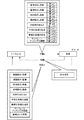
行動価値関数Q(s,a)は、種々の手法で算出されて良く、多数回の試行に基づいて算出されても良いが、本実施形態においては、行動価値関数Q(s,a)を近似的に算出する一手法であるDQN(Deep Q−Network)が採用されている。DQNにおいては、多層ニューラルネットワークを用いて行動価値関数Q(s,a)を推定する。本例においては、状態sを入力とし、選択し得る行動の数N個の行動価値関数Q(s,a)の値を出力とする多層ニューラルネットワークが採用されている。 The action value function Q (s, a) may be calculated by various methods, and may be calculated based on a number of trials. In the present embodiment, the action value function Q (s, a) is calculated. DQN (Deep Q-Network), which is a method of calculating approximately, is employed. In DQN, an action value function Q (s, a) is estimated using a multilayer neural network. In this example, a multi-layer neural network that employs the state s as an input and outputs the values of N action value functions Q (s, a) that can be selected is employed.
図8は、本例において採用されている多層ニューラルネットワークを模式的に示す図である。図8において、多層ニューラルネットワークは、M個(Mは2以上の整数)の状態変数を入力とし、N個(Nは2以上の整数)個の行動価値関数Qの値を出力としている。例えば、図7に示す例であれば、撮像部のx座標〜テンプレートマッチングの閾値までの8個の状態変数と撮像された画像の画素数との和がM個であり、M個の状態変数の値が多層ニューラルネットワークに入力される。図8においては、試行番号tにおけるM個の状態をs1t〜sMtとして示している。 FIG. 8 is a diagram schematically showing a multilayer neural network employed in this example. In FIG. 8, the multilayer neural network receives M (M is an integer of 2 or more) state variables as inputs and outputs N (N is an integer of 2 or more) action value functions Q as outputs. For example, in the example illustrated in FIG. 7, the sum of the eight state variables from the x coordinate of the imaging unit to the threshold value for template matching and the number of pixels of the captured image is M, and the M state variables Is input to the multilayer neural network. In FIG. 8, M states at trial number t are shown as s 1t to s Mt.
N個は選択し得る行動aの数であり、多層ニューラルネットワークの出力は、入力された状態sにおいて特定の行動aが選択された場合の行動価値関数Qの値である。図8においては、試行番号tにおいて選択し得る行動a1t〜aNtのそれぞれにおける行動価値関数QをQ(st,a1t)〜Q(st,aNt)として示している。当該Qに含まれるstは入力された状態s1t〜sMtを代表して示す文字である。図7に示す例であれば、16個の行動が選択可能であるためN=16である。むろん、行動aの内容や数(Nの値)、状態sの内容や数(Mの値)は試行番号tに応じて変化しても良い。 N is the number of actions a that can be selected, and the output of the multilayer neural network is the value of the action value function Q when a specific action a is selected in the input state s. In FIG. 8, the action value functions Q in the actions a 1t to a Nt that can be selected at the trial number t are shown as Q (s t , a 1t ) to Q (s t , a Nt ). S t included in the Q is a character showing on behalf of the state s 1t ~s Mt entered. In the example shown in FIG. 7, since 16 actions can be selected, N = 16. Of course, the contents and number of actions a (value of N) and the contents and number of states s (value of M) may be changed according to the trial number t.
図8に示す多層ニューラルネットワークは、各層の各ノードにおいて直前の層の入力(1層目においては状態s)に対する重みwの乗算とバイアスbの加算とを実行し、必要に応じて活性化関数を経た出力を得る(次の層の入力になる)演算を実行するモデルである。本例においては、層DLがP個(Pは1以上の整数)存在し、各層において複数のノードが存在する。 The multilayer neural network shown in FIG. 8 performs multiplication of the weight w and addition of the bias b to the input of the immediately preceding layer (state s in the first layer) at each node of each layer, and activates the function as necessary. Is a model that executes an operation to obtain an output that has passed through (becomes the input of the next layer). In this example, there are P layers DL (P is an integer of 1 or more), and there are a plurality of nodes in each layer.
図8に示す多層ニューラルネットワークは各層における重み、とバイアスb、活性化関数、層の順序等によって特定される。そこで、本実施形態においては、当該多層ニューラルネットワークを特定するためのパラメーター(入力から出力を得るために必要な情報)が学習情報44eとして記憶部44に記録される。なお、学習の際には、多層ニューラルネットワークを特定するためのパラメーターの中で可変の値(例えば,重みwとバイアスb)を更新していくことになる。ここでは、学習の過程で変化し得る多層ニューラルネットワークのパラメーターをθと表記する。当該θを使用すると、上述の行動価値関数Q(st,a1t)〜Q(st,aNt)は、Q(st,a1t;θt)〜Q(st,aNt;θt)とも表記できる。
The multilayer neural network shown in FIG. 8 is specified by weights in each layer, bias b, activation function, layer order, and the like. Therefore, in the present embodiment, parameters for identifying the multilayer neural network (information necessary for obtaining output from input) are recorded in the
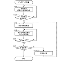
次に、図9に示すフローチャートに沿って学習処理の手順を説明する。光学パラメーターの学習処理は、ロボット1,2の運用過程において実施されても良いし、実運用の前に事前に学習処理が実行されてもよい。ここでは、実運用の前に事前に学習処理が実行される構成(多層ニューラルネットワークを示すθが最適化されると、その情報が保存され、次回以降の運用で利用される構成)に従って学習処理を説明する。
Next, the procedure of the learning process will be described along the flowchart shown in FIG. The optical parameter learning process may be performed in the operation process of the
学習処理が開始されると、算出部41は、学習情報44eを初期化する(ステップS200)。すなわち、算出部41は、学習を開始する際に参照されるθの初期値を特定する。初期値は、種々の手法によって決められて良く、過去に学習が行われていない場合においては、任意の値やランダム値等がθの初期値となっても良いし、ロボット1,2や撮像部21,照明部22の光学特性を模擬するシミュレーション環境を準備し、当該環境に基づいて学習または推定したθを初期値としてもよい。
When the learning process is started, the
過去に学習が行われた場合は、当該学習済のθが初期値として採用される。また、過去に類似の対象についての学習が行われた場合は、当該学習におけるθが初期値とされても良い。過去の学習は、ロボット1,2を用いてユーザーが行ってもよいし、ロボット1,2の製造者がロボット1,2の販売前に行ってもよい。この場合、製造者は、対象物や作業の種類に応じて複数の初期値のセットを用意しておき、ユーザーが学習する際に初期値を選択する構成であっても良い。θの初期値が決定されると、当該初期値が現在のθの値として学習情報44eに記憶される。
When learning has been performed in the past, the learned θ is adopted as an initial value. Further, when learning is performed on a similar target in the past, θ in the learning may be set as an initial value. The past learning may be performed by the user using the
次に、算出部41は、パラメーターを初期化する(ステップS205)。ここでは、光学パラメーターが学習対象であるため、算出部41は、光学パラメーターを初期化する。すなわち、算出部41は、ロボット1のエンコーダーE1〜E6の出力を対応関係U1で変換し、撮像部21の位置を初期値として設定する。また、算出部41は、予め決められた初期の露光時間(過去に学習が行われた場合には最新の露光時間)を撮像部21の露光時間の初期値として設定する。さらに、算出部41は、撮像部21に制御信号を出力し、現在の絞りの値を初期値として設定する。
Next, the
さらに、算出部41は、ロボット2のエンコーダーE1〜E6の出力を対応関係U1で変換し、照明部22の位置を初期値として設定する。また、算出部41は、予め決められた初期の明るさ(過去に学習が行われた場合には最新の明るさ)を照明部22の明るさの初期値として設定する。さらに、算出部41は、平滑化処理の強度、鮮鋭化処理の強度、テンプレートマッチングの閾値、画像処理シーケンスについて予め決められた初期値(過去に学習が行われた場合には最新の値)を設定する。初期化されたパラメーターは記憶部44に現在のパラメーター44aとして記憶される。
Furthermore, the
次に、状態観測部41aは、状態変数を観測する(ステップS210)。すなわち、制御部43は、パラメーター44aおよびロボットプログラム44bを参照してロボット1,2を制御する。検出部42は、制御後の状態で撮像部21が撮像した画像に基づいて対象物Wの検出処理(上述のステップS100,S105に相当)を実行する。この後、状態観測部41aは、ロボット1のエンコーダーE1〜E6の出力をU1に基づいて変換して撮像部21のx座標およびy座標を観測する。また、状態観測部41aは、ロボット2のエンコーダーE1〜E6の出力をU1に基づいて変換して照明部22のx座標およびy座標を観測する。さらに、状態観測部41aは、パラメーター44aを参照して照明部22に設定されるべき明るさを取得して状態変数が観測されたと見なす。
Next, the
さらに、状態観測部41aは、平滑化処理の強度、鮮鋭化処理の強度、テンプレートマッチングの閾値についても、パラメーター44aを参照して現在の値を取得し、状態変数が観測されたと見なす。さらに、状態観測部41aにおいては、撮像部21が撮像し、検出部42が取得した画像を取得し、各画素の階調値を状態変数として取得する。
Furthermore, the
次に、学習部41bは、行動価値を算出する(ステップS215)。すなわち、学習部41bは、学習情報44eを参照してθを取得し、学習情報44eが示す多層ニューラルネットワークに最新の状態変数を入力し、N個の行動価値関数Q(st,a1t;θt)〜Q(st,aNt;θt)を算出する。
Next, the learning unit 41b calculates an action value (step S215). That is, the learning unit 41b obtains θ by referring to the learning
なお、最新の状態変数は、初回の実行時においてステップS210、2回目以降の実行時においてステップS225の観測結果である。また、試行番号tは初回の実行時において0、2回目以降の実行時において1以上の値となる。学習処理が過去に実施されていない場合、学習情報44eが示すθは最適化されていないため、行動価値関数Qの値としては不正確な値となり得るが、ステップS215以後の処理の繰り返しにより、行動価値関数Qは徐々に最適化していく。また、ステップS215以後の処理の繰り返しにおいて、状態s、行動a、報酬rは、各試行番号tに対応づけられて記憶部44に記憶され、任意のタイミングで参照可能である。
Note that the latest state variable is the observation result of step S210 at the first execution time and the observation result at step S225 at the second and subsequent execution time. The trial number t is 0 at the first execution, and is 1 or more at the second and subsequent executions. If the learning process has not been performed in the past, θ indicated by the learning
次に、学習部41bは、行動を選択し、実行する(ステップS220)。本実施形態においては、行動価値関数Q(s,a)を最大化する行動aが最適な行動であると見なされる処理が行われる。そこで、学習部41bは、ステップS215において算出されたN個の行動価値関数Q(st,a1t;θt)〜Q(st,aNt;θt)の値の中で最大の値を特定する。そして、学習部41bは、最大の値を与えた行動を選択する。例えば、N個の行動価値関数Q(st,a1t;θt)〜Q(st,aNt;θt)の中でQ(st,aNt;θt)が最大値であれば、学習部41bは、行動aNtを選択する。 Next, the learning unit 41b selects and executes an action (step S220). In the present embodiment, a process is performed in which the action a that maximizes the action value function Q (s, a) is regarded as the optimum action. Therefore, the learning unit 41b has a maximum value among the N action value functions Q (s t , a 1t ; θ t ) to Q (s t , a Nt ; θ t ) calculated in step S215. Is identified. Then, the learning unit 41b selects an action that gives the maximum value. For example, if N action value functions Q (s t , a 1t ; θ t ) to Q (s t , a Nt ; θ t ), Q (s t , a Nt ; θ t ) is the maximum value. For example, the learning unit 41b selects the action a Nt .
行動が選択されると、学習部41bは、当該行動に対応するパラメーター44aを変化させる。例えば、図7に示す例において、撮像部のx座標を一定値増加させる行動a1が選択された場合、学習部41bは、光学パラメーターの撮像部パラメーターが示す撮像部の位置においてx座標を一定値増加させる。パラメーター44aの変化が行われると、制御部43は、当該パラメーター44aを参照してロボット1,2を制御する。検出部42は、制御後の状態で撮像部21が撮像した画像に基づいて対象物Wの検出処理を実行する。
When an action is selected, the learning unit 41b changes a
次に、状態観測部41aは、状態変数を観測する(ステップS225)。すなわち、状態観測部41aは、ステップS210における状態変数の観測と同様の処理を行って、状態変数として、撮像部21のx座標およびy座標、照明部22のx座標およびy座標、照明部22に設定されるべき明るさ、平滑化処理の強度、鮮鋭化処理の強度、テンプレートマッチングの閾値、撮像部21が撮像した画像の各画素の階調値を取得する。なお、現在の試行番号がtである場合(選択された行動がatである場合)、ステップS225で取得される状態sはst+1である。
Next, the
次に、学習部41bは、報酬を評価する(ステップS230)。本例において、報酬は、対象物Wの検出の成否に基づいて決定される。そこで、学習部41bは、検出部42から対象物の検出結果の成否(ステップS105の成否)を取得し、検出成功であれば既定量の正の報酬、検出失敗であれば既定量の負の報酬を取得する。なお、現在の試行番号がtである場合、ステップS230で取得される報酬rはrt+1である。 Next, the learning unit 41b evaluates the reward (step S230). In this example, the reward is determined based on the success or failure of detection of the object W. Therefore, the learning unit 41b acquires the success or failure of the detection result of the object from the detection unit 42 (success / failure of step S105). If the detection is successful, a predetermined amount of positive reward is obtained. Get rewards. When the current trial number is t, the reward r acquired in step S230 is r t + 1 .
本実施形態においては式(2)に示す行動価値関数Qの更新を目指しているが、行動価値関数Qを適切に更新していくためには、行動価値関数Qを示す多層ニューラルネットワークを最適化(θを最適化)していかなくてはならない。図8に示す多層ニューラルネットワークによって行動価値関数Qを適正に出力させるためには、当該出力のターゲットとなる教師データが必要になる。すなわち、多層ニューラルネットワークの出力と、ターゲットとの誤差を最小化するようにθを改善することによって、多層ニューラルネットワークが最適化されることが期待される。 In this embodiment, the action value function Q shown in Expression (2) is aimed to be updated. However, in order to appropriately update the action value function Q, the multilayer neural network showing the action value function Q is optimized. (Θ should be optimized). In order to properly output the action value function Q by the multilayer neural network shown in FIG. 8, teacher data as a target of the output is required. That is, it is expected that the multilayer neural network is optimized by improving θ so as to minimize the error between the output of the multilayer neural network and the target.
しかし、本実施形態において、学習が完了していない段階では行動価値関数Qの知見がなく、ターゲットを特定することは困難である。そこで、本実施形態においては、式(2)の第2項、いわゆるTD誤差(Temporal Difference)を最小化する目的関数によって多層ニューラルネットワークを示すθの改善を実施する。すなわち、(rt+1+γmaxa'Q(st+1,a';θt))をターゲットとし、ターゲットとQ(st,at;θt)との誤差が最小化するようにθを学習する。ただし、ターゲット(rt+1+γmaxa'Q(st+1,a';θt))は、学習対象のθを含んでいるため、本実施形態においては、ある程度の試行回数にわたりターゲットを固定する(例えば、最後に学習したθ(初回学習時はθの初期値)で固定する)。本実施形態においては、ターゲットを固定する試行回数である既定回数が予め決められている。 However, in this embodiment, there is no knowledge of the action value function Q at the stage where learning is not completed, and it is difficult to specify a target. Therefore, in the present embodiment, the improvement of θ indicating the multi-layer neural network is performed by the objective function that minimizes the second term of Equation (2), the so-called TD error (Temporal Difference). That is, (r t + 1 + γmax a ′ Q (s t + 1 , a ′; θ t )) is set as a target, and an error between the target and Q (s t , a t ; θ t ) is minimized. Learn θ. However, since the target (r t + 1 + γmax a ′ Q (s t + 1 , a ′; θ t )) includes θ to be learned, in this embodiment, the target is set over a certain number of trials. Fix (for example, fix at the last learned θ (initial value of θ at the first learning)). In the present embodiment, a predetermined number, which is the number of trials for fixing the target, is determined in advance.
このような前提で学習を行うため、ステップS230で報酬が評価されると、学習部41bは目的関数を算出する(ステップS235)。すなわち、学習部41bは、試行のそれぞれにおけるTD誤差を評価するための目的関数(例えば、TD誤差の2乗の期待値に比例する関数やTD誤差の2乗の総和等)を算出する。なお、TD誤差は、ターゲットが固定された状態で算出されるため、固定されたターゲットを(rt+1+γmaxa'Q(st+1,a';θ-))と表記すると、TD誤差は(rt+1+γmaxa'Q(st+1,a';θ-)−Q(st,at;θt))である。当該TD誤差の式において報酬rt+1は、行動atによってステップS230で得られた報酬である。 In order to perform learning based on such a premise, when the reward is evaluated in step S230, the learning unit 41b calculates an objective function (step S235). That is, the learning unit 41b calculates an objective function (for example, a function proportional to the expected value of the square of the TD error, the sum of the squares of the TD error, etc.) for evaluating the TD error in each trial. Since the TD error is calculated in a state where the target is fixed, when the fixed target is expressed as (r t + 1 + γmax a ′ Q (s t + 1 , a ′; θ − )), TD The error is (r t + 1 + γmax a ′ Q (s t + 1 , a ′; θ − ) −Q (s t , a t ; θ t )). Reward r t + 1 in the formula of the TD error, the action a t a reward obtained in step S230.
また、maxa'Q(st+1,a';θ-)は、行動atによってステップS225で算出される状態st+1を、固定されたθ-で特定される多層ニューラルネットワークの入力とした場合に得られる出力の中の最大値である。Q(st,at;θt)は、行動atが選択される前の状態stを、試行番号tの段階のθtで特定される多層ニューラルネットワークの入力とした場合に得られる出力の中で、行動atに対応した出力の値である。 Moreover, max a 'Q (s t + 1, a'; θ -) is the state s t + 1 calculated in step S225 by the action a t, a fixed theta - the multi-layer neural network that is identified by This is the maximum output that can be obtained when input is used. Q (s t, a t; θ t) is obtained when the state s t before the action a t is selected, and the input of the multi-layered neural network that is identified at the stage of theta t trial number t in the output, which is the value of output corresponding to the action a t.
目的関数が算出されると、学習部41bは、学習が終了したか否か判定する(ステップS240)。本実施形態においては、TD誤差が充分に小さいか否かを判定するための閾値が予め決められており、目的関数が閾値以下である場合、学習部41bは、学習が終了したと判定する。 When the objective function is calculated, the learning unit 41b determines whether learning has ended (step S240). In the present embodiment, a threshold for determining whether or not the TD error is sufficiently small is determined in advance, and when the objective function is equal to or less than the threshold, the learning unit 41b determines that learning has ended.
ステップS240において学習が終了したと判定されない場合、学習部41bは、行動価値を更新する(ステップS245)。すなわち、学習部41bは、TD誤差のθによる偏微分に基づいて目的関数を小さくするためのθの変化を特定し、θを変化させる。むろん、ここでは、各種の手法でθを変化させることが可能であり、例えば、RMSProp等の勾配降下法を採用可能である。また、学習率等による調整も適宜実施されて良い。以上の処理によれば、行動価値関数Qがターゲットに近づくようにθを変化させることができる。 If it is not determined in step S240 that the learning has ended, the learning unit 41b updates the action value (step S245). That is, the learning unit 41b specifies a change in θ for reducing the objective function based on the partial differentiation of the TD error by θ, and changes θ. Of course, θ can be changed by various methods, and for example, a gradient descent method such as RMSProp can be employed. Further, adjustment based on a learning rate or the like may be performed as appropriate. According to the above processing, θ can be changed so that the action value function Q approaches the target.
ただし、本実施形態においては、上述のようにターゲットが固定されているため、学習部41bは、さらに、ターゲットを更新するか否かの判定を行う。具体的には学習部41bは、既定回数の試行が行われたか否かを判定し(ステップS250)、ステップS250において、既定回数の試行が行われたと判定された場合に、学習部41bは、ターゲットを更新する(ステップS255)。すなわち、学習部41bは、ターゲットを算出する際に参照されるθを最新のθに更新する。この後、学習部41bは、ステップS215以降の処理を繰り返す。一方、ステップS250において、既定回数の試行が行われたと判定されなければ、学習部41bは、ステップS255をスキップしてステップS215以降の処理を繰り返す。 However, in the present embodiment, since the target is fixed as described above, the learning unit 41b further determines whether to update the target. Specifically, the learning unit 41b determines whether or not a predetermined number of trials have been performed (step S250). When it is determined in step S250 that the predetermined number of trials has been performed, the learning unit 41b The target is updated (step S255). That is, the learning unit 41b updates θ that is referred to when calculating the target to the latest θ. Thereafter, the learning unit 41b repeats the processes after step S215. On the other hand, if it is not determined in step S250 that the predetermined number of trials has been performed, the learning unit 41b skips step S255 and repeats the processes in and after step S215.
ステップS240において学習が終了したと判定された場合、学習部41bは、学習情報44eを更新する(ステップS260)。すなわち、学習部41bは、学習によって得られたθを、ロボット1,2による作業や検出部42による検出の際に参照されるべきθとして学習情報44eに記録する。当該θを含む学習情報44eが記録されている場合、ステップ100〜S105のようにロボット1,2による作業が行われる際に、検出部42はパラメーター44aに基づいて対象物の検出処理を行う。そして、検出部42による検出が成功するまで、撮像部21による撮像が繰り返される工程においては、状態観測部41aによる現在の状態の観測と、学習部41bによる行動の選択が繰り返される。むろん、この際、学習部41bは、状態を入力として算出された出力Q(s,a)の中で最大値を与える行動aを選択する。そして、行動aが選択された場合、行動aが行われた状態に相当する値となるようにパラメーター44aが更新される。
When it is determined in step S240 that the learning has been completed, the learning unit 41b updates the learning
以上の構成によれば、検出部42は、行動価値関数Qが最大化される行動aを選択しながら対象物の検出処理を実行することができる。当該行動価値関数Qは、上述の処理により、多数の試行が繰り返された結果、最適化されている。そして、当該試行は、算出部41によって自動で行われ、人為的に実施不可能な程度の多数の試行を容易に実行することができる。従って、本実施形態によれば、人為的に決められた光学パラメーターよりも高い確率で対象物を高精度に検出することができる。
According to the above configuration, the
さらに、本実施形態において検出部42は、対象物の位置姿勢を検出する構成であるため、本実施形態によれば高精度に対象物の位置姿勢を検出することができる。さらに、本実施形態によれば、最適化された行動価値関数Qに基づいて、光学パラメーターである撮像部パラメーターを算出することができる。従って、対象物の検出精度を高めるように撮像部21を調整することができる。さらに、本実施形態によれば、最適化された行動価値関数Qに基づいて、光学パラメーターである照明部パラメーターを算出することができる。従って、対象物の検出精度を高めるように照明部22を調整することができる。
Furthermore, in the present embodiment, the
さらに、本実施形態によれば、最適化された行動価値関数Qに基づいて、光学パラメーターである画像処理パラメーターを算出することができる。従って、対象物の検出精度を高める画像処理を実行することが可能になる。さらに、本実施形態によれば、自動で行動価値関数Qが最適化されるため、高精度に対象物を検出する光学パラメーターを容易に算出することができる。また、行動価値関数Qの最適化は自動的に行われるため、最適な光学パラメーターの算出も自動的に行うことができる。 Furthermore, according to the present embodiment, an image processing parameter that is an optical parameter can be calculated based on the optimized behavior value function Q. Therefore, it is possible to execute image processing that increases the detection accuracy of the object. Furthermore, according to this embodiment, since the action value function Q is automatically optimized, it is possible to easily calculate an optical parameter for detecting an object with high accuracy. In addition, since the optimization of the behavior value function Q is automatically performed, the optimum optical parameter can be automatically calculated.
さらに、本実施形態において学習部41bは、状態変数としての画像に基づいて光学パラメーターを変化させる行動を決定し、光学パラメーターを最適化する。従って、照明部22によって照明が行われている実環境下において撮像部21で実際に撮像した画像に基づいて光学パラメーターを最適化することができる。従って、ロボット1,2の使用環境に応じた光学パラメーターとなるように最適化することができる。
Further, in the present embodiment, the learning unit 41b determines an action for changing the optical parameter based on the image as the state variable, and optimizes the optical parameter. Therefore, it is possible to optimize the optical parameters based on the image actually captured by the
本実施形態においては、撮像部21の位置および照明部22の位置が行動に含まれており、当該行動に基づいて行動価値関数Qを最適化することで撮像部21の位置および照明部22の位置に関するパラメーター44aを最適化することができる。従って、学習後においては、少なくとも、撮像部21と照明部22の相対位置関係が理想化される。また、対象物Wが作業台の固定位置またはほぼ固定された位置に置かれるのならば、学習後において、撮像部21と照明部22のロボット座標系における位置が理想化されると考えることもできる。さらに、本実施形態においては、撮像部21によって撮像された画像が状態として観測される。従って、本実施形態によれば、各種の画像の状態に対応した撮像部21の位置や照明部22の位置が理想化される。
In the present embodiment, the position of the
(4−3)動作パラメーターの学習:
動作パラメーターの学習においても、学習対象のパラメーターを選択することが可能であり、ここでは、その一例を説明する。図10は、動作パラメーターの学習例を図7と同様のモデルで説明した図である。本例も式(2)に基づいて行動価値関数Q(s,a)を最適化する。従って、最適化後の行動価値関数Q(s,a)を最大化する行動aが最適な行動であると見なされ、当該行動aを示すパラメーター44aが最適化されたパラメーターであると見なされる。
(4-3) Learning of operation parameters:
In learning of operation parameters, it is possible to select a parameter to be learned. Here, an example will be described. FIG. 10 is a diagram illustrating an example of learning of operation parameters using the same model as in FIG. This example also optimizes the behavior value function Q (s, a) based on the equation (2). Therefore, the behavior a that maximizes the optimized behavior value function Q (s, a) is regarded as the optimum behavior, and the
動作パラメーターの学習においても、動作パラメーターを変化させることが行動の決定に相当しており、学習対象のパラメーターと取り得る行動とを示す行動情報44dが記憶部44に予め記録される。すなわち、当該行動情報44dに学習対象として記述された動作パラメーターが学習対象となる。図10においては、ロボット3における動作パラメーターの中のサーボゲインと加減速特性が学習対象であり、動作の始点および終点は学習対象となっていない。なお、動作の始点および終点は教示位置であるが、本実施形態においては他の位置は教示されない。従って、本実施形態においては、ロボット3に対して教示された教示位置を含まない構成である。
Also in learning of the operation parameter, changing the operation parameter corresponds to the determination of the action, and action information 44 d indicating the learning target parameter and the action that can be taken is recorded in the
具体的には、動作パラメーターの中のサーボゲインKpp,Kpi,Kpd,Kvp,Kvi,Kvdは、モーターM1〜M6のそれぞれについて定義され、6軸のそれぞれについて増減可能である。従って、本実施形態においては、1軸あたり6個のサーボゲインのそれぞれを増加または減少させることが可能であり、増加について36個の行動、減少についても36個の行動、計72個の行動(行動a1〜a72)を選択し得る。 Specifically, the servo gains Kpp, Kpi, Kpd, Kvp, Kvi, and Kvd in the operation parameters are defined for each of the motors M1 to M6, and can be increased or decreased for each of the six axes. Therefore, in the present embodiment, each of the six servo gains per axis can be increased or decreased, and 36 actions for increase, 36 actions for decrease, a total of 72 actions ( Actions a1-a72) may be selected.
一方、動作パラメーターの中の加減速特性は図4に示すような特性であり、モーターM1〜M6のそれぞれについて(6軸について)定義される。本実施形態において加減速特性は、加速域における加速度、減速域における加速度、車速が0より大きい期間の長さ(図4に示すt4)を変化させることができる。なお、本実施形態において加速域や減速域におけるカーブは加速度の増減によって定義され、例えば、増減後の加速度がカーブ中央の傾きを示し、当該中央の周囲のカーブは予め決められた規則に従って変化する。むろん、加減速特性の調整法は他にも種々の手法が採用可能である。 On the other hand, the acceleration / deceleration characteristics in the operation parameters are characteristics as shown in FIG. 4 and are defined for each of the motors M1 to M6 (for six axes). In the present embodiment, the acceleration / deceleration characteristics can change the acceleration in the acceleration region, the acceleration in the deceleration region, and the length of the period in which the vehicle speed is greater than 0 (t 4 shown in FIG. 4 ). In the present embodiment, the curves in the acceleration region and the deceleration region are defined by increase / decrease of acceleration, for example, the acceleration after increase / decrease indicates the inclination of the center of the curve, and the curve around the center changes according to a predetermined rule. . Of course, various other methods can be used for adjusting the acceleration / deceleration characteristics.
いずれにしても、本実施形態においては、1軸あたり3個の要素(加速域、減速域、期間)で加減速特性を調整可能であり、各要素に応じた数値(加速度、期間長)を増加または減少させることが可能である。従って、増加について18個の行動、減少についても18個の行動、計36個の行動(行動a73〜a108)を選択し得る。本実施形態においては、以上のようにして予め定義された行動の選択肢に対応するパラメーターが、行動情報44dに学習対象として記述される。また、各行動を特定するための情報(行動のID、各行動での増減量等)が行動情報44dに記述される。 In any case, in this embodiment, the acceleration / deceleration characteristics can be adjusted by three elements (acceleration region, deceleration region, period) per axis, and numerical values (acceleration, period length) corresponding to each element can be adjusted. It can be increased or decreased. Accordingly, 18 actions for increase, 18 actions for decrease, and a total of 36 actions (actions a73 to a108) can be selected. In the present embodiment, parameters corresponding to action options defined in advance as described above are described as learning targets in the action information 44d. Also, information for identifying each action (action ID, increase / decrease amount in each action, etc.) is described in the action information 44d.
図10に示す例において、報酬はロボット3が行った作業の良否に基づいて評価される。すなわち、学習部41bは、行動aとして動作パラメーターを変化させた後、当該動作パラメーターによってロボット3を動作させ、検出部42によって検出された対象物をピックアップする作業を実行する。さらに、学習部41bは、作業の良否を観測し、作業の良否を評価する。そして、学習部41bは、作業の良否によって行動a、状態s、s'の報酬を決定する。
In the example shown in FIG. 10, the reward is evaluated based on the quality of the work performed by the
なお、作業の良否は作業の成否(ピックアップ成否等)のみならず、作業の質を含む。具体的には、学習部41bは、図示しない計時回路に基づいて作業の開始から終了まで(ステップS110の開始からステップS125で終了と判定されるまで)の所要時間を取得する。そして、学習部41bは、作業の所要時間が基準よりも短い場合に正(例えば+1)、作業の所要時間が基準よりも長い場合に負(例えば−1)の報酬を与える。なお、基準は種々の要素によって特定されて良く、例えば、前回の作業の所要時間であっても良いし、過去の最短所要時間であっても良いし、予め決められた時間であっても良い。 The quality of work includes not only the success or failure of the work (pickup success or failure) but also the quality of the work. Specifically, the learning unit 41b acquires a required time from the start to the end of work (from the start of step S110 to the end of step S125) based on a timing circuit (not shown). The learning unit 41b gives a positive (for example, +1) reward when the required time for the work is shorter than the reference, and a negative (for example, -1) when the required time for the work is longer than the reference. The reference may be specified by various factors, and may be, for example, the time required for the previous work, the shortest required time in the past, or a predetermined time. .
さらに、学習部41bは、作業の各工程において、ロボット3のエンコーダーE1〜E6の出力をU1に基づいて変換してグリッパー23の位置を取得する。そして、学習部41bは、各工程の目標位置(終点)と、工程終了の際のグリッパー23の位置とのずれ量を取得し、グリッパー23の位置と目標位置とのずれ量が基準よりも小さい場合に正、基準よりも大きい場合の負の報酬を与える。なお、基準は種々の要素によって特定されて良く、例えば、前回のずれ量であっても良いし、過去の最短のずれ量であっても良いし、予め決められたずれ量であっても良い。
Furthermore, the learning unit 41b acquires the position of the
さらに、学習部41bは、作業の各工程において取得したグリッパー23の位置を、整定する以前の所定期間にわたって取得し、当該期間における振動強度を取得する。そして、学習部41bは、当該振動強度の程度が基準よりも小さい場合に正、基準よりも大きい場合の負の報酬を与える。なお、基準は種々の要素によって特定されて良く、例えば、前回の振動強度の程度であっても良いし、過去の最小の振動強度の程度であっても良いし、予め決められた振動強度の程度であっても良い。振動強度の程度は、種々の手法で特定されて良く、目標位置からの乖離の積分値や閾値以上の振動が生じている期間など、種々の手法を採用可能である。なお、所定期間は、種々の期間とすることが可能であり、工程の始点から終点にわたる期間であれば、動作中の振動強度による報酬が評価され、工程の終期が所定期間とされれば、残留振動の強度による報酬が評価される。
Further, the learning unit 41b acquires the position of the
さらに、学習部41bは、作業の各工程の終期において取得したグリッパー23の位置を、整定する以前の所定期間にわたって取得し、当該期間における目標位置からの乖離の最大値をオーバーシュート量として取得する。そして、学習部41bは、当該オーバーシュート量が基準よりも小さい場合に正、基準よりも大きい場合の負の報酬を与える。なお、基準は種々の要素によって特定されて良く、例えば、前回のオーバーシュート量の程度であっても良いし、過去の最小のオーバーシュート量であっても良いし、予め決められたオーバーシュート量であっても良い。
Further, the learning unit 41b acquires the position of the
さらに、本実施形態においては、制御装置40、ロボット1〜3、作業台等の少なくとも1カ所に集音装置が取り付けられており、学習部41bは、作業中に集音装置が取得した音を示す情報を取得する。そして、学習部41bは、作業中の発生音の大きさが基準よりも小さい場合に正、基準よりも大きい場合の負の報酬を与える。なお、基準は種々の要素によって特定されて良く、例えば、前回の作業または工程の発生音の大きさの程度であっても良いし、過去の発生音の大きさの最小値であっても良いし、予め決められた大きさであっても良い。また、発生音の大きさは、音圧の最大値で評価されても良いし、所定期間内の音圧の統計値(平均値等)で評価されても良く、種々の構成を採用可能である。
Furthermore, in this embodiment, the sound collecting device is attached to at least one place such as the
現在の状態sにおいて行動aが採用された場合における次の状態s'は、行動aとしてのパラメーターの変化が行われた後にロボット3を動作させ、状態観測部41aが状態を観測することによって特定可能である。なお、本例にかかる動作パラメーターの学習は、ロボット1,2による対象物の検出完了後に、ロボット3に関して実行される。
The next state s ′ when the action a is adopted in the current state s is specified by operating the
図10に示す例において、状態変数には、モーターM1〜M6の電流、エンコーダーE1〜E6の値、力覚センサーPの出力が含まれている。従って、状態観測部41aは、サーボ43dの制御結果として、モーターM1〜M6に供給される電流値を観測することができる。当該電流値は、モーターM1〜M6で出力されるトルクに相当する。また、エンコーダーE1〜E6の出力は、対応関係U1に基づいてロボット座標系におけるTCPの位置に変換される。従って、状態観測部41aは、ロボット3が備えるグリッパー23の位置情報を観測することになる。
In the example shown in FIG. 10, the state variables include the currents of the motors M1 to M6, the values of the encoders E1 to E6, and the output of the force sensor P. Therefore, the
力覚センサーPの出力は積分することによってロボットの位置に変換することができる。すなわち、状態観測部41aは、対応関係U2に基づいてロボット座標系においてTCPへの作用力を積分することでTCPの位置を取得する。従って、本実施形態において状態観測部41aは、力覚センサーPの出力も利用してロボット3が備えるグリッパー23の位置情報を観測する。なお、状態は、各種の手法で観測されて良く、上述の変換が行われない値(電流値やエンコーダー、力覚センサーの出力値)が状態として観測されても良い。
The output of the force sensor P can be converted into the position of the robot by integrating. That is, the
状態観測部41aは、行動であるサーボゲインや加減速特性の調整結果を直接的に観測しているのではなく、調整の結果、ロボット3で得られた変化をモーターM1〜M6の電流、エンコーダーE1〜E6の値、力覚センサーPの出力として観測している。従って、行動による影響を間接的に観測していることになり、この意味で、本実施形態の状態変数は、動作パラメーターの変化から直接的に推定することが困難な変化をし得る状態変数である。
The
また、モーターM1〜M6の電流、エンコーダーE1〜E6の値、力覚センサーPの出力は、ロボット3の動作を直接的に示しており、当該動作は作業の良否を直接的に示している。従って、状態変数として、モーターM1〜M6の電流、エンコーダーE1〜E6の値、力覚センサーPの出力を観測することにより、人為的に改善することが困難なパラメーターの改善を行い、効果的に作業の質を高めるように動作パラメーターを最適化することが可能になる。この結果、人為的に決められた動作パラメーターよりも高性能な動作を行う動作パラメーターを高い確率で算出することができる。
Further, the currents of the motors M1 to M6, the values of the encoders E1 to E6, and the output of the force sensor P directly indicate the operation of the
(4−4)動作パラメーターの学習例:
次に、動作パラメーターの学習例を説明する。学習の過程で参照される変数や関数を示す情報は、学習情報44eとして記憶部44に記憶される。すなわち、算出部41は、状態変数の観測と、当該状態変数に応じた行動の決定と、当該行動によって得られる報酬の評価とを繰り返すことによって行動価値関数Q(s,a)を収束させる構成が採用されている。そこで、本例において、学習の過程で状態変数と行動と報酬との時系列の値が、順次、学習情報44eに記録されていく。
(4-4) Example of learning operation parameters:
Next, an example of learning operation parameters will be described. Information indicating variables and functions referred to in the learning process is stored in the
なお、本実施形態において、動作パラメーターの学習は位置制御モードで実行される。位置制御モードでの学習を実行するためには、位置制御モードのみで構成される作業がロボット3のロボットプログラム44bとして生成されても良いし、任意のモードを含む作業がロボット3のロボットプログラム44bとして生成されている状況において、その中の位置制御モードのみを用いて学習してもよい。
In the present embodiment, learning of the operation parameter is executed in the position control mode. In order to execute learning in the position control mode, an operation composed only of the position control mode may be generated as the
行動価値関数Q(s,a)は、種々の手法で算出されて良く、多数回の試行に基づいて算出されても良いが、ここでは、DQNによって行動価値関数Qを最適化する例を説明する。行動価値関数Qの最適化に利用される多層ニューラルネットワークは、上述の図8において模式的に示される。図10に示すような状態が観測される本例であれば、ロボット3におけるモーターM1〜M6の電流、エンコーダーE1〜E6の値、力覚センサーPの出力(6軸の出力)が状態であるため、状態sの数M=18である。また、図10に示す行動が選択され得る本例であれば、108個の行動が選択可能であるためN=108である。むろん、行動aの内容や数(Nの値)、状態sの内容や数(Mの値)は試行番号tに応じて変化しても良い。
The behavior value function Q (s, a) may be calculated by various methods, and may be calculated based on a large number of trials. Here, an example in which the behavior value function Q is optimized by DQN will be described. To do. The multilayer neural network used for optimizing the behavior value function Q is schematically shown in FIG. In this example in which the state shown in FIG. 10 is observed, the currents of the motors M1 to M6 in the
本実施形態においても、当該多層ニューラルネットワークを特定するためのパラメーター(入力から出力を得るために必要な情報)が学習情報44eとして記憶部44に記録される。ここでも学習の過程で変化し得る多層ニューラルネットワークのパラメーターをθと表記する。当該θを使用すると、上述の行動価値関数Q(st,a1t)〜Q(st,aNt)は、Q(st,a1t;θt)〜Q(st,aNt;θt)とも表記できる。
Also in the present embodiment, parameters for identifying the multilayer neural network (information necessary for obtaining output from input) are recorded in the
次に、図9に示すフローチャートに沿って学習処理の手順を説明する。動作パラメーターの学習処理は、ロボット3の運用過程において実施されても良いし、実運用の前に事前に学習処理が実行されてもよい。ここでは、実運用の前に事前に学習処理が実行される構成(多層ニューラルネットワークを示すθが最適化されると、その情報が保存され、次回以降の運用で利用される構成)に従って学習処理を説明する。
Next, the procedure of the learning process will be described along the flowchart shown in FIG. The operation parameter learning process may be performed in the operation process of the
学習処理が開始されると、算出部41は、学習情報44eを初期化する(ステップS200)。すなわち、算出部41は、学習を開始する際に参照されるθの初期値を特定する。初期値は、種々の手法によって決められて良く、過去に学習が行われていない場合においては、任意の値やランダム値等がθの初期値となっても良いし、ロボット3や対象物を模擬するシミュレーション環境を準備し、当該環境に基づいて学習または推定したθを初期値としてもよい。
When the learning process is started, the
過去に学習が行われた場合は、当該学習済のθが初期値として採用される。また、過去に類似の対象についての学習が行われた場合は、当該学習におけるθが初期値とされても良い。過去の学習は、ロボット3を用いてユーザーが行ってもよいし、ロボット3の製造者がロボット3の販売前に行ってもよい。この場合、製造者は、対象物や作業の種類に応じて複数の初期値のセットを用意しておき、ユーザーが学習する際に初期値を選択する構成であっても良い。θの初期値が決定されると、当該初期値が現在のθの値として学習情報44eに記憶される。
When learning has been performed in the past, the learned θ is adopted as an initial value. Further, when learning is performed on a similar target in the past, θ in the learning may be set as an initial value. The past learning may be performed by the user using the
次に、算出部41は、パラメーターを初期化する(ステップS205)。ここでは、動作パラメーターが学習対象であるため、算出部41は、動作パラメーターを初期化する。すなわち、学習が行われていない状態であれば、算出部41は、教示によって生成されたパラメーター44aに含まれる動作パラメーターを初期値として設定する。過去に何らかの学習が行われた状態であれば、算出部41は、学習の際に最後に利用されていたパラメーター44aに含まれる動作パラメーターを初期値として設定する。
Next, the
次に、状態観測部41aは、状態変数を観測する(ステップS210)。すなわち、制御部43は、パラメーター44aおよびロボットプログラム44bを参照してロボット3を制御する(上述のステップS110〜S130に相当)。この後、状態観測部41aは、モーターM1〜M6に供給される電流値を観測する。また、状態観測部41aは、エンコーダーE1〜E6の出力を取得し、対応関係U1に基づいてロボット座標系におけるTCPの位置に変換する。さらに、状態観測部41aは、力覚センサーPの出力を積分し、TCPの位置を取得する。
Next, the
次に、学習部41bは、行動価値を算出する(ステップS215)。すなわち、学習部41bは、学習情報44eを参照してθを取得し、学習情報44eが示す多層ニューラルネットワークに最新の状態変数を入力し、N個の行動価値関数Q(st,a1t;θt)〜Q(st,aNt;θt)を算出する。
Next, the learning unit 41b calculates an action value (step S215). That is, the learning unit 41b obtains θ by referring to the learning
なお、最新の状態変数は、初回の実行時においてステップS210、2回目以降の実行時においてステップS225の観測結果である。また、試行番号tは初回の実行時において0、2回目以降の実行時において1以上の値となる。学習処理が過去に実施されていない場合、学習情報44eが示すθは最適化されていないため、行動価値関数Qの値としては不正確な値となり得るが、ステップS215以後の処理の繰り返しにより、行動価値関数Qは徐々に最適化していく。また、ステップS215以後の処理の繰り返しにおいて、状態s、行動a、報酬rは、各試行番号tに対応づけられて記憶部44に記憶され、任意のタイミングで参照可能である。
Note that the latest state variable is the observation result of step S210 at the first execution time and the observation result at step S225 at the second and subsequent execution time. The trial number t is 0 at the first execution, and is 1 or more at the second and subsequent executions. If the learning process has not been performed in the past, θ indicated by the learning
次に、学習部41bは、行動を選択し、実行する(ステップS220)。本実施形態においては、行動価値関数Q(s,a)を最大化する行動aが最適な行動であると見なされる処理が行われる。そこで、学習部41bは、ステップS215において算出されたN個の行動価値関数Q(st,a1t;θt)〜Q(st,aNt;θt)の値の中で最大の値を特定する。そして、学習部41bは、最大の値を与えた行動を選択する。例えば、N個の行動価値関数Q(st,a1t;θt)〜Q(st,aNt;θt)の中でQ(st,aNt;θt)が最大値であれば、学習部41bは、行動aNtを選択する。 Next, the learning unit 41b selects and executes an action (step S220). In the present embodiment, a process is performed in which the action a that maximizes the action value function Q (s, a) is regarded as the optimum action. Therefore, the learning unit 41b has a maximum value among the N action value functions Q (s t , a 1t ; θ t ) to Q (s t , a Nt ; θ t ) calculated in step S215. Is identified. Then, the learning unit 41b selects an action that gives the maximum value. For example, if N action value functions Q (s t , a 1t ; θ t ) to Q (s t , a Nt ; θ t ), Q (s t , a Nt ; θ t ) is the maximum value. For example, the learning unit 41b selects the action a Nt .
行動が選択されると、学習部41bは、当該行動に対応するパラメーター44aを変化させる。例えば、図10に示す例において、モーターM1のサーボゲインKppを一定値増加させる行動a1が選択された場合、学習部41bは、動作パラメーターが示すモーターM1のサーボゲインKppの値を一定値増加させる。パラメーター44aの変化が行われると、制御部43は、当該パラメーター44aを参照してロボット3を制御し、一連の作業を実行させる。なお、本実施形態においては、行動選択のたびに一連の作業が実行されるが、行動選択のたびに一連の作業の一部が実行される構成(一連の作業を構成する複数の工程の少なくとも1工程が実行される構成)であっても良い。
When an action is selected, the learning unit 41b changes a
次に、状態観測部41aは、状態変数を観測する(ステップS225)。すなわち、状態観測部41aは、ステップS210における状態変数の観測と同様の処理を行って、状態変数として、モーターM1〜M6に供給される電流値、エンコーダーE1〜E6の出力に基づいて特定されるTCPの位置、力覚センサーPの出力に基づいて特定されるTCPの位置を取得する。なお、現在の試行番号がtである場合(選択された行動がatである場合)、ステップS225で取得される状態sはst+1である。
Next, the
次に、学習部41bは、報酬を評価する(ステップS230)。すなわち、学習部41bは、図示しない計時回路に基づいて作業の開始から終了までの所要時間を取得し、作業の所要時間が基準よりも短い場合に正、作業の所要時間が基準よりも長い場合に負の報酬を取得する。さらに、学習部41bは、作業の各工程の終了段階におけるグリッパー23の位置を取得し、各工程の目標位置とのずれ量を取得する。そして、学習部41bは、グリッパー23の位置と目標位置とのずれ量が基準よりも小さい場合に正、基準よりも大きい場合の負の報酬を取得する。一連の作業が複数の工程で構成される場合、各工程の報酬の和が取得されても良いし、統計値(平均値等)が取得されても良い。
Next, the learning unit 41b evaluates the reward (step S230). That is, the learning unit 41b acquires the required time from the start to the end of the work based on a timing circuit (not shown), and when the time required for the work is shorter than the reference, the time required for the work is longer than the reference. To get negative rewards. Furthermore, the learning unit 41b acquires the position of the
さらに、学習部41bは、作業の各工程において取得したグリッパー23の位置に基づいて振動強度を取得する。そして、学習部41bは、当該振動強度の程度が基準よりも小さい場合に正、基準よりも大きい場合の負の報酬を取得する。一連の作業が複数の工程で構成される場合、各工程の報酬の和が取得されても良いし、統計値(平均値等)が取得されても良い。
Furthermore, the learning unit 41b acquires the vibration intensity based on the position of the
さらに、学習部41bは、作業の各工程の終期において取得したグリッパー23の位置に基づいてオーバーシュート量を取得する。そして、学習部41bは、当該オーバーシュート量が基準よりも小さい場合に正、基準よりも大きい場合の負の報酬を取得する一連の作業が複数の工程で構成される場合、各工程の報酬の和が取得されても良いし、統計値(平均値等)が取得されても良い。
Furthermore, the learning unit 41b acquires the overshoot amount based on the position of the
さらに、学習部41bは、作業中に集音装置が取得した音を示す情報を取得する。そして、学習部41bは、作業中の発生音の大きさが基準よりも小さい場合に正、基準よりも大きい場合の負の報酬を取得する。なお、現在の試行番号がtである場合、ステップS230で取得される報酬rはrt+1である。 Furthermore, the learning unit 41b acquires information indicating the sound acquired by the sound collector during work. Then, the learning unit 41b acquires a positive reward when the magnitude of the generated sound during work is smaller than the reference and a negative reward when the generated sound is larger than the reference. When the current trial number is t, the reward r acquired in step S230 is r t + 1 .
本例においても、式(2)に示す行動価値関数Qの更新を目指しているが、行動価値関数Qを適切に更新していくためには、行動価値関数Qを示す多層ニューラルネットワークを最適化(θを最適化)していかなくてはならない。そして、図8に示す多層ニューラルネットワークによって行動価値関数Qを適正に出力させるためには、当該出力のターゲットとなる教師データが必要になる。すなわち、多層ニューラルネットワークの出力と、ターゲットとの誤差を最小化するようにθを改善すると、多層ニューラルネットワークが最適化されることが期待される。 In this example as well, the behavior value function Q shown in Expression (2) is aimed to be updated. However, in order to appropriately update the behavior value function Q, the multilayer neural network representing the behavior value function Q is optimized. (Θ should be optimized). In order to properly output the action value function Q by the multilayer neural network shown in FIG. 8, teacher data as a target of the output is required. That is, when θ is improved so as to minimize the error between the output of the multilayer neural network and the target, it is expected that the multilayer neural network is optimized.
しかし、本実施形態において、学習が完了していない段階では行動価値関数Qの知見がなく、ターゲットを特定することは困難である。そこで、本実施形態においては、式(2)の第2項、いわゆるTD誤差を最小化する目的関数によって多層ニューラルネットワークを示すθの改善を実施する。すなわち、(rt+1+γmaxa'Q(st+1,a';θt))をターゲットとし、ターゲットとQ(st,at;θt)との誤差が最小化するようにθを学習する。ただし、ターゲット(rt+1+γmaxa'Q(st+1,a';θt))は、学習対象のθを含んでいるため、本実施形態においては、ある程度の試行回数にわたりターゲットを固定する(例えば、最後に学習したθ(初回学習時はθの初期値)で固定する)。本実施形態においては、ターゲットを固定する試行回数である既定回数が予め決められている。 However, in this embodiment, there is no knowledge of the action value function Q at the stage where learning is not completed, and it is difficult to specify a target. Therefore, in the present embodiment, the improvement of θ indicating the multilayer neural network is performed by the second function of Equation (2), that is, the objective function that minimizes the so-called TD error. That is, (r t + 1 + γmax a ′ Q (s t + 1 , a ′; θ t )) is set as a target, and an error between the target and Q (s t , a t ; θ t ) is minimized. Learn θ. However, since the target (r t + 1 + γmax a ′ Q (s t + 1 , a ′; θ t )) includes θ to be learned, in this embodiment, the target is set over a certain number of trials. Fix (for example, fix at the last learned θ (initial value of θ at the first learning)). In the present embodiment, a predetermined number, which is the number of trials for fixing the target, is determined in advance.
このような前提で学習を行うため、ステップS230で報酬が評価されると、学習部41bは目的関数を算出する(ステップS235)。すなわち、学習部41bは、試行のそれぞれにおけるTD誤差を評価するための目的関数(例えば、TD誤差の2乗の期待値に比例する関数やTD誤差の2乗の総和等)を算出する。なお、TD誤差は、ターゲットが固定された状態で算出されるため、固定されたターゲットを(rt+1+γmaxa'Q(st+1,a';θ-))と表記すると、TD誤差は(rt+1+γmaxa'Q(st+1,a';θ-)−Q(st,at;θt))である。当該TD誤差の式において報酬rt+1は、行動atによってステップS230で得られた報酬である。 In order to perform learning based on such a premise, when the reward is evaluated in step S230, the learning unit 41b calculates an objective function (step S235). That is, the learning unit 41b calculates an objective function (for example, a function proportional to the expected value of the square of the TD error, the sum of the squares of the TD error, etc.) for evaluating the TD error in each trial. Since the TD error is calculated in a state where the target is fixed, when the fixed target is expressed as (r t + 1 + γmax a ′ Q (s t + 1 , a ′; θ − )), TD The error is (r t + 1 + γmax a ′ Q (s t + 1 , a ′; θ − ) −Q (s t , a t ; θ t )). Reward r t + 1 in the formula of the TD error, the action a t a reward obtained in step S230.
また、maxa'Q(st+1,a';θ-)は、行動atによってステップS225で算出される状態st+1を、固定されたθ-で特定される多層ニューラルネットワークの入力とした場合に得られる出力の中の最大値である。Q(st,at;θt)は、行動atが選択される前の状態stを、試行番号tの段階のθtで特定される多層ニューラルネットワークの入力とした場合に得られる出力の中で、行動atに対応した出力の値である。 Moreover, max a 'Q (s t + 1, a'; θ -) is the state s t + 1 calculated in step S225 by the action a t, a fixed theta - the multi-layer neural network that is identified by This is the maximum output that can be obtained when input is used. Q (s t, a t; θ t) is obtained when the state s t before the action a t is selected, and the input of the multi-layered neural network that is identified at the stage of theta t trial number t in the output, which is the value of output corresponding to the action a t.
目的関数が算出されると、学習部41bは、学習が終了したか否か判定する(ステップS240)。本実施形態においては、TD誤差が充分に小さいか否かを判定するための閾値が予め決められており、目的関数が閾値以下である場合、学習部41bは、学習が終了したと判定する。 When the objective function is calculated, the learning unit 41b determines whether learning has ended (step S240). In the present embodiment, a threshold for determining whether or not the TD error is sufficiently small is determined in advance, and when the objective function is equal to or less than the threshold, the learning unit 41b determines that learning has ended.
ステップS240において学習が終了したと判定されない場合、学習部41bは、行動価値を更新する(ステップS245)。すなわち、学習部41bは、TD誤差のθによる偏微分に基づいて目的関数を小さくするためのθの変化を特定し、θを変化させる。むろん、ここでは、各種の手法でθを変化させることが可能であり、例えば、RMSProp等の勾配降下法を採用可能である。また、学習率等による調整も適宜実施されて良い。以上の処理によれば、行動価値関数Qがターゲットに近づくようにθを変化させることができる。 If it is not determined in step S240 that the learning has ended, the learning unit 41b updates the action value (step S245). That is, the learning unit 41b specifies a change in θ for reducing the objective function based on the partial differentiation of the TD error by θ, and changes θ. Of course, θ can be changed by various methods, and for example, a gradient descent method such as RMSProp can be employed. Further, adjustment based on a learning rate or the like may be performed as appropriate. According to the above processing, θ can be changed so that the action value function Q approaches the target.
ただし、本実施形態においては、上述のようにターゲットが固定されているため、学習部41bは、さらに、ターゲットを更新するか否かの判定を行う。具体的には学習部41bは、既定回数の試行が行われたか否かを判定し(ステップS250)、ステップS250において、既定回数の試行が行われたと判定された場合に、学習部41bは、ターゲットを更新する(ステップS255)。すなわち、学習部41bは、ターゲットを算出する際に参照されるθを最新のθに更新する。この後、学習部41bは、ステップS215以降の処理を繰り返す。一方、ステップS250において、既定回数の試行が行われたと判定されなければ、学習部41bは、ステップS255をスキップしてステップS215以降の処理を繰り返す。 However, in the present embodiment, since the target is fixed as described above, the learning unit 41b further determines whether to update the target. Specifically, the learning unit 41b determines whether or not a predetermined number of trials have been performed (step S250). When it is determined in step S250 that the predetermined number of trials has been performed, the learning unit 41b The target is updated (step S255). That is, the learning unit 41b updates θ that is referred to when calculating the target to the latest θ. Thereafter, the learning unit 41b repeats the processes after step S215. On the other hand, if it is not determined in step S250 that the predetermined number of trials has been performed, the learning unit 41b skips step S255 and repeats the processes in and after step S215.
ステップS240において学習が終了したと判定された場合、学習部41bは、学習情報44eを更新する(ステップS260)。すなわち、学習部41bは、学習によって得られたθを、ロボット3による作業の際に参照されるべきθとして学習情報44eに記録する。当該θを含む学習情報44eが記録されている場合、ステップ110〜S130のようにロボット3による作業が行われる際に、制御部43はパラメーター44aに基づいてロボット3を制御する。そして、当該作業の過程においては、状態観測部41aによる現在の状態の観測と、学習部41bによる行動の選択が繰り返される。むろん、この際、学習部41bは、状態を入力として算出された出力Q(s,a)の中で最大値を与える行動aを選択する。そして、行動aが選択された場合、行動aが行われた状態に相当する値となるようにパラメーター44aが更新される。
When it is determined in step S240 that the learning has been completed, the learning unit 41b updates the learning
以上の構成によれば、制御部43は、行動価値関数Qが最大化される行動aを選択しながら作業を実行することができる。当該行動価値関数Qは、上述の処理により、多数の試行が繰り返された結果、最適化されている。そして、当該試行は、算出部41によって自動で行われ、人為的に実施不可能な程度の多数の試行を容易に実行することができる。従って、本実施形態によれば、人為的に決められた動作パラメーターよりも高い確率でロボット3の作業の質を高めることができる。
According to the above configuration, the
さらに、本実施形態においては、行動によってパラメーター44aとしてのサーボゲインが変化する。従って、人為的な調整によって適切な設定を行うことが困難な、モーターを制御するためのサーボゲインを自動的に調整することができる。さらに、本実施形態においては、行動によってパラメーター44aとしての加減速特性が変化する。従って、人為的な調整によって適切な設定を行うことが困難な加減速特性を自動的に調整することができる。
Furthermore, in the present embodiment, the servo gain as the
さらに、本実施形態においては、行動によってロボットの動作の始点および終点が変化しない。従って、本実施形態においては、ロボット3が予定された始点および終点から外れ、利用者の意図しない動作が行われることを防止することができる。さらに、本実施形態においては、行動によってロボットに対する教示位置である始点および終点は変化しない。従って、本実施形態においては、ロボット3が教示された位置から外れ、利用者の意図しない動作が行われることを防止することができる。なお、本実施形態において、教示位置は始点および終点であるが、他の位置が教示位置となってもよい。例えば、始点と終点との間で通過すべき位置や取るべき姿勢がある場合、これらが教示位置(教示姿勢)であっても良い。
Furthermore, in the present embodiment, the start point and the end point of the robot motion do not change depending on the behavior. Therefore, in the present embodiment, it is possible to prevent the
さらに、本実施形態においては、ロボット3が行った作業の良否に基づいて行動による報酬を評価するため、ロボット3の作業を成功させるようにパラメーターを最適化することができる。さらに、本実施形態においては、作業の所要時間が基準よりも短い場合に報酬を正と評価するため、ロボット3を短い時間で作業させる動作パラメーターを容易に算出することができる。さらに、本実施形態においては、ロボット3の位置と目標位置とのずれ量が基準よりも小さい場合に報酬を正と評価するため、ロボット3を目標位置に正確に移動させる動作パラメーターを容易に算出することができる。
Furthermore, in this embodiment, since the reward by action is evaluated based on the quality of the work performed by the
さらに、本実施形態においては、振動強度が基準よりも小さい場合に報酬を正と評価するため、ロボット3の動作による振動を発生させる可能性が低い動作パラメーターを容易に算出することができる。さらに、本実施形態においては、ロボット3の位置のオーバーシュートが基準よりも小さい場合に報酬を正と評価するため、ロボット3がオーバーシュートする可能性が低い動作パラメーターを容易に算出することができる。さらに、本実施形態においては、発生音が基準よりも小さい場合に報酬を正と評価するため、ロボット3に異常を発生させる可能性が低い動作パラメーターを容易に算出することができる。
Furthermore, in this embodiment, since the reward is evaluated as positive when the vibration intensity is smaller than the reference, it is possible to easily calculate an operation parameter that is less likely to generate vibration due to the operation of the
さらに、本実施形態によれば、自動で行動価値関数Qが最適化されるため、高性能な動作を行う動作パラメーターを容易に算出することができる。また、行動価値関数Qの最適化は自動的に行われるため、最適な動作パラメーターの算出も自動的に行うことができる。 Furthermore, according to the present embodiment, the action value function Q is automatically optimized, so that operation parameters for performing high-performance operations can be easily calculated. Further, since the behavior value function Q is automatically optimized, the optimum operation parameter can be automatically calculated.
さらに、本実施形態においては、ロボット3において汎用的に使用される力覚センサーPによってロボット3の位置情報を取得するため、ロボット3で汎用的に使用されるセンサーに基づいて位置情報を算出することができる。
Furthermore, in the present embodiment, the position information of the
さらに、本実施形態において学習部41bは、状態変数としてのロボット3の動作結果を実測し、動作パラメーターを最適化する。従って、ロボット3によって作業が行われている実環境下において合わせて動作パラメーターを最適化することができる。従って、ロボット3の使用環境に応じた動作パラメーターとなるように最適化することができる。
Further, in the present embodiment, the learning unit 41b actually measures the operation result of the
さらに、本実施形態において状態観測部41aは、ロボット3にエンドエフェクターとしてのグリッパー23が設けられた状態で状態変数を観測する。また、学習部41bは、ロボット3にエンドエフェクターとしてのグリッパー23が設けられた状態で行動としてのパラメーター44aの変更が実行される。この構成によれば、エンドエフェクターとしてのグリッパー23を用いた動作を行うロボット3に適した動作パラメーターを容易に算出することができる。
Furthermore, in this embodiment, the
さらに、本実施形態において状態観測部41aは、エンドエフェクターとしてのグリッパー23が対象物を把持した状態で状態変数を観測する。また、学習部41bは、エンドエフェクターとしてのグリッパー23が対象物を把持した状態で行動としてのパラメーター44aの変更が実行される。この構成によれば、エンドエフェクターとしてのグリッパー23で対象物を把持して動作を行うロボット3に適した動作パラメーターを容易に算出することができる。
Furthermore, in this embodiment, the
(4−5)力制御パラメーターの学習:
力制御パラメーターの学習においても、学習対象のパラメーターを選択することが可能であり、ここでは、その一例を説明する。図11は、力制御パラメーターの学習例を図7と同様のモデルで説明した図である。本例も式(2)に基づいて行動価値関数Q(s,a)を最適化する。従って、最適化後の行動価値関数Q(s,a)を最大化する行動aが最適な行動であると見なされ、当該行動aを示すパラメーター44aが最適化されたパラメーターであると見なされる。
(4-5) Force control parameter learning:
In learning of force control parameters, it is possible to select a parameter to be learned, and an example thereof will be described here. FIG. 11 is a diagram illustrating an example of learning of the force control parameter using the same model as in FIG. This example also optimizes the behavior value function Q (s, a) based on the equation (2). Therefore, the behavior a that maximizes the optimized behavior value function Q (s, a) is regarded as the optimum behavior, and the
力制御パラメーターの学習においても、力制御パラメーターを変化させることが行動の決定に相当しており、学習対象のパラメーターと取り得る行動とを示す行動情報44dが記憶部44に予め記録される。すなわち、当該行動情報44dに学習対象として記述された力制御パラメーターが学習対象となる。図11においては、ロボット3における力制御パラメーターの中のインピーダンスパラメーターと、力制御座標系と、目標力と、ロボット3の動作の始点および終点が学習対象である。なお、力制御における動作の始点および終点は教示位置であるが、力制御パラメーターの学習によって変動し得る。また、力制御座標系の原点は、ロボット3のTCP(ツールセンターポイント)からのオフセット点であり、学習前においては目標力が作用する作用点である。従って、力制御座標系(原点座標と軸回転角)と目標力とが変化すると、TCPからのオフセット点の位置が変化することになり、目標力の作用点が力制御座標系の原点ではない場合も生じ得る。
Also in the learning of the force control parameter, changing the force control parameter corresponds to the determination of the behavior, and behavior information 44 d indicating the learning target parameter and the possible behavior is recorded in the
力制御パラメーターの中のインピーダンスパラメーターm,k,dは、ロボット座標系の各軸に対する並進と回転について定義される。従って、本実施形態においては、1軸あたり3個のインピーダンスパラメーターm,d,kのそれぞれを増加または減少させることが可能であり、増加について18個の行動、減少についても18個の行動、計36個の行動(行動a1〜a36)を選択し得る。 Impedance parameters m, k, and d among the force control parameters are defined for translation and rotation with respect to each axis of the robot coordinate system. Therefore, in the present embodiment, it is possible to increase or decrease each of the three impedance parameters m, d, and k per axis, 18 actions for increase, 18 actions for decrease, 36 actions (actions a1 to a36) may be selected.
一方、力制御座標系は当該座標系の原点座標と、力制御座標系の軸の回転角度と、がロボット座標系を基準として表現されることによって定義される。従って、本実施形態においては、原点座標の3軸方向への増減と、3軸の軸回転角の増減とが可能であり、原点座標の増加について3個、減少について3個、軸回転角の増加について3個、減少について3個の行動が可能であり、計12個の行動(行動a37〜a48)を選択し得る。目標力は、目標力ベクトルで表現され、目標力の作用点と、力制御座標系の6軸それぞれの成分の大きさ(3軸の並進力、3軸のトルク)によって定義される。従って、本実施形態においては、目標力の作用点の3軸方向への増減について6個、6軸それぞれの成分の増加について6個、減少について6個の行動が可能であり、計18個の行動(行動a49〜a66)を選択し得る。 On the other hand, the force control coordinate system is defined by expressing the origin coordinates of the coordinate system and the rotation angle of the axis of the force control coordinate system with reference to the robot coordinate system. Therefore, in this embodiment, the origin coordinate can be increased or decreased in the three-axis direction, and the three-axis axis rotation angle can be increased or decreased. Three actions for increase and three actions for decrease are possible, and a total of 12 actions (actions a37 to a48) can be selected. The target force is expressed by a target force vector, and is defined by the action point of the target force and the magnitude of each of the six axes of the force control coordinate system (three-axis translational force, three-axis torque). Therefore, in this embodiment, six actions can be performed for the increase and decrease of the action point of the target force in the three-axis direction, six actions for the increase of each component of the six axes, and six actions for the decrease. Actions (actions a49-a66) may be selected.
ロボット3の動作の始点および終点は、ロボット座標系の各軸方向に沿って座標の増減が可能であり、始点の増減について6個、終点の増減について6個の計12個の行動(行動a67〜a78)を選択し得る。本実施形態においては、以上のようにして予め定義された行動の選択肢に対応するパラメーターが、行動情報44dに学習対象として記述される。また、各行動を特定するための情報(行動のID、各行動での増減量等)が行動情報44dに記述される。
The start point and end point of the movement of the
図11に示す例において、報酬はロボット3が行った作業の良否に基づいて評価される。すなわち、学習部41bは、行動aとして力制御パラメーターを変化させた後、当該力制御パラメーターによってロボット3を動作させ、検出部42によって検出された対象物をピックアップする作業を実行する。さらに、学習部41bは、作業の良否を観測し、作業の良否を評価する。そして、学習部41bは、作業の良否によって行動a、状態s、s'の報酬を決定する。
In the example shown in FIG. 11, the reward is evaluated based on the quality of the work performed by the
なお、作業の良否は作業の成否(ピックアップ成否等)のみならず、作業の質を含む。具体的には、学習部41bは、図示しない計時回路に基づいて作業の開始から終了まで(ステップS110の開始からステップS125で終了と判定されるまで)の所要時間を取得する。そして、学習部41bは、作業の所要時間が基準よりも短い場合に正(例えば+1)、作業の所要時間が基準よりも長い場合に負(例えば−1)の報酬を与える。なお、基準は種々の要素によって特定されて良く、例えば、前回の作業の所要時間であっても良いし、過去の最短所要時間であっても良いし、予め決められた時間であっても良い。 The quality of work includes not only the success or failure of the work (pickup success or failure) but also the quality of the work. Specifically, the learning unit 41b acquires a required time from the start to the end of work (from the start of step S110 to the end of step S125) based on a timing circuit (not shown). The learning unit 41b gives a positive (for example, +1) reward when the required time for the work is shorter than the reference, and a negative (for example, -1) when the required time for the work is longer than the reference. The reference may be specified by various factors, and may be, for example, the time required for the previous work, the shortest required time in the past, or a predetermined time. .
さらに、学習部41bは、作業の各工程において、ロボット3のエンコーダーE1〜E6の出力をU1に基づいて変換してグリッパー23の位置を取得する。そして、学習部41bは、作業の各工程において取得したグリッパー23の位置を、整定する以前の所定期間にわたって取得し、当該期間における振動強度を取得する。そして、学習部41bは、当該振動強度の程度が基準よりも小さい場合に正、基準よりも大きい場合の負の報酬を与える。なお、基準は種々の要素によって特定されて良く、例えば、前回の振動強度の程度であっても良いし、過去の最小の振動強度の程度であっても良いし、予め決められた振動強度の程度であっても良い。
Furthermore, the learning unit 41b acquires the position of the
振動強度の程度は、種々の手法で特定されて良く、目標位置からの乖離の積分値や閾値以上の振動が生じている期間など、種々の手法を採用可能である。なお、所定期間は、種々の期間とすることが可能であり、工程の始点から終点にわたる期間であれば、動作中の振動強度による報酬が評価され、工程の終期が所定期間とされれば、残留振動の強度による報酬が評価される。なお、力制御においては、前者の振動強度による報酬の方が重要である場合が多い。前者の振動強度による報酬の方が重要であれば、後者の残留振動の強度による報酬は評価されない構成とされても良い。 The degree of vibration intensity may be specified by various methods, and various methods such as an integral value of deviation from the target position and a period in which a vibration exceeding a threshold value is generated can be employed. The predetermined period can be various periods. If the period extends from the start point of the process to the end point, the reward based on the vibration intensity during the operation is evaluated, and if the end of the process is the predetermined period, The reward based on the strength of the residual vibration is evaluated. In the force control, the reward based on the former vibration intensity is often more important. If the former reward based on vibration intensity is more important, the latter reward based on residual vibration intensity may not be evaluated.
さらに、学習部41bは、作業の各工程の終期において取得したグリッパー23の位置を、整定する以前の所定期間にわたって取得し、当該期間における目標位置からの乖離の最大値をオーバーシュート量として取得する。そして、学習部41bは、当該オーバーシュート量が基準よりも小さい場合に正、基準よりも大きい場合の負の報酬を与える。なお、基準は種々の要素によって特定されて良く、例えば、前回のオーバーシュート量の程度であっても良いし、過去の最小のオーバーシュート量であっても良いし、予め決められたオーバーシュート量であっても良い。
Further, the learning unit 41b acquires the position of the
さらに、本実施形態においては、制御装置40、ロボット1〜3、作業台等の少なくとも1カ所に集音装置が取り付けられており、学習部41bは、作業中に集音装置が取得した音を示す情報を取得する。そして、学習部41bは、作業中の発生音の大きさが基準よりも小さい場合に正、基準よりも大きい場合の負の報酬を与える。なお、基準は種々の要素によって特定されて良く、例えば、前回の作業または工程の発生音の大きさの程度であっても良いし、過去の発生音の大きさの最小値であっても良いし、予め決められた大きさであっても良い。また、発生音の大きさは、音圧の最大値で評価されても良いし、所定期間内の音圧の統計値(平均値等)で評価されても良く、種々の構成を採用可能である。
Furthermore, in this embodiment, the sound collecting device is attached to at least one place such as the
なお、力制御パラメーターの学習においては、動作パラメーターの学習において報酬とされていた、目標位置からの乖離は報酬に含まれない。すなわち、力制御パラメーターの学習においては、工程の始点や終点が学習に応じて変動し得るため、報酬には含まれていない。 In the learning of the force control parameter, the deviation from the target position, which is the reward in the learning of the motion parameter, is not included in the reward. That is, in the learning of the force control parameter, since the start point and end point of the process can vary depending on the learning, they are not included in the reward.
現在の状態sにおいて行動aが採用された場合における次の状態s'は、行動aとしてのパラメーターの変化が行われた後にロボット3を動作させ、状態観測部41aが状態を観測することによって特定可能である。なお、本例にかかる力制御パラメーターの学習は、ロボット1,2による対象物の検出完了後に、ロボット3に関して実行される。
The next state s ′ when the action a is adopted in the current state s is specified by operating the
図11に示す例において、状態変数には、モーターM1〜M6の電流、エンコーダーE1〜E6の値、力覚センサーPの出力が含まれている。従って、状態観測部41aは、サーボ43dの制御結果として、モーターM1〜M6に供給される電流値を観測する。当該電流値は、モーターM1〜M6で出力されるトルクに相当する。また、エンコーダーE1〜E6の出力は、対応関係U1に基づいてロボット座標系におけるTCPの位置に変換される。従って、状態観測部41aは、ロボット3が備えるグリッパー23の位置情報を観測することになる。
In the example shown in FIG. 11, the state variables include the currents of the motors M1 to M6, the values of the encoders E1 to E6, and the output of the force sensor P. Therefore, the
本実施形態においては、ロボットの運動中に力覚センサーPによって検出された出力を積分することによってロボットの位置を算出することができる。すなわち、状態観測部41aは、対応関係U2に基づいてロボット座標系において運動中のTCPへの作用力を積分することでTCPの位置を取得する。従って、本実施形態において状態観測部41aは、力覚センサーPの出力も利用してロボット3が備えるグリッパー23の位置情報を観測する。なお、状態は、各種の手法で観測されて良く、上述の変換が行われない値(電流値やエンコーダー、力覚センサーの出力値)が状態として観測されても良い。
In the present embodiment, the position of the robot can be calculated by integrating the output detected by the force sensor P during the movement of the robot. That is, the
状態観測部41aは、行動であるインピーダンスパラメーターや力制御座標系、工程の始点および終点の調整結果を直接的に観測しているのではなく、調整の結果、ロボット3で得られた変化をモーターM1〜M6の電流、エンコーダーE1〜E6の値、力覚センサーPの出力として観測している。従って、行動による影響を間接的に観測していることになり、この意味で、本実施形態の状態変数は、力制御パラメーターの変化から直接的に推定することが困難な変化をし得る状態変数である。
The
また、モーターM1〜M6の電流、エンコーダーE1〜E6の値、力覚センサーPの出力は、ロボット3の動作を直接的に示しており、当該動作は作業の良否を直接的に示している。従って、状態変数として、モーターM1〜M6の電流、エンコーダーE1〜E6の値、力覚センサーPの出力を観測することにより、人為的に改善することが困難なパラメーターの改善を行い、効果的に作業の質を高めるように力制御パラメーターを最適化することが可能になる。この結果、人為的に決められた力制御パラメーターよりも高性能な動作を行う力制御パラメーターを高い確率で算出することができる。
Further, the currents of the motors M1 to M6, the values of the encoders E1 to E6, and the output of the force sensor P directly indicate the operation of the
(4−6)力制御パラメーターの学習例:
次に、力制御パラメーターの学習例を説明する。学習の過程で参照される変数や関数を示す情報は、学習情報44eとして記憶部44に記憶される。すなわち、算出部41は、状態変数の観測と、当該状態変数に応じた行動の決定と、当該行動によって得られる報酬の評価とを繰り返すことによって行動価値関数Q(s,a)を収束させる構成が採用されている。そこで、本例において、学習の過程で状態変数と行動と報酬との時系列の値が、順次、学習情報44eに記録されていく。
(4-6) Force control parameter learning example:
Next, an example of learning force control parameters will be described. Information indicating variables and functions referred to in the learning process is stored in the
なお、本実施形態において、力制御パラメーターの学習は力制御モードで実行される(位置制御のみが行われる位置制御モードでは力制御パラメーターの学習は行われない)。力制御モードでの学習を実行するためには、力制御モードのみで構成される作業がロボット3のロボットプログラム44bとして生成されても良いし、任意のモードを含む作業がロボット3のロボットプログラム44bとして生成されている状況において、その中の力制御モードのみを用いて学習してもよい。
In this embodiment, the learning of the force control parameter is executed in the force control mode (the force control parameter is not learned in the position control mode in which only position control is performed). In order to execute learning in the force control mode, an operation composed only of the force control mode may be generated as the
行動価値関数Q(s,a)は、種々の手法で算出されて良く、多数回の試行に基づいて算出されても良いが、ここでは、DQNによって行動価値関数Qを最適化する例を説明する。行動価値関数Qの最適化に利用される多層ニューラルネットワークは、上述の図8において模式的に示される。図11に示すような状態が観測される本例であれば、ロボット3におけるモーターM1〜M6の電流、エンコーダーE1〜E6の値、力覚センサーPの出力(6軸の出力)が状態であるため、状態sの数M=18である。図11に示すような行動が選択され得る本例であれば、60個の行動が選択可能であるためN=78である。むろん、行動aの内容や数(Nの値)、状態sの内容や数(Mの値)は試行番号tに応じて変化しても良い。
The behavior value function Q (s, a) may be calculated by various methods, and may be calculated based on a large number of trials. Here, an example in which the behavior value function Q is optimized by DQN will be described. To do. The multilayer neural network used for optimizing the behavior value function Q is schematically shown in FIG. In this example in which the state shown in FIG. 11 is observed, the currents of the motors M1 to M6 in the
本実施形態においても、当該多層ニューラルネットワークを特定するためのパラメーター(入力から出力を得るために必要な情報)が学習情報44eとして記憶部44に記録される。ここでも学習の過程で変化し得る多層ニューラルネットワークのパラメーターをθと表記する。当該θを使用すると、上述の行動価値関数Q(st,a1t)〜Q(st,aNt)は、Q(st,a1t;θt)〜Q(st,aNt;θt)とも表記できる。
Also in the present embodiment, parameters for identifying the multilayer neural network (information necessary for obtaining output from input) are recorded in the
次に、図9に示すフローチャートに沿って学習処理の手順を説明する。力制御パラメーターの学習処理は、ロボット3の運用過程において実施されても良いし、実運用の前に事前に学習処理が実行されてもよい。ここでは、実運用の前に事前に学習処理が実行される構成(多層ニューラルネットワークを示すθが最適化されると、その情報が保存され、次回以降の運用で利用される構成)に従って学習処理を説明する。
Next, the procedure of the learning process will be described along the flowchart shown in FIG. The learning process of the force control parameter may be performed in the operation process of the
学習処理が開始されると、算出部41は、学習情報44eを初期化する(ステップS200)。すなわち、算出部41は、学習を開始する際に参照されるθの初期値を特定する。初期値は、種々の手法によって決められて良く、過去に学習が行われていない場合においては、任意の値やランダム値等がθの初期値となっても良いし、ロボット3や対象物を模擬するシミュレーション環境を準備し、当該環境に基づいて学習または推定したθを初期値としてもよい。
When the learning process is started, the
過去に学習が行われた場合は、当該学習済のθが初期値として採用される。また、過去に類似の対象についての学習が行われた場合は、当該学習におけるθが初期値とされても良い。過去の学習は、ロボット3を用いてユーザーが行ってもよいし、ロボット3の製造者がロボット3の販売前に行ってもよい。この場合、製造者は、対象物や作業の種類に応じて複数の初期値のセットを用意しておき、ユーザーが学習する際に初期値を選択する構成であっても良い。θの初期値が決定されると、当該初期値が現在のθの値として学習情報44eに記憶される。
When learning has been performed in the past, the learned θ is adopted as an initial value. Further, when learning is performed on a similar target in the past, θ in the learning may be set as an initial value. The past learning may be performed by the user using the
次に、算出部41は、パラメーターを初期化する(ステップS205)。ここでは、力制御パラメーターが学習対象であるため、算出部41は、力制御パラメーターを初期化する。すなわち、学習が行われていない状態であれば、算出部41は、教示によって生成されたパラメーター44aに含まれる力制御パラメーターを初期値として設定する。過去に何らかの学習が行われた状態であれば、算出部41は、学習の際に最後に利用されていたパラメーター44aに含まれる力制御パラメーターを初期値として設定する。
Next, the
次に、状態観測部41aは、状態変数を観測する(ステップS210)。すなわち、制御部43は、パラメーター44aおよびロボットプログラム44bを参照してロボット3を制御する(上述のステップS110〜S130に相当)。この後、状態観測部41aは、モーターM1〜M6に供給される電流値を観測する。また、状態観測部41aは、エンコーダーE1〜E6の出力を取得し、対応関係U1に基づいてロボット座標系におけるTCPの位置に変換する。さらに、状態観測部41aは、力覚センサーPの出力を積分し、TCPの位置を取得する。
Next, the
次に、学習部41bは、行動価値を算出する(ステップS215)。すなわち、学習部41bは、学習情報44eを参照してθを取得し、学習情報44eが示す多層ニューラルネットワークに最新の状態変数を入力し、N個の行動価値関数Q(st,a1t;θt)〜Q(st,aNt;θt)を算出する。
Next, the learning unit 41b calculates an action value (step S215). That is, the learning unit 41b obtains θ by referring to the learning
なお、最新の状態変数は、初回の実行時においてステップS210、2回目以降の実行時においてステップS225の観測結果である。また、試行番号tは初回の実行時において0、2回目以降の実行時において1以上の値となる。学習処理が過去に実施されていない場合、学習情報44eが示すθは最適化されていないため、行動価値関数Qの値としては不正確な値となり得るが、ステップS215以後の処理の繰り返しにより、行動価値関数Qは徐々に最適化していく。また、ステップS215以後の処理の繰り返しにおいて、状態s、行動a、報酬rは、各試行番号tに対応づけられて記憶部44に記憶され、任意のタイミングで参照可能である。
Note that the latest state variable is the observation result of step S210 at the first execution time and the observation result at step S225 at the second and subsequent execution time. The trial number t is 0 at the first execution, and is 1 or more at the second and subsequent executions. If the learning process has not been performed in the past, θ indicated by the learning
次に、学習部41bは、行動を選択し、実行する(ステップS220)。本実施形態においては、行動価値関数Q(s,a)を最大化する行動aが最適な行動であると見なされる処理が行われる。そこで、学習部41bは、ステップS215において算出されたN個の行動価値関数Q(st,a1t;θt)〜Q(st,aNt;θt)の値の中で最大の値を特定する。そして、学習部41bは、最大の値を与えた行動を選択する。例えば、N個の行動価値関数Q(st,a1t;θt)〜Q(st,aNt;θt)の中でQ(st,aNt;θt)が最大値であれば、学習部41bは、行動aNtを選択する。 Next, the learning unit 41b selects and executes an action (step S220). In the present embodiment, a process is performed in which the action a that maximizes the action value function Q (s, a) is regarded as the optimum action. Therefore, the learning unit 41b has a maximum value among the N action value functions Q (s t , a 1t ; θ t ) to Q (s t , a Nt ; θ t ) calculated in step S215. Is identified. Then, the learning unit 41b selects an action that gives the maximum value. For example, if N action value functions Q (s t , a 1t ; θ t ) to Q (s t , a Nt ; θ t ), Q (s t , a Nt ; θ t ) is the maximum value. For example, the learning unit 41b selects the action a Nt .
行動が選択されると、学習部41bは、当該行動に対応するパラメーター44aを変化させる。例えば、図11に示す例において、ロボット座標系のx軸に関するインピーダンスパラメーターmを一定値増加させる行動a1が選択された場合、学習部41bは、力制御パラメーターが示すx軸に関するインピーダンスパラメーターmを一定値増加させる。パラメーター44aの変化が行われると、制御部43は、当該パラメーター44aを参照してロボット3を制御し、一連の作業を実行させる。なお、本実施形態においては、行動選択のたびに一連の作業が実行されるが、行動選択のたびに一連の作業の一部が実行される構成(一連の作業を構成する複数の工程の少なくとも1工程が実行される構成)であっても良い。
When an action is selected, the learning unit 41b changes a
次に、状態観測部41aは、状態変数を観測する(ステップS225)。すなわち、状態観測部41aは、ステップS210における状態変数の観測と同様の処理を行って、状態変数として、モーターM1〜M6に供給される電流値、エンコーダーE1〜E6の出力に基づいて特定されるTCPの位置、力覚センサーPの出力に基づいて特定されるTCPの位置を取得する。なお、現在の試行番号がtである場合(選択された行動がatである場合)、ステップS225で取得される状態sはst+1である。
Next, the
次に、学習部41bは、報酬を評価する(ステップS230)。すなわち、学習部41bは、図示しない計時回路に基づいて作業の開始から終了までの所要時間を取得し、作業の所要時間が基準よりも短い場合に正、作業の所要時間が基準よりも長い場合に負の報酬を取得する。さらに、学習部41bは、作業の各工程におけるグリッパー23の位置を取得し、作業の各工程において取得したグリッパー23の位置に基づいて振動強度を取得する。そして、学習部41bは、当該振動強度の程度が基準よりも小さい場合に正、基準よりも大きい場合の負の報酬を取得する。一連の作業が複数の工程で構成される場合、各工程の報酬の和が取得されても良いし、統計値(平均値等)が取得されても良い。
Next, the learning unit 41b evaluates the reward (step S230). That is, the learning unit 41b acquires the required time from the start to the end of the work based on a timing circuit (not shown), and when the time required for the work is shorter than the reference, the time required for the work is longer than the reference. To get negative rewards. Furthermore, the learning unit 41b acquires the position of the
さらに、学習部41bは、作業の各工程の終期において取得したグリッパー23の位置に基づいてオーバーシュート量を取得する。そして、学習部41bは、当該オーバーシュート量が基準よりも小さい場合に正、基準よりも大きい場合の負の報酬を取得する一連の作業が複数の工程で構成される場合、各工程の報酬の和が取得されても良いし、統計値(平均値等)が取得されても良い。
Furthermore, the learning unit 41b acquires the overshoot amount based on the position of the
さらに、学習部41bは、作業中に集音装置が取得した音を示す情報を取得する。そして、学習部41bは、作業中の発生音の大きさが基準よりも小さい場合に正、基準よりも大きい場合の負の報酬を取得する。なお、現在の試行番号がtである場合、ステップS230で取得される報酬rはrt+1である。 Furthermore, the learning unit 41b acquires information indicating the sound acquired by the sound collector during work. Then, the learning unit 41b acquires a positive reward when the magnitude of the generated sound during work is smaller than the reference and a negative reward when the generated sound is larger than the reference. When the current trial number is t, the reward r acquired in step S230 is r t + 1 .
本例においても、式(2)に示す行動価値関数Qの更新を目指しているが、行動価値関数Qを適切に更新していくためには、行動価値関数Qを示す多層ニューラルネットワークを最適化(θを最適化)していかなくてはならない。そして、図8に示す多層ニューラルネットワークによって行動価値関数Qを適正に出力させるためには、当該出力のターゲットとなる教師データが必要になる。すなわち、多層ニューラルネットワークの出力と、ターゲットとの誤差を最小化するようにθを改善すると、多層ニューラルネットワークが最適化されることが期待される。 In this example as well, the behavior value function Q shown in Expression (2) is aimed to be updated. However, in order to appropriately update the behavior value function Q, the multilayer neural network representing the behavior value function Q is optimized. (Θ should be optimized). In order to properly output the action value function Q by the multilayer neural network shown in FIG. 8, teacher data as a target of the output is required. That is, when θ is improved so as to minimize the error between the output of the multilayer neural network and the target, it is expected that the multilayer neural network is optimized.
しかし、本実施形態において、学習が完了していない段階では行動価値関数Qの知見がなく、ターゲットを特定することは困難である。そこで、本実施形態においては、式(2)の第2項、いわゆるTD誤差を最小化する目的関数によって多層ニューラルネットワークを示すθの改善を実施する。すなわち、(rt+1+γmaxa'Q(st+1,a';θt))をターゲットとし、ターゲットとQ(st,at;θt)との誤差が最小化するようにθを学習する。ただし、ターゲット(rt+1+γmaxa'Q(st+1,a';θt))は、学習対象のθを含んでいるため、本実施形態においては、ある程度の試行回数にわたりターゲットを固定する(例えば、最後に学習したθ(初回学習時はθの初期値)で固定する)。本実施形態においては、ターゲットを固定する試行回数である既定回数が予め決められている。 However, in this embodiment, there is no knowledge of the action value function Q at the stage where learning is not completed, and it is difficult to specify a target. Therefore, in the present embodiment, the improvement of θ indicating the multilayer neural network is performed by the second function of Equation (2), that is, the objective function that minimizes the so-called TD error. That is, (r t + 1 + γmax a ′ Q (s t + 1 , a ′; θ t )) is set as a target, and an error between the target and Q (s t , a t ; θ t ) is minimized. Learn θ. However, since the target (r t + 1 + γmax a ′ Q (s t + 1 , a ′; θ t )) includes θ to be learned, in this embodiment, the target is set over a certain number of trials. Fix (for example, fix at the last learned θ (initial value of θ at the first learning)). In the present embodiment, a predetermined number, which is the number of trials for fixing the target, is determined in advance.
このような前提で学習を行うため、ステップS230で報酬が評価されると、学習部41bは目的関数を算出する(ステップS235)。すなわち、学習部41bは、試行のそれぞれにおけるTD誤差を評価するための目的関数(例えば、TD誤差の2乗の期待値に比例する関数やTD誤差の2乗の総和等)を算出する。なお、TD誤差は、ターゲットが固定された状態で算出されるため、固定されたターゲットを(rt+1+γmaxa'Q(st+1,a';θ-))と表記すると、TD誤差は(rt+1+γmaxa'Q(st+1,a';θ-)−Q(st,at;θt))である。当該TD誤差の式において報酬rt+1は、行動atによってステップS230で得られた報酬である。 In order to perform learning based on such a premise, when the reward is evaluated in step S230, the learning unit 41b calculates an objective function (step S235). That is, the learning unit 41b calculates an objective function (for example, a function proportional to the expected value of the square of the TD error, the sum of the squares of the TD error, etc.) for evaluating the TD error in each trial. Since the TD error is calculated in a state where the target is fixed, when the fixed target is expressed as (r t + 1 + γmax a ′ Q (s t + 1 , a ′; θ − )), TD The error is (r t + 1 + γmax a ′ Q (s t + 1 , a ′; θ − ) −Q (s t , a t ; θ t )). Reward r t + 1 in the formula of the TD error, the action a t a reward obtained in step S230.
また、maxa'Q(st+1,a';θ-)は、行動atによってステップS225で算出される状態st+1を、固定されたθ-で特定される多層ニューラルネットワークの入力とした場合に得られる出力の中の最大値である。Q(st,at;θt)は、行動atが選択される前の状態stを、試行番号tの段階のθtで特定される多層ニューラルネットワークの入力とした場合に得られる出力の中で、行動atに対応した出力の値である。 Moreover, max a 'Q (s t + 1, a'; θ -) is the state s t + 1 calculated in step S225 by the action a t, a fixed theta - the multi-layer neural network that is identified by This is the maximum output that can be obtained when input is used. Q (s t, a t; θ t) is obtained when the state s t before the action a t is selected, and the input of the multi-layered neural network that is identified at the stage of theta t trial number t in the output, which is the value of output corresponding to the action a t.
目的関数が算出されると、学習部41bは、学習が終了したか否か判定する(ステップS240)。本実施形態においては、TD誤差が充分に小さいか否かを判定するための閾値が予め決められており、目的関数が閾値以下である場合、学習部41bは、学習が終了したと判定する。 When the objective function is calculated, the learning unit 41b determines whether learning has ended (step S240). In the present embodiment, a threshold for determining whether or not the TD error is sufficiently small is determined in advance, and when the objective function is equal to or less than the threshold, the learning unit 41b determines that learning has ended.
ステップS240において学習が終了したと判定されない場合、学習部41bは、行動価値を更新する(ステップS245)。すなわち、学習部41bは、TD誤差のθによる偏微分に基づいて目的関数を小さくするためのθの変化を特定し、θを変化させる。むろん、ここでは、各種の手法でθを変化させることが可能であり、例えば、RMSProp等の勾配降下法を採用可能である。また、学習率等による調整も適宜実施されて良い。以上の処理によれば、行動価値関数Qがターゲットに近づくようにθを変化させることができる。 If it is not determined in step S240 that the learning has ended, the learning unit 41b updates the action value (step S245). That is, the learning unit 41b specifies a change in θ for reducing the objective function based on the partial differentiation of the TD error by θ, and changes θ. Of course, θ can be changed by various methods, and for example, a gradient descent method such as RMSProp can be employed. Further, adjustment based on a learning rate or the like may be performed as appropriate. According to the above processing, θ can be changed so that the action value function Q approaches the target.
ただし、本実施形態においては、上述のようにターゲットが固定されているため、学習部41bは、さらに、ターゲットを更新するか否かの判定を行う。具体的には学習部41bは、既定回数の試行が行われたか否かを判定し(ステップS250)、ステップS250において、既定回数の試行が行われたと判定された場合に、学習部41bは、ターゲットを更新する(ステップS255)。すなわち、学習部41bは、ターゲットを算出する際に参照されるθを最新のθに更新する。この後、学習部41bは、ステップS215以降の処理を繰り返す。一方、ステップS250において、既定回数の試行が行われたと判定されなければ、学習部41bは、ステップS255をスキップしてステップS215以降の処理を繰り返す。 However, in the present embodiment, since the target is fixed as described above, the learning unit 41b further determines whether to update the target. Specifically, the learning unit 41b determines whether or not a predetermined number of trials have been performed (step S250). When it is determined in step S250 that the predetermined number of trials has been performed, the learning unit 41b The target is updated (step S255). That is, the learning unit 41b updates θ that is referred to when calculating the target to the latest θ. Thereafter, the learning unit 41b repeats the processes after step S215. On the other hand, if it is not determined in step S250 that the predetermined number of trials has been performed, the learning unit 41b skips step S255 and repeats the processes in and after step S215.
ステップS240において学習が終了したと判定された場合、学習部41bは、学習情報44eを更新する(ステップS260)。すなわち、学習部41bは、学習によって得られたθを、ロボット3による作業の際に参照されるべきθとして学習情報44eに記録する。当該θを含む学習情報44eが記録されている場合、ステップ110〜S130のようにロボット3による作業が行われる際に、制御部43はパラメーター44aに基づいてロボット3を制御する。そして、当該作業の過程においては、状態観測部41aによる現在の状態の観測と、学習部41bによる行動の選択が繰り返される。むろん、この際、学習部41bは、状態を入力として算出された出力Q(s,a)の中で最大値を与える行動aを選択する。そして、行動aが選択された場合、行動aが行われた状態に相当する値となるようにパラメーター44aが更新される。
When it is determined in step S240 that the learning has been completed, the learning unit 41b updates the learning
以上の構成によれば、制御部43は、行動価値関数Qが最大化される行動aを選択しながら作業を実行することができる。当該行動価値関数Qは、上述の処理により、多数の試行が繰り返された結果、最適化されている。そして、当該試行は、算出部41によって自動で行われ、人為的に実施不可能な程度の多数の試行を容易に実行することができる。従って、本実施形態によれば、人為的に決められた力制御パラメーターよりも高い確率でロボット3の作業の質を高めることができる。
According to the above configuration, the
さらに、本実施形態においては、行動によってパラメーター44aとしてのインピーダンスパラメーターが変化する。従って、人為的な調整によって適切な設定を行うことが困難な、インピーダンスパラメーターを自動的に調整することができる。さらに、本実施形態においては、行動によってパラメーター44aとしての始点と終点が変化する。従って、人為的に設定された始点や終点を、より高性能に力制御を行うように自動的に調整することができる。
Furthermore, in the present embodiment, the impedance parameter as the
さらに、本実施形態においては、行動によってパラメーター44aとしての力制御座標系が変化する。この結果、ロボット3のTCPからのオフセット点の位置が変化する。従って、人為的な調整によって適切な設定を行うことが困難な、TCPからのオフセット点の位置を自動的に調整することができる。さらに、本実施形態においては、行動によってパラメーター44aとしての目標力が変化し得る。従って、人為的な調整によって適切な設定を行うことが困難な、目標力を自動的に調整することができる。特に、力制御座標系と目標力との組み合わせを人為的に理想化することは困難であるため、これらの組が自動的に調整される構成は、有用である。
Furthermore, in this embodiment, the force control coordinate system as the
さらに、本実施形態においては、ロボット3が行った作業の良否に基づいて行動による報酬を評価するため、ロボット3の作業を成功させるようにパラメーターを最適化することができる。さらに、本実施形態においては、作業の所要時間が基準よりも短い場合に報酬を正と評価するため、ロボット3を短い時間で作業させる力制御パラメーターを容易に算出することができる。
Furthermore, in this embodiment, since the reward by action is evaluated based on the quality of the work performed by the
さらに、本実施形態においては、振動強度が基準よりも小さい場合に報酬を正と評価するため、ロボット3の動作による振動を発生させる可能性が低い力制御パラメーターを容易に算出することができる。さらに、本実施形態においては、ロボット3の位置のオーバーシュートが基準よりも小さい場合に報酬を正と評価するため、ロボット3がオーバーシュートする可能性が低い力制御パラメーターを容易に算出することができる。さらに、本実施形態においては、発生音が基準よりも小さい場合に報酬を正と評価するため、ロボット3に異常を発生させる可能性が低い力制御パラメーターを容易に算出することができる。
Furthermore, in this embodiment, since the reward is evaluated as positive when the vibration intensity is smaller than the reference, it is possible to easily calculate a force control parameter with a low possibility of causing vibration due to the operation of the
さらに、本実施形態によれば、自動で行動価値関数Qが最適化されるため、高性能な力制御を行う力制御パラメーターを容易に算出することができる。また、行動価値関数Qの最適化は自動的に行われるため、最適な力制御パラメーターの算出も自動的に行うことができる。 Furthermore, according to this embodiment, since the action value function Q is automatically optimized, a force control parameter for performing high-performance force control can be easily calculated. Further, since the optimization of the action value function Q is automatically performed, the optimum force control parameter can be automatically calculated.
さらに、本実施形態においては、ロボット3において汎用的に使用される力覚センサーPによってロボット3の位置情報を取得するため、ロボット3で汎用的に使用されるセンサーに基づいて位置情報を算出することができる。
Furthermore, in the present embodiment, the position information of the
さらに、本実施形態において学習部41bは、状態変数としてのロボット3の動作結果を実測し、力制御パラメーターを最適化する。従って、ロボット3によって作業が行われている実環境下において合わせて力制御パラメーターを最適化することができる。従って、ロボット3の使用環境に応じた力制御パラメーターとなるように最適化することができる。
Furthermore, in the present embodiment, the learning unit 41b actually measures the operation result of the
さらに、本実施形態において状態観測部41aは、ロボット3にエンドエフェクターとしてのグリッパー23が設けられた状態で状態変数を観測する。また、学習部41bは、ロボット3にエンドエフェクターとしてのグリッパー23が設けられた状態で行動としてのパラメーター44aの変更が実行される。この構成によれば、エンドエフェクターとしてのグリッパー23を用いた動作を行うロボット3に適した力制御パラメーターを容易に算出することができる。
Furthermore, in this embodiment, the
さらに、本実施形態において状態観測部41aは、エンドエフェクターとしてのグリッパー23が対象物を把持した状態で状態変数を観測する。また、学習部41bは、エンドエフェクターとしてのグリッパー23が対象物を把持した状態で行動としてのパラメーター44aの変更が実行される。この構成によれば、エンドエフェクターとしてのグリッパー23で対象物を把持して動作を行うロボット3に適した力制御パラメーターを容易に算出することができる。
Furthermore, in this embodiment, the
(5)他の実施形態:
以上の実施形態は本発明を実施するための一例であり、他にも種々の実施形態を採用可能である。例えば、制御装置は、ロボットに内蔵されていても良いし、ロボットの設置場所と異なる場所、例えば外部のサーバー等に備えられていても良い。また、制御装置は、複数の装置で構成されていても良く、制御部43と算出部41とが異なる装置で構成されても良い。また、制御装置は、ロボットコントローラー、ティーチングペンダント、PC、ネットワークにつながるサーバー等であっても良いし、これらが含まれていても良い。さらに、上述の実施形態の一部の構成が省略されてもよいし、処理の順序が変動または省略されてもよい。さらに、上述の実施形態においては、TCPについて目標位置や目標力の初期ベクトルが設定されたが、他の位置、例えば力覚センサーPについてのセンサー座標系の原点やネジの先端等について目標位置や目標力の初期ベクトルが設定されても良い。
(5) Other embodiments:
The above embodiment is an example for carrying out the present invention, and various other embodiments can be adopted. For example, the control device may be built in the robot, or may be provided in a location different from the installation location of the robot, for example, an external server. Further, the control device may be configured by a plurality of devices, and the
ロボットは、任意の態様の可動部で任意の作業を実施できれば良い。エンドエフェクターは、対象物に関する作業に利用される部位であり、任意のツールが取り付けられて良い。対象物は、ロボットによる作業対象となる物体であれば良く、エンドエフェクターによって把持された物体であっても良いし、エンドエフェクターが備えるツールで扱われる物体であっても良く、種々の物体が対象物となり得る。 The robot only needs to be able to carry out any work with the movable part in any form. The end effector is a part used for work related to an object, and an arbitrary tool may be attached thereto. The target object may be an object that is a work target of the robot, may be an object gripped by the end effector, may be an object handled by a tool provided in the end effector, or may be various objects. Can be a thing.
ロボットに作用させる目標力は、当該ロボットを力制御によって駆動する際にロボットに作用させる目標力であれば良く、例えば、力覚センサー等の力検出部によって検出される力(または当該力から算出される力)を特定の力に制御する際に、当該力が目標力となる。また、力覚センサー以外のセンサー、例えば加速度センサーで検出される力(または当該力から算出される力)が目標力になるように制御されても良いし、加速度や角速度が特定の値になるように制御されても良い。 The target force to be applied to the robot may be a target force to be applied to the robot when the robot is driven by force control. For example, a force detected by a force detection unit such as a force sensor (or calculated from the force) Force) is controlled to a specific force, the force becomes the target force. Further, a sensor other than a force sensor, for example, a force detected by an acceleration sensor (or a force calculated from the force) may be controlled so as to become a target force, and acceleration or angular velocity becomes a specific value. It may be controlled as follows.
さらに、上述の学習処理においては、試行のたびにθの更新によって行動価値を更新し、既定回数の試行が行われるまでターゲットを固定したが、複数回の試行が行われてからθの更新が行われてもよい。例えば、第1既定回数の試行が行われるまでターゲットが固定され、第2既定回数(<第1既定回数)の試行が行われるまでθを固定する構成が挙げられる。この場合、第2既定回数の試行後に第2既定回数分のサンプルに基づいてθを更新し、さらに試行回数が第1既定回数を超えた場合に最新のθでターゲットを更新する構成となる。 Furthermore, in the above-described learning process, the action value is updated by updating θ for each trial, and the target is fixed until a predetermined number of trials are performed. It may be done. For example, the target is fixed until the first predetermined number of trials is performed, and θ is fixed until the second predetermined number of times (<first predetermined number of times) is performed. In this case, after the second predetermined number of trials, θ is updated based on the second predetermined number of samples, and when the number of trials exceeds the first predetermined number, the target is updated with the latest θ.
さらに、学習処理においては、公知の種々の手法が採用されてよく、例えば、体験再生や報酬のClipping等が行われてもよい。さらに、図8においては、層DLがP個(Pは1以上の整数)存在し、各層において複数のノードが存在するが、各層の構造は、種々の構造を採用可能である。例えば、層の数やノードの数は種々の数を採用可能であるし、活性化関数としても種々の関数を採用可能であるし、ネットワーク構造が畳み込みニューラルネットワーク構造等になっていても良い。また、入力や出力の態様も図8に示す例に限定されず、例えば、状態sと行動aとが入力される構成や、行動価値関数Qを最大化する行動aがone−hotベクトルとして出力される構成が少なくとも利用される例が採用されても良い。 Further, in the learning process, various known methods may be employed, for example, experience reproduction, reward clipping, etc. may be performed. Further, in FIG. 8, there are P layers DL (P is an integer of 1 or more) and a plurality of nodes in each layer, but various structures can be adopted for the structure of each layer. For example, various numbers of layers and nodes may be employed, various functions may be employed as the activation function, and the network structure may be a convolutional neural network structure or the like. Also, the input and output modes are not limited to the example shown in FIG. 8. For example, the configuration in which the state s and the action a are input, and the action a that maximizes the action value function Q are output as a one-hot vector. An example in which at least the configuration to be used is used may be adopted.
上述の実施形態においては、行動価値関数に基づいてgreedy方策で行動を行って試行しながら、行動価値関数を最適化することにより、最適化された行動価値関数に対するgreedy方策が最適方策であると見なしている。この処理は、いわゆる価値反復法であるが、他の手法、例えば、方策反復法によって学習が行われてもよい。さらに、状態s、行動a、報酬r等の各種変数においては、各種の正規化が行われてよい。 In the above-described embodiment, the greedy policy for the optimized behavior value function is the optimal policy by optimizing the behavior value function while performing the trial with the greedy policy based on the behavior value function. I consider it. This process is a so-called value iteration method, but learning may be performed by another method, for example, a policy iteration method. Furthermore, various normalizations may be performed on various variables such as state s, action a, and reward r.
機械学習の手法としては、種々の手法を採用であり、行動価値関数Qに基づいたε−greedy方策によって試行が行われてもよい。また、強化学習の手法としても上述のようなQ学習に限定されず、SARSA等の手法が用いられても良い。また、方策のモデルと行動価値関数のモデルを別々にモデル化した手法、例えば、Actor−Criticアルゴリズムが利用されても良い。Actor−Criticアルゴリズムを利用するのであれば、方策を示すactorであるμ(s;θ)と、行動価値関数を示すcriticであるQ(s,a;θ)とを定義し、μ(s;θ)にノイズを加えた方策に従って行動を生成して試行し、試行結果に基づいてactorとcriticを更新することで方策と行動価値関数とを学習する構成であっても良い。 Various methods are employed as the machine learning method, and the trial may be performed by an ε-greedy policy based on the action value function Q. Further, the reinforcement learning method is not limited to the Q learning as described above, and a method such as SARSA may be used. Further, a technique in which a policy model and an action value function model are separately modeled, for example, an Actor-Critic algorithm may be used. If the Actor-Critic algorithm is used, μ (s; θ) which is an actor indicating a policy and Q (s, a; θ) which is a criticism indicating an action value function are defined, and μ (s; A configuration may be adopted in which an action is generated and tried according to a policy in which noise is added to θ), and the policy and the action value function are learned by updating actor and critical based on the trial result.
算出部は、機械学習を用いて、学習対象のパラメーターを算出することができればよく、パラメーターとしては、光学パラメーター、画像処理パラメーター、動作パラメーター、力制御パラメーターの少なくとも1個であれば良い。機械学習は、サンプルデータを用いてよりよいパラメーターを学習する処理であれば良く、上述の強化学習以外にも、教師あり学習やクラスタリングなど種々の手法によって各パラメーターを学習する構成を採用可能である。 The calculation unit only needs to be able to calculate a parameter to be learned using machine learning. The parameter may be at least one of an optical parameter, an image processing parameter, an operation parameter, and a force control parameter. Machine learning may be any process that learns better parameters using sample data. In addition to the above-described reinforcement learning, a configuration in which each parameter is learned by various methods such as supervised learning and clustering can be adopted. .
光学系は、対象物を撮像することができる。すなわち、対象物が含まれる領域を視野にした画像を取得する構成を備える。光学系の構成要素としては上述のように、撮像部や照明部を含むことが好ましく、他にも種々の構成要素が含まれていて良い。また、上述のように、撮像部や照明部はロボットのアームによって移動可能であっても良いし、2次元的な移動機構によって移動可能であっても良いし、固定的であっても良い。むろん、撮像部や照明部は交換可能であっても良い。また、光学系で用いる光(撮像部による検出光や照明部の出力光)の帯域は可視光帯域に限定されず、赤外線や紫外線、X線等の任意の電磁波が用いられる構成が採用可能である。 The optical system can image the object. That is, it has a configuration for acquiring an image with a field of view including an object. As described above, the optical system preferably includes an imaging unit and an illumination unit, and may include various other components. Further, as described above, the imaging unit and the illumination unit may be movable by a robot arm, may be moved by a two-dimensional movement mechanism, or may be fixed. Of course, the imaging unit and the illumination unit may be interchangeable. The band of light used in the optical system (detection light from the imaging unit and output light from the illumination unit) is not limited to the visible light band, and a configuration using any electromagnetic wave such as infrared rays, ultraviolet rays, and X-rays can be employed. is there.
光学パラメーターは、光学系の状態を変化させ得る値であれば良く、撮像部や照明部等で構成される光学系において状態を直接的または間接的に特定するための数値等が光学パラメーターとなる。例えば、撮像部や照明部等の位置や角度等を示す値のみならず、撮像部や照明部の種類を示す数値(IDや型番等)が光学パラメーターとなり得る。 The optical parameter may be a value that can change the state of the optical system, and a numerical value or the like for specifying the state directly or indirectly in the optical system including the imaging unit, the illumination unit, and the like is the optical parameter. . For example, not only a value indicating the position or angle of the imaging unit or the illumination unit, but also a numerical value (ID or model number) indicating the type of the imaging unit or the illumination unit can be an optical parameter.
検出部は、算出された光学パラメーターによる光学系での撮像結果に基づいて、対象物を検出することができる。すなわち、検出部は、学習された光学パラメーターによって光学系を動作させて対象物を撮像し、撮像結果に基づいて対象物の検出処理を実行する構成を備える。 The detection unit can detect the object based on the imaging result of the optical system based on the calculated optical parameter. In other words, the detection unit has a configuration in which the optical system is operated according to the learned optical parameter to capture an image of the object, and the object detection process is executed based on the imaging result.
検出部は対象物を検出することができればよく、上述の実施形態のように、対象物の位置姿勢が検出される構成の他、対象物の有無が検出される構成であっても良く、種々の構成を採用可能である。なお、対象物の位置姿勢は、例えば、3軸における位置と3軸に対する回転角とによる6個のパラメーターによって定義可能であるが、むろん、必要に応じて任意の数のパラメーターが考慮されなくても良い。例えば、平面上に設置された対象物であれば、少なくとも1個の位置に関するパラメーターが既知であるとして検出対象から除外されても良い。また、平面に固定的な向きで設置された対象物であれば、姿勢に関するパラメーターが検出対象から除外されても良い。 The detection unit only needs to be able to detect the target, and may be configured to detect the presence or absence of the target in addition to the configuration to detect the position and orientation of the target as in the above-described embodiment. The configuration can be adopted. The position and orientation of the object can be defined by, for example, six parameters based on the position in the three axes and the rotation angle with respect to the three axes. Of course, an arbitrary number of parameters are not taken into account as necessary. Also good. For example, if it is the target object installed on the plane, it may be excluded from the detection target because the parameter relating to at least one position is known. In addition, as long as the object is installed in a fixed orientation on a plane, the parameters related to the posture may be excluded from the detection target.
対象物は、光学系で撮像され、検出される対象となる物体であればよく、ロボットの作業対象となるワークや、ワークの周辺の物体、ロボットの一部など、種々の物体が想定可能である。また、撮像結果に基づいて対象物を検出する手法としても種々の手法を採用可能であり、画像の特徴量抽出によって対象物が検出されても良いし、対象物の動作(人等の可動物体等の検出)によって対象物が検出されても良く、種々の手法が採用されてよい。 The target object may be any object that is picked up and detected by an optical system, and various objects such as a work target of the robot, an object around the work, and a part of the robot can be assumed. is there. In addition, various methods can be adopted as a method for detecting an object based on the imaging result, and the object may be detected by extracting the feature amount of the image, or the action of the object (movable object such as a person). The object may be detected by the detection of the like, and various methods may be adopted.
制御部は、対象物の検出結果に基づいてロボットを制御することができる。すなわち、制御部は、対象物の検出結果に応じてロボットの制御内容を決定する構成を備える。従って、ロボットの制御は、上述のような対象物をつかむための制御の他にも種々の制御が行われてよい。例えば、対象物に基づいてロボットの位置決めをする制御や、対象物に基づいてロボットの動作を開始または終了させる制御など、種々の制御が想定される。 The control unit can control the robot based on the detection result of the object. That is, the control unit has a configuration for determining the control content of the robot according to the detection result of the object. Therefore, various controls may be performed on the robot in addition to the control for grasping the object as described above. For example, various controls such as control for positioning the robot based on the object and control for starting or ending the operation of the robot based on the object are assumed.
ロボットの態様は、種々の態様であって良く、上述の実施形態のような垂直多関節ロボット以外にも直交ロボット、水平多関節ロボット、双腕ロボット等であって良い。また、種々の態様のロボットが組み合わされても良い。むろん、軸の数やアームの数、エンドエフェクターの態様等は種々の態様を採用可能である。例えば、撮像部21や照明部22がロボット3の上方に存在する平面に取り付けられ、当該平面上で撮像部21や照明部22が移動可能であっても良い。
The aspect of the robot may be various aspects, and may be an orthogonal robot, a horizontal articulated robot, a double arm robot, or the like other than the vertical articulated robot as in the above-described embodiment. Various types of robots may be combined. Of course, various modes can be adopted as the number of axes, the number of arms, the mode of the end effector, and the like. For example, the
状態観測部は、行動等の試行に応じて変化した結果を観測することができればよく、各種のセンサー等によって状態が観測されても良いし、ある状態から他の状態に変化させる制御が行われ、制御の失敗(エラー等)が観測されなければ当該他の状態が観測されたと見なされる構成であっても良い。前者のセンサーによる観測は、位置等の検出の他にも撮像センサーによる画像の取得も含まれる。 The state observation unit only needs to be able to observe the result of the change according to the trial of the action, etc., the state may be observed by various sensors or the like, and control to change from one state to another state is performed. If no control failure (error or the like) is observed, the other state may be regarded as being observed. Observation by the former sensor includes acquisition of an image by an imaging sensor in addition to detection of a position or the like.
さらに、上述の実施形態における行動や状態、報酬は例であり、他の行動や状態、報酬を含む構成や任意の行動や状態が省略された構成であっても良い。例えば、撮像部21や照明部22が交換可能であるロボット1,2において、撮像部21や照明部22の種類の変更を行動として選択可能であり、状態として種類を観測可能であっても良い。接触判定部43cによる判定結果に基づいて報酬が決定されても良い。すなわち、学習部41bにおける学習過程において、接触判定部43cが作業において想定されていない物体とロボットとが接触したと判定した場合、当該直前の行動による報酬を負に設定する構成を採用可能である。この構成によれば、ロボットが想定外の物体に接触しないようにパラメーター44aを最適化することができる。
Furthermore, the behavior, state, and reward in the above-described embodiment are examples, and a configuration including other behavior, state, and reward, or a configuration in which any behavior or state is omitted may be used. For example, in the
また、例えば、光学パラメーターの最適化に際して、ロボット1〜3によって対象物の検出結果に基づいた作業(例えば、上述のピックアップ作業等)を行い、学習部41bが、対象物の検出結果に基づいてロボット1〜3が行った作業の良否に基づいて、行動による報酬を評価する構成であってもよい。この構成は、例えば、図7に示す報酬の中で、対象物の検出の替わりに、または、対象物の検出に加えて作業の成否(例えば、ピックアップの成否)を報酬とする構成が挙げられる。
Further, for example, when optimizing the optical parameters, the
作業の成否は、例えば、作業の成否を判定可能な工程(ピックアップの工程等)におけるステップS120の判定結果等で定義可能である。この場合、行動や状態において、ロボット1〜3の動作に関する行動や状態が含まれても良い。さらに、この構成においては、ロボット1〜3の作業対象である対象物を撮像部21および照明部22を備える光学系で撮像した画像を状態とすることが好ましい。この構成によれば、ロボットの作業を成功させるように光学パラメーターを最適化することができる。なお、光学パラメーターや動作パラメーター、力制御パラメーターを学習するために観測される状態としての画像は、撮像部21で撮像された画像そのものであっても良いし、撮像部21で撮像された画像に対して画像処理(例えば、上述の平滑化処理や鮮鋭化処理等)が行われた後の画像であっても良い。
The success or failure of the work can be defined by, for example, the determination result of step S120 in a process (pickup process or the like) that can determine whether the work is successful. In this case, the behavior and state relating to the operation of the
さらに、光学パラメーター、動作パラメーター、力制御パラメーターのそれぞれを別個に最適化するのではなく、これらのパラメーターの中の2種以上を最適化する構成が採用されてもよい。例えば、図7に示す例において、動作パラメーターや力制御パラメーターを変化させる行動が含まれる構成であれば、光学パラメーターとともに、動作パラメーターや力制御パラメーターを最適化することが可能である。この場合、最適化された動作パラメーターや力制御パラメーターに基づいてロボット1〜3が制御される。この構成によれば、対象物の検出を伴う作業を行うパラメーターを最適化することができ、対象物の検出精度を高める学習を実行することができる。
Furthermore, instead of optimizing each of the optical parameter, operation parameter, and force control parameter separately, a configuration in which two or more of these parameters are optimized may be employed. For example, in the example shown in FIG. 7, the operation parameter and the force control parameter can be optimized together with the optical parameter as long as the action includes changing the operation parameter and the force control parameter. In this case, the
画像処理パラメーターは、対象物の撮像結果としての画像を変化させ得る値であれば良く、図3に示す例に限定されず、追加または削除されてよい。例えば、画像処理の有無や画像処理の強度、画像処理の順序など、実行される画像処理アルゴリズムを特定するための数値(処理順序等を示すフラグ等を含む)等が画像処理パラメーターとなり得る。より具体的には、画像処理としては、二値化処理、直線検出処理、円検出処理、色検出処理、OCR処理等があげられる。 The image processing parameter is not limited to the example illustrated in FIG. 3 and may be added or deleted as long as it is a value that can change the image as the imaging result of the object. For example, numerical values for specifying an image processing algorithm to be executed such as the presence / absence of image processing, the intensity of image processing, and the order of image processing (including a flag indicating the processing order) can be used as image processing parameters. More specifically, the image processing includes binarization processing, straight line detection processing, circle detection processing, color detection processing, OCR processing, and the like.
さらに、画像処理は、複数の種類の画像処理を組み合わせた処理であってもよい。例えば、円検出処理とOCR処理を組み合わせて、「円内の文字を認識する処理」という処理が行われてもよい。いずれにしても、各画像処理の有無や強度を示すパラメーターが画像処理パラメーターとなり得る。また、これらの画像処理パラメーターの変化が行動となり得る。 Further, the image processing may be processing that combines a plurality of types of image processing. For example, a process of “a process for recognizing characters in a circle” may be performed by combining the circle detection process and the OCR process. In any case, a parameter indicating the presence / absence and intensity of each image processing can be an image processing parameter. Also, changes in these image processing parameters can be actions.
動作パラメーターは、上述の実施形態に挙げられたパラメーターに限定されない。例えば、学習対象となる動作パラメーターに、ロボット1〜3が備える慣性センサーに基づいて制御を行うためのサーボゲインが含まれていても良い。すなわち、慣性センサーの出力に基づいた制御ループでモーターM1〜M6が制御される構成において、当該制御ループにおけるサーボゲインが行動によって変化する構成であっても良い。例えば、ロボット1〜3に取り付けられたエンコーダーE1〜E6に基づいてロボット1〜3の特定の部位の角速度を算出し、慣性センサーの一種であるジャイロセンサーによって当該特定の部位の角速度を検出し、両者の差分にジャイロサーボゲインを乗じてフィードバック制御を行う構成において、当該ジャイロサーボゲインが行動によって変化する構成が挙げられる。この構成であれば、ロボットの特定の部位に生じる角速度の振動成分を抑制する制御を行うことができる。むろん、慣性センサーはジャイロセンサーに限定されず、加速度センサー等において同様のフィードバック制御が行われる構成において加速度ゲインが行動によって変化する構成であっても良い。以上の構成によれば、人為的な調整によって適切な設定を行うことが困難な、慣性センサーに基づいて制御を行うためのサーボゲインを自動的に調整することができる。なお、加速度センサーはロボットの運動によって生じる加速度を検知するセンサーであり、上述の力覚センサーはロボットに作用する力を検知するセンサーである。通常、加速度センサーと力覚センサーとは異なるセンサーであるが、一方が他方の機能を代替できる場合には、一方が他方として機能しても良い。
The operating parameters are not limited to those listed in the above embodiment. For example, a servo gain for performing control based on an inertial sensor included in the
むろん、力制御パラメーターも上述の実施形態に挙げられたパラメーターに限定されないし、学習対象となるパラメーターも適宜選択されてよい。例えば、目標力に関し、6軸中の全成分または一部の成分が行動として選択し得ない(すなわち固定である)構成であっても良い。この構成は、固定された固定対象物(細い筒等)に、ロボットが把持した対象物を挿入する作業において、目標力は固定対象物のある点に対して固定的な成分を有するが、ロボットの挿入作業に応じて力制御座標系が変化するように学習する構成等を想定する事ができる。 Of course, the force control parameter is not limited to the parameter described in the above embodiment, and the parameter to be learned may be appropriately selected. For example, regarding the target force, a configuration in which all or some of the components in the six axes cannot be selected as actions (that is, fixed) may be employed. In this configuration, the target force has a component fixed to a certain point of the fixed object in the operation of inserting the object gripped by the robot into a fixed object (such as a thin cylinder). It is possible to assume a configuration in which learning is performed such that the force control coordinate system changes in accordance with the insertion operation.
学習部41bは、ロボット3が把持した対象物を作業完了前に落とした場合、ロボット3の作業対象である対象物の一部が作業完了前に分離した場合、ロボット3が破損した場合、ロボット3の作業対象である対象物が破損した場合、の少なくとも1つにおいて報酬を負と評価する構成であっても良い。ロボット3が把持した対象物を作業完了前に落とした場合に報酬を負と評価する構成によれば、対象物を落とさずに作業を完了させる可能性が高い動作パラメーターや力制御パラメーターを容易に算出することができる。
When the learning unit 41b drops the object gripped by the
ロボット3の作業対象である対象物の一部が作業完了前に分離した場合に報酬を負と評価する構成によれば、対象物を分離させることなく作業を完了させる可能性が高い動作パラメーターや力制御パラメーターを容易に算出することができる。ロボット3が破損した場合に報酬を負と評価する構成によれば、ロボット3を破損させる可能性が低い動作パラメーターや力制御パラメーターを容易に算出することができる。
According to the configuration in which the reward is evaluated as negative when a part of the target object that is the work target of the
ロボット3の作業対象である対象物が破損した場合に報酬を負と評価する構成によれば、対象物を破損させる可能性が低い動作パラメーターや力制御パラメーターを容易に算出することができる。なお、ロボット3が把持した対象物を作業完了前に落としたか否か、ロボット3の作業対象である対象物の一部が作業完了前に分離したか否か、ロボット3が破損したか否か、ロボット3の作業対象である対象物が破損したか否かは、各種のセンサー、例えば撮像部21等によって検出される構成を採用可能である。
According to the configuration in which a reward is evaluated as negative when an object that is a work target of the
さらに、学習部41bは、ロボット3による作業が正常に完了した場合において報酬を正と評価する構成であっても良い。ロボット3による作業が正常に完了した場合に報酬を正と評価する構成によれば、ロボット3の作業を成功させる動作パラメーターや力制御パラメーターを容易に算出することができる。
Further, the learning unit 41b may be configured to evaluate the reward as positive when the operation by the
さらに、ロボット3の位置を検出するための位置検出部は、上述の実施形態のようなエンコーダー、力覚センサーに限定されず、他のセンサー、専用の慣性センサーや撮像部21等の光学センサー、距離センサー等であっても良い。また、センサーはロボットに内蔵されていても良いが、ロボットの外部に配置されても良い。ロボットの外部に配置された位置検出部を利用すれば、ロボットの動作に影響されることなく位置情報を算出することができる。
Furthermore, the position detection unit for detecting the position of the
さらに、算出部41は、ロボットの異なる複数の動作に基づいて、複数の動作に共通の動作パラメーターや力制御パラメーターを算出する構成であっても良い。複数の動作は、最適化された動作パラメーターを利用して実行される動作を含んでいれば良い。従って、複数の動作は、異なる種類の複数の作業(ピックアップ作業、研磨作業、ネジ締め作業など)である構成や、同種の作業(ネジの大きさが異なる複数のネジ締め作業等)である構成等が挙げられる。この構成によれば、各種の動作に適用可能な汎用的な動作パラメーターや力制御パラメーターを容易に算出することができる。
Further, the
1〜3…ロボット、20…光学系、21…撮像部、22…照明部、23…グリッパー、40…制御装置、41…算出部、41a…状態観測部、41b…学習部、42…検出部、43…制御部、43a…位置制御部、43b…力制御部、43c…接触判定部、43d…サーボ、44…記憶部、44a…パラメーター、44b…ロボットプログラム、44c…テンプレートデータ、44d…行動情報、44e…学習情報
DESCRIPTION OF SYMBOLS 1-3 ... Robot, 20 ... Optical system, 21 ... Imaging part, 22 ... Illumination part, 23 ... Gripper, 40 ... Control apparatus, 41 ... Calculation part, 41a ... State observation part, 41b ... Learning part, 42 ...
Claims (13)
算出された前記力制御パラメーターに基づいて前記ロボットを制御する制御部と、
を備える制御装置。 A calculation unit that calculates a force control parameter related to the force control of the robot using machine learning;
A control unit for controlling the robot based on the calculated force control parameter;
A control device comprising:
前記ロボットがインピーダンス制御で動作する際のインピーダンスパラメーターを含む、
請求項1に記載の制御装置。 The force control parameter is:
Including impedance parameters when the robot operates with impedance control,
The control device according to claim 1.
前記ロボットの動作の始点と終点との少なくとも一方を含む、
請求項1または請求項2のいずれかに記載の制御装置。 The force control parameter is:
Including at least one of a start point and an end point of the operation of the robot,
The control device according to claim 1 or 2.
前記ロボットのツールセンターポイントからのオフセット点の位置を含む、
請求項1〜請求項3のいずれかに記載の制御装置。 The force control parameter is:
Including the position of the offset point from the tool center point of the robot,
The control apparatus in any one of Claims 1-3.
状態変数として、少なくとも前記ロボットの位置情報を観測する状態観測部と、
前記状態変数に基づいて前記力制御パラメーターを学習する学習部と、を含む、
請求項1〜請求項4のいずれかに記載の制御装置。 The calculation unit includes:
As a state variable, at least a state observation unit that observes position information of the robot;
Learning unit for learning the force control parameter based on the state variable,
The control apparatus in any one of Claims 1-4.
前記ロボットが備える慣性センサーの出力と、前記ロボットの外部に配置された位置検出部の出力と、の少なくとも一方に基づいて算出される、
請求項5に記載の制御装置。 The location information is
Calculated based on at least one of an output of an inertial sensor included in the robot and an output of a position detection unit arranged outside the robot,
The control device according to claim 5.
前記状態変数に基づいて前記力制御パラメーターを変化させる行動を決定し、前記力制御パラメーターを最適化する、
請求項5または請求項6のいずれかに記載の制御装置。 The learning unit
Determining an action to change the force control parameter based on the state variable and optimizing the force control parameter;
The control apparatus in any one of Claim 5 or Claim 6.
前記ロボットが行った作業の良否に基づいて、前記行動による報酬を評価する、
請求項7に記載の制御装置。 The learning unit
Based on the quality of the work performed by the robot, the reward by the action is evaluated.
The control device according to claim 7.
前記作業が正常に完了した場合、前記作業の所要時間が基準よりも短い場合、の少なくとも1つにおいて前記報酬を正と評価する、
請求項8に記載の制御装置。 The learning unit
When the work is completed normally, the reward is evaluated as positive in at least one of cases where the time required for the work is shorter than a reference.
The control device according to claim 8.
前記ロボットが破損した場合、前記ロボットの作業対象である対象物が破損した場合、の少なくとも1つにおいて前記報酬を負と評価する、
請求項8または請求項9のいずれかに記載の制御装置。 The learning unit
When the robot is damaged, when the target object that is the work target of the robot is damaged, the reward is evaluated as negative in at least one of the following:
The control device according to claim 8 or 9.
前記状態変数の観測と、当該状態変数に応じた前記行動の決定と、当該行動によって得られる前記報酬の評価とを繰り返すことによって、前記力制御パラメーターを最適化する、
請求項8〜請求項10のいずれかに記載の制御装置。 The calculation unit includes:
Optimizing the force control parameter by repeating the observation of the state variable, determining the action according to the state variable, and evaluating the reward obtained by the action,
The control device according to any one of claims 8 to 10.
を備えるロボットシステム。 The control device according to any one of claims 1 to 11, the robot controlled by the control device,
A robot system comprising:
Priority Applications (4)
| Application Number | Priority Date | Filing Date | Title |
|---|---|---|---|
| JP2017019313A JP2018126798A (en) | 2017-02-06 | 2017-02-06 | Control device, robot, and robot system |
| CN201810107750.7A CN108393889A (en) | 2017-02-06 | 2018-02-02 | control device, robot and robot system |
| US15/886,947 US20180225113A1 (en) | 2017-02-06 | 2018-02-02 | Control device, robot, and robot system |
| EP18155077.3A EP3357649A3 (en) | 2017-02-06 | 2018-02-05 | Control device, robot, and robot system |
Applications Claiming Priority (1)
| Application Number | Priority Date | Filing Date | Title |
|---|---|---|---|
| JP2017019313A JP2018126798A (en) | 2017-02-06 | 2017-02-06 | Control device, robot, and robot system |
Publications (2)
| Publication Number | Publication Date |
|---|---|
| JP2018126798A true JP2018126798A (en) | 2018-08-16 |
| JP2018126798A5 JP2018126798A5 (en) | 2020-01-30 |
Family
ID=61167910
Family Applications (1)
| Application Number | Title | Priority Date | Filing Date |
|---|---|---|---|
| JP2017019313A Withdrawn JP2018126798A (en) | 2017-02-06 | 2017-02-06 | Control device, robot, and robot system |
Country Status (4)
| Country | Link |
|---|---|
| US (1) | US20180225113A1 (en) |
| EP (1) | EP3357649A3 (en) |
| JP (1) | JP2018126798A (en) |
| CN (1) | CN108393889A (en) |
Cited By (9)
| Publication number | Priority date | Publication date | Assignee | Title |
|---|---|---|---|---|
| WO2020075423A1 (en) * | 2018-10-10 | 2020-04-16 | ソニー株式会社 | Robot control device, robot control method and robot control program |
| JP2020082313A (en) * | 2018-11-29 | 2020-06-04 | 京セラドキュメントソリューションズ株式会社 | Robot control device, learning device and robot control system |
| JP2020082314A (en) * | 2018-11-29 | 2020-06-04 | 京セラドキュメントソリューションズ株式会社 | Learning device, robot control method, and robot control system |
| JP2020082293A (en) * | 2018-11-28 | 2020-06-04 | 株式会社東芝 | Robot operation planning device, robot system and method |
| JP2021000672A (en) * | 2019-06-19 | 2021-01-07 | ファナック株式会社 | Adjustment support device |
| CN113950393A (en) * | 2019-06-06 | 2022-01-18 | 三菱电机株式会社 | Parameter calculation device, robot control system, and robot system |
| JP2022509557A (en) * | 2019-01-22 | 2022-01-20 | 三菱電機株式会社 | Systems and methods for controlling robot arms |
| US11839978B2 (en) | 2020-10-16 | 2023-12-12 | Seiko Epson Corporation | Method of adjusting force control parameter |
| JP7401262B2 (en) | 2019-11-05 | 2023-12-19 | ファナック株式会社 | robot system |
Families Citing this family (26)
| Publication number | Priority date | Publication date | Assignee | Title |
|---|---|---|---|---|
| JP6616170B2 (en) * | 2015-12-07 | 2019-12-04 | ファナック株式会社 | Machine learning device, laminated core manufacturing apparatus, laminated core manufacturing system, and machine learning method for learning stacking operation of core sheet |
| US20180021949A1 (en) * | 2016-07-20 | 2018-01-25 | Canon Kabushiki Kaisha | Robot apparatus, robot controlling method, program, and recording medium |
| JP6577527B2 (en) * | 2017-06-15 | 2019-09-18 | ファナック株式会社 | Learning device, control device and control system |
| WO2019022079A1 (en) * | 2017-07-26 | 2019-01-31 | ダイキン工業株式会社 | Environment equipment control device |
| JP6669715B2 (en) * | 2017-11-30 | 2020-03-18 | ファナック株式会社 | Vibration suppressor |
| CN109991915A (en) * | 2017-12-29 | 2019-07-09 | 深圳市优必选科技有限公司 | A kind of motion control method of robot, device and robot |
| JP6781183B2 (en) * | 2018-03-26 | 2020-11-04 | ファナック株式会社 | Control device and machine learning device |
| CN112203812B (en) * | 2018-05-25 | 2023-05-16 | 川崎重工业株式会社 | Robot system and additional learning method |
| WO2019241798A1 (en) * | 2018-06-15 | 2019-12-19 | Google Llc | Self-supervised robotic object interaction |
| DE102018210463A1 (en) * | 2018-06-27 | 2020-01-02 | MTU Aero Engines AG | Method for checking at least a partial area of a component and testing device for checking at least a partial area of a component |
| JP7281349B2 (en) * | 2018-08-10 | 2023-05-25 | 川崎重工業株式会社 | remote control system |
| JP6823024B2 (en) * | 2018-09-11 | 2021-01-27 | ファナック株式会社 | Robot calibration system and calibration method |
| DE102019006725B4 (en) | 2018-10-02 | 2023-06-01 | Fanuc Corporation | control device and control system |
| JP6773098B2 (en) * | 2018-10-17 | 2020-10-21 | 株式会社安川電機 | Robot system and robot control method |
| CN109048924A (en) * | 2018-10-22 | 2018-12-21 | 深圳控石智能系统有限公司 | A kind of intelligent robot flexible job devices and methods therefor based on machine learning |
| JP6904327B2 (en) * | 2018-11-30 | 2021-07-14 | オムロン株式会社 | Control device, control method, and control program |
| JP7000371B2 (en) * | 2019-03-22 | 2022-01-19 | ファナック株式会社 | Machine learning equipment, control systems and machine learning methods |
| DE102019205651B3 (en) * | 2019-04-18 | 2020-08-20 | Kuka Deutschland Gmbh | Method and system for carrying out robot applications |
| JP7263920B2 (en) * | 2019-05-23 | 2023-04-25 | トヨタ自動車株式会社 | Arithmetic unit, control program, machine learning device and gripping device |
| JP7401207B2 (en) * | 2019-06-21 | 2023-12-19 | ファナック株式会社 | Machine learning device, robot system, and machine learning method for learning tool status |
| CN112312030A (en) * | 2019-08-01 | 2021-02-02 | 深圳怡化电脑股份有限公司 | Photographing light supplement method and device, computer equipment and storage medium |
| JP7351135B2 (en) * | 2019-08-13 | 2023-09-27 | 富士通株式会社 | Policy improvement method, policy improvement program, and policy improvement device |
| CN110501641A (en) * | 2019-08-23 | 2019-11-26 | Oppo(重庆)智能科技有限公司 | The test device of electronic equipment |
| EP4017689A1 (en) * | 2019-09-30 | 2022-06-29 | Siemens Aktiengesellschaft | Robotics control system and method for training said robotics control system |
| DE102020102863A1 (en) | 2020-02-05 | 2021-08-05 | Festo Se & Co. Kg | Parameterization of a component in the automation system |
| CN114571469B (en) * | 2022-05-05 | 2022-07-26 | 北京科技大学 | Zero-space real-time obstacle avoidance control method and system for mechanical arm |
Citations (3)
| Publication number | Priority date | Publication date | Assignee | Title |
|---|---|---|---|---|
| JPH05150804A (en) * | 1991-11-29 | 1993-06-18 | Fujitsu Ltd | Repeat learning controller of manipulator |
| JP2016187844A (en) * | 2015-03-30 | 2016-11-04 | セイコーエプソン株式会社 | Robot, robot control device and robot system |
| US20170028562A1 (en) * | 2015-07-31 | 2017-02-02 | Fanuc Corporation | Machine learning device, robot system, and machine learning method for learning workpiece picking operation |
Family Cites Families (18)
| Publication number | Priority date | Publication date | Assignee | Title |
|---|---|---|---|---|
| JP4840649B2 (en) * | 2006-04-13 | 2011-12-21 | 隆郎 相馬 | Walking control method for legged robot |
| US20110082566A1 (en) * | 2008-09-04 | 2011-04-07 | Herr Hugh M | Implementing a stand-up sequence using a lower-extremity prosthesis or orthosis |
| WO2010027968A2 (en) * | 2008-09-04 | 2010-03-11 | Iwalk, Inc. | Hybrid terrain-adaptive lower-extremity systems |
| JP4962551B2 (en) | 2009-10-20 | 2012-06-27 | 株式会社安川電機 | Robot system and control method of robot system |
| JP5218470B2 (en) * | 2010-04-28 | 2013-06-26 | 株式会社安川電機 | Robot work success / failure determination apparatus and method |
| JP2014006566A (en) * | 2012-06-21 | 2014-01-16 | Institute Of National Colleges Of Technology Japan | Built-in intelligence controller, control system, control program, recording medium, and control method |
| WO2014002678A1 (en) * | 2012-06-29 | 2014-01-03 | 三菱電機株式会社 | Robot control device and robot control method |
| WO2014110682A1 (en) * | 2013-01-18 | 2014-07-24 | Robotiq Inc. | Force/torque sensor, apparatus and method for robot teaching and operation |
| JP2015033747A (en) * | 2013-08-09 | 2015-02-19 | 株式会社安川電機 | Robot system, robot control device and robot control method |
| CN104608113B (en) * | 2013-11-01 | 2018-07-17 | 精工爱普生株式会社 | Robot, robot system and robot controller |
| US9403273B2 (en) * | 2014-05-23 | 2016-08-02 | GM Global Technology Operations LLC | Rapid robotic imitation learning of force-torque tasks |
| JP5969676B1 (en) | 2015-09-30 | 2016-08-17 | ファナック株式会社 | Machine learning device and machine learning method for optimizing frequency of tool correction of machine tool, and machine tool including the machine learning device |
| US10726381B2 (en) * | 2016-04-29 | 2020-07-28 | United Parcel Service Of America, Inc. | Methods for dispatching unmanned aerial delivery vehicles |
| JP2018126799A (en) * | 2017-02-06 | 2018-08-16 | セイコーエプソン株式会社 | Control device, robot, and robot system |
| JP2018126796A (en) * | 2017-02-06 | 2018-08-16 | セイコーエプソン株式会社 | Control device, robot, and robot system |
| JP2018126797A (en) * | 2017-02-06 | 2018-08-16 | セイコーエプソン株式会社 | Control device, robot, and robot system |
| US11464535B2 (en) * | 2017-12-28 | 2022-10-11 | Cilag Gmbh International | Detection of end effector emersion in liquid |
| US11771487B2 (en) * | 2017-12-28 | 2023-10-03 | Cilag Gmbh International | Mechanisms for controlling different electromechanical systems of an electrosurgical instrument |
-
2017
- 2017-02-06 JP JP2017019313A patent/JP2018126798A/en not_active Withdrawn
-
2018
- 2018-02-02 CN CN201810107750.7A patent/CN108393889A/en active Pending
- 2018-02-02 US US15/886,947 patent/US20180225113A1/en not_active Abandoned
- 2018-02-05 EP EP18155077.3A patent/EP3357649A3/en not_active Withdrawn
Patent Citations (3)
| Publication number | Priority date | Publication date | Assignee | Title |
|---|---|---|---|---|
| JPH05150804A (en) * | 1991-11-29 | 1993-06-18 | Fujitsu Ltd | Repeat learning controller of manipulator |
| JP2016187844A (en) * | 2015-03-30 | 2016-11-04 | セイコーエプソン株式会社 | Robot, robot control device and robot system |
| US20170028562A1 (en) * | 2015-07-31 | 2017-02-02 | Fanuc Corporation | Machine learning device, robot system, and machine learning method for learning workpiece picking operation |
Non-Patent Citations (1)
| Title |
|---|
| 辻敏夫, 他3名: "ニューラルネットによるロボットインピーダンスのオンライン学習", 日本ロボット学会誌, vol. 17, no. 2, JPN6020051051, March 1999 (1999-03-01), JP, pages 234 - 241, ISSN: 0004419861 * |
Cited By (14)
| Publication number | Priority date | Publication date | Assignee | Title |
|---|---|---|---|---|
| WO2020075423A1 (en) * | 2018-10-10 | 2020-04-16 | ソニー株式会社 | Robot control device, robot control method and robot control program |
| US11305428B2 (en) | 2018-11-28 | 2022-04-19 | Kabushiki Kaisha Toshiba | Robot motion planning device, robotic system, and method |
| JP2020082293A (en) * | 2018-11-28 | 2020-06-04 | 株式会社東芝 | Robot operation planning device, robot system and method |
| JP2020082313A (en) * | 2018-11-29 | 2020-06-04 | 京セラドキュメントソリューションズ株式会社 | Robot control device, learning device and robot control system |
| JP2020082314A (en) * | 2018-11-29 | 2020-06-04 | 京セラドキュメントソリューションズ株式会社 | Learning device, robot control method, and robot control system |
| JP7247552B2 (en) | 2018-11-29 | 2023-03-29 | 京セラドキュメントソリューションズ株式会社 | LEARNING DEVICE, ROBOT CONTROL DEVICE, AND ROBOT CONTROL SYSTEM |
| JP7159525B2 (en) | 2018-11-29 | 2022-10-25 | 京セラドキュメントソリューションズ株式会社 | ROBOT CONTROL DEVICE, LEARNING DEVICE, AND ROBOT CONTROL SYSTEM |
| JP2022509557A (en) * | 2019-01-22 | 2022-01-20 | 三菱電機株式会社 | Systems and methods for controlling robot arms |
| CN113950393A (en) * | 2019-06-06 | 2022-01-18 | 三菱电机株式会社 | Parameter calculation device, robot control system, and robot system |
| CN113950393B (en) * | 2019-06-06 | 2023-11-17 | 三菱电机株式会社 | Parameter calculation device, robot control system, and robot system |
| JP7239399B2 (en) | 2019-06-19 | 2023-03-14 | ファナック株式会社 | Adjustment support device |
| JP2021000672A (en) * | 2019-06-19 | 2021-01-07 | ファナック株式会社 | Adjustment support device |
| JP7401262B2 (en) | 2019-11-05 | 2023-12-19 | ファナック株式会社 | robot system |
| US11839978B2 (en) | 2020-10-16 | 2023-12-12 | Seiko Epson Corporation | Method of adjusting force control parameter |
Also Published As
| Publication number | Publication date |
|---|---|
| CN108393889A (en) | 2018-08-14 |
| US20180225113A1 (en) | 2018-08-09 |
| EP3357649A2 (en) | 2018-08-08 |
| EP3357649A3 (en) | 2018-10-10 |
Similar Documents
| Publication | Publication Date | Title |
|---|---|---|
| JP2018126798A (en) | Control device, robot, and robot system | |
| JP2018126796A (en) | Control device, robot, and robot system | |
| JP2018126799A (en) | Control device, robot, and robot system | |
| JP2018126797A (en) | Control device, robot, and robot system | |
| JP6921151B2 (en) | Deep machine learning methods and equipment for robot grip | |
| US10717196B2 (en) | Machine learning device, robot system, and machine learning method for learning workpiece picking operation | |
| JP6400750B2 (en) | Control system having learning control function and control method | |
| JP7021160B2 (en) | Handling equipment, handling methods and programs | |
| CN113646138A (en) | Hybrid machine learning based system and method for training an object picking robot using real performance data and simulated performance data | |
| US20220126440A1 (en) | Method of supporting adjustment of parameter set of robot, a non-transitory computer-readable storage medium, and information processing device | |
| JP2018167334A (en) | Teaching device and teaching method | |
| CN114269522A (en) | Automated system and method for processing products | |
| JP2019111604A (en) | Control device, robot and robot system | |
| Jha et al. | Imitation and supervised learning of compliance for robotic assembly | |
| JP2019113985A (en) | Optimization method, control device, and robot | |
| WO2019239562A1 (en) | Machine learning device and robot system provided with same | |
| CN113664826A (en) | Robot grabbing method and system in unknown environment | |
| JP2018167333A (en) | Robot control device, robot, and robot system | |
| CN116276998A (en) | Arm grabbing method and system based on reinforcement learning and free of hand-eye calibration | |
| CN114248267B (en) | Parameter display method, storage medium, and information processing apparatus | |
| Winiarski et al. | Automated generation of component system for the calibration of the service robot kinematic parameters | |
| WO2021010016A1 (en) | Control system for hand and control method for hand | |
| Rodriguez-Liñan et al. | An Approach to Acquire Path-Following Skills by Industrial Robots from Human Demonstration | |
| Shauri et al. | Sensor integration and fusion for autonomous screwing task by dual-manipulator hand robot | |
| JP2019214112A (en) | Machine learning device, and robot system equipped with the same |
Legal Events
| Date | Code | Title | Description |
|---|---|---|---|
| RD05 | Notification of revocation of power of attorney |
Free format text: JAPANESE INTERMEDIATE CODE: A7425 Effective date: 20180910 |
|
| RD03 | Notification of appointment of power of attorney |
Free format text: JAPANESE INTERMEDIATE CODE: A7423 Effective date: 20190402 |
|
| A521 | Request for written amendment filed |
Free format text: JAPANESE INTERMEDIATE CODE: A523 Effective date: 20191210 |
|
| A621 | Written request for application examination |
Free format text: JAPANESE INTERMEDIATE CODE: A621 Effective date: 20191210 |
|
| RD07 | Notification of extinguishment of power of attorney |
Free format text: JAPANESE INTERMEDIATE CODE: A7427 Effective date: 20200803 |
|
| A977 | Report on retrieval |
Free format text: JAPANESE INTERMEDIATE CODE: A971007 Effective date: 20201209 |
|
| A131 | Notification of reasons for refusal |
Free format text: JAPANESE INTERMEDIATE CODE: A131 Effective date: 20210106 |
|
| A761 | Written withdrawal of application |
Free format text: JAPANESE INTERMEDIATE CODE: A761 Effective date: 20210308 |