JP2017505202A - Surgical instrument visibility robotic control - Google Patents
Surgical instrument visibility robotic control Download PDFInfo
- Publication number
- JP2017505202A JP2017505202A JP2016550719A JP2016550719A JP2017505202A JP 2017505202 A JP2017505202 A JP 2017505202A JP 2016550719 A JP2016550719 A JP 2016550719A JP 2016550719 A JP2016550719 A JP 2016550719A JP 2017505202 A JP2017505202 A JP 2017505202A
- Authority
- JP
- Japan
- Prior art keywords
- endoscopic image
- endoscope
- robot
- center
- display
- Prior art date
- Legal status (The legal status is an assumption and is not a legal conclusion. Google has not performed a legal analysis and makes no representation as to the accuracy of the status listed.)
- Pending
Links
Images


Classifications
-
- A—HUMAN NECESSITIES
- A61—MEDICAL OR VETERINARY SCIENCE; HYGIENE
- A61B—DIAGNOSIS; SURGERY; IDENTIFICATION
- A61B17/00—Surgical instruments, devices or methods, e.g. tourniquets
- A61B17/00234—Surgical instruments, devices or methods, e.g. tourniquets for minimally invasive surgery
-
- A—HUMAN NECESSITIES
- A61—MEDICAL OR VETERINARY SCIENCE; HYGIENE
- A61B—DIAGNOSIS; SURGERY; IDENTIFICATION
- A61B34/00—Computer-aided surgery; Manipulators or robots specially adapted for use in surgery
- A61B34/30—Surgical robots
-
- A—HUMAN NECESSITIES
- A61—MEDICAL OR VETERINARY SCIENCE; HYGIENE
- A61B—DIAGNOSIS; SURGERY; IDENTIFICATION
- A61B1/00—Instruments for performing medical examinations of the interior of cavities or tubes of the body by visual or photographical inspection, e.g. endoscopes; Illuminating arrangements therefor
- A61B1/00002—Operational features of endoscopes
- A61B1/00004—Operational features of endoscopes characterised by electronic signal processing
- A61B1/00006—Operational features of endoscopes characterised by electronic signal processing of control signals
-
- A—HUMAN NECESSITIES
- A61—MEDICAL OR VETERINARY SCIENCE; HYGIENE
- A61B—DIAGNOSIS; SURGERY; IDENTIFICATION
- A61B1/00—Instruments for performing medical examinations of the interior of cavities or tubes of the body by visual or photographical inspection, e.g. endoscopes; Illuminating arrangements therefor
- A61B1/00002—Operational features of endoscopes
- A61B1/00004—Operational features of endoscopes characterised by electronic signal processing
- A61B1/00009—Operational features of endoscopes characterised by electronic signal processing of image signals during a use of endoscope
- A61B1/000094—Operational features of endoscopes characterised by electronic signal processing of image signals during a use of endoscope extracting biological structures
-
- A—HUMAN NECESSITIES
- A61—MEDICAL OR VETERINARY SCIENCE; HYGIENE
- A61B—DIAGNOSIS; SURGERY; IDENTIFICATION
- A61B1/00—Instruments for performing medical examinations of the interior of cavities or tubes of the body by visual or photographical inspection, e.g. endoscopes; Illuminating arrangements therefor
- A61B1/00002—Operational features of endoscopes
- A61B1/00043—Operational features of endoscopes provided with output arrangements
- A61B1/00045—Display arrangement
-
- A—HUMAN NECESSITIES
- A61—MEDICAL OR VETERINARY SCIENCE; HYGIENE
- A61B—DIAGNOSIS; SURGERY; IDENTIFICATION
- A61B1/00—Instruments for performing medical examinations of the interior of cavities or tubes of the body by visual or photographical inspection, e.g. endoscopes; Illuminating arrangements therefor
- A61B1/00131—Accessories for endoscopes
- A61B1/00133—Drive units for endoscopic tools inserted through or with the endoscope
-
- A—HUMAN NECESSITIES
- A61—MEDICAL OR VETERINARY SCIENCE; HYGIENE
- A61B—DIAGNOSIS; SURGERY; IDENTIFICATION
- A61B1/00—Instruments for performing medical examinations of the interior of cavities or tubes of the body by visual or photographical inspection, e.g. endoscopes; Illuminating arrangements therefor
- A61B1/00147—Holding or positioning arrangements
- A61B1/00149—Holding or positioning arrangements using articulated arms
-
- A—HUMAN NECESSITIES
- A61—MEDICAL OR VETERINARY SCIENCE; HYGIENE
- A61B—DIAGNOSIS; SURGERY; IDENTIFICATION
- A61B1/00—Instruments for performing medical examinations of the interior of cavities or tubes of the body by visual or photographical inspection, e.g. endoscopes; Illuminating arrangements therefor
- A61B1/04—Instruments for performing medical examinations of the interior of cavities or tubes of the body by visual or photographical inspection, e.g. endoscopes; Illuminating arrangements therefor combined with photographic or television appliances
- A61B1/045—Control thereof
-
- A—HUMAN NECESSITIES
- A61—MEDICAL OR VETERINARY SCIENCE; HYGIENE
- A61B—DIAGNOSIS; SURGERY; IDENTIFICATION
- A61B1/00—Instruments for performing medical examinations of the interior of cavities or tubes of the body by visual or photographical inspection, e.g. endoscopes; Illuminating arrangements therefor
- A61B1/313—Instruments for performing medical examinations of the interior of cavities or tubes of the body by visual or photographical inspection, e.g. endoscopes; Illuminating arrangements therefor for introducing through surgical openings, e.g. laparoscopes
- A61B1/3132—Instruments for performing medical examinations of the interior of cavities or tubes of the body by visual or photographical inspection, e.g. endoscopes; Illuminating arrangements therefor for introducing through surgical openings, e.g. laparoscopes for laparoscopy
-
- A—HUMAN NECESSITIES
- A61—MEDICAL OR VETERINARY SCIENCE; HYGIENE
- A61B—DIAGNOSIS; SURGERY; IDENTIFICATION
- A61B34/00—Computer-aided surgery; Manipulators or robots specially adapted for use in surgery
- A61B34/20—Surgical navigation systems; Devices for tracking or guiding surgical instruments, e.g. for frameless stereotaxis
- A61B2034/2046—Tracking techniques
- A61B2034/2055—Optical tracking systems
- A61B2034/2057—Details of tracking cameras
-
- A—HUMAN NECESSITIES
- A61—MEDICAL OR VETERINARY SCIENCE; HYGIENE
- A61B—DIAGNOSIS; SURGERY; IDENTIFICATION
- A61B34/00—Computer-aided surgery; Manipulators or robots specially adapted for use in surgery
- A61B34/20—Surgical navigation systems; Devices for tracking or guiding surgical instruments, e.g. for frameless stereotaxis
- A61B2034/2046—Tracking techniques
- A61B2034/2065—Tracking using image or pattern recognition
-
- A—HUMAN NECESSITIES
- A61—MEDICAL OR VETERINARY SCIENCE; HYGIENE
- A61B—DIAGNOSIS; SURGERY; IDENTIFICATION
- A61B34/00—Computer-aided surgery; Manipulators or robots specially adapted for use in surgery
- A61B34/30—Surgical robots
- A61B2034/301—Surgical robots for introducing or steering flexible instruments inserted into the body, e.g. catheters or endoscopes
-
- A—HUMAN NECESSITIES
- A61—MEDICAL OR VETERINARY SCIENCE; HYGIENE
- A61B—DIAGNOSIS; SURGERY; IDENTIFICATION
- A61B2576/00—Medical imaging apparatus involving image processing or analysis
Landscapes
- Health & Medical Sciences (AREA)
- Life Sciences & Earth Sciences (AREA)
- Surgery (AREA)
- Engineering & Computer Science (AREA)
- General Health & Medical Sciences (AREA)
- Veterinary Medicine (AREA)
- Public Health (AREA)
- Animal Behavior & Ethology (AREA)
- Nuclear Medicine, Radiotherapy & Molecular Imaging (AREA)
- Molecular Biology (AREA)
- Biomedical Technology (AREA)
- Heart & Thoracic Surgery (AREA)
- Medical Informatics (AREA)
- Biophysics (AREA)
- Radiology & Medical Imaging (AREA)
- Physics & Mathematics (AREA)
- Pathology (AREA)
- Optics & Photonics (AREA)
- Signal Processing (AREA)
- Robotics (AREA)
- Endoscopes (AREA)
- Instruments For Viewing The Inside Of Hollow Bodies (AREA)
Abstract
内視鏡12及びロボット11を含むロボットユニット10と、内視鏡画像コントローラ22及びロボットコントローラ21を含む制御ユニット20とを使用するロボットガイドシステムである。 動作中、内視鏡12は、ロボット11がロボットアクチュエータコマンドに応答して解剖学的領域内において内視鏡12を動かすとき、解剖学的領域の内視鏡画像を生成する。 内視鏡画像コントローラ22は解剖学的領域の内視鏡画像14の表示を制御し、内視鏡画像14の中央に対して内視鏡画像14の表示内において二つ又はそれより多くの介入器具の可視性を維持するように、内視鏡ポーズコマンドを生成する。 ロボットコントローラ21は、内視鏡ポーズコマンドに応答してロボットアクチュエータコマンドを生成する。The robot guide system uses a robot unit 10 including an endoscope 12 and a robot 11, and a control unit 20 including an endoscope image controller 22 and a robot controller 21. In operation, the endoscope 12 generates an endoscopic image of the anatomical region when the robot 11 moves the endoscope 12 within the anatomical region in response to a robot actuator command. The endoscopic image controller 22 controls the display of the endoscopic image 14 in the anatomical region, and two or more interventions in the display of the endoscopic image 14 relative to the center of the endoscopic image 14 An endoscopic pose command is generated to maintain the visibility of the instrument. The robot controller 21 generates a robot actuator command in response to the endoscope pause command.
Description
本発明は概して、低侵襲手術プロシージャ(例えば、低侵襲冠状動脈バイパス移植手術)の間の、内視鏡のロボット制御に関する。本発明は特に内視鏡画像内において外科用器具の可視性を維持することに関する。 The present invention relates generally to endoscopic robotic control during minimally invasive surgical procedures (eg, minimally invasive coronary artery bypass graft surgery). The present invention is particularly concerned with maintaining the visibility of surgical instruments in endoscopic images.
低侵襲手術は、小さなポートを通じて患者の体に挿入される細長い器具を使って実行される。手術部位に対して器具の視覚化を提供するために、内視鏡カメラも小さなポートを介して患者に挿入される。たとえば、図1は、小さなポートを通じて患者の体に挿入される細長い器具30及び手術部位に対して器具30の視覚化を提供するために小さなポートを通じてここでも患者の体に挿入される内視鏡カメラ12を示す。
Minimally invasive surgery is performed using an elongated instrument that is inserted into the patient's body through a small port. An endoscopic camera is also inserted into the patient through a small port to provide instrument visualization for the surgical site. For example, FIG. 1 shows an
現在、外科医は手術の間に二つの(2)外科用器具を持って、手動で制御し、医師助手は内視鏡を制御して、手術の間に内視鏡を特定の位置に動かすように外科医から指示を受ける。特に体への入口におけるピボットポイントのまわりの器具及び内視鏡を動かすことが要求される困難な視覚及び手の協調が考慮される場合、外科医、医師助手、及びビデオ画像の異なる位置及び参照のフレームが考慮される場合、内視鏡の正確な所望の位置を医師助手に伝達することは困難である。たとえば、ビデオ画像上における「左」は、医師助手の手における「右下」を意味し得る。 Currently, the surgeon has two (2) surgical instruments during the operation and controls them manually, and the doctor assistant controls the endoscope to move the endoscope to a specific position during the operation. Receive instructions from the surgeon. Different positions and references of surgeons, physician assistants, and video images are considered, especially when the difficult visual and hand coordination required to move the instrument and endoscope around the pivot point at the entrance to the body is considered. When a frame is considered, it is difficult to communicate the exact desired position of the endoscope to the physician assistant. For example, “left” on the video image may mean “bottom right” in the doctor's assistant's hand.
これらの困難を克服するため、自動装置又はロボット(例えば、図1に示されるロボット11)を用いて内視鏡を制御するステップは先行技術において提案されており、手術の間、基本的にこの作業から医師助手は外される。 しかしながら、外科医は両手で二つの(2)器具を制御することが仮定されると、医者がロボット内視鏡を制御し得る方法は重要であり、いくつかの提案が先行技術において説明されてきた。
In order to overcome these difficulties, the step of controlling the endoscope using an automatic device or a robot (for example, the
たとえば1つの提案は、マーカが画像の中央にもたらされるようにロボット内視鏡は位置されることを可能にするために外科用器具上に置かれる光学ターゲットを提案する。画像の中央にマーカを位置させる、ロボット内視鏡のガイダンスのための既知の入力デバイスは、限定されるものではないが、ヘッドモーションセンサ、ジョイスティック、及びボイスコントロールを含む。代わりに、ロボット内視鏡は、内視鏡に関して解剖学的特徴の3次元(「3D」)位置を決定し、内視鏡又は外科用器具を解剖学的特徴の方に動かすことによってライブの内視鏡画像からガイドされ得る。 For example, one proposal proposes an optical target that is placed on the surgical instrument to allow the robotic endoscope to be positioned so that the marker is brought to the center of the image. Known input devices for robotic endoscope guidance that position the marker in the center of the image include, but are not limited to, head motion sensors, joysticks, and voice controls. Instead, the robotic endoscope determines the three-dimensional (“3D”) position of the anatomical feature with respect to the endoscope and moves the endoscope or surgical instrument toward the anatomical feature. Can be guided from an endoscopic image.
上述の提案は、操作する外科医が器具を内視鏡の視野内に保つ責任を負うことを仮定する。実際、通常二つの問題が発生する。第一に、外科医は通常、内視鏡ビューの外側の一方又は両方の器具を動かす。 第二に、ロボットシステムは、それ自体の軸のまわりを回転し、スクリーン上の器具の空間的配置を変え得る。これらの状況は両方とも非常に困難であり危険である。 更に、前記提案は、前記動きを実行するために、較正される内視鏡を含む。 しかしながら、内視鏡の較正は、医療スタッフにとって技術的に困難であり、好ましくは回避されるべきである。 The above proposal assumes that the operating surgeon is responsible for keeping the instrument within the field of view of the endoscope. In fact, two problems usually occur. First, the surgeon typically moves one or both instruments outside the endoscopic view. Second, the robotic system can rotate about its own axis and change the spatial arrangement of the instruments on the screen. Both of these situations are very difficult and dangerous. Further, the proposal includes an endoscope that is calibrated to perform the movement. However, calibration of the endoscope is technically difficult for medical staff and should preferably be avoided.
これらの欠点に対処するために、本発明は、すべての関連する器具が常に内視鏡フィールドにおいて見え得る、ロボット内視鏡のガイダンスを提供する。本発明は、内視鏡の適切な回転及びズーミングが実現される、ロボット内視鏡のガイダンスをさらに提供する。 To address these shortcomings, the present invention provides guidance for robotic endoscopes where all relevant instruments can always be seen in the endoscopic field. The present invention further provides guidance for a robotic endoscope in which proper rotation and zooming of the endoscope is achieved.
本発明の1つの態様は、内視鏡及びロボットを含むロボットユニット並びに内視鏡画像コントローラ及びロボットコントローラを含む制御ユニットを使用するロボットガイドシステムである。 動作中、ロボットがロボットアクチュエータコマンドに応答して解剖学的領域内において内視鏡を動かすとき、内視鏡は解剖学的領域の内視鏡画像を生成する。内視鏡画像コントローラは解剖学的領域の内視鏡画像の表示を制御し、内視鏡画像の中央に対して内視鏡画像の表示内において二つ又はそれより多くの介入器具の可視性を維持するために、内視鏡ポーズコマンドを生成する。 ロボットコントローラは、内視鏡ポーズコマンドに応答してロボットアクチュエータコマンドを生成する。 One aspect of the present invention is a robot guide system using a robot unit including an endoscope and a robot, and a control unit including an endoscope image controller and a robot controller. In operation, when the robot moves the endoscope within the anatomical region in response to a robot actuator command, the endoscope generates an endoscopic image of the anatomical region. The endoscopic image controller controls the display of the endoscopic image of the anatomical region and the visibility of two or more interventional instruments within the display of the endoscopic image relative to the center of the endoscopic image In order to maintain this, an endoscope pause command is generated. The robot controller generates a robot actuator command in response to the endoscope pause command.
本発明の第二の態様は、内視鏡が解剖学的領域の内視鏡画像を生成しているとき、解剖学的領域内において内視鏡を動かすようロボットに命令するステップ、及び解剖学的領域の内視鏡画像を生成し、表示するための内視鏡の動作を含むロボットガイド方法である。ロボットに命令するステップは内視鏡画像の中央に対して内視鏡画像の表示内において二つ又はそれより多くの介入器具の可視性を維持する。 The second aspect of the present invention comprises the steps of instructing the robot to move the endoscope within the anatomical region when the endoscope is generating an endoscopic image of the anatomical region, and anatomy A robot guide method including an endoscope operation for generating and displaying an endoscopic image of a target area. The step of instructing the robot maintains the visibility of two or more interventional instruments in the display of the endoscopic image relative to the center of the endoscopic image.
本発明のいろいろな特徴及び利点だけでなく、本発明の前述の形態及び他の形態は、添付の図面とともに読まれる本発明のいろいろな実施例の以下の詳細な説明からさらに明らかになるであろう。 詳細な説明及び図面は、限定的というより単に例示的に本発明を説明し、本発明の範囲は、添付のクレーム及びその同等の範囲によって規定される。 The foregoing and other aspects of the invention, as well as various features and advantages of the invention, will become more apparent from the following detailed description of various embodiments of the invention read in conjunction with the accompanying drawings. Let's go. The detailed description and drawings are merely illustrative of the invention rather than limiting, the scope of the invention being defined by the appended claims and equivalents thereof.
図2で示されるように、ロボットガイドシステムは、解剖学的領域(例えば、頭蓋領域、胸部領域、腹部領域、膝蓋骨領域等)の内視鏡イメージングを含む何れかの内視鏡プロシージャのための制御ユニット20及びロボットユニット10を使用する。このような内視鏡の例は、限定されるものではないが、低侵襲心臓手術(例えば、冠状動脈バイパス移植又は僧帽弁置換)、腹腔鏡手術(例えば、子宮摘出、前立腺切除術及び胆嚢手術)、自然開口部越経管腔的手術(NOTES)、単孔式腹腔鏡手術(SILS)、肺/気管支鏡検査手術及び低侵襲診断介入(例えば、関節鏡検査)を含む。 As shown in FIG. 2, the robotic guide system can be used for any endoscopic procedure that includes endoscopic imaging of anatomical regions (eg, skull region, chest region, abdominal region, patella region, etc.). The control unit 20 and the robot unit 10 are used. Examples of such endoscopes include, but are not limited to, minimally invasive cardiac surgery (eg, coronary artery bypass graft or mitral valve replacement), laparoscopic surgery (eg, hysterectomy, prostatectomy and gallbladder) Surgery), natural orifice transluminal surgery (NOTES), single-hole laparoscopic surgery (SILS), pulmonary / bronchoscopic surgery and minimally invasive diagnostic interventions (eg, arthroscopy).
ロボットユニット10は、ロボット11、ロボット11に堅く付けられる内視鏡12及び内視鏡12に付けられるビデオキャプチャ装置13を含む。
The robot unit 10 includes a
ロボット11は、特定のロボットプロシージャのために所望されるエンドエフェクタを操作するための一つ又はそれより多くのジョイントの電動制御により構造的に構成される何れかのロボット装置としてここに広く規定される。実際、ロボット11は、すべての器具が常に内視鏡フィールドにおいて見え得ることを確実にするために最低二つの(2)自由度を持ち、ロボット11は、内視鏡フィールドにおいて、及び内視鏡フィールドから見え得る器具をズームするために最低3つの(3)自由度を持ち、ロボットは、内視鏡フィールド内において見え得る器具の回転のために最低4つの(4)自由度を持つ。
The
内視鏡12は、体の内側からイメージングする性能により構造的に構成される何れかの装置としてここに広く規定される。本発明のための内視鏡12の例は、限定されるものではないが、柔軟な、又は堅い何れかの種類のスコープ(例えば、内視鏡、関節鏡、気管支鏡、胆道鏡、結腸鏡、膀胱鏡、十二指腸鏡、胃カメラ、子宮鏡、腹腔鏡、喉頭鏡、神経鏡、耳鏡、プッシュ腸鏡、鼻喉頭鏡、S字結腸鏡、上顎洞内視鏡、胸腔鏡等)、及び画像システム(例えば、イメージングを伴う入れ子カニューレ)を備えるスコープに類似する何れかの装置を含む。 イメージングはローカルであり、表面画像は、ファイバーオプティックス、レンズ及び小型(例えばCCDに基づく)イメージングシステムにより光学的に得られてもよい。
The
実際、内視鏡12はロボット11のエンドエフェクタに取り付けられる。 ロボット11のエンドエフェクタのポーズは、ロボットのアクチュエータの座標系内におけるエンドエフェクタの位置及び方向である。 ロボット11のエンドエフェクタに取り付けられる内視鏡12の場合、解剖学的領域内における内視鏡12の視野(「FOV」)の何れかの所与のポーズはロボット座標系内におけるロボット11のエンドエフェクタの異なるポーズに対応する。 従って、内視鏡12によって生成される解剖学的領域の各々の異なる個々の内視鏡画像は、ロボット座標系内における内視鏡12の対応するポーズに関連付けられる。
Actually, the
ビデオキャプチャ装置13は、内視鏡12から内視鏡画像フレーム(「EIF」)14のコンピュータ読取り可能な一時シーケンスに内視鏡ビデオ信号を変換する性能により構造的に構成される何れかの装置としてここに広く規定される。実際、ビデオキャプチャ装置13は、内視鏡ビデオ信号から個々のデジタルスチルフレームをとるための何れかのタイプのフレームグラバを使用し得る。
Video capture device 13 is any device that is structured by the ability to convert an endoscopic video signal from
更に図1を参照すると、制御ユニット20はロボットコントローラ21及び内視鏡画像コントローラ25を含む。
Still referring to FIG. 1, the control unit 20 includes a
ロボットコントローラ21は、内視鏡プロシージャのために所望されるロボット11のエンドエフェクタのポーズを制御するための、当業者に知られるロボット11に一つ又はそれより多くのロボットアクチュエータ装置コマンド(「RAC」)29を提供するように構造的に構成される何れかのコントローラとしてここに広く規定される。より具体的には、ロボットコントローラ21は、制御ユニット20のオペレータから当業者に知られるロボットアクチュエータコマンド29にオペレータポーズコマンド(「OPC」)25を変換するためにオペレータコマンドモジュール(「OCM」)22を使用し、内視鏡画像コントローラ25から図3-7の説明に関連してさらに説明されるロボットアクチュエータコマンド29に内視鏡ポーズコマンド(「EPC」)28を変換するための画像コマンドモジュール(「ICM」)23を更に使用する。
The
たとえば、一つ又は複数のオペレータポーズコマンド27は、解剖学的領域内において内視鏡12のFOVの所望の3Dポーズに通じる内視鏡経路を示してもよく、それによってロボットコントローラ21は、解剖学的領域内において内視鏡12のFOVの所望の3Dポーズに内視鏡12を動かす(すなわち、変換及び/又は回転させる)ために必要とされるロボット11の各々のモータのための作動電流を含むロボットアクチュエータコマンド29に一つ又は複数のオペレータポーズコマンド27を変換する。さらなる例によって、一つ又は複数の内視鏡ポーズコマンド28は、所望の3Dポーズに達する内視鏡12のFOVに関する器具可視性制御を示してもよく、それによってロボットコントローラ21は、内視鏡12のFOVにおける器具可視性を維持するために内視鏡12を動かす(すなわち、変換及び/又は回転させる)ために必要とされるロボット11の各々のモータのための作動電流を含むロボットアクチュエータコマンド29に一つ又は複数のオペレータポーズコマンド28を変換する。
For example, one or more operator pose commands 27 may indicate an endoscopic path that leads to a desired 3D pose of the
内視鏡コントローラ25は、当業者に知られる内視鏡画像フレーム14の内視鏡画像表示を制御するように構造的に構成される何れかのコントローラとしてここに広く規定される。本発明のために、内視鏡画像表示は、内視鏡12のアイピース(図示略)を介して、及び/又は内視鏡12のビデオスコープ実施例のためのスクリーンモニタ(図示略)によって、内視鏡画像フレーム14の表示のオペレータビューイングを含むようにここに広く規定される。
図1に関連して前述のように器具の可視性制御に対処するため、内視鏡コントローラ25は、図3のフローチャート40に従って、較正され、又は較正されない内視鏡12のFOVで器具の可視性を維持するために一つ又は複数の内視鏡ポーズコマンド28を生成するように構造的に構成される可視性制御モジュール(「VCM」)26を使用する。
In order to address instrument visibility control as described above in connection with FIG. 1, the
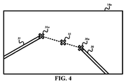
図3を参照すると、フローチャート40のステージS42は、当業者に知られるように、内視鏡12(図2)のFOV内において一つ又は複数の器具を検出し、トラッキングする可視性制御モジュール26(図2)を含み、フローチャート40のステージS44は、器具の間の空間点の選択に基づいて内視鏡12のFOV内における、検出される/トラッキングされる一つ又は複数の器具の可視性を維持するために内視鏡動きパラメータを計算するモジュール23を含む。 たとえば、図4の内視鏡画像14aにおいて示されるように、各々の器具30及び31の遠位チップ30a及び31aの間の空間点(例えば、中間点)が選択され、それによってロボット11(図2)は、内視鏡12(図2)を(例えば、横方向、縦方向及び/又は回転方向に)動かすように制御され、それによって空間点は内視鏡画像14aの中央33に位置される。実際、フローチャート40は、器具の全ての動きにより自動的に実行され得るか、又は入力装置(例えば、器具上のボタン、フットペダル、ボイスコマンド等)を介して制御ユニット20のオペレータによって実施され得る。
Referring to FIG. 3, stage S42 of flowchart 40 includes a
ステージS42の実施例において、当業者に知られるように、マークされ、又はマークされない器具が検出され、トラッキングされ得る。 In the embodiment of stage S42, as known to those skilled in the art, marked or unmarked instruments can be detected and tracked.
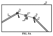
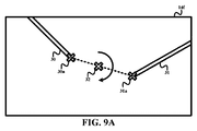
ステージS44のピボットモード実施例において、ズーム及び回転角が適切に仮定され、それによってロボット11は内視鏡12を横方向に動かすように制御され、それによって器具の間の空間点は内視鏡画像の中央にアラインされる。 たとえば、図5Aで示されるように、内視鏡ビュー14bは、内視鏡ビュー14bの中央から間隔を置いて配置される、遠位チップ30a及び31aの空間中間点33を示す。 したがって、ロボット11は、矢印によって示されるように、内視鏡12をピボットするように制御され、それによって空間中間点33は内視鏡ビュー14cの中央33にアラインされる。
In the pivot mode embodiment of stage S44, the zoom and rotation angles are properly assumed, whereby the
実際、制御オペレータが内視鏡12のFOV内における両方の器具を保つことを所望するが、他方の器具より高い一方の器具の重要性を考慮する場合、ロボット11が内視鏡画像の中央内において保つ空間点は、二つの器具の間の仮想ライン上における何れかの位置に存在し得る。 たとえば、器具30の可視性が重要であると見なされるか、又は器具31の可視性より高い優先度を有すると見なされる場合、図5の空間点33は、遠位チップ31aより遠位チップ30aに近くてもよい。
In fact, if the control operator wants to keep both instruments in the FOV of the
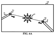
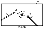
ステージS44のズームモード実施例(図2)において、横方向ポジショニング及び回転角は適切であると仮定され、それによって、ロボット11は内視鏡12を縦方向に動かすように制御され、それによって、器具が互いに向かって、又は互いから離れるように動かされるとき、内視鏡画像の中央における器具の間の空間点のアライメントが維持される。例えば図6Aは、器具30及び31が互いに向かって動かされているとき、内視鏡12を内視鏡画像14dの中央32の方へ縦方向に動かすことによって器具30及び31をズームインするための矢印を例示し、図6Bは、器具30及び31が互いから離れて動かされているとき、内視鏡12を内視鏡画像14eの中央32から離れるように縦方向に動かすことによって器具30及び31をズームアウトするための矢印を例示する。
In the zoom mode embodiment of stage S44 (FIG. 2), the lateral positioning and rotation angles are assumed to be appropriate, thereby controlling the
具体的には、内視鏡12のための1つのズーミング技術は、オンタッチスクリーン可能なパーソナルデバイスをズームイン及びズームアウトするために用いられる「ピンチトゥーズーム」ジェスチャーを実行する。具体的には、この制御モードが起動されるとき、仮想ラインは、図6に示されるように、二つの器具チップ30a及び31aの間に引かれる。図6Aに示されるように互いに向かって対向する矢印をつまむことによって画像の中央の方へ二つの器具チップを動かすステップ又は図6Bに示されるように他方から離れて対向する矢印をつまむことによって画像の中央から離れるように二つの器具チップを動かす(従って先端の間の距離を変化させる)ステップの何れかは、その主軸に沿う内視鏡の動きを制御するために用いられる。チップの間の距離の減少は、主軸に沿う内視鏡の変換をもたらすことが可能であり、従って内視鏡は器具により近くなり、又はその逆になる。
Specifically, one zooming technique for the
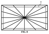
より具体的には、器具のトラッキングされる点のトラッキングベクトル50(例えば、器具の遠位チップ)は、ロボットベクトル51を構成し、それを内視鏡62のための挿入点61のまわりの二つの角度(φ、θ)として表されるエンドエフェクタポーズ60に変換するために用いられる。その主軸に沿う(すなわち挿入位置61から内及び外の)内視鏡62の動きは、内視鏡61の動きの結果として、画像における器具トラッキング点の動きを記述するトラッキングベクトルも生成するであろう。最も単純な場合において、画像平面が内視鏡軸と直角をなすことが仮定される場合、器具は画像中央から放射される光線に沿って画像上において動いており、トラッキングベクトル(vtrk)50はこれらの光線に沿っているであろう。従って、既知の速さ最適化計画が、(1)ロボット動きの方向は常に知られており、それは常にアウト(ズームアウト)され、ロボット停止基準は器具が境界領域(例えば、図8において示される境界領域70)の制限を横断する時であるという理解によりこの動きに使用されてもよい。
More specifically, the tracking
ステージS44の回転モード実施例(図2)において、横方向ポジショニング及びズーム角は適切であると仮定され、それによって、器具30及び31が解剖学的領域内において互いに対して回転されるとき、ロボット11は、内視鏡画像の中央に対する、器具の間の空間点のアライメントに従って内視鏡12を回転させるように制御される。
In the rotational mode embodiment of stage S44 (FIG. 2), the lateral positioning and zoom angles are assumed to be appropriate so that when the
図1に戻ると、実際、内視鏡ポーズコマンド28は、オペレータポーズコマンド27と同じ又は類似の形態を有する。具体的には、ジョイスティックの入力モジュールに類似するモジュール26が、モジュール24に対して、内視鏡12のための適切な横方向/縦方向の動き及び/又は回転度を決定し、伝える。代わりに、内視鏡ポーズコマンド28は、内視鏡画像の中央に対する器具の回転オフセット及び/又はミスアライメントの程度を示してもよく、モジュール24は内視鏡12のための適切な横方向/縦方向の動き及び/又は回転度の何れかの必要な計算を実行する。
Returning to FIG. 1, the
ここの図2-7の説明から、当業者は、限定されないが、一つ又は複数の器具がロボット内視鏡の視野内において適切な回転角度で常に見え得るロボット内視鏡のガイダンスを含む本発明の多数の利点を評価するであろう。 From the description of FIGS. 2-7 herein, one of ordinary skill in the art will be able to provide a book that includes, but is not limited to, a robot endoscope guidance where one or more instruments may always be visible at an appropriate rotation angle within the robot endoscope field of view. Many advantages of the invention will be appreciated.
本発明の好ましい実施例が図示されると共に記載されるが、本明細書に記載の実施例が図示を目的とするものであり、様々な変形及び修正がなされてもよく、同等のものが、本発明の範囲から逸脱することなく、本発明の構成要素の代わりに使用されてもよいことは当業者によって理解されるであろう。更に、本発明の範囲から逸脱することなく、本発明の教示を特定の状況に適用するために多くの変形がなされてもよい。それ故に本発明が、本発明を実施するように意図されるベストモードとして開示される特定の実施例に限定されるものではないが、本発明が特許請求内における全ての実施例を含むことは意図される。 While the preferred embodiments of the invention have been illustrated and described, the embodiments described herein are for purposes of illustration and various variations and modifications may be made, It will be appreciated by those skilled in the art that instead of components of the present invention may be used without departing from the scope of the present invention. In addition, many modifications may be made to apply a teaching of the invention to a particular situation without departing from the scope of the invention. Therefore, the invention is not limited to the specific embodiments disclosed as the best mode intended to practice the invention, but it is intended that the invention includes all embodiments within the scope of the claims. Intended.
Claims (20)
ロボットアクチュエータコマンドに応答して前記解剖学的領域内において前記内視鏡を動かすように前記内視鏡に可動的に接続されるロボット
を含むロボットユニットと、
前記解剖学的領域の前記内視鏡画像の表示を制御するように前記内視鏡に可動的に接続され、前記内視鏡画像の中央に対して前記内視鏡画像の前記表示内において少なくとも二つの介入器具の可視性を維持するように内視鏡ポーズコマンドを生成するように動作可能な内視鏡画像コントローラ、及び
前記内視鏡ポーズコマンドに応答して前記ロボットアクチュエータコマンドを生成するように前記内視鏡画像コントローラ及び前記ロボットに可動的に接続されるロボットコントローラ
を含む制御ユニットと
を有する、ロボットガイドシステム。 An endoscope operable to generate an endoscopic image of the anatomical region, and movable to the endoscope to move the endoscope within the anatomical region in response to a robot actuator command A robot unit including a robot to be connected
Movably connected to the endoscope to control display of the endoscopic image of the anatomical region, and at least within the display of the endoscopic image relative to a center of the endoscopic image An endoscopic image controller operable to generate an endoscope pose command to maintain visibility of two interventional instruments, and to generate the robot actuator command in response to the endoscope pose command A control unit including the endoscope image controller and a robot controller movably connected to the robot.
前記解剖学的領域の前記内視鏡画像の表示を制御するように動作可能であり、前記内視鏡画像の中央に対して前記内視鏡画像の前記表示内において少なくとも二つの介入器具の可視性を維持するように内視鏡ポーズコマンドを生成するように動作可能である内視鏡画像コントローラ、及び
前記内視鏡ポーズコマンドに応答してロボットアクチュエータコマンドを生成するように前記内視鏡画像コントローラに可動的に接続されるロボットコントローラ
を有する、制御ユニット。 A control unit for a robot connected to an endoscope for generating an endoscopic image of an anatomical region, the control unit comprising:
Visible to control the display of the endoscopic image of the anatomical region and visible of at least two interventional instruments within the display of the endoscopic image relative to the center of the endoscopic image An endoscopic image controller operable to generate an endoscopic pause command so as to maintain operability, and the endoscopic image to generate a robot actuator command in response to the endoscopic pause command A control unit having a robot controller movably connected to the controller.
前記内視鏡画像コントローラは、前記解剖学的領域内において互いから離れるように動かされる前記少なくとも二つの介入器具に応答して前記内視鏡画像の中央に対して前記内視鏡画像の前記表示内において少なくとも二つの介入器具の可視性を維持するように、前記内視鏡を縦方向に動かす前記内視鏡ポーズコマンドを生成する、請求項12に記載の制御ユニット。 The endoscopic image controller is configured to display the endoscopic image within the display of the endoscopic image relative to a center of the endoscopic image in response to the at least two interventional instruments being moved toward each other within the anatomical region. Generating the endoscope pause command to move the endoscope longitudinally to maintain visibility of at least two interventional instruments at
The endoscopic image controller is configured to display the endoscopic image relative to a center of the endoscopic image in response to the at least two interventional instruments being moved away from each other within the anatomical region. The control unit of claim 12, wherein the control unit generates the endoscope pause command to move the endoscope longitudinally so as to maintain visibility of at least two interventional instruments therein.
前記内視鏡が前記解剖学的領域の前記内視鏡画像を生成しているとき、前記解剖学的領域内において前記内視鏡を動かすようにロボットに命令するステップと
を有する、ロボットガイド方法において、
前記ロボットに命令するステップは、前記内視鏡画像の中央に対して前記内視鏡画像の前記表示内において少なくとも二つの介入器具の可視性を維持する、
ロボットガイド方法。 Operating the endoscope to generate and display an endoscopic image of the anatomical region;
Instructing the robot to move the endoscope within the anatomical region when the endoscope is generating the endoscopic image of the anatomical region. In
Commanding the robot maintains the visibility of at least two interventional instruments in the display of the endoscopic image relative to the center of the endoscopic image;
Robot guide method.
前記ロボットは、前記解剖学的領域内において他方から離れるように動かされる前記少なくとも二つの介入器具に応答して前記内視鏡画像の中央に対して前記内視鏡画像の前記表示内において少なくとも二つの介入器具の可視性を維持するように、前記内視鏡を縦方向に動かすように命令される、
請求項17に記載のロボットガイド方法。 The robot is at least two in the display of the endoscopic image relative to the center of the endoscopic image in response to the at least two interventional instruments being moved toward each other within the anatomical region. Commanded to move the endoscope longitudinally to maintain the visibility of the interventional instrument;
The robot is at least two in the display of the endoscopic image relative to the center of the endoscopic image in response to the at least two interventional instruments being moved away from the other in the anatomical region. Commanded to move the endoscope longitudinally to maintain the visibility of two interventional instruments;
The robot guide method according to claim 17.
Priority Applications (1)
| Application Number | Priority Date | Filing Date | Title |
|---|---|---|---|
| JP2019221910A JP6982605B2 (en) | 2014-02-12 | 2019-12-09 | Surgical instrument visibility robot control |
Applications Claiming Priority (3)
| Application Number | Priority Date | Filing Date | Title |
|---|---|---|---|
| US201461938721P | 2014-02-12 | 2014-02-12 | |
| US61/938,721 | 2014-02-12 | ||
| PCT/IB2015/050665 WO2015121765A1 (en) | 2014-02-12 | 2015-01-29 | Robotic control of surgical instrument visibility |
Related Child Applications (1)
| Application Number | Title | Priority Date | Filing Date |
|---|---|---|---|
| JP2019221910A Division JP6982605B2 (en) | 2014-02-12 | 2019-12-09 | Surgical instrument visibility robot control |
Publications (2)
| Publication Number | Publication Date |
|---|---|
| JP2017505202A true JP2017505202A (en) | 2017-02-16 |
| JP2017505202A5 JP2017505202A5 (en) | 2018-03-01 |
Family
ID=52629630
Family Applications (2)
| Application Number | Title | Priority Date | Filing Date |
|---|---|---|---|
| JP2016550719A Pending JP2017505202A (en) | 2014-02-12 | 2015-01-29 | Surgical instrument visibility robotic control |
| JP2019221910A Active JP6982605B2 (en) | 2014-02-12 | 2019-12-09 | Surgical instrument visibility robot control |
Family Applications After (1)
| Application Number | Title | Priority Date | Filing Date |
|---|---|---|---|
| JP2019221910A Active JP6982605B2 (en) | 2014-02-12 | 2019-12-09 | Surgical instrument visibility robot control |
Country Status (5)
| Country | Link |
|---|---|
| US (1) | US10945796B2 (en) |
| EP (1) | EP3104804B1 (en) |
| JP (2) | JP2017505202A (en) |
| CN (1) | CN105992568B (en) |
| WO (1) | WO2015121765A1 (en) |
Cited By (3)
| Publication number | Priority date | Publication date | Assignee | Title |
|---|---|---|---|---|
| JP2018143560A (en) * | 2017-01-03 | 2018-09-20 | 上銀科技股▲フン▼有限公司 | System and method for manipulating endoscope |
| WO2023022257A1 (en) * | 2021-08-19 | 2023-02-23 | 한국로봇융합연구원 | System and method for controlling laparoscope camera holder robot |
| WO2023145285A1 (en) * | 2022-01-26 | 2023-08-03 | オリンパス株式会社 | Endoscope system, endoscope system control method and recording medium |
Families Citing this family (30)
| Publication number | Priority date | Publication date | Assignee | Title |
|---|---|---|---|---|
| WO2015118422A1 (en) * | 2014-02-04 | 2015-08-13 | Koninklijke Philips N.V. | Remote center of motion definition using light sources for robot systems |
| EP4233768A3 (en) | 2014-03-17 | 2023-12-27 | Intuitive Surgical Operations, Inc. | Device and machine readable medium executing a method of recentering end effectors and input controls |
| EP3632364B1 (en) | 2014-03-17 | 2021-09-01 | Intuitive Surgical Operations, Inc. | Indicator mechanism for an actuator controlled surgical instrument |
| US20170202624A1 (en) * | 2014-06-08 | 2017-07-20 | M.S.T. Medical Surgery Technologies Ltd | Device and method for assisting laparoscopic surgery utilizing a touch screen |
| WO2016063682A1 (en) * | 2014-10-22 | 2016-04-28 | オリンパス株式会社 | Endoscope insertion shape observation device |
| US20160206179A1 (en) * | 2015-01-15 | 2016-07-21 | National Taiwan University | Assistive robot endoscopic system with intuitive maneuverability for laparoscopic surgery and method thereof |
| CN106999254B (en) * | 2015-02-26 | 2019-09-03 | 奥林巴斯株式会社 | Arm-and-hand system |
| US10973595B2 (en) * | 2015-08-13 | 2021-04-13 | Siemens Healthcare Gmbh | Device and method for controlling a system comprising an imaging modality |
| JP6886968B2 (en) * | 2015-10-09 | 2021-06-16 | コヴィディエン リミテッド パートナーシップ | How to use an angled endoscope to visualize body cavities using a robotic surgical system |
| US11344379B2 (en) | 2016-12-07 | 2022-05-31 | Koninklijke Philips N.V. | Automatic motion control of a dependent surgical robotic arm |
| WO2018225132A1 (en) * | 2017-06-05 | 2018-12-13 | オリンパス株式会社 | Medical system and method for operating medical system |
| WO2019006028A1 (en) * | 2017-06-28 | 2019-01-03 | Intuitive Surgical Operations, Inc. | Systems and methods for projecting an endoscopic image to a three-dimensional volume |
| EP3649918B1 (en) * | 2017-07-03 | 2023-08-02 | FUJIFILM Corporation | Medical image processing device, endoscope device, diagnostic support device, medical service support device and report generation support device |
| WO2019087904A1 (en) * | 2017-11-01 | 2019-05-09 | ソニー株式会社 | Surgical arm system and surgical arm control system |
| US20210059775A1 (en) * | 2018-01-10 | 2021-03-04 | Covidien Lp | Determining positions and conditions of tools of a robotic surgical system utilizing computer vision |
| US20200015904A1 (en) | 2018-07-16 | 2020-01-16 | Ethicon Llc | Surgical visualization controls |
| US11896442B2 (en) | 2019-12-30 | 2024-02-13 | Cilag Gmbh International | Surgical systems for proposing and corroborating organ portion removals |
| US11832996B2 (en) | 2019-12-30 | 2023-12-05 | Cilag Gmbh International | Analyzing surgical trends by a surgical system |
| US11744667B2 (en) | 2019-12-30 | 2023-09-05 | Cilag Gmbh International | Adaptive visualization by a surgical system |
| US11648060B2 (en) | 2019-12-30 | 2023-05-16 | Cilag Gmbh International | Surgical system for overlaying surgical instrument data onto a virtual three dimensional construct of an organ |
| US11219501B2 (en) | 2019-12-30 | 2022-01-11 | Cilag Gmbh International | Visualization systems using structured light |
| US11759283B2 (en) | 2019-12-30 | 2023-09-19 | Cilag Gmbh International | Surgical systems for generating three dimensional constructs of anatomical organs and coupling identified anatomical structures thereto |
| US11284963B2 (en) | 2019-12-30 | 2022-03-29 | Cilag Gmbh International | Method of using imaging devices in surgery |
| US11776144B2 (en) | 2019-12-30 | 2023-10-03 | Cilag Gmbh International | System and method for determining, adjusting, and managing resection margin about a subject tissue |
| CN112450996A (en) * | 2020-11-11 | 2021-03-09 | 北京科迈启元科技有限公司 | Flexible endoscope operation executor and operation robot system |
| USD1022197S1 (en) | 2020-11-19 | 2024-04-09 | Auris Health, Inc. | Endoscope |
| CN112587244A (en) * | 2020-12-15 | 2021-04-02 | 深圳市精锋医疗科技有限公司 | Surgical robot and control method and control device thereof |
| CN113855257B (en) * | 2021-11-05 | 2024-03-12 | 佗道医疗科技有限公司 | Self-adaptive adjusting method for endoscope pose |
| CN113786152B (en) * | 2021-11-17 | 2022-02-08 | 极限人工智能有限公司 | Endoscope lens tracking method and endoscope system |
| JP2023180371A (en) * | 2022-06-09 | 2023-12-21 | 株式会社メディカロイド | Surgery system |
Citations (3)
| Publication number | Priority date | Publication date | Assignee | Title |
|---|---|---|---|---|
| JP2008228967A (en) * | 2007-03-20 | 2008-10-02 | Hitachi Ltd | Master-slave manipulator system |
| US20090245600A1 (en) * | 2008-03-28 | 2009-10-01 | Intuitive Surgical, Inc. | Automated panning and digital zooming for robotic surgical systems |
| WO2013093761A2 (en) * | 2011-12-21 | 2013-06-27 | Koninklijke Philips Electronics N.V. | Overlay and motion compensation of structures from volumetric modalities onto video of an uncalibrated endoscope |
Family Cites Families (19)
| Publication number | Priority date | Publication date | Assignee | Title |
|---|---|---|---|---|
| US5417210A (en) | 1992-05-27 | 1995-05-23 | International Business Machines Corporation | System and method for augmentation of endoscopic surgery |
| US6463361B1 (en) | 1994-09-22 | 2002-10-08 | Computer Motion, Inc. | Speech interface for an automated endoscopic system |
| US5825982A (en) | 1995-09-15 | 1998-10-20 | Wright; James | Head cursor control interface for an automated endoscope system for optimal positioning |
| EP2316328B1 (en) * | 2003-09-15 | 2012-05-09 | Super Dimension Ltd. | Wrap-around holding device for use with bronchoscopes |
| US8147503B2 (en) * | 2007-09-30 | 2012-04-03 | Intuitive Surgical Operations Inc. | Methods of locating and tracking robotic instruments in robotic surgical systems |
| US10258425B2 (en) * | 2008-06-27 | 2019-04-16 | Intuitive Surgical Operations, Inc. | Medical robotic system providing an auxiliary view of articulatable instruments extending out of a distal end of an entry guide |
| US8620473B2 (en) * | 2007-06-13 | 2013-12-31 | Intuitive Surgical Operations, Inc. | Medical robotic system with coupled control modes |
| US20090074265A1 (en) * | 2007-09-17 | 2009-03-19 | Capsovision Inc. | Imaging review and navigation workstation system |
| US20100111389A1 (en) * | 2007-12-06 | 2010-05-06 | Siemens Medical Solutions Usa, Inc. | System and method for planning and guiding percutaneous procedures |
| JPWO2009084345A1 (en) * | 2007-12-28 | 2011-05-19 | オリンパスメディカルシステムズ株式会社 | Medical equipment system |
| US8864652B2 (en) * | 2008-06-27 | 2014-10-21 | Intuitive Surgical Operations, Inc. | Medical robotic system providing computer generated auxiliary views of a camera instrument for controlling the positioning and orienting of its tip |
| US20100331856A1 (en) * | 2008-12-12 | 2010-12-30 | Hansen Medical Inc. | Multiple flexible and steerable elongate instruments for minimally invasive operations |
| JP5814938B2 (en) | 2010-01-08 | 2015-11-17 | コーニンクレッカ フィリップス エヌ ヴェKoninklijke Philips N.V. | Calibration-free visual servo using real-time speed optimization |
| JP6053673B2 (en) * | 2011-04-28 | 2016-12-27 | オリンパス株式会社 | Fluorescence observation apparatus and image display method thereof |
| US10092164B2 (en) * | 2011-08-21 | 2018-10-09 | M.S.T. Medical Surgery Technologies Ltd | Device and method for assisting laparoscopic surgery—rule based approach |
| EP3760389A1 (en) * | 2012-02-15 | 2021-01-06 | Intuitive Surgical Operations, Inc. | Switching control of an instrument to an input device upon the instrument entering a display area viewable by an operator of the input device |
| US9545192B2 (en) * | 2012-05-04 | 2017-01-17 | Given Imaging Ltd. | System and method for automatic navigation of a capsule based on image stream captured in-vivo |
| TWI517828B (en) * | 2012-06-27 | 2016-01-21 | 國立交通大學 | Image tracking system and image tracking method thereof |
| CN106030683B (en) * | 2013-12-20 | 2020-10-30 | 直观外科手术操作公司 | Simulator system for medical procedure training |
-
2015
- 2015-01-29 WO PCT/IB2015/050665 patent/WO2015121765A1/en active Application Filing
- 2015-01-29 JP JP2016550719A patent/JP2017505202A/en active Pending
- 2015-01-29 US US15/117,001 patent/US10945796B2/en active Active
- 2015-01-29 EP EP15708304.9A patent/EP3104804B1/en active Active
- 2015-01-29 CN CN201580008132.1A patent/CN105992568B/en active Active
-
2019
- 2019-12-09 JP JP2019221910A patent/JP6982605B2/en active Active
Patent Citations (3)
| Publication number | Priority date | Publication date | Assignee | Title |
|---|---|---|---|---|
| JP2008228967A (en) * | 2007-03-20 | 2008-10-02 | Hitachi Ltd | Master-slave manipulator system |
| US20090245600A1 (en) * | 2008-03-28 | 2009-10-01 | Intuitive Surgical, Inc. | Automated panning and digital zooming for robotic surgical systems |
| WO2013093761A2 (en) * | 2011-12-21 | 2013-06-27 | Koninklijke Philips Electronics N.V. | Overlay and motion compensation of structures from volumetric modalities onto video of an uncalibrated endoscope |
Cited By (4)
| Publication number | Priority date | Publication date | Assignee | Title |
|---|---|---|---|---|
| JP2018143560A (en) * | 2017-01-03 | 2018-09-20 | 上銀科技股▲フン▼有限公司 | System and method for manipulating endoscope |
| US10624525B2 (en) | 2017-01-03 | 2020-04-21 | Hiwin Technologies Corp. | Endoscopic system and method for controlling the same |
| WO2023022257A1 (en) * | 2021-08-19 | 2023-02-23 | 한국로봇융합연구원 | System and method for controlling laparoscope camera holder robot |
| WO2023145285A1 (en) * | 2022-01-26 | 2023-08-03 | オリンパス株式会社 | Endoscope system, endoscope system control method and recording medium |
Also Published As
| Publication number | Publication date |
|---|---|
| CN105992568B (en) | 2018-06-08 |
| US10945796B2 (en) | 2021-03-16 |
| CN105992568A (en) | 2016-10-05 |
| EP3104804A1 (en) | 2016-12-21 |
| JP6982605B2 (en) | 2021-12-17 |
| WO2015121765A1 (en) | 2015-08-20 |
| EP3104804B1 (en) | 2021-12-15 |
| US20160354166A1 (en) | 2016-12-08 |
| JP2020039934A (en) | 2020-03-19 |
Similar Documents
| Publication | Publication Date | Title |
|---|---|---|
| JP6982605B2 (en) | Surgical instrument visibility robot control | |
| US11413099B2 (en) | System, controller and method using virtual reality device for robotic surgery | |
| CN108472090B (en) | System, control unit and method for controlling a surgical robot | |
| US10675105B2 (en) | Controller definition of a robotic remote center of motion | |
| EP2822445B1 (en) | Overall endoscopic control system | |
| JP6629186B2 (en) | Robot control of endoscope from anatomical features | |
| CN105616007B (en) | Medical robotic system with coordinated type control model | |
| US20190069955A1 (en) | Control unit, system and method for controlling hybrid robot having rigid proximal portion and flexible distal portion | |
| JP2021531910A (en) | Robot-operated surgical instrument location tracking system and method | |
| JP6975131B2 (en) | Endoscopic guidance from an interactive planar slice of a volume image | |
| WO2015110929A1 (en) | Robotic control of an endoscope orientation |
Legal Events
| Date | Code | Title | Description |
|---|---|---|---|
| RD04 | Notification of resignation of power of attorney |
Free format text: JAPANESE INTERMEDIATE CODE: A7424 Effective date: 20170214 |
|
| A521 | Request for written amendment filed |
Free format text: JAPANESE INTERMEDIATE CODE: A523 Effective date: 20180116 |
|
| A621 | Written request for application examination |
Free format text: JAPANESE INTERMEDIATE CODE: A621 Effective date: 20180116 |
|
| A977 | Report on retrieval |
Free format text: JAPANESE INTERMEDIATE CODE: A971007 Effective date: 20181025 |
|
| A131 | Notification of reasons for refusal |
Free format text: JAPANESE INTERMEDIATE CODE: A131 Effective date: 20181108 |
|
| A601 | Written request for extension of time |
Free format text: JAPANESE INTERMEDIATE CODE: A601 Effective date: 20190207 |
|
| A521 | Request for written amendment filed |
Free format text: JAPANESE INTERMEDIATE CODE: A523 Effective date: 20190423 |
|
| A02 | Decision of refusal |
Free format text: JAPANESE INTERMEDIATE CODE: A02 Effective date: 20190808 |
|
| A521 | Request for written amendment filed |
Free format text: JAPANESE INTERMEDIATE CODE: A523 Effective date: 20191209 |
|
| C60 | Trial request (containing other claim documents, opposition documents) |
Free format text: JAPANESE INTERMEDIATE CODE: C60 Effective date: 20191209 |
|
| A911 | Transfer to examiner for re-examination before appeal (zenchi) |
Free format text: JAPANESE INTERMEDIATE CODE: A911 Effective date: 20191216 |
|
| C21 | Notice of transfer of a case for reconsideration by examiners before appeal proceedings |
Free format text: JAPANESE INTERMEDIATE CODE: C21 Effective date: 20191217 |
|
| A912 | Re-examination (zenchi) completed and case transferred to appeal board |
Free format text: JAPANESE INTERMEDIATE CODE: A912 Effective date: 20200110 |
|
| C211 | Notice of termination of reconsideration by examiners before appeal proceedings |
Free format text: JAPANESE INTERMEDIATE CODE: C211 Effective date: 20200116 |
|
| C22 | Notice of designation (change) of administrative judge |
Free format text: JAPANESE INTERMEDIATE CODE: C22 Effective date: 20200402 |
|
| C13 | Notice of reasons for refusal |
Free format text: JAPANESE INTERMEDIATE CODE: C13 Effective date: 20200728 |
|
| A601 | Written request for extension of time |
Free format text: JAPANESE INTERMEDIATE CODE: A601 Effective date: 20201023 |
|
| C23 | Notice of termination of proceedings |
Free format text: JAPANESE INTERMEDIATE CODE: C23 Effective date: 20210225 |
|
| C03 | Trial/appeal decision taken |
Free format text: JAPANESE INTERMEDIATE CODE: C03 Effective date: 20210325 |
|
| C30A | Notification sent |
Free format text: JAPANESE INTERMEDIATE CODE: C3012 Effective date: 20210325 |