JP2017046988A - Drawing deice, method for operation control of drawing device, and program for operation control of drawing device - Google Patents
Drawing deice, method for operation control of drawing device, and program for operation control of drawing device Download PDFInfo
- Publication number
- JP2017046988A JP2017046988A JP2015173461A JP2015173461A JP2017046988A JP 2017046988 A JP2017046988 A JP 2017046988A JP 2015173461 A JP2015173461 A JP 2015173461A JP 2015173461 A JP2015173461 A JP 2015173461A JP 2017046988 A JP2017046988 A JP 2017046988A
- Authority
- JP
- Japan
- Prior art keywords
- pen
- unit
- color
- drawn
- image
- Prior art date
- Legal status (The legal status is an assumption and is not a legal conclusion. Google has not performed a legal analysis and makes no representation as to the accuracy of the status listed.)
- Pending
Links
- 238000000034 method Methods 0.000 title claims abstract description 19
- 238000003384 imaging method Methods 0.000 claims abstract description 50
- 238000013461 design Methods 0.000 claims abstract description 27
- 238000012790 confirmation Methods 0.000 claims description 5
- 239000003086 colorant Substances 0.000 abstract description 8
- 210000000282 nail Anatomy 0.000 description 32
- 238000012545 processing Methods 0.000 description 19
- 238000012360 testing method Methods 0.000 description 8
- 238000003780 insertion Methods 0.000 description 7
- 230000037431 insertion Effects 0.000 description 7
- 230000006870 function Effects 0.000 description 6
- 230000008569 process Effects 0.000 description 5
- 210000004905 finger nail Anatomy 0.000 description 4
- 238000010586 diagram Methods 0.000 description 3
- 230000008901 benefit Effects 0.000 description 1
- 210000000078 claw Anatomy 0.000 description 1
- 239000011248 coating agent Substances 0.000 description 1
- 238000000576 coating method Methods 0.000 description 1
- 238000001514 detection method Methods 0.000 description 1
- 238000009434 installation Methods 0.000 description 1
- 230000007246 mechanism Effects 0.000 description 1
- 238000012986 modification Methods 0.000 description 1
- 230000004048 modification Effects 0.000 description 1
- 210000004906 toe nail Anatomy 0.000 description 1
Images


Classifications
-
- A—HUMAN NECESSITIES
- A45—HAND OR TRAVELLING ARTICLES
- A45D—HAIRDRESSING OR SHAVING EQUIPMENT; EQUIPMENT FOR COSMETICS OR COSMETIC TREATMENTS, e.g. FOR MANICURING OR PEDICURING
- A45D29/00—Manicuring or pedicuring implements
-
- B—PERFORMING OPERATIONS; TRANSPORTING
- B43—WRITING OR DRAWING IMPLEMENTS; BUREAU ACCESSORIES
- B43L—ARTICLES FOR WRITING OR DRAWING UPON; WRITING OR DRAWING AIDS; ACCESSORIES FOR WRITING OR DRAWING
- B43L13/00—Drawing instruments, or writing or drawing appliances or accessories not otherwise provided for
- B43L13/02—Draughting machines or drawing devices for keeping parallelism
- B43L13/022—Draughting machines or drawing devices for keeping parallelism automatic
- B43L13/024—Drawing heads therefor
-
- G—PHYSICS
- G06—COMPUTING; CALCULATING OR COUNTING
- G06F—ELECTRIC DIGITAL DATA PROCESSING
- G06F3/00—Input arrangements for transferring data to be processed into a form capable of being handled by the computer; Output arrangements for transferring data from processing unit to output unit, e.g. interface arrangements
- G06F3/002—Specific input/output arrangements not covered by G06F3/01 - G06F3/16
- G06F3/005—Input arrangements through a video camera
-
- G—PHYSICS
- G06—COMPUTING; CALCULATING OR COUNTING
- G06K—GRAPHICAL DATA READING; PRESENTATION OF DATA; RECORD CARRIERS; HANDLING RECORD CARRIERS
- G06K15/00—Arrangements for producing a permanent visual presentation of the output data, e.g. computer output printers
- G06K15/02—Arrangements for producing a permanent visual presentation of the output data, e.g. computer output printers using printers
- G06K15/021—Adaptations for printing on specific media
-
- G—PHYSICS
- G06—COMPUTING; CALCULATING OR COUNTING
- G06K—GRAPHICAL DATA READING; PRESENTATION OF DATA; RECORD CARRIERS; HANDLING RECORD CARRIERS
- G06K15/00—Arrangements for producing a permanent visual presentation of the output data, e.g. computer output printers
- G06K15/40—Details not directly involved in printing, e.g. machine management, management of the arrangement as a whole or of its constitutive parts
- G06K15/407—Managing marking material, e.g. checking available colours
-
- G—PHYSICS
- G06—COMPUTING; CALCULATING OR COUNTING
- G06T—IMAGE DATA PROCESSING OR GENERATION, IN GENERAL
- G06T11/00—2D [Two Dimensional] image generation
- G06T11/20—Drawing from basic elements, e.g. lines or circles
-
- A—HUMAN NECESSITIES
- A45—HAND OR TRAVELLING ARTICLES
- A45D—HAIRDRESSING OR SHAVING EQUIPMENT; EQUIPMENT FOR COSMETICS OR COSMETIC TREATMENTS, e.g. FOR MANICURING OR PEDICURING
- A45D29/00—Manicuring or pedicuring implements
- A45D2029/005—Printing or stamping devices for applying images or ornaments to nails
-
- A—HUMAN NECESSITIES
- A45—HAND OR TRAVELLING ARTICLES
- A45D—HAIRDRESSING OR SHAVING EQUIPMENT; EQUIPMENT FOR COSMETICS OR COSMETIC TREATMENTS, e.g. FOR MANICURING OR PEDICURING
- A45D44/00—Other cosmetic or toiletry articles, e.g. for hairdressers' rooms
- A45D44/005—Other cosmetic or toiletry articles, e.g. for hairdressers' rooms for selecting or displaying personal cosmetic colours or hairstyle
Abstract
Description
本発明は、描画装置、描画装置の動作制御方法及び描画装置の動作制御プログラムに関する。 The present invention relates to a drawing device, a drawing device operation control method, and a drawing device operation control program.
例えば、特許文献1に、指をロックするためのホルダーを備えて指の爪にネイルデザインを描くネイルアート装置が開示されている。特許文献1に開示されたネイルアート装置では、インクジェットプリンタを用いて爪にネイルデザインが印刷されている。 For example, Patent Document 1 discloses a nail art apparatus that includes a holder for locking a finger and draws a nail design on a fingernail. In the nail art apparatus disclosed in Patent Document 1, a nail design is printed on a nail using an ink jet printer.
ところで、この種の装置にペンを用いて描画するペンプロッタの構成を用いれば、印刷では難しい処理等が実行できるようになる。この場合には、各色のペンの装着位置が指定されて、指定された装着位置に指定された色のペンを装着することになる。
このため、指定された装着位置に誤った色のペンを装着した場合には、間違った色のペンを使用してネイルデザインを描画してしまうことになり、ネイルデザインの描画が失敗してしまうという問題がある。
By the way, if a configuration of a pen plotter that draws with a pen is used in this type of apparatus, processing that is difficult in printing can be performed. In this case, the pen mounting position for each color is specified, and the pen of the specified color is mounted at the specified mounting position.
For this reason, if the wrong color pen is attached to the specified attachment position, the nail design will be drawn using the wrong color pen, and the nail design drawing will fail. There is a problem.
本発明は、上記のような事情に鑑みてなされたものであり、ネイルデザインの描画に必要な色を描画するペンを装置のどの装着位置に装着しても正しい色を描画するペンを用いてネイルデザインを描画することができる描画装置、描画装置の動作制御方法及び描画装置の動作制御プログラムを提供することを目的とする。 The present invention has been made in view of the above-described circumstances, and uses a pen that draws a correct color regardless of the attachment position of the apparatus for drawing a color necessary for drawing a nail design. An object of the present invention is to provide a drawing apparatus capable of drawing a nail design, an operation control method for the drawing apparatus, and an operation control program for the drawing apparatus.
上記課題を解決するため、本発明の描画装置、描画装置の動作制御方法及び描画装置の動作制御プログラムは、以下のような解決手段を提供する。 In order to solve the above problems, the drawing apparatus, the drawing apparatus operation control method, and the drawing apparatus operation control program of the present invention provide the following solution.
本発明の描画装置は、描画対象に描画を施す少なくとも一つの描画用具が装着される少なくとも一つの描画用具配置部と、前記描画用具が描画する色を識別するための識別画像を取得する撮像部と、取得した前記識別画像に基づき、前記描画用具配置部に装着されている前記描画用具が描画する色を識別する制御部と、を備えることを特徴とする。 The drawing apparatus of the present invention includes at least one drawing tool placement unit on which at least one drawing tool for drawing a drawing target is mounted, and an imaging unit that acquires an identification image for identifying a color drawn by the drawing tool. And a control unit for identifying a color drawn by the drawing tool mounted on the drawing tool placement unit based on the acquired identification image.
本発明の描画装置の動作制御方法は、描画装置の動作制御方法であって、前記描画装置は、描画対象に描画を施す少なくとも一つの描画用具が装着される少なくとも一つの描画用具配置部と、撮像部と、を有し、前記撮像部により、前記描画用具が描画する色を識別するための識別画像を取得するステップと、取得した前記識別画像に基づき、前記描画用具配置部に装着されている前記描画用具が描画する色を識別するステップと、を含むことを特徴とする。 An operation control method for a drawing apparatus according to the present invention is an operation control method for a drawing apparatus, wherein the drawing apparatus includes at least one drawing tool placement unit to which at least one drawing tool for drawing a drawing target is attached; An imaging unit, and the imaging unit acquires an identification image for identifying a color drawn by the drawing tool, and is attached to the drawing tool placement unit based on the acquired identification image. Identifying a color to be drawn by the drawing tool.
本発明の描画装置の動作制御プログラムは、描画装置の動作制御プログラムであって、前記描画装置は、描画対象に描画を施す少なくとも一つの描画用具が装着される少なくとも一つの描画用具配置部と撮像部とを有し、前記描画装置に、前記撮像部により、前記描画用具が描画する色を識別するための識別画像を取得させる機能と、取得した前記識別画像に基づき、前記描画用具配置部に装着されている前記描画用具が描画する色を識別させる機能と、を実現させることを特徴とする。 An operation control program for a drawing apparatus according to the present invention is an operation control program for a drawing apparatus, and the drawing apparatus includes at least one drawing tool placement unit on which at least one drawing tool for drawing a drawing target is mounted, and imaging. A function for causing the drawing device to acquire an identification image for identifying a color to be drawn by the drawing tool, and the drawing tool placement unit based on the acquired identification image. And a function of recognizing a color to be drawn by the attached drawing tool.
本発明によれば、ネイルデザインの描画に必要な色を描画するペンを装置のどの装着位置に装着しても正しい色を描画するペンを用いてネイルデザインを描画することができる描画装置、描画装置の動作制御方法及び描画装置の動作制御プログラムを提供する。 ADVANTAGE OF THE INVENTION According to this invention, the drawing apparatus which can draw a nail design using the pen which draws a correct color, regardless of the mounting position of the apparatus which draws the color required for drawing of a nail design, and drawing An apparatus operation control method and a drawing apparatus operation control program are provided.
以下、添付図面を参照して、本発明を実施するための形態(以下、実施形態)について詳細に説明する。以降の図においては、実施形態の説明の全体を通して同じ要素には同じ番号又は符号を付している。 DESCRIPTION OF EMBODIMENTS Hereinafter, embodiments for carrying out the present invention (hereinafter referred to as embodiments) will be described in detail with reference to the accompanying drawings. In the subsequent drawings, the same numbers or symbols are assigned to the same elements throughout the description of the embodiments.
また、以下の実施形態では、描画装置は手の指の爪を描画対象として、これに描画するものとして説明するが、本発明の描画対象は手の指の爪に限るものではなく、例えば足の指の爪を描画対象としてもよい。 In the following embodiments, the drawing apparatus will be described assuming that the fingernail of the hand is drawn on the drawing object, but the drawing object of the present invention is not limited to the fingernail of the hand. The fingernail may be drawn.
(第1実施形態)
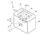
図1は本発明に係る第1実施形態の描画装置の外観を概念的に示す図である。
(First embodiment)
FIG. 1 is a diagram conceptually showing the appearance of the drawing apparatus according to the first embodiment of the present invention.
図1に示すように、描画装置10は、例えば、人の指12の爪11にネイルデザインを描画する装置である。
描画装置10は、ケース本体20と、ケース本体20の上面(天板)に設けられる、操作部21を兼ね備えたタッチパネル式の表示部22とを備える。
As shown in FIG. 1, the
The
そして、ケース本体20には、その前面に開口する指挿入部23が設けられている。
また、ケース本体20の内部には、インクジェット部24及び描画ヘッド部25(例えば、描画対象に描画を施すペン(描画用具)30を用いるペンプロッタ)とからなる描画部26と、撮像部40(例えば、カメラ)と、が設けられている。
The
Further, inside the
さらに、ケース本体20の内部には、不使用時のペン(描画用具)30の待機位置に、複数のペン(描画用具)30に対応する複数のペン配置部(描画用具配置部)50が設けられ、複数のペン30の各々は、非描画時に、複数のペン配置部50の各々に装着される。
ペン配置部50は、ペン30が装着されているか否かを検知することができる、例えばペン30が装着されているときにオンし装着されていないときにオフする、装着検知スイッチ(図示せず)を有している。
また、ケース本体20内のペン配置部50の近傍には、ペン30を交換するための図示しない扉が設けられており、その扉を開けることで、使用者は、ペン配置部50に配置されているペン30を交換することができる。
Further, inside the case
The
In addition, a door (not shown) for replacing the
さらに、ペン30、インクジェット部24、及び撮像部40は、各種の移動手段(図示省略)によって、図中に破線の矢印で示すように、前後方向や左右方向、また必要に応じて上下方向に移動可能になっている。
Further, the
続いて、描画装置10の制御系の構成を図2に基づいて説明する。図2は、本発明に係る第1実施形態の制御系の構成を示すブロック図である。
Next, the configuration of the control system of the
図2に示すように、制御装置70は、CPU(Central Processing Unit)により構成される制御部71と、ROM(Read Only Memory)及びRAM(Random Access Memory)等で構成される記憶部74とを備える。
As shown in FIG. 2, the
制御部71は、描画制御部72及びペン識別処理部73を備える。これら描画制御部72及びペン識別処理部73が有する機能は、制御部71のCPUが記憶部74のROMに記憶されたプログラムを読み出し実行することによって実現される。
また、制御装置70には、表示部22、描画部26及び撮像部40が接続されている。
The
Further, the
描画制御部72は、前後方向や左右方向、また必要に応じて上下方向に移動ステージを有する移動手段31を介してペン30の動作を制御し、ペン30によって爪11にネイルデザインの描画を行ない、あるいはペン30をペン配置部50の位置に移動させる制御を行う。
The
ペン識別処理部73は、例えば、ペン30の外面に印刷、あるいは貼付された識別表示を読み取り、解読することで、ペン30が描画する色等の識別を行う。詳細は後述する。
The pen
撮像部40は、ペン30の外面に印刷、あるいは貼付された識別表示を取得するための画像(識別画像)を撮影して、ペン識別処理部73に転送する。
また、撮像部40は、描画対象を撮影し、描画対象の画像を取得するのにも用いられる。
本実施形態の描画対象の画像とは、指挿入部23に挿入されている人の手の指12の爪11の画像であるが、指挿入部23に足の指が挿入されている場合は、足の指の爪の画像である。
The
The
The image to be drawn in the present embodiment is an image of the
(実施形態の動作)
次に、図3〜図5を用いて、第1実施形態の描画装置10の動作について説明する。
図3は、本発明に係る第1実施形態の駆動制御方法を示すフローチャートである。
図4(a)は、ケース本体20の内部を上から見て透視した図であり、図4(b)は、ケース本体20の内部を側面から見て透視した図である。
なお、図4では、図が見やすいように、ペン配置部50(50A、50B、50C)、ペン30(30A、30B、30C)及び撮像部40だけを主に図示し、その他の部材は図示を省略している。
(Operation of the embodiment)
Next, operation | movement of the
FIG. 3 is a flowchart showing the drive control method of the first embodiment according to the present invention.
4A is a view seen through the inside of the
In FIG. 4, only the pen placement unit 50 (50A, 50B, 50C), the pen 30 (30A, 30B, 30C), and the
まず、ペン30(30A、30B、30C)、ペン配置部50(50A、50B、50C)及び撮像部40の構成及びそれらの動作について簡単に説明した後に、これらの全体の動作について説明する。
図4に示すように、ケース本体20内には、各ペン30(30A、30B、30C)と、各ペン30を着脱自在にほぼ垂直に保持するペン配置部50(50A、50B、50C)と、ペン30(30A、30B、30C)等を撮影し、その画像(識別画像)を取得することができる撮像部40と、が含まれている。
First, the configuration and operation of the pen 30 (30A, 30B, 30C), the pen placement unit 50 (50A, 50B, 50C) and the
As shown in FIG. 4, in the
なお、図4では、後ほどの説明のために、各ペン30に対して符号30A、30B、30Cを付与し、ペン配置部50に符号50A,50B、50Cを付与しているが、それらに共通の内容の説明にあたっては、単にペン30及びペン配置部50と記載し、それらを区別するときには、各々に付与した符号を用いる。
In FIG. 4, for the later explanation,
ペン30は、非描画時にはペン配置部50に装着され、ペン配置部50内に形成されている蓋部(図示せず)に嵌合されている。
また、ペン30の後端部の外面には、ペン30が描画する色を識別できるように、識別表示32として、例えば二次元バーコードが印刷又は貼付されている(以降の説明では二次元バーコードが印刷されているものとする)。
The
Further, for example, a two-dimensional barcode is printed or affixed as an identification display 32 on the outer surface of the rear end portion of the
撮像部40は、ペン30の後端より上方に配置され、ペン30の識別のための画像を撮影するために図示しない移動手段31によって矢印方向に移動するようになっている。
なお、撮像部40に付した一点鎖線は撮影範囲を示している。
The
Note that the alternate long and short dash line attached to the
次に、描画装置10の動作について説明する。
図3に示すように、描画が開始されると(スタート)、撮像部40が、ペン配置部50に装着されているペン30の識別のための画像(識別画像)を撮影する(ステップS11)。
Next, the operation of the
As shown in FIG. 3, when drawing is started (start), the
具体的には、図4に示すように撮像部40は、ペン30の識別のための画像を撮るために、図示しない移動手段31によって、矢印の方向に移動する。
撮影範囲が1つ目のペン30Aの位置(ペン配置部50A)に達すると、撮像部40は、ペン配置部50Aに装着されているペン30Aを識別するための画像として、ペン30Aの後端部に印刷されている二次元バーコードの画像が取得できる画像を撮影する。
なお、撮影によって取得する画像は、少なくとも二次元バーコードの部分を含む画像であればよく、二次元バーコードのみの画像とする必要はない。
Specifically, as shown in FIG. 4, the
When the imaging range reaches the position of the
Note that an image acquired by photographing may be an image including at least a two-dimensional barcode portion, and does not need to be an image of only a two-dimensional barcode.
次に、撮像部40は、移動手段31によって、更に矢印の方向に移動し、撮影範囲が2つ目のペン30Bの位置(ペン配置部50B)に達すると、先ほどと同様にペン配置部50Bに装着されているペン30Bを識別するための画像として、ペン30Bの後端部に印刷された二次元バーコードの画像が取得できる画像を撮影する。
さらに、撮像部40は、移動手段31によって、矢印の方向に移動し、撮影範囲が3つ目のペン30Cの位置(ペン配置部50C)に達すると、先ほどと同様にペン配置部50Cに装着されているペン30Cを識別するための画像として、ペン30Cの後端部に印刷された二次元バーコードの画像が取得できる画像を撮影する。
Next, the
Furthermore, when the
このように、撮像部40は、ペン30が装着されているペン配置部50の数の分だけペン30の後端部に印刷された二次元バーコードの画像を取得するための撮影を行う。
なお、識別表示32として、二次元バーコードを用いて説明したが、これに制限される必要はなく、例えば、二次元バーコードに代えてペン30の後端部に対応する色のシールを貼付するようにして、撮影した画像からペン30が描画する色が識別できるようにしてもよい。
また、ペン30の容器を透明な部材にしておいて外部から中身のインクの色が見えるようにしておき、撮影した画像からペン30が描画する色を識別できるようにしてもよい。
As described above, the
Although the two-dimensional barcode has been described as the identification display 32, it is not necessary to be limited to this. For example, instead of the two-dimensional barcode, a color sticker corresponding to the rear end of the
The container of the
図3の説明に戻ると、ステップS11のペン撮影処理後、制御部71のペン識別処理部73は、撮像部40によって撮影された画像中の二次元バーコードを解読し、ペン30が描画する色を識別する。
そして、ペン識別処理部73は、ペン30が描画する色と、そのペン30が装着されているペン配置部50の位置を認識して、記憶部74の所定の領域に記憶する(ステップS12)。
具体的には、ペン識別処理部73は、撮像部40によって、順次、撮影されるペン配置部50の位置と、それに装着されているペン30の識別のための画像(より正確には、画像中の二次元バーコード)に基づいて、ペン30の配置位置とペン30が描画する色とを関連付けて、記憶部74に記憶する。
Returning to the description of FIG. 3, after the pen photographing process in step S <b> 11, the pen
Then, the pen
Specifically, the pen
より詳細に説明すると、例えば、ペン配置部50Aに対応して、撮影した二次元バーコードからペン30Aが描画する色が赤色であることを識別すると、ペン配置部50Aに赤色のペン30Aが配置されていることを記憶部74に記憶する。
同様に、ペン配置部50Bに対応して、撮影した二次元バーコードからペン30Bが描画する色が青色であることを識別すると、ペン配置部50Bに青色のペン30Bが配置されていることを記憶部74に記憶し、ペン配置部50Cに対応して、撮影した二次元バーコードからペン30Cが描画する色が黄色であることを識別すると、ペン配置部50Cに黄色のペン30Cが配置されていることを記憶部74に記憶する。
More specifically, for example, when it is identified that the color drawn by the
Similarly, when it is identified that the color drawn by the
このように、各ペン配置部50にどの色のペン30が配置されているかが認識されると、次にペン識別処理部73は、それらの認識したペン30が描画する色が、使用者が選択したネイルデザインの描画に必要な色を全て含んでいるか否かを判定(比較)する(ステップS13)。
そして、それらの認識したペン30が描画する色の中に、使用者が選択したネイルデザインの描画に必要な色の中で含まれていないものがある場合(ステップS13“NO”)、ペン識別処理部73は、表示部22に必要な色を描画するペン30が不足している旨を表示して、必要な色を描画するペン30が不足していることを使用者に報知する(ステップS14)。
In this way, when it is recognized which color of the
If any of the colors drawn by the recognized
例えば、描画するネイルデザインが、赤色、青色、緑色を必要とするときに、先ほどのようにペン配置部50に赤色、青色、黄色のペン30が装着されていて、緑色のペン30がペン配置部50のどこにも装着されていない場合、ペン識別処理部73は、表示部22に「緑色のペンを装着してください」と表示することで、使用者に必要なペン30が不足していることを報知する。
For example, when the nail design to be drawn requires red, blue, and green, the red, blue, and
そして、ペン配置部50の装着検知スイッチによりペン30の再装着を検知すると(ステップS15)、制御部71は、ステップS11の処理に進み、もう一度、ペン30が描画する色の識別を行うために、ペン30の二次元バーコードの画像が取得できる画像の撮影を行うところから処理をやり直す。
なお、所定の時間経過してもペン30の再装着が検知されなかった場合(ステップS15“NO”)は、処理を終了するようにしてもよい。
When the remounting of the
Note that if the re-installation of the
一方、ステップS13が“YES”の場合、つまり、使用者が選択したネイルデザインの描画に必要な色を描画するペン30の全てが、ペン配置部50に配置されているペン30に含まれている場合、制御部71の描画制御部72は、ネイルデザインの描画に必要なペン30の色の順番にペン配置部50からペン30を取得して爪11に描画を行う。
On the other hand, when step S13 is “YES”, that is, all the
ここでは、仮に描画に使用する色が、黄色→赤色→青色の順であったとする。
前述したように、ペン配置部50Aには、赤色のペン30A、ペン配置部50Bには、青色のペン30B、ペン配置部50Cには、黄色のペン30Cが配置されており、この各ペン配置部50と、そこに装着されているペン30の色の関係が記憶部74に記憶されているので、この関係に基づいて、図示しない移動手段31は、はじめにペン配置部50Cからペン30C(黄色)を取得して爪11に描画を行い(ステップS16)、次に、移動手段31は、ペン配置部50Aからペン30A(赤色)を取得して爪11に描画を行う(ステップS17)。
そして、最後に、図示しない移動手段31は、ペン配置部50Bからペン30B(青色)を取得して爪11に描画を行って(ステップS18)、描画が終了する。
Here, it is assumed that the color used for drawing is in order of yellow → red → blue.
As described above, the
Finally, the moving means 31 (not shown) acquires the
以上のように、本実施形態では、描画装置10がペン配置部50に配置されているペン30が描画する色を認識しているので、間違ったペン30が装着され、例えば、必要な色を描画するペン30が不足しているとき、爪11に描画を開始する前にそのことを使用者に報知して、必要な色を描画する正しいペン30が装着されるようにすることができる。
更に、描画装置10が、どのペン配置部50にどの色を描画するペン30が配置されているかを認識しているので、使用者は、必要な色を描画する複数のペン30を複数あるペン配置部50の適当な位置に装着するだけでよく、どのペン配置部50に、どの色を描画するペン30を装着するかは指定されない。これにより、ペン30の装着位置を誤ってネイルデザインの描画を失敗してしまうことを無くすことができる。
As described above, in the present embodiment, since the
Furthermore, since the
なお、ステップS11の処理は、図5(a)に示すように、複数のペン30を同時に撮影できるように、全てのペン30が撮影できる範囲(各ペン30の外側に位置する太い点線の範囲が撮影できる位置)まで、撮像部40を移動手段31により移動し、ペン30の後端部に設けられている二次元バーコードの画像が取得できる画像を撮影してもよい。
各ペン配置部50がケース本体20内の決められた位置に設置されているため、撮像部40が撮影する位置をあらかじめ設定しておき、その撮影位置で撮影したときの画像中のどこの位置にそれぞれのペン配置部50に対応したペン30の識別表示32(二次元バーコード)が位置するのかを設定しておけば、各ペン配置部50に装着されているペン30が描画する色が何色であるのかを簡単に求めることができる。
したがって、ステップS11の処理を図5(a)に示すようにしても、ペン識別処理部73は、ペン30が描画する色と、そのペン30が装着されているペン配置部50の位置を認識することができ、記憶部74の所定の領域にペン30の配置位置とペン30の色の関係を記憶することが可能となる。
そして、このようにすれば、一度の撮影を行えばよいだけになるので、ステップS11に要する時間を短縮することができる。
As shown in FIG. 5A, the processing of step S11 is a range in which all the
Since each
Therefore, even if the processing in step S11 is as shown in FIG. 5A, the pen
In this way, the time required for step S11 can be shortened because only one shooting is required.
また、図5(b)に示すように、中心の回転軸が回転機構(例えば、モータ等)に接続された回転盤90に、ペン30を保持する複数(本例では4つ)のペン配置部50を設けるような構成として、回転盤90を回転させ、ペン配置部50を使用する位置に位置させるようにして、ペン30をペン30の使用位置に移動させるようにしてもよい。
Further, as shown in FIG. 5B, a plurality of (four in this example) pen arrangements holding the
この場合、撮像部40が少なくともペン30が使用される位置に位置するペン30が描画する色を識別するための画像を取得できるようにしておけば、4つのペン配置部50を順次、使用位置に位置させ、その使用位置(太い点線の範囲)に位置するペン配置部50に対応するペン30が描画する色を識別するための画像を順次、撮影するようにすれば、上記実施形態と同様に、ペン配置部50とそこに装着されているペン30が描画する色の関係を求めることができる。
In this case, if the
そして、このようにすれば、撮像部40は、少なくともペン30が使用される位置に位置するペン30が描画する色を識別するための画像が撮影できればよいだけであるので、広角撮影ができる撮像部(例えば、広角カメラ)でなくてもよい。
なお、このような回転盤90を用いる場合でも、図5(a)で説明したような一度の撮影だけでペン30が描画する色を識別するための画像を取得するようにしてもよいことは言うまでもない。
In this way, the
Even when such a
(第2実施形態)
次に、本発明の第2実施形態に係る描画装置について説明する。
第2実施形態の基本的な構成は、第1実施形態と同様であるため、以下では、第1実施形態と同様である部分についての説明は省略し、主に異なる点についてだけ説明を行う。
(Second Embodiment)
Next, a drawing apparatus according to the second embodiment of the present invention will be described.
Since the basic configuration of the second embodiment is the same as that of the first embodiment, description of parts that are the same as those of the first embodiment will be omitted, and only differences will be mainly described below.
図6に示すように、第2実施形態に係る描画装置10は、ケース本体20の側面に紙媒体挿入口80を備える。
紙媒体挿入口80内には、ペン30の試し書きを行う試し書き部(描画確認部)81が設けられており、ここに紙媒体(描画用媒体)Pが挿入される。
ペン30の試し書きは、例えば、ペン30使用開始時のインクの出が悪い状態で、爪11にネイルデザインの描画を行わないようにするために、ペン30のインクの出をよくするために行う処理である。なお、第1実施形態に、この試し書きを行うための構成を加えてもよい。
第2実施形態では、この試し書き処理(描画確認処理)のための機能を利用してペン30が描画する色を識別する。以後、その詳細について説明する。
As shown in FIG. 6, the
A test writing unit (drawing confirmation unit) 81 for performing trial writing of the
The test writing of the
In the second embodiment, a color to be drawn by the
まず、図示しない移動手段31は、ペン配置部50Aの位置に移動し、ペン30Aを掴んで、そのペン30を紙媒体Pの位置まで移動し、例えば、紙媒体P上に円等の図形を描画してインクの出をよくするような操作(試し書きA)を行う。
次に、撮像部40は、ペン配置部50Aに装着されているペン30Aの識別用の画像として、この試し書きの結果を撮影する。
次に、図示しない移動手段31は、ペン配置部50Bの位置に移動し、ペン30Bを掴んで、紙媒体Pの位置まで移動し、試し書きがなされていない位置で、紙媒体P上に試し書きBを行い、先ほどと同様に、撮像部40は、ペン配置部50Bに装着されているペン30Bの識別用の画像として、この試し書きの結果を撮影する。
さらに、図示しない移動手段31は、ペン配置部50Cの位置に移動し、ペン30Cを掴んで、紙媒体Pの位置まで移動し、試し書きがなされていない位置で、紙媒体P上に試し書きCを行い、先ほどと同様に、撮像部40は、ペン配置部50Cに装着されているペン30Cの識別用の画像として、この試し書きの結果を撮影する。
つまり、この動作は、ペン30が装着されているペン配置部50の数の分だけ繰り返し実行される。
First, the moving means 31 (not shown) moves to the position of the
Next, the
Next, the moving means 31 (not shown) moves to the position of the
Further, the moving means 31 (not shown) moves to the position of the
That is, this operation is repeatedly executed as many times as the number of
そして、第1実施形態と同様に、撮像部40によって、順次、各ペン配置部50に対応して撮影されたペン30による試し書きの結果に基づいて、ペン配置部50と、そこに装着されているペン30が描画する色の関係を、記憶部74に記憶する。
Then, similarly to the first embodiment, the
上記した第2実施形態に係る描画装置10によれば、第1実施形態と同様に描画装置10がペン配置部50に配置されているペン30が描画する色を認識しているので、間違ったペン30が装着されて、必要な色を描画するペン30が不足していても、爪11に描画を開始する前にそのことを使用者に報知して、必要な色を描画する正しいペン30が装着されるようにすることができる。
更に、描画装置10が、どのペン配置部50にどの色のペン30が配置されているかを認識しているので、使用者は、必要な複数のペン30を複数あるペン配置部50の適当な位置に装着するだけでよく、どのペン配置部50に、どの色のペン30を装着するかは任意となる。これにより、上記第1実施形態の場合と同様に、ペン30の装着位置を誤ってネイルデザインの描画が失敗してしまうことを無くすことができる。
According to the
Further, since the
以上、具体的な実施形態に基づいて本発明を説明したが、本発明の技術的範囲は上記実施形態に限定されないことは言うまでもない。
例えば、上記では二次元バーコードが色を識別できる情報だけを有している場合について示していたが、二次元バーコードの場合は、より多くの情報を記録することが可能であるため、ペン30の型番やインク容量等の情報を加えるようにして、これらの情報も認識できるようにしてもよい。このように、インク容量等の情報があれば、使用回数との関係で交換時期を使用者に知らせるような処理が可能になる。
また、ペン30の色には、ネイルデザイン後の表面をコーティングする等の目的で使用されるような透明のものが含まれるものである。
したがって、多様な変更又は改良を加えることが可能であることは当業者にとって明らかであり、その様な変更又は改良を加えた形態も本発明の技術的範囲に含まれるものであることは、特許請求の範囲の記載から明らかである。
As mentioned above, although this invention was demonstrated based on specific embodiment, it cannot be overemphasized that the technical scope of this invention is not limited to the said embodiment.
For example, in the above description, the case where the two-dimensional barcode has only the information for identifying the color is shown. However, in the case of the two-dimensional barcode, more information can be recorded. Information such as 30 model numbers and ink capacities may be added so that the information can be recognized. As described above, if there is information such as the ink capacity, it is possible to perform processing for notifying the user of the replacement time in relation to the number of times of use.
Further, the color of the
Therefore, it is obvious to those skilled in the art that various changes or improvements can be made, and it is obvious that patents that include such changes or improvements are also included in the technical scope of the present invention. It is clear from the description of the scope of claims.
以下に、この出願の願書に最初に添付した特許請求の範囲に記載した発明を付記する。付記に記載した請求項の項番は、この出願の願書に最初に添付した特許請求の範囲の通りである。 The invention described in the scope of claims attached to the application of this application will be added below. The item numbers of the claims described in the appendix are as set forth in the claims attached to the application of this application.
[付記]
[請求項1]
描画対象に描画を施す少なくとも一つの描画用具が装着される少なくとも一つの描画用具配置部と、
前記描画用具が描画する色を識別するための識別画像を取得する撮像部と、
取得した前記識別画像に基づき、前記描画用具配置部に装着されている前記描画用具が描画する色を識別する制御部と、を備えることを特徴とする描画装置。
[請求項2]
前記描画用具は、前記描画用具が描画する色を識別できる識別表示を外面に有し、
前記撮像部は、前記描画用具の前記識別表示を含む画像を前記識別画像として取得し、
前記制御部は、前記識別画像中の前記識別表示に基づいて、前記描画用具が描画する色を識別することを特徴とする請求項1に記載の描画装置。
[請求項3]
前記描画対象とは異なる位置に設けられ、前記描画用具による描画が行われる描画用媒体を有する描画確認部を備え、
前記撮像部は、前記描画用媒体の前記描画用具により描画が行われた領域を含む画像を前記識別画像として取得し、
前記制御部は、前記識別画像中の前記描画用具により描画が行われた領域の画像に基づいて、前記描画用具が描画する色を識別することを特徴とする請求項1に記載の描画装置。
[請求項4]
表示部を有し、
前記制御部は、識別した前記描画用具が描画する色と、使用者により選択されたデザインの描画に必要な色と、を比較し、識別した前記描画用具が描画する色が前記デザインの描画に必要な色に含まれていないと判定したときに、前記デザインの描画に必要な描画用具が不足していることを前記表示部に表示して報知することを特徴とする請求項1から3のいずれか1項に記載の描画装置。
[請求項5]
前記撮像部は、更に、前記描画対象の画像を取得することを特徴とする請求項1から4のいずれか1項に記載の描画装置。
[請求項6]
描画装置の動作制御方法であって、
前記描画装置は、描画対象に描画を施す少なくとも一つの描画用具が装着される少なくとも一つの描画用具配置部と、撮像部と、を有し、
前記撮像部により、前記描画用具が描画する色を識別するための識別画像を取得するステップと、
取得した前記識別画像に基づき、前記描画用具配置部に装着されている前記描画用具が描画する色を識別するステップと、
を含むことを特徴とする動作制御方法。
[請求項7]
描画装置の動作制御プログラムであって、
前記描画装置は、描画対象に描画を施す少なくとも一つの描画用具が装着される少なくとも一つの描画用具配置部と撮像部とを有し、
前記描画装置に、
前記撮像部により、前記描画用具が描画する色を識別するための識別画像を取得させる機能と、
取得した前記識別画像に基づき、前記描画用具配置部に装着されている前記描画用具が描画する色を識別させる機能と、
を実現させることを特徴とするプログラム。
[Appendix]
[Claim 1]
At least one drawing tool placement unit to which at least one drawing tool for drawing a drawing target is attached;
An imaging unit for acquiring an identification image for identifying a color drawn by the drawing tool;
A drawing apparatus comprising: a control unit that identifies a color drawn by the drawing tool mounted on the drawing tool placement unit based on the acquired identification image.
[Claim 2]
The drawing tool has an identification display on the outer surface for identifying a color drawn by the drawing tool,
The imaging unit acquires an image including the identification display of the drawing tool as the identification image,
The drawing apparatus according to claim 1, wherein the control unit identifies a color to be drawn by the drawing tool based on the identification display in the identification image.
[Claim 3]
A drawing confirmation unit provided at a position different from the drawing target and having a drawing medium on which drawing by the drawing tool is performed;
The imaging unit acquires an image including an area where the drawing tool of the drawing medium is drawn as the identification image,
The drawing apparatus according to claim 1, wherein the control unit identifies a color to be drawn by the drawing tool based on an image of a region in which the drawing tool has drawn in the identification image.
[Claim 4]
Having a display,
The control unit compares the color drawn by the identified drawing tool with the color necessary for drawing the design selected by the user, and the color drawn by the identified drawing tool is used for drawing the design. 4. The display unit according to claim 1, wherein when it is determined that the drawing is not included in a necessary color, the display unit notifies that the drawing tool necessary for drawing the design is insufficient. The drawing apparatus according to any one of the above.
[Claim 5]
The drawing apparatus according to claim 1, wherein the imaging unit further acquires an image to be drawn.
[Claim 6]
An operation control method for a drawing apparatus,
The drawing apparatus has at least one drawing tool placement unit on which at least one drawing tool for drawing a drawing target is mounted, and an imaging unit,
Acquiring an identification image for identifying a color drawn by the drawing tool by the imaging unit;
Identifying a color to be drawn by the drawing tool mounted on the drawing tool placement unit based on the acquired identification image;
The operation control method characterized by including.
[Claim 7]
An operation control program for a drawing apparatus,
The drawing apparatus has at least one drawing tool placement unit and an imaging unit to which at least one drawing tool for drawing a drawing target is attached;
In the drawing device,
A function of acquiring an identification image for identifying a color drawn by the drawing tool by the imaging unit;
Based on the acquired identification image, a function for identifying the color drawn by the drawing tool attached to the drawing tool placement unit;
A program characterized by realizing.
10 描画装置
11 爪
12 指
20 ケース本体
21 操作部
22 表示部
23 指挿入部
24 インクジェット部
25 描画ヘッド部(ペンプロッタ)
26 描画部
30 ペン
31 移動手段
40 撮像部
50 ペン配置部
70 制御装置
71 制御部
72 描画制御部
73 ペン識別処理部
74 記憶部
80 紙媒体挿入口
81 試し書き部(描画確認部)
90 回転盤
P 紙媒体
DESCRIPTION OF
26
90 Turntable P Paper media
Claims (7)
前記描画用具が描画する色を識別するための識別画像を取得する撮像部と、
取得した前記識別画像に基づき、前記描画用具配置部に装着されている前記描画用具が描画する色を識別する制御部と、を備えることを特徴とする描画装置。 At least one drawing tool placement unit to which at least one drawing tool for drawing a drawing target is attached;
An imaging unit for acquiring an identification image for identifying a color drawn by the drawing tool;
A drawing apparatus comprising: a control unit that identifies a color drawn by the drawing tool mounted on the drawing tool placement unit based on the acquired identification image.
前記撮像部は、前記描画用具の前記識別表示を含む画像を前記識別画像として取得し、
前記制御部は、前記識別画像中の前記識別表示に基づいて、前記描画用具が描画する色を識別することを特徴とする請求項1に記載の描画装置。 The drawing tool has an identification display on the outer surface for identifying a color drawn by the drawing tool,
The imaging unit acquires an image including the identification display of the drawing tool as the identification image,
The drawing apparatus according to claim 1, wherein the control unit identifies a color to be drawn by the drawing tool based on the identification display in the identification image.
前記撮像部は、前記描画用媒体の前記描画用具により描画が行われた領域を含む画像を前記識別画像として取得し、
前記制御部は、前記識別画像中の前記描画用具により描画が行われた領域の画像に基づいて、前記描画用具が描画する色を識別することを特徴とする請求項1に記載の描画装置。 A drawing confirmation unit provided at a position different from the drawing target and having a drawing medium on which drawing by the drawing tool is performed;
The imaging unit acquires an image including an area where the drawing tool of the drawing medium is drawn as the identification image,
The drawing apparatus according to claim 1, wherein the control unit identifies a color to be drawn by the drawing tool based on an image of a region in which the drawing tool has drawn in the identification image.
前記制御部は、識別した前記描画用具が描画する色と、使用者により選択されたデザインの描画に必要な色と、を比較し、識別した前記描画用具が描画する色が前記デザインの描画に必要な色に含まれていないと判定したときに、前記デザインの描画に必要な描画用具が不足していることを前記表示部に表示して報知することを特徴とする請求項1から3のいずれか1項に記載の描画装置。 Having a display,
The control unit compares the color drawn by the identified drawing tool with the color necessary for drawing the design selected by the user, and the color drawn by the identified drawing tool is used for drawing the design. 4. The display unit according to claim 1, wherein when it is determined that the drawing is not included in a necessary color, the display unit notifies that the drawing tool necessary for drawing the design is insufficient. The drawing apparatus according to any one of the above.
前記描画装置は、描画対象に描画を施す少なくとも一つの描画用具が装着される少なくとも一つの描画用具配置部と、撮像部と、を有し、
前記撮像部により、前記描画用具が描画する色を識別するための識別画像を取得するステップと、
取得した前記識別画像に基づき、前記描画用具配置部に装着されている前記描画用具が描画する色を識別するステップと、
を含むことを特徴とする動作制御方法。 An operation control method for a drawing apparatus,
The drawing apparatus has at least one drawing tool placement unit on which at least one drawing tool for drawing a drawing target is mounted, and an imaging unit,
Acquiring an identification image for identifying a color drawn by the drawing tool by the imaging unit;
Identifying a color to be drawn by the drawing tool mounted on the drawing tool placement unit based on the acquired identification image;
The operation control method characterized by including.
前記描画装置は、描画対象に描画を施す少なくとも一つの描画用具が装着される少なくとも一つの描画用具配置部と撮像部とを有し、
前記描画装置に、
前記撮像部により、前記描画用具が描画する色を識別するための識別画像を取得させる機能と、
取得した前記識別画像に基づき、前記描画用具配置部に装着されている前記描画用具が描画する色を識別させる機能と、
を実現させることを特徴とするプログラム。 An operation control program for a drawing apparatus,
The drawing apparatus has at least one drawing tool placement unit and an imaging unit to which at least one drawing tool for drawing a drawing target is attached;
In the drawing device,
A function of acquiring an identification image for identifying a color drawn by the drawing tool by the imaging unit;
Based on the acquired identification image, a function for identifying the color drawn by the drawing tool attached to the drawing tool placement unit;
A program characterized by realizing.
Priority Applications (3)
| Application Number | Priority Date | Filing Date | Title |
|---|---|---|---|
| JP2015173461A JP2017046988A (en) | 2015-09-03 | 2015-09-03 | Drawing deice, method for operation control of drawing device, and program for operation control of drawing device |
| US15/233,579 US9894976B2 (en) | 2015-09-03 | 2016-08-10 | Drawing apparatus, method of controlling operation of the drawing apparatus, and computer readable recording medium |
| CN201610797777.4A CN106490815A (en) | 2015-09-03 | 2016-08-31 | Drawing apparatus, the method for controlling operation of drawing apparatus |
Applications Claiming Priority (1)
| Application Number | Priority Date | Filing Date | Title |
|---|---|---|---|
| JP2015173461A JP2017046988A (en) | 2015-09-03 | 2015-09-03 | Drawing deice, method for operation control of drawing device, and program for operation control of drawing device |
Publications (2)
| Publication Number | Publication Date |
|---|---|
| JP2017046988A true JP2017046988A (en) | 2017-03-09 |
| JP2017046988A5 JP2017046988A5 (en) | 2018-05-10 |
Family
ID=58189794
Family Applications (1)
| Application Number | Title | Priority Date | Filing Date |
|---|---|---|---|
| JP2015173461A Pending JP2017046988A (en) | 2015-09-03 | 2015-09-03 | Drawing deice, method for operation control of drawing device, and program for operation control of drawing device |
Country Status (3)
| Country | Link |
|---|---|
| US (1) | US9894976B2 (en) |
| JP (1) | JP2017046988A (en) |
| CN (1) | CN106490815A (en) |
Families Citing this family (10)
| Publication number | Priority date | Publication date | Assignee | Title |
|---|---|---|---|---|
| US11265444B2 (en) | 2013-08-23 | 2022-03-01 | Preemadonna Inc. | Apparatus for applying coating to nails |
| US9687059B2 (en) * | 2013-08-23 | 2017-06-27 | Preemadonna Inc. | Nail decorating apparatus |
| JP6733135B2 (en) * | 2015-06-18 | 2020-07-29 | カシオ計算機株式会社 | Drawing device |
| CA3050861A1 (en) | 2017-01-31 | 2018-08-09 | Nailomatic Ltd. | Brush integrated capsule with film-forming polymer for nail polishing |
| CA3051531A1 (en) * | 2017-01-31 | 2018-08-09 | Nailomatic Ltd. | A nail polish kit for use by an automated nail polish application apparatus |
| WO2019070886A1 (en) | 2017-10-04 | 2019-04-11 | Preemadonna Inc. | Systems and methods of adaptive nail printing and collaborative beauty platform hosting |
| CN109087366B (en) * | 2018-08-10 | 2021-01-12 | 广州杰赛科技股份有限公司 | Method, device, equipment and storage medium for improving nail painting effect |
| CA3131318A1 (en) * | 2019-02-26 | 2020-09-03 | Elementree Inc. | Automatic nail polish application system and method |
| US20240074560A1 (en) | 2019-10-29 | 2024-03-07 | NailPro, Inc. | Automated total nail care systems, devices and methods |
| CN111753818A (en) * | 2020-06-11 | 2020-10-09 | 北京万维智能技术有限公司 | Dot matrix intelligence water-color paint brush colour automatic identification system |
Citations (9)
| Publication number | Priority date | Publication date | Assignee | Title |
|---|---|---|---|---|
| JPS5987199A (en) * | 1982-11-11 | 1984-05-19 | 横河電機株式会社 | Multi-pen xy plotter |
| JPH0512190U (en) * | 1991-07-30 | 1993-02-19 | マツクス株式会社 | Automatic suspension device for XY plotter |
| JPH077994U (en) * | 1993-07-16 | 1995-02-03 | ローランドディー.ジー.株式会社 | Pen plotter |
| JPH1035184A (en) * | 1996-07-19 | 1998-02-10 | Mutoh Ind Ltd | Automatic drawing instrument |
| JP2005083984A (en) * | 2003-09-10 | 2005-03-31 | Neomax Co Ltd | Article position checking system |
| WO2008152870A1 (en) * | 2007-06-14 | 2008-12-18 | Sharp Kabushiki Kaisha | Color discriminating apparatus |
| JP2013011481A (en) * | 2011-06-28 | 2013-01-17 | Tsubakimoto Chain Co | Sample placement space scanning device and computer program |
| JP2014064892A (en) * | 2012-09-06 | 2014-04-17 | Casio Comput Co Ltd | Nail printing device, and printing control method for the same |
| JP2014158638A (en) * | 2013-02-21 | 2014-09-04 | Casio Comput Co Ltd | Nail printing device |
Family Cites Families (18)
| Publication number | Priority date | Publication date | Assignee | Title |
|---|---|---|---|---|
| JPS5789966A (en) * | 1980-11-27 | 1982-06-04 | Alps Electric Co Ltd | Pen type multicolor recorder |
| JPH0114460Y2 (en) * | 1981-02-16 | 1989-04-27 | ||
| JPS58128032U (en) * | 1982-02-25 | 1983-08-30 | アルプス電気株式会社 | Pen type multicolor recording device |
| JPS58192188A (en) * | 1982-05-06 | 1983-11-09 | Alps Electric Co Ltd | Driving method of pen recorder |
| JPS5945200A (en) * | 1982-09-09 | 1984-03-13 | セイコーエプソン株式会社 | Pen changeover device of x-y plotter |
| US4754288A (en) * | 1987-08-19 | 1988-06-28 | Calcomp, Inc. | Pen carousel, pen sensing and indexing |
| EP0349253A3 (en) * | 1988-06-28 | 1992-09-02 | Fujitsu Limited | X-y plotter |
| GB8824340D0 (en) * | 1988-10-18 | 1988-11-23 | Xerox Corp | Colour detection/recognition apparatus |
| US5119114A (en) * | 1991-05-02 | 1992-06-02 | Calcojmp Inc. | Method and apparatus for centering aligning and attaching carriage shafts in a pen plotter |
| DE69332553T2 (en) * | 1992-09-30 | 2003-08-21 | Hewlett Packard Co | Method and system for selecting color palettes for inkjet printers |
| JPH06191120A (en) * | 1992-10-16 | 1994-07-12 | Xerox Corp | Digital copying machine |
| US6286517B1 (en) * | 1998-12-22 | 2001-09-11 | Pearl Technology Holdings, Llc | Fingernail and toenail decoration using ink jets |
| JP3016147B1 (en) | 1998-12-25 | 2000-03-06 | 株式会社アトラス | Nail art equipment |
| US6146037A (en) * | 1999-08-24 | 2000-11-14 | Hewlett-Packard Company | Method for indicating printer status |
| AU2003900861A0 (en) * | 2003-02-26 | 2003-03-13 | Silverbrook Research Pty Ltd | Methods,systems and apparatus (NPS042) |
| JP5160749B2 (en) * | 2005-06-01 | 2013-03-13 | キヤノンファインテック株式会社 | Information processing apparatus, printing system, printing method, and program |
| US10068373B2 (en) * | 2014-07-01 | 2018-09-04 | Samsung Electronics Co., Ltd. | Electronic device for providing map information |
| CN104382327A (en) * | 2014-12-03 | 2015-03-04 | 曹乃承 | Manicure device and manicure, health management and information pushing method |
-
2015
- 2015-09-03 JP JP2015173461A patent/JP2017046988A/en active Pending
-
2016
- 2016-08-10 US US15/233,579 patent/US9894976B2/en active Active
- 2016-08-31 CN CN201610797777.4A patent/CN106490815A/en not_active Withdrawn
Patent Citations (9)
| Publication number | Priority date | Publication date | Assignee | Title |
|---|---|---|---|---|
| JPS5987199A (en) * | 1982-11-11 | 1984-05-19 | 横河電機株式会社 | Multi-pen xy plotter |
| JPH0512190U (en) * | 1991-07-30 | 1993-02-19 | マツクス株式会社 | Automatic suspension device for XY plotter |
| JPH077994U (en) * | 1993-07-16 | 1995-02-03 | ローランドディー.ジー.株式会社 | Pen plotter |
| JPH1035184A (en) * | 1996-07-19 | 1998-02-10 | Mutoh Ind Ltd | Automatic drawing instrument |
| JP2005083984A (en) * | 2003-09-10 | 2005-03-31 | Neomax Co Ltd | Article position checking system |
| WO2008152870A1 (en) * | 2007-06-14 | 2008-12-18 | Sharp Kabushiki Kaisha | Color discriminating apparatus |
| JP2013011481A (en) * | 2011-06-28 | 2013-01-17 | Tsubakimoto Chain Co | Sample placement space scanning device and computer program |
| JP2014064892A (en) * | 2012-09-06 | 2014-04-17 | Casio Comput Co Ltd | Nail printing device, and printing control method for the same |
| JP2014158638A (en) * | 2013-02-21 | 2014-09-04 | Casio Comput Co Ltd | Nail printing device |
Also Published As
| Publication number | Publication date |
|---|---|
| CN106490815A (en) | 2017-03-15 |
| US9894976B2 (en) | 2018-02-20 |
| US20170065051A1 (en) | 2017-03-09 |
Similar Documents
| Publication | Publication Date | Title |
|---|---|---|
| JP2017046988A (en) | Drawing deice, method for operation control of drawing device, and program for operation control of drawing device | |
| CN109123989B (en) | Drawing system, terminal device, and recording medium | |
| JP7380774B2 (en) | Drawing device, drawing method and program | |
| JP6303434B2 (en) | Nail printing apparatus and printing method for nail printing apparatus | |
| US9694623B2 (en) | Drawing apparatus and drawing control method for drawing apparatus | |
| US9649859B2 (en) | Drawing apparatus and method for controlling drawing by drawing apparatus | |
| JP2019053626A (en) | Contour detection apparatus, drawing apparatus, contour detection method, and contour detection program | |
| US11620096B2 (en) | Method for controlling a printer | |
| JP7124477B2 (en) | Drawing device, drawing method and program | |
| JP5691736B2 (en) | Reader | |
| US20110096372A1 (en) | Hend-held device for scanning and transferring into a computer application | |
| JP6349718B2 (en) | Drawing device | |
| JP2004252599A (en) | Image reader system, recording medium, image reading device and image processing method for pos terminal | |
| JP7294357B2 (en) | PRINTING DEVICE, PRINT CONTROL METHOD AND PROGRAM | |
| JP7087593B2 (en) | Nail printing device, finger type determination method, and program | |
| JP7160069B2 (en) | printer | |
| US20110096340A1 (en) | Hend-held device for scanning and printing | |
| JP2017118896A (en) | Drawing device | |
| JP2022130366A (en) | nail printing device | |
| JP2019162332A (en) | Nail print device, finger kind determination method and program | |
| JP2021151293A (en) | Printing device, and method and program for controlling printing device | |
| JP2023038725A (en) | Electronic apparatus, determination method and program | |
| JP2004252601A (en) | Image reader, image reader system and method for controlling image reader | |
| JP2017136777A (en) | Printer and entering object discrimination method |
Legal Events
| Date | Code | Title | Description |
|---|---|---|---|
| A521 | Request for written amendment filed |
Free format text: JAPANESE INTERMEDIATE CODE: A523 Effective date: 20180323 |
|
| A621 | Written request for application examination |
Free format text: JAPANESE INTERMEDIATE CODE: A621 Effective date: 20180323 |
|
| A977 | Report on retrieval |
Free format text: JAPANESE INTERMEDIATE CODE: A971007 Effective date: 20190123 |
|
| A131 | Notification of reasons for refusal |
Free format text: JAPANESE INTERMEDIATE CODE: A131 Effective date: 20190219 |
|
| A02 | Decision of refusal |
Free format text: JAPANESE INTERMEDIATE CODE: A02 Effective date: 20190910 |