JP2016221645A - Robot, robot control device and robot system - Google Patents
Robot, robot control device and robot system Download PDFInfo
- Publication number
- JP2016221645A JP2016221645A JP2015111972A JP2015111972A JP2016221645A JP 2016221645 A JP2016221645 A JP 2016221645A JP 2015111972 A JP2015111972 A JP 2015111972A JP 2015111972 A JP2015111972 A JP 2015111972A JP 2016221645 A JP2016221645 A JP 2016221645A
- Authority
- JP
- Japan
- Prior art keywords
- coordinate system
- camera
- robot
- image
- local coordinate
- Prior art date
- Legal status (The legal status is an assumption and is not a legal conclusion. Google has not performed a legal analysis and makes no representation as to the accuracy of the status listed.)
- Withdrawn
Links
Images


Classifications
-
- B—PERFORMING OPERATIONS; TRANSPORTING
- B25—HAND TOOLS; PORTABLE POWER-DRIVEN TOOLS; MANIPULATORS
- B25J—MANIPULATORS; CHAMBERS PROVIDED WITH MANIPULATION DEVICES
- B25J9/00—Programme-controlled manipulators
- B25J9/16—Programme controls
- B25J9/1694—Programme controls characterised by use of sensors other than normal servo-feedback from position, speed or acceleration sensors, perception control, multi-sensor controlled systems, sensor fusion
- B25J9/1697—Vision controlled systems
-
- B—PERFORMING OPERATIONS; TRANSPORTING
- B25—HAND TOOLS; PORTABLE POWER-DRIVEN TOOLS; MANIPULATORS
- B25J—MANIPULATORS; CHAMBERS PROVIDED WITH MANIPULATION DEVICES
- B25J9/00—Programme-controlled manipulators
- B25J9/16—Programme controls
- B25J9/1602—Programme controls characterised by the control system, structure, architecture
- B25J9/1605—Simulation of manipulator lay-out, design, modelling of manipulator
-
- B—PERFORMING OPERATIONS; TRANSPORTING
- B25—HAND TOOLS; PORTABLE POWER-DRIVEN TOOLS; MANIPULATORS
- B25J—MANIPULATORS; CHAMBERS PROVIDED WITH MANIPULATION DEVICES
- B25J9/00—Programme-controlled manipulators
- B25J9/16—Programme controls
- B25J9/1628—Programme controls characterised by the control loop
- B25J9/1653—Programme controls characterised by the control loop parameters identification, estimation, stiffness, accuracy, error analysis
-
- B—PERFORMING OPERATIONS; TRANSPORTING
- B25—HAND TOOLS; PORTABLE POWER-DRIVEN TOOLS; MANIPULATORS
- B25J—MANIPULATORS; CHAMBERS PROVIDED WITH MANIPULATION DEVICES
- B25J9/00—Programme-controlled manipulators
- B25J9/16—Programme controls
- B25J9/1656—Programme controls characterised by programming, planning systems for manipulators
- B25J9/1664—Programme controls characterised by programming, planning systems for manipulators characterised by motion, path, trajectory planning
-
- B—PERFORMING OPERATIONS; TRANSPORTING
- B25—HAND TOOLS; PORTABLE POWER-DRIVEN TOOLS; MANIPULATORS
- B25J—MANIPULATORS; CHAMBERS PROVIDED WITH MANIPULATION DEVICES
- B25J9/00—Programme-controlled manipulators
- B25J9/16—Programme controls
- B25J9/1679—Programme controls characterised by the tasks executed
- B25J9/1692—Calibration of manipulator
-
- G—PHYSICS
- G05—CONTROLLING; REGULATING
- G05B—CONTROL OR REGULATING SYSTEMS IN GENERAL; FUNCTIONAL ELEMENTS OF SUCH SYSTEMS; MONITORING OR TESTING ARRANGEMENTS FOR SUCH SYSTEMS OR ELEMENTS
- G05B2219/00—Program-control systems
- G05B2219/30—Nc systems
- G05B2219/39—Robotics, robotics to robotics hand
- G05B2219/39022—Transform between measuring and manipulator coordinate system
Landscapes
- Engineering & Computer Science (AREA)
- Robotics (AREA)
- Mechanical Engineering (AREA)
- Manipulator (AREA)
- Automation & Control Theory (AREA)
Abstract
Description
本発明は、ロボット、ロボット制御装置およびロボットシステムに関する。 The present invention relates to a robot, a robot control device, and a robot system.
従来、ロボットを用いてワークを処理するにあたっては、ワークの位置やワークに対す
るツールの姿勢などを予めロボットに教示しておく必要がある。ここでツールとは、ワー
クを処理するために用いられるハンドなどであって、ワークの形態と処理内容に応じてロ
ボットに装着されるアタッチメントである。ワークの位置やワークに対するツールの姿勢
などをロボットに教示する場合、実際のワークの位置を目標点としてツールの先端等の制
御対象点をジョグ送り操作によって目標点まで移動させ、移動後の位置をロボットに記憶
させる方法が一般的である。
Conventionally, when a workpiece is processed using a robot, it is necessary to teach the robot in advance the position of the workpiece, the posture of the tool with respect to the workpiece, and the like. Here, the tool is a hand or the like used for processing a workpiece, and is an attachment attached to the robot according to the form of the workpiece and the processing content. When teaching the robot the position of the workpiece or the posture of the tool with respect to the workpiece, the control target point such as the tip of the tool is moved to the target point by jog feed operation using the actual workpiece position as the target point, and the position after the movement is determined. The method of memorize | storing in a robot is common.
ところで、ロボットが処理するワークの対象面は必ずしも水平面(鉛直方向と垂直な面
)ではない。例えば三角柱形態のワークの側面の1つにドリルで複数の穴を形成する処理
であれば、他の側面を底面として水平な作業台上にワークを載置すると、穴を形成すべき
対象面は水平ではない傾斜面になる。この場合、傾斜した対象面上にある穿孔位置と、ド
リルの回転軸が対象面と垂直になる姿勢を教示することなる。しかし、このような教示作
業は容易ではなく、また、高精度に実施することは困難である。
By the way, the target surface of the workpiece processed by the robot is not necessarily a horizontal plane (a plane perpendicular to the vertical direction). For example, in the case of a process of forming a plurality of holes with a drill on one of the side surfaces of a triangular prism-shaped workpiece, when the workpiece is placed on a horizontal work table with the other side surface as the bottom surface, the target surface on which the hole is to be formed is It becomes an inclined surface that is not horizontal. In this case, the drilling position on the inclined target surface and the posture in which the rotation axis of the drill is perpendicular to the target surface are taught. However, such teaching work is not easy and it is difficult to carry out with high accuracy.
本発明は、このような問題を解決するために創作されたものであって、水平でない平面
を基準にしてロボットを制御することを容易にすることを目的とする。
The present invention has been created to solve such a problem, and it is an object of the present invention to make it easy to control a robot based on a non-horizontal plane.
上記目的を達成するためのロボットは、水平でない作業平面内の3点以上を示すマーカ
ーが撮像された画像に基づいて前記作業平面と平行で互いに直交する2軸を有するローカ
ル座標系を導出するローカル座標系導出部と、前記ローカル座標系を介して制御パラメー
ターを取得する制御パラメーター取得部と、を備える。
A robot for achieving the above-described object provides a local coordinate system that derives a local coordinate system having two axes that are parallel to the work plane and orthogonal to each other based on an image obtained by imaging markers indicating three or more points in a non-horizontal work plane. A coordinate system deriving unit; and a control parameter acquiring unit configured to acquire a control parameter via the local coordinate system.
ここで作業平面とは、ロボットをワークに対して制御する際の基準となる平面であって
、ロボットが処理するワークを載置する面やワークの対象面やこれらに平行な平面など、
ワークに様々な処理を施す際に基準とする平面である。またローカル座標系を導出すると
は、予め定義されている基準座標系で表された位置と、当該ローカル座標系で表された位
置との対応関係が明らかな状態にすることであって、例えば座標変換行列を導出すること
を含む。また制御パラメーターとは、ロボットを制御する際に用いる位置、方向、姿勢、
距離、速度、加速度、角速度、角加速度等の制御量を示す数値である。したがって、「ロ
ーカル座標系を介して制御パラメーターを取得する」とは、ローカル座標系によってその
数値(制御パラメーター)の幾何学的な意味合いが解釈される状態で制御パラメーターが
取得されることを意味する。なお、制御パラメーター自体がローカル座標系の座標や方向
を示していなくとも良く、例えばローカル座標系に対応する別の座標系の座標や方向を制
御パラメーターとして外部のシステムやオペレーターの入力操作によって取得した後に、
変換行列を用いてローカル座標系の座標や方向を取得しても良いし、ローカル座標系の座
標や方向を外部のシステムやオペレーターの入力操作によって取得した後に、変換行列を
用いて別の座標系の座標や方向を取得しても良い。
Here, the work plane is a plane used as a reference when controlling the robot with respect to the workpiece, such as a plane on which the workpiece to be processed by the robot is placed, a target plane of the workpiece, a plane parallel to these,
This is the reference plane when various processes are performed on the workpiece. Deriving the local coordinate system is to make the correspondence between the position expressed in the predefined reference coordinate system and the position expressed in the local coordinate system clear. Deriving a transformation matrix. The control parameters are the position, direction, orientation used when controlling the robot,
It is a numerical value indicating a control amount such as distance, velocity, acceleration, angular velocity, angular acceleration and the like. Therefore, “acquiring control parameters via the local coordinate system” means that the control parameters are acquired in a state where the geometrical meaning of the numerical value (control parameter) is interpreted by the local coordinate system. . Note that the control parameter itself does not have to indicate the coordinate and direction of the local coordinate system. For example, the coordinate or direction of another coordinate system corresponding to the local coordinate system is acquired as an input parameter by an external system or operator. later,
The coordinates and direction of the local coordinate system may be obtained using a transformation matrix, or after the coordinates and direction of the local coordinate system are obtained by an input operation of an external system or operator, another coordinate system is obtained using the transformation matrix. You may acquire the coordinate and direction.
本発明によると、画像に基づいてローカル座標系が導出され、導出されたローカル座標
系を介して制御パラメーターをロボットに取得させることができるため、水平でない平面
を基準にしてロボットを制御することが容易になる。
According to the present invention, the local coordinate system is derived based on the image, and the control parameter can be acquired by the robot via the derived local coordinate system. Therefore, the robot can be controlled based on a non-horizontal plane. It becomes easy.
なお請求項に記載された各手段の機能は、構成自体で機能が特定されるハードウェア資
源、プログラムにより機能が特定されるハードウェア資源、又はそれらの組み合わせによ
り実現される。また、これら各手段の機能は、各々が物理的に互いに独立したハードウェ
ア資源で実現されるものに限定されない。
Note that the function of each means described in the claims is realized by hardware resources whose function is specified by the configuration itself, hardware resources whose function is specified by a program, or a combination thereof. The functions of these means are not limited to those realized by hardware resources that are physically independent of each other.
以下、本発明の実施の形態を添付図面を参照しながら説明する。尚、各図において対応
する構成要素には同一の符号が付され、重複する説明は省略される。
1.ロボットシステムの構成
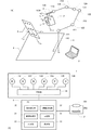
本発明の一実施例としてのロボットシステムは、図1に示すように、ロボット1と、カ
メラ2と、ロボット制御装置としてのPC(Personal Computer)3とを備えている。
Hereinafter, embodiments of the present invention will be described with reference to the accompanying drawings. In addition, the same code | symbol is attached | subjected to the corresponding component in each figure, and the overlapping description is abbreviate | omitted.
1. Configuration of Robot System As shown in FIG. 1, a robot system according to an embodiment of the present invention includes a
図1Aに簡略化して示すように、ロボット1は、6つの回転軸部材121、122、1
23、124、125、126によって屈曲するマニピュレーターを備える単腕6軸ロボ
ットである。基台110は、第一アーム111の回転軸部材121を支持している。第一
アーム111は回転軸部材121の中心軸を中心にして回転軸部材121とともに基台1
10に対して回転する。第一アーム111は、第二アーム112の回転軸部材122を支
持している。第二アーム112は、回転軸部材122の中心軸を中心にして回転軸部材1
22とともに第一アーム111に対して回転する。第二アーム112は、第三アーム11
3の回転軸部材123を支持している。第三アーム113は、回転軸部材123の中心軸
を中心にして回転軸部材123とともに第二アーム112に対して回転する。第三アーム
113は、第四アーム114の回転軸部材124を支持している。第四アーム114は、
回転軸部材124の中心軸を中心にして回転軸部材124とともに第三アーム113に対
して回転する。第四アーム114は、第五アーム115の回転軸部材125を支持してい
る。第五アーム115は、回転軸部材125の中心軸を中心にして回転軸部材125とと
もに第四アーム114に対して回転する。第五アーム115は、ツールが装着される回転
軸部材126を支持している。
As shown in a simplified manner in FIG. 1A, the
This is a single-arm six-axis robot provided with a manipulator that bends by means of 23, 124, 125, and 126. The
Rotate with respect to 10. The
22 and the
3 rotating
The
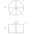
先端の回転軸部材126には、図2に示すように、ワークを操作するための各種のツー
ルが装着されるツールチャック1261が設けられている。図2Aに示すように、ツール
チャック1261の取付面は、放射状に分割されており、その中央部にツールの棒状の軸
部TJが装着される。ツールチャック1261は、回転軸部材126の回転軸上に各種の
ツールの軸部TJを挟み込んで保持する。したがってツールがツールチャック1261に
正しく装着された状態において、ツールの軸部TJの中心軸は、回転軸部材126の回転
軸と一致する。ここでロボット1を用いてワークを把持する際にロボット1とワークとの
接触点になる部分など、一般的には対象物に最も近い部分のロボット1側の基準点をツー
ルセンターポイント(TCP)という。本実施例においてTCPは制御対象点となる。
As shown in FIG. 2, a
図1Bに示すように、ロボット1は、回転軸部材121を駆動するモーター131と、
回転軸部材122を駆動するモーター132と、回転軸部材123を駆動するモーター1
33と、回転軸部材124を駆動するモーター134と、回転軸部材125を駆動するモ
ーター135と、回転軸部材126を駆動するモーター136と、モーター131〜13
6を制御する制御部14とを備えている。モーター131〜136は、目標値と現在値と
の差分がゼロになるようにフィードバック制御されるサーボモーターである。制御部14
は、TCPの位置と姿勢を示す目標値やJOG送り指示をPC3から取得し、目標値とJ
OG送り指示に基づいてモーター131〜136を制御する。
As shown in FIG. 1B, the
A
33, a
6 is provided. The
Obtains a target value and a JOG feed instruction indicating the position and orientation of the TCP from the
The
ロボット1を制御する際には、全ての座標系の基準となる基準座標系Rbの他に、各回
転軸部材に対して固定され各回転軸部材とともに回転する座標系J1〜J6と、特定のワ
ークをロボットビジョンを用いて処理する際に用いられるローカル座標系Lcが用いられ
る。これらの座標系の長さの単位はミリメートル、角度の単位は度である。ロボット1の
基準座標系Rbは、それぞれが水平なx0軸とy0軸と、鉛直下向きを正方向とするz0
軸とによって定まる3次元の直交座標系であって、ロボット1が設置されることによって
ロボット1が動作する空間に固定される。回転軸部材126とともに回転する座標系J6
は、TCPを原点とし、回転軸部材126の回転軸と平行なz6軸と、z6軸に対してそ
れぞれが垂直なx6軸とy6軸とによって定まる3次元の直交座標系である。なお、各座
標系のz軸周りの回転をu、y軸周りの回転をv、x軸周りの回転をwで表す。
When the
It is a three-dimensional orthogonal coordinate system determined by an axis, and is fixed in a space in which the
Is a three-dimensional orthogonal coordinate system that is determined by a z 6 axis parallel to the rotation axis of the
ツールチャック1261には、カメラ2と任意のツールとを取り付けるための延長チャ
ックTが固定される。撮像部としてのカメラ2は、その光軸Lが回転軸部材126の回転
軸と平行になるように延長チャックTに固定されている。カメラ2は、レンズ201、エ
リアイメージセンサー202、図示しないAD変換器等を備え、作業平面内におけるワー
クの大きさ、形状、位置、姿勢を認識するための撮像装置である。なお、本実施例で校正
されるロボットビジョンは、予め決められた作業平面を対象とする二次元のロボットビジ
ョンである。このため、レンズ201には、被写界深度が浅く(焦点距離が長く)F値が
小さな単焦点レンズを用いることが好ましい。
An extension chuck T for attaching the
カメラ2の位置と姿勢を定義するためにカメラ座標系Camが定義される。カメラ座標
系Camは、図1Aに示すように、撮像位置を原点とし、光軸Lと対応するzcam軸と
、イメージセンサー202の水平方向と対応するxcam軸と、イメージセンサー202
の垂直方向に対応するycam軸とを有し、J6座標系に対して固定された3次元の直交
座標系である。撮像位置は、光軸Lとイメージセンサー202の交点とする。カメラ座標
系Camは、回転軸部材1261に固定されたJ6座標系における撮像位置(x6、y6
、z6)とJ6座標系におけるカメラ座標系Camの姿勢(u6,v6、w6)とを成分
とするカメラ設定によって定義される。カメラ座標系Camの姿勢は、J6座標系の各軸
を中心としてカメラ座標系Camが何度ずつ回転しているかを表している。
A camera coordinate system Cam is defined to define the position and orientation of the
A three-dimensional orthogonal coordinate system having a y cam axis corresponding to the vertical direction and fixed to the J6 coordinate system. The imaging position is the intersection of the optical axis L and the
, Z 6 ) and the camera coordinate system Cam orientation (u 6 , v 6 , w 6 ) in the J6 coordinate system. The posture of the camera coordinate system Cam represents how many times the camera coordinate system Cam rotates around each axis of the J6 coordinate system.
カメラ2から出力される画像の座標系を画像座標系Imという。画像座標系Imの長さ
の単位はピクセル、角度の単位は度である。画像座標系Imと基準座標系Rbとを対応付
けることによって、作業平面内においてワークの位置、姿勢、形状を画像認識することが
可能になる。したがって、カメラ2が出力する画像に基づいてワークの位置等を認識して
、認識結果に基づいてロボット1を制御するためには、画像座標系Imと基準座標系Rb
とを関係づける処理、すなわち校正が必要になる。画像座標系Imと基準座標系Rbとの
関係は、レンズ201の光学特性(焦点距離、歪みなど)とエリアイメージセンサー20
2の画素数と大きさとに応じて定まる。校正では、基準座標系Rbと画像座標系Imとの
非線形な対応関係を示す変換行列が求められる。
A coordinate system of an image output from the
Need to be processed, that is, proofreading. The relationship between the image coordinate system Im and the reference coordinate system Rb depends on the optical characteristics (focal length, distortion, etc.) of the
2 is determined according to the number of pixels and the size. In the calibration, a transformation matrix indicating a non-linear correspondence between the reference coordinate system Rb and the image coordinate system Im is obtained.
ところで、作業平面が水平でない場合、x0y0平面が水平な基準座標系Rbを介して
ロボット1を制御したり操作するよりも、作業平面と平行な2軸を有する座標系を介して
ロボット1を制御したり操作する方が容易である。そこで本実施例では、水平面と任意の
角度をなす作業平面と平行な2軸を有するローカル座標系Lcを次のように定義する。
By the way, when the work plane is not horizontal, the robot through the coordinate system having two axes parallel to the work plane, rather than controlling or operating the
ローカル座標系Lcは、ロボットビジョンの視点(撮像位置)を原点とし、作業平面に
対して垂直でかつカメラ2の光軸Lと平行なzLc軸と、作業平面に対して平行でカメラ
2の光軸Lと垂直で画像座標系の水平軸と平行なxLc軸と、作業平面に対して平行でカ
メラ2の光軸Lと垂直で画像座標系の垂直軸と平行なyLc軸とを有し、基準座標系Rb
に対して固定された3次元の直交座標系である。すなわち、ローカル座標系Lcは、基準
座標系Rbで表される撮像位置と撮像姿勢とカメラ設定とによって、作業平面に対して都
度設定される。したがってカメラ設定が正確でなければ、ローカル座標系Lcを定義通り
に設定することができず、ローカル座標系Lcを介して意図通りにロボット1を制御する
ことができない。カメラ設定には、カメラ2の位置と姿勢の他、レンズ201の焦点距離
、主点、歪み等、レンズ201の光学特性に基づく情報が含まれる。焦点距離、主点、歪
み等はカメラ2にとって不変であるため、これらのレンズ201の光学特性に基づくカメ
ラ設定は、予め決められた値が用いられる。
The local coordinate system Lc has a robot vision viewpoint (imaging position) as an origin, a z Lc axis perpendicular to the work plane and parallel to the optical axis L of the
Is a three-dimensional orthogonal coordinate system fixed to That is, the local coordinate system Lc is set each time with respect to the work plane by the imaging position, the imaging attitude, and the camera setting represented by the reference coordinate system Rb. Therefore, if the camera settings are not accurate, the local coordinate system Lc cannot be set as defined, and the
ロボット制御装置としてのPC3はロボット1とカメラ2に通信可能に接続されている
。PC3には、ローカル座標系Lcを設定して基準座標系Rbと画像座標系Imとを校正
するための校正プログラムや、TCPに対するカメラ2とツールのオフセットを設定する
ためのツールセットプログラムや、教示プログラムなどの各種のコンピュータープログラ
ムがインストールされている。PC3は、図示しないプロセッサ、DRAMからなる図示
しない主記憶、図示しない入出力機構、不揮発性メモリからなる図示しない外部記憶、キ
ーボード等を備えるコンピューターである。またPC3は、カメラ2で撮像した画像やG
UIを表示するための画面を有する表示部35を備えている。PC3は、外部記憶に記憶
されたプログラムをプロセッサで実行することにより、指示受付部30、画像取得部31
、目標値導出部32、出力部33、校正部34として機能する。
A
A
, Function as a target
指示受付部30は、カメラ2によって撮像された画像やGUIを表示部35の画面に表
示する。また指示受付部30は各種の処理の開始指示を受け付けたり、目標位置や目標姿
勢といった制御パラメーターを、GUIを介して取得する。すなわち指示受付部は、制御
パラメーター取得部として機能する。
The
画像取得部31は、カメラ2に対して撮像を指示し、作業平面に含まれる基準点を示す
マーカーが指示に応じて撮像された画像をカメラ2から取得する。本実施例では、作業平
面を可視化するために図1Aおよび図3に示すマーカーボード4を用いる。図3に示すよ
うに、マーカーボード4は、円形の輪郭を有する9つのマーカー41〜49が平坦な面の
所定の格子点に付された板である。各マーカー41〜49の中心が基準点に相当する。マ
ーカーボード4上の各マーカー41〜49の中心位置はマーカーボード4に固定された2
次元の座標系(マーカー座標系Cb)でPC3が保持する。なお、マーカーはマーカーが
撮像された画像からマーカーを検出することにより基準点を特定可能な形態であればよい
。すなわち、特定の点の位置をマーカーの図形に対して幾何学的に定義できる形態であれ
ばよい。マーカーから離れた点が基準点として定義されてもよいし、1つのマーカーから
複数の基準点が定義されても良いし、互いに離れた複数のマーカーで1つの基準点が定義
されても良い。またマーカーによって平面を特定できればよいため、マーカーが指し示す
基準点の数は3以上であればよい。
The
PC3 holds in a dimensional coordinate system (marker coordinate system Cb). The marker may be in any form that can identify the reference point by detecting the marker from the image of the marker. In other words, any form can be used as long as the position of a specific point can be geometrically defined with respect to the marker figure. A point separated from the marker may be defined as a reference point, a plurality of reference points may be defined from one marker, or a single reference point may be defined by a plurality of markers separated from each other. Further, since it is sufficient that the plane can be specified by the marker, the number of reference points indicated by the marker may be three or more.
目標値導出部32は、カメラ2とマーカー41〜49の位置関係を予め決められた状態
に変化させるための目標値を、カメラ2が撮像した画像に基づいて導出する。具体的には
、目標値導出部32は、カメラ2が撮像した画像に基づいて、予め決められた状態に対応
するTCPの目標値を導出する。目標値導出部32は、目標値を導出する過程において、
画像座標系Imからローカル座標系Lcへの座標変換や、ローカル座標系Lcから基準座
標系Rbへの座標変換を実行する。また目標値導出部32は、基準座標系Rbとローカル
座標系Lcの対応関係を定める変換行列RbRLcを、カメラ2によって撮像された画像
とTCPの位置と姿勢とカメラ設定とに基づいて導出することによりローカル座標系Lc
を設定する。すなわち目標値導出部32はローカル座標系導出部として機能する。
The target
Coordinate conversion from the image coordinate system Im to the local coordinate system Lc and coordinate conversion from the local coordinate system Lc to the reference coordinate system Rb are executed. The target
Set. That is, the target
校正部34は、画像座標系Imと基準座標系Rbの対応関係を定める変換行列ImRR
bを導出する。校正部34は、それぞれに対応する目標値を目標値導出部32が導出する
以下の垂直状態と合焦状態にカメラ2とマーカー41〜49(基準点P1〜P9)の位置
関係が定められた後に、変換行列ImRRbを導出する。
・垂直状態:マーカーボード4とカメラ2の光軸が垂直な状態
・合焦状態:マーカーボード4にカメラ2が合焦する状態
The
b is derived. In the
・ Vertical state: The optical axis of the
合焦状態は、合焦の指標である画像のシャープネスによって定まる。なお、本実施例で
は、画像の予め決められた領域(部分画像)のシャープネスが最大になる状態を合焦状態
とするが、合焦の指標に閾値を設けることにより合焦状態に何らかの幅を持たせても良い
。
The in-focus state is determined by the sharpness of the image, which is an in-focus index. In this embodiment, the state where the sharpness of a predetermined region (partial image) of the image is maximized is set to the in-focus state. However, by providing a threshold for the in-focus index, a certain range is set in the in-focus state. You may have it.
出力部33は、目標値導出部32によって導出された目標値をロボット1の制御部14
に出力することにより、ロボット1を動作させる。
The
To output the
2.自動カメラ設定
次に自動カメラ設定について図4を参照しながら説明する。自動カメラ設定は、カメラ
設定としての撮像位置と撮像姿勢を自動的に設定する処理である。自動カメラ設定は、オ
ペレーターが開始指示をPC3に入力することによって起動する。それ以後、オペレータ
ーに一切の操作を要求することなく完了してもよい。開始指示は、自動カメラ設定を開始
するためのトリガーである。従って、ロボット1を操作するための目標値を含んでいなく
てもよい。開始指示を入力する前にオペレーターに求められるのは、マーカーボード4を
任意の位置と姿勢に設置することと、カメラ2によってマーカーボード4をだいたい正面
から撮像できる状態にTCPを移動させるジョグ送り操作だけであってもよい。
2. Automatic Camera Setting Next, automatic camera setting will be described with reference to FIG. The automatic camera setting is a process for automatically setting an imaging position and an imaging posture as camera settings. The automatic camera setting is activated when the operator inputs a start instruction to the
開始指示がPC3に入力されると(S1)、PC3は、画像に基づいてカメラ2の光軸
Lをマーカーボード4に対して垂直にする光軸傾き補正を実行する(S2)。傾き補正で
は、カメラ2によるマーカーボード4の撮像が行われ、9つの基準点を示すマーカー41
〜49が画像座標系Imで検出される。そして、検出結果に基づいて、マーカーボード4
とカメラ2の光軸が垂直になり中央のマーカー45を画像の重心に位置づけるための目標
値が導出されてアーム111〜115が動く。この時点では、カメラ2の焦点がマーカー
ボード4に合っていないため、マーカーボード4とカメラ2の光軸Lが凡そ垂直でマーカ
ー45の重心と画像の重心がほぼ一致する低精度垂直状態になる。詳細は後述する。
When a start instruction is input to the PC 3 (S1), the
˜49 are detected in the image coordinate system Im. Based on the detection result, the
Then, the optical axis of the
低精度垂直状態になると、PC3はローカル座標系Lcの仮設定を実行する(S3)。
具体的には回転軸部材121〜125の回転角度とカメラ設定とに基づいて暫定的な変換
行列RbRLcが導出される。低精度垂直状態は、カメラ2によって撮像された画像に基
づいて設定されるが、画像座標系Imと基準座標系Rbとの校正が完了しておらず、カメ
ラ設定も補正されていないこの段階では、回転軸部材121〜125の回転角度とカメラ
設定とに基づいて設定するローカル座標系LcのzLc軸はカメラ2の光軸Lと平行にな
らず、ローカル座標系LcのxLc軸はイメージセンサー202の水平方向と平行になら
ず、ローカル座標系LcのyLc軸はイメージセンサー202の垂直方向と平行にならな
い。
When the low-precision vertical state is reached, the
Specifically, a provisional conversion matrix Rb R Lc is derived based on the rotation angle of the
次にPC3は、焦点調整を実行する(S4)。焦点調整では、ローカル座標系Lcのz
Lc軸と平行な方向にカメラ2を移動させながらカメラ2によるマーカーボード4の撮像
が繰り返し行われ、画像に写るマーカー41〜49のシャープネスが最大になる合焦状態
が探索される。さらにPC3は、探索結果に基づいて合焦状態にするための目標値を導出
し、導出した目標値をロボット1に出力し、アーム111〜115を動かして合焦状態に
する。詳細は後述する。
Next, the
While the
次にPC3は、ローカル座標系LcのzLc軸方向とカメラ2の光軸Lとが平行になる
ように、カメラ2によって撮像された画像に基づいて、カメラ設定のv成分(y6軸周り
の回転成分)及びw成分(x6軸周りの回転成分)を補正するとともに、ローカル座標系
Lcを更新する(S5)。詳細には次の通りである。
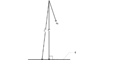
Next, the
基準座標系Rbにおいて光軸Lの方向を示すzLc軸の方向は、カメラ設定の撮像姿勢
(u,v,w)と回転軸部材121〜126の回転角度とに一意に関連づけられているた
め、カメラ設定として記憶されているカメラ2の撮像姿勢と、第五アーム115に取り付
けられているカメラ2の実際の撮像姿勢とが異なっている場合には、ローカル座標系Lc
のzLc軸方向が実際の光軸Lの方向からずれる。例えばカメラ設定の撮像姿勢が正確で
ない場合、図9に示すように、ロボットビジョンを用いて光軸Lがマーカーボード4に対
して垂直になる状態のTCPの姿勢(z6軸の方向)とカメラ設定の撮像姿勢とから導か
れるローカル座標系LcのzLc軸方向はマーカーボード4と垂直にならない。マーカー
ボード4に対して垂直でないローカル座標系LcのzLc軸方向にカメラ2を動かせば、
画像の重心に位置するマーカー45も画像座標系Imにおいて動く。
In the reference coordinate system Rb, the z Lc axis direction indicating the direction of the optical axis L is uniquely associated with the imaging posture (u, v, w) set by the camera and the rotation angles of the
The z Lc- axis direction is deviated from the actual optical axis L direction. For example, when the imaging posture set by the camera is not accurate, as shown in FIG. 9, the TCP posture (direction of the six axes) and the camera in a state where the optical axis L is perpendicular to the
The
そこでまずPC3は、ローカル座標系LcのzLc軸の方向にカメラ2を動かす前後に
おいてカメラ2によって撮像したそれぞれの画像から中央のマーカー45の中心位置を画
像座標系Imで検出する。そしてPC3は、zLc軸の方向にカメラ2を動かす前にカメ
ラ2によって撮像した画像から検出したマーカー45の中心座標を(u1,v1)とし、
zLc軸の方向にカメラ2を動かした後にカメラ2によって撮像した画像から検出したマ
ーカー45の中心座標を(u2,v2)として、次式(1)、(2)で定める傾き指標H
x、Hyを導出する。
Hx=(u1−u2)…(1)
Hy=(v1−v2)…(2)
Therefore, first, the
An inclination index H defined by the following equations (1) and (2), where (u 2 , v 2 ) is the center coordinate of the
x and Hy are derived.
H x = (u 1 −u 2 ) (1)
H y = (v 1 −v 2 ) (2)
続いてPC3は、傾き指標Hx、Hyに基づいて、TCPに固定されたx6軸とy6軸
を回転軸とする回転成分w、vについてカメラ設定の撮像姿勢を補正するとともに、補正
されたカメラ設定の撮像姿勢と回転軸部材121〜126の回転角度に基づいてローカル
座標系Lcを更新する。光軸の傾き補正が実行されると、ローカル座標系LcのzLc軸
は光軸Lと平行になる。
Subsequently, the
光軸の傾き補正において、カメラ設定の撮像姿勢を予め決められた角度だけ補正すると
ともにカメラ2を予め決められた角度だけ回転させる度に傾き指標Hx,Hyを導出し、
導出した傾き指標Hx、Hyを予め決められた既定値と比較する処理を、傾き指標Hx、
Hyが規定値未満になるまで繰り返してもよい。すなわち、カメラ2を動かしながら、カ
メラ設定の撮像姿勢とローカル座標系Lcを徐々に補正しても良い。また、zLc軸が光
軸と平行になる補正量を傾き指標Hx、Hyに基づいて算出しても良い。
In the tilt correction of the optical axis, the camera-set imaging posture is corrected by a predetermined angle and the tilt index Hx, Hy is derived each time the
A process of comparing the derived inclination indices H x , H y with a predetermined default value is performed as an inclination index H x ,
It may be repeated until the H y is less than the specified value. That is, the camera setting imaging posture and the local coordinate system Lc may be gradually corrected while moving the
次にPC3は、ローカル座標系LcのxLc軸方向にTCPを移動させることによって
画像の重心に位置するマーカー45が画像座標系Imの水平方向にのみ動くように、カメ
ラ設定の撮像姿勢を、J6座標系のz6軸を回転軸とする回転成分uについて補正する(
S6)。詳細には次の通りである。
Next, the
S6). Details are as follows.
まずPC3は、カメラ2によって撮像された画像に基づいて、カメラ2の光軸Lがマー
カーボード4と垂直でカメラ2から取得する画像の重心(u3,v3)に中央のマーカー
45が位置するようにカメラ2を移動させる。具体的には、ステップS5で更新されたロ
ーカル座標系LcのzLc軸とカメラ座標系Camのzcam軸とを平行に保った状態で
、カメラ2によって撮像された画像に基づいて、マーカー45の中心が画像の重心に位置
するようにカメラ2を移動させる。続いてPC3は、ステップS5で更新されたローカル
座標系LcのxLc軸方向にカメラ2をΔxだけ移動させる。続いてPC3は、カメラ2
から画像を取得し、取得した画像からマーカー45の中心位置(u4,v4)を検出する
。ローカル座標系LcのxLc軸がカメラ座標系Camのxcam軸と平行に設定されて
いれば、カメラ2がxLc軸方向に移動しても、画像座標系Imにおいてマーカー45は
垂直方向に移動しない。しかし、ローカル座標系LcのxLc軸がカメラ座標系Camの
xcam軸と平行に設定されていなければ、TCPがxLc軸方向に移動すると、画像座
標系Imにおいてマーカー45は、図10に示すように画像の重心から垂直方向に移動す
る。そこでローカル座標系LcのxLc軸とyLc軸とを、zLc軸を中心として回転さ
せる補正角度Δθを次式(3)で導出し、ローカル座標系LcのxLc軸とyLc軸の方
向とカメラ設定の回転成分uとを補正する。
![]()
From the acquired image, and the center position (u 4 , v 4 ) of the
![]()
次にPC3は、ローカル座標系LcのzLc軸と平行な軸周りにカメラ2を回転させる
ことによって画像の重心に位置するマーカー45が画像座標系Imにおいて動かないよう
にカメラ設定のx6成分及びy6成分を補正するとともに、ローカル座標系Lcを更新す
る(S7)。
Then PC3 is, x 6 components of camera settings so that the
ここでステップS7の処理を図11に基づいて詳細に説明する。まずPC3は、カメラ
2によって撮像された画像に基づいて、カメラ2の光軸Lがマーカーボード4と垂直でカ
メラ2から取得する画像の重心に中央のマーカー45が位置する初期状態にカメラ2を移
動させる(S71)。具体的には、ステップS6で更新されたローカル座標系LcのzL
c軸とカメラ座標系Camのzcam軸とが平行になり、マーカー45の中心が画像の重
心に位置するようにカメラ2を移動させる。
Here, the process of step S7 will be described in detail with reference to FIG. First, based on the image captured by the
The
続いてPC3は基準座標系Rbにおけるローカル座標系Lcの原点の座標を移動後のT
CPの位置とカメラ設定に基づいて更新する(S72)。この時点において、カメラ設定
のxy成分は補正されていないため、実際のカメラ2の撮像位置とは異なる座標にローカ
ル座標系Lcの原点が設定される。
Subsequently, the
Update based on the position of the CP and the camera setting (S72). At this time, since the xy component of the camera setting is not corrected, the origin of the local coordinate system Lc is set at coordinates different from the actual imaging position of the
続いてPC3は、ローカル座標系LcのzLc軸を回転軸としてカメラ2を規定角度θ
(例えば30度)だけ回転させる(S73)。ローカル座標系Lcの原点は実際のカメラ
2の撮像位置とは異なっているため、マーカー45の中心を通らない回転軸の周りをカメ
ラ2が回転することになる。
Subsequently, the
It is rotated by (for example, 30 degrees) (S73). Since the origin of the local coordinate system Lc is different from the actual imaging position of the
続いてPC3は、回転後のカメラ2から画像を取得し、取得した画像から中央のマーカ
ー45の中心位置を検出する(S74)。回転軸がマーカー45の中心を通っていないた
め、回転後のマーカー45の中心位置は回転前とは異なった位置で検出される。
Subsequently, the
続いてPC3は、規定回数だけステップS73でカメラ2を回転させたか否か判定する
(S75)。規定回数だけステップS73でカメラ2を回転させていなければ、PC3は
ステップS73から処理を繰り返す。ステップS73、74の処理が繰り返されると、マ
ーカー45の中心の軌跡は図12に示すように円弧を描く。
Subsequently, the
規定回数だけステップS73でカメラ2を回転させていれば、PC3はマーカー45の
中心が描いた円弧の中心O(u7,v7)を画像座標系Imで導出する(S76)。
If the
続いてPC3は、画像座標系Imで導出した円弧の中心Oに対応する点がローカル座標
系Lcの原点となるように基準座標系Rbにおいてローカル座標系LCをxLcyLc平
面と平行に移動させて更新するとともに、更新されたローカル座標系Lcと基準座標系R
bの対応関係に基づいてカメラ設定のx6成分及びy6成分を補正する(S77)。ロー
カル座標系が確定しておらず画像座標系Imと基準座標系Rbが校正されていないこの段
階では、ローカル座標系Lcまたは基準座標系Rbと画像座標系Imとの対応関係は定ま
っていない。そこでPC3は、ステップS76で求めた円弧の中心Oにマーカー45が位
置するようにカメラ2を並進させ、座像座標系Imにおいて検出するマーカー45の移動
前後の座標と、基準座標系Rbの移動前後の撮像位置(TCPとカメラ設定によって定ま
る撮像位置)とに基づいて画像座標系ImとステップS72で設定したローカル座標系L
cとの対応関係を導出する。続いてPC3は、導出した対応関係に基づいて画像座標系I
mにおける円弧の中心Oの座標をステップS72で設定したローカル座標系Lcの座標に
変換する。続いてPC3は、ステップS72で設定したローカル座標系Lcにおける円弧
の中心Oの座標を基準座標系Rbに変換し、円弧の中心Oを原点とする新たなローカル座
標系Lcを導出する。その結果、ステップS72で設定したローカル座標系LCはxLc
yLc平面と平行に移動する。また基準座標系Rbに変換された円弧の中心Oのxrb、
yrb座標は、実際のカメラ2の撮像位置のxrb、yrb座標と一致する。そこでPC
3は、円弧の中心Oのxrb、yrb座標とTCPの位置座標とに基づいてカメラ設定の
x6成分及びy6成分を補正する。
Subsequently, the
correcting the x 6 component and y 6 components of camera settings based on the corresponding relationship b (S77). At this stage where the local coordinate system is not determined and the image coordinate system Im and the reference coordinate system Rb are not calibrated, the correspondence between the local coordinate system Lc or the reference coordinate system Rb and the image coordinate system Im is not determined. Therefore, the
The correspondence relationship with c is derived. Subsequently, the
The coordinates of the center O of the arc at m are converted to the coordinates of the local coordinate system Lc set at step S72. Subsequently, the
y Move parallel to the Lc plane. X rb of the center O of the arc converted to the reference coordinate system Rb,
y rb coordinates, the actual imaging position of the
3, the center of the arc O of x rb, to correct the x 6 component and y 6 components of the camera set based on the position coordinates of the y rb coordinates and TCP.
次にPC3は、カメラ2によって撮像された画像に基づいて、カメラ設定のz6成分を
補正するとともに、ローカル座標系Lcを更新する(S8)。詳細は次の通りである。
Then PC3, based on the image captured by the
まずPC3は、カメラ2によって撮像された画像に基づいて、カメラ2の光軸Lがマー
カーボード4と垂直でカメラ2から取得する画像の重心に中央のマーカー45が位置する
初期状態にカメラ2を移動させる。具体的には、ステップS7で更新されたローカル座標
系LcのzLc軸とカメラ座標系Camのzcam軸とが平行になり、マーカー45の中
心が画像の重心に位置するようにカメラ2を移動させる。
First, based on the image captured by the
続いてPC3は、基準座標系Rbにおけるローカル座標系Lcの原点の座標を移動後の
TCPの位置とカメラ設定に基づいて更新する。この時点において、カメラ設定のz6成
分は補正されていないため、実際のカメラ2の撮像位置とは異なる座標にローカル座標系
Lcの原点が設定される。
Subsequently, the
続いてPC3は、初期状態でカメラ2から画像を取得してマーカー41〜49の位置を
画像座標系Imで検出し、検出したマーカー41〜49の位置とマーカー座標系Cbにお
けるマーカー41〜49の位置とに基づいてマーカーボード4から撮像位置までの距離H
を導出する。ここで画像座標系Imにおける距離とマーカー座標系Cbにおける距離との
関係は、マーカーボード4から撮像位置までの距離Hと線形に対応する。したがってPC
3は、画像座標系Imにおけるマーカー41〜49の位置から算定されるマーカー間距離
と、マーカー座標系Cbにおけるマーカー41〜49の位置から算定されるマーカー間距
離とにもとづいて距離Hを導出する。
Subsequently, the
Is derived. Here, the relationship between the distance in the image coordinate system Im and the distance in the marker coordinate system Cb corresponds linearly to the distance H from the
3 derives the distance H based on the inter-marker distance calculated from the positions of the
続いてPC3は、図13に示すように、撮像位置を変えずにカメラ2をxcam軸また
はycam軸の周りに規定角度θだけ回転させた後に、カメラ2から画像を取得してマー
カー45の中心位置を検出しながら、再びマーカー45が画像の重心に位置するまでカメ
ラ2をローカル座標系LcのxLcyLc平面に対して平行に移動させ、TCPの移動距
離ΔDを計測する。なお、この時点においてカメラ座標系Camのxcam軸はローカル
座標系LcのxLc軸と平行で、カメラ座標系Camのycam軸はローカル座標系Lc
のyLc軸と平行である。
Subsequently, as shown in FIG. 13, the
In parallel with the y Lc axis.
カメラ設定のz6成分が実際の撮像位置に対して正確に設定されていれば、計測される
TCPの移動距離とカメラ設定から導出されるカメラ2の移動距離ΔDと実際のカメラ2
の移動距離ΔD'とは等しくなる。しかしこの時点においては、カメラ設定のz6成分が
実際の撮像位置に対して正確に設定されていないため、TCPの位置とカメラ設定から導
かれる撮像位置は実際の撮像位置からzLc方向(マーカーボード4に対して垂直な方向
)にずれている。このため、図13に示すように実際のカメラ2の移動距離ΔD'とTC
Pの位置とカメラ設定から導かれる移動距離ΔDとは等しくならない。距離Hと角度θと
距離ΔDとカメラ設定のz6成分の誤差Δzの関係は、次式(4)によって表される。
(H+Δz)tanθ=ΔD…(4)
If the z 6 component of the camera setting is accurately set with respect to the actual imaging position, the measured moving distance of TCP, the moving distance ΔD of the
Is equal to the moving distance ΔD ′. However, in this time, since the z 6 components of the camera settings are not set correctly for the actual imaging position, z Lc direction (marker from the imaging position actual imaging position derived from the position and the camera settings TCP The direction is perpendicular to the
The position of P and the moving distance ΔD derived from the camera settings are not equal. The relationship between the distance H, the angle θ, the distance ΔD, and the camera setting z 6 component error Δz is expressed by the following equation (4).
(H + Δz) tan θ = ΔD (4)
そこでPC3は、次式(5)によってΔzを導出してカメラ設定のz6成分を補正して
確定させるとともに、回転軸部材121〜126の回転角度から導かれる現在のTCPの
位置と補正後のカメラ設定とに基づいてローカル座標系Lcを更新する。
![]()
![]()
更新されたローカル座標系Lcは、実際のカメラ2の撮像位置を原点とし、カメラ2の
光軸Lと平行なzLc軸と、イメージセンサー202の水平方向と平行なxLc軸とし、
イメージセンサー202の垂直方向と平行なyLc軸とを有する座標系になる。また確定
したカメラ設定は、カメラ2の撮像位置と撮像姿勢と正確に対応する。
The updated local coordinate system Lc has an actual imaging position of the
The coordinate system has a y Lc axis parallel to the vertical direction of the
3.光軸傾き補正
次に図5を参照しながら光軸傾き補正の詳細を説明する。光軸傾き補正では、姿勢と位
置が未知のマーカーボード4を基準として実際のカメラ2の撮像位置と撮像方向が補正さ
れる。具体的には、マーカーボード4に固定された座標系Cbに対するカメラ2の撮像位
置と撮像姿勢を導出し、マーカー座標系Cbのzcb軸がカメラ2の光軸Lと平行になる
ようにカメラ2の姿勢を変化させる。
3. Optical Axis Inclination Correction Next, details of the optical axis inclination correction will be described with reference to FIG. In the optical axis tilt correction, the actual imaging position and imaging direction of the
まず目標値導出部32は、画像取得部31を介してカメラ2から画像を取得し、画像を
解析することによりマーカー41〜49の中心位置を検出する(S21)。すなわち、目
標値導出部32は、作業平面に含まれる9つの基準点の位置を画像座標系において検出す
る。
First, the target
続いて目標値導出部32は、マーカー座標系Cbにおいて予め決められているマーカー
ボード4上の各マーカー41〜49の中心位置と、画像座標系Imにおいて検出したマー
カー41〜49の中心位置とに基づいて、マーカー座標系Cbにおけるカメラ2の姿勢を
示す姿勢行列Cを導出する(S22)。式(6)に示す姿勢行列Cにおいて、(a11,
a21,a31)はマーカー座標系CbにおけるxCam軸の方向を表すベクトルCxで
あり、(a12,a22,a32)はマーカー座標系CbにおけるyCam軸の方向を表
すベクトルCyであり、(a13,a23,a33)はマーカー座標系Cbにおける光軸
Lの方向を表すベクトルCzである。

a 21 , a 31 ) is a vector C x representing the direction of the x Cam axis in the marker coordinate system Cb, and (a 12 , a 22 , a 32 ) is a vector C representing the direction of the y Cam axis in the marker coordinate system Cb. y , (a 13 , a 23 , a 33 ) is a vector C z representing the direction of the optical axis L in the marker coordinate system Cb.
次に、目標値導出部32は、カメラ2の姿勢行列Cに基づいて、光軸Lの傾き指標θx
、θy、θzを導出する(S23)。θxは、xCam軸とxCb軸とがなす角度である
。θyは、yCam軸とyCb軸とがなす角度である。θzは、光軸LとzCb軸とがな
す角度である。マーカー座標系Cbにおいて、xcb軸の方向を示すベクトルXは(1,
0,0)、ycb軸の方向を示すベクトルYは(0,1,0)、zcb軸の方向を示すベ
クトルZは(0,0,1)である。
Cx・X=|Cx|cosθx=a11・・・(7)
Cy・Y=|Cy|cosθy=a22・・・(8)
Cz・Z=|Cz|cosθz=a33・・・(9)
であるから、目標値導出部32は、次式(10)、(11)、(12)を用いて傾き指
標θx、θy、θzを導出する
θx=acos(a11/|Cx|)・・・(10)
θy=acos(a22/|Cy|)・・・(11)
θz=acos(a33/|Cz|)・・・(12)
Next, the target
, Θ y , θ z are derived (S23). θ x is an angle formed by the x Cam axis and the x Cb axis. θ y is an angle formed by the y Cam axis and the y Cb axis. θ z is an angle formed by the optical axis L and the z Cb axis. In the marker coordinate system Cb, a vector X indicating the direction of the xcb axis is (1,
0,0), the vector Y indicating the direction of the y cb axis is (0,1,0), and the vector Z indicating the direction of the z cb axis is (0,0,1).
C x · X = | C x | cos θ x = a 11 (7)
C y · Y = | C y | cos θ y = a 22 (8)
C z · Z = | C z | cos θ z = a 33 (9)
Therefore, the target
θ y = acos (a 22 / | C y |) (11)
θ z = acos (a 33 / | C z |) (12)
続いて目標値導出部32は、傾き指標θx、θy、θzが全て規定値以下であるか否か
を判定する(ステップS24)。既定値は例えば0.5度とする。傾き指標θx、θy、
θzが全て規定値以下になると、光軸傾き補正を終了する。
Subsequently, the target
When all θz are equal to or less than the specified value, the optical axis tilt correction is terminated.
傾き指標θx、θy、θzが全て規定値以下でない場合、目標値導出部32は、ステッ
プS23で導出した傾き指標に基づいて、カメラ2の光軸Lに対してマーカーボード4が
垂直になり、かつ、光軸Lが中央のマーカー45の中心を通る位置と姿勢にカメラ2を動
かすための目標値を導出する。導出された目標値は、出力部33によってロボット1の制
御部14に出力される。その結果、アーム111〜115が動く(S25)。
When the tilt indices θ x , θ y , and θ z are not all equal to or less than the specified values, the target
目標値を出力部33がロボット1に出力してアーム111〜115が動いて停止すると
、画像取得部31がカメラ2から画像を取得し、画像に基づいて目標値導出部32が傾き
指標を導出して評価する上述のステップS21からステップS24の処理が繰り返される
。
When the
4.焦点調整
次に図6を参照しながら焦点調整の詳細を説明する。焦点調整では、図7に示すように
カメラ2の光軸Lと平行な方向にTCPを移動させながら画像に写るマーカー41〜49
のシャープネスが最大になる合焦状態が探索される。
4). Focus Adjustment Next, details of the focus adjustment will be described with reference to FIG. In the focus adjustment,
The in-focus state that maximizes the sharpness is searched.
はじめに目標値導出部32は現在のTCPの位置と姿勢を保存する(S31)。すなわ
ち、ステップS2の傾き補正が終了した時点におけるTCPの位置と姿勢が保存される。
First, the target
次に、目標値導出部32は、マーカー座標系Cbでのマーカー41〜49の各重心の座
標と、画像座標系でのマーカー41〜49の各重心の座標とに基づいて、カメラ2からマ
ーカーボード4までの距離とを導出する(S32)。
Next, the target
続いて目標値導出部32は、カメラ2から取得した画像に基づいてカメラ2の合焦指標
を導出する(S34)。合焦指標としては、マーカー41〜49が写る領域の微分積算値
(シャープネス)を一定面積で標準化した値を用いることができる。合焦指標を導出する
対象領域は、図8Aおよび図8Bの点線で囲んだ領域のように全てのマーカー41〜49
が内側に収まる最小の矩形領域に設定される。すなわち、カメラ2によってマーカー41
〜49が撮像された画像から切り出された部分画像に基づいて合焦指標が導出される。
Subsequently, the target
Is set to the smallest rectangular area that fits inside. That is, the
A focus index is derived based on the partial image cut out from the image obtained by capturing .about.49.
続いて目標値導出部32は、焦点調整においてカメラ2が撮像した回数が規定回数に達
したか否かを判定する(S35)。
Subsequently, the target
焦点調整においてカメラ2が撮像した回数が規定回数に達していない場合、目標値導出
部32はカメラ2の光軸Lと平行でマーカーボード4に接近または離間する方向に所定距
離だけTCPを移動させる(S36)。
When the number of times the
TCPを移動させると、画像取得部31はカメラ2から画像を取得し(S37)、ステ
ップS33から処理が繰り返される。すなわち、撮像回数が規定回数に達するまで、撮像
位置を変えながらカメラ2による撮像が行われ、撮像された画像毎に合焦指標が導出され
る。マーカーボード4に接近するほど、マーカー41〜49が写る領域は大きくなり、や
がてマーカー41〜49は図8Cに示すように画像に収まらなくなる。そこで合焦指標を
導出する対象領域は、カメラ2がマーカーボード4に接近するほど大きく設定され、マー
カー41〜49が写る領域が画像の端辺に接した後に画像全体になる。このようにして設
定される領域について合焦指標が導出されると、合焦指標がシャープネスであれば、通常
は、徐々に大きくなった後に徐々に小さくなる。
When the TCP is moved, the
焦点調整においてカメラ2が撮像した回数が規定回数に達すると、目標値導出部32は
、合焦状態にするための目標値を合焦指標に基づいて導出し、出力部33は導出された目
標値をロボット1に出力する(S38)。具体的には例えば、ステップS34で導出され
る複数の合焦指標のうち最大の合焦指標が得られた位置にTCPを移動させるための目標
値が導出される。導出された目標値がロボット1に出力されると、マーカーボード4はカ
メラ2に対して合焦状態になる。
When the number of times the
5.ローカル座標系の自動設定と自動校正
作業平面を示すローカル座標系を設定したり、基準座標系Rbと画像座標系Imとを校
正するためには、従来であれば、作業平面に対してカメラ2の光軸Lを正確に垂直な状態
にセットしたり、J6軸が作業平面に対して垂直な姿勢で作業平面をタッチアップして作
業平面の位置と姿勢を正確に教示したりといった緻密な準備が必要であった。作業平面が
水平でない場合には、作業平面をタッチアップする操作の難易度が上がる。そして、これ
らの準備が不正確である場合には校正が失敗する。またオペレーターは校正の失敗を知る
ことによって、校正の準備が不正確であったことを知る。したがって、従来は校正とロー
カル座標系の設定に多大な時間を要していた。
5. Automatic setting and automatic calibration of local coordinate system Conventionally, in order to set a local coordinate system indicating a work plane or to calibrate the reference coordinate system Rb and the image coordinate system Im, the
ローカル座標系の自動設定と自動校正では、校正が行われていない状態でのロボットビ
ジョン(カメラ2によって撮像される画像)を用いて校正とローカル座標系の設定を自動
で行う。自動で行われる校正の準備には、作業平面を示すマーカーボード4に対してカメ
ラ2の光軸が垂直であって、カメラ2がマーカーボード4に合焦している状態にする自動
制御を含む。このため、マーカーボード4とカメラ2との正確な位置関係が定まっていな
い状態で開始指示を入力するだけで、基準座標系Rbと画像座標系Imとを、極めて容易
に校正することができる。そして校正の準備が完了している状態で、ローカル座標系Lc
を設定することにより、作業平面を基準としてロボット1を制御することが容易になる。
In automatic setting and automatic calibration of the local coordinate system, calibration and setting of the local coordinate system are automatically performed using a robot vision (an image captured by the camera 2) in a state where calibration is not performed. The calibration preparation that is automatically performed includes automatic control in which the optical axis of the
It becomes easy to control the
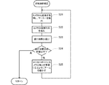
以下、ローカル座標系の自動設定と自動校正について図14を参照しながら説明する。
ローカル座標系の自動設定と自動校正は、オペレーターが開始指示をPC3に入力するこ
とによって起動する。(S11)それ以後、オペレーターに一切の操作を要求することな
く完了してもよい。開始指示は、ローカル座標系の自動設定と自動校正を開始するための
トリガーである。従って、ロボット1を操作するための目標値を含んでいなくてもよい。
開始指示を入力する前にオペレーターに求められるのは、カメラ設定をPC3に設定する
ことと、マーカーボード4を作業平面に設置することと、カメラ2によってマーカーボー
ド4をだいたい正面から撮像できる状態にTCPを移動させるジョグ送り操作だけであっ
てもよい。
Hereinafter, automatic setting and automatic calibration of the local coordinate system will be described with reference to FIG.
Automatic setting and automatic calibration of the local coordinate system are started when the operator inputs a start instruction to the
Before inputting the start instruction, the operator is required to set the camera setting to PC3, to install the
開始指示がPC3に入力されると、PC3は、カメラ2の光軸Lをマーカーボード4に
対して垂直にする光軸傾き補正を実行する(S12)。次にPC3は、焦点調整を実行す
る(S14)。次にPC3は、再び光軸傾き補正を実行する。ここで実行される光軸傾き
補正および焦点調整は、自動カメラ設定において述べた光軸傾き補正(S2)および焦点
調整(S4)と同一である。2度目の光軸傾き補正が実行されると、カメラ2の光軸Lが
マーカーボード4に対して正確に垂直になる。
When the start instruction is input to the
次にPC3はローカル座標系の設定を実行する(S16)。詳細にはまずPC3は、カ
メラ2によって撮像された画像に基づいて、カメラ2の光軸Lがマーカーボード4と垂直
でカメラ2から取得する画像の重心に中央のマーカー45が位置するようにカメラ2を移
動させる。具体的には、光軸傾き補正が実行された状態から、マーカー45の中心が画像
の重心に位置するようにカメラ2の撮像位置を並進させる。続いてPC3は、TCPの位
置と姿勢とカメラ設定とに基づいてローカル座標系Lcを設定する。カメラ設定が正確で
あるため、実際のカメラ2の撮像位置を原点とし、マーカーボード4に対して垂直なzL
c軸と、イメージセンサー202の水平方向と平行なxLc軸と、イメージセンサー20
2の垂直方向と平行なyLc軸とを有するローカル座標系Lcが設定される。
Next, the
the c- axis, the x Lc- axis parallel to the horizontal direction of the
A local coordinate system Lc having two y Lc axes parallel to the vertical direction is set.
次にPC3は9点校正を実施する(ステップS17)。この時点においてローカル座標
系のxLcyLC平面はマーカーボード4に対して平行になっている。このことは、画像
から検出するマーカー41〜49の位置に基づいて、ローカル座標系Lcと作業平面を表
す画像座標系Imを校正できること、および基準座標系Rbと画像座標系Imを構成でき
ることを意味する。
Next, the
具体的には、校正部34は、ローカル座標系Lcが設定された状態(原点に撮像位置を
位置づけ、ローカル座標系とカメラ座標系のxyz軸をそれぞれ互いに平行にした状態)
でカメラ2から画像を取得して各マーカー41〜49の画像座標系Imにおける位置を検
出して記憶する。次に校正部34は、検出した各マーカー41〜49の中心座標を画像座
標系Imからローカル座標系Lcに変換し、各マーカー41〜49の中心が画像の重心に
位置するようにカメラ2の撮像位置を並進させる。続いて校正部34は、画像座標系Im
において検出した各マーカー41〜49の中心座標と、各マーカー41〜49の中心が画
像の重心に位置するカメラ2の撮像位置とに基づいて、ローカル座標系Lcと画像座標系
Imとを校正する。すなわち、ローカル座標系Lcと画像座標系Imとの非線形な対応関
係を示すパラメーターが、9つのマーカー41〜49からxLcyLC平面に下ろした垂
線とxLcyLC平面との交点を示すローカル座標系Lcの座標(撮像位置の座標)と、
中央のマーカー45が画像の重心に位置する画像座標系Imから検出される9つのマーカ
ー41〜49の中心座標とを用いて導出される。ここでは、作業平面上の任意の点につい
て、レンズ201の歪みも加味して、正確にローカル座標系Lcと画像座標系Imとを校
正する。なお、このような非線形変換に用いるパラメーターを導出するために用いる基準
点の数が多いほど校正の精度は高くなる。すなわち基準点を示すマーカーの数が多いほど
校正の精度は高くなる。ローカル座標系Lcと基準座標系Rbとの対応関係は既に決めら
れているため、基準座標系Rbと画像座標系Imとは、ローカル座標系Lcと画像座標系
Imとを校正する際に校正しても良いし、校正しなくても良い。またローカル座標系Lc
と画像座標系Imとを校正せずに、基準座標系Rbと画像座標系Imとを校正しても良い
。
Specifically, the
Then, an image is acquired from the
The local coordinate system Lc and the image coordinate system Im are calibrated based on the center coordinates of the
The
The reference coordinate system Rb and the image coordinate system Im may be calibrated without calibrating the image coordinate system Im.
6.目標設定
作業平面に対してローカル座標系Lcが設定され、ローカル座標系Lcまたは基準座標
系Rbと、画像座標系Imとが校正された状態では、作業平面が水平でなくても、作業平
面上の任意の点をロボット1に容易に教示することができる。以下、作業平面上の任意の
点をロボット1に教示する目標設定について図15を参照しながら説明する。作業平面に
対してローカル座標系Lcの自動設定と自動校正が実行された状態では、作業平面上の任
意の点と画像座標系Imの任意の点との対応関係が明らかになっているため、目標設定は
、作業平面からマーカーボード4を除去した状態で実行可能である。
6). Target setting In a state where the local coordinate system Lc is set for the work plane and the local coordinate system Lc or the reference coordinate system Rb and the image coordinate system Im are calibrated, even if the work plane is not horizontal, Any point can be easily taught to the
まずPC3は、作業平面の画像をカメラ2から取得して画面に表示する(S21)。具
体的には、PC3はローカル座標系Lcの原点に撮像位置を設定し、ローカル座標系Lc
のxLc軸、yLc軸、zLc軸がそれぞれカメラ座標系Camのxcam軸、ycam
軸、zcam軸と平行になる撮像姿勢を設定してカメラ2に撮像を指示することによって
カメラ2から画像を取得し、取得した画像を表示部35の画面に表示する。
First, the
XLc axis, yLc axis, and zLc axis are x cam axis and y cam of the camera coordinate system Cam, respectively.
An image is acquired from the
次にPC3は、TCPやツールの先端などの制御対象点を制御するための制御パラメー
ターを画像座標系Imを介して取得する(S22)。具体的には例えば指示受付部30(
制御パラメーター取得部)は、表示した画像の任意の点に対するクリック、タップ等の操
作を、制御対象点を移動させる目標点の位置の指定として受け付ける。すなわちPC3は
、制御パラメーターとしての目標点の座標を画像座標系Imを介して取得する。このとき
PC3は、目標点の指定と対応付けて目標姿勢の指定を受け付けても良い。例えば指定さ
れた目標点に対して、数値の直接入力やスライダーの操作等によって目標姿勢を指定でき
るようにしてもよい。目標姿勢は、制御対象点の姿勢を定める座標系の少なくとも1軸の
方向をローカル座標系Lcにおいて指定することによって指定可能である。そしてこのよ
うな目標姿勢の指定がなされない場合には、あらかじめ決められた姿勢を目標姿勢とみな
せばよい。例えば制御対象点がTCPに装着されるドリルビットの先端である場合、ドリ
ルビットの回転軸が作業平面に対して垂直になる姿勢、すなわちドリルビットの回転軸が
ローカル座標系LcのzLc軸に平行な姿勢を目標姿勢とみなせばよい。
Next, the
The control parameter acquisition unit) accepts an operation such as clicking or tapping on an arbitrary point of the displayed image as designation of the position of the target point for moving the control target point. That is, the
次にPC3は、目標点の座標をローカル座標系Lcに変換する(S23)。すなわちP
C3は、画面表示した画像内の任意の点がローカル座標系Lcの特定の点に対応するもの
としてステップS22において制御パラメーターを取得している。したがってここでロー
カル座標系Lcを介して制御パラメーターとしての目標点の位置と目標姿勢がPC3に取
得される。座標変換には、自動校正によって求められたパラメーターが用いられる。
Next, the
In C3, the control parameter is acquired in step S22 on the assumption that an arbitrary point in the image displayed on the screen corresponds to a specific point in the local coordinate system Lc. Therefore, the position of the target point and the target posture as control parameters are acquired by the
次にPC3は、ローカル座標系Lcに変換された制御パラメーターを用いて制御対象点
を制御する(S24)。このとき、制御パラメーターは、PC3によって、基準座標系R
bにおいて位置を示す座標と、基準座標系Rbにおいて姿勢を示す行列または角度とに変
換されてロボット1に出力された後に、ロボット1の制御部14によって回転軸部材12
1〜126を駆動するモーター131〜136の回転角度に変換される。制御部14は、
モーター131〜136を回転させることによってTCPを作業平面上の目標点に目標姿
勢で移動させる。
Next, the
After being converted into coordinates indicating the position in b and a matrix or angle indicating the posture in the reference coordinate system Rb and output to the
The rotation angles of the
By rotating the
なお、実際には、制御パラメーターの入力を受け付けた後に実行開始のコマンド入力を
ユーザーに求めるなど、制御パラメーターの入力操作が終了したことをPC3に通知する
必要がある。例えば、実行開始のボタンを画面表示しておき、当該ボタンがクリックされ
た場合に、ステップS23の処理を開始すればよい。なお、複数の目標点の設定を一度に
受け付けることも可能である。
In practice, it is necessary to notify the
制御対象点を移動させる場合に、始点から目標点までの経路をどのように定めても良い
が、例えば、作業平面に対して平行な方向への移動モードと、作業平面に対して垂直な方
向への移動モードを、モードの切換数が最小になるように組み合わせればよい。このよう
に作業平面に対して平行な方向への移動と、作業平面に対して垂直な方向への移動を組み
合わせて制御対象点を移動させる場合、ローカル座標系Lcを介して制御パラメーターを
取得するため、移動方向の計算アルゴリズムの設計が容易である。またこの場合、制御対
象点の移動経路をユーザーが容易に予測できる。
When moving the control target point, the path from the start point to the target point may be determined in any way. For example, the movement mode in a direction parallel to the work plane and the direction perpendicular to the work plane The movement modes to the above may be combined so that the number of mode switching is minimized. When the control point is moved by combining the movement in the direction parallel to the work plane and the movement in the direction perpendicular to the work plane in this way, the control parameter is acquired via the local coordinate system Lc. Therefore, it is easy to design a moving direction calculation algorithm. In this case, the user can easily predict the movement path of the control target point.
また、制御対象点がツールに設定されている場合、PC3は、ツールの先端等の制御対
象点の目標点と目標姿勢を、画像座標系Imを介して取得する。この場合、TCPに対す
るツールのオフセットを予め設定しておく必要がある。ツールの先端等の制御対象点を制
御するために、PC3は、ユーザーによって設定される制御対象点の目標点の座標を、オ
フセットを用いて基準座標系RbにおけるTCPの座標に変換し、ユーザーによって設定
される制御対象点の目標姿勢を、オフセットを用いて基準座標系RbにおけるTCPの目
標姿勢に変換する処理を実行してロボット1に出力する。ロボット1の制御部14は基準
座標系Rbの座標と姿勢行列または角度に基づいて、回転軸部材121〜126を駆動す
るモーター131〜136の回転角度を導出する。
When the control target point is set in the tool, the
以上述べた目標設定では、ユーザーは、作業平面が水平でなくても、画像内の点を指定
するだけで作業平面内の目標点を容易に指定することが可能である。そしてカメラ2が撮
像した画像によって作業平面が表されているため、ユーザーは現実の作業平面の任意の点
と画面表示された画像内の点とを容易に対応付けて認識することができる。
In the target setting described above, even if the work plane is not horizontal, the user can easily specify the target point in the work plane only by specifying a point in the image. Since the work plane is represented by the image captured by the
また目標姿勢の指定を受け付ける場合には、作業平面に対して平行なxLcyLc平面
を有するローカル座標系Lcを介して目標姿勢を取得するため、作業平面が水平でなくて
も、xLcyLc平面と平行な作業平面を垂直方向からカメラ2で撮像した画像を見なが
ら目標姿勢を指定するユーザーにとって、現実の作業平面に対する目標姿勢と対応付けて
容易に目標姿勢を指定することができる。
When the designation of the target posture is accepted, the target posture is acquired via the local coordinate system Lc having the x Lc y Lc plane parallel to the work plane. Therefore, even if the work plane is not horizontal, x Lc For a user who specifies a target posture while viewing an image obtained by capturing the work plane parallel to the y Lc plane from the vertical direction with the
7.他の実施形態
上記実施例では、カメラ2をロボット1のアームに取り付ける構成について説明した。
カメラ2をロボット1のアームに取り付ける構成では、作業平面に対する任意の位置にカ
メラ2を移動させてローカル座標系を設定し、設定したローカル座標系を基準にしてロボ
ット1を操作することができる。すなわち、カメラ2をロボット1のアームに取り付ける
構成では、作業平面に対して撮像位置毎にローカル座標系を設定することができる。
7). Other Embodiments In the above embodiment, the configuration in which the
In the configuration in which the
本発明は、カメラ2が作業台、壁、床、天井等に設置されるロボットシステムにも適用
できる。カメラ2が作業台、壁、床、天井等に設置される構成では、作業平面が設定され
てしまえば、カメラ2と作業平面の位置関係は不変になるため、作業平面に対してローカ
ル座標系が1つ設定される。
The present invention can also be applied to a robot system in which the
図16に示すようにカメラ2が作業台9に設置されている場合、マーカーボードを用い
ずに作業平面を設定し、設定した作業平面に対してローカル座標系を自動設定して自動校
正することもできる。以下、カメラ2が作業台9に設置される場合に、マーカーボードを
用いずに作業平面を設定し、ローカル座標系の自動設定と自動校正を実行する方法につい
て説明する。マーカーボードを用いない場合には、作業平面上の複数の基準点をロボット
1のマニピュレーターで指し示せばよい。具体的には、基準点を指し示すためのマーカー
としてツールチャック1261を用いる。このため、図2Aに示すツールチャック126
1の端面を画像認識するためのテンプレートをPC3に予め記憶しておく。
When the
A template for recognizing an image of one end face is stored in the
作業平面を設定するにあたり、PC3は、作業平面に対してJ6軸が垂直な姿勢で作業
平面上の複数の基準点のそれぞれにツールチャック1261のTCPを移動させる。ここ
では図17に示すように作業平面WSに対して基準点P1〜P9が設定されるものとする
。そして、PC3は、各基準点にTCPが位置する状態で撮像された画像をカメラ2から
取得し、画像座標系Imにおいて基準点P1〜P9の位置を検出する。
In setting the work plane, the
ここでカメラ2によって撮像される画像について図18を用いて説明する。9つの基準
点P1〜P9にマーカーとしてのTCPを移動させる毎にカメラ2によってツールチャッ
ク1261を撮像すると、カメラ2から取得する各画像におけるツールチャック1261
の位置は、基準点P1〜P9の位置に応じて異なることになる。基準座標系Rbで作業平
面内に設定された各基準点にTCPを動かして、それぞれの基準点におけるTCPを基準
座標系Rbにおいて固定されたカメラ2で撮像したn個の画像から得られる基準点の位置
情報は、n個の基準点を示すマーカーが付されているマーカーボードを特定の位置と姿勢
に保持し、その状態でマーカーを撮像した1つの画像から得られる基準点の情報とほぼ同
じである。前者の情報には、厳密な基準座標系と画像座標系の対応関係が反映され、後者
の情報には、基準座標系とマーカー座標系を合成した座標系と画像座標系の対応関係が反
映される。基準座標系とマーカー座標系が厳密な線形な関係にあるとは限らないため、厳
密に基準座標系と画像座標系を校正するには、前者の情報を用いることが好ましい。
Here, an image captured by the
Is different depending on the positions of the reference points P1 to P9. A reference point obtained from n images obtained by moving TCP to each reference point set in the work plane in the reference coordinate system Rb and capturing the TCP at each reference point with the
作業平面にマーカーボードを設置してマーカーの位置を画像座標系Imにおいて検出す
るかわりに、作業平面にマーカーを移動させて基準点P1〜P9の位置を画像座標系Im
において検出すれば、既に説明した自動カメラ設定、自動校正、目標設定のいずれも同様
に実施することができる。ただし、基準点によって作業平面を定めることになるため、作
業平面を示すローカル座標系Lcはカメラ2によって撮像する画像に基づいて設定するの
ではなく、予め決めておくことになる。したがってTCP等のマーカーを移動させる際に
は、予め決められたローカル座標系Lcを介してマーカーを制御することになる。
Instead of installing a marker board on the work plane and detecting the position of the marker in the image coordinate system Im, the marker is moved to the work plane and the positions of the reference points P1 to P9 are set in the image coordinate system Im.
If detected in step, any of the automatic camera setting, automatic calibration, and target setting already described can be performed in the same manner. However, since the work plane is determined by the reference point, the local coordinate system Lc indicating the work plane is not set based on the image captured by the
ここまでローカル座標系LcのxLcyLc平面上の点を作業平面上の点に対応付けて
きたが、ローカル座標系LcのxLcyLc平面上の点を作業平面と平行で作業平面から
離れた平面上の点に対応付けても良い。例えばこれまで説明したとおりにマーカーボード
を作業平面に設置してローカル座標系Lcを設定した後に、ローカル座標系Lcの原点を
zLc軸方向に移動させてローカル座標系Lcを更新しても良い。
Up to this point, the points on the xLc y Lc plane of the local coordinate system Lc have been associated with the points on the work plane, but the points on the x Lc y Lc plane of the local coordinate system Lc are parallel to the work plane and from the work plane. It may be associated with a point on a distant plane. For example, as described above, after setting the marker board on the work plane and setting the local coordinate system Lc, the local coordinate system Lc may be updated by moving the origin of the local coordinate system Lc in the zLc axis direction.
なお、作業面からローカル座標系LcのxLcyLc平面までの距離は、マーカー座標
系において間隔が既知の2つ以上のマーカーを画像座標系Imにおいて検出し、マーカー
座標系におけるマーカー同士の間隔と画像座標系Imにおけるマーカー同士の間隔とに基
づいて導出しても良いし、TCPやツールで作業平面をタッチアップする過程でTCPの
移動距離を計測して作業面からローカル座標系LcのxLcyLc平面までの距離を導出
しても良い。
The distance from the work plane to the x Lc y Lc plane of the local coordinate system Lc is determined by detecting two or more markers having a known interval in the marker coordinate system in the image coordinate system Im, and the interval between the markers in the marker coordinate system. And the distance between the markers in the image coordinate system Im, or the movement distance of the TCP is measured in the process of touching up the work plane with TCP or a tool, and the x of the local coordinate system Lc is measured from the work surface. The distance to the Lc y Lc plane may be derived.
41-49…マーカー、121-126…回転軸部材、131-136…モーター、111-
115…アーム、121-126…回転軸部材、1…ロボット、2…カメラ、3…PC、
4…マーカーボード、9…作業台、14…制御部、30…指示受付部、31…画像取得部
、32…目標値導出部、33…出力部、34…校正部、35…表示部、110…基台、1
11…第一アーム、112…第二アーム、113…第三アーム、114…第四アーム、1
15…第五アーム、201…レンズ、202…イメージセンサー、1261…ツールチャ
ック、L…光軸、T…ツール、TJ…軸部、WS…作業平面
41-49 ... marker, 121-126 ... rotating shaft member, 131-136 ... motor, 111-
115 ... Arm, 121-126 ... Rotating shaft member, 1 ... Robot, 2 ... Camera, 3 ... PC,
DESCRIPTION OF
11 ... 1st arm, 112 ... 2nd arm, 113 ... 3rd arm, 114 ... 4th arm, 1
DESCRIPTION OF SYMBOLS 15 ... 5th arm, 201 ... Lens, 202 ... Image sensor, 1261 ... Tool chuck, L ... Optical axis, T ... Tool, TJ ... Shaft part, WS ... Work plane
Claims (12)
平面と平行で互いに直交する2軸を有するローカル座標系を導出するローカル座標系導出
部と、
前記ローカル座標系を介して制御パラメーターを取得する制御パラメーター取得部と、
を備えるロボット。 A local coordinate system deriving unit for deriving a local coordinate system having two axes that are parallel to the work plane and orthogonal to each other based on an image obtained by imaging markers indicating three or more points in a non-horizontal work plane;
A control parameter acquisition unit for acquiring a control parameter via the local coordinate system;
Robot equipped with.
請求項1に記載のロボット。 The control parameter is a coordinate of a target point to which the control target point moves.
The robot according to claim 1.
請求項2に記載のロボット。 A control mode for moving the control target point parallel to the work plane;
The robot according to claim 2.
指定すると、前記作業平面を撮像した画像の座標を前記目標点としての前記ローカル座標
系の座標に変換する、
請求項1〜3のいずれか一項に記載のロボット。 When the operator specifies the coordinates of an image obtained by imaging the work plane, the control parameter acquisition unit converts the coordinates of the image obtained by imaging the work plane into coordinates of the local coordinate system as the target point.
The robot according to any one of claims 1 to 3.
制御パラメーターを取得する、
請求項1〜4のいずれか一項に記載のロボット。 The control parameter acquisition unit acquires the control parameter via the image coordinate system and the local coordinate system.
The robot according to any one of claims 1 to 4.
請求項1〜5のいずれか一項に記載のロボット。 Comprising an arm controlled by the control parameter;
The robot according to any one of claims 1 to 5.
請求項6に記載のロボット。 The control parameter is a posture of a tool attached to the arm.
The robot according to claim 6.
請求項1〜7のいずれか一項に記載のロボット。 An imaging unit provided on the arm for imaging the marker;
The robot according to any one of claims 1 to 7.
前記撮像部と前記マーカーの位置関係が変化した後に前記撮像部によって前記マーカー
が撮像された画像に基づいて、前記撮像部によって撮像される画像の座標系とロボットの
基準座標系との校正が行われる、
請求項8に記載のロボット。 By changing the positional relationship between the marker and the imaging unit by moving the arm,
The coordinate system of the image captured by the imaging unit and the reference coordinate system of the robot are calibrated based on the image captured by the imaging unit after the positional relationship between the imaging unit and the marker has changed. Called
The robot according to claim 8.
直な状態に変化させ、
前記校正は、前記位置関係が前記状態にあるときに前記撮像部によって前記マーカーが
撮像された画像に基づいて行われる、
請求項8または9に記載のロボット。 By moving the arm, the positional relationship is changed so that the work plane and the optical axis of the imaging unit are perpendicular to each other,
The calibration is performed based on an image in which the marker is imaged by the imaging unit when the positional relationship is in the state.
The robot according to claim 8 or 9.
であって、
前記作業平面内の3点以上を示すマーカーが撮像された画像に基づいて前記作業平面と
平行で互いに直交する2軸を有するローカル座標系を導出するローカル座標系導出部と、
前記ローカル座標系を介して前記ロボットの制御パラメーターを取得する制御パラメー
ター取得部と、
を備えるロボット制御装置。 A robot control device for controlling a robot for processing a workpiece on a non-horizontal work plane,
A local coordinate system deriving unit for deriving a local coordinate system having two axes parallel to the work plane and orthogonal to each other based on an image obtained by imaging a marker indicating three or more points in the work plane;
A control parameter acquisition unit that acquires the control parameters of the robot via the local coordinate system;
A robot control device comprising:
ロボット制御装置とを備えるロボットシステムであって、
前記作業平面内の3点以上を示すマーカーが撮像された画像に基づいて前記作業平面と
平行で互いに垂直な2軸を有するローカル座標系を導出するローカル座標系導出部と、
前記ローカル座標系を介して前記ロボットの制御パラメーターを取得する制御パラメー
ター取得部と、
を備えるロボットシステム。 A robot system including a robot that processes a workpiece on a non-horizontal work plane, and a robot control device that controls the robot,
A local coordinate system deriving unit for deriving a local coordinate system having two axes parallel to the work plane and perpendicular to each other based on an image obtained by imaging a marker indicating three or more points in the work plane;
A control parameter acquisition unit that acquires the control parameters of the robot via the local coordinate system;
A robot system comprising:
Priority Applications (3)
| Application Number | Priority Date | Filing Date | Title |
|---|---|---|---|
| JP2015111972A JP2016221645A (en) | 2015-06-02 | 2015-06-02 | Robot, robot control device and robot system |
| US15/157,658 US10099380B2 (en) | 2015-06-02 | 2016-05-18 | Robot, robot control device, and robot system |
| CN201610374224.8A CN106217372A (en) | 2015-06-02 | 2016-05-31 | Robot, robot controller and robot system |
Applications Claiming Priority (1)
| Application Number | Priority Date | Filing Date | Title |
|---|---|---|---|
| JP2015111972A JP2016221645A (en) | 2015-06-02 | 2015-06-02 | Robot, robot control device and robot system |
Publications (2)
| Publication Number | Publication Date |
|---|---|
| JP2016221645A true JP2016221645A (en) | 2016-12-28 |
| JP2016221645A5 JP2016221645A5 (en) | 2018-07-05 |
Family
ID=57450832
Family Applications (1)
| Application Number | Title | Priority Date | Filing Date |
|---|---|---|---|
| JP2015111972A Withdrawn JP2016221645A (en) | 2015-06-02 | 2015-06-02 | Robot, robot control device and robot system |
Country Status (3)
| Country | Link |
|---|---|
| US (1) | US10099380B2 (en) |
| JP (1) | JP2016221645A (en) |
| CN (1) | CN106217372A (en) |
Cited By (2)
| Publication number | Priority date | Publication date | Assignee | Title |
|---|---|---|---|---|
| WO2022124232A1 (en) * | 2020-12-10 | 2022-06-16 | ファナック株式会社 | Image processing system and image processing method |
| WO2023144892A1 (en) * | 2022-01-25 | 2023-08-03 | ファナック株式会社 | Control device |
Families Citing this family (27)
| Publication number | Priority date | Publication date | Assignee | Title |
|---|---|---|---|---|
| US10179407B2 (en) * | 2014-11-16 | 2019-01-15 | Robologics Ltd. | Dynamic multi-sensor and multi-robot interface system |
| JP6710946B2 (en) * | 2015-12-01 | 2020-06-17 | セイコーエプソン株式会社 | Controllers, robots and robot systems |
| WO2018080471A1 (en) * | 2016-10-26 | 2018-05-03 | Sony Mobile Communications Inc. | Robotic system and method of movement control using synthetic array radar and passive beacons |
| KR102286006B1 (en) * | 2016-11-23 | 2021-08-04 | 한화디펜스 주식회사 | Following apparatus and following system |
| JP6922204B2 (en) * | 2016-12-09 | 2021-08-18 | セイコーエプソン株式会社 | Controls, robots and robot systems |
| CN108227631B (en) * | 2016-12-12 | 2020-12-15 | 发那科株式会社 | Numerical controller and data structure |
| WO2018109828A1 (en) * | 2016-12-13 | 2018-06-21 | 株式会社Fuji | Method for correcting target position of work robot |
| JP2018126796A (en) * | 2017-02-06 | 2018-08-16 | セイコーエプソン株式会社 | Control device, robot, and robot system |
| KR101963643B1 (en) * | 2017-03-13 | 2019-04-01 | 한국과학기술연구원 | 3D Image Generating Method And System For A Plant Phenotype Analysis |
| CN108733082A (en) * | 2017-04-25 | 2018-11-02 | 深圳市裕展精密科技有限公司 | The calibration method of robot tooling center points |
| CN110636923B (en) * | 2017-05-17 | 2023-03-21 | 深圳配天智能技术研究院有限公司 | Motion control method of robot, robot and controller |
| JP6572262B2 (en) * | 2017-06-06 | 2019-09-04 | ファナック株式会社 | Teaching position correcting device and teaching position correcting method |
| US10525599B1 (en) * | 2017-07-12 | 2020-01-07 | Amazon Technologies, Inc. | Automatic detection of screen area and camera assisted movement of robotic arm |
| DE102018117802A1 (en) * | 2018-07-24 | 2020-01-30 | Krones Aktiengesellschaft | Method and control system for calibrating a handling device, in particular a parallel kinematics robot |
| US11745354B2 (en) | 2018-08-16 | 2023-09-05 | Mitutoyo Corporation | Supplementary metrology position coordinates determination system including an alignment sensor for use with a robot |
| US10871366B2 (en) | 2018-08-16 | 2020-12-22 | Mitutoyo Corporation | Supplementary metrology position coordinates determination system for use with a robot |
| US11002529B2 (en) | 2018-08-16 | 2021-05-11 | Mitutoyo Corporation | Robot system with supplementary metrology position determination system |
| US10751883B2 (en) * | 2018-08-16 | 2020-08-25 | Mitutoyo Corporation | Robot system with supplementary metrology position coordinates determination system |
| US10913156B2 (en) | 2018-09-24 | 2021-02-09 | Mitutoyo Corporation | Robot system with end tool metrology position coordinates determination system |
| US11065768B2 (en) * | 2018-11-01 | 2021-07-20 | TE Connectivity Services Gmbh | Automatic calibration for camera-robot system with tool offsets |
| DE102019106458A1 (en) * | 2019-03-13 | 2020-09-17 | ese-robotics GmbH | Method for controlling an industrial robot |
| CN110103217B (en) * | 2019-05-09 | 2022-07-26 | 电子科技大学 | Industrial robot hand-eye calibration method |
| JP2021146445A (en) * | 2020-03-19 | 2021-09-27 | セイコーエプソン株式会社 | Calibration method |
| JP2022125537A (en) * | 2021-02-17 | 2022-08-29 | セイコーエプソン株式会社 | Calibration method |
| DE102021203779B4 (en) | 2021-04-16 | 2023-12-14 | Volkswagen Aktiengesellschaft | Method and device for annotating images of an object recorded with the aid of a camera |
| CN115227397B (en) * | 2022-09-19 | 2022-12-16 | 杭州三坛医疗科技有限公司 | Registration plate automatic alignment method and device |
| TWI832770B (en) * | 2023-05-31 | 2024-02-11 | 台達電子工業股份有限公司 | Calibration method and system for mechanical arm based on image processing |
Citations (4)
| Publication number | Priority date | Publication date | Assignee | Title |
|---|---|---|---|---|
| JPH08272425A (en) * | 1995-03-29 | 1996-10-18 | Fanuc Ltd | Method to teach coordinate system to robot in non-contact |
| JP2003089086A (en) * | 2001-09-14 | 2003-03-25 | Yaskawa Electric Corp | Robot controller |
| JP2006236031A (en) * | 2005-02-25 | 2006-09-07 | Seiko Epson Corp | Robot trajectory controlling method, system, and program for robot trajectory controlling method |
| JP2015071206A (en) * | 2013-10-03 | 2015-04-16 | セイコーエプソン株式会社 | Control device, robot, teaching data generation method, and program |
Family Cites Families (46)
| Publication number | Priority date | Publication date | Assignee | Title |
|---|---|---|---|---|
| JP3064348B2 (en) * | 1990-08-02 | 2000-07-12 | 豊田工機株式会社 | Robot controller |
| JPH04178506A (en) * | 1990-11-13 | 1992-06-25 | Matsushita Electric Ind Co Ltd | Measuring method for three-dimensional position of work |
| US5673082A (en) * | 1995-04-10 | 1997-09-30 | The United States Of America As Represented By The Administrator Of The National Aeronautics And Space Administration | Light-directed ranging system implementing single camera system for telerobotics applications |
| US6044308A (en) * | 1997-06-13 | 2000-03-28 | Huissoon; Jan Paul | Method and device for robot tool frame calibration |
| JP3421608B2 (en) * | 1999-04-08 | 2003-06-30 | ファナック株式会社 | Teaching model generator |
| JP3377465B2 (en) * | 1999-04-08 | 2003-02-17 | ファナック株式会社 | Image processing device |
| JP2002172575A (en) * | 2000-12-07 | 2002-06-18 | Fanuc Ltd | Teaching device |
| US6681151B1 (en) * | 2000-12-15 | 2004-01-20 | Cognex Technology And Investment Corporation | System and method for servoing robots based upon workpieces with fiducial marks using machine vision |
| JP2005515910A (en) * | 2002-01-31 | 2005-06-02 | ブレインテック カナダ インコーポレイテッド | Method and apparatus for single camera 3D vision guide robotics |
| JP4167954B2 (en) * | 2003-09-02 | 2008-10-22 | ファナック株式会社 | Robot and robot moving method |
| DE10345743A1 (en) * | 2003-10-01 | 2005-05-04 | Kuka Roboter Gmbh | Method and device for determining the position and orientation of an image receiving device |
| JP4021413B2 (en) * | 2004-01-16 | 2007-12-12 | ファナック株式会社 | Measuring device |
| WO2005096126A1 (en) * | 2004-03-31 | 2005-10-13 | Brother Kogyo Kabushiki Kaisha | Image i/o device |
| US7429999B2 (en) * | 2004-05-24 | 2008-09-30 | CENTRE DE RECHERCHE INDUSTRIELLE DU QUéBEC | Camera calibrating apparatus and method |
| JP2006289531A (en) * | 2005-04-07 | 2006-10-26 | Seiko Epson Corp | Movement control device for teaching robot position, teaching device of robot position, movement control method for teaching robot position, teaching method for robot position, and movement control program for teaching robot position |
| JP4087874B2 (en) * | 2006-02-01 | 2008-05-21 | ファナック株式会社 | Work picking device |
| JP4267005B2 (en) * | 2006-07-03 | 2009-05-27 | ファナック株式会社 | Measuring apparatus and calibration method |
| US20080027580A1 (en) * | 2006-07-28 | 2008-01-31 | Hui Zhang | Robot programming method and apparatus with both vision and force |
| EP2075096A1 (en) * | 2007-12-27 | 2009-07-01 | Leica Geosystems AG | Method and system for extremely precise positioning of at least one object in the end position of a space |
| JP4508252B2 (en) * | 2008-03-12 | 2010-07-21 | 株式会社デンソーウェーブ | Robot teaching device |
| US8180487B1 (en) * | 2008-09-30 | 2012-05-15 | Western Digital Technologies, Inc. | Calibrated vision based robotic system |
| JP4763074B2 (en) * | 2009-08-03 | 2011-08-31 | ファナック株式会社 | Measuring device and measuring method of position of tool tip of robot |
| JP2012228757A (en) | 2011-04-27 | 2012-11-22 | Seiko Epson Corp | Teaching method of robot, teaching device of robot, and program |
| JP5472214B2 (en) * | 2011-06-20 | 2014-04-16 | 株式会社安川電機 | Picking system |
| DK2760642T3 (en) * | 2011-09-28 | 2016-01-11 | Universal Robots As | Calibration and programming of robots |
| CN102628671A (en) * | 2012-03-29 | 2012-08-08 | 中国人民解放军第二炮兵工程学院 | Three-dimensional coordinate measuring method based on single-camera two-color linear structured light |
| JP6307431B2 (en) * | 2012-05-25 | 2018-04-04 | 学校法人立命館 | Robot control device, robot control method, program, recording medium, robot system |
| CN103077524A (en) * | 2013-01-25 | 2013-05-01 | 福州大学 | Calibrating method of hybrid vision system |
| JP2014180720A (en) * | 2013-03-19 | 2014-09-29 | Yaskawa Electric Corp | Robot system and calibration method |
| JP6468741B2 (en) * | 2013-07-22 | 2019-02-13 | キヤノン株式会社 | Robot system and robot system calibration method |
| CN104217441B (en) * | 2013-08-28 | 2017-05-10 | 北京嘉恒中自图像技术有限公司 | Mechanical arm positioning fetching method based on machine vision |
| JP5850962B2 (en) * | 2014-02-13 | 2016-02-03 | ファナック株式会社 | Robot system using visual feedback |
| EP3112096B1 (en) * | 2014-02-28 | 2020-10-14 | Sony Corporation | Robot arm apparatus, calibration method, and program |
| AU2015256246C1 (en) * | 2014-05-06 | 2018-05-31 | Dow Agrosciences Llc | System for imaging and orienting seeds and method of use |
| AU2015256250A1 (en) * | 2014-05-06 | 2016-11-17 | Dow Agrosciences Llc | System for seed preparation and method of use |
| CN104260112B (en) * | 2014-09-18 | 2016-05-18 | 西安航天精密机电研究所 | A kind of Robot Hand-eye localization method |
| CN104457566A (en) * | 2014-11-10 | 2015-03-25 | 西北工业大学 | Spatial positioning method not needing teaching robot system |
| JP6126067B2 (en) * | 2014-11-28 | 2017-05-10 | ファナック株式会社 | Collaborative system with machine tool and robot |
| EP3054265B1 (en) * | 2015-02-04 | 2022-04-20 | Hexagon Technology Center GmbH | Coordinate measuring machine |
| JP6088563B2 (en) * | 2015-02-10 | 2017-03-01 | ファナック株式会社 | Work picking robot system having position and orientation conversion operation function, and work picking method |
| JP6126183B2 (en) * | 2015-10-05 | 2017-05-10 | ファナック株式会社 | Robot system with a camera that captures target marks |
| US10173324B2 (en) * | 2015-11-16 | 2019-01-08 | Abb Schweiz Ag | Facilitating robot positioning |
| JP6710946B2 (en) * | 2015-12-01 | 2020-06-17 | セイコーエプソン株式会社 | Controllers, robots and robot systems |
| CN106926237A (en) * | 2015-12-28 | 2017-07-07 | 精工爱普生株式会社 | Robot, robot controller and robot system |
| US10551821B2 (en) * | 2016-06-30 | 2020-02-04 | Seiko Epson Corporation | Robot, robot control apparatus and robot system |
| JP2018012184A (en) * | 2016-07-22 | 2018-01-25 | セイコーエプソン株式会社 | Control device, robot, and robot system |
-
2015
- 2015-06-02 JP JP2015111972A patent/JP2016221645A/en not_active Withdrawn
-
2016
- 2016-05-18 US US15/157,658 patent/US10099380B2/en active Active
- 2016-05-31 CN CN201610374224.8A patent/CN106217372A/en active Pending
Patent Citations (4)
| Publication number | Priority date | Publication date | Assignee | Title |
|---|---|---|---|---|
| JPH08272425A (en) * | 1995-03-29 | 1996-10-18 | Fanuc Ltd | Method to teach coordinate system to robot in non-contact |
| JP2003089086A (en) * | 2001-09-14 | 2003-03-25 | Yaskawa Electric Corp | Robot controller |
| JP2006236031A (en) * | 2005-02-25 | 2006-09-07 | Seiko Epson Corp | Robot trajectory controlling method, system, and program for robot trajectory controlling method |
| JP2015071206A (en) * | 2013-10-03 | 2015-04-16 | セイコーエプソン株式会社 | Control device, robot, teaching data generation method, and program |
Cited By (2)
| Publication number | Priority date | Publication date | Assignee | Title |
|---|---|---|---|---|
| WO2022124232A1 (en) * | 2020-12-10 | 2022-06-16 | ファナック株式会社 | Image processing system and image processing method |
| WO2023144892A1 (en) * | 2022-01-25 | 2023-08-03 | ファナック株式会社 | Control device |
Also Published As
| Publication number | Publication date |
|---|---|
| US20160354929A1 (en) | 2016-12-08 |
| US10099380B2 (en) | 2018-10-16 |
| CN106217372A (en) | 2016-12-14 |
Similar Documents
| Publication | Publication Date | Title |
|---|---|---|
| JP2016221645A (en) | Robot, robot control device and robot system | |
| TWI670153B (en) | Robot and robot system | |
| JP6966582B2 (en) | Systems and methods for automatic hand-eye calibration of vision systems for robot motion | |
| JP3946711B2 (en) | Robot system | |
| JP6565175B2 (en) | Robot and robot system | |
| JP2016187846A (en) | Robot, robot controller and robot system | |
| JP6855492B2 (en) | Robot system, robot system control device, and robot system control method | |
| JP2018126835A (en) | Teaching method of robot, robot system, program, and recording medium | |
| US20200198145A1 (en) | Method and apparatus of non-contact tool center point calibration for a mechanical arm, and a mechanical arm system with said calibration function | |
| US8742290B2 (en) | Robot system | |
| JP6427972B2 (en) | Robot, robot system and control device | |
| JP6235664B2 (en) | Measuring device used to calibrate mechanism parameters of robot | |
| JP2016185572A (en) | Robot, robot control device, and robot system | |
| JP2009269110A (en) | Assembly equipment | |
| JP2010188439A (en) | Method and apparatus for calculating parameter | |
| TWI724977B (en) | Calibration apparatus and calibration method for coordinate system of robotic arm | |
| TWI699264B (en) | Correction method of vision guided robotic arm | |
| CN114833832B (en) | Robot hand-eye calibration method, device, equipment and readable storage medium | |
| JP2019089180A (en) | Robot and robot system | |
| JP6507792B2 (en) | Robot and robot system | |
| CN114310868A (en) | Coordinate system correction device and method for robot arm | |
| JP2016203282A (en) | Robot with mechanism for changing end effector attitude | |
| TW202235239A (en) | Device for adjusting parameter, robot system, method, and computer program | |
| JP2016155194A (en) | Robot, control method of robot and control device of robot | |
| TWI758626B (en) | Positioning method for a vision system of a robot arm |
Legal Events
| Date | Code | Title | Description |
|---|---|---|---|
| A521 | Request for written amendment filed |
Free format text: JAPANESE INTERMEDIATE CODE: A523 Effective date: 20180521 |
|
| A621 | Written request for application examination |
Free format text: JAPANESE INTERMEDIATE CODE: A621 Effective date: 20180521 |
|
| RD05 | Notification of revocation of power of attorney |
Free format text: JAPANESE INTERMEDIATE CODE: A7425 Effective date: 20180906 |
|
| RD03 | Notification of appointment of power of attorney |
Free format text: JAPANESE INTERMEDIATE CODE: A7423 Effective date: 20181116 |
|
| A977 | Report on retrieval |
Free format text: JAPANESE INTERMEDIATE CODE: A971007 Effective date: 20190418 |
|
| A131 | Notification of reasons for refusal |
Free format text: JAPANESE INTERMEDIATE CODE: A131 Effective date: 20190507 |
|
| A761 | Written withdrawal of application |
Free format text: JAPANESE INTERMEDIATE CODE: A761 Effective date: 20190708 |