JP2012203646A - Flow-state discrimination device, flow-state discrimination method, flow-state discrimination program, and robot control system using the device, method and program - Google Patents
Flow-state discrimination device, flow-state discrimination method, flow-state discrimination program, and robot control system using the device, method and program Download PDFInfo
- Publication number
- JP2012203646A JP2012203646A JP2011067585A JP2011067585A JP2012203646A JP 2012203646 A JP2012203646 A JP 2012203646A JP 2011067585 A JP2011067585 A JP 2011067585A JP 2011067585 A JP2011067585 A JP 2011067585A JP 2012203646 A JP2012203646 A JP 2012203646A
- Authority
- JP
- Japan
- Prior art keywords
- flow
- environment
- representative movement
- people
- representative
- Prior art date
- Legal status (The legal status is an assumption and is not a legal conclusion. Google has not performed a legal analysis and makes no representation as to the accuracy of the status listed.)
- Pending
Links
Images


Landscapes
- Manipulator (AREA)
- Traffic Control Systems (AREA)
Abstract
Description
この発明は流れ状態判別装置、流れ状態判別方法、流れ状態判別プログラムおよびそれらを用いたロボット制御システムに関し、特にたとえば、予め蓄積された複数の人の移動行動情報を利用して環境内の人の流れを予測する、新規な、流れ状態判別装置、流れ状態判別方法、流れ状態判別プログラムおよびそれらを用いたロボット制御システムに関する。 The present invention relates to a flow state discriminating apparatus, a flow state discriminating method, a flow state discriminating program, and a robot control system using them, and in particular, for example, using the movement behavior information of a plurality of people accumulated in advance, The present invention relates to a novel flow state determination device, a flow state determination method, a flow state determination program, and a robot control system using them, which predict a flow.
従来技術の一例として、非特許文献1には、広域で安定したセンシングが可能な環境設置のユビキタスセンサと、直感的な情報提供が可能な人型のロボットとを組み合わせた、ネットワークロボットに関する技術が開示されている。非特許文献1の技術では、大量に蓄積された人々の移動軌跡情報(移動行動情報)から、空間の利用状況や人々の大局行動のパターンを分析する。そして、その分析結果を用いて、その人が行きそうな場所や起こしそうな局所行動を推定することによって、適切なサービスの提供相手をロボットが自動的に選択できるようにしている。
非特許文献1の技術では、或る人が行きそうな場所や起こしそうな局所行動を予測する、つまり対象となる人の単独の行動を予測しており、人の流れについては予測されていない。すなわち、大量に蓄積された人々の移動行動情報を利用して、環境内の人の流れを予測するような技術は、これまで実現されていない。
In the technology of Non-Patent
それゆえに、この発明の主たる目的は、新規な、流れ状態判別装置、流れ状態判別方法、流れ状態判別プログラムおよびそれらを用いたロボット制御システムを提供することである。 Therefore, a main object of the present invention is to provide a novel flow state determination device, a flow state determination method, a flow state determination program, and a robot control system using them.
この発明の他の目的は、環境内の人の流れを予測できる、流れ状態判別装置、流れ状態判別方法、流れ状態判別プログラムおよびそれらを用いたロボット制御システムを提供することである。 Another object of the present invention is to provide a flow state discriminating apparatus, a flow state discriminating method, a flow state discriminating program and a robot control system using them, which can predict the flow of people in the environment.
この発明は、上記の課題を解決するために、以下の構成を採用した。なお、括弧内の参照符号および補足説明などは、本発明の理解を助けるために後述する実施の形態との対応関係を示したものであって、この発明を何ら限定するものではない。 The present invention employs the following configuration in order to solve the above problems. Note that reference numerals in parentheses and supplementary explanations indicate correspondence with embodiments described later in order to help understanding of the present invention, and do not limit the present invention.
第1の発明は、環境内の人の流れを予測する流れ状態判別装置であって、環境内において蓄積した複数の人の移動行動情報に基づいて予め作成される1または複数の代表移動軌跡に関する情報を記憶する記憶手段、環境内に存在する複数の人の位置履歴を検出する検出手段、検出手段によって検出した位置履歴に基づいて、環境内に存在する複数の人のそれぞれについていずれの代表移動軌跡に属するかを判定する軌跡判定手段、代表移動軌跡のそれぞれについて判定手段によって当該代表移動軌跡に属すると判断された人から特徴量を抽出する抽出手段、および抽出手段によって抽出された特徴量に基づいて、代表移動軌跡のそれぞれについて人の流れの状態を判別する状態判別手段を備える、流れ状態判別装置である。 A first aspect of the present invention is a flow state discriminating apparatus that predicts the flow of people in an environment, and relates to one or more representative movement trajectories created in advance based on movement behavior information of a plurality of people accumulated in the environment Storage means for storing information, detection means for detecting position histories of a plurality of persons existing in the environment, and any representative movement for each of a plurality of persons existing in the environment based on the position histories detected by the detection means A trajectory determination unit that determines whether the trajectory belongs, an extraction unit that extracts a feature amount from a person determined to belong to the representative travel trajectory by the determination unit, and a feature amount extracted by the extraction unit. On the basis of this, it is a flow state discriminating device provided with a state discriminating unit that discriminates the state of the human flow for each of the representative movement trajectories.
第1の発明では、流れ状態判別装置(10)は、代表移動軌跡(F)に関する情報を記憶する記憶手段(118)を備え、環境内における人の流れの発生、終息および継続などを予測する。代表移動軌跡は、環境内で観測された代表的な流れを示し、大量に蓄積された人々の移動行動情報に基づいて予め作成される。検出手段(14,112,116,S7)は、たとえば環境内に存在する全ての人(96)の数秒間ないし数十秒間の直近の位置履歴を検出する。軌跡判定手段(112,S9)は、たとえばDPマッチング等の手法を用いて各人の位置履歴と各代表移動軌跡との類似度を算出することによって、各人がいずれの代表移動軌跡に属しているかを判定する。抽出手段(112,S17)は、各代表移動軌跡のそれぞれについて、その代表移動軌跡に属する人々から、総人数、平均移動速度、人密度およびグループ数などの特徴量を抽出する。状態判別手段(112,S19)は、抽出手段によって抽出された特徴量に基づき、各代表移動軌跡のそれぞれについて、「もうすぐ流れが発生する」、「もうすぐ流れがなくなる」、「流れのある状況が続く」、「流れのない状況が続く」等の人の流れの状態を判別する。 In the first invention, the flow state discriminating device (10) includes storage means (118) for storing information relating to the representative movement trajectory (F), and predicts the occurrence, termination, and continuation of human flow in the environment. . The representative movement trajectory indicates a typical flow observed in the environment, and is created in advance based on the movement behavior information of people accumulated in large quantities. The detection means (14, 112, 116, S7) detects, for example, the most recent position history for several seconds to several tens of seconds of all persons (96) existing in the environment. The locus determination means (112, S9) calculates the similarity between each person's position history and each representative movement locus using a technique such as DP matching, for example, so that each person belongs to any representative movement locus. It is determined whether or not. The extraction means (112, S17) extracts, for each representative movement trajectory, feature quantities such as the total number of persons, the average movement speed, the human density, and the number of groups from the people belonging to the representative movement trajectory. The state discriminating means (112, S19), based on the feature amount extracted by the extracting means, for each of the representative movement trajectories, “soon flow will occur”, “no sooner flow will occur”, “ The state of the person's flow such as “continue” or “the situation without flow continues” is determined.
第1の発明によれば、予め環境内に設定した代表移動軌跡の流れの状態を判別することによって、環境内における人の流れを予測できる。 According to the first aspect of the present invention, it is possible to predict the flow of a person in the environment by determining the state of the flow of the representative movement locus set in the environment in advance.
第2の発明は、第1の発明に従属し、状態判別手段は、人の流れの状態を示すラベルを付与した教師データを用いて作成される、機械学習の手法を用いた判別機を含む。 A second invention is dependent on the first invention, and the state determining means includes a discriminator using a machine learning method, which is created using teacher data to which a label indicating a human flow state is attached. .
第2の発明では、状態判別手段(112,S19)は、SVMなどの機械学習の手法を用いた判別機を含む。判別機は、たとえば、「もうすぐ流れが発生する」や「もうすぐ流れがなくなる」等の人の流れの状態を示すラベルを予め付与された複数の教師データから特徴量を抽出し、学習することによって構築される。 In the second invention, the state discriminating means (112, S19) includes a discriminator using a machine learning technique such as SVM. The discriminator extracts, for example, a feature amount from a plurality of teacher data previously assigned with labels indicating the state of a human flow such as “coming soon” or “no sooner”, and learning. Built.
第2の発明によれば、各代表移動軌跡の流れの状態を適切に判別でき、環境内における人の流れを精度よく予測できる。 According to the second invention, it is possible to appropriately determine the flow state of each representative movement trajectory, and to accurately predict the flow of people in the environment.
第3の発明は、環境内の人の流れを予測する流れ状態判別方法であって、(a)環境内における複数の人の移動行動情報を蓄積し、(b)ステップ(a)で蓄積した移動行動情報に基づいて、環境内の人が通る代表的な移動経路を1または複数の代表移動軌跡として設定し、(c)ステップ(b)で設定した代表移動軌跡のそれぞれについて、人の流れの状態を判別するための判別機を作成し、(d)環境内に存在する複数の人の位置履歴を検出し、(e)ステップ(d)で検出された複数の人の位置履歴に基づいて、当該複数の人のそれぞれがいずれの代表移動軌跡に属するかを判定し、(f)代表移動軌跡のそれぞれについて、ステップ(e)で当該代表移動軌跡に属すると判断された人から特徴量を抽出し、そして(g)代表移動軌跡のそれぞれについて、ステップ(c)で作成した判別機によってステップ(f)で抽出した特徴量を判別させることにより、人の流れの状態を判別する、流れ状態判別方法である。 A third invention is a flow state determination method for predicting the flow of people in the environment, (a) storing movement behavior information of a plurality of people in the environment, and (b) storing in step (a). Based on the movement behavior information, a representative movement route through which a person in the environment passes is set as one or more representative movement trajectories, and (c) the flow of the person for each of the representative movement trajectories set in step (b) (D) detecting position histories of a plurality of persons existing in the environment, and (e) based on the position histories of the plurality of persons detected in step (d). Then, it is determined to which representative movement trajectory each of the plurality of persons belongs, and (f) for each of the representative movement trajectories, the feature amount from the person determined to belong to the representative movement trajectory in step (e). And (g) representative movement trajectory For each, by determining the extracted feature quantity in step (f) by discriminator generated in step (c), to determine the state of the flow of people, the flow state determination method.
第3の発明では、環境内で大量に蓄積された人々の移動行動情報を利用して、その環境内における人の流れの発生、終息および継続などを予測する。先ず、ステップ(a)では、位置検出システム(14)等を利用して、たとえば、1週間程度の間、環境内に存在する全ての人の移動行動情報を検出してデータベースに蓄積する。ステップ(b)では、蓄積した移動行動情報に基づいて、環境内の人が通る代表的な移動経路を1または複数の代表移動軌跡(F)として設定する。ステップ(c)では、たとえばSVMなどの機械学習の手法を用いて、代表移動軌跡のそれぞれについて、「もうすぐ流れが発生する」や「もうすぐ流れがなくなる」等の人の流れの状態を判別するための判別機を作成する。ステップ(d)では、環境内に存在する全ての人(96)の数秒間ないし数十秒間の直近の位置履歴を検出する(S7)。ステップ(e)では、たとえばDPマッチング等の手法を用いて各人の位置履歴と各代表移動軌跡との類似度を算出することによって、各人がいずれの代表移動軌跡に属しているかを判定する(S9)。ステップ(f)では、各代表移動軌跡のそれぞれについて、その代表移動軌跡に属する人々から、総人数、平均移動速度、人密度およびグループ数などの特徴量を抽出する(S17)。そして、ステップ(g)において、代表移動軌跡のそれぞれについて、ステップ(c)で作成した判別機によってステップ(f)で抽出した特徴量を判別させることにより、「もうすぐ流れが発生する」や「もうすぐ流れがなくなる」等の人の流れの状態を判別する(S19)。 In the third invention, the generation, termination, and continuation of a human flow in the environment are predicted using the movement behavior information of the people accumulated in a large amount in the environment. First, in step (a), using the position detection system (14) or the like, for example, for about one week, the movement behavior information of all persons existing in the environment is detected and stored in the database. In step (b), based on the accumulated movement behavior information, a representative movement route through which a person in the environment passes is set as one or a plurality of representative movement trajectories (F). In step (c), for example, using a machine learning technique such as SVM, for each representative movement trajectory, the state of human flow such as “coming soon” or “no sooner” is determined. Create a classifier. In step (d), the most recent position history for several seconds to several tens of seconds of all persons (96) existing in the environment is detected (S7). In step (e), for example, by using a technique such as DP matching, the similarity between each person's position history and each representative movement trajectory is calculated to determine which representative movement trajectory each person belongs to. (S9). In step (f), for each representative movement locus, feature quantities such as the total number of people, average movement speed, human density, and number of groups are extracted from the people belonging to the representative movement locus (S17). Then, in step (g), the feature quantity extracted in step (f) is discriminated for each of the representative movement trajectories by the discriminator created in step (c), thereby “coming soon” or “coming soon”. The flow state of the person such as “no flow” is determined (S19).
第3の発明によれば、予め環境内に設定した代表移動軌跡の流れの状態を判別することによって、環境内における人の流れを予測できる。 According to the third aspect of the invention, it is possible to predict the flow of a person in the environment by determining the state of the flow of the representative movement trajectory set in the environment in advance.
第4の発明は、環境内において蓄積した複数の人の移動行動情報に基づいて予め作成される1または複数の代表移動軌跡に関する情報を記憶する記憶手段を有する、流れ状態判別装置のプロセサを、環境内に存在する複数の人の位置履歴を検出する検出手段、検出手段によって検出した位置履歴に基づいて、環境内に存在する複数の人のそれぞれについて、いずれの代表移動軌跡に属するかを判定する軌跡判定手段、代表移動軌跡のそれぞれについて、判定手段によって当該代表移動軌跡に属すると判断された人から特徴量を抽出する抽出手段、および抽出手段によって抽出された特徴量に基づいて、代表移動軌跡のそれぞれについて人の流れの状態を判別する状態判別手段として機能させる、流れ状態判別プログラムである。 According to a fourth aspect of the present invention, there is provided a processor for a flow state determination device having a storage unit that stores information relating to one or more representative movement trajectories created in advance based on movement behavior information of a plurality of people accumulated in an environment. Based on the position history detected by the detection means for detecting the position history of a plurality of people existing in the environment, the representative movement trajectory for each of the plurality of persons existing in the environment is determined. For each of the trajectory determination means and the representative movement trajectory, the representative movement based on the extraction means for extracting the feature amount from the person determined to belong to the representative movement trajectory by the determination means, and the feature amount extracted by the extraction means It is a flow state determination program that functions as a state determination unit that determines the state of a person's flow for each of the trajectories.
第4の発明においても、第1の発明と同様に、予め環境内に設定した代表移動軌跡の流れの状態を判別することによって、環境内における人の流れを予測できる。 In the fourth invention as well, as in the first invention, it is possible to predict the flow of people in the environment by determining the state of the flow of the representative movement trajectory set in the environment in advance.
第5の発明は、人と共存する環境に配置されてサービスを提供するロボットを含むロボット制御システムであって、環境内において蓄積した複数の人の移動行動情報に基づいて予め作成される1または複数の代表移動軌跡に関する情報を記憶する記憶手段、環境内に存在する複数の人の位置履歴を検出する検出手段、検出手段によって検出した位置履歴に基づいて、環境内に存在する複数の人のそれぞれについて、いずれの代表移動軌跡に属するかを判定する軌跡判定手段、代表移動軌跡のそれぞれについて、判定手段によって当該代表移動軌跡に属すると判断された人から特徴量を抽出する抽出手段、抽出手段によって抽出された特徴量に基づいて、代表移動軌跡のそれぞれについて人の流れの状態を判別する状態判別手段、および状態判別手段によって判別された結果に基づいて、ロボットの動作を制御する制御手段を備える、ロボット制御システムである。
A fifth invention is a robot control system including a robot that is arranged in an environment where people coexist and provides a service, and is created in advance based on movement behavior information of a plurality of people accumulated in the
第5の発明では、ロボット制御システム(100)は、人と共存する環境において、案内や荷物運搬などのサービスを提供するロボット(12)を含む。記憶手段(10,118)は、代表移動軌跡(F)に関する情報を記憶する。代表移動軌跡は、環境内で観測された代表的な流れを示し、大量に蓄積された人々の移動行動情報に基づいて予め作成される。検出手段(14,112,116,S7)は、たとえば環境内に存在する全ての人(96)の数秒間ないし数十秒間の直近の位置履歴を検出する。軌跡判定手段(10,112,S9)は、たとえばDPマッチング等の手法を用いて各人の位置履歴と各代表移動軌跡との類似度を算出することによって、各人がいずれの代表移動軌跡に属しているかを判定する。抽出手段(10,112,S17)は、各代表移動軌跡のそれぞれについて、その代表移動軌跡に属する人々から、総人数、平均移動速度、人密度およびグループ数などの特徴量を抽出する。状態判別手段(10,112,S19)は、抽出手段によって抽出された特徴量に基づき、各代表移動軌跡のそれぞれについて、「もうすぐ流れが発生する」、「もうすぐ流れがなくなる」、「流れのある状況が続く」、「流れのない状況が続く」等の人の流れの状態を判別する。制御手段(10,62,112,S23)は、状態判別手段によって判別された結果、すなわち予測した環境内の人の流れに基づいて、ロボットの動作を制御する。たとえば、ロボットのタスクが観光案内である場合には、賑やかな場所、つまり流れのある状況が続く場所やもうすぐ流れが生じる場所、或いは複数の流れがある場所などを通るように、ロボットの動作を制御する。 In the fifth invention, the robot control system (100) includes a robot (12) that provides services such as guidance and luggage transportation in an environment where people coexist. The storage means (10, 118) stores information related to the representative movement locus (F). The representative movement trajectory indicates a typical flow observed in the environment, and is created in advance based on the movement behavior information of people accumulated in large quantities. The detection means (14, 112, 116, S7) detects, for example, the most recent position history for several seconds to several tens of seconds of all persons (96) existing in the environment. The trajectory determination means (10, 112, S9) calculates the similarity between each person's position history and each representative movement trajectory using a technique such as DP matching, for example, so that each person can be assigned to which representative movement trajectory. Determine if it belongs. The extraction means (10, 112, S17) extracts, for each representative movement trajectory, feature quantities such as the total number of persons, the average movement speed, the human density, and the number of groups from the people belonging to the representative movement trajectory. The state discriminating means (10, 112, S19) is based on the feature amount extracted by the extracting means, and “a flow will soon occur”, “a flow will soon disappear”, “there is a flow” for each representative movement trajectory. The state of human flow such as “the situation continues” or “the situation without a flow continues” is determined. The control means (10, 62, 112, S23) controls the operation of the robot based on the result determined by the state determination means, that is, the predicted human flow in the environment. For example, if the robot's task is tourist information, move the robot so that it passes through a busy place, that is, a place where there is a continuous flow, a place where a flow will soon occur, or a place where there are multiple flows. Control.
第5の発明によれば、予め環境内に設定した代表移動軌跡の流れの状態を判別することによって、環境内における人の流れを予測できるので、人の流れに応じた自然な行動をロボットに実行させることができる。 According to the fifth aspect of the present invention, it is possible to predict the flow of the person in the environment by determining the flow state of the representative movement trajectory set in the environment in advance. Can be executed.
この発明によれば、予め環境内に設定した代表移動軌跡の流れの状態を判別することによって、環境内における人の流れを予測できる。 According to the present invention, the flow of a person in the environment can be predicted by determining the flow state of the representative movement trajectory set in the environment in advance.
この発明の上述の目的、その他の目的、特徴および利点は、図面を参照して行う後述の実施例の詳細な説明から一層明らかとなろう。 The above object, other objects, features, and advantages of the present invention will become more apparent from the following detailed description of embodiments with reference to the drawings.
図1を参照して、この発明の一実施例であるロボット制御システム100は、中央制御装置10、ロボット12、および位置検出システム14を含み、ショッピングセンタ、イベント会場、美術館および遊園地などの複数の人々が存在する様々な環境に適用される。ロボット制御システム100では、中央制御装置10が流れ状態判別装置として機能し、予め大量に蓄積された人々の移動行動情報を利用して、環境内における人の流れの発生、終息および継続などを予測する。そして、中央制御装置10によって予測された人の流れ情報に基づいて、ロボット12の行動が決定される。
Referring to FIG. 1, a
先ず、図2および図3を参照して、ロボット12について説明する。ロボット12は、身体動作や発話を用いて人との間でコミュニケーション行動を実行する、相互作用指向のロボット(コミュニケーションロボット)である。ロボット12は、配置された環境内において、案内、荷物運搬、客引き、エンタテインメント、掃除および巡回監視などの様々なサービスを提供する(タスクを実行する)。
First, the
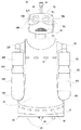
図2は、ロボット12の外観を示す正面図であり、この図2を参照して、ロボット12のハードウェアの構成について説明する。ロボット12は、台車20を含み、この台車20の下面には、ロボット12を自律移動させる2つの車輪22および1つの従輪24が設けられる。2つの車輪22は車輪モータ26(図3参照)によってそれぞれ独立に駆動され、ロボット12を前後左右任意の方向に動かすことができる。また、従輪24は車輪22を補助する補助輪である。このように、ロボット12は、配置された環境内を自由に移動可能なものである。ただし、ロボット12の移動機構は、車輪タイプに限定されず、公知の移動機構を適宜採用でき、たとえば2足歩行タイプの移動機構を採用することもできる。
FIG. 2 is a front view showing the appearance of the
台車20の上には、円柱形のセンサ取付パネル28が設けられ、このセンサ取付パネル28には、赤外線距離センサ30が取り付けられる。この赤外線距離センサ30は、ロボット12と周囲の物体(人や障害物など)との距離を計測するものである。
A cylindrical
また、センサ取付パネル28の上には、胴体32が直立するように設けられる。胴体32の前方中央上部(胸に相当する位置)には、上述した赤外線距離センサ30がさらに設けられる。これは、ロボット12の前方の主として人との距離を計測する。また、胴体32には、1つの全方位カメラ34が設けられる。全方位カメラ34は、たとえば背面側上端部のほぼ中央から延びる支柱36上に設けられる。全方位カメラ34は、ロボット12の周囲を撮影するものであり、後述する眼カメラ60とは区別される。この全方位カメラ34としては、たとえばCCDやCMOSのような固体撮像素子を用いるカメラを採用することができる。なお、これら赤外線距離センサ30および全方位カメラ34の設置位置は当該部位に限られず適宜変更され得る。
Further, the
胴体32の両側面上端部(肩に相当する位置)のそれぞれには、肩関節38Rおよび38Lによって、上腕40Rおよび40Lが設けられる。図示は省略するが、肩関節38Rおよび38Lのそれぞれは、直交する3軸の自由度を有する。すなわち、肩関節38Rは、直交する3軸のそれぞれの軸廻りにおいて上腕40Rの角度を制御できる。肩関節38Rの或る軸(ヨー軸)は、上腕40Rの長手方向に平行な軸であり、他の2軸(ピッチ軸、ロール軸)は、それにそれぞれ異なる方向から直交する軸である。同様に、肩関節38Lは、直交する3軸のそれぞれの軸廻りにおいて上腕40Lの角度を制御できる。肩関節38Lの或る軸(ヨー軸)は、上腕40Lの長手方向に平行な軸であり、他の2軸(ピッチ軸、ロール軸)は、それにそれぞれ異なる方向から直交する軸である。
また、上腕40Rおよび40Lのそれぞれの先端には、肘関節42Rおよび42Lを介して、前腕44Rおよび44Lが設けられる。図示は省略するが、肘関節42Rおよび42Lは、それぞれ1軸の自由度を有し、この軸(ピッチ軸)の軸廻りにおいて前腕44Rおよび44Lの角度を制御できる。
Further, forearms 44R and 44L are provided at the tips of the
前腕44Rおよび44Lのそれぞれの先端には、手に相当する球体46Rおよび46Lがそれぞれ固定的に設けられる。ただし、指や掌の機能が必要な場合には、人の手の形をした「手」を用いることも可能である。
また、図示は省略するが、台車20の前面、肩関節38R,38Lを含む肩に相当する部位、上腕40R,40L、前腕44R,44Lおよび球体46R,46Lには、それぞれ、接触センサ(図3で接触センサ48として包括的に示す。)が設けられている。台車20の前面の接触センサ48は、台車20への人や他の障害物の接触を検知する。したがって、ロボット12の移動中に障害物との接触があると、それを検知し、直ちに車輪22の駆動を停止してロボット12の移動を急停止させることができる。また、その他の接触センサ48は、主に、人がロボット12の当該各部位に触れたかどうかを検知する。なお、接触センサ48の設置位置はこれらに限定されず、適宜な位置(胸、腹、脇、背中、腰など)に設けられてよい。
Although illustration is omitted, a contact sensor (FIG. 3) is provided on each of the front surface of the
胴体32の中央上部(首に相当する位置)には首関節50が設けられ、さらにその上には頭部52が設けられる。図示は省略するが、首関節50は、3軸の自由度を有し、3軸の各軸廻りに角度制御可能である。或る軸(ヨー軸)はロボット12の真上(鉛直上向き)に向かう軸であり、他の2軸(ピッチ軸、ロール軸)は、それぞれ、それと異なる方向で直交する軸である。
A neck joint 50 is provided at the upper center of the body 32 (a position corresponding to the neck), and a
頭部52には、口に相当する位置に、スピーカ54が設けられる。スピーカ54は、ロボット12が、それの周辺の人に対して音声ないし音によってコミュニケーションを取るために用いられる。また、耳に相当する位置には、マイク56Rおよび56Lが設けられる。以下、右耳に相当するマイク56Rと左耳に相当するマイク56Lとをまとめて「マイク56」ということがある。マイク56は、周囲の音、とりわけコミュニケーションを実行する対象である人の声を取り込む。さらに、目に相当する位置には、眼球部58Rおよび58Lが設けられる。眼球部58Rおよび58Lは、それぞれ眼カメラ60Rおよび60Lを含む。以下、右の眼球部58Rと左の眼球部58Lとをまとめて「眼球部58」ということがあり、また、右の眼カメラ60Rと左の眼カメラ60Lとをまとめて「眼カメラ60」ということがある。
The
眼カメラ60は、ロボット12に接近した人の顔や他の部分ないし物体などを撮影して、それに対応する映像信号を取り込む。眼カメラ60としては、上述した全方位カメラ34と同様のカメラを用いることができる。たとえば、眼カメラ60は眼球部58内に固定され、眼球部58は眼球支持部(図示せず)を介して頭部52内の所定位置に取り付けられる。図示は省略するが、眼球支持部は、2軸の自由度を有し、それらの各軸廻りに角度制御可能である。たとえば、この2軸の一方は、頭部52の上へ向かう方向の軸(ヨー軸)であり、他方は、一方の軸に直交しかつ頭部52の正面側(顔)が向く方向に直交する方向の軸(ピッチ軸)である。眼球支持部がこの2軸の各軸廻りに回転されることによって、眼球部58ないし眼カメラ60の先端(正面)側が変位され、カメラ軸すなわち視線方向が移動される。なお、上述のスピーカ54、マイク56および眼カメラ60の設置位置は、これらに限定されず、適宜な位置に設けてられてよい。
The
図3は、ロボット12の電気的な構成を示すブロック図である。図3に示すように、ロボット12は、全体を制御するCPU62を含む。CPU62は、マイクロコンピュータ或いはプロセサとも呼ばれ、バス64を介して、メモリ66、モータ制御ボード68、センサ入力/出力ボード70および音声入力/出力ボード72等に接続される。
FIG. 3 is a block diagram showing an electrical configuration of the
メモリ66は、図示は省略するが、ROMやHDDおよびRAMを含む。ROMやHDDには、ロボット12の制御プログラムが予め記憶される。たとえば、人との間でコミュニケーション行動を実行するための行動制御プログラム、環境内を移動するための移動制御プログラム、および外部コンピュータとの間で必要な情報(制御データなど)を送受信するための通信プログラム等である。また、ROMやHDDには、コミュニケーション行動を実行する際にスピーカ54から発生すべき音声または声の音声データ(音声合成データ)、および配置される環境の地図データなどが適宜記憶される。また、RAMは、ワークメモリやバッファメモリとして用いられる。
Although not shown, the
モータ制御ボード68は、たとえばDSPで構成され、各腕や首関節50および眼球部58などの各軸モータの駆動を制御する。すなわち、モータ制御ボード68は、CPU62からの制御データを受け、右眼球部58Rの2軸のそれぞれの角度を制御する2つのモータ(図3では、まとめて「右眼球モータ」と示す。)74の回転角度を制御する。同様に、モータ制御ボード68は、CPU62からの制御データを受け、左眼球部58Lの2軸のそれぞれの角度を制御する2つのモータ(図3では、まとめて「左眼球モータ」と示す。)76の回転角度を制御する。
The
また、モータ制御ボード68は、CPU62からの制御データを受け、右肩関節38Rの直交する3軸のそれぞれの角度を制御する3つのモータと右肘関節42Rの角度を制御する1つのモータとの計4つのモータ(図3では、まとめて「右腕モータ」と示す。)78の回転角度を調節する。同様に、モータ制御ボード68は、CPU62からの制御データを受け、左肩関節38Lの直交する3軸のそれぞれの角度を制御する3つのモータと左肘関節42Lの角度を制御する1つのモータとの計4つのモータ(図3では、まとめて「左腕モータ」と示す。)80の回転角度を調節する。
The
さらに、モータ制御ボード68は、CPU62からの制御データを受け、首関節50の直交する3軸のそれぞれの角度を制御する3つのモータ(図3では、まとめて「頭部モータ」と示す。)82の回転角度を制御する。さらにまた、モータ制御ボード68は、CPU62からの制御データを受け、車輪22を駆動する2つのモータ(図3では、まとめて「車輪モータ」と示す。)26の回転角度を制御する。
Furthermore, the
なお、この実施例では、車輪モータ26を除くモータは、制御を簡素化するために、ステッピングモータ或いはパルスモータを用いるようにしてある。ただし、車輪モータ26と同様に、直流モータを用いるようにしてもよい。
In this embodiment, stepping motors or pulse motors are used for the motors other than the
センサ入力/出力ボード70もまた、同様に、DSPで構成され、各センサからの信号を取り込んでCPU62に与える。すなわち、赤外線距離センサ30のそれぞれからの反射時間に関するデータが、センサ入力/出力ボード70を通してCPU62に入力される。また、全方位カメラ34からの映像信号が、必要に応じてセンサ入力/出力ボード70で所定の処理を施された後、CPU62に入力される。眼カメラ60からの映像信号も、同様にして、CPU62に入力される。また、上述した複数の接触センサ48からの信号がセンサ入力/出力ボード70を介してCPU62に与えられる。
Similarly, the sensor input /
音声入力/出力ボード72もまた、同様に、DSPで構成され、CPU62から与えられる音声合成データに従った音声または声がスピーカ54から出力される。また、マイク56からの音声入力が、音声入力/出力ボード56を介してCPU62に取り込まれる。
Similarly, the voice input /
また、CPU62は、バス64を介して通信LANボード84に接続される。通信LANボード84は、DSPで構成され、CPU62から送られる送信データを無線通信装置86に与え、無線通信装置86から送信データを、たとえば、無線LANのようなネットワークを介して外部コンピュータに送信する。また、通信LANボード84は、無線通信装置86を介してデータを受信し、受信したデータをCPU62に与える。つまり、この通信LANボード84および無線通信装置86によって、ロボット12は外部コンピュータ(中央制御装置10や位置検出システム14)などと無線通信を行うことができる。
The
続いて、位置検出システム14について説明する。図4は、位置検出システム14が適用された環境の様子を概略的に示す図解図であり、図5は、位置検出システム14の電気的な構成を示す図解図である。図4および図5に示すように、位置検出システム14は、位置検出処理を実行するコンピュータ90、環境内に設置される複数のレーザレンジファインダ(LRF)92および無線IDタグリーダ94、ならびに各人96に装着される無線IDタグ98を含む。
Next, the
位置検出システム14のコンピュータ90は、パーソナルコンピュータやワークステーションのような汎用のコンピュータである。このコンピュータ90には、たとえばRS-232Cのような汎用のインタフェースを介して、複数のLRF92および無線IDタグリーダ94が接続される。これらの機器92,94によって検出されたデータは、コンピュータ90に送信され、その検出時刻と共にコンピュータ90のメモリの所定領域や外部のデータベースに適宜記憶される。また、コンピュータ90のメモリには、XY2次元平面座標系で表される各機器92,94の位置データや、環境の地図データが予め記憶されている。
The
LRF92は、レーザを照射し、物体に反射して戻ってくるまでの時間から当該物体までの距離を計測するセンサであり、たとえば、トランスミッタから照射したレーザを回転ミラーで反射させて、前方を扇状に一定角度ずつスキャンする。LRF92は、たとえば、高さ約90cmの台座の上に設置される。LRF92としては、SICK社製のLRF(型式 LMS 200)や、HOKUYO社製のLRF(型式 UTM‐30LX)等を用いることができる。
The
位置検出システム14では、コンピュータ90が、所定頻度(たとえば37.5回/秒)でLRF92からのセンサ情報(距離情報)を取得し、パーティクルフィルタや人形状モデルを用いて、人96の現在位置の変化を推定する。たとえば、LRF92によってスキャンされると、人96が存在しない可視区域、人96が存在する陰区域および人96のエッジが検出される。また、実空間に対応する仮想空間に対してパーティクルを均等にばら撒き、LRF92毎に尤度を求める。さらに、LRF92毎の尤度を統合することで、各パーティクルが更新される。そして、更新された各パーティクルによって人96の現在位置の変化が推定される。なお、尤度は、可視区域では一定値とし、陰区域では一定値とエッジの尤度との和となる。このようにして推定された現在位置の変化に基づいて人96の位置を求め、その位置の平面座標を示す数値(位置データ)を、時刻データと対応付けて、移動行動情報(移動軌跡データ)として人96ごとに分けて蓄積していく。また、たとえば、各人96の移動軌跡における一定時間ごとの変化量を時間で微分することによって、各人96の移動速度を算出する。なお、このようなLRFを用いた人の位置検出の詳細については、本件出願人が先に出願した特開2009−168578号公報に記載されているので参照されたい。
In the
無線IDタグ98は、環境内に存在する各人96に装着される。無線IDタグ98としては、たとえばRFID(Radio Frequency Identification)タグを用いることができる。RFIDは、電磁波を利用した非接触ICタグによる自動認識技術のことである。具体的には、RFIDタグは、識別情報用のメモリや通信用の制御回路等を備えるICチップおよびアンテナ等を含む。RFIDタグのメモリには、人96を識別可能な情報が予め記憶され、その識別情報が所定周波数の電磁波・電波などによってアンテナから出力される。
The
無線IDタグリーダ94は、たとえば環境内の天井に敷設されたレールに設置され、上述の無線IDタグ98からの出力情報を検出する。具体的には、無線IDタグリーダ94は、無線IDタグ98から送信される識別情報の重畳された電波を、アンテナを介して受信し、電波信号を増幅し、当該電波信号から識別情報を分離し、当該情報を復調(デコード)する。また、無線IDタグリーダ94は、検出した電波強度に基づいて、無線IDタグ98との距離を検出する。
The wireless
この実施例では、コンピュータ90は、たとえば5回/秒の頻度で無線IDタグリーダ94によって検出される無線IDタグ98からのセンサ情報(識別情報および距離情報)を取得する。そして、取得した識別情報に基づいて、その無線IDタグ98を所持している人96を特定する。また、同一の無線IDタグ98に対して3つの無線IDタグリーダ94から取得した距離情報と、予め記憶した無線IDタグリーダ94の位置データとに基づいて、その無線IDタグ98を所持している人96の位置座標を特定する。
In this embodiment, the
そして、位置検出システム12のコンピュータ90は、各機器92,94によって検出されたセンサ情報(測位データ)或いはセンサ情報から推定した情報を統合し、各人96の位置座標(X,Y)をその検出時刻tに対応付けて、メモリ或いはデータベースに記憶する。つまり、人96(識別情報またはID番号)ごとに、時系列データとしてその移動軌跡が記憶される。このような移動行動情報は、中央制御装置10からの要求に応じて、或いは所定時間ごとに、中央制御装置10に随時送信される。
Then, the
なお、位置検出システム14は、各人96の位置座標ないし位置履歴を検出できるものであれば、上述の構成のものに限定されず、たとえば、赤外線センサ、ビデオカメラ、床センサ、或いはGPS等を適宜利用するものであってもよい。また、人96を個別に識別する必要がない場合には、無線IDタグリーダ94および無線IDタグ98を必ずしも備える必要はない。
The
図1に戻って、中央制御装置(流れ状態判別装置)10は、コンピュータ110を含み、上述のような位置検出システム14から随時送信される各人96の移動行動情報、および予め大量に蓄積された人々の移動行動情報に基づいて、環境内における人の流れの状態(流れの発生や終息、継続など)を予測する。
Returning to FIG. 1, the central control device (flow state determination device) 10 includes a
コンピュータ110は、たとえば、CPU112、メモリ114、通信装置116、入力装置および表示装置などを備える汎用のパーソナルコンピュータやワークステーションである。コンピュータ110のメモリ112は、HDDやROMおよびRAMを含む。HDDないしROMには、中央制御装置10の動作を制御するためのプログラムが記憶されており、CPU112は、このプログラムに従って処理を実行する。たとえば、HDDないしROMには、環境内の人の流れを予測するための予測プログラム(軌跡判定プログラム、特徴量抽出プログラムおよび流れ状態判別プログラム等)、およびロボット12や位置検出システム14等の外部コンピュータとの間で必要な情報(ロボット12の制御データや人96の移動行動情報など)を送受信するための通信プログラム等が記憶される。RAMは、CPU112の作業領域またはバッファ領域として使用される。通信装置116は、たとえば無線LANやインタネットのようなネットワークを介して、外部コンピュータと通信するためのものである。
The
また、中央制御装置10のコンピュータ110には、流れデータベース(DB)118が接続される。流れDB118は、詳細は後述するように、代表移動軌跡Fの軌跡データなどが記憶されるデータベースである(図10参照)。なお、流れDB118は、図1に示すようにコンピュータ110の外部に設けられてもよいし、コンピュータ110内のHDD等に設けられてもよい。
A flow database (DB) 118 is connected to the
このような中央制御装置10では、上述のように、適用環境において予め大量に蓄積された人々の移動行動情報を利用する。この実施例では、大量に蓄積された人々の移動行動情報に基づいて、代表移動軌跡Fおよび人の流れの状態を判別するための判別機が予め作成される。図6は、中央制御装置10(ロボット制御システム100)が適用される環境(商業施設)の一例を示す地図である。図6に示すように、この環境の中央部にはエスカレータ(Esc)があり、その左側には階段がある。また、図6に斜線で示す部分は、店舗や柱などの構造物が存在し、人96やロボット12の通路とはならない部分である。
As described above, the
以下、予め作成される代表移動軌跡Fおよび判別機について説明する。先ず、位置検出システム14などを用いて、一定期間(たとえば1週間)、環境内に存在する全ての人の位置履歴(移動行動情報)を検出してデータベースに蓄積していく。蓄積した移動行動情報を分析すると、環境内の人々が通る道(つまり人の流れが生じる経路)は或る程度決まっていることが分かるので、代表的な移動経路を代表移動軌跡Fとして設定する。具体例を挙げて説明すると、図7に示すように、蓄積した移動行動情報を分析した結果、環境内の通路を右から左へ移動する、或いは左から右へ移動する主要な流れの存在が観測されたとする。また、階段やエスカレータから主要な流れに合流したり、主要な流れから階段やエスカレータに向かったり、柱に沿って移動したりする中程度の流れや、立ち止まっている人を避けるための副次的な流れの存在が観測されたとする。このような場合、これらの観測された代表的な流れ(移動経路)のそれぞれが、代表移動軌跡Fとして設定され得る。なお、代表移動軌跡Fは、1つであってもよいし、複数であってもよい。
Hereinafter, the representative movement trajectory F and the discriminator created in advance will be described. First, the
なお、適用環境の全体を1つの領域とし、上述のような代表的な流れのそれぞれを代表移動軌跡Fとすることもできるが、環境を複数の領域に区分して、上述のような代表的な流れの一部分のそれぞれを代表移動軌跡Fとすることもできる。たとえば、図8に示すように、環境を複数の領域に区分して管理し、図9に示すように、領域ごとに代表移動軌跡Fを設定することもできる。なお、環境の区分の仕方、すなわち領域の大きさ、数および形状などは、適用環境に応じて適宜設定され、たとえば、格子状に規則正しく区分することもできるし、不定形状に不規則に区分することもできる。また、このような環境の区分は、開発者や管理者が手動で詳細に設定するようにしてもよいし、k−means法などを利用して自動的に設定するようにしてもよい。 The entire applicable environment can be set as one region, and each of the representative flows as described above can be set as the representative movement trajectory F. However, the environment is divided into a plurality of regions, and the representative flows as described above. Each part of the simple flow may be used as the representative movement trajectory F. For example, as shown in FIG. 8, the environment can be divided into a plurality of areas and managed, and a representative movement trajectory F can be set for each area as shown in FIG. Note that the environment classification method, that is, the size, number, and shape of the region is appropriately set according to the application environment. For example, it can be regularly classified into a lattice shape, or irregularly divided into an indefinite shape. You can also Such an environment classification may be set manually in detail by a developer or an administrator, or may be automatically set using a k-means method or the like.
このような代表移動軌跡Fに関する情報は、流れDB118に記憶される。図10には、流れDB118に記憶されるテーブルの一例を示す。図10に示すように、流れDB118には、各代表移動軌跡Fに設定されたIDに対応付けて、各代表移動軌跡Fの軌跡データが記憶される。軌跡データには、移動軌跡を構成する座標(X,Y)が含まれる。また、軌跡データには、その座標で行われた行動態様(A)を含むようにしてもよい。行動態様(A)としては、移動速度に基づいて推定される「立ち止まる」、「ゆっくり進む」および「早歩きで進む」などが含まれる。たとえば、IDが「Fa」である代表移動軌跡Fに対応付けて、「(Xa1,Ya1,Aa1),(Xa2,Ya2,Aa2),…」の軌跡データが記憶される。
Information regarding such a representative movement trajectory F is stored in the
代表移動軌跡Fが設定(作成)されると、続いて、機械学習の手法を用いて、代表移動軌跡Fごとに人の流れの状態を判別するための判別機を作成する。機械学習の手法としては、サポートベクターマシン(SVM)、ニューラルネットワーク、ブースティング等の公知の手法を用いることができる。以下には、一例としてSVMを用いる場合について説明するが、SVMは広く一般的な方法であるため、詳細な説明は省略する。 When the representative movement trajectory F is set (created), a discriminator for discriminating the state of human flow is created for each representative movement trajectory F using a machine learning technique. As a machine learning method, a known method such as a support vector machine (SVM), a neural network, or boosting can be used. In the following, a case where SVM is used as an example will be described, but since SVM is a widely general method, detailed description thereof is omitted.
SVMは、予めラベル付けがされた複数の教師データ(データセット)から特徴量を抽出し、学習することによって構築される。ここで、複数の教師データは、開発者などによって予め作成されるものであり、教師データのそれぞれには、人の流れの状態についてのラベルが手作業で付与される。教師データは、たとえば、n秒間の移動軌跡などの時系列データであり、蓄積した移動行動情報を開発者などが複数人で観察して、その流れの状態であるとして異論のない部分が教師データとして扱われる。ただし、機械的に教師データを定義することも可能である。 The SVM is constructed by extracting feature values from a plurality of pre-labeled teacher data (data sets) and learning. Here, a plurality of teacher data is created in advance by a developer or the like, and each of the teacher data is manually provided with a label about a human flow state. The teacher data is, for example, time-series data such as a movement trajectory for n seconds, and a plurality of developers or the like observe the accumulated movement behavior information. Are treated as However, it is also possible to define teacher data mechanically.
教師データに付与されるラベルとしては、「もうすぐ流れが発生する」、「もうすぐ流れがなくなる(終息する)」、「流れのある状況が続く(継続する)」、「流れのない状況が続く」、「流れがある」、「流れがない」、「流れの停滞が生じる(混雑する)」、「流れの停滞が解消される」等がある。なお、「人の流れ」とは、複数の人の移動態様を全体的な視点で表現するものであり、どのような状態を「流れがある」や「流れがない」等と判断するか、また、どのような状態のラベルを採用するかは、開発者などが適宜設定できる。 The labels given to the teacher data are “flow will soon occur”, “flow will soon stop (terminate)”, “flow will continue (continue)”, “no flow will continue” , “There is a flow”, “there is no flow”, “the stagnation of the flow (congestion)”, “the stagnation of the flow is resolved”, and the like. In addition, “person flow” expresses the movement aspect of multiple people from the overall viewpoint, and what kind of state is judged as “flow” or “no flow”, etc. Further, the developer or the like can appropriately set the state of the label to be used.
また、教師データから抽出される特徴量としては、その軌跡(流れ)に存在する総人数、平均移動速度、人密度(単位長さ当たりの人数)、およびグループ数などがある。ただし、特徴量の種類および数は、一意に定まっているわけではなく、適用環境や代表移動軌跡Fに応じて、様々な統計量が特徴量として用いられ得る。 Further, the feature quantity extracted from the teacher data includes the total number of people, the average moving speed, the human density (number of people per unit length), the number of groups, and the like existing in the trajectory (flow). However, the type and number of feature quantities are not uniquely determined, and various statistical quantities can be used as feature quantities according to the application environment and the representative movement trajectory F.
中央制御装置10では、このような機械学習の手法による判別機を用いて、各代表移動軌跡Fの人の流れの状態を判別し、環境内の人の流れを予測する。以下、中央制御装置10が環境内の人の流れを予測する方法(動作)について説明する。
The
先ず、環境内に存在する人96がどの代表移動軌跡Fに属しているか(乗っているか)を判定することによって、各人96を代表移動軌跡Fのいずれかに振り分ける。ただし、どの代表移動軌跡Fにも属さない人96も存在し得る。判定結果は、メモリ112等に適宜記憶される。具体的には、環境内に存在する全ての人について、数秒間ないし数十秒間の直近の移動軌跡データ(位置履歴データ)を位置検出システム14から取得し、メモリ112等に一時記憶する。そして、取得した各人96の移動軌跡データのそれぞれと代表移動軌跡Fのそれぞれとを比較して、各人96の移動軌跡データと所定値以上の類似度を有する代表移動軌跡Fが存在する場合に、その人96はその代表移動軌跡Fに属していると判断する。また、所定値以上の類似度を有する複数の代表移動軌跡Fが存在する場合には、類似度が最も大きい代表移動軌跡Fに属していると判断し、所定値以上の類似度を有する代表移動軌跡Fがない場合は、どの代表移動軌跡Fにも属さないと判断する。各人96の移動軌跡データと代表移動軌跡Fとの類似度の判定には、DPマッチング等の公知の手法を用いるとよい。なお、DPマッチングを用いて軌跡の類似度を判定する手法については、本件出願人が先に出願した特開2010−231470号公報に記載されているので参照されたい。
First, each representative 96 is assigned to one of the representative movement trajectories F by determining which representative movement trajectory F the
各人96の各代表移動軌跡Fへの振り分けが終了すると、各代表移動軌跡Fのそれぞれについて人の流れの状態を判別する。具体的には、代表移動軌跡Fのそれぞれについて、その代表移動軌跡Fに属する人々から特徴量、たとえば、総人数、平均移動速度、人密度およびグループ数などを抽出する。そして、抽出した特徴量を上述の予め作成した判別機によって判別させることにより、その代表移動軌跡Fの人の流れの状態を判別する。つまり、代表移動軌跡Fのそれぞれが、「もうすぐ(たとえば数十秒後)流れが発生する」、「もうすぐ流れがなくなる(終息する)」、「流れのある状況が続く」および「流れのない状況が続く」等のいずれの状態であるかを判別する。代表移動軌跡Fごとに判別されたこれらの流れ情報を統合することによって、環境内の或る場所にもうすぐ流れが発生する、或る場所の流れがもうすぐなくなる等が分かる。すなわち、環境内における人の流れの発生、終息および継続などを予測することができる。
When the distribution of each
そして、ロボット制御システム100では、このように中央制御装置10によって予測された環境内の人の流れに関する情報は、ロボット12の行動の決定(選択)に利用される。この実施例では、中央制御装置10は、ロボット制御装置としても機能し、環境内の人の流れに応じた制御データが、中央制御装置10からロボット12に対して送信される。ロボット12は、中央制御装置10から送信される制御データに従って動作を制御する。
In the
たとえば、ロボット12のタスクが観光案内である場合には、ロボット12は、賑やかな場所、つまり流れのある状況が続く場所やもうすぐ流れが生じる場所、或いは複数の流れがある場所などを通るように制御される。また、たとえば、ロボット12のタスクが荷物運搬である場合には、ロボット12は、空いている場所、つまり流れのない状況が続く場所やもうすぐ流れがなくなる場所を通るように制御される。さらに、たとえば、ロボット12のタスクが流れ制御(誘導整理)である場合には、混雑している場所に移動し、その場所の状態がもうすぐ流れがなくなる状態になるまで、その場所で人に声をかけるように制御される。ただし、これらは単なる例示であり、環境内の人の流れに応じてどのようにロボット12の行動を制御するかは、適宜決定できる。
For example, when the task of the
なお、中央制御装置10からロボット12に対して制御データを送信する代わりに、環境内の人の流れに関する情報自体をロボット12に送信し、ロボット12(CPU62)自身が、環境内の人の流れに応じて自身の行動を決定することもできる。また、環境内の人の流れに応じたロボット12の制御データを生成する他のコンピュータを、中央制御装置10とロボット12との間に介在させ、ロボット制御装置として機能させることもできる。さらに、位置検出システム14のコンピュータ90の機能を、中央制御装置10のコンピュータ110が実行することもできる。
Instead of transmitting control data from the
続いて、フロー図を用いてロボット制御システム100(中央制御装置10)の動作を説明する。具体的には、図1に示したコンピュータ110のCPU112が、図11に示すフロー図に従って全体処理を実行する。
Next, the operation of the robot control system 100 (central control apparatus 10) will be described using a flowchart. Specifically, the
図11を参照して、CPU112は、ステップS1で終了処理があるか否かを判断する。たとえば、この全体処理を終了するための操作がオペレータ等によって行われたか否かを判断する。ステップS1で“YES”の場合、すなわち終了処理がある場合には、この全体処理を終了する。一方、ステップS1で“NO”の場合には、処理はステップS3に進む。
Referring to FIG. 11,
ステップS3では、人96のIDを示す変数Xを初期化する(X=0)。たとえば、環境内に存在する人96のIDを0〜Lとした場合、X=0に設定する。続くステップS5では、X=Lか否かを判断する。つまり、環境内に存在する全ての人96に対して軌跡判定処理(ステップS7およびS9の処理)を実行したか否かを判断する。ステップS5で“YES”の場合、すなわち環境内に存在する全ての人96に対して軌跡判定処理を行った場合には、ステップS13に進む。一方、ステップS5で“NO”の場合、すなわち軌跡判定処理を行っていない人96が存在する場合には、ステップS7に進む。
In step S3, a variable X indicating the ID of the
ステップS7では、IDがXの人96の位置履歴を取得する。すなわち、当該人96の数秒間ないし数十秒間の直近の位置履歴データ(移動行動情報)を、通信装置116を介して位置検出システム14から取得する。続くステップ9では、当該人96の移動行動情報と代表移動軌跡Fのそれぞれとを比較して、当該人96がどの代表移動軌跡Fに属しているかを判定する。すなわち、DPマッチング等を用いて当該人96の位置履歴データと各代表移動軌跡Fとの類似度を算出する。そして、たとえば所定値以上の類似度を有する代表移動軌跡Fが存在する場合には、その人96はその代表移動軌跡Fに属していると判定する。この判定結果は、メモリ114等に適宜記憶される。続くステップS11では、変数Xをインクリメントして(X=X+1)、ステップS5に戻る。
In step S7, the position history of the
ステップS13では、代表移動軌跡FのID(Fa,Fb,Fc,…)を示す変数Yを初期化する(Y=0)。たとえば、環境内に設定した代表移動軌跡のIDを0〜Mとした場合、Y=0に設定する。続くステップS15では、Y=Mか否かを判断する。つまり、環境内に設定した全ての代表移動軌跡Fに対して流れ状態判別処理(ステップS17およびS19の処理)を実行したか否かを判断する。ステップS15で“YES”の場合、すなわち環境内に設定した全ての代表移動軌跡Fに対して流れ状態判定処理を行った場合には、ステップS23に進む。一方、ステップS15で“NO”の場合、すなわち流れ状態判定処理を行っていない代表移動軌跡Fが存在する場合には、ステップS17に進む。 In step S13, a variable Y indicating the ID (Fa, Fb, Fc,...) Of the representative movement locus F is initialized (Y = 0). For example, when the ID of the representative movement trajectory set in the environment is 0 to M, Y = 0 is set. In a succeeding step S15, it is determined whether or not Y = M. That is, it is determined whether or not the flow state determination process (the processes in steps S17 and S19) has been executed for all the representative movement trajectories F set in the environment. If “YES” in the step S15, that is, if the flow state determination process is performed for all the representative movement trajectories F set in the environment, the process proceeds to a step S23. On the other hand, if “NO” in the step S15, that is, if there is a representative movement locus F that has not been subjected to the flow state determination process, the process proceeds to a step S17.
ステップS17では、IDがYの代表移動軌跡Fに属する人々から特徴量を抽出する。すなわち、ステップS9で当該代表移動軌跡Fに属すると判定された人96から、その代表移動軌跡Fに属する人の総数、平均移動速度、人密度、およびグループ数など特徴量を抽出する。続くステップS19では、判別機を利用して人の流れの状態を判別する。すなわち、ステップS17で抽出した特徴量を予め作成した判別機によって判別させることにより、その代表移動軌跡Fの人の流れの状態を判別する。たとえば、「もうすぐ流れが発生する」や「もうすぐ流れがなくなる」等のいずれの状態であるかを判別する。この判別結果は、メモリ114等に適宜記憶される。
In step S17, feature amounts are extracted from people belonging to the representative movement locus F whose ID is Y. That is, feature quantities such as the total number of people belonging to the representative movement locus F, the average movement speed, the human density, and the number of groups are extracted from the
ステップS23では、環境内の人の流れに応じた制御データをロボット12に送信する。たとえば、ロボット12に設定されたタスクが観光案内である場合には、もうすぐ流れが生じる場所などを通るようにロボット12を制御するための制御データを作成し、通信装置116を介してロボット12に送信する。
In step S23, control data corresponding to the flow of people in the environment is transmitted to the
この実施例によれば、予め環境内に設定した代表移動軌跡Fの流れの状態を判別することによって、環境内の或る場所にもうすぐ流れが発生する、或る場所の流れがもうすぐなくなる等が予測できる。すなわち、環境内における人の流れの発生、終息および継続などを予測することができる。 According to this embodiment, by determining the flow state of the representative movement trajectory F set in the environment in advance, a flow will soon occur in a certain place in the environment, or a flow in a certain place will soon disappear. Predictable. That is, it is possible to predict the occurrence, termination, and continuation of human flow in the environment.
また、環境内の人の流れを予測できるので、人の流れに応じた自然な行動をロボット12に実行させることができる。
Moreover, since the flow of the person in the environment can be predicted, the
なお、上述の実施例では、代表移動軌跡Fに属する人々の特徴量から、その代表移動軌跡Fの人の流れの状態を判別するようにした、つまり代表移動軌跡Faの特徴量から代表移動軌跡Faの人の流れの状態を判別したが、これに限定されない。たとえば、代表移動軌跡F同士の相関関係を予め計算しておくことによって、或る代表移動軌跡Fに属する人々の特徴量から、他の代表移動軌跡Fの人の流れの状態を判別することもできる。また、たとえば、或る領域内に含まれる代表移動軌跡群(代表移動軌跡Fの集まり)に属する人々の特徴量から、その領域の人の流れの状態を判別することもできる。 In the above-described embodiment, the state of the person's flow in the representative movement locus F is determined from the feature amount of the people belonging to the representative movement locus F. That is, the representative movement locus is determined from the feature amount of the representative movement locus Fa. Although the state of the flow of Fa is determined, the present invention is not limited to this. For example, by calculating the correlation between representative movement trajectories F in advance, it is also possible to determine the state of a person's flow in another representative movement trajectory F from the feature amount of people belonging to a certain representative movement trajectory F. it can. Further, for example, it is possible to determine the state of the flow of people in the area from the feature amount of people belonging to the representative movement locus group (collection of representative movement locus F) included in a certain area.
また、上述の実施例では、ロボット12の一例として、身体動作や発話を用いて人との間でコミュニケーション行動を実行する相互作用指向のロボットを挙げて説明したが、ロボット12の種類は特に限定されない。
Further, in the above-described embodiment, as an example of the
さらに、上述の実施例では、予測した人の流れの情報に基づいて、ロボット12の行動を制御するようにしたが、これに限定されず、デジタルサイネージや信号機などの他の機器の制御に利用することもできるし、警備員などの人に指示を出すこともできる。たとえば、デジタルサイネージを制御するときには、デジタルサイネージの視野範囲が、流れがある状態やもうすぐ流れる状態になったときのみに、広告を提示するような使用方法が考えられる。
Further, in the above-described embodiment, the behavior of the
なお、上で挙げた時間や回数などの具体的数値は、いずれも単なる一例であり、必要に応じて適宜変更可能である。 Note that the specific numerical values such as the time and the number of times mentioned above are merely examples, and can be changed as appropriate.
10 …中央制御装置(流れ状態判別装置)
12 …ロボット
14 …位置検出システム
62 …ロボットのCPU
66 …ロボットのメモリ
86 …ロボットの通信装置
90 …位置検出システムのコンピュータ
92 …レーザレンジファインダ
94 …無線IDタグリーダ
100 …ロボット制御システム
110 …中央制御装置のコンピュータ
112 …中央制御装置のCPU
114 …中央制御装置のメモリ
116 …中央制御装置の通信装置
118 …流れデータベース
F …代表移動軌跡
10 ... Central control device (flow state discrimination device)
12 ...
DESCRIPTION OF
114 ... central control unit memory 116 ... central control
Claims (5)
前記環境内において蓄積した複数の人の移動行動情報に基づいて予め作成される1または複数の代表移動軌跡に関する情報を記憶する記憶手段、
前記環境内に存在する複数の人の位置履歴を検出する検出手段、
前記検出手段によって検出した前記位置履歴に基づいて、前記環境内に存在する複数の人のそれぞれについて、いずれの前記代表移動軌跡に属するかを判定する軌跡判定手段、
前記代表移動軌跡のそれぞれについて、前記判定手段によって当該代表移動軌跡に属すると判断された人から特徴量を抽出する抽出手段、および
前記抽出手段によって抽出された前記特徴量に基づいて、前記代表移動軌跡のそれぞれについて人の流れの状態を判別する状態判別手段を備える、流れ状態判別装置。 A flow state determination device that predicts the flow of people in the environment,
Storage means for storing information on one or more representative movement trajectories created in advance based on movement behavior information of a plurality of persons accumulated in the environment;
Detecting means for detecting position histories of a plurality of persons existing in the environment;
Trajectory determination means for determining which of the representative movement trajectories each of a plurality of persons existing in the environment based on the position history detected by the detection means,
For each of the representative movement trajectories, the representative movement is extracted based on the extraction means for extracting a feature amount from a person determined to belong to the representative movement locus by the determination means, and the feature amount extracted by the extraction means. A flow state discriminating device comprising state discriminating means for discriminating a human flow state for each of the trajectories.
(a)前記環境内における複数の人の移動行動情報を蓄積し、
(b)前記ステップ(a)で蓄積した移動行動情報に基づいて、前記環境内の人が通る代表的な移動経路を1または複数の代表移動軌跡として設定し、
(c)前記ステップ(b)で設定した代表移動軌跡のそれぞれについて、人の流れの状態を判別するための判別機を作成し、
(d)前記環境内に存在する複数の人の位置履歴を検出し、
(e)前記ステップ(d)で検出された複数の人の位置履歴に基づいて、当該複数の人のそれぞれがいずれの前記代表移動軌跡に属するかを判定し、
(f)前記代表移動軌跡のそれぞれについて、前記ステップ(e)で当該代表移動軌跡に属すると判断された人から特徴量を抽出し、そして
(g)前記代表移動軌跡のそれぞれについて、前記ステップ(c)で作成した判別機によって前記ステップ(f)で抽出した特徴量を判別させることにより、人の流れの状態を判別する、流れ状態判別方法。 A flow state determination method for predicting the flow of people in an environment,
(A) Accumulating movement behavior information of a plurality of people in the environment;
(B) Based on the movement behavior information accumulated in the step (a), a representative movement route through which a person in the environment passes is set as one or a plurality of representative movement trajectories,
(C) For each of the representative movement trajectories set in step (b), create a discriminator for discriminating the state of human flow,
(D) detecting position histories of a plurality of people existing in the environment;
(E) Based on the position history of the plurality of people detected in the step (d), it is determined which of the representative movement trajectories each of the plurality of people belongs to,
(F) For each of the representative movement trajectories, a feature amount is extracted from the person determined to belong to the representative movement trajectory in step (e), and (g) for each of the representative movement trajectories, the step ( A flow state determination method for determining a state of a human flow by determining the feature amount extracted in step (f) by the classifier created in c).
前記環境内に存在する複数の人の位置履歴を検出する検出手段、
前記検出手段によって検出した前記位置履歴に基づいて、前記環境内に存在する複数の人のそれぞれについて、いずれの前記代表移動軌跡に属するかを判定する軌跡判定手段、
前記代表移動軌跡のそれぞれについて、前記判定手段によって当該代表移動軌跡に属すると判断された人から特徴量を抽出する抽出手段、および
前記抽出手段によって抽出された前記特徴量に基づいて、前記代表移動軌跡のそれぞれについて人の流れの状態を判別する状態判別手段として機能させる、流れ状態判別プログラム。 A processor for a flow state discriminating apparatus having storage means for storing information on one or more representative movement trajectories created in advance based on movement behavior information of a plurality of persons accumulated in the environment,
Detecting means for detecting position histories of a plurality of persons existing in the environment;
Trajectory determination means for determining which of the representative movement trajectories each of a plurality of persons existing in the environment based on the position history detected by the detection means,
For each of the representative movement trajectories, the representative movement is extracted based on the extraction means for extracting a feature amount from a person determined to belong to the representative movement locus by the determination means, and the feature amount extracted by the extraction means. A flow state determination program that functions as a state determination unit that determines the state of a person's flow for each trajectory.
前記環境内において蓄積した複数の人の移動行動情報に基づいて予め作成される1または複数の代表移動軌跡に関する情報を記憶する記憶手段、
前記環境内に存在する複数の人の位置履歴を検出する検出手段、
前記検出手段によって検出した前記位置履歴に基づいて、前記環境内に存在する複数の人のそれぞれについて、いずれの前記代表移動軌跡に属するかを判定する軌跡判定手段、
前記代表移動軌跡のそれぞれについて、前記判定手段によって当該代表移動軌跡に属すると判断された人から特徴量を抽出する抽出手段、
前記抽出手段によって抽出された前記特徴量に基づいて、前記代表移動軌跡のそれぞれについて人の流れの状態を判別する状態判別手段、および
前記状態判別手段によって判別された結果に基づいて、前記ロボットの動作を制御する制御手段を備える、ロボット制御システム。 A robot control system including a robot that provides services in an environment where people coexist,
Storage means for storing information on one or more representative movement trajectories created in advance based on movement behavior information of a plurality of persons accumulated in the environment;
Detecting means for detecting position histories of a plurality of persons existing in the environment;
Trajectory determination means for determining which of the representative movement trajectories each of a plurality of persons existing in the environment based on the position history detected by the detection means,
For each of the representative movement trajectories, an extraction means for extracting a feature amount from a person determined to belong to the representative movement trajectory by the determination means;
Based on the feature amount extracted by the extraction means, state determination means for determining the state of human flow for each of the representative movement trajectories, and based on the result determined by the state determination means, A robot control system comprising a control means for controlling operation.
Priority Applications (1)
| Application Number | Priority Date | Filing Date | Title |
|---|---|---|---|
| JP2011067585A JP2012203646A (en) | 2011-03-25 | 2011-03-25 | Flow-state discrimination device, flow-state discrimination method, flow-state discrimination program, and robot control system using the device, method and program |
Applications Claiming Priority (1)
| Application Number | Priority Date | Filing Date | Title |
|---|---|---|---|
| JP2011067585A JP2012203646A (en) | 2011-03-25 | 2011-03-25 | Flow-state discrimination device, flow-state discrimination method, flow-state discrimination program, and robot control system using the device, method and program |
Publications (1)
| Publication Number | Publication Date |
|---|---|
| JP2012203646A true JP2012203646A (en) | 2012-10-22 |
Family
ID=47184594
Family Applications (1)
| Application Number | Title | Priority Date | Filing Date |
|---|---|---|---|
| JP2011067585A Pending JP2012203646A (en) | 2011-03-25 | 2011-03-25 | Flow-state discrimination device, flow-state discrimination method, flow-state discrimination program, and robot control system using the device, method and program |
Country Status (1)
| Country | Link |
|---|---|
| JP (1) | JP2012203646A (en) |
Cited By (4)
| Publication number | Priority date | Publication date | Assignee | Title |
|---|---|---|---|---|
| WO2016104265A1 (en) * | 2014-12-25 | 2016-06-30 | 株式会社エクォス・リサーチ | Moving body |
| JP2017177228A (en) * | 2016-03-28 | 2017-10-05 | 株式会社国際電気通信基礎技術研究所 | Service provision robot system |
| JP2021510433A (en) * | 2018-01-12 | 2021-04-22 | ゼネラル・エレクトリック・カンパニイ | Systems and methods for autonomous motion planning and navigation of robots Description of federal-funded research and development |
| JP7422719B2 (en) | 2021-09-30 | 2024-01-26 | Kddi株式会社 | Estimation device, program, and method for estimating power consumption of a mobile object when traveling on a road |
Citations (5)
| Publication number | Priority date | Publication date | Assignee | Title |
|---|---|---|---|---|
| JP2005346617A (en) * | 2004-06-07 | 2005-12-15 | East Japan Railway Co | Passer-by behavior analysis system |
| JP2010205015A (en) * | 2009-03-04 | 2010-09-16 | Advanced Telecommunication Research Institute International | Group behavior estimation device and service provision system |
| JP2010231470A (en) * | 2009-03-27 | 2010-10-14 | Advanced Telecommunication Research Institute International | Information providing system |
| JP2010231359A (en) * | 2009-03-26 | 2010-10-14 | Advanced Telecommunication Research Institute International | Remote control device |
| JP2010287251A (en) * | 2003-08-07 | 2010-12-24 | National Institute Of Advanced Industrial Science & Technology | Traffic congestion prediction program, computer readable recording medium recording the same and traffic congestion prediction apparatus, and navigation program, computer readable storage medium recording the same and navigation apparatus |
-
2011
- 2011-03-25 JP JP2011067585A patent/JP2012203646A/en active Pending
Patent Citations (5)
| Publication number | Priority date | Publication date | Assignee | Title |
|---|---|---|---|---|
| JP2010287251A (en) * | 2003-08-07 | 2010-12-24 | National Institute Of Advanced Industrial Science & Technology | Traffic congestion prediction program, computer readable recording medium recording the same and traffic congestion prediction apparatus, and navigation program, computer readable storage medium recording the same and navigation apparatus |
| JP2005346617A (en) * | 2004-06-07 | 2005-12-15 | East Japan Railway Co | Passer-by behavior analysis system |
| JP2010205015A (en) * | 2009-03-04 | 2010-09-16 | Advanced Telecommunication Research Institute International | Group behavior estimation device and service provision system |
| JP2010231359A (en) * | 2009-03-26 | 2010-10-14 | Advanced Telecommunication Research Institute International | Remote control device |
| JP2010231470A (en) * | 2009-03-27 | 2010-10-14 | Advanced Telecommunication Research Institute International | Information providing system |
Cited By (8)
| Publication number | Priority date | Publication date | Assignee | Title |
|---|---|---|---|---|
| WO2016104265A1 (en) * | 2014-12-25 | 2016-06-30 | 株式会社エクォス・リサーチ | Moving body |
| CN107111317A (en) * | 2014-12-25 | 2017-08-29 | 株式会社爱考斯研究 | Moving body |
| JPWO2016104265A1 (en) * | 2014-12-25 | 2017-09-14 | 株式会社エクォス・リサーチ | Moving body |
| US10331140B2 (en) | 2014-12-25 | 2019-06-25 | Equos Research Co., Ltd. | Moving body |
| CN107111317B (en) * | 2014-12-25 | 2020-07-17 | 株式会社爱考斯研究 | Moving body |
| JP2017177228A (en) * | 2016-03-28 | 2017-10-05 | 株式会社国際電気通信基礎技術研究所 | Service provision robot system |
| JP2021510433A (en) * | 2018-01-12 | 2021-04-22 | ゼネラル・エレクトリック・カンパニイ | Systems and methods for autonomous motion planning and navigation of robots Description of federal-funded research and development |
| JP7422719B2 (en) | 2021-09-30 | 2024-01-26 | Kddi株式会社 | Estimation device, program, and method for estimating power consumption of a mobile object when traveling on a road |
Similar Documents
| Publication | Publication Date | Title |
|---|---|---|
| US20210146540A1 (en) | Method of identifying dynamic obstacle and robot implementing same | |
| JP5366048B2 (en) | Information provision system | |
| US8588464B2 (en) | Assisting a vision-impaired user with navigation based on a 3D captured image stream | |
| JP5747191B2 (en) | Mobile remote control system and control program therefor | |
| JP5324286B2 (en) | Network robot system, robot control apparatus, robot control method, and robot control program | |
| US11330951B2 (en) | Robot cleaner and method of operating the same | |
| JP5764795B2 (en) | Mobile robot, mobile robot learning system, and mobile robot behavior learning method | |
| JP5318623B2 (en) | Remote control device and remote control program | |
| KR20170097017A (en) | Customer service robot and related systems and methods | |
| US20200008639A1 (en) | Artificial intelligence monitoring device and method of operating the same | |
| JP5617562B2 (en) | Mobile robot | |
| JP2006192563A (en) | Target object detection apparatus and robot provided with the same | |
| KR20180040839A (en) | Airport robot, and airport robot system including same | |
| US11607801B2 (en) | Artificial intelligence robot for managing movement of object using artificial intelligence and method of operating the same | |
| Rajendran et al. | Design and implementation of voice assisted smart glasses for visually impaired people using google vision api | |
| KR20190105216A (en) | Artificial intelligence robot cleaner | |
| JP2007152442A (en) | Robot guiding system | |
| JP2010224878A (en) | Objective behavior estimation device and service providing system | |
| JP2012203646A (en) | Flow-state discrimination device, flow-state discrimination method, flow-state discrimination program, and robot control system using the device, method and program | |
| Ilag et al. | Design review of Smart Stick for the Blind Equipped with Obstacle Detection and Identification using Artificial Intelligence | |
| JP2017170568A (en) | Service providing robot system | |
| KR102599784B1 (en) | Airport robot | |
| US20210401255A1 (en) | Artificial intelligence robot and method of operating the same | |
| JP6142307B2 (en) | Attention target estimation system, robot and control program | |
| JP5732633B2 (en) | Communication robot |
Legal Events
| Date | Code | Title | Description |
|---|---|---|---|
| A621 | Written request for application examination |
Free format text: JAPANESE INTERMEDIATE CODE: A621 Effective date: 20131212 |
|
| A977 | Report on retrieval |
Free format text: JAPANESE INTERMEDIATE CODE: A971007 Effective date: 20140916 |
|
| A131 | Notification of reasons for refusal |
Free format text: JAPANESE INTERMEDIATE CODE: A131 Effective date: 20140930 |
|
| A521 | Written amendment |
Free format text: JAPANESE INTERMEDIATE CODE: A523 Effective date: 20141121 |
|
| A02 | Decision of refusal |
Free format text: JAPANESE INTERMEDIATE CODE: A02 Effective date: 20150127 |