JP2012090774A - Laundry machine - Google Patents

Laundry machine Download PDF

Info

Publication number
JP2012090774A
JP2012090774A JP2010240723A JP2010240723A JP2012090774A JP 2012090774 A JP2012090774 A JP 2012090774A JP 2010240723 A JP2010240723 A JP 2010240723A JP 2010240723 A JP2010240723 A JP 2010240723A JP 2012090774 A JP2012090774 A JP 2012090774A
Authority
JP
Japan
Prior art keywords
air
outer tub
evaporator
laundry
drum
Prior art date
Legal status (The legal status is an assumption and is not a legal conclusion. Google has not performed a legal analysis and makes no representation as to the accuracy of the status listed.)
Pending
Application number
JP2010240723A
Other languages
Japanese (ja)
Other versions
JP2012090774A5 (en
Inventor
Koji Kashima
弘次 鹿島
Satoshi Nishiwaki
智 西脇
Current Assignee (The listed assignees may be inaccurate. Google has not performed a legal analysis and makes no representation or warranty as to the accuracy of the list.)
Toshiba Corp
Toshiba Lifestyle Products and Services Corp
Original Assignee
Toshiba Corp
Toshiba Consumer Electronics Holdings Corp
Toshiba Home Appliances Corp
Priority date (The priority date is an assumption and is not a legal conclusion. Google has not performed a legal analysis and makes no representation as to the accuracy of the date listed.)
Filing date
Publication date
Application filed by Toshiba Corp, Toshiba Consumer Electronics Holdings Corp, Toshiba Home Appliances Corp filed Critical Toshiba Corp
Priority to JP2010240723A priority Critical patent/JP2012090774A/en
Publication of JP2012090774A publication Critical patent/JP2012090774A/en
Publication of JP2012090774A5 publication Critical patent/JP2012090774A5/ja
Pending legal-status Critical Current

Links

Images

Classifications

    • YGENERAL TAGGING OF NEW TECHNOLOGICAL DEVELOPMENTS; GENERAL TAGGING OF CROSS-SECTIONAL TECHNOLOGIES SPANNING OVER SEVERAL SECTIONS OF THE IPC; TECHNICAL SUBJECTS COVERED BY FORMER USPC CROSS-REFERENCE ART COLLECTIONS [XRACs] AND DIGESTS
    • Y02TECHNOLOGIES OR APPLICATIONS FOR MITIGATION OR ADAPTATION AGAINST CLIMATE CHANGE
    • Y02BCLIMATE CHANGE MITIGATION TECHNOLOGIES RELATED TO BUILDINGS, e.g. HOUSING, HOUSE APPLIANCES OR RELATED END-USER APPLICATIONS
    • Y02B40/00Technologies aiming at improving the efficiency of home appliances, e.g. induction cooking or efficient technologies for refrigerators, freezers or dish washers

Abstract

PROBLEM TO BE SOLVED: To provide a laundry machine which produces a sufficiently dehumidified low-temperature wind to reduce the crease generation of laundry as much as possible.SOLUTION: The laundry machine includes an air blower for circulating air by letting air in an outer tub through a circulating duct and returning the air to the outer tub, an evaporator for cooling the air in the circulating duct, a condenser for heating the air in the circulating duct, a compressor which supplies coolant to the condenser and the evaporator, is variable in output power, and decreases the amount of the coolant supplied as the output power becomes smaller, and control means which executes such controls that when drying the laundry, the compressor is driven with a predetermined output power so as to allow the temperature of the air coming into the outer tub to be not higher than 65°C and the temperature of the inlet of the evaporator to be not higher than 30°C, and that the air blower is driven with an output power so as to allow the rotation number of a fan to be rated maximum.

Description

本発明の実施形態は、ランドリー機器に関する。   Embodiments described herein relate generally to a laundry machine.

従来、ランドリー機器、例えば乾燥機能を備えたドラム式洗濯機は、ドラム内の洗濯物の乾燥を行うための送風機と熱源とを有している。この種類のドラム式洗濯機による洗濯物の乾燥は、送風機と熱源とによって生成される高温・低湿度の空気をドラム内に供給し、ドラム内に収容されている洗濯物の温度を高くし、洗濯物から水分を蒸発させ、蒸発した水分を機外へ排出することによって行われている。蒸発した水分の除去方法としては、例えば、蒸発した水分を含む空気をそのまま機外へ排出する排気方式、蒸発した水分を含む空気を冷やし結露させて水分を除去する除湿方式などがある。排気方式は、蒸発した水分を含む空気が機外に排気されるため、ドラム式洗濯機が設置している部屋の湿度が高くなり、当該部屋にカビが発生してしまう可能性がある。そのため、蒸発した水分の除去方法としては、除湿方式が望まれている。熱源としては、例えば特許文献1に示すように、ヒータが用いられている。   Conventionally, a laundry machine, for example, a drum-type washing machine having a drying function, has a blower and a heat source for drying laundry in the drum. Drying laundry with this kind of drum-type washing machine supplies high-temperature, low-humidity air generated by the blower and heat source into the drum, increasing the temperature of the laundry contained in the drum, This is done by evaporating moisture from the laundry and discharging the evaporated moisture out of the machine. As a method for removing evaporated water, there are, for example, an exhaust method in which air containing evaporated water is discharged to the outside as it is, a dehumidification method in which air containing evaporated water is cooled and condensed to remove water. In the exhaust system, since air containing evaporated water is exhausted outside the apparatus, the humidity of the room in which the drum type washing machine is installed may increase, and mold may be generated in the room. Therefore, a dehumidification method is desired as a method for removing evaporated water. As the heat source, for example, as shown in Patent Document 1, a heater is used.

また、例えば特許文献1のような洗濯乾燥機では、送風機からドラムへ供給される風の量および速度を所定値になるように調整している。これにより、ドラム内の洗濯物に所定値の量および速度の風が当たり、当該洗濯物は伸ばされるようになる。その結果、洗濯物のしわの発生は低減される。   Further, for example, in a washing and drying machine such as Patent Document 1, the amount and speed of air supplied from a blower to a drum are adjusted to be a predetermined value. As a result, a predetermined amount and speed of wind are applied to the laundry in the drum, and the laundry is stretched. As a result, the occurrence of wrinkles in the laundry is reduced.

特開2009−72500号公報JP 2009-72500 A

上述した除湿方式としては、例えば当該蒸発した水分を含む空気に水を直接噴霧して熱交換を行うことが考えられるが、この熱交換の方法では、空気に含まれる水と熱交換用すなわち冷却用の水との接触面積が少なく、熱効率が悪く除湿効果が不十分である。そのため、除湿が不十分な風によるしわ伸ばし効果を得るためには、ヒータの温度を上げて洗濯物に当てる空気の温度を高くし、しわ伸ばし用の風を生成する送風機を高回転にして風速・風量を上げる必要がある。しかしながら、このような高温で、風速・風量を上げた風を洗濯物に当てる方式では、消費電力が高くなってしまうとともに、風の当たる部分と当たらない部分によって乾燥のムラが生じ、高温の風が当たる部分では洗濯物の繊維が傷んだり、縮んだりしまうなどの問題がある。
そこで、低温の風で洗濯物のしわの発生を極力低減できるランドリー機器を提供する。
As the dehumidification method described above, for example, it is conceivable to perform heat exchange by directly spraying water on the air containing the evaporated water. In this heat exchange method, the heat exchange with the water contained in the air, that is, cooling. The contact area with water for use is small, the heat efficiency is poor and the dehumidifying effect is insufficient. Therefore, in order to obtain a wrinkle-stretching effect due to wind that is not sufficiently dehumidified, the temperature of the air applied to the laundry is increased by raising the temperature of the heater, and the blower that generates the wrinkle-stretching wind is rotated at a high speed.・ The air volume needs to be increased. However, the method of applying wind with increased wind speed and volume to the laundry at such a high temperature increases power consumption and causes uneven drying due to portions that are exposed to and not exposed to the wind. There is a problem that the laundry fibers are damaged or shrunk in the portion where the contact is made.
Therefore, a laundry machine capable of reducing the occurrence of wrinkles in the laundry as much as possible with low-temperature wind is provided.

本発明の実施形態のランドリー機器は、外箱と、有底円筒状をなし、前記外箱内に設けられた外槽と、洗濯物が収容可能な有底円筒状をなし、周壁に前記外槽と連通する孔を有し、前記外槽内に当該外槽の中心軸を中心に回転可能に設けられ、当該洗濯物の乾燥に用いられるドラムと、前記外槽と連結している入口および出口を有する循環ダクトと、前記外槽内の空気を前記入口から前記循環ダクト内を通し前記出口から前記外槽内へ戻して当該空気の循環を行う送風機と、前記循環ダクト内に設けられ、前記循環ダクト内の空気を冷却するエバポレータと、前記循環ダクト内に設けられ、前記エバポレータに比べて前記送風機の運転状態での空気の流れの下流側に配置されたものであって前記循環ダクト内の空気を加熱するコンデンサと、冷媒を前記コンデンサおよび前記エバポレータに供給するとともに、出力が変更可能であり、当該出力が小さくなるほど前記冷媒の供給量が少なくなるコンプレッサと、前記洗濯物の乾燥時に、前記コンプレッサを前記外槽内に入る空気の温度が65℃以下となり且つ前記エバポレータの入口の温度が30℃以下となる予め決められた出力で駆動する制御を行い、且つ前記送風機をファンの回転数が定格の最大値となる出力で駆動する制御を行う制御手段と、を備えていることを特徴としている。   A laundry machine according to an embodiment of the present invention has an outer box, a bottomed cylindrical shape, an outer tub provided in the outer box, a bottomed cylindrical shape that can store laundry, and the outer wall on the outer wall. A hole communicating with the tub, provided in the outer tub so as to be rotatable around a central axis of the outer tub, a drum used for drying the laundry, an inlet connected to the outer tub, and A circulation duct having an outlet; a blower that circulates the air by returning the air in the outer tub from the inlet through the circulation duct and returning from the outlet to the outer tub; and provided in the circulation duct. An evaporator for cooling the air in the circulation duct; and provided in the circulation duct and disposed on the downstream side of the air flow in the operating state of the blower as compared to the evaporator, A condenser that heats the air, The medium is supplied to the condenser and the evaporator, and the output can be changed. The compressor has a smaller supply amount of the refrigerant as the output decreases, and the compressor is placed in the outer tub when the laundry is dried. Control is performed to drive the air at a predetermined output so that the temperature of the incoming air is 65 ° C. or less and the temperature of the inlet of the evaporator is 30 ° C. or less, and the output of the fan is the maximum rated value. And a control means for performing the control of driving at the above.

本発明の一実施形態を示す循環ダクト内の配置を概略的に示す図The figure which shows schematically the arrangement | positioning in the circulation duct which shows one Embodiment of this invention. ドラム式洗濯機の外観斜視図External perspective view of drum-type washing machine (a)は外箱の内部構成を斜め後方から示す斜視図、(b)は図3(a)のIIIb線に沿う断面図(A) is the perspective view which shows the internal structure of an outer case from diagonally back, (b) is sectional drawing which follows the IIIb line | wire of Fig.3 (a) 外箱の台板を斜め上方から示す斜視図The perspective view which shows the base plate of an outer box from diagonally upward 電気的構成を示すブロック図Block diagram showing electrical configuration (a)は外槽内に入る空気の温度としわの指標との関係を示す図、(b)はエバポレータの入口の温度としわの指標との関係を示す図、(c)は送風機のファンの回転数としわの指標との関係を示す図(A) is the figure which shows the relationship between the temperature of the air which enters in an outer tank, and a wrinkle parameter | index, (b) is the figure which shows the relationship between the temperature of the inlet_port | entrance of an evaporator, and a wrinkle parameter | index, (c) is a fan of a fan Of the relationship between the number of rotations and the index of wrinkles

本実施形態のランドリー機器をドラム式洗濯機に適用し、図面を参照して説明する。
図2に示すように、ランドリー機器であるドラム式洗濯機の外箱1は、前板2と右側板3と左側板4と後板5と天板6と底板7を相互に接合することから構成されたものであり、作業者側である前方から見て縦長な箱状をなしている。前板2は、上下方向の中央部が最も前方に位置する湾曲形状をなしている。右側板3は、前板2の右端部から後に向けて指向するものである。左側板4は、前板2の左端部から後に向けて指向するものである。後板5は、右側板3の後端部および左側板4の後端部相互間を接続するものである。右側板3と左側板4と後板5とは、それぞれ垂直な板状をなしている。
The laundry machine of this embodiment is applied to a drum type washing machine and will be described with reference to the drawings.
As shown in FIG. 2, the outer case 1 of the drum-type washing machine which is a laundry machine joins the front plate 2, the right side plate 3, the left side plate 4, the rear plate 5, the top plate 6 and the bottom plate 7 to each other. It is configured and has a vertically long box shape when viewed from the front side on the operator side. The front plate 2 has a curved shape in which the center portion in the vertical direction is located at the foremost position. The right side plate 3 is directed rearward from the right end portion of the front plate 2. The left side plate 4 is directed backward from the left end portion of the front plate 2. The rear plate 5 connects the rear end portion of the right side plate 3 and the rear end portion of the left side plate 4. The right side plate 3, the left side plate 4 and the rear plate 5 are each in the form of a vertical plate.

天板6は、前板2と右側板3と左側板4と後板5との相互間の空間部を上方から閉鎖するものであり、図3(a)に示すように、主天板部8と右天板部9と左天板部10と後天板部11とを有している。主天板部8は、水平な板状をなすものである。右天板部9は、主天板部8の右端部から下に向けて指向する垂直なものであり、右側板3の上端部に接合されている。左天板部10は、主天板部8の左端部から下に向けて指向する垂直なものであり、左側板4の上端部に接合されている。後天板部11は、主天板部8の後端部から下に向けて指向する垂直なものであり、後板5の上端部に接合されている。   The top plate 6 closes the space between the front plate 2, the right side plate 3, the left side plate 4 and the rear plate 5 from above. As shown in FIG. 8, a right top plate portion 9, a left top plate portion 10, and a rear top plate portion 11. The main top plate portion 8 has a horizontal plate shape. The right top plate portion 9 is a vertical one directed downward from the right end portion of the main top plate portion 8, and is joined to the upper end portion of the right side plate 3. The left top plate portion 10 is a vertical one directed downward from the left end portion of the main top plate portion 8, and is joined to the upper end portion of the left side plate 4. The rear top plate portion 11 is a vertical member directed downward from the rear end portion of the main top plate portion 8, and is joined to the upper end portion of the rear plate 5.

天板6の後天板部11において、図2および図3(a)に示すように、左端部に左手掛部12が形成され、右端部に右手掛部13が形成されている。これら左手掛部12および右手掛部13は、後天板部11のうち左手掛部12および右手掛部13の双方を除く残りの部分に比べて前方へ凹むものであり、後面が開口する凹状をなしている。これら左手掛部12および右手掛部13は、作業者が外箱1を運搬する場合に手指を挿入するものである。これら左手掛部12および右手掛部13は、天井面を有している。左手掛部12の天井面には、左手掛部12内に挿入した作業者の手指が下方から掛けられるようになっている。また、右手掛部13の天井面には、右手掛部13内に挿入した作業者の手指が下方から掛けられるようになっている。   In the rear top plate portion 11 of the top plate 6, as shown in FIGS. 2 and 3A, a left handle portion 12 is formed at the left end portion and a right handle portion 13 is formed at the right end portion. These left handle portion 12 and right handle portion 13 are recessed forward relative to the remaining portions of the rear top plate portion 11 excluding both the left handle portion 12 and the right handle portion 13, and have a concave shape with an open rear surface. There is no. The left hand grip 12 and the right hand grip 13 are used to insert fingers when the worker carries the outer box 1. The left handle portion 12 and the right handle portion 13 have a ceiling surface. The operator's fingers inserted into the left handle 12 are hung on the ceiling surface of the left handle 12 from below. Further, the operator's fingers inserted into the right hand hook 13 are hung from below on the ceiling surface of the right hand hook 13.

底板7は、前板2と右側板3と左側板4と後板5との相互間の空間部を下方から閉鎖するものであり、図3(a)および図4に示すように、主底板部14および周板部15を有している。主底板部14は、水平な板状をなすものである。周板部15は、主底板部14を取囲むものである。底板7は、周板部15を前板2と右側板3と左側板4と後板5との下端部に接合することで固定されている。この底板7には左前隅部と右前隅部と左後隅部と右後隅部とのそれぞれに位置して脚16が固定されている。脚16は、床面に載せられるものである。そして、脚16のそれぞれが床面に載せられた状態のとき、床面と主底板部14との相互間に隙間が形成される。   The bottom plate 7 closes the space between the front plate 2, the right side plate 3, the left side plate 4 and the rear plate 5 from below. As shown in FIGS. 3 (a) and 4, the main bottom plate 7 Part 14 and peripheral plate part 15. The main bottom plate portion 14 has a horizontal plate shape. The peripheral plate portion 15 surrounds the main bottom plate portion 14. The bottom plate 7 is fixed by joining the peripheral plate portion 15 to the lower end portions of the front plate 2, the right side plate 3, the left side plate 4 and the rear plate 5. Legs 16 are fixed to the bottom plate 7 at the left front corner, the right front corner, the left rear corner, and the right rear corner, respectively. The legs 16 are placed on the floor surface. When each leg 16 is placed on the floor surface, a gap is formed between the floor surface and the main bottom plate portion 14.

天板6には、図3(a)に示すように、左手掛部12の奥壁に位置して左外箱排気口17が形成されている。左外箱排気口17は、外箱1の内部空間を外部空間に接続するものであり、前方から視覚的に認識不能にされている。左外箱排気口17は、図3(b)に示すように、左右方向に相互に等間隔で配列された複数の貫通孔18から構成されたものである。これら複数の貫通孔18は後に向けて開口するものであり、最低部が左手掛部12の底面に比べて高所に配置された縦長な長方形状をなしている。   As shown in FIG. 3A, the top plate 6 is formed with a left outer box exhaust port 17 located on the back wall of the left hand hook 12. The left outer box exhaust port 17 connects the internal space of the outer box 1 to the external space, and is visually unrecognizable from the front. As shown in FIG. 3B, the left outer box exhaust port 17 is composed of a plurality of through holes 18 arranged at equal intervals in the left-right direction. The plurality of through-holes 18 are open toward the rear, and have a vertically long rectangular shape in which the lowest part is arranged at a higher position than the bottom surface of the left handle 12.

天板6には、図3(a)に示すように、右手掛部13の奥壁に位置して右外箱排気口19が形成されている。右外箱排気口19は、外箱1の内部空間を外部空間に接続するものであり、前方から視覚的に認識不能にされている。右外箱排気口19は、左右方向に相互に等間隔で配列され、前記貫通孔18と同形状の複数の貫通孔から構成されたものである。これら複数の貫通孔は、後に向けて開口するものであり、最低部が右手掛部13の底面に比べて高所に配置された縦長な長方形状をなしている。   As shown in FIG. 3A, the top plate 6 is formed with a right outer box exhaust port 19 located on the back wall of the right hand hook 13. The right outer box exhaust port 19 connects the internal space of the outer box 1 to the external space, and is visually unrecognizable from the front. The right outer box exhaust port 19 is formed of a plurality of through holes having the same shape as the through hole 18 and arranged at equal intervals in the left-right direction. The plurality of through-holes are opened rearward, and have a vertically long rectangular shape in which the lowest part is disposed at a higher position than the bottom surface of the right-hand handle 13.

外箱1内には、図3(a)に示すように、有底円筒状をなす外槽20が設けられている。外槽20は、槽周板21および槽後板22を相互に接合することから構成されたものである。槽周板21は、前面および後面のそれぞれが開口する円筒状をなしている。槽後板22は、槽周板21の後面を閉鎖する円形状をなしている。この外槽20は、洗濯物を洗濯するための水を受けるものであり、例えば、外槽20の中心線が前から後に向けて下降する傾斜状態に配置されている。
底板7の主底板部14のうち外槽20の下方に対応する位置には、図4に示すように、1つの貫通孔からなる外箱吸気口23が形成されている。この外箱吸気口23は、外箱1の内部空間を外部空間に接続するものである。
As shown in FIG. 3A, an outer tub 20 having a bottomed cylindrical shape is provided in the outer box 1. The outer tank 20 is constituted by joining a tank peripheral plate 21 and a tank rear plate 22 to each other. The tank peripheral plate 21 has a cylindrical shape in which each of the front surface and the rear surface is opened. The tank rear plate 22 has a circular shape that closes the rear surface of the tank peripheral plate 21. The outer tub 20 receives water for washing laundry, and is arranged in an inclined state in which the center line of the outer tub 20 descends from the front toward the rear, for example.
As shown in FIG. 4, an outer box air inlet 23 composed of one through hole is formed at a position corresponding to the lower side of the outer tub 20 in the main bottom plate portion 14 of the bottom plate 7. The outer box air inlet 23 connects the inner space of the outer box 1 to the outer space.

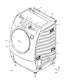
外槽20の槽後板22には、図3(a)に示すように、外槽20の外部に位置してドラムモータ24aが設けられている。このドラムモータ24aは、外槽20内に突出する図示しない回転軸を有するものであり、ドラムモータ24aの回転軸の前部には、図1に示すように、外槽20内に位置してドラム24が設けられている。ドラム24は、内部に洗濯物が収容可能な有底円筒状をなし、当該洗濯物の洗濯、すすぎ、乾燥に用いられるものであり、ドラム周板およびドラム後板を相互に接合することから構成されている。ドラム周板は前面および後面のそれぞれが開口する円筒状をなすものであり、ドラム後板はドラム周板の後面を閉鎖する円形状をなしている。このドラム24は、中心軸が外槽20の中心軸に重なるように配置され、当該ドラム24の中心軸を中心に回転可能に設けられ、ドラムモータ24aの運転状態のときにドラムモータ24aの回転軸と一体的に回転するものである。   The tank rear plate 22 of the outer tub 20 is provided with a drum motor 24a located outside the outer tub 20, as shown in FIG. The drum motor 24a has a rotating shaft (not shown) protruding into the outer tub 20, and is located in the outer tub 20 at the front of the rotating shaft of the drum motor 24a as shown in FIG. A drum 24 is provided. The drum 24 has a bottomed cylindrical shape that can accommodate laundry therein, and is used for washing, rinsing, and drying the laundry, and includes a drum peripheral plate and a drum rear plate that are joined to each other. Has been. The drum peripheral plate has a cylindrical shape in which each of the front surface and the rear surface is open, and the drum rear plate has a circular shape that closes the rear surface of the drum peripheral plate. The drum 24 is disposed so that the central axis thereof overlaps with the central axis of the outer tub 20, is provided to be rotatable around the central axis of the drum 24, and the drum motor 24a rotates when the drum motor 24a is in an operating state. It rotates integrally with the shaft.

ドラム24は、周壁であるドラム周板の全体に、図1に模式的に示すように、外槽20と連通するための多数の貫通孔24bを有している(図1では2箇所のみ図示)。これにより、ドラム24の内部空間は、多数の貫通孔24bのそれぞれを介して外槽20の内部空間と連通している。ドラム24のドラム周板のうち当該ドラム24の内周側には、図示しない複数のバッフルが固定されている。複数のバッフルは、ドラム24が回転することに応じてドラム24の中心軸を中心に円周方向へ移動するものである。これにより、ドラム24内の洗濯物は、複数のバッフルのそれぞれに引掛かりながら円周方向へ移動した後に重力で落下して撹拌されるようになる。   As schematically shown in FIG. 1, the drum 24 has a large number of through holes 24b for communicating with the outer tub 20 (only two places are shown in FIG. 1). ). Thereby, the internal space of the drum 24 communicates with the internal space of the outer tub 20 through each of the numerous through holes 24b. A plurality of baffles (not shown) are fixed to the inner peripheral side of the drum 24 in the drum peripheral plate of the drum 24. The plurality of baffles move in the circumferential direction around the central axis of the drum 24 as the drum 24 rotates. As a result, the laundry in the drum 24 moves in the circumferential direction while being hooked on each of the plurality of baffles, and then falls and is stirred by gravity.

前板2には、図2に示すように、扉25が設けられている。扉25は、閉鎖状態および開放状態相互間で作業者が操作することが可能なものである。扉25の閉鎖状態では扉25が外箱1の前板2に前方から接触し、扉25の開放状態では扉25が外箱1の前板2に対して前方へ離間する。外箱1の前板2には、図2に示すように、貫通孔状の出入口2aが形成されている。この出入口2aは、作業者が外槽20の前面の開口部およびドラム24の前面の開口部を通してドラム24内に対して洗濯物を出し入れするためのものであり、扉25の開放状態でドラム24内に対して洗濯物を出し入れすることが可能に開放され、扉25の閉鎖状態でドラム24内に対して洗濯物を出し入れすることが不能に閉鎖される。   As shown in FIG. 2, the front plate 2 is provided with a door 25. The door 25 can be operated by an operator between the closed state and the open state. When the door 25 is closed, the door 25 contacts the front plate 2 of the outer box 1 from the front, and when the door 25 is opened, the door 25 is separated forward from the front plate 2 of the outer box 1. As shown in FIG. 2, the front plate 2 of the outer box 1 is formed with a through-hole shaped entrance 2 a. The entrance 2a is used by an operator to put laundry into and out of the drum 24 through the opening on the front surface of the outer tub 20 and the opening on the front surface of the drum 24, and the drum 24 is opened when the door 25 is open. The laundry is opened so that the laundry can be taken in and out, and the door 25 is closed so that the laundry can be taken in and out of the drum 24 in a closed state.

外箱1内には、図示しないベローズが収納されている。ベローズは、扉25の閉鎖状態で外槽20の前面と扉25との間を気密状態にするものである。ベローズは、ゴム製であり、前後方向へ指向する筒状をなし、前端部が外箱1の前板2に出入口2aの周縁部で固定され、後端部が外槽20の槽周板21に固定されている。   A bellows (not shown) is accommodated in the outer box 1. The bellows is an airtight state between the front surface of the outer tub 20 and the door 25 when the door 25 is closed. The bellows is made of rubber and has a cylindrical shape directed in the front-rear direction. The front end is fixed to the front plate 2 of the outer box 1 at the peripheral edge of the entrance / exit 2a, and the rear end is a tank peripheral plate 21 of the outer tank 20. It is fixed to.

外箱1内には、外槽20に比べて高所に位置して給水弁26(図5参照)が設けられている。給水弁26は、入口および出口を有している。給水弁26の入口は水道の蛇口に接続され、給水弁26の出口は図示しない注水ケースに接続されている。注水ケースは、内部に洗剤などが収容されるものである。注水ケースの下端部には、外槽20まで延びている給水ホースが接続されている。この給水弁26は、図示しない給水弁モータを駆動源とするものであり、給水弁モータが回転操作されることに応じて閉鎖状態および開放状態相互間で切換えられる。この閉鎖状態とは、給水弁26が入口および出口のそれぞれが閉鎖された状態のことであり、開放状態とは、給水弁26の入口および出口のそれぞれが開放された状態である。給水弁26の開放状態では水道の蛇口から給水弁26、注水ケース、給水ホースを通して外槽20内に水道水が注入されるとともに、注水ケース内の洗剤なども外槽20内に供給されるようになる。   In the outer box 1, a water supply valve 26 (see FIG. 5) is provided at a higher position than the outer tub 20. The water supply valve 26 has an inlet and an outlet. The inlet of the water supply valve 26 is connected to a tap, and the outlet of the water supply valve 26 is connected to a water injection case (not shown). The water injection case contains a detergent or the like inside. A water supply hose extending to the outer tub 20 is connected to the lower end of the water injection case. The water supply valve 26 uses a water supply valve motor (not shown) as a drive source, and is switched between a closed state and an open state in response to the rotation operation of the water supply valve motor. This closed state is a state in which each of the inlet and outlet of the water supply valve 26 is closed, and the open state is a state in which each of the inlet and outlet of the water supply valve 26 is opened. In the open state of the water supply valve 26, tap water is injected into the outer tub 20 from the water tap through the water supply valve 26, the water supply case, and the water supply hose, and the detergent in the water supply case is also supplied into the outer tub 20. become.

外槽20の底部には、図示しない排水管の上端部が接続されており、排水管には排水弁27(図5参照)が介在されている。この排水弁27は、図示しない排水弁モータを駆動源とするものであり、排水弁モータが回転操作されることに応じて開放状態および閉鎖状態相互間で切換えられる。この排水弁27の閉鎖状態では給水弁26から外槽20内に注入された水道水が外槽20内に貯留され、排水弁27の開放状態では外槽20内の水道水が排水管の下端部を通して外槽20の外部に排出される。   An upper end of a drain pipe (not shown) is connected to the bottom of the outer tub 20, and a drain valve 27 (see FIG. 5) is interposed in the drain pipe. The drain valve 27 uses a drain valve motor (not shown) as a drive source, and is switched between an open state and a closed state in accordance with the rotation of the drain valve motor. When the drain valve 27 is closed, tap water injected into the outer tub 20 from the water supply valve 26 is stored in the outer tub 20, and when the drain valve 27 is open, tap water in the outer tub 20 is stored at the lower end of the drain pipe. It is discharged to the outside of the outer tub 20 through the section.

外箱1内には、図1、図3(a)および図4に示すように、外槽20と連結している入口および出口を有する循環ダクト28が収納されている。循環ダクト28は、排気ダクト29とリント捕獲ダクト30と中継ダクト31とメインダクト32とファンケーシング33と中継ダクト34と給気ダクト35とから構成されている。   As shown in FIGS. 1, 3 (a) and 4, a circulation duct 28 having an inlet and an outlet connected to the outer tub 20 is accommodated in the outer box 1. The circulation duct 28 includes an exhaust duct 29, a lint capturing duct 30, a relay duct 31, a main duct 32, a fan casing 33, a relay duct 34, and an air supply duct 35.

排気ダクト29は、図3(a)に示すように、外槽20の槽周板21の上方に配置され、上下方向へ指向する蛇腹状をなしている。排気ダクト29は、下端部に入口を有し、上端部に出口を有している。排気ダクト29の入口は、外槽20の槽周板21の前端部と連結している。   As shown in FIG. 3A, the exhaust duct 29 is disposed above the tank peripheral plate 21 of the outer tank 20 and has a bellows shape directed in the vertical direction. The exhaust duct 29 has an inlet at the lower end and an outlet at the upper end. The inlet of the exhaust duct 29 is connected to the front end of the tank peripheral plate 21 of the outer tank 20.

リント捕獲ダクト30は、外槽20の槽周板21の上方に配置され、前後方向へ指向する通路状をなしている。リント捕獲ダクト30は、前端部に入口を有し、後端部に出口を有している。リント捕獲ダクト30の入口は、排気ダクト29の出口と連結している。   The lint capturing duct 30 is disposed above the tank peripheral plate 21 of the outer tank 20 and has a passage shape oriented in the front-rear direction. The lint capture duct 30 has an inlet at the front end and an outlet at the rear end. The inlet of the lint capturing duct 30 is connected to the outlet of the exhaust duct 29.

中継ダクト31は、外槽20の槽後板22の後方に配置され、槽後板22に後方から空気が通過可能な大きさの隙間を介して対向している。中継ダクト31は、上下方向へ指向する通路状をなすものである。中継ダクト31は、上端部に入口を有し、下端部に出口を有している。中継ダクト31の入口は、リント捕獲ダクト30の出口に連結している。   The relay duct 31 is disposed behind the tank rear plate 22 of the outer tank 20, and faces the tank rear plate 22 via a gap having a size that allows air to pass from the rear. The relay duct 31 has a path shape oriented in the vertical direction. The relay duct 31 has an inlet at the upper end and an outlet at the lower end. The entrance of the relay duct 31 is connected to the exit of the lint capturing duct 30.

メインダクト32は、図3(a)および図4に示すように、底板7の主底板部14の後端部に固定され、外箱1内の後端部に配置されている。メインダクト32は、左右方向へ指向する通路状をなすものであり、右端部に入口を有し、左端部に出口を有している。メインダクト32の入口は、中継ダクト31の出口と連結している。   As shown in FIGS. 3A and 4, the main duct 32 is fixed to the rear end portion of the main bottom plate portion 14 of the bottom plate 7 and is disposed at the rear end portion in the outer box 1. The main duct 32 has a channel shape directed in the left-right direction, and has an inlet at the right end and an outlet at the left end. The inlet of the main duct 32 is connected to the outlet of the relay duct 31.

ファンケーシング33は、メインダクト32の左端部に固定されている。ファンケーシング33は、貫通孔状の入口および筒状の出口を有している。ファンケーシング33の入口は、メインダクト32の出口と連結している。   The fan casing 33 is fixed to the left end portion of the main duct 32. The fan casing 33 has a through-hole shaped inlet and a cylindrical outlet. The inlet of the fan casing 33 is connected to the outlet of the main duct 32.

中継ダクト34は、図3(a)に示すように、外槽20の槽後板22の後方に配置され、槽後板22に後方から空気が通過可能な大きさの隙間を介して対向している。中継ダクト34は、上下方向へ指向する蛇腹状をなし、下端部に入口を有し、上端部に出口を有している。中継ダクト34の入口は、ファンケーシング33の出口と連結している。   As shown in FIG. 3A, the relay duct 34 is disposed behind the tank rear plate 22 of the outer tank 20, and faces the tank rear plate 22 through a gap that allows air to pass from the rear. ing. The relay duct 34 has a bellows shape that is directed in the vertical direction, has an inlet at the lower end, and has an outlet at the upper end. The entrance of the relay duct 34 is connected to the exit of the fan casing 33.

給気ダクト35は、外槽20の槽後板22に固定され、槽後板22の後方に配置されている。給気ダクト35は、下端部に入口を有し、上端部に出口を有している。給気ダクト35の入口は、中継ダクト34の出口と連結している。また、給気ダクト35の出口は、外槽20の槽後板22の上端部と連結している。ここで、排気ダクト29の入口が循環ダクト28の入口に相当し、給気ダクト35の出口が循環ダクト28の出口に相当する。   The air supply duct 35 is fixed to the tank rear plate 22 of the outer tank 20 and is disposed behind the tank rear plate 22. The air supply duct 35 has an inlet at the lower end and an outlet at the upper end. The inlet of the air supply duct 35 is connected to the outlet of the relay duct 34. The outlet of the air supply duct 35 is connected to the upper end portion of the tank rear plate 22 of the outer tank 20. Here, the inlet of the exhaust duct 29 corresponds to the inlet of the circulation duct 28, and the outlet of the air supply duct 35 corresponds to the outlet of the circulation duct 28.

ファンケーシング33には、図1および図4に示すように、ファンモータ36が固定されている。ファンモータ36は、ファンケーシング33の外部に配置されたものであり、図1に示すように、ファンケーシング33の内部に突出する回転軸36aを有している。ファンモータ36の回転軸36aの先端部には、ファンケーシング33内に位置してファン37が設けられている。この構成により、ファンモータ36の運転状態でファン37が回転することにより、外槽20内の空気は、循環ダクト28の排気ダクト29とリント捕獲ダクト30と中継ダクト31とメインダクト32とファンケーシング33と中継ダクト34と給気ダクト35とを、この順に通って外槽20内に戻るようになる。ここで、ファンモータ36およびファン37が外槽20内の空気を循環ダクト28の入口から当該循環ダクト28内を通し出口から外槽20内へ戻して当該空気の循環を行う送風機38に相当する。この送風機38による循環ダクト28内の空気の流れを、図1の破線の矢印で示す。   As shown in FIGS. 1 and 4, a fan motor 36 is fixed to the fan casing 33. The fan motor 36 is disposed outside the fan casing 33, and has a rotating shaft 36 a that protrudes inside the fan casing 33 as shown in FIG. 1. A fan 37 is provided at the tip of the rotation shaft 36 a of the fan motor 36 so as to be located in the fan casing 33. With this configuration, when the fan 37 rotates in the operation state of the fan motor 36, the air in the outer tub 20 is discharged from the exhaust duct 29 of the circulation duct 28, the lint capturing duct 30, the relay duct 31, the main duct 32, and the fan casing. 33, the relay duct 34, and the air supply duct 35 are returned to the inside of the outer tub 20 through this order. Here, the fan motor 36 and the fan 37 correspond to the blower 38 that circulates the air by passing the air in the outer tub 20 from the inlet of the circulation duct 28 through the circulation duct 28 and from the outlet to the outer tub 20. . The flow of air in the circulation duct 28 by the blower 38 is indicated by the broken-line arrows in FIG.

送風機38の機種は、上述の循環させる空気の量、循環速度などによって適宜選択される。例えば、ドラム24の容量が大きいほど、外槽20、ドラム24および循環ダクト28内を循環する空気の量も多くなるため、風量が大きい送風機38が用いられる。例えば、洗濯物の質量が4kgである場合、送風機38として、ファン37の回転数の定格の最大値が5500rpm、通常の運転時すなわち乾燥行程時の回転数が4500rpm、風量が0.05kg/s、風速が12m/sの出力のものが用いられる。   The type of the blower 38 is appropriately selected according to the amount of air to be circulated, the circulation speed, and the like. For example, the larger the capacity of the drum 24, the greater the amount of air that circulates in the outer tub 20, the drum 24, and the circulation duct 28. For example, when the mass of the laundry is 4 kg, as the blower 38, the rated maximum value of the rotation speed of the fan 37 is 5500 rpm, the rotation speed during normal operation, that is, the drying process is 4500 rpm, and the air volume is 0.05 kg / s. A wind speed of 12 m / s is used.

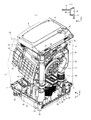
外箱1内には、図1に示すように、コンプレッサ39、電子膨張弁40、サクションパイプ41およびアキムレータ42が収容されている。また、循環ダクト28のうちメインダクト32内には、図1および図3(a)に示すようにコンデンサ43およびエバポレータ44が収容されている。   As shown in FIG. 1, a compressor 39, an electronic expansion valve 40, a suction pipe 41 and an accumulator 42 are accommodated in the outer box 1. Further, in the main duct 32 of the circulation duct 28, a capacitor 43 and an evaporator 44 are accommodated as shown in FIGS.

コンプレッサ39は、冷媒をコンデンサ43およびエバポレータ44に供給するものであり、例えばロータリ型のものであり、冷媒を吐出する吐出口および冷媒を吸込む吸込口を有している。コンプレッサ39は、図示しないコンプケースに収容されているコンプモータ39a(図1および図5参照)の回転数によって出力が変わるものであり、例えば、通常の運転時では50Hzの出力で駆動していた場合に、必要に応じて定格で駆動可能な範囲のうちの最小値すなわち下限値である40Hzの出力で駆動することが可能なものである。すなわち、コンプレッサ39は、図示しないインバータの電源からの電力に応じて出力が変更可能であり、例えば、インバータ電源からコンプモータ39aに供給される電力が小さくなるほど、コンプモータ39aの周波数、すなわち回転数は小さくなってコンプレッサ39の出力が小さくなり、コンプレッサ39からコンデンサ43およびエバポレータ44に供給される冷媒の供給量は少なくなる。   The compressor 39 supplies refrigerant to the condenser 43 and the evaporator 44, and is, for example, a rotary type, and has a discharge port for discharging the refrigerant and a suction port for sucking the refrigerant. The output of the compressor 39 changes depending on the rotational speed of a comp motor 39a (see FIGS. 1 and 5) housed in a not-shown comp case. For example, the compressor 39 is driven at an output of 50 Hz during normal operation. In some cases, it is possible to drive with an output of 40 Hz, which is the minimum value, that is, the lower limit value of the range that can be driven with a rating as required. That is, the output of the compressor 39 can be changed according to the power from the power source of the inverter (not shown). Becomes smaller, the output of the compressor 39 becomes smaller, and the amount of refrigerant supplied from the compressor 39 to the condenser 43 and the evaporator 44 becomes smaller.

コンデンサ43およびエバポレータ44のそれぞれは、冷媒管の表面に複数のフィンを接合してなるものである。コンデンサ43の冷媒管の入口は、図1に示すように、コンプレッサ39の吐出口に接続されている。エバポレータ44の冷媒管の入口は、電子膨張弁40を介してコンデンサ43の冷媒管の出口に接続されている。エバポレータ44の冷媒管の出口は、サクションパイプ41およびアキムレータ42を介してコンプレッサ39の吸込口に接続されている。コンプレッサ39のコンプモータ39aの運転状態ではコンプレッサ39の吐出口から吐出された冷媒は、コンデンサ43の冷媒管、電子膨張弁40、エバポレータ44の冷媒管、サクションパイプ41およびアキムレータ42を、この順に通ってコンプレッサ39の吸込口に戻る。なお、図示はしないが、コンプレッサ39、コンデンサ43、電子膨張弁40、エバポレータ44、サクションパイプ41、アキムレータ42の各間には、冷媒が通る冷媒用パイプ(図示せず)が設けられ、冷媒がこの順で流れる冷凍サイクルが構成される。また、図1において、冷凍サイクルにおける冷媒の流れを実線の矢印で示す。   Each of the condenser 43 and the evaporator 44 is formed by joining a plurality of fins to the surface of the refrigerant pipe. The inlet of the refrigerant pipe of the condenser 43 is connected to the outlet of the compressor 39 as shown in FIG. The inlet of the refrigerant pipe of the evaporator 44 is connected to the outlet of the refrigerant pipe of the condenser 43 via the electronic expansion valve 40. The outlet of the refrigerant pipe of the evaporator 44 is connected to the suction port of the compressor 39 via the suction pipe 41 and the accumulator 42. In the operating state of the compressor motor 39a of the compressor 39, the refrigerant discharged from the discharge port of the compressor 39 passes through the refrigerant pipe of the condenser 43, the electronic expansion valve 40, the refrigerant pipe of the evaporator 44, the suction pipe 41 and the accumulator 42 in this order. Return to the suction port of the compressor 39. Although not shown, a refrigerant pipe (not shown) through which a refrigerant passes is provided between the compressor 39, the condenser 43, the electronic expansion valve 40, the evaporator 44, the suction pipe 41, and the accumulator 42. A refrigeration cycle that flows in this order is configured. Moreover, in FIG. 1, the flow of the refrigerant | coolant in a refrigerating cycle is shown by the solid line arrow.

ここで、コンデンサ43は、循環ダクト28内のうちコンデンサ43を通過する空気を加熱するためのものであり、図1に示すように、エバポレータ44よりも循環ダクト28のメインダクト32の出口側、すなわちエバポレータ44に比べて送風機38のファンモータ36の運転状態での空気の流れの下流側に配置されている。エバポレータ44は、循環ダクト28内のうちエバポレータを通る空気を冷却するものであり、コンデンサ43よりもメインダクト32の入口側すなわち空気の循環において上流側に配置されている。これにより、外槽20から循環ダクト28に流れてくる空気は、コンデンサ43よりも先にエバポレータ44に接触する構成となる。   Here, the condenser 43 is for heating the air passing through the condenser 43 in the circulation duct 28, and as shown in FIG. 1, the outlet side of the main duct 32 of the circulation duct 28 rather than the evaporator 44, That is, it is arranged on the downstream side of the air flow in the operation state of the fan motor 36 of the blower 38 as compared to the evaporator 44. The evaporator 44 cools the air passing through the evaporator in the circulation duct 28, and is disposed on the inlet side of the main duct 32, that is, on the upstream side in the circulation of air from the condenser 43. Accordingly, the air flowing from the outer tub 20 to the circulation duct 28 comes into contact with the evaporator 44 before the condenser 43.

この構成によれば、後で詳述するが、送風機38のファンモータ36およびコンプレッサ39のコンプモータ39aのそれぞれの運転状態では外槽20内から流れてくる空気が循環ダクト28のメインダクト32内でエバポレータ44に接触することで除湿および冷却され、この除湿された空気がメインダクト32内でコンデンサ43に接触することで加熱される。即ち、ドラム24内の洗濯物の乾燥を行う際において当該ドラム24内に水分を含んだ未乾燥の洗濯物が収容されている場合には、エバポレータ44が空気を冷却することで空気から湿気を減らして除湿を行い、コンデンサ43が所定温度まで空気を加熱するので、外槽20内に低湿度で所定温度の空気が供給される。これにより、ドラム24内の洗濯物の乾燥が行われる。   According to this configuration, as will be described in detail later, air flowing from the outer tub 20 in the main duct 32 of the circulation duct 28 in the respective operating states of the fan motor 36 of the blower 38 and the compressor motor 39a of the compressor 39. Then, the air is dehumidified and cooled by contacting the evaporator 44, and the dehumidified air is heated by contacting the condenser 43 in the main duct 32. That is, when the laundry in the drum 24 is dried and the undried laundry containing moisture is stored in the drum 24, the evaporator 44 cools the air to remove moisture from the air. The dehumidification is carried out and the condenser 43 heats the air to a predetermined temperature, so that air at a predetermined temperature is supplied into the outer tub 20 at a low humidity. Thereby, the laundry in the drum 24 is dried.

電子膨張弁40は、図示しない電子膨張弁モータを駆動源とするものであり、後述する制御手段をなす制御装置45によって弁の開閉度合いが調整されるものである。例えば、エバポレータ44の入口の温度と出口の温度との差が所定温度に達したとき、すなわち、冷媒の液体がコンプレッサ39内に流入するリキッドバッグが生じる前に、制御装置45は、電子膨張弁40を流れる冷媒の量が減るように当該電子膨張弁40の開閉度合いを調整する。   The electronic expansion valve 40 uses an electronic expansion valve motor (not shown) as a drive source, and the degree of opening and closing of the valve is adjusted by a control device 45 serving as a control means described later. For example, when the difference between the inlet temperature and the outlet temperature of the evaporator 44 reaches a predetermined temperature, that is, before the liquid bag in which the refrigerant liquid flows into the compressor 39 is generated, the control device 45 is connected to the electronic expansion valve. The degree of opening and closing of the electronic expansion valve 40 is adjusted so that the amount of the refrigerant flowing through 40 decreases.

メインダクト32の側壁であってコンデンサ43およびエバポレータ44の間の側壁の一部、例えば図4に示すメインダクト32の天井板46には、図1および図4に示すように、ダクト吸気口47が形成されている。ダクト吸気口47は、ファンモータ36の運転状態でのメインダクト32内の空気の流れに対して直交する方向に沿って配列された複数の貫通孔からなるものである。また、メインダクト32の側壁であって外槽20の出口およびエバポレータ44の間の側壁の一部、即ちエバポレータ44に比べて空気の流れの上流側には、ダクト排気口48が形成されている。ダクト排気口48は、ファンモータ36の運転状態でのメインダクト32内の空気の流れに対して直交する方向に沿って配列された複数の貫通孔からなるものである。この構成により、循環ダクト28内を流れる空気の一部がダクト排気口48から排出されるとともに、ダクト吸気口47から新たな空気が循環ダクト28内に供給されるようになる。ダクト排気口48から排気された空気は、外箱1の後板5に沿って上昇し、左外箱排気口17および右外箱排気口19のそれぞれから外箱1の外部に排出される。また、ダクト吸気口47から給気される空気は、外箱1の外部の空気が底板7の下方の隙間および底板7の外箱吸気口23のそれぞれから供給される。   A part of the side wall of the main duct 32 between the condenser 43 and the evaporator 44, for example, the ceiling plate 46 of the main duct 32 shown in FIG. Is formed. The duct intake port 47 is composed of a plurality of through holes arranged along a direction orthogonal to the air flow in the main duct 32 when the fan motor 36 is in operation. Further, a duct exhaust port 48 is formed on the side wall of the main duct 32 and a part of the side wall between the outlet of the outer tub 20 and the evaporator 44, that is, on the upstream side of the air flow compared to the evaporator 44. . The duct exhaust port 48 includes a plurality of through holes arranged along a direction orthogonal to the air flow in the main duct 32 when the fan motor 36 is in operation. With this configuration, a part of the air flowing in the circulation duct 28 is discharged from the duct exhaust port 48, and new air is supplied from the duct intake port 47 into the circulation duct 28. The air exhausted from the duct exhaust port 48 rises along the rear plate 5 of the outer box 1 and is discharged from the left outer box exhaust port 17 and the right outer box exhaust port 19 to the outside of the outer box 1. Further, the air supplied from the duct inlet 47 is supplied from the outside of the outer casing 1 through the gap below the bottom plate 7 and the outer casing inlet 23 of the bottom plate 7.

冷媒用パイプの外周表面であってコンプレッサ39の吐出口側には、コンプ吐出側温度センサ51が設けられている。コンプ吐出側温度センサ51は、コンプレッサ39から吐出される冷媒の温度を測定するものである。また、コンデンサ43の表面には、コンデンサ用温度センサ52が設けられている。コンデンサ用温度センサ52は、コンデンサ43の表面温度を測定するものである。さらに、冷媒用パイプの外周表面であってエバポレータ44の冷媒管の入口側には、エバ入口側温度センサ53が設けられている。エバ入口側温度センサ53は、エバポレータ44に供給される冷媒の温度を測定するものである。そして、エバポレータ44の冷媒管の出口側には、エバ出口側温度センサ54が設けられている。エバ出口側温度センサ54は、エバポレータ44から吐出される冷媒の温度を測定するものである。   A compressor discharge side temperature sensor 51 is provided on the outer peripheral surface of the refrigerant pipe and on the discharge port side of the compressor 39. The compressor discharge side temperature sensor 51 measures the temperature of the refrigerant discharged from the compressor 39. A capacitor temperature sensor 52 is provided on the surface of the capacitor 43. The capacitor temperature sensor 52 measures the surface temperature of the capacitor 43. Further, an evaporator inlet side temperature sensor 53 is provided on the outer peripheral surface of the refrigerant pipe and on the inlet side of the refrigerant pipe of the evaporator 44. The evaporator inlet side temperature sensor 53 measures the temperature of the refrigerant supplied to the evaporator 44. An evaporator outlet side temperature sensor 54 is provided on the outlet side of the refrigerant pipe of the evaporator 44. The evaporator outlet side temperature sensor 54 measures the temperature of the refrigerant discharged from the evaporator 44.

循環ダクト28内にあって空気の流れにおけるエバポレータ44の上流側、例えば外槽20の出口とエバポレータ44との間、より詳しくはダクト排気口48とエバポレータ44との間には、ドラム出口側温度センサ55が設けられている。ドラム出口側温度センサ55は、循環ダクト28内を流れる空気のうち外槽20内すなわちドラム24内から供給される空気の温度を測定するものである。さらに、循環ダクト28内の空気の流れにおいてコンデンサ43の下流側、例えば送風機38のファン37と外槽20の入口との間には、ドラム入口側温度センサ56が設けられている。ドラム入口側温度センサ56は、循環ダクト28内を流れる空気のうち外槽20内すなわちドラム24内に入る空気の温度を測定するものである。   In the circulation duct 28, the upstream side of the evaporator 44 in the air flow, for example, between the outlet of the outer tub 20 and the evaporator 44, more specifically, between the duct exhaust port 48 and the evaporator 44, the drum outlet side temperature. A sensor 55 is provided. The drum outlet side temperature sensor 55 measures the temperature of the air supplied from the inside of the outer tub 20, that is, the drum 24, out of the air flowing through the circulation duct 28. Furthermore, a drum inlet side temperature sensor 56 is provided downstream of the condenser 43 in the air flow in the circulation duct 28, for example, between the fan 37 of the blower 38 and the inlet of the outer tub 20. The drum inlet side temperature sensor 56 measures the temperature of the air flowing in the circulation duct 28 and entering the outer tub 20, that is, the drum 24.

外箱1の前板2には、図2に示すように、操作パネル57が設けられている。操作パネル57は、スタートスイッチ57aなどのスイッチおよび表示部57bを有している。また、本実施形態の操作パネル57は、後述する「しわ伸ばし」のスイッチ57cを有している。
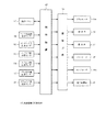
操作パネル57の裏側には上述した制御装置45が設けられている。図5にも示す制御装置45は、例えばマイクロコンピュータからなるものであり、洗濯乾燥機の作動全般、例えば、洗い、脱水、乾燥の各種運転の制御をするものである。すなわち、この制御装置45は、操作パネル57からの信号、コンプ吐出側温度センサ51からの信号、コンデンサ用温度センサ52からの信号、エバ入口側温度センサ53からの信号、エバ出口側温度センサ54からの信号、ドラム出口側温度センサ55からの信号、ドラム入口側温度センサ56からの信号、その他の図示しない入力手段からの信号に基づき、更にあらかじめ記憶した制御プログラムに基づいて、駆動回路58を介して、ドラムモータ24a、給水弁26、排水弁27、送風機38のファンモータ36、コンプレッサ39のコンプモータ39a、電子膨張弁40の開閉度合いなどを制御し、操作された操作内容に対応した表示を操作パネル57の表示部57bに表示する制御も行うものである。
The front panel 2 of the outer box 1 is provided with an operation panel 57 as shown in FIG. The operation panel 57 includes a switch such as a start switch 57a and a display unit 57b. In addition, the operation panel 57 of the present embodiment includes a “wrinkle stretching” switch 57c described later.
The control device 45 described above is provided on the back side of the operation panel 57. The control device 45 shown in FIG. 5 is composed of, for example, a microcomputer, and controls the overall operation of the washing and drying machine, for example, various operations such as washing, dehydration, and drying. That is, the control device 45 includes a signal from the operation panel 57, a signal from the compressor discharge side temperature sensor 51, a signal from the capacitor temperature sensor 52, a signal from the evaporator inlet side temperature sensor 53, and an evaporator outlet side temperature sensor 54. On the basis of a control program stored in advance based on a signal from the drum, a signal from the drum outlet temperature sensor 55, a signal from the drum inlet temperature sensor 56, a signal from other input means (not shown), and the like. Via the drum motor 24a, the water supply valve 26, the drain valve 27, the fan motor 36 of the blower 38, the compressor motor 39a of the compressor 39, the degree of opening and closing of the electronic expansion valve 40, etc., and the display corresponding to the operated content Is also displayed on the display unit 57b of the operation panel 57.

具体的には、制御装置45は、洗濯物の乾燥時に、コンプ吐出側温度センサ51からの信号に基づきコンプレッサ39から吐出される冷媒の温度が所定温度以上になったと判断した場合、コンプレッサ39のコンプモータ39aの回転数を下げて、コンプレッサ39の出力を小さく、例えば下限値の出力で駆動するように制御を行う。これにより、コンデンサ43に流れる冷媒の温度は低くなり、コンデンサ43の温度が高くなることが抑制される。   Specifically, when the control device 45 determines that the temperature of the refrigerant discharged from the compressor 39 is equal to or higher than a predetermined temperature based on a signal from the compressor discharge side temperature sensor 51 when the laundry is dried, Control is performed such that the rotational speed of the compressor motor 39a is lowered to reduce the output of the compressor 39, for example, to drive with a lower limit value output. As a result, the temperature of the refrigerant flowing through the capacitor 43 is lowered, and the temperature of the capacitor 43 is suppressed from increasing.

また、制御装置45は、洗濯物の洗い、脱水、乾燥の洗濯運転時に、コンデンサ用温度センサ52からの信号に基づきコンデンサ43の表面温度が所定温度以上になったと判断した場合、コンプレッサ39のコンプモータ39aの回転数を下げて、コンプレッサ39の出力を小さく、例えば下限値の出力で駆動するように制御を行う。これにより、コンデンサ43に流れる冷媒の温度は低くなり、コンデンサ43の温度が高くなることが抑制される。   Further, when the controller 45 determines that the surface temperature of the capacitor 43 has become equal to or higher than a predetermined temperature based on a signal from the capacitor temperature sensor 52 during the washing, dehydrating and drying washing operations, Control is performed such that the rotational speed of the motor 39a is decreased to reduce the output of the compressor 39, for example, to drive at a lower limit output. As a result, the temperature of the refrigerant flowing through the capacitor 43 is lowered, and the temperature of the capacitor 43 is suppressed from increasing.

また、制御装置45は、洗濯物の洗い、脱水、乾燥の洗濯運転時に、SH制御(スーパーヒート制御)を行っている。すなわち、制御装置45は、洗濯物の洗い、脱水、乾燥の洗濯運転時に、エバ入口側温度センサ53からの信号およびエバ出口側温度センサ54からの信号に基づき、エバポレータ44に供給される冷媒の温度とエバポレータ44から吐出される冷媒の温度との差が所定温度に達したと判断した場合、上述したように当該電子膨張弁40を流れる冷媒の量が減るように当該電子膨張弁40の開閉度合いを調整し、必要に応じてコンプレッサ39の駆動を適宜停止する制御を行っている。これにより、リキッドバッグの発生が抑制される。   The control device 45 performs SH control (superheat control) during laundry washing, dehydration and drying washing operations. That is, the control device 45 determines the refrigerant to be supplied to the evaporator 44 based on the signal from the evaporator inlet side temperature sensor 53 and the signal from the evaporator outlet side temperature sensor 54 during the washing operation of washing, dehydrating and drying. When it is determined that the difference between the temperature and the temperature of the refrigerant discharged from the evaporator 44 has reached a predetermined temperature, the electronic expansion valve 40 is opened and closed so that the amount of refrigerant flowing through the electronic expansion valve 40 decreases as described above. Control is performed to adjust the degree and appropriately stop driving of the compressor 39 as necessary. Thereby, generation | occurrence | production of a liquid bag is suppressed.

また、制御装置45は、洗濯物の乾燥時に、ドラム出口側温度センサ55からの信号およびドラム入口側温度センサ56からの信号に基づき、ドラム24から流れる空気の温度とドラム24に入る空気の温度との差が所定温度に達した場合、洗濯物の乾燥が終了したと判断し、一定時間経過後に乾燥の制御を終了する。   The controller 45 also controls the temperature of the air flowing from the drum 24 and the temperature of the air entering the drum 24 based on the signal from the drum outlet side temperature sensor 55 and the signal from the drum inlet side temperature sensor 56 when the laundry is dried. When the temperature difference reaches a predetermined temperature, it is determined that the laundry has been dried, and the drying control is terminated after a predetermined time.

次に、本実施形態の作用および効果について説明する。
作業者がスタートスイッチ57aを操作した場合、制御装置45は例えば、洗濯運転の標準コースを開始する。この標準コースは、洗い行程とすすぎ行程と脱水行程と乾燥行程のそれぞれを順に行うものである。
洗い行程は、外槽20内に水を貯留した状態でドラム24を回転操作することでドラム24内の洗濯物を水で洗う行程である。
すすぎ行程は、外槽20内に水を貯留した状態でドラム24を回転操作することでドラム24内の洗濯物を水ですすぐ行程である。脱水行程は、ドラム24を回転操作することでドラム24内の洗濯物から水分を遠心力で排出する行程である。
Next, the operation and effect of this embodiment will be described.
When the operator operates the start switch 57a, the control device 45 starts a standard course of the washing operation, for example. In this standard course, a washing process, a rinsing process, a dehydrating process, and a drying process are sequentially performed.
The washing process is a process of washing the laundry in the drum 24 with water by rotating the drum 24 in a state where water is stored in the outer tub 20.
The rinsing process is a process of rinsing the laundry in the drum 24 with water by rotating the drum 24 in a state where water is stored in the outer tub 20. The dehydration process is a process in which moisture is discharged from the laundry in the drum 24 by centrifugal force by rotating the drum 24.

乾燥行程は、送風機38のファンモータ36およびコンプレッサ39のコンプモータ39aのそれぞれを運転状態とすることでドラム24内の洗濯物を風で乾かす行程である。具体的には、制御装置45は、コンプモータ39aを駆動して、冷媒をコンデンサ43、電子膨張弁40、エバポレータ44に供給してなる冷凍サイクルを実行させる。そして、制御装置45は、ファンモータ36を駆動してファン37を回転させ、外槽20内すなわちドラム24内の空気を循環ダクト28の入口から当該循環ダクト28内を通し出口から外槽20内へ戻し当該空気の循環を行わせる。これにより、外槽20内のドラム24に収容されている洗濯物によって水分、湿気を多く含む空気は、ドラム24の貫通孔24bを通って当該外槽20から循環ダクト28に流される。外槽20から出た空気の一部はダクト排気口48から排出されるとともに、残りの空気はエバポレータ44を通る。エバポレータ44を通る空気は、当該エバポレータ44によって除湿、冷却される。除湿された空気はコンデンサ43を通る。また、このとき、ダクト吸気口47から空気が循環ダクト28内に供給され、循環ダクト28内に供給された空気もコンデンサ43を通る。これらコンデンサ43を通る空気は、当該コンデンサ43によって加熱される。そして、コンデンサ43を通った空気は、送風機38の送風作用によって外槽20内に供給され、ドラム24の貫通孔24bから当該ドラム24内に供給される。その結果、エバポレータ44で除湿されコンデンサ43で加熱された空気がドラム24内の洗濯物に当たるようになり、当該洗濯物は乾燥される。この場合、貫通孔24bがドラム24の周壁に多数形成され、当該貫通孔24bから空気がドラム24に供給される構成であるので、ドラム24に供給される空気が洗濯物をドラム24の周壁に押圧しにくく、洗濯物のしわの発生が低減される。   The drying process is a process of drying the laundry in the drum 24 with wind by setting each of the fan motor 36 of the blower 38 and the compressor motor 39a of the compressor 39 to the operating state. Specifically, the control device 45 drives the compressor motor 39a to execute a refrigeration cycle in which the refrigerant is supplied to the capacitor 43, the electronic expansion valve 40, and the evaporator 44. Then, the control device 45 drives the fan motor 36 to rotate the fan 37, and passes the air in the outer tub 20, that is, the drum 24 from the inlet of the circulation duct 28 through the circulation duct 28 and from the outlet to the inside of the outer tub 20. Return to return to the air circulation. As a result, air containing a large amount of moisture and moisture by the laundry stored in the drum 24 in the outer tub 20 flows from the outer tub 20 to the circulation duct 28 through the through holes 24 b of the drum 24. Part of the air exiting the outer tub 20 is discharged from the duct exhaust port 48, and the remaining air passes through the evaporator 44. The air passing through the evaporator 44 is dehumidified and cooled by the evaporator 44. The dehumidified air passes through the condenser 43. At this time, air is supplied from the duct inlet 47 into the circulation duct 28, and the air supplied into the circulation duct 28 also passes through the condenser 43. The air passing through these capacitors 43 is heated by the capacitors 43. The air that has passed through the condenser 43 is supplied into the outer tub 20 by the blowing action of the blower 38, and is supplied into the drum 24 from the through hole 24 b of the drum 24. As a result, the air dehumidified by the evaporator 44 and heated by the condenser 43 comes into contact with the laundry in the drum 24, and the laundry is dried. In this case, a large number of through holes 24 b are formed in the peripheral wall of the drum 24, and air is supplied from the through holes 24 b to the drum 24. Therefore, the air supplied to the drum 24 causes the laundry to enter the peripheral wall of the drum 24. It is difficult to press and the occurrence of wrinkles in the laundry is reduced.

乾燥行程では、乾燥行程の前半の時間においてドラム24が一方向に30秒回転し、次に反対方向に30秒回転する動作が繰り返し行われ、乾燥行程の後半の時間においてもドラム24が一方向に30秒回転し、次に反対方向に30秒回転する動作が繰り返し行われる。   In the drying process, the drum 24 rotates in one direction for 30 seconds in the first half of the drying process and then rotates in the opposite direction for 30 seconds. The drum 24 moves in one direction in the latter half of the drying process. For 30 seconds and then for 30 seconds in the opposite direction is repeated.

ここで、作業者が洗濯運転の乾燥行程が行われる前、あるいは乾燥行程のみを行う際に「しわ伸ばし」のスイッチ57cを押圧操作すると、制御装置45は、乾燥行程として「しわ伸ばし」行程を実行する。「しわ伸ばし」行程では、制御装置45は、コンプレッサ39のコンプモータ39aを外槽20内に入る空気の温度が65℃以下となり且つエバポレータ44の入口の温度が30℃以下となる予め決められた出力で駆動する制御を行う。このコンプレッサ39の出力は、ドラム24などの大きさ、洗濯物の量によって異なり、予め試験によって求められている。すなわち、制御装置45は、コンプモータ39aに供給する電力の大きさを制御することにより、通常の乾燥行程でのコンプレッサ39の出力が定格の例えば50Hzである場合に、「しわ伸ばし」行程ではコンプレッサ39の出力を定格の下限値である例えば40Hzでコンプレッサ39を駆動することにより、上記した空気の温度が65℃以下となり且つエバポレータ44の入口の温度が30℃以下となる。これは、コンプレッサ39の出力を下げることにより、コンデンサ43に流れる高温の冷媒の供給量が少なくなり、コンデンサ43が加熱されにくくなるためである。また、エバポレータ44の入口の温度が30℃温度以下に低下するのは、コンプレッサ39の出力、電子膨張弁40の開閉度合いを調整してエバポレータ44に流れる冷媒の量を所定量、すなわちエバポレータ44の入口の温度が30℃以下となる量の冷媒がエバポレータ44に供給されるためである。この実施形態では、エバポレータ44に供給される冷媒の量は主にコンプレッサ39の出力で調整され、例えばコンプレッサ39の出力を定格の下限値以上で駆動することにより、冷媒の供給量が調整される。   Here, when the operator presses the “wrinkle stretching” switch 57c before the drying process of the washing operation is performed or when only the drying process is performed, the control device 45 performs the “wrinkle stretching” process as the drying process. Execute. In the “wrinkle stretching” process, the control device 45 determines in advance that the temperature of the air that enters the outer motor 20 through the compressor motor 39a of the compressor 39 is 65 ° C. or lower and the temperature of the inlet of the evaporator 44 is 30 ° C. or lower. Control driven by output. The output of the compressor 39 differs depending on the size of the drum 24 and the like and the amount of laundry, and is obtained in advance by a test. That is, the control device 45 controls the magnitude of the electric power supplied to the compressor motor 39a, so that when the output of the compressor 39 in the normal drying process is rated, for example, 50 Hz, the compressor in the “wrinkle stretching” process. By driving the compressor 39 with the output of 39 at a rated lower limit value of 40 Hz, for example, the temperature of the air is 65 ° C. or lower and the temperature of the inlet of the evaporator 44 is 30 ° C. or lower. This is because by reducing the output of the compressor 39, the supply amount of the high-temperature refrigerant flowing to the condenser 43 is reduced, and the condenser 43 is hardly heated. Further, the temperature at the inlet of the evaporator 44 decreases to a temperature of 30 ° C. or lower because the amount of refrigerant flowing into the evaporator 44 is adjusted by adjusting the output of the compressor 39 and the degree of opening and closing of the electronic expansion valve 40, that is, the evaporator 44 This is because the refrigerant is supplied to the evaporator 44 in such an amount that the inlet temperature is 30 ° C. or lower. In this embodiment, the amount of refrigerant supplied to the evaporator 44 is mainly adjusted by the output of the compressor 39. For example, the refrigerant supply amount is adjusted by driving the output of the compressor 39 at a rated lower limit value or more. .

さらに、制御装置45は、送風機38をファン37の回転数が定格の最大値となる出力で駆動する制御を行う。すなわち、制御装置45は、送風機38を仕様書などで定める定格の範囲のうち最大の回転数、言い換えると送風機38が寿命になるまで連続運転可能な最大の回転数で駆動する。例えば、制御装置45は、上述したように、洗濯物の質量が4kgである場合、ファン37の回転数が5500rpmとなるように送風機38を制御する。なお、制御装置45は、必要に応じて、外槽20内に入る空気の温度が65℃以下となり且つエバポレータ44の入口の温度が30℃以下となるように電子膨張弁40の開閉度合いを調整してもよい。   Further, the control device 45 performs control to drive the blower 38 with an output at which the rotation speed of the fan 37 becomes the maximum rated value. In other words, the control device 45 drives the blower 38 at the maximum number of rotations within the rated range defined by the specifications, in other words, at the maximum number of rotations that allows continuous operation until the blower 38 reaches the end of its life. For example, as described above, when the mass of the laundry is 4 kg, the control device 45 controls the blower 38 so that the rotational speed of the fan 37 is 5500 rpm. The controller 45 adjusts the degree of opening and closing of the electronic expansion valve 40 as necessary so that the temperature of the air entering the outer tub 20 is 65 ° C. or lower and the temperature of the inlet of the evaporator 44 is 30 ° C. or lower. May be.

上記構成によれば、「しわ伸ばし」行程が実行されることにより、外槽20内の空気は、送風機38の駆動によって当該循環ダクト28内を通り当該外槽20内に戻るようになる。このとき、ファン37の回転数が定格の最大値となるように送風機38が駆動しているので、循環ダクト28を流れる風量は、通常の乾燥行程よりも多くなる。そして、循環ダクト28内を流れる空気のうちエバポレータ44を通る空気の温度は30℃以下となり、当該空気は十分に除湿される。そして、十分に除湿された空気は、コンデンサ43によって65℃以下の低い温度まで加熱される。これにより、外槽20内に十分に除湿された低温の風が十分に供給されるようになり、ドラム24内の洗濯物から水分が容易に除去される。さらに、洗濯物には低温で十分な量の風が供給されるので、洗濯物のしわは伸ばされやすくなる。すなわち、本実施形態によれば、低温の風で洗濯物のしわの発生を極力低減することができる。   According to the above configuration, when the “wrinkle stretching” step is performed, the air in the outer tub 20 returns to the outer tub 20 through the circulation duct 28 by driving the blower 38. At this time, since the blower 38 is driven so that the number of rotations of the fan 37 becomes the maximum rated value, the amount of air flowing through the circulation duct 28 is larger than that in the normal drying process. And the temperature of the air which passes the evaporator 44 among the air which flows in the circulation duct 28 will be 30 degrees C or less, and the said air is fully dehumidified. The sufficiently dehumidified air is heated to a low temperature of 65 ° C. or less by the condenser 43. Thereby, the low-temperature wind sufficiently dehumidified is sufficiently supplied into the outer tub 20, and moisture is easily removed from the laundry in the drum 24. Furthermore, since a sufficient amount of wind is supplied to the laundry at a low temperature, the wrinkles of the laundry are easily stretched. That is, according to the present embodiment, the generation of wrinkles in the laundry can be reduced as much as possible with the low-temperature wind.

また、貫通孔24bがドラム24の周壁に多数形成され、当該貫通孔24bから空気がドラム24に供給される構成であるので、ドラム24に供給される空気が洗濯物をドラム24の周壁に押圧することを極力低減でき、洗濯物にしわが生じにくくすることができる。   In addition, since a large number of through holes 24b are formed in the peripheral wall of the drum 24 and air is supplied from the through holes 24b to the drum 24, the air supplied to the drum 24 presses the laundry against the peripheral wall of the drum 24. Can be reduced as much as possible, and wrinkles are less likely to occur in the laundry.

ここで、「しわ伸ばし」行程の制御によるしわの発生の抑制の効果を確認するための試験およびその結果について、図6を参照して説明する。この試験は、米国のAATCC(American Association of Textile Chemists and Colorists)の「THREE−DIMENSIONAL SMOOTHENESS APPEARANCE REPLICAS」に基づいて行った。この試験で得られる「しわの指標」から、しわの発生の抑制の効果を確認した。しわの指標は、しわの数や深さなどに応じて「1」、「2」、「3」、「3.5」、「4」、「5」の6段階に分けたものである。しわの指標が「1」である場合、最もしわの数が多く、しわの深さも大きいことを表し、しわの指標が「5」である場合、最もしわの数が少なく、しわの深さも小さいことを表している。試験では、本実施形態の構成・制御の実施例(図6(a)のA、図6(b)のC、図6(c)のE参照)と、従来の構成・制御の比較例(図6(a)のB、図6(b)のD、図6(c)のF参照)との比較を行った。   Here, a test for confirming the effect of suppressing the generation of wrinkles by controlling the “wrinkle stretching” process and the result thereof will be described with reference to FIG. This test was conducted based on “THREE-DIMENSIONAL SMOOTHENESS APPERANANCE REPLICAAS” of AATCC (American Association of Textiles Chemistry and Colorists) in the United States. From the “wrinkle index” obtained in this test, the effect of suppressing the generation of wrinkles was confirmed. The wrinkle index is divided into six levels of “1”, “2”, “3”, “3.5”, “4”, and “5” according to the number and depth of wrinkles. When the wrinkle index is “1”, it indicates that the number of wrinkles is the largest and the wrinkle depth is large. When the wrinkle index is “5”, the number of wrinkles is the smallest and the wrinkle depth is also small. Represents that. In the test, an example of the configuration / control of this embodiment (see A in FIG. 6A, C in FIG. 6B, E in FIG. 6C) and a comparative example of the conventional configuration / control ( Comparison was made with B in FIG. 6A, D in FIG. 6B, and F in FIG. 6C.

図6(a),(b)に示す実施例A,Cおよび比較例B,Dは、コンプレッサ39の出力、すなわちコンプモータ39aの回転数を変えて外槽20内に入る空気の温度(℃)およびエバポレータ44の入口の温度(℃)が異なるようにした以外、同様の構成であり同様の制御である。具体的には、図6(a)に示すように、実施例Aでは外槽20内に入る空気の温度を57℃にし、比較例Bでは外槽20内に入る空気の温度を77℃にした。また、図6(b)に示すように、実施例Cではエバポレータ44の入口の温度を28.5℃にし、比較例Dではエバポレータ44の入口の温度を32℃にした。この実施例A,Cの温度の値は、コンプレッサ39の出力を、比較例B,Dの場合よりも小さくする、すなわちコンプレッサ39の出力を定格の下限値で駆動することにより得られた。なお、実施例A,Cの送風機38のファンの回転数と比較例B,Dとの送風機38のファンの回転数は同一である。外槽20内に入る空気の温度(℃)は、ドラム入口側温度センサ56によって得た。また、エバポレータ44の入口の温度(℃)は、エバ入口側温度センサ53によって得た。   In Examples A and C and Comparative Examples B and D shown in FIGS. 6A and 6B, the temperature (° C.) of air entering the outer tub 20 by changing the output of the compressor 39, that is, the rotational speed of the compressor motor 39a. ) And the evaporator 44 at different inlet temperatures (° C.). Specifically, as shown in FIG. 6A, in Example A, the temperature of the air entering the outer tub 20 is 57 ° C., and in Comparative Example B, the temperature of the air entering the outer tub 20 is 77 ° C. did. 6B, in Example C, the temperature at the inlet of the evaporator 44 was 28.5 ° C., and in Comparative Example D, the temperature at the inlet of the evaporator 44 was 32 ° C. The temperature values of Examples A and C were obtained by making the output of the compressor 39 smaller than those of Comparative Examples B and D, that is, by driving the output of the compressor 39 at the rated lower limit value. In addition, the rotation speed of the fan of the air blower 38 of Example A and C and the rotation speed of the fan of the air blower 38 of Comparative Examples B and D are the same. The temperature (° C.) of the air entering the outer tub 20 was obtained by the drum inlet side temperature sensor 56. Further, the temperature (° C.) at the inlet of the evaporator 44 was obtained by the evaporator inlet temperature sensor 53.

図6(c)に示す実施例Eおよび比較例Fは、送風機38のファンの回転数が異なるものを用いた以外、同様の構成であり同様の制御を行った。具体的には、図6(c)に示すように、実施例Eではファンの回転数の定格の最大値が5500rpmの送風機38を用い、比較例Fではファンの回転数が実施例Eよりも低い従来から使用される通常の4500rpmの送風機を用い、これらの最大値の回転数および通常の回転数でファンを回転させて試験した。なお、実施例Eでのコンプレッサ39の出力と比較例Fでのコンプレッサ39の出力は同一である。   Example E and Comparative Example F shown in FIG. 6C have the same configuration and perform the same control except that a fan having a different rotation speed is used. Specifically, as shown in FIG. 6C, in Example E, a fan 38 having a maximum rated rotation speed of the fan of 5500 rpm is used, and in Comparative Example F, the fan rotation speed is higher than that of Example E. The test was carried out by rotating a fan at the maximum rotation speed and the normal rotation speed using a normal 4500 rpm blower conventionally used. In addition, the output of the compressor 39 in Example E and the output of the compressor 39 in the comparative example F are the same.

上記試験結果から、外槽20内に入る空気の温度が65℃以下の低温であっても、エバポレータ44の入口の温度が低い、この場合30℃以下の低温であることによって、循環ダクト28内を流れる空気は十分に除湿され、この十分に除湿された空気がファンの回転数の定格の最大値で駆動する送風機38によって外槽20内に供給されることにより、洗濯物のしわの発生を抑制することができることが理解できた。   From the above test results, even when the temperature of the air entering the outer tub 20 is a low temperature of 65 ° C. or less, the temperature at the inlet of the evaporator 44 is low, in this case, a low temperature of 30 ° C. or less. Is sufficiently dehumidified, and the sufficiently dehumidified air is supplied into the outer tub 20 by the blower 38 that is driven at the maximum rated number of rotations of the fan. I understood that it can be suppressed.

本実施形態では、この「しわ伸ばし」行程を行うことにより、短時間で洗濯物が乾燥されるようになる。そのため、「しわ伸ばし」行程の前半の時間においてドラム24が一方向に30秒回転し、次に反対方向に30秒回転する動作が繰り返し行われ、「しわ伸ばし」行程の後半の時間においてはドラム24が一方向に10〜15秒回転し、次に反対方向に10〜15秒回転する動作を行うようにして乾燥時間を短くしても、従来と同様の洗濯物の乾燥ができるとともに、従来よりもしわの発生を低減することができる。すなわち、本実施形態では、従来よりも乾燥時間を短くすることができる。   In the present embodiment, the laundry is dried in a short time by performing this “wrinkle stretching” process. Therefore, the drum 24 rotates 30 seconds in one direction and then rotates in the opposite direction for 30 seconds in the first half of the “wrinkle stretching” process, and the drum 24 in the second half of the “wrinkle stretching” process. Even if the drying time is shortened by performing the operation of rotating 24 in one direction for 10 to 15 seconds and then rotating in the opposite direction for 10 to 15 seconds, the laundry can be dried in the same manner as in the past. It is possible to reduce the generation of wrinkles. That is, in this embodiment, the drying time can be shortened compared to the conventional case.

また、このように、ドラム24の回転時間を従来よりも短くすることにより、洗濯物は十分に撹拌されながらドラム24内を回転するため、洗濯物がドラム24の周壁に張り付きにくくなる。これにより、洗濯物がドラム24に張り付くことによるしわの発生を低減することができる。   In addition, by making the rotation time of the drum 24 shorter than before, the laundry rotates in the drum 24 while being sufficiently stirred, so that the laundry is less likely to stick to the peripheral wall of the drum 24. Thereby, generation | occurrence | production of the wrinkle by the laundry sticking to the drum 24 can be reduced.

以上のように本実施形態のランドリー機器は、外槽内の空気は、送風機の駆動によって当該循環ダクト内を通り当該外槽内に戻るようになる。このとき、ファンの回転数が定格の最大値で送風機が駆動しているので、循環ダクトを流れる風量は多くなる。そして、循環ダクト内を流れる空気のうちエバポレータを通る空気の温度は30℃以下となり、当該空気は十分に除湿される。そして、十分に除湿された空気は、コンデンサによって65℃以下の低い温度まで加熱される。これにより、外槽内には十分に除湿された低温の風が十分に供給されるようになり、ドラム内の洗濯物から水分が容易に除去される。さらに、洗濯物には低温で十分な量の風が供給されるので、洗濯物のしわは伸ばされやすくなる。よって、低温の風で洗濯物のしわの発生を極力低減することができる。   As described above, in the laundry device of the present embodiment, the air in the outer tub returns to the outer tub through the circulation duct by driving the blower. At this time, since the blower is driven at the maximum rotation speed of the fan, the amount of air flowing through the circulation duct increases. And the temperature of the air which passes an evaporator among the air which flows through the inside of a circulation duct will be 30 degrees C or less, and the said air is fully dehumidified. The sufficiently dehumidified air is heated to a low temperature of 65 ° C. or less by the condenser. Thereby, the low-temperature wind sufficiently dehumidified is sufficiently supplied into the outer tub, and moisture is easily removed from the laundry in the drum. Furthermore, since a sufficient amount of wind is supplied to the laundry at a low temperature, the wrinkles of the laundry are easily stretched. Therefore, generation | occurrence | production of the wrinkle of a laundry with a low temperature wind can be reduced as much as possible.

この実施形態は、例として提示したものであり、発明の範囲を限定することは意図していない。この新規な実施形態は、その他の様々な形態で実施されることが可能であり、発明の要旨を逸脱しない範囲で、種々の省略、置き換え、変更を行うことができる。これら実施形態やその変形は、発明の範囲や要旨に含まれるとともに、特許請求の範囲に記載された発明とその均等の範囲に含まれる。   This embodiment is presented as an example and is not intended to limit the scope of the invention. The novel embodiment can be implemented in various other forms, and various omissions, replacements, and changes can be made without departing from the scope of the invention. These embodiments and modifications thereof are included in the scope and gist of the invention, and are included in the invention described in the claims and the equivalents thereof.

例えば、ランドリー機器として、外槽の軸が上下方向に指向した縦軸型洗濯機、洗濯機能を有さない衣類乾燥機にも適用することができる。
ドラムのドラム後板に貫通孔を適宜設け、ドラムの底部からも乾燥用の空気が当該ドラム内に供給されるようにしてもよい。これにより、乾燥行程、しわ伸ばし行程のときに、洗濯物がドラムの底部に張り付いて当該洗濯物にしわが発生してしまうことを低減することができる。
For example, the present invention can be applied to laundry machines such as a vertical washing machine in which the axis of the outer tub is oriented in the vertical direction and a clothes dryer having no washing function.
A through-hole may be appropriately provided in the drum rear plate of the drum, and drying air may be supplied into the drum from the bottom of the drum. Thereby, it is possible to reduce the occurrence of wrinkles on the laundry due to the laundry sticking to the bottom of the drum during the drying process and the wrinkle stretching process.

1は外箱、20は外槽、24はドラム、24bは貫通孔(孔)、28は循環ダクト、38は送風機、39はコンプレッサ、43はコンデンサ、44はエバポレータ、45は制御装置(制御手段)を示す。   1 is an outer box, 20 is an outer tub, 24 is a drum, 24b is a through hole (hole), 28 is a circulation duct, 38 is a blower, 39 is a compressor, 43 is a condenser, 44 is an evaporator, 45 is a control device (control means) ).

Claims (1)

外箱と、
有底円筒状をなし、前記外箱内に設けられた外槽と、
洗濯物が収容可能な有底円筒状をなし、周壁に前記外槽と連通する孔を有し、前記外槽内に当該外槽の中心軸を中心に回転可能に設けられ、当該洗濯物の乾燥に用いられるドラムと、
前記外槽と連結している入口および出口を有する循環ダクトと、
前記外槽内の空気を前記入口から前記循環ダクト内を通し前記出口から前記外槽内へ戻して当該空気の循環を行う送風機と、
前記循環ダクト内に設けられ、前記循環ダクト内の空気を冷却するエバポレータと、
前記循環ダクト内に設けられ、前記エバポレータに比べて前記送風機の運転状態での空気の流れの下流側に配置されたものであって前記循環ダクト内の空気を加熱するコンデンサと、
冷媒を前記コンデンサおよび前記エバポレータに供給するとともに、出力が変更可能であり、当該出力が小さくなるほど前記冷媒の供給量が少なくなるコンプレッサと、
前記洗濯物の乾燥時に、前記コンプレッサを前記外槽内に入る空気の温度が65℃以下となり且つ前記エバポレータの入口の温度が30℃以下となる予め決められた出力で駆動する制御を行い、且つ前記送風機をファンの回転数が定格の最大値となる出力で駆動する制御を行う制御手段と、
を備えていることを特徴とするランドリー機器。
An outer box,
A bottomed cylindrical shape, and an outer tub provided in the outer box;
It has a bottomed cylindrical shape that can accommodate the laundry, has a hole communicating with the outer tub on the peripheral wall, and is provided in the outer tub so as to be rotatable around the central axis of the outer tub. A drum used for drying;
A circulation duct having an inlet and an outlet connected to the outer tub;
A blower that circulates the air in the outer tub by returning the air in the outer tub through the circulation duct and returning from the outlet into the outer tub;
An evaporator provided in the circulation duct for cooling the air in the circulation duct;
A condenser that is provided in the circulation duct and is disposed on the downstream side of the air flow in the operating state of the blower as compared to the evaporator, and that heats the air in the circulation duct;
While supplying the refrigerant to the condenser and the evaporator, the output can be changed, the compressor whose supply amount of the refrigerant decreases as the output decreases,
When the laundry is dried, the compressor is controlled to drive at a predetermined output in which the temperature of the air entering the outer tub is 65 ° C. or lower and the temperature of the inlet of the evaporator is 30 ° C. or lower; and Control means for performing control to drive the blower at an output at which the rotational speed of the fan is a maximum rated value;
Laundry equipment characterized by comprising.
JP2010240723A 2010-10-27 2010-10-27 Laundry machine Pending JP2012090774A (en)

Priority Applications (1)

Application Number Priority Date Filing Date Title
JP2010240723A JP2012090774A (en) 2010-10-27 2010-10-27 Laundry machine

Applications Claiming Priority (1)

Application Number Priority Date Filing Date Title
JP2010240723A JP2012090774A (en) 2010-10-27 2010-10-27 Laundry machine

Publications (2)

Publication Number Publication Date
JP2012090774A true JP2012090774A (en) 2012-05-17
JP2012090774A5 JP2012090774A5 (en) 2013-08-15

Family

ID=46384856

Family Applications (1)

Application Number Title Priority Date Filing Date
JP2010240723A Pending JP2012090774A (en) 2010-10-27 2010-10-27 Laundry machine

Country Status (1)

Country Link
JP (1) JP2012090774A (en)

Cited By (5)

* Cited by examiner, † Cited by third party
Publication number Priority date Publication date Assignee Title
WO2015082011A1 (en) * 2013-12-05 2015-06-11 Electrolux Appliances Aktiebolag A method for controlling a laundry drying machine of the type comprising a heat pump system and a corresponding laundry drying machine
JP2015156943A (en) * 2014-02-24 2015-09-03 株式会社東芝 clothes dryer
JP2017079927A (en) * 2015-10-26 2017-05-18 東芝ライフスタイル株式会社 Clothes dryer
CN107503098A (en) * 2016-06-14 2017-12-22 苏州三星电子有限公司 A kind of drying system
WO2022059230A1 (en) * 2020-09-18 2022-03-24 日立グローバルライフソリューションズ株式会社 Washing/drying machine

Citations (6)

* Cited by examiner, † Cited by third party
Publication number Priority date Publication date Assignee Title
JP2004350981A (en) * 2003-05-29 2004-12-16 Hitachi Home & Life Solutions Inc Washer/dryer
JP2004358028A (en) * 2003-06-06 2004-12-24 Matsushita Electric Ind Co Ltd Clothing drying apparatus
JP2008301940A (en) * 2007-06-06 2008-12-18 Toshiba Corp Clothes dryer
JP2009061163A (en) * 2007-09-07 2009-03-26 Toshiba Corp Clothes dryer
JP2009077771A (en) * 2007-09-25 2009-04-16 Hitachi Appliances Inc Drying machine and washing and drying machine
JP2009195362A (en) * 2008-02-20 2009-09-03 Panasonic Corp Clothes dryer

Patent Citations (6)

* Cited by examiner, † Cited by third party
Publication number Priority date Publication date Assignee Title
JP2004350981A (en) * 2003-05-29 2004-12-16 Hitachi Home & Life Solutions Inc Washer/dryer
JP2004358028A (en) * 2003-06-06 2004-12-24 Matsushita Electric Ind Co Ltd Clothing drying apparatus
JP2008301940A (en) * 2007-06-06 2008-12-18 Toshiba Corp Clothes dryer
JP2009061163A (en) * 2007-09-07 2009-03-26 Toshiba Corp Clothes dryer
JP2009077771A (en) * 2007-09-25 2009-04-16 Hitachi Appliances Inc Drying machine and washing and drying machine
JP2009195362A (en) * 2008-02-20 2009-09-03 Panasonic Corp Clothes dryer

Cited By (7)

* Cited by examiner, † Cited by third party
Publication number Priority date Publication date Assignee Title
WO2015082011A1 (en) * 2013-12-05 2015-06-11 Electrolux Appliances Aktiebolag A method for controlling a laundry drying machine of the type comprising a heat pump system and a corresponding laundry drying machine
JP2015156943A (en) * 2014-02-24 2015-09-03 株式会社東芝 clothes dryer
JP2017079927A (en) * 2015-10-26 2017-05-18 東芝ライフスタイル株式会社 Clothes dryer
CN107503098A (en) * 2016-06-14 2017-12-22 苏州三星电子有限公司 A kind of drying system
WO2022059230A1 (en) * 2020-09-18 2022-03-24 日立グローバルライフソリューションズ株式会社 Washing/drying machine
JP2022051193A (en) * 2020-09-18 2022-03-31 日立グローバルライフソリューションズ株式会社 Washer dryer
JP7337768B2 (en) 2020-09-18 2023-09-04 日立グローバルライフソリューションズ株式会社 Washing and drying machine

Similar Documents

Publication Publication Date Title
US10584440B2 (en) Washing drying machine having heat pump and drying operation control method thereof
US9903067B2 (en) Laundry machine
EP3015591B1 (en) Clothes treating apparatus and control method thereof
KR102058995B1 (en) Laundry Machine and control method thereof
JP6752568B2 (en) Clothes dryer
JP2012090774A (en) Laundry machine
JP5119350B2 (en) Drum dryer
JP2013085778A (en) Washing and drying machine
JP6282389B2 (en) Clothes dryer
TW201727004A (en) Dryer and washer-dryer used to dampen laundry and utilize high-speed warm air to pull laundry smooth without water droplets adhering to the door of a main body or a telescopic tube
JP2009077771A (en) Drying machine and washing and drying machine
JP2013150659A (en) Clothes dryer
JP5600779B2 (en) Washing and drying machine
KR101291427B1 (en) Clothes dryer
JP2019136287A (en) Clothes dryer
JP2016019654A (en) Clothes dryer
JP7319028B2 (en) clothes dryer
JP5957192B2 (en) Clothes dryer
JP2014083275A (en) Washing and drying machine
JP6910771B2 (en) Clothes dryer
JP2010075216A (en) Drying machine and washing and drying machine
JP6842261B2 (en) Clothes dryer
JP5297314B2 (en) Washing and drying machine
JP6466093B2 (en) Clothes dryer
JP6889521B2 (en) Clothes dryer

Legal Events

Date Code Title Description
A621 Written request for application examination

Free format text: JAPANESE INTERMEDIATE CODE: A621

Effective date: 20130611

A521 Written amendment

Free format text: JAPANESE INTERMEDIATE CODE: A523

Effective date: 20130628

A711 Notification of change in applicant

Free format text: JAPANESE INTERMEDIATE CODE: A712

Effective date: 20140129

A977 Report on retrieval

Free format text: JAPANESE INTERMEDIATE CODE: A971007

Effective date: 20140219

A521 Written amendment

Free format text: JAPANESE INTERMEDIATE CODE: A523

Effective date: 20140221

A131 Notification of reasons for refusal

Free format text: JAPANESE INTERMEDIATE CODE: A131

Effective date: 20140225

A521 Written amendment

Free format text: JAPANESE INTERMEDIATE CODE: A523

Effective date: 20140425

A02 Decision of refusal

Free format text: JAPANESE INTERMEDIATE CODE: A02

Effective date: 20140722

A521 Written amendment

Free format text: JAPANESE INTERMEDIATE CODE: A523

Effective date: 20141016

A911 Transfer of reconsideration by examiner before appeal (zenchi)

Free format text: JAPANESE INTERMEDIATE CODE: A911

Effective date: 20141023

A912 Removal of reconsideration by examiner before appeal (zenchi)

Free format text: JAPANESE INTERMEDIATE CODE: A912

Effective date: 20141226

A521 Written amendment

Free format text: JAPANESE INTERMEDIATE CODE: A523

Effective date: 20160617

A711 Notification of change in applicant

Free format text: JAPANESE INTERMEDIATE CODE: A711

Effective date: 20160630