JP2012066376A - Concurrent path planning with one or more humanoid robots - Google Patents
Concurrent path planning with one or more humanoid robots Download PDFInfo
- Publication number
- JP2012066376A JP2012066376A JP2011140520A JP2011140520A JP2012066376A JP 2012066376 A JP2012066376 A JP 2012066376A JP 2011140520 A JP2011140520 A JP 2011140520A JP 2011140520 A JP2011140520 A JP 2011140520A JP 2012066376 A JP2012066376 A JP 2012066376A
- Authority
- JP
- Japan
- Prior art keywords
- robot
- task
- tasks
- execution
- independent
- Prior art date
- Legal status (The legal status is an assumption and is not a legal conclusion. Google has not performed a legal analysis and makes no representation as to the accuracy of the status listed.)
- Pending
Links
Images

Classifications
-
- B—PERFORMING OPERATIONS; TRANSPORTING
- B25—HAND TOOLS; PORTABLE POWER-DRIVEN TOOLS; MANIPULATORS
- B25J—MANIPULATORS; CHAMBERS PROVIDED WITH MANIPULATION DEVICES
- B25J9/00—Programme-controlled manipulators
- B25J9/16—Programme controls
- B25J9/1679—Programme controls characterised by the tasks executed
- B25J9/1682—Dual arm manipulator; Coordination of several manipulators
-
- B—PERFORMING OPERATIONS; TRANSPORTING
- B25—HAND TOOLS; PORTABLE POWER-DRIVEN TOOLS; MANIPULATORS
- B25J—MANIPULATORS; CHAMBERS PROVIDED WITH MANIPULATION DEVICES
- B25J9/00—Programme-controlled manipulators
- B25J9/16—Programme controls
- B25J9/1656—Programme controls characterised by programming, planning systems for manipulators
- B25J9/1661—Programme controls characterised by programming, planning systems for manipulators characterised by task planning, object-oriented languages
Landscapes
- Engineering & Computer Science (AREA)
- Robotics (AREA)
- Mechanical Engineering (AREA)
- Manipulator (AREA)
Abstract
Description
[0001]本発明は、NASA Space Act Agreement number SAA-AT-07-003による政府の支援のもとでなされた。本明細書で説明される発明は、米国政府により、または米国政府の目的のために(すなわち非商業的に)、ロイヤリティの支払いなく製造または使用することができることがある。 [0001] This invention was made with government support under NASA Space Act Agreement number SAA-AT-07-003. The invention described herein may be manufactured or used by the US government or for US government purposes (ie, non-commercial) without royalty payments.
[0002]本発明は、ロボットシステム内の1つ以上の人間型ロボットまたは他の器用なロボットの複数のロボットジョイントの自動運動制御に関する。 [0002] The present invention relates to automatic motion control of multiple robot joints of one or more humanoid robots or other dexterous robots in a robot system.
[0003]ロボットは、エンドエフェクタまたはロボットマニピュレータを使用して物体を把持および操作することができる自動化された装置である。ロボットマニピュレータは、1つ以上のアクチュエータ駆動のジョイントにより相互接続される。典型的なロボットの各ジョイントは、少なくとも1つの独立した制御変数、すなわち自由度(DOF)を備える。典型的な多軸工業ロボットは6DOFを備える。そのようなロボットの制御は考慮されたルーチンである。しかし、2つ以上のロボットの重なる運動経路において、干渉領域が存在し得る。そのような干渉領域の存在は、制御問題を複雑にする。 [0003] A robot is an automated device that can grip and manipulate an object using an end effector or a robot manipulator. The robot manipulators are interconnected by one or more actuator driven joints. Each joint of a typical robot has at least one independent control variable, namely degrees of freedom (DOF). A typical multi-axis industrial robot has 6 DOF. Such robot control is a routine considered. However, there may be an interference region in the overlapping motion path of two or more robots. The presence of such interference areas complicates the control problem.
[0004]複数のロボットが共有される作業空間内で使用される場合、シリアルハンドシェイキングプロトコルを用いてロボットの運動を自動的に調整するために、単一のコントローラを使用することができる。当業界で理解されているように、シリアルハンドシェイキングは、チャネルでの通信を適正に開始する前に、2つのロボットまたは他のネットワーク化された装置の間で確立される、任意の通信チャネルまたはリンクの必要なパラメータを動的に設定する。シリアルハンドシェイキングプロトコルは、ロボットシステム内のDOFの数が増加すると、効率を低下させ得る。 [0004] When multiple robots are used in a shared workspace, a single controller can be used to automatically adjust the robot's motion using a serial handshaking protocol. As understood in the art, serial handshaking can be any communication channel or network established between two robots or other networked devices before properly initiating communication on the channel. Dynamically set the necessary parameters for the link. The serial handshaking protocol can reduce efficiency as the number of DOFs in the robot system increases.
[0005]そこで、ロボットシステムおよびロボットシステムのための制御方法が開示される。本方法は、1つ以上の高次の自由度(DOF)のロボットの運動を調整するように構成されるコントローラにより実行することができるアルゴリズムとして実施化することができる。「高次のDOF」との語は、本明細書において、従来の6自由度より高い自由度を備えるロボットを指し、ある実施形態においては、作業課題を協働して実行するために同一のロボットシステム内で使用される1つのロボットまたは複数のロボットについてのDOFであるかどうかに関わらず、42DOFまたはそれ以上である。 [0005] Thus, a robot system and a control method for the robot system are disclosed. The method can be implemented as an algorithm that can be executed by a controller configured to coordinate the motion of one or more higher degree of freedom (DOF) robots. The term “higher DOF” refers herein to a robot with a degree of freedom higher than the conventional six degrees of freedom, and in one embodiment, the same to perform work tasks in a collaborative manner. Regardless of whether the DOF is for one robot or multiple robots used in the robot system, it is 42 DOF or more.
[0006]高DOFロボットは、本稿では、少なくとも42DOFを備える器用な人間型ロボットとして実施化される。そのようなロボットは、人間のようなレベルの器用さが必要となる新しい航空宇宙用途および工業用途において有利に採用することができる。高DOFレベルは、非同期のおよび調和したジョイント運動、自動化された作業分岐、およびロボットシステムで使用されるロボットの様々なマニピュレータによる作業の独立した実行を必要とする。この能力は、本明細書に開示されるロボットシステムおよび制御方法により提供される。 [0006] High DOF robots are implemented here as dexterous humanoid robots with at least 42 DOF. Such robots can be advantageously employed in new aerospace and industrial applications where human-like dexterity is required. High DOF levels require asynchronous and coordinated joint motion, automated work branching, and independent execution of work by the various manipulators of the robot used in the robotic system. This capability is provided by the robotic system and control method disclosed herein.
[0007]特に、ロボットシステムは、複数の独立するサブ課題を備える協働作業課題を実行するために動作可能である。ここで用いられる「協働作業課題」とは、1つ以上のロボットジョイントにより実行される作業課題を指し、いくつかの例においては、ロボットシステム内で使用される1つ以上のロボットの複数のジョイントにより実行される作業課題である。ロボットシステムはロボットおよびコントローラを含む。ロボットは、複数のロボットジョイントを備え、各ジョイントは、協働作業課題の実行中に独立して制御することができる。 [0007] In particular, the robotic system is operable to perform a collaborative work task comprising a plurality of independent sub-tasks. As used herein, a “collaborative work task” refers to a work task performed by one or more robot joints, and in some examples, a plurality of one or more robots used in a robot system. It is a work task performed by a joint. The robot system includes a robot and a controller. The robot includes a plurality of robot joints, and each joint can be controlled independently during execution of a collaborative work task.
[0008]コントローラは、協働作業課題の実行中にロボットジョイントの運動を制御し、ロボットシステムの異なるジョイントを課題に特化したサブシステムとして自動的にグループ化することにより行う。コントローラは、課題実行分岐部に到達すると、複数の独立したサブ課題を様々なグループ化されたサブシステムに割り当て、課題実行分岐部に到達した後に、それぞれのサブシステムによるサブ課題の実行を調整する。複数の課題分岐部が存在することがあり、それぞれは複数の独立したサブ課題に導かれる。 [0008] The controller controls the movement of the robot joints during the execution of a collaborative work task and automatically groups different joints of the robot system as subsystems specialized to the task. When the controller reaches the task execution branch, it assigns multiple independent sub-tasks to various grouped subsystems and, after reaching the task execution branch, coordinates the execution of the sub-tasks by each subsystem. . There may be multiple task branches, each leading to multiple independent subtasks.
[0009]一実施形態におけるロボットシステムは、少なくとも42自由度を備える。1つ以上の追加的なロボットは、協働作業課題の実行において協働することができる。自動的にサブ課題を分岐させるのにランタイムエンジンを用いることができる。コントローラにアクセスするために視覚的なプログラムエディタを含めることができ、プログラムエディタは、ユーザーが様々なサブ課題の自動化された分岐のための分岐シーケンスを構成することができるようにする。視覚的なプログラムエディタおよびコントローラのプログラム言語は、1つ以上のロボットおよび/またはロボットシステムに命令を発することができる。 [0009] The robot system in one embodiment comprises at least 42 degrees of freedom. One or more additional robots can collaborate in performing a collaborative work task. A runtime engine can be used to automatically branch sub-tasks. A visual program editor can be included to access the controller, which allows the user to construct a branch sequence for automated branching of various sub-tasks. The programming language of the visual program editor and controller can issue instructions to one or more robots and / or robot systems.
[0010]ランタイムエンジンは、非同期実行管理(asynchronous execution management, AEM)モジュールを含むことができ、これは、ロボットジョイントを任意に課題に特化したサブシステムにグループ化する。AEMモジュールは、協働作業課題の実行に際してロボットジョイントの非同期運動を調整する。スケジューリングモジュール、およびシステムデータおよび共有されるイベント情報を提供するデータベースシステムをロボットシステムに含めることができ、スケジューリングモジュールは、複数の独立する課題が、互いに対して独立に完了することを可能にし、一方で、同時に、データベースシステムから提供されるシステムデータおよび共有されるイベントを用いて同期することを可能にする。 [0010] The runtime engine can include an asynchronous execution management (AEM) module, which optionally groups robot joints into subject-specific subsystems. The AEM module adjusts the asynchronous motion of the robot joint when executing the collaborative work task. A robotic system can include a scheduling module and a database system that provides system data and shared event information, which allows multiple independent tasks to be completed independently of each other, while At the same time, it is possible to synchronize using system data and shared events provided by the database system.
[0011]また、複数の独立するサブ課題を備える協働作業課題を実行する方法が開示される。本方法は、ロボットジョイントを自動的に課題に特化したサブシステムにグループ化し、課題実行分岐部に到達したときに協働作業課題の複数の独立するサブ課題を課題に特化したサブシステムに割り当て、課題実行分岐部に到達した後に、それぞれの課題に特化したサブシステムよる複数の独立するサブ課題の独立する実行を調整する。 [0011] A method for performing a collaborative work task comprising a plurality of independent sub-tasks is also disclosed. In this method, robot joints are automatically grouped into subsystems specialized for tasks, and when a task execution branch is reached, multiple independent subtasks of collaborative work tasks are converted into task-specific subsystems. After reaching the assignment and task execution branching unit, the independent execution of a plurality of independent subtasks by the subsystem specialized for each task is adjusted.
[0012]本発明の上述の特徴および利点、および他の特徴および利点は、以下の発明を実施するための詳細な説明を添付図面とともに参照することで明らかになるであろう。 [0012] The foregoing and other features and advantages of the present invention will become apparent upon reference to the following detailed description of the invention, taken in conjunction with the accompanying drawings.
[0016]図面に関して、複数の図面を通じて同様の参照符号は同一または類似の要素を示している。図1には、複数のロボットジョイントを備える器用なロボット11を含むロボットシステム10が示されている。これらは以下で説明される。ロボットの様々なジョイントの非同期の、調整された制御は、アルゴリズム100により提供され、これは図3を参照して以下で詳細に説明される。
[0016] With reference to the drawings, like reference numerals indicate identical or similar elements throughout the several views. FIG. 1 shows a
[0017]ロボット11は、図示のように人間のような外観を備えるように構成することができ、また、与えられる作業課題の複雑さに必要な程度に人間のようなレベルの器用さを備えるように構成できる。人間型ロボットおよび他の器用なロボットは、特に人間の使用のために設計された装置またはシステム、すなわち、物体30を適切に操作するために人間のようなレベルの器用さが必要な装置、に直接的な相互作用が必要とされる場面において使用することができる。ロボット11のような人間型ロボットの使用は、ロボットと人間のオペレータとの間に直接的な相互作用が必要とされる場面において好ましく、運動は人間の動きを模倣するようにプログラムすることができる。
[0017] The
[0018]ロボット11は、力ベースの又はインピーダンスベースの制御フレームワークを介して動作する。本明細書において、「力ベース」および「インピーダンスベース」との語は、ロボットの様々なロボットジョイントおよびマニピュレータを通じて移動および力を付与するために、力またはインピーダンスの命令およびフィードバック信号に応じてロボットを制御することを指す。ロボット11は、コントローラ12を使用して制御され、コントローラ12は、アルゴリズム100を実行して、制御信号50のセットをロボットに伝達する。制御信号は、以下で詳細に説明されるように、非同期のおよび調整されたロボットのジョイント運動制御を提供する。
[0018] The
[0019]制御信号50は、力またはインピーダンスベースの動作命令および位置/力フィードバックのセットを含むことができる。すなわち、ロボット11のユーザーは、操作される質量、たとえば物体30、に対する望ましい剛性、減衰、および慣性特性を特定することができ、それにより、ロボットと周囲の環境との間の物理的相互作用に対するロバスト性を提供し、また、様々な操作課題に対する柔軟性を提供する。
[0019] The
[0020]ロボット11は、複数の自由度(DOF)で自動化される課題を実行するように構成することができ、また、他の相互に影響する課題を実行するように構成することができ、またはたとえばクランプ、照明、リレーなどの他の統合されるシステム部品を制御するように構成することができる。可能な一実施形態によれば、ロボット11は、独立して、および相互依存して移動することができる複数のアクチュエータ駆動のロボットジョイントを備えることができ、これらのいくつかは、重なる運動の範囲を備える。ロボットジョイントは、肩ジョイントを含むことができ、この位置は、図1において矢印13で全体が示されている。また、肘ジョイント(矢印15)、手首ジョイント(矢印17)、首ジョイント(矢印)19)、および腰ジョイント(矢印21)、および、各ロボットフィンガー14の間に位置決めされる様々なフィンガージョイント(矢印23)を含むことができる。
[0020] The
[0021]図1を参照すると、各ロボットジョイントは1以上のDOFを備えることができる。たとえば、肩ジョイント(矢印13)および肘ジョイント(矢印15)のようなある柔軟なジョイントは、ピッチおよびロールの形態で少なくとも2DOFを備えることができる。同様に、首ジョイント(矢印19)は少なくとも3DOFを備えることができ、腰ジョイント(矢印21)および手首ジョイント(矢印17)は、1以上のDOFを備えることができる。課題の複雑さに応じて、ロボット11は、42以上のDOFで運動することができる。各ロボットジョイントは、1つ以上のアクチュエータを備えまたこれにより駆動され、アクチュエータは、たとえば、ジョイントモーター、線形アクチュエータ、回転アクチュエータなどである。
[0021] Referring to FIG. 1, each robot joint may comprise one or more DOFs. For example, some flexible joints, such as shoulder joints (arrow 13) and elbow joints (arrow 15) can comprise at least 2 DOF in the form of pitch and roll. Similarly, the neck joint (arrow 19) can comprise at least 3 DOF, and the waist joint (arrow 21) and wrist joint (arrow 17) can comprise one or more DOFs. Depending on the complexity of the task, the
[0022]ロボット11は、ヘッド16、トルソ18、ウェスト20、アーム22、ハンド24、フィンガ14、および対向する親指26のような人間のような要素を含むことができ、上述の様々なジョイントは、これらの要素内またはこれらの要素の間に配置される。人間のように、アーム22および他の要素は、ある範囲で重なる運動領域を備えることができる。ロボット11は、ロボットの具体的用途または意図する使用に応じて、脚部、トレッド、または他の移動可能なまたは固定のベースのような課題に好適な固定部またはベース(図示せず)を含むことができる。動力供給部28は、ロボット11に一体的に取り付けることができ、たとえば、トルソ18の背面に保持または装着される充電可能なバッテリパック、または他の好適なエネルギー供給部とすることができ、あるいは、ロボットの運動のために様々なジョイントに十分な電気的エネルギーを提供するために、テザリングを通して遠隔的に取り付けることができるものとしてもよい。
[0022] The
[0023]コントローラ12は、ロボット11の正確な運動制御を提供し、物体30の操作に必要な精細なおよび大雑把な運動の制御を含み、物体30は、たとえば、1つ以上のハンド24のフィンガ14および親指26により把持することができる作業工具である。コントローラ12は、各ロボットジョイントおよび他の統合されたシステム部品を、他のジョイントおよびシステム部品から離れて、独立に制御することができ、また、比較的複雑な作業課題を実行するのに複数のジョイントの動作を完全に調整するために、多数のジョイントを相互依存するように制御することもできる。
[0023] The
[0024]ロボットシステム10は、少なくとも1つの追加的な類似に構成された図1に破線で示されるロボット111を含むことができ、これは、ロボット11と同一の作業空間内で動作する。ロボット11、111は、図1に示されるように、物体30を協働して把持しまた移動させるような課題を実行するのに必要とされることがある。ロボット11、111のあるジョイントは、互いにある範囲で重なる運動領域を備えることができ、また、同一のロボットの他のジョイントの運動範囲を重なる運動領域を備えることもできる。それゆえ、ロボットシステム10内で使用される各ロボットは、同期して、また調整された方法で複数の動作を実行することができなくてはならない。この機能は、アルゴリズム100およびランタイムエンジン42の構成により提供され、これらは以下で図2とともに説明される。
[0024] The
[0025]コントローラ12は、1つ以上のディジタルコンピュータまたはデータ処理装置を備えるサーバまたはホストマシンとして実施化することができ、それぞれは、1つ以上のマイクロプロセッサまたは中央処理装置(CPU)、読み取り専用メモリ(ROM)、ランダムアクセスメモリ(RAM)、電気的に消去可能なプログラム可能な読み取り専用メモリ(EEPROM)、高速クロック、アナログ−ディジタル(A/D)回路、ディジタル−アナログ(D/A)回路、任意の必要な入力/出力(I/O)回路および装置、信号調整機器およびバッファ機器などを含む。
[0025] The
[0026] コントローラ12内にあるまたはコントローラにより容易にアクセス可能な個別の制御アルゴリズムは、ROMまたは他の好適なメモリ内に記憶することができ、また、それぞれの制御機能を提供するために自動的に実行される。視覚的なプログラムエディタ80または他の好適なユーザーインターフェースをコントローラ12のプログラム言語にアクセスするために使用することができ、また、以下に説明されるよう、調整された非同期課題完了のためにシーケンスを分岐させるように構成するために使用することができる。
[0026] Individual control algorithms that are within or easily accessible by the
[0027]ロボットシステム10は、コントローラ12を介してロボット11および/またはロボット111と通信するデータベースシステム40を含むことができる。データベースシステム40は、プログラム言語、共有イベント情報、課題実行に必要な様々な通信プロトコル、および課題の必要な完了条件のために、十分なレベルのデータ容量を提供する単一の大きなデータベースまたは分散型データベースとして実施することができる。データベースシステム40は、ランタイムエンジン42と通信し、これは、ジョイントが協働作業課題の実行のために指定され且つ駆動されたときに、ロボットシステム10内の様々なロボットジョイントの非同期運動を調整するために、非同期実行管理(asynchronous execution management、AEM)モジュール60を使用する。
The
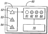
[0028]図2を参照すると、図1のコントローラ12は、ランタイムエンジン42のAEMモジュール60を使用し、ロボットシステム10の様々なジョイントを任意に課題に特化したサブシステムにグループ化する。たとえば、ロボット11が右に向き、物体30を見下し、両ハンド24で物体を把持する場合に、ネックジョイント19および両アーム22のジョイントは、特定の操作のために駆動することができる。これらの課題に特化したサブシステムは、今度は、AEMモジュールを介して較正されたシーケンス構造に結び付けられ、これは、任意の駆動ジョイントの運動を自動的に調整し、複雑な課題なまたは協働作業課題の完了を可能にする。ランタイムエンジン42は、より大きなロボット課題シーケンスの内部にある共存する実行パスのためのソフトウェア機構を提供するために構成することができる。
[0028] Referring to FIG. 2, the
[0029]図2は、独立したサブ課題51の単純化したシリーズの例を提供し、複数の課題実行分岐部52、53、54を備える。分岐部52は実行中であることを示し、この状態は影なしとして図2に示されている。同様に分岐部53、54は影付きで示され、将来において、いくつかのポイントで実行されることを示している。各分岐は、複数の独立したサブ課題を備えることができ、たとえば、複数の独立するサブ課題61、62、63、64を備える分岐部52が示されている。各サブ課題は、協働的に実行することができ、すなわち、同一のロボットの異なるジョイントにより実行され、および/またはロボットシステム10内の複数の異なるロボットのジョイントにより実行される。
FIG. 2 provides an example of a simplified series of
[0030]また、AEMモジュール60は、スケジューリングモジュール70を備えることができ、これは、複数の独立するサブ課題61、62、63、64がそれぞれ独立して完了されることを可能にし、一方、同時に、たとえば図1に示されるデータベースシステム40を介してアクセスされるデータおよびイベントなどのシステムデータおよび共有イベントを通じて課題を同期させる。ランタイムエンジン42による使用のための分岐機構は、コントローラ12のプログラム言語にシームレスに統合され(図1参照)、また、視覚的なプログラムエディタ80を通じてユーザーが設定可能である。
[0030] The
[0031]マルチタスク実行分岐部は、ランタイムエンジン42内のAEMモジュール60により制御することができる。一実施形態におけるスケジューリングモジュール70は、たとえばラウンドロビンスケジューリングスキーム(round-robin scheduling scheme)を用いることで、様々な課題の共有される実行時間を強制することができる。各課題実行分岐部は、自身の状態およびフィードバックを維持し、またそれゆえ、コントローラ12により独立した実行が可能である。さらに、各課題分岐部は、ランタイムエンジン42を使用するコントローラ12により、他の分岐部の実行に干渉することなく一時停止および再開することができる。各分岐部は、データベースシステム40へのアクセス、必要なプログラミングおよび共有されるイベント情報へのアクセスを維持し、また、他の分岐部およびロボットハードウェアからのデータおよびイベントに自由に相互作用できる。
[0031] The multitask execution branch can be controlled by the
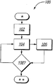
[0032]図3を参照すると、アルゴリズム100は、図1に示されるロボットシステムの様々なジョイントの非同期の制御を提供するために、図1のコントローラ12により実行される。アルゴリズム100はステップ102で開始し、ここで、与えられた協働課題のための必要な制御ノードがコントローラ12内に設定される。たとえば、ノードは、視覚的なプログラミングエディタ80を介してユーザーにより選択することができ、たとえば、視覚的なプログラムエディタ80を介してユーザーがノードを選択することができ、たとえば、割り当てられた課題の達成に用いられる与えられた作業道具のために影響を受けるノードのタッチスクリーン入力により選択できる。説明のための明瞭さのために、比較的単純な作業課題が本明細書では説明され、これは、命令のシーケンスの実行を必要とし、または、物体30を把持するために図1のロボット11の両アーム22を移動させるのに好適なサブプログラムを必要とする。
[0032] Referring to FIG. 3, the
[0033]ノードが設定された後、ステップ104は、サブ課題、たとえば1つのアーム22の移動の実行を開始する。ステップ104により開始されるサブ課題は、自身の課題シーケンスを通じて独立に進行し、アルゴリズム100はステップ106に進む。ステップ106は、図1のロボット11の他のアーム22の移動、または、同一または他のロボットの他の要素の移動のような他のサブ課題の実行を開始する。ステップ104と同様に、ステップ106は、任意の数の課題ステップを備えることができ、これらはステップ106で制御されるアーム22により独立に実行されなければならない。課題実行分岐部は、ステップ104とステップ106との間に存在する。
[0033] After the node is set,
[0034]ステップ108において、コントローラ12は、ランタイムエンジン42を使用し、ステップ104およびステップ106のサブ課題が完了したかどうかを決定する。完了していなければ、ステップ104および/またはステップ106は、ステップ104、106の両方が完了するまで繰り返される。アルゴリズム100は、両方のサブ課題が完了したとき終了する。各サブ課題100は、複数のサブ課題などを備えることができ、簡潔さのために1つのサブ課題が説明される。
[0034] At
[0035]説明の明瞭さのために、1つの課題実行分岐部だけが図3に関して説明される。しかし、図1のランタイムエンジン42は、与えられた協働課題または課題のシーケンスを完了するのに必要な多くの分岐部を割り当て、また調整することができる。すなわち、図1のロボット11、111は、人間のように、複数の同時発生の課題を非同期に実行するように設計される。ランタイムエンジン42は、複数の同時発生的な課題の実行を管理することにより、コントローラ12に関連してまたはその一部として、この制御要求を管理する。ランタイムエンジン42は、任意のポイントにおいて分岐される課題実行のための機構を提供し、たとえば、図3の単純化した実施形態においてステップ104を開始した後に較正された間隔でステップ106を開始し、任意の数のコンピュータ使用のノードに割り当てられる独立の実行パスを形成する。
[0035] For clarity of explanation, only one task execution branch is described with respect to FIG. However, the
[0036]また、図1のランタイムエンジン42は、分離された分岐部が、共有される実行パスに沿って継続する前に、たとえば図3のステップ108において、なめらかに再統合されることを可能にする。同一または異なるロボット11および/または111の制御ノードは、1つ以上のアーム22またはヘッド16のようなサブシステムを形成するためにグループ化されることができ、これは、互いに対して独立に命令、制御することができる。さらに、上述の方法によるランタイムエンジン42の使用は、様々な分岐部の間のリソースの衝突解決のための手段を提供する。換言すれば、ロボット11のヘッドサブシステムは、ロボット111の右アームサブシステムとペアにすることができ、この機能はコントローラ12のプログラム言語において実装され、また、図1の視覚的なプログラムエディタ80または、他の好適なユーザーインターフェースを使用してユーザーが容易にアクセス可能である。
[0036] The run-
[0037]本発明を実行する最良の形態が詳細に説明されたが、本発明の技術分野に精通している当業者は、添付の特許請求の範囲において本発明を実施するための様々な代替設計および実施形態を認識するであろう。 [0037] Although the best mode for carrying out the invention has been described in detail, those skilled in the art are familiar with the various alternatives for practicing the invention within the scope of the appended claims. The design and embodiment will be recognized.
Claims (18)
複数のロボットジョイントを有し、前記ロボットジョイントの各々は、前記協働作業課題の実行中に独立に制御可能であり、
前記ロボットシステムはさらに、前記協働作業課題の実行中に前記ロボットジョイントの運動を制御するコントローラを有し、
前記コントローラは、自動的に、前記ロボットジョイントを課題に特化したサブシステムにグループ化し、課題実行分岐部に到達した際に複数の独立した課題を課題に特化したサブシステムに割り当て、前記課題実行分岐部に到達した後に、課題に特化したサブシステムの、課題に特化したそれぞれのサブシステムによる独立した実行を調整する、ロボットシステム。 A robot system for executing a collaborative work task comprising a plurality of independent tasks, the robot system comprising:
A plurality of robot joints, each of the robot joints being independently controllable during execution of the collaborative work task;
The robot system further includes a controller that controls movement of the robot joint during execution of the collaboration task.
The controller automatically groups the robot joints into task-specific subsystems and assigns a plurality of independent tasks to the task-specific subsystem when the task execution branch is reached. A robot system that, after reaching the execution branch, coordinates the independent execution of the subsystems specialized for the task by each subsystem specialized for the task.
スケジューリングモジュールと、
データベースシステムと、を有し、
前記スケジューリングモジュールは、複数の独立する課題の与えられた1つを他の複数の独立する課題から独立して完成させ、前記データベースシステムからのシステムデータおよび共有されるイベント情報を用いて、前記複数の独立する課題の実行を同期させる、ロボットシステム。 The robot system according to claim 7, further comprising:
A scheduling module;
A database system,
The scheduling module completes a given one of a plurality of independent tasks independently of a plurality of other independent tasks, and uses the system data from the database system and shared event information to Robot system that synchronizes the execution of independent tasks.
前記ロボットジョイントを自動的に課題に特化したサブシステムにグループ化するステップと、
課題実行分岐部に到達した際に、複数の独立するサブ課題を課題に特化したサブシステムに割り当てるステップと、
課題実行分岐部に到達した後に、それぞれの課題に特化したサブシステムによる複数の独立するサブ課題の独立した実行を調整するステップと、を有する方法。 A method for performing a collaborative work task comprising a plurality of independent sub-tasks using a robot system comprising a plurality of independently controllable robot joints, the method comprising:
Automatically grouping the robot joints into sub-systems specific to the task;
Assigning a plurality of independent sub-tasks to a task-specific subsystem when the task execution branch is reached;
Adjusting the independent execution of a plurality of independent sub-tasks by a subsystem specialized for each task after reaching the task execution branch.
ランタイムエンジンを使用して、課題実行分岐部において、前記協働作業課題の前記複数の独立するサブ課題を自動的に分岐させるステップ、を有する、方法。 The method of claim 12, further comprising:
Automatically branching the plurality of independent sub-tasks of the collaborative work task at a task execution branch using a run-time engine.
前記視覚的プログラムエディタを用いて前記ランタイムエンジン内の分岐シーケンスを設定するステップを有する、方法。 The method of claim 15, wherein the robotic system includes a visual program editor, the method further comprising:
Setting a branch sequence in the runtime engine using the visual program editor.
ラウンドロビンスケジューリングスキームを使用するスケジューリングモジュールを介して、複数の独立するサブ課題の共有される実行時間を強制するステップを有する、方法。 The method of claim 17, further comprising:
Forcing a shared execution time of a plurality of independent sub-tasks via a scheduling module using a round robin scheduling scheme.
Applications Claiming Priority (2)
| Application Number | Priority Date | Filing Date | Title |
|---|---|---|---|
| US12/887,972 | 2010-09-22 | ||
| US12/887,972 US8731714B2 (en) | 2010-09-22 | 2010-09-22 | Concurrent path planning with one or more humanoid robots |
Publications (2)
| Publication Number | Publication Date |
|---|---|
| JP2012066376A true JP2012066376A (en) | 2012-04-05 |
| JP2012066376A5 JP2012066376A5 (en) | 2013-05-02 |
Family
ID=45818456
Family Applications (1)
| Application Number | Title | Priority Date | Filing Date |
|---|---|---|---|
| JP2011140520A Pending JP2012066376A (en) | 2010-09-22 | 2011-06-24 | Concurrent path planning with one or more humanoid robots |
Country Status (3)
| Country | Link |
|---|---|
| US (1) | US8731714B2 (en) |
| JP (1) | JP2012066376A (en) |
| DE (1) | DE102011113590B4 (en) |
Families Citing this family (19)
| Publication number | Priority date | Publication date | Assignee | Title |
|---|---|---|---|---|
| TW201228785A (en) * | 2011-01-14 | 2012-07-16 | Hon Hai Prec Ind Co Ltd | Manipulator positioning device and manipulator with same |
| US10054933B2 (en) * | 2012-03-27 | 2018-08-21 | Sirqul, Inc. | Controlling distributed device operations |
| WO2014002678A1 (en) * | 2012-06-29 | 2014-01-03 | 三菱電機株式会社 | Robot control device and robot control method |
| US9465384B1 (en) * | 2013-06-24 | 2016-10-11 | Redwood Robotics, Inc. | Methods and systems for tiered programming of robotic device |
| US9409292B2 (en) | 2013-09-13 | 2016-08-09 | Sarcos Lc | Serpentine robotic crawler for performing dexterous operations |
| JP2015136762A (en) * | 2014-01-23 | 2015-07-30 | セイコーエプソン株式会社 | Processor, robot, robot system and processing method |
| US9566711B2 (en) * | 2014-03-04 | 2017-02-14 | Sarcos Lc | Coordinated robotic control |
| US9701018B2 (en) | 2014-04-01 | 2017-07-11 | Bot & Dolly, Llc | Software interface for authoring robotic manufacturing process |
| US9841749B2 (en) | 2014-04-01 | 2017-12-12 | Bot & Dolly, Llc | Runtime controller for robotic manufacturing system |
| DE202014003133U1 (en) * | 2014-04-11 | 2015-07-15 | Kuka Systems Gmbh | Robotic workstation |
| US9555545B2 (en) | 2014-05-21 | 2017-01-31 | Bot & Dolly, Llc | Systems and methods for time-based parallel robotic operation |
| US9278449B1 (en) | 2014-05-21 | 2016-03-08 | Bot & Dolly, Llc | Closed-loop control system for robotic operation |
| US9308647B2 (en) | 2014-06-03 | 2016-04-12 | Bot & Dolly, Llc | Systems and methods for instructing robotic operation |
| CN104440910B (en) * | 2014-11-07 | 2016-05-04 | 绵阳市维博电子有限责任公司 | A kind of method and system that realize robot both hands arm Synchronization Control |
| US11312018B2 (en) * | 2014-11-14 | 2022-04-26 | Transportation Ip Holdings, Llc | Control system with task manager |
| US9555846B1 (en) | 2015-03-20 | 2017-01-31 | Google Inc. | Pelvis structure for humanoid robot |
| US9707680B1 (en) * | 2015-05-28 | 2017-07-18 | X Development Llc | Suggesting, selecting, and applying task-level movement parameters to implementation of robot motion primitives |
| US10071303B2 (en) | 2015-08-26 | 2018-09-11 | Malibu Innovations, LLC | Mobilized cooler device with fork hanger assembly |
| US10807659B2 (en) | 2016-05-27 | 2020-10-20 | Joseph L. Pikulski | Motorized platforms |
Citations (12)
| Publication number | Priority date | Publication date | Assignee | Title |
|---|---|---|---|---|
| JP2000267707A (en) * | 1999-03-15 | 2000-09-29 | Omron Corp | Sequence controller, maintenance method for maintenance area in the same device, and recording medium for storing computer program for executing the same method |
| JP2002120174A (en) * | 2000-10-11 | 2002-04-23 | Sony Corp | Authoring system, authoring method and storage medium |
| JP2003291083A (en) * | 2002-03-28 | 2003-10-14 | Toshiba Corp | Robot device, robot controlling method, and robot delivery system |
| JP2004114285A (en) * | 2002-09-02 | 2004-04-15 | Sony Corp | Robotic device and its behavior control method |
| JP2004181613A (en) * | 2002-03-18 | 2004-07-02 | Sony Corp | Robot device, device and method for controlling operation of legged locomotion robot, sensor system for legged locomotion robot, and moving body device |
| JP2004195554A (en) * | 2002-12-16 | 2004-07-15 | Sony Corp | Leg type mobile robot |
| JP2004283960A (en) * | 2003-03-20 | 2004-10-14 | Sony Corp | Robot device, method of controlling behavior and program thereof |
| JP2005125460A (en) * | 2003-10-24 | 2005-05-19 | Sony Corp | Motion editing device, motion editing method, and computer program for robotic device |
| JP2005144624A (en) * | 2003-11-18 | 2005-06-09 | Sony Corp | Legged mobile robot |
| JP2005313303A (en) * | 2004-04-30 | 2005-11-10 | Japan Science & Technology Agency | Robot remote control system |
| JP2008515316A (en) * | 2004-09-29 | 2008-05-08 | コーニンクレッカ フィリップス エレクトロニクス エヌ ヴィ | Network array, transfer device, and operation method of transfer device |
| JP2008307662A (en) * | 2007-06-15 | 2008-12-25 | Fujitsu Ltd | Robot system, editor terminal and editor program |
Family Cites Families (19)
| Publication number | Priority date | Publication date | Assignee | Title |
|---|---|---|---|---|
| US4954948A (en) * | 1986-12-29 | 1990-09-04 | Motorola, Inc. | Microprocessor operating system for sequentially executing subtasks |
| EP1090722B1 (en) * | 1999-09-16 | 2007-07-25 | Fanuc Ltd | Control system for synchronously cooperative operation of a plurality of robots |
| DE10032096A1 (en) * | 2000-07-01 | 2002-01-24 | Kuka Roboter Gmbh | Device network and control cabinet for such |
| JP3504222B2 (en) * | 2000-09-04 | 2004-03-08 | ファナック株式会社 | Robot controller |
| CN1649698A (en) | 2002-03-18 | 2005-08-03 | 索尼株式会社 | Robot device, legged locomotion robot operation control device and operation control method, legged locomotion robot sensor system, and locomotion device |
| US7103447B2 (en) * | 2002-09-02 | 2006-09-05 | Sony Corporation | Robot apparatus, and behavior controlling method for robot apparatus |
| US7072740B2 (en) | 2002-12-16 | 2006-07-04 | Sony Corporation | Legged mobile robot |
| DE10314025B4 (en) * | 2003-03-28 | 2010-04-01 | Kuka Roboter Gmbh | Method and device for controlling a plurality of handling devices |
| US6804580B1 (en) * | 2003-04-03 | 2004-10-12 | Kuka Roboter Gmbh | Method and control system for controlling a plurality of robots |
| SE0303384D0 (en) * | 2003-12-15 | 2003-12-15 | Abb Ab | Control system, method and computer program |
| US20050132121A1 (en) * | 2003-12-16 | 2005-06-16 | Wind River Systems, Inc. | Partitioned operating system tool |
| JP2005190437A (en) * | 2003-12-26 | 2005-07-14 | Fanuc Ltd | Control device management system |
| SE0402098D0 (en) * | 2004-08-30 | 2004-08-30 | Abb Ab | A control system |
| US7383100B2 (en) * | 2005-09-29 | 2008-06-03 | Honda Motor Co., Ltd. | Extensible task engine framework for humanoid robots |
| KR20070075957A (en) * | 2006-01-17 | 2007-07-24 | 주식회사 로보스타 | Robot control system for multi tasking based task |
| EP2014425B1 (en) * | 2007-07-13 | 2013-02-20 | Honda Research Institute Europe GmbH | Method and device for controlling a robot |
| KR101021836B1 (en) * | 2008-10-09 | 2011-03-17 | 한국전자통신연구원 | System for cooperation of multiple mobile robot using dynamic behavior binding and method thereof |
| US8364314B2 (en) * | 2009-04-30 | 2013-01-29 | GM Global Technology Operations LLC | Method and apparatus for automatic control of a humanoid robot |
| US9046892B2 (en) * | 2009-06-05 | 2015-06-02 | The Boeing Company | Supervision and control of heterogeneous autonomous operations |
-
2010
- 2010-09-22 US US12/887,972 patent/US8731714B2/en active Active
-
2011
- 2011-06-24 JP JP2011140520A patent/JP2012066376A/en active Pending
- 2011-09-16 DE DE102011113590.5A patent/DE102011113590B4/en not_active Expired - Fee Related
Patent Citations (12)
| Publication number | Priority date | Publication date | Assignee | Title |
|---|---|---|---|---|
| JP2000267707A (en) * | 1999-03-15 | 2000-09-29 | Omron Corp | Sequence controller, maintenance method for maintenance area in the same device, and recording medium for storing computer program for executing the same method |
| JP2002120174A (en) * | 2000-10-11 | 2002-04-23 | Sony Corp | Authoring system, authoring method and storage medium |
| JP2004181613A (en) * | 2002-03-18 | 2004-07-02 | Sony Corp | Robot device, device and method for controlling operation of legged locomotion robot, sensor system for legged locomotion robot, and moving body device |
| JP2003291083A (en) * | 2002-03-28 | 2003-10-14 | Toshiba Corp | Robot device, robot controlling method, and robot delivery system |
| JP2004114285A (en) * | 2002-09-02 | 2004-04-15 | Sony Corp | Robotic device and its behavior control method |
| JP2004195554A (en) * | 2002-12-16 | 2004-07-15 | Sony Corp | Leg type mobile robot |
| JP2004283960A (en) * | 2003-03-20 | 2004-10-14 | Sony Corp | Robot device, method of controlling behavior and program thereof |
| JP2005125460A (en) * | 2003-10-24 | 2005-05-19 | Sony Corp | Motion editing device, motion editing method, and computer program for robotic device |
| JP2005144624A (en) * | 2003-11-18 | 2005-06-09 | Sony Corp | Legged mobile robot |
| JP2005313303A (en) * | 2004-04-30 | 2005-11-10 | Japan Science & Technology Agency | Robot remote control system |
| JP2008515316A (en) * | 2004-09-29 | 2008-05-08 | コーニンクレッカ フィリップス エレクトロニクス エヌ ヴィ | Network array, transfer device, and operation method of transfer device |
| JP2008307662A (en) * | 2007-06-15 | 2008-12-25 | Fujitsu Ltd | Robot system, editor terminal and editor program |
Also Published As
| Publication number | Publication date |
|---|---|
| US8731714B2 (en) | 2014-05-20 |
| DE102011113590A1 (en) | 2012-08-30 |
| US20120072019A1 (en) | 2012-03-22 |
| DE102011113590B4 (en) | 2015-06-25 |
Similar Documents
| Publication | Publication Date | Title |
|---|---|---|
| US8731714B2 (en) | Concurrent path planning with one or more humanoid robots | |
| JP2012066376A5 (en) | ||
| JP5180989B2 (en) | Method and apparatus for automatic control of a humanoid robot | |
| US8868241B2 (en) | Robot task commander with extensible programming environment | |
| US8260460B2 (en) | Interactive robot control system and method of use | |
| US9120224B2 (en) | Framework and method for controlling a robotic system using a distributed computer network | |
| Vick et al. | Robot control as a service—towards cloud-based motion planning and control for industrial robots | |
| JP6010776B2 (en) | Robot system control method and robot system | |
| US20130096719A1 (en) | Method for dynamic optimization of a robot control interface | |
| Braumann et al. | Adaptive Robot Control | |
| JP2012096349A (en) | Robust operation of tendon-driven robot finger using force and position-based control law | |
| Matthaiakis et al. | Flexible programming tool enabling synergy between human and robot | |
| Mineo et al. | Interfacing toolbox for robotic arms with real-time adaptive behavior capabilities | |
| Di Napoli et al. | A novel control strategy for youBot arm | |
| Glück et al. | Towards a tool-based methodology for developing software for dynamic robot teams | |
| Zhang et al. | A real-time robot control framework using ROS Control for 7-DoF light-weight robot | |
| Nevliudov et al. | Multithreaded Software Control of Industrial Manipulator Movement | |
| Aldridge et al. | Control architecture for the robonaut space humanoid | |
| JP7060700B2 (en) | Coordination system, handling equipment and method | |
| JP2023505631A (en) | A composability framework for robotic control systems | |
| Vistein et al. | Instantaneous switching between real-time commands for continuous execution of complex robotic tasks | |
| Pardo-Castellote et al. | Experimental integration of planning in a distributed control system | |
| RU2813444C1 (en) | Mixed reality human-robot interaction system | |
| Al Saidi et al. | Kinematic properties and control for reconfigurable robotic system | |
| Zhong et al. | Design of a Framework for Implementation of Industrial Robot Manipulation Using PLC and ROS 2 |
Legal Events
| Date | Code | Title | Description |
|---|---|---|---|
| A977 | Report on retrieval |
Free format text: JAPANESE INTERMEDIATE CODE: A971007 Effective date: 20121017 |
|
| A131 | Notification of reasons for refusal |
Free format text: JAPANESE INTERMEDIATE CODE: A131 Effective date: 20121227 |
|
| A524 | Written submission of copy of amendment under article 19 pct |
Free format text: JAPANESE INTERMEDIATE CODE: A524 Effective date: 20130319 |
|
| A131 | Notification of reasons for refusal |
Free format text: JAPANESE INTERMEDIATE CODE: A131 Effective date: 20131002 |
|
| A601 | Written request for extension of time |
Free format text: JAPANESE INTERMEDIATE CODE: A601 Effective date: 20131220 |
|
| A602 | Written permission of extension of time |
Free format text: JAPANESE INTERMEDIATE CODE: A602 Effective date: 20131226 |
|
| A521 | Request for written amendment filed |
Free format text: JAPANESE INTERMEDIATE CODE: A523 Effective date: 20140401 |
|
| A02 | Decision of refusal |
Free format text: JAPANESE INTERMEDIATE CODE: A02 Effective date: 20140711 |