JP2010524295A - First portable communication device - Google Patents
First portable communication device Download PDFInfo
- Publication number
- JP2010524295A JP2010524295A JP2010500924A JP2010500924A JP2010524295A JP 2010524295 A JP2010524295 A JP 2010524295A JP 2010500924 A JP2010500924 A JP 2010500924A JP 2010500924 A JP2010500924 A JP 2010500924A JP 2010524295 A JP2010524295 A JP 2010524295A
- Authority
- JP
- Japan
- Prior art keywords
- communication device
- portable communication
- image
- scene
- user
- Prior art date
- Legal status (The legal status is an assumption and is not a legal conclusion. Google has not performed a legal analysis and makes no representation as to the accuracy of the status listed.)
- Withdrawn
Links
Images


Classifications
-
- H—ELECTRICITY
- H04—ELECTRIC COMMUNICATION TECHNIQUE
- H04N—PICTORIAL COMMUNICATION, e.g. TELEVISION
- H04N7/00—Television systems
- H04N7/14—Systems for two-way working
- H04N7/141—Systems for two-way working between two video terminals, e.g. videophone
- H04N7/142—Constructional details of the terminal equipment, e.g. arrangements of the camera and the display
- H04N2007/145—Handheld terminals
Abstract
本発明によれば、第2の携帯可能な通信装置と通信するための第1の携帯可能な通信装置であって、ビデオおよびオーディオ情報を送信および受信するための通信モジュールと、電子ディスプレイと、第1のシーンの画像を捕捉するための第1の画像捕捉装置と、第1のシーンとは異なる第2のシーンの画像を捕捉するための第2の画像捕捉装置と、第1もしくは第2のシーンの画像のいずれか又はこれらの組み合わせを第2の携帯可能な通信装置に送信するためのユーザーコマンドに応答する手段を含む第1の携帯可能な通信装置が提供される。 According to the present invention, a first portable communication device for communicating with a second portable communication device, a communication module for transmitting and receiving video and audio information, an electronic display, A first image capturing device for capturing an image of the first scene, a second image capturing device for capturing an image of a second scene different from the first scene, and the first or second A first portable communication device is provided that includes means for responding to a user command for transmitting any of the scene images or a combination thereof to the second portable communication device.
Description
本発明は、双方向ビデオ通信システムに関し、より詳細には、携帯電話に関する。 The present invention relates to a two-way video communication system, and more particularly to a mobile phone.
2つの異なるサイト間でビデオ画像と音声の通信を可能にする通信チャネルにより接続された2つの位置の各々においてディスプレイとカメラを具備する双方向ビデオシステムが利用可能である。もともとは、かかるシステムは、音声を捕捉するためのマイクロフォンおよび音声を発するスピーカーとともに、遠隔シーンを表示するためのビデオモニタと、ローカルシーンを捕捉するためにビデオモニタの縁部に又は縁部付近に位置する別個のビデオカメラの各サイトにおける設定に頼る。 An interactive video system with a display and camera is available at each of two locations connected by a communication channel that enables video image and audio communication between two different sites. Originally, such a system, with a microphone for capturing audio and a speaker emitting sound, with a video monitor for displaying a remote scene and at or near the edge of the video monitor to capture a local scene. Rely on the settings at each site of a separate video camera located.
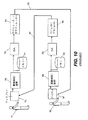
図10には、典型的な従来技術の双方向通信システムが示されており、ここで、第1の視聴者71は第1のディスプレイ73を見ている。第1の画像捕捉装置75は、第1の観察者71の画像を捕捉する。画像がスチルデジタル画像である場合には、そのスチルデジタル画像は、呼び出しのために第1のスチル画像メモリー77に記憶される。第1のスチル画像メモリー77から呼び出されたスチル画像、または第1の画像捕捉装置75から直接捕捉されたビデオ画像は、第1のD/Aコンバーター79を使用してデジタル信号からアナログ信号に変換される。第1のモジュレーター/デモジュレーター81は、次に、第1の通信経路83を使用してアナログ信号を第2のディスプレイ87に送り、第2のディスプレイ87において第2の視聴者85は捕捉画像を見ることができる。
In FIG. 10, a typical prior art two-way communication system is shown, where a
同様に、第2の画像捕捉装置89は、第2の観察者85の画像を捕捉する。捕捉された画像データは第2のD/Aコンバーター93に送られ、そこでアナログ信号に変換されるが、呼び出しのために第2のスチル画像メモリー91にまず記憶される。捕捉された画像のアナログ信号は第2のモジュレーター/デモジュレーター95に送られ、そして、第2の通信チャネル97を通じて、第1の観察者71による観察のために第1のディスプレイ73に送られる。
Similarly, the second
かかるシステムは、テレビ会議および他の双方向通信用途のために製造され使用されてきたが、それらの有効性および幅広い支持を限定してきた幾つかの重大な実際上の欠点がある。かかるシステムの有用性および質を発展させることはかなり最近の研究で注目されたが、提案された解決法の多くは、現実の相互作用に非常に似ているため、双方向バーチャルリアリティの形態を生じる。これらの改良点の多くは通信帯域幅、ユーザーインターフェース制御、およびかかるシステムの画像捕捉コンポーネントおよびディスプレイコンポーネントの能力に着目したものである。他の改良点は、捕捉装置およびディスプレイを統合して、バーチャルリアリティ環境を改善しようとするものである。かかるシステムの1つの重大な欠点は、それらの費用と、携帯性に欠くことにある。さらに、制御されない環境において、音声ノイズは鮮明性をかなり低下させ、ユーザーがビデオ画像を制御することが困難であることがある。 While such systems have been manufactured and used for video conferencing and other two-way communication applications, there are several significant practical drawbacks that have limited their effectiveness and broad support. While developing the usefulness and quality of such systems has been noted in fairly recent studies, many of the proposed solutions are very similar to real interactions, so the form of interactive virtual reality is Arise. Many of these improvements focus on communication bandwidth, user interface control, and the capabilities of the image capture and display components of such systems. Another improvement is to integrate the capture device and display to improve the virtual reality environment. One significant drawback of such systems is their lack of cost and portability. Furthermore, in an uncontrolled environment, audio noise can significantly reduce clarity and make it difficult for the user to control the video image.
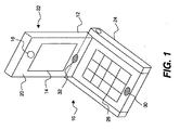
図1を参照すると、現存する携帯電話100は、典型的には、通信モジュール(図示せず)、ユーザー相互作用のためのキーパッド26、統合レンズを通じて画像を撮影するための画像生成装置16、およびユーザーに指示およびステータスを表示するためのディスプレイスクリーン14を具備する。かかる装置100は、オーディオ通信に有用であり、当該電話により撮影されたデジタル画像を伝送することができ、インターネットコンテントをダウンロードし表示することができるけれども、ビデオ通信には一般的には使用されない。センサーおよびディスプレイを具備する様々なデザインが当該技術分野で知られている。例えば、Tsuboiによる「Display apparatus with camera and communication apparatus(カメラ付きディスプレイ装置および通信装置)」という題名の米国特許出願第2005/0128332号明細書には、ディスプレイを見る人のほぼ顔全体の画像を得るための画素の内蔵アレイを有する携帯型ディスプレイが記載されている。Uyによる「Integrated sensing display(一体型検出ディスプレイ)」という題名の米国特許出願第2006/0007222号明細書には、ディスプレイ表面に沿って分配された画像検出素子と組み合わされたディスプレイ要素を具備するディスプレイが開示されている。双方向ディスプレイおよび画像捕捉通信にとって好適な光学機器を提供しようとする多くの他の試みは、ピンホールカメラコンポーネントを使用するものであった。例えば、「Integral eye-path alignment on telephony and computer video devices using a pinhole image sensing device(ピンホール画像検出装置を使用する電話通信およびコンピュータービデオ装置でのインテグラルアイパスアラインメント)」という題名のRamboらへの米国特許第6,888,562号明細書には、双方向ビジュアル通信装置およびかかる装置の操作方法が記載されている。
Referring to FIG. 1, an existing
多くの従来の解決法に共通する1つの問題は、観察場所における観察者の移動および変化を補償できないことに関連する。これは、様々な位置に回転可能なカバーを有するカメラを設けることにより部分的に解決できる。ここで、回転可能なカバーの幾つかはディスプレイコンポーネントに対する支持体を提供することができる。例えば、「Image Display having a Cover Member(カバー部材を有する画像ディスプレイ)」という題名の米国特許出願公開第2003/0227676号に、かかるカバーが示されている。この問題に対する他の対処法は、Hillisらによる「Method and apparatus maintaining eye contact in video delivery systems using view morphing(ビューモーフィングを使用するビデオデリバリーシステムにおける視線を維持する方法および装置)」という題名の米国特許出願公開第2004/0196360号に記載されているもののような、複雑なシミュレート画像を生成させるための比較的複雑なシステムであった。この問題に対する別の対処法は、「Video-teleconferencing system with eye-gaze correction(視線補正を用いるビデオ遠隔会議システム)」という題名のZhangらへの米国特許第6,771,303号明細書に提案されており、この方法は、各電話会議参加者について頭部の軌道と複数のカメラを使用して画像合成を行う。しかしながら、かかる方法は、合成画像コンテントを正確なリアルタイムイメージングに置き換えることを試みることによって一体型ディスプレイおよび画像捕捉装置についてのイメージング問題を回避するものであるため、より有効なビデオ遠隔会議および通信に必要とされる現実の相互作用を提供することの必要性に答えるものではない。 One problem common to many conventional solutions is related to the inability to compensate for observer movement and changes at the viewing location. This can be partially solved by providing a camera with a rotatable cover at various positions. Here, some of the rotatable covers can provide a support for the display component. Such a cover is shown, for example, in US 2003/0227676 entitled “Image Display having a Cover Member”. Another approach to this problem is a US patent entitled “Method and apparatus maintaining eye contact in video delivery systems using view morphing” by Hillis et al., Entitled “Method and apparatus maintaining eye contact in video delivery systems using view morphing”. It was a relatively complex system for generating complex simulated images, such as those described in published application No. 2004/0196360. Another approach to this problem is proposed in US Pat. No. 6,771,303 to Zhang et al. Entitled “Video-teleconferencing system with eye-gaze correction”. In this method, image synthesis is performed using a head trajectory and a plurality of cameras for each conference call participant. However, this method is necessary for more effective video teleconferencing and communication as it avoids imaging problems for integrated displays and image capture devices by attempting to replace the composite image content with accurate real-time imaging. It does not answer the need to provide real-life interactions.
携帯電話による画像通信で遭遇する別の問題は、従来型の配置に関連する問題、すなわちユーザーが自分または手に持っている被写体の写真を撮影することが困難であることである。カメラの揺れは、シーンの画質を低下させることがある。ユーザーの画像が求められる場合には、ユーザーがディスプレイ上の撮影画像を見ることとユーザー自身を撮影することの両方をユーザーが行うことができるようにはセンサーは通常方向付けられないという点で、この問題はますます顕著になる。焦点距離および相対的向きに関する問題も厄介である。 Another problem encountered in image communication with mobile phones is the problem associated with conventional placement, i.e., it is difficult to take a picture of a subject that the user has on his or her hand. Camera shake can degrade the image quality of the scene. If the user ’s image is required, the sensor is usually not oriented so that the user can both view the captured image on the display and shoot the user himself, This problem becomes more pronounced. Problems with focal length and relative orientation are also cumbersome.
従って、提案された解決法は、実際的な携帯電話の必要性を十分に満足しない。遠隔会議および他の双方向ビデオ通信の改善のために提案された解決法の急増は、この問題がどれほど複雑であるかを表しており、重大な問題が残っていることを示している。 Thus, the proposed solution does not fully satisfy the practical mobile phone needs. The proliferation of solutions proposed for improving teleconferencing and other two-way video communications represents how complex this problem is, indicating that significant problems remain.
本発明によれば、第2の携帯可能な通信装置と通信するための第1の携帯可能な通信装置であって、ビデオおよびオーディオ情報を送信および受信するための通信モジュールと、電子ディスプレイと、第1のシーンの画像を捕捉するための第1の画像捕捉装置と、第1のシーンとは異なる第2のシーンの画像を捕捉するための第2の画像捕捉装置と、第1もしくは第2のシーンの画像又はこれらの組み合わせを第2の携帯可能な通信装置に送信するためのユーザーコマンドに応答する手段を含む第1の携帯可能な通信装置が提供される。 According to the present invention, a first portable communication device for communicating with a second portable communication device, a communication module for transmitting and receiving video and audio information, an electronic display, A first image capturing device for capturing an image of the first scene, a second image capturing device for capturing an image of a second scene different from the first scene, and the first or second A first portable communication device is provided that includes means for responding to a user command to send an image of the scene or a combination thereof to the second portable communication device.
本発明は、ユーザーおよびシーンの両方を容易に撮像することができ、周囲ノイズを低減してオーディオ通信をはっきりさせることができ、使い勝手の良い、安定した、ハンズフリー画像取得、正確な画像捕捉および手に持った被写体の画像捕捉のための方法を提供することのできる第1の携帯可能な双方向通信装置を提供する。 The present invention can easily capture both the user and the scene, can reduce ambient noise and clarify audio communication, is easy to use, stable, hands-free image acquisition, accurate image capture and Provided is a first portable two-way communication device that can provide a method for capturing an image of an object held in a hand.
本発明の実施態様に従う図1、2および12を参照すると、第1の携帯可能な通信装置10,10Aは、スチル、ビデオおよびオーディオ情報を送信および受信するための通信モジュール12と、第1の携帯可能な通信装置10の第1の側20の上にスチルまたはビデオ画像を表示するための電子ディスプレイ14と、第1のシーンの第1の携帯可能な通信装置10の第1の側からスチルまたはビデオ画像を捕捉するための第1の画像捕捉装置16と、第1のシーンとは異なる第2のシーンの第1の携帯可能な通信装置10の第2の側22からスチルまたはビデオ画像を捕捉するための第2の画像捕捉装置18とを含み、第1もしくは第2のシーンのいずれかの画像またはそれらの組み合わせを第2の携帯可能な通信装置10Bに送信するためのユーザーコマンドに対して応答する。かかるユーザーコマンドは、様々な方法、例えばキーパッド26を介して、オーディオインターフェース、例えばマイクロフォン30を介して、またはタッチスクリーンを備えたディスプレイ14を介して提供できる。図12に示されているように、ユーザーコマンドに対して応答する構造としては、CPU53およびオーディオ/ビデオプロセッサー54が挙げられる。第1の画像捕捉装置16および第2の画像捕捉装置18は、同時にまたは個別に使用できる。
Referring to FIGS. 1, 2 and 12 according to an embodiment of the present invention, a first
ユーザーコマンドは、電子ディスプレイ14上に第1のシーンの画像を表示するため、および、複合画像(combined image)を送信するのに先立って第2のシーンと組み合わせるべきかかる画像の部分を選択するための構造をさらに含むことができる。例えば、第1の画像捕捉装置により捕捉されたままのユーザーの顔の画像を抽出し、第2の画像捕捉装置により捕捉されたシーン画像と組み合わせて複合画像を形成することができる。代わりに、第1または第2のシーンのいずれかの画像を表示するためのユーザーコマンドに対して応答するディスプレイを設けることができる。
The user command is for displaying an image of the first scene on the
マイクロフォン30は、画像が送信される際にオーディオ情報を送信するためのオーディオ情報を捕捉する。オーディオ情報を送信するために少なくとも1つのスピーカー32が設けられる。マイクロフォン30は、ここでは、第1のシーンに隣接して位置し、第1のシーンで生成したオーディオ信号を捕捉するために第1の側に位置する。第1の携帯可能な通信装置は、さらに、第2の携帯可能な通信装置からのビデオ画像を受信して表示することができ、第2の携帯可能な通信装置から受信したオーディオを受信して再生することができる。
The
メカニカルスタンド24は、第1の携帯可能な通信装置10を表面に置くことができてユーザーが当該装置を手に持つ必要なしにビデオ通信が可能であるように、第1の携帯可能な通信装置10に組み合わされている。かかる配置では、例えば、電子ディスプレイ14はユーザーに見え、第1の画像捕捉装置16はユーザーの画像(第1のシーン)を捕捉し、第2の画像捕捉装置18はユーザーにより観察された第2のシーンの少なくとも一部の画像を捕捉する。
The
メカニカルスタンド24は第1の携帯可能な通信装置10のプロファイルを減少させるために折り返し位置に折り返すことができ(図1に示されているように)、または、表面上で第1の携帯可能な通信装置10を支持するために拡張位置に広げることができる(図2に示されているように)。図1に示されているように、スタンドはキーパッド26の側部に重なっている。本発明の別の実施態様において、メカニカルスタンド24はキーパッド26の下方(図3に示されているように)またはディスプレイ14(図示せず)の後方に設けることができる。
The
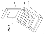
図4に示されているように、本発明のさらに別の実施態様において、使用勝手の良い通信が可能となるような好ましい配置で第1の携帯可能な装置10をメカニカルスタンド24に挿入して載置することができるように、メカニカルスタンド24は第1の携帯可能な通信装置10の本体とは物理的に分離した構造体であることができる。
As shown in FIG. 4, in yet another embodiment of the present invention, the first
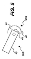
本発明の別の実施態様において、第1の携帯可能な通信装置は、第1および第2の折り返し部90Aおよび90Bを含んで成る折り返し装置であることができ、ハンズフリー機構24が、第1の携帯可能な通信装置10の折り返し部90Aおよび90Bを互いに対して2またはそれ以上の望ましい角度で保持することができる。折り返し部のうちの1つ(例えば、90B)は、表面上に第1の携帯可能な通信装置を支持するために使用できる。図5を参照すると、かかる実施態様において、ハンズフリー機構24は、第1および第2の折り返し部90Aおよび90Bをそれぞれ望ましい角度に保持するために、第1の折り返し部90Aに組み込まれた第1の要素42内の2またはそれ以上の戻り止め40と、第2の折り返し部90Bに組み込まれた第2の要素46内の突起部を用いる。
In another embodiment of the present invention, the first portable communication device can be a folding device comprising first and
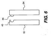
図6を参照すると、本発明のさらに別の実施態様において、メカニカルスタンド24は、例えば、メカニカルスタンド24に突起部44を用い、第1の携帯可能な通信装置10に戻り止め40を用いることによって、第1の携帯可能な通信装置から取り外し可能である。一形態において、戻り止め40および突起部44は整合しており、加えられた機械的圧力、例えばメカニカルスタンド24により加えられた機械的圧力によって所定の位置に保持される。別の形態において、メカニカルスタンド24は、一時的にわずかに変形して戻り止め40および第1の携帯可能な通信装置10からスタンド24および突起部44を解放する。かかる機械的構造およびこれを実現するのに有用な材料(例えばプラスチック)は当該技術分野でよく知られている。
Referring to FIG. 6, in yet another embodiment of the present invention, the
2つの画像センサーおよびメカニカルスタンドを有する第1の携帯可能な通信装置10を提供することによって、当該第1の携帯可能な通信装置は、手持ち式であるというよりもむしろ表面上に置くことができるものである。第1の画像センサーを使用することによって、ユーザー、ユーザーの身振り、またはユーザーが手に持っている被写体を、カメラの揺れなしに容易に撮像できるという画像取得を提供することができる。加えて、ユーザーが見たシーンを撮像することもでき、それによって、ユーザーの判断で、ユーザーまたはそのユーザーの周囲の両方の質の高い通信が可能となる。さらに、ユーザーは、自分自身または別のシーンの画像捕捉が進行している間に、ディスプレイ上で通信画像を見ることができる。
By providing a first
図7を参照すると、本発明の別の実施態様において、第1および第2の画像捕捉装置16および18はそれぞれ、別個の画像センサー50,52とレンズ51,51Aを各々有する別個のデジタルカメラであることができる。図8に示されている別の実施態様において、第1および第2の画像捕捉装置16および18は、レンズ51および51Bのそれぞれからの光線を結合するための撮像光学素子(例えば、ビームスプリッター62、ミラー60およびシャッター64を含む)とともに、共通画像センサー50および別個のレンズ51および51Bを有することができる。かかる画像結合光学素子は当該技術分野で画像センサーおよびレンズとして良く知られている。
Referring to FIG. 7, in another embodiment of the present invention, the first and second
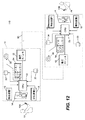
図7を参照すると、本発明のさらに別の実施態様において、第1の携帯可能な通信装置10は、第2のマイクロフォン33をさらに含み、この第2のマイクロフォン33は、第2のシーンに隣接して位置する第2の側に位置し、第2のシーンからのオーディオ信号を記録し、マイクロフォン30の信号から第2のマイクロフォン33の信号を差し引くことで、記録されたオーディオ信号中の周囲ノイズを低減する。代わりに、信号を、第1または第2のマイクロフォンから単独で送信することができ、あるいは、オーディオ信号を組み合わせることができ、例えばコンサートの設定において有用であろう。マイクロフォン30は、携帯可能な通信装置12の第1の側20に位置することができる。本発明のさらなる実施態様において、第1の携帯可能な通信装置10は、さらに、第1の画像捕捉装置16により捕捉されたユーザーの画像を抽出し、その抽出した画像を第2の画像捕捉装置18により捕捉されたシーン画像と組み合わせて複合画像を形成することができる。好適なコンピューターまたは画像プロセッサーおよびオーディオ/ビデオプロセッサー54は当該技術分野で知られている。図13を参照すると、処理された画像およびオーディオ信号を、先行技術の携帯電話に普通に見られるように、増幅器58により増幅し、トランシーバー通信モジュール回路56により送ることができる。この回路は、例えばキーパッドまたはオーディオ信号を介しての、一方の画像捕捉装置16または他方の画像捕捉装置18により捕捉された画像を表示せよとのユーザーからのコマンドに応答することもできる。
Referring to FIG. 7, in yet another embodiment of the present invention, the first
図9を参照すると、本発明の第1の携帯可能な通信装置10は、第1および第2の携帯可能な通信装置10Aおよび10Bを含んで成る携帯可能な通信システムにおいて使用できる。第1および第2の携帯可能な通信装置10Aおよび10Bは、それぞれ、ビデオおよびオーディオ情報を送信および受信するための通信モジュールと、電子ディスプレイと、第1のシーンの画像を捕捉するための第1の画像捕捉装置と、第1のシーンとは異なる第2のシーンの画像を捕捉するための第2の画像捕捉装置とを含み、第1もしくは第2のシーンの画像のいずれか又はこれらの組み合わせを第2の携帯可能な通信装置に送信するためのユーザーコマンドに応答することができる。第1および第2の携帯可能な通信装置10Aおよび10Bは、異なるサイト70Aおよび70Bに位置し、2人の異なるユーザー72および74にそれぞれ応答することができる。通信インフラストラクチャー80は、第1および第2の携帯可能な通信装置10Aおよび10Bから第2および第1の携帯可能な通信装置のレシーバーにそれぞれ送信された情報を伝える。
Referring to FIG. 9, the first
本発明の実施態様を示すために使用した図は縮尺通りに描かれていないが、これらの実施態様において使用した重要なコンポーネントおよび原理を例示するものであることに注意すべきである。さらに、本発明の装置は、様々なタイプの支援ハードウェアおよびソフトウェアを使用して、多くの様々なタイプのシステムにおいて具現化できる。 It should be noted that the figures used to illustrate the embodiments of the present invention are not drawn to scale, but are illustrative of important components and principles used in these embodiments. Furthermore, the apparatus of the present invention can be implemented in many different types of systems using different types of support hardware and software.
10,10A 第1の携帯可能な通信装置
10B 第1の携帯可能な通信装置
12 通信モジュール
14 電子表示スクリーン
16 第1の画像捕捉装置
18 第2の画像捕捉装置
20 第1の側
22 第2の側
24 メカニカルスタンド
26 キーパッド
30 マイクロフォン
32 スピーカー
33 第2のマイクロフォン
40 戻り止め
42 第1の要素
44 突起部
46 第2の要素
50 画像センサー
51 レンズ
51A レンズ
51B レンズ
52 画像センサー
53 CPU
54 オーディオ/ビデオプロセッサー
56 レシーバーおよびトランスミッター回路
58 増幅器
60 ミラー
62 ビームスプリッター
64 シャッター
70A 第1のサイト
70B 第2のサイト
71 第1の観察者
72 ユーザー
73 第2の観察者
74 ユーザー
75 第1の画像捕捉装置
77 第1の画像捕捉装置
79 第1のスチル画像メモリー
80 通信インフラストラクチャー
81 第1のモジュレーター/デモジュレーター
83 第1の通信チャネル
85 第2の観察者
87 第2のディスプレイ
89 第2の画像捕捉装置
90A 折り返し部
90B 折り返し部
91 第2のスチル画像メモリー
93 第2のD/Aコンバーター
95 第2のモジュレーター/デモジュレーター
97 第2の通信チャネル
100 携帯電話
10, 10A First
54 Audio /
Claims (18)
a)ビデオおよびオーディオ情報を送信および受信するための通信モジュールと、
b)電子ディスプレイと、
c)第1のシーンの画像を捕捉するための第1の画像捕捉装置と、
d)第1のシーンとは異なる第2のシーンの画像を捕捉するための第2の画像捕捉装置と、
e)第1もしくは第2のシーンの画像又はこれらの組み合わせを第2の携帯可能な通信装置に送信するためのユーザーコマンドに応答する手段、
を含む第1の携帯可能な通信装置。 A first portable communication device for communicating with a second portable communication device comprising:
a) a communication module for transmitting and receiving video and audio information;
b) an electronic display;
c) a first image capture device for capturing an image of the first scene;
d) a second image capture device for capturing an image of a second scene different from the first scene;
e) means for responding to a user command to send an image of the first or second scene or a combination thereof to the second portable communication device;
A first portable communication device comprising:
Applications Claiming Priority (2)
| Application Number | Priority Date | Filing Date | Title |
|---|---|---|---|
| US11/693,995 US20080239061A1 (en) | 2007-03-30 | 2007-03-30 | First portable communication device |
| PCT/US2008/003566 WO2008121236A1 (en) | 2007-03-30 | 2008-03-19 | First portable communication device |
Publications (2)
| Publication Number | Publication Date |
|---|---|
| JP2010524295A true JP2010524295A (en) | 2010-07-15 |
| JP2010524295A5 JP2010524295A5 (en) | 2012-05-31 |
Family
ID=39581814
Family Applications (1)
| Application Number | Title | Priority Date | Filing Date |
|---|---|---|---|
| JP2010500924A Withdrawn JP2010524295A (en) | 2007-03-30 | 2008-03-19 | First portable communication device |
Country Status (4)
| Country | Link |
|---|---|
| US (1) | US20080239061A1 (en) |
| EP (1) | EP2132932A1 (en) |
| JP (1) | JP2010524295A (en) |
| WO (1) | WO2008121236A1 (en) |
Cited By (14)
| Publication number | Priority date | Publication date | Assignee | Title |
|---|---|---|---|---|
| JP2013187887A (en) * | 2012-03-12 | 2013-09-19 | Yuji Hosoi | Portable telephone |
| US9479624B2 (en) | 2012-01-20 | 2016-10-25 | Rohm Co., Ltd. | Mobile telephone |
| US9705548B2 (en) | 2013-10-24 | 2017-07-11 | Rohm Co., Ltd. | Wristband-type handset and wristband-type alerting device |
| US9716782B2 (en) | 2010-12-27 | 2017-07-25 | Rohm Co., Ltd. | Mobile telephone |
| US9729971B2 (en) | 2012-06-29 | 2017-08-08 | Rohm Co., Ltd. | Stereo earphone |
| US9742887B2 (en) | 2013-08-23 | 2017-08-22 | Rohm Co., Ltd. | Mobile telephone |
| US9894430B2 (en) | 2010-12-27 | 2018-02-13 | Rohm Co., Ltd. | Incoming/outgoing-talk unit and incoming-talk unit |
| US9980024B2 (en) | 2011-02-25 | 2018-05-22 | Rohm Co., Ltd. | Hearing system and finger ring for the hearing system |
| US10013862B2 (en) | 2014-08-20 | 2018-07-03 | Rohm Co., Ltd. | Watching system, watching detection device, and watching notification device |
| US10356231B2 (en) | 2014-12-18 | 2019-07-16 | Finewell Co., Ltd. | Cartilage conduction hearing device using an electromagnetic vibration unit, and electromagnetic vibration unit |
| US10778824B2 (en) | 2016-01-19 | 2020-09-15 | Finewell Co., Ltd. | Pen-type handset |
| US10795321B2 (en) | 2015-09-16 | 2020-10-06 | Finewell Co., Ltd. | Wrist watch with hearing function |
| US10967521B2 (en) | 2015-07-15 | 2021-04-06 | Finewell Co., Ltd. | Robot and robot system |
| US11526033B2 (en) | 2018-09-28 | 2022-12-13 | Finewell Co., Ltd. | Hearing device |
Families Citing this family (6)
| Publication number | Priority date | Publication date | Assignee | Title |
|---|---|---|---|---|
| CN101562682A (en) * | 2008-04-14 | 2009-10-21 | 鸿富锦精密工业(深圳)有限公司 | Video image processing system, server, user side and video image processing method thereof |
| US9264659B2 (en) | 2010-04-07 | 2016-02-16 | Apple Inc. | Video conference network management for a mobile device |
| JP2013062640A (en) * | 2011-09-13 | 2013-04-04 | Sony Corp | Signal processor, signal processing method, and program |
| US8830356B2 (en) * | 2012-05-22 | 2014-09-09 | Blackberry Limited | Method and device for composite image creation |
| US8754829B2 (en) * | 2012-08-04 | 2014-06-17 | Paul Lapstun | Scanning light field camera and display |
| US20150185767A1 (en) * | 2013-12-27 | 2015-07-02 | Arvind S. | Electronic devices with integrated lenses |
Family Cites Families (15)
| Publication number | Priority date | Publication date | Assignee | Title |
|---|---|---|---|---|
| EP0932289A3 (en) * | 1997-12-31 | 2000-01-05 | Nokia Mobile Phones Ltd. | A radio handset |
| CN1186914C (en) * | 1999-05-06 | 2005-01-26 | 高通股份有限公司 | Selecting flip phone operation mode using flip position |
| FI109742B (en) * | 1999-10-26 | 2002-09-30 | Nokia Corp | Mobile station |
| US6724417B1 (en) * | 2000-11-29 | 2004-04-20 | Applied Minds, Inc. | Method and apparatus maintaining eye contact in video delivery systems using view morphing |
| JP2003189168A (en) * | 2001-12-21 | 2003-07-04 | Nec Corp | Camera for mobile phone |
| US7259793B2 (en) * | 2002-03-26 | 2007-08-21 | Eastman Kodak Company | Display module for supporting a digital image display device |
| US6771303B2 (en) * | 2002-04-23 | 2004-08-03 | Microsoft Corporation | Video-teleconferencing system with eye-gaze correction |
| US7019863B2 (en) * | 2002-06-10 | 2006-03-28 | Sharp Laboratories Of America, Inc. | Method to move queued data back to the network to make room in the device to complete other jobs |
| JP4053444B2 (en) * | 2003-03-07 | 2008-02-27 | シャープ株式会社 | Portable multifunctional electronic equipment |
| KR100565309B1 (en) * | 2003-11-25 | 2006-03-30 | 엘지전자 주식회사 | Mic switching apparatus and method for mobile communication terminal having camcorder function |
| JP4411059B2 (en) * | 2003-12-12 | 2010-02-10 | キヤノン株式会社 | Display device with camera, communication device, and communication system |
| US7535468B2 (en) * | 2004-06-21 | 2009-05-19 | Apple Inc. | Integrated sensing display |
| CN1741643A (en) * | 2004-08-26 | 2006-03-01 | 鸿富锦精密工业(深圳)有限公司 | Multi-functional mobile phone |
| CN101091395A (en) * | 2004-12-23 | 2007-12-19 | 诺基亚公司 | Multi-camera solution for electronic devices |
| DE102005039588B4 (en) * | 2005-04-26 | 2015-12-31 | Bury Sp.Z.O.O | Control unit for a hands-free unit for mobile phones |
-
2007
- 2007-03-30 US US11/693,995 patent/US20080239061A1/en not_active Abandoned
-
2008
- 2008-03-19 JP JP2010500924A patent/JP2010524295A/en not_active Withdrawn
- 2008-03-19 EP EP08726951A patent/EP2132932A1/en not_active Withdrawn
- 2008-03-19 WO PCT/US2008/003566 patent/WO2008121236A1/en active Application Filing
Cited By (26)
| Publication number | Priority date | Publication date | Assignee | Title |
|---|---|---|---|---|
| US9894430B2 (en) | 2010-12-27 | 2018-02-13 | Rohm Co., Ltd. | Incoming/outgoing-talk unit and incoming-talk unit |
| US10779075B2 (en) | 2010-12-27 | 2020-09-15 | Finewell Co., Ltd. | Incoming/outgoing-talk unit and incoming-talk unit |
| US9716782B2 (en) | 2010-12-27 | 2017-07-25 | Rohm Co., Ltd. | Mobile telephone |
| US9980024B2 (en) | 2011-02-25 | 2018-05-22 | Rohm Co., Ltd. | Hearing system and finger ring for the hearing system |
| US10158947B2 (en) | 2012-01-20 | 2018-12-18 | Rohm Co., Ltd. | Mobile telephone utilizing cartilage conduction |
| US9479624B2 (en) | 2012-01-20 | 2016-10-25 | Rohm Co., Ltd. | Mobile telephone |
| US10079925B2 (en) | 2012-01-20 | 2018-09-18 | Rohm Co., Ltd. | Mobile telephone |
| US10778823B2 (en) | 2012-01-20 | 2020-09-15 | Finewell Co., Ltd. | Mobile telephone and cartilage-conduction vibration source device |
| JP2013187887A (en) * | 2012-03-12 | 2013-09-19 | Yuji Hosoi | Portable telephone |
| US9729971B2 (en) | 2012-06-29 | 2017-08-08 | Rohm Co., Ltd. | Stereo earphone |
| US10834506B2 (en) | 2012-06-29 | 2020-11-10 | Finewell Co., Ltd. | Stereo earphone |
| US10506343B2 (en) | 2012-06-29 | 2019-12-10 | Finewell Co., Ltd. | Earphone having vibration conductor which conducts vibration, and stereo earphone including the same |
| US10075574B2 (en) | 2013-08-23 | 2018-09-11 | Rohm Co., Ltd. | Mobile telephone |
| US10237382B2 (en) | 2013-08-23 | 2019-03-19 | Finewell Co., Ltd. | Mobile telephone |
| US9742887B2 (en) | 2013-08-23 | 2017-08-22 | Rohm Co., Ltd. | Mobile telephone |
| US9705548B2 (en) | 2013-10-24 | 2017-07-11 | Rohm Co., Ltd. | Wristband-type handset and wristband-type alerting device |
| US10103766B2 (en) | 2013-10-24 | 2018-10-16 | Rohm Co., Ltd. | Wristband-type handset and wristband-type alerting device |
| US10380864B2 (en) | 2014-08-20 | 2019-08-13 | Finewell Co., Ltd. | Watching system, watching detection device, and watching notification device |
| US10013862B2 (en) | 2014-08-20 | 2018-07-03 | Rohm Co., Ltd. | Watching system, watching detection device, and watching notification device |
| US10356231B2 (en) | 2014-12-18 | 2019-07-16 | Finewell Co., Ltd. | Cartilage conduction hearing device using an electromagnetic vibration unit, and electromagnetic vibration unit |
| US10848607B2 (en) | 2014-12-18 | 2020-11-24 | Finewell Co., Ltd. | Cycling hearing device and bicycle system |
| US11601538B2 (en) | 2014-12-18 | 2023-03-07 | Finewell Co., Ltd. | Headset having right- and left-ear sound output units with through-holes formed therein |
| US10967521B2 (en) | 2015-07-15 | 2021-04-06 | Finewell Co., Ltd. | Robot and robot system |
| US10795321B2 (en) | 2015-09-16 | 2020-10-06 | Finewell Co., Ltd. | Wrist watch with hearing function |
| US10778824B2 (en) | 2016-01-19 | 2020-09-15 | Finewell Co., Ltd. | Pen-type handset |
| US11526033B2 (en) | 2018-09-28 | 2022-12-13 | Finewell Co., Ltd. | Hearing device |
Also Published As
| Publication number | Publication date |
|---|---|
| US20080239061A1 (en) | 2008-10-02 |
| EP2132932A1 (en) | 2009-12-16 |
| WO2008121236A1 (en) | 2008-10-09 |
Similar Documents
| Publication | Publication Date | Title |
|---|---|---|
| JP2010524295A (en) | First portable communication device | |
| US7822338B2 (en) | Camera for electronic device | |
| US11477413B2 (en) | System and method for providing wide-area imaging and communications capability to a handheld device | |
| US7856180B2 (en) | Camera device | |
| US8573866B2 (en) | Head-mounted face image capturing devices and systems | |
| US9160906B2 (en) | Head-mounted face image capturing devices and systems | |
| JP4899805B2 (en) | Video phone equipment | |
| FI111892B (en) | Multifunction messaging device | |
| US20100045773A1 (en) | Panoramic adapter system and method with spherical field-of-view coverage | |
| JP6074894B2 (en) | Information display device | |
| JP3804766B2 (en) | Image communication apparatus and portable telephone | |
| JPH10155141A (en) | Information transmitter | |
| CN109417599B (en) | Portable terminal | |
| EP3726828A1 (en) | Imaging device, imaging system, and recording medium | |
| JP2000078549A (en) | Mobile communication terminal with video telephone function | |
| JP2013141231A (en) | Video conference apparatus and control method of video conference apparatus | |
| WO2014002091A2 (en) | A user-friendly web camera device | |
| US10757396B2 (en) | Adding new imaging capabilities to smart mobile device | |
| JP4390887B2 (en) | Imaging equipment | |
| JP2004064350A (en) | Mobile phone with imaging unit | |
| JP2012010059A (en) | Imaging apparatus and remote communication system using the same | |
| JP2005323010A (en) | Image sharing system | |
| JP2005064681A (en) | Image pick-up/display device, image pick-up/display system, video image forming method, program of the method and recording medium having the program recorded thereon | |
| JP2008054131A (en) | Photographing system | |
| JP6700770B2 (en) | Display device, control method thereof, and control program |
Legal Events
| Date | Code | Title | Description |
|---|---|---|---|
| A521 | Written amendment |
Free format text: JAPANESE INTERMEDIATE CODE: A523 Effective date: 20110309 |
|
| A524 | Written submission of copy of amendment under section 19 (pct) |
Free format text: JAPANESE INTERMEDIATE CODE: A524 Effective date: 20110309 |
|
| A621 | Written request for application examination |
Free format text: JAPANESE INTERMEDIATE CODE: A621 Effective date: 20110309 |
|
| A072 | Dismissal of procedure [no reply to invitation to correct request for examination] |
Free format text: JAPANESE INTERMEDIATE CODE: A073 Effective date: 20120724 |
|
| A300 | Application deemed to be withdrawn because no request for examination was validly filed |
Free format text: JAPANESE INTERMEDIATE CODE: A300 Effective date: 20120807 |