JP2008122228A - System and method for positioning - Google Patents
System and method for positioning Download PDFInfo
- Publication number
- JP2008122228A JP2008122228A JP2006306406A JP2006306406A JP2008122228A JP 2008122228 A JP2008122228 A JP 2008122228A JP 2006306406 A JP2006306406 A JP 2006306406A JP 2006306406 A JP2006306406 A JP 2006306406A JP 2008122228 A JP2008122228 A JP 2008122228A
- Authority
- JP
- Japan
- Prior art keywords
- adjustment
- dimensional
- measuring
- measurement
- deviation amount
- Prior art date
- Legal status (The legal status is an assumption and is not a legal conclusion. Google has not performed a legal analysis and makes no representation as to the accuracy of the status listed.)
- Pending
Links
Images
Classifications
-
- G—PHYSICS
- G01—MEASURING; TESTING
- G01B—MEASURING LENGTH, THICKNESS OR SIMILAR LINEAR DIMENSIONS; MEASURING ANGLES; MEASURING AREAS; MEASURING IRREGULARITIES OF SURFACES OR CONTOURS
- G01B11/00—Measuring arrangements characterised by the use of optical techniques
- G01B11/02—Measuring arrangements characterised by the use of optical techniques for measuring length, width or thickness
- G01B11/03—Measuring arrangements characterised by the use of optical techniques for measuring length, width or thickness by measuring coordinates of points
Landscapes
- Physics & Mathematics (AREA)
- General Physics & Mathematics (AREA)
- Length Measuring Devices By Optical Means (AREA)
- Length Measuring Devices With Unspecified Measuring Means (AREA)
Abstract
Description
本発明は、相対する測定装置と測定対象物との2者間の位置合わせを行う位置合わせシステム及び位置合わせ方法に関する。 The present invention relates to an alignment system and an alignment method for performing alignment between two measuring devices and an object to be measured.
従来、非接触3次元測定装置(以下単に「測定装置」とも表記する)によって測定対象物の3次元計測すなわち3次元形状を計測する方法は、CG(Computer Graphics)、デザイン、或いは自動車等の工業向けなど様々な用途に活用されている。この3次元計測の測定原理としては、レーザスリット光等を用いた光切断法、パターン光を用いたパターン投影法、同一の測定対象物を異なる複数の視線方向からカメラによって撮影した画像に基づくステレオ法、或いはモアレを用いたモアレ法などを用いて得られた測定データから、ポリゴン等からなる3次元データを得るというものが知られている。 Conventionally, a method for measuring a three-dimensional shape of a measurement object using a non-contact three-dimensional measuring device (hereinafter also simply referred to as “measuring device”), that is, measuring a three-dimensional shape, is an industry such as CG (Computer Graphics), design, or automobile. It is used for various applications such as The measurement principle of this three-dimensional measurement includes a light cutting method using laser slit light, a pattern projection method using pattern light, and a stereo based on images obtained by photographing the same measurement object from a plurality of different gaze directions. It is known that three-dimensional data composed of polygons or the like is obtained from measurement data obtained using a moire method or a moire method using moire.
非接触3次元測定装置では、測定確度(寸法の確からしさの意味)の確保が重要であり、工場等で測定装置を校正し、確度検査を行った上で出荷する。しかしながら、ユーザの測定環境においては、当該校正や検査を行っていてもなお、以下の要因等により測定装置の確度誤差が発生し得る。
・温度や湿度の環境変化に起因するメカ部材の膨張や収縮、或いは電気特性の変化
・測定装置の姿勢変化に起因するメカ部材や光学系の歪み
・レンズ交換(レンズが着脱可能な測定装置の場合)すなわちレンズを着脱することによる光学系のずれ
In a non-contact three-dimensional measuring apparatus, it is important to ensure measurement accuracy (meaning of dimensional accuracy), and the measurement apparatus is calibrated at a factory or the like, and is shipped after performing an accuracy inspection. However, in the measurement environment of the user, the accuracy error of the measurement apparatus may occur due to the following factors even when the calibration or inspection is performed.
・ Expansion and contraction of mechanical members due to environmental changes in temperature and humidity, or changes in electrical characteristics ・ Distortion of mechanical members and optical systems due to changes in posture of measurement devices ・ Lens replacement (measurement devices with removable lenses) Case) That is, the optical system shifts by attaching and detaching the lens.
そのため、ユーザの測定環境においてこれらによる確度誤差を補正するための校正を行う必要がある。この校正はユーザ校正と呼ばれている。一般的に、ユーザ校正を行うには校正チャートの測定を行う。校正チャートとは、寸法が既知の校正用測定対象物のことである。ユーザ校正では、実際に測定して得られた測定対象物の寸法とこの校正用測定対象物の既知の寸法との誤差が最小となるように各種校正パラメータを最適化する。 Therefore, it is necessary to perform calibration for correcting the accuracy error due to these in the measurement environment of the user. This calibration is called user calibration. In general, a calibration chart is measured for user calibration. A calibration chart is a measurement object for calibration whose dimensions are known. In user calibration, various calibration parameters are optimized so that the error between the dimension of the measurement object actually measured and the known dimension of the measurement object for calibration is minimized.
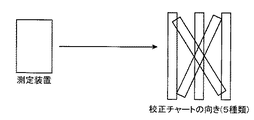
上記ユーザ校正における測定に際しては、測定装置と校正チャート(測定対象物)との位置関係を決める(位置決めを行う)必要がある。この測定装置と校正チャートとの位置関係は1つ又は複数のパターンに決められている。例えば、測定装置に校正チャートを正対させて近側位置、中央位置及び遠側位置とする場合、並びに測定装置に対して斜め上向き、斜め下向き、斜め右向き及び斜め左向きとする場合の合計7パターンの位置関係である。図15は、近側、中央及び遠側位置、並びに斜め上向き及び斜め下向きの5パターンの場合の位置関係を示している。
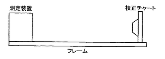
上記測定装置と校正チャートとの位置決めに関し、所定の支持部材例えばフレーム(校正チャートフレーム)に校正チャートと測定装置とを設置(固定)することで位置決めする方法、つまり冶具を用いた位置決め方法が知られている。しかしながらこの方法では、以下に示すような問題がある。 Regarding the positioning of the measuring device and the calibration chart, there is known a method of positioning by mounting (fixing) the calibration chart and the measuring device on a predetermined support member such as a frame (calibration chart frame), that is, a positioning method using a jig. It has been. However, this method has the following problems.
・校正チャートの設置場所に凹凸があると、校正チャートフレームが歪み、結果的に設置位置がずれて校正精度が悪くなることがある。
・測定装置をスタンド等に取り付けている場合、測定装置を該スタンドから一旦取り外してフレームに設置するのに手間がかかるとともに、落下等による破損の恐れもある。測定装置が重い場合には、当該測定装置の取り外しや設置に際して作業者に一層の負担をかけることになる。
・或る特定の姿勢(例えば正対姿勢)のみでの校正となるため、実際に測定するときと同じ姿勢で校正できない。すなわち姿勢が違うことによる装置各部材の撓みや歪みによる測定誤差(姿勢差;後述の実施形態における測定装置の発光部及び受光部間の基線長の変化による三角測量の誤差)が測定値に現れてしまう。
・フレームが長い場合には広い保管スペースが必要となる(図16参照)。
-If there is unevenness in the location where the calibration chart is installed, the calibration chart frame may be distorted, resulting in displacement of the installation position, resulting in poor calibration accuracy.
When the measuring device is attached to a stand or the like, it takes time to remove the measuring device from the stand and place it on the frame, and there is a risk of damage due to dropping or the like. When the measuring device is heavy, an additional burden is placed on the operator when removing and installing the measuring device.
-Since calibration is performed only in a specific posture (for example, a directly-facing posture), calibration cannot be performed in the same posture as when actually measuring. That is, a measurement error due to bending or distortion of each device member due to a different posture (posture difference; triangulation error due to a change in baseline length between the light emitting portion and the light receiving portion of the measuring device in an embodiment described later) appears in the measured value. End up.
・ If the frame is long, a large storage space is required (see FIG. 16).
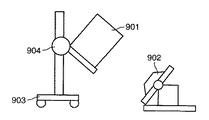
また、上記位置決めに関し、特許文献1には、図17に示すように、測定装置901により測定対象物902の2次元画像(モニタ画像)を取得し、ユーザがこの2次元画像上における或るポイントつまり基準点を指定すると、この基準点が測定装置の座標系の原点(中心点)に来るように、位置調整機構903及び角度調整機構904によって測定対象物902に対する測定装置901の位置及び角度が自動制御される技術が開示されている。しかしながらこの技術では、以下に示すような問題がある。
Regarding the above positioning, as shown in FIG. 17, in
・ユーザによる位置合わせ基準点の指定(この位置に合わせたいという指示)が作業手順に含まれており、位置合わせを自動的に行うことができない。
・形状が既知の立体測定物(測定対象物)を想定していない。
・複数の位置関係(斜め方向など)で校正するとき、校正チャートの周囲で測定装置を動かすつまり測定装置の場所を移動させたり姿勢や向きを変えなくてはならず、当該校正用に広いスペース(設置スペース或いは移動スペース)が必要になってしまう。
・複数の位置関係で校正するとき、測定装置を上述のように動かすため、実際に測定するときと同じ姿勢で校正できない(姿勢差が生じる)場合がある。
・2次元画像に対してポイントを指示する方法では、大まかな位置合わせは可能であっても、位置や角度を高精度に合わせることは難しい。
The work procedure includes designation of the alignment reference point by the user (instruction to align with this position), and the alignment cannot be performed automatically.
・ A solid measurement object (measurement object) with a known shape is not assumed.
・ When calibrating with multiple positional relationships (diagonal direction, etc.), the measurement device must be moved around the calibration chart, that is, the location of the measurement device must be moved and the orientation and orientation must be changed. (Installation space or movement space) is required.
-When calibrating with a plurality of positional relationships, the measuring device is moved as described above, and therefore, calibration may not be performed in the same posture as when actually measuring (an attitude difference occurs).
-In the method of instructing a point with respect to a two-dimensional image, although it is possible to roughly align, it is difficult to align the position and angle with high accuracy.
本発明は、上記事情に鑑みてなされたもので、広いスペースを必要とせず、また、ユーザが基準となる位置を指示する動作等を必要とせず容易に位置合わせすることが可能であるとともに、姿勢差の発生防止等により高精度に位置合わせすることが可能な位置合わせシステム及び位置合わせ方法を提供することを目的とする。 The present invention has been made in view of the above circumstances, does not require a wide space, and can be easily aligned without requiring an operation or the like for the user to indicate a reference position. An object of the present invention is to provide an alignment system and an alignment method capable of performing alignment with high accuracy by preventing occurrence of a posture difference or the like.
本発明に係る位置合わせシステムは、立体的な測定対象物である立体測定物と、前記立体測定物を非接触に3次元測定して該立体測定物の3次元データを取得する測定手段と、前記測定手段と前記立体測定物との位置合わせの基準となる基準情報を予め記憶する記憶手段と、前記3次元データと前記基準情報とに基づいて、前記測定手段の座標系における当該測定手段と立体測定物との相互の位置ずれ量及び角度ずれ量を算出するズレ量算出手段と、前記位置ずれ量及び角度ずれ量を前記位置合わせにおける調整動作用の調整パラメータに変換する変換手段と、前記調整パラメータに基づいて、前記立体測定物の位置及び角度を調整する調整手段とを備えることを特徴とする。 The alignment system according to the present invention includes a three-dimensional measurement object that is a three-dimensional measurement object, and a measurement unit that three-dimensionally measures the three-dimensional measurement object in a non-contact manner and acquires three-dimensional data of the three-dimensional measurement object; A storage unit that stores in advance reference information serving as a reference for alignment between the measurement unit and the three-dimensional measurement object; and the measurement unit in the coordinate system of the measurement unit based on the three-dimensional data and the reference information; A deviation amount calculating means for calculating a mutual positional deviation amount and an angular deviation amount with the three-dimensional measuring object, a conversion means for converting the positional deviation amount and the angular deviation amount into adjustment parameters for an adjustment operation in the alignment, and And adjusting means for adjusting the position and angle of the three-dimensional object based on the adjustment parameter.
上記構成によれば、測定手段によって、立体的な測定対象物である立体測定物が非接触に3次元測定されて該立体測定物の3次元データが取得される。また、記憶手段によって、測定手段と立体測定物との位置合わせの基準となる基準情報が予め記憶される。また、ズレ量算出手段によって、3次元データと基準情報とに基づいて測定手段の座標系における当該測定手段と立体測定物との相互の位置ずれ量及び角度ずれ量が算出される。そして、変換手段によって、位置ずれ量及び角度ずれ量が位置合わせにおける調整動作用の調整パラメータに変換され、調整手段によって、調整パラメータに基づいて立体測定物の位置及び角度が調整される。 According to the above configuration, the three-dimensional measurement object, which is a three-dimensional measurement object, is three-dimensionally measured in a non-contact manner by the measurement unit, and three-dimensional data of the three-dimensional measurement object is acquired. In addition, the storage unit stores in advance reference information that serves as a reference for alignment between the measurement unit and the three-dimensional object. Further, the displacement amount calculating means calculates the mutual positional deviation amount and angular deviation amount between the measuring means and the three-dimensional measuring object in the coordinate system of the measuring means based on the three-dimensional data and the reference information. Then, the conversion unit converts the positional deviation amount and the angular deviation amount into adjustment parameters for adjustment operation in alignment, and the adjustment unit adjusts the position and angle of the three-dimensional object based on the adjustment parameters.
また、上記構成において、前記立体測定物の姿勢を検出する姿勢検出手段をさらに備え、前記変換手段は、前記姿勢検出手段による姿勢検出情報を用いて前記測定手段の座標系と前記調整手段の座標系との関係を示す関係式を算出し、該関係式に基づく座標変換を行うことによって、前記測定手段の座標系における位置ずれ量及び角度ずれ量を、前記調整手段の座標系における前記調整パラメータに変換するようにしてもよい。(請求項2) Further, in the above configuration, the apparatus further includes an attitude detection unit that detects an attitude of the three-dimensional measurement object, and the conversion unit uses the attitude detection information obtained by the attitude detection unit and uses the coordinate system of the measurement unit and the coordinates of the adjustment unit. By calculating a relational expression indicating the relationship with the system and performing coordinate transformation based on the relational expression, the positional deviation amount and the angular deviation amount in the coordinate system of the measuring means are converted into the adjustment parameter in the coordinate system of the adjusting means. You may make it convert into. (Claim 2)
これによれば、姿勢検出手段によって、立体測定物の姿勢が検出される。そして、変換手段によって、姿勢検出手段による姿勢検出情報を用いて測定手段の座標系と調整手段の座標系との関係を示す関係式が算出され、該関係式に基づく座標変換が行われることによって、測定手段の座標系における位置ずれ量及び角度ずれ量が、調整手段の座標系における調整パラメータに変換される。 According to this, the posture of the three-dimensional object is detected by the posture detection means. Then, the conversion means calculates the relational expression indicating the relationship between the coordinate system of the measurement means and the coordinate system of the adjustment means using the posture detection information by the posture detection means, and performs coordinate conversion based on the relational expression. The positional deviation amount and the angular deviation amount in the coordinate system of the measuring means are converted into adjustment parameters in the coordinate system of the adjusting means.
また、上記構成において、前記立体測定物は、前記測定手段の校正を行うための、形状が既知である基準立体物であって、前記調整手段は、前記校正を行う前段階としての前記位置合わせを行うべく前記基準立体物の位置及び角度を調整するようにしてもよい。(請求項3) Further, in the above configuration, the three-dimensional object is a reference three-dimensional object having a known shape for calibrating the measuring unit, and the adjusting unit performs the alignment as a stage before performing the calibration. You may make it adjust the position and angle of the said reference | standard solid object in order to perform. (Claim 3)
これによれば、立体測定物が、測定手段の校正を行うための、形状が既知である基準立体物とされる。そして、調整手段によって、校正を行う前段階としての位置合わせを行うべく基準立体物の位置及び角度が調整される。 According to this, the three-dimensional object is a reference three-dimensional object with a known shape for calibrating the measuring means. Then, the position and angle of the reference three-dimensional object are adjusted by the adjusting means so as to perform alignment as a previous stage of calibration.
また、上記構成において、前記調整手段は、前記調整を行うべく前記調整パラメータに基づいて自動的に駆動する自動調整機構を備えるようにしてもよい。(請求項4) In the above configuration, the adjustment unit may include an automatic adjustment mechanism that is automatically driven based on the adjustment parameter to perform the adjustment. (Claim 4)
これによれば、調整手段が備える自動調整機構によって、調整を行うべく調整パラメータに基づいて自動的に駆動が行われる。 According to this, the automatic adjustment mechanism provided in the adjustment means automatically drives based on the adjustment parameter for adjustment.
また、上記構成において、前記調整パラメータに関する情報をユーザに報知する調整情報報知手段をさらに備え、前記調整手段は、前記調整を行うべく前記ユーザの手動操作によって駆動する手動調整機構を備えるようにしてもよい。(請求項5) Further, in the above configuration, adjustment information notification means for notifying a user of information relating to the adjustment parameter is further provided, and the adjustment means includes a manual adjustment mechanism that is driven by the user's manual operation to perform the adjustment. Also good. (Claim 5)
これによれば、調整情報報知手段によって、調整パラメータに関する情報がユーザに報知される。そして、調整手段が備える手動調整機構によって、調整を行うべくユーザの手動操作による駆動が行われる。 According to this, the information regarding the adjustment parameter is notified to the user by the adjustment information notification means. Then, driving by a user's manual operation is performed by a manual adjustment mechanism provided in the adjustment means to perform adjustment.
また、上記構成において、前記基準立体物は、角錐台状のものであるようにしてもよい。(請求項6) In the above configuration, the reference three-dimensional object may have a truncated pyramid shape. (Claim 6)
これによれば、基準立体物が角錐台状のものとされる。 According to this, the reference three-dimensional object has a truncated pyramid shape.
また、上記構成において、前記基準立体物は、所定の位置関係で配設された複数の球体からなるものであるようにしてもよい。(請求項7) In the above configuration, the reference three-dimensional object may be composed of a plurality of spheres arranged in a predetermined positional relationship. (Claim 7)
これによれば、基準立体物が所定の位置関係で配設された複数の球体からなるものとされる。 According to this, the reference solid object is composed of a plurality of spheres arranged in a predetermined positional relationship.
また、上記構成において、前記測定手段、ズレ量算出手段、変換手段、調整手段及び姿勢検出手段の少なくとも1つの手段について動作の異常を検出する異常検出手段と、
前記異常検出手段により異常が検出された場合に、該異常を示す情報をユーザに報知する異常報知手段とをさらに備えるようにしてもよい。(請求項8)
Further, in the above configuration, an abnormality detection unit that detects an abnormality in operation of at least one of the measurement unit, the deviation amount calculation unit, the conversion unit, the adjustment unit, and the posture detection unit;
When an abnormality is detected by the abnormality detection unit, an abnormality notification unit that notifies the user of information indicating the abnormality may be further provided. (Claim 8)
これによれば、異常検出手段によって、測定手段、ズレ量算出手段、変換手段、調整手段及び姿勢検出手段の少なくとも1つの手段について動作の異常が検出される。そして、異常報知手段によって、異常検出手段により異常が検出された場合に、該異常を示す情報がユーザに報知される。 According to this, an abnormality in operation is detected by at least one of the measuring means, the deviation amount calculating means, the converting means, the adjusting means, and the posture detecting means by the abnormality detecting means. Then, when an abnormality is detected by the abnormality detection unit, the abnormality notification unit notifies the user of information indicating the abnormality.
また、上記構成において、前記位置合わせシステムは、前記測定手段である測定装置と、前記立体測定物と、該立体測定物の位置及び角度を変化させることが可能に支持する前記調整手段とからなる被測定装置と、前記記憶手段、ズレ量算出手段及び変換手段を内蔵するとともに、前記測定装置及び被測定装置それぞれと通信可能に接続された情報処理装置とからなるものであるようにしてもよい。(請求項9) Further, in the above configuration, the alignment system includes a measuring device that is the measuring unit, the three-dimensional object, and the adjusting unit that supports the position and angle of the three-dimensional object so as to be changed. The apparatus to be measured and the storage means, the deviation amount calculating means, and the converting means may be incorporated, and the apparatus to be measured may be configured to include an information processing apparatus that is communicably connected to the measurement apparatus and the device to be measured. . (Claim 9)
これによれば、位置合わせシステムが、測定手段である測定装置と、立体測定物と、該立体測定物の位置及び角度を変化させることが可能に支持する調整手段とからなる被測定装置と、記憶手段、ズレ量算出手段及び変換手段を内蔵するとともに、測定装置及び被測定装置それぞれと通信可能に接続された情報処理装置とからなるものとされる。 According to this, the apparatus to be measured includes a measuring device that is a measuring unit, a three-dimensional object, and an adjustment unit that supports the three-dimensional object so that the position and angle of the three-dimensional object can be changed, and The information processing apparatus includes a storage unit, a deviation amount calculation unit, and a conversion unit, and an information processing apparatus that is communicably connected to the measurement apparatus and the measurement target apparatus.
また、本発明に係る位置合わせ方法は、立体的な測定対象物である立体測定物を非接触に3次元測定して該立体測定物の3次元データを取得する第1の工程と、前記立体測定物を測定する測定手段と該立体測定物との位置合わせの基準となる基準情報を予め取得する第2の工程と、前記3次元データと前記基準情報とに基づいて、前記測定手段の座標系における当該測定手段と立体測定物との相互の位置ずれ量及び角度ずれ量を算出する第3の工程と、前記位置ずれ量及び角度ずれ量を前記位置合わせにおける調整動作用の調整パラメータに変換する第4の工程と、前記調整パラメータに基づいて、前記立体測定物の位置及び角度を調整する第5の工程とを有することを特徴とする。(請求項10) In addition, the alignment method according to the present invention includes a first step of three-dimensionally measuring a three-dimensional measurement object that is a three-dimensional measurement object to obtain three-dimensional data of the three-dimensional measurement object; Based on the second step of acquiring in advance the reference information that serves as a reference for alignment between the measuring means for measuring the measuring object and the three-dimensional measuring object, and the coordinates of the measuring means based on the three-dimensional data and the reference information A third step of calculating a mutual positional deviation amount and an angular deviation amount between the measuring means and the three-dimensional object in the system, and converting the positional deviation amount and the angular deviation amount into adjustment parameters for an adjustment operation in the alignment. And a fifth step of adjusting the position and angle of the three-dimensional object based on the adjustment parameter. (Claim 10)
これによれば、第1の工程において、立体的な測定対象物である立体測定物が非接触に3次元測定されて該立体測定物の3次元データが取得される。第2の工程において、立体測定物を測定する測定手段と該立体測定物との位置合わせの基準となる基準情報が予め取得される。また、第3の工程において、3次元データと基準情報とに基づいて、測定手段の座標系における当該測定手段と立体測定物との相互の位置ずれ量及び角度ずれ量が算出される。そして、第4の工程において、位置ずれ量及び角度ずれ量が位置合わせにおける調整動作用の調整パラメータに変換され、第5の工程において、調整パラメータに基づいて、立体測定物の位置及び角度が調整される。 According to this, in the first step, the three-dimensional measurement object which is a three-dimensional measurement object is three-dimensionally measured in a non-contact manner, and three-dimensional data of the three-dimensional measurement object is acquired. In the second step, reference information serving as a reference for alignment between the measuring means for measuring the three-dimensional object and the three-dimensional object is acquired in advance. In the third step, based on the three-dimensional data and the reference information, the mutual positional deviation amount and angular deviation amount between the measuring means and the three-dimensional measuring object in the coordinate system of the measuring means are calculated. Then, in the fourth step, the positional deviation amount and the angular deviation amount are converted into adjustment parameters for adjustment operation in alignment, and in the fifth step, the position and angle of the three-dimensional measurement object are adjusted based on the adjustment parameters. Is done.
また、上記構成において、前記立体測定物の姿勢を検出する第6の工程をさらに有し、前記第4の工程は、前記第6の工程において検出された姿勢検出情報を用いて前記測定手段の座標系と、前記調整を行う調整手段の座標系との関係を示す関係式を算出し、該関係式に基づく座標変換を行うことによって、前記測定手段の座標系における位置ずれ量及び角度ずれ量を、前記調整手段の座標系における前記調整パラメータに変換する工程であるようにしてもよい。(請求項11) Further, in the above configuration, the method further includes a sixth step of detecting the posture of the three-dimensional object, and the fourth step uses the posture detection information detected in the sixth step. By calculating a relational expression showing the relationship between the coordinate system and the coordinate system of the adjusting means for performing the adjustment, and performing coordinate conversion based on the relational expression, the positional deviation amount and the angular deviation amount in the coordinate system of the measuring means May be converted into the adjustment parameter in the coordinate system of the adjustment means. (Claim 11)
これによれば、第6の工程において、立体測定物の姿勢が検出される。そして、第4の工程において、第6の工程において検出された姿勢検出情報を用いて測定手段の座標系と、調整を行う調整手段の座標系との関係を示す関係式が算出され、該関係式に基づく座標変換が行われることによって、測定手段の座標系における位置ずれ量及び角度ずれ量が、調整手段の座標系における調整パラメータに変換される。 According to this, the posture of the three-dimensional object is detected in the sixth step. In the fourth step, a relational expression indicating the relationship between the coordinate system of the measuring unit and the coordinate system of the adjusting unit that performs adjustment is calculated using the posture detection information detected in the sixth step, and the relationship By performing coordinate conversion based on the equation, the positional deviation amount and the angular deviation amount in the coordinate system of the measuring means are converted into adjustment parameters in the coordinate system of the adjusting means.
請求項1に係る位置合わせシステムによれば、測定手段と立体測定物との位置合わせが、調整手段による立体測定物の位置及び角度の調整により行われるので、すなわち当該位置合わせが、測定手段を動かさずに、立体測定物を動かすことによって行われるので、広いスペース(設置スペース或いは移動スペース)を必要とすることなく位置合わせすることができる。また、3次元データと基準情報とに基づいて測定手段と立体測定物との相互の位置ずれ量及び角度ずれ量が自動的に算出されるので、ユーザが基準となる位置を指示する動作が必要がなく、容易に位置合わせすることができる。位置ずれ量及び角度ずれ量が調整手段の調整パラメータに変換されることからも、この調整パラメータを用いて、当該位置合わせのための調整作業が例えば自動駆動、手動操作いずれで行う場合にも容易に行えるようになる。また、測定手段を動かさずに(位置や向きを変えることなく)、実際に測定するのと同じ姿勢を保った状態で当該位置合わせが行われるため、姿勢差の発生を防止することができ、ひいては高精度な位置合わせが可能となる。測定手段による立体測定物の3次元測定により3次元データが取得される、すなわち調整手段による調整動作において立体測定物の3次元データが用いられることからも(2次元データを用いた位置合わせを行う場合と比べて)、高精度な位置合わせが可能となる。 According to the alignment system of the first aspect, since the alignment between the measuring means and the three-dimensional object is performed by adjusting the position and angle of the three-dimensional object by the adjusting means, that is, the alignment is performed on the measuring means. Since it is performed by moving the three-dimensional object without moving, it can be aligned without requiring a large space (installation space or moving space). Also, since the mutual displacement amount and angular displacement amount between the measuring means and the three-dimensional object are automatically calculated based on the three-dimensional data and the reference information, the user needs to indicate the reference position. And can be easily aligned. Since the positional deviation amount and the angular deviation amount are converted into the adjustment parameters of the adjustment means, it is easy to use this adjustment parameter when the adjustment work for the alignment is performed by, for example, automatic driving or manual operation. Will be able to do. In addition, since the positioning is performed while maintaining the same posture as that actually measured without moving the measuring means (without changing the position or orientation), it is possible to prevent the occurrence of a posture difference, As a result, highly accurate alignment is possible. The three-dimensional data is acquired by the three-dimensional measurement of the three-dimensional object by the measuring means, that is, the three-dimensional data of the three-dimensional object is used in the adjustment operation by the adjusting means (alignment using two-dimensional data is performed). Compared to the case), highly accurate alignment is possible.
請求項2に係る位置合わせシステムによれば、測定手段座標系における位置ずれ量及び角度ずれ量が、該測定手段座標系と調整手段座標系との関係に基づく座標変換によって調整手段座標系における調整パラメータに変換されるので、測定手段側で求めた位置ずれ量及び角度ずれ量を、調整手段側での位置ずれ量及び角度ずれ量として扱うことができるようになる。これにより、測定手段を動かすことなく立体測定物の方を動かして当該位置合わせする構成を実現することができ、ひいては広いスペースを必要とせず、容易且つ高精度に位置合わせすることが可能となる。 According to the alignment system of claim 2, the positional deviation amount and the angular deviation amount in the measuring means coordinate system are adjusted in the adjusting means coordinate system by coordinate conversion based on the relationship between the measuring means coordinate system and the adjusting means coordinate system. Since it is converted into a parameter, the positional deviation amount and the angular deviation amount obtained on the measuring means side can be handled as the positional deviation amount and the angular deviation amount on the adjusting means side. As a result, it is possible to realize a configuration in which the three-dimensional object is moved and moved without moving the measuring means, and therefore, it is possible to align easily and with high accuracy without requiring a wide space. .
請求項3に係る位置合わせシステムによれば、位置合わせシステムを、基準立体物を用いて測定手段の校正を行う校正システムとして使用することができる。 According to the alignment system of the third aspect, the alignment system can be used as a calibration system that calibrates the measuring means using the reference three-dimensional object.
請求項4に係る位置合わせシステムによれば、調整手段による調整動作を自動調整機構によって自動的に行うことができ、測定手段と立体測定物との位置合わせが一層容易に行えるようになる。 According to the alignment system of the fourth aspect, the adjustment operation by the adjustment means can be automatically performed by the automatic adjustment mechanism, and the alignment between the measurement means and the three-dimensional object can be performed more easily.
請求項5に係る位置合わせシステムによれば、調整手段による調整動作をユーザによる手動調整機構を用いた手動操作によって行うことができ、ひいては測定手段と立体測定物との位置合わせ動作における自由度が高くなる。 According to the alignment system of the fifth aspect, the adjustment operation by the adjustment unit can be performed manually by the user using the manual adjustment mechanism, and as a result, the degree of freedom in the alignment operation between the measurement unit and the three-dimensional object is increased. Get higher.
請求項6に係る位置合わせシステムによれば、角錐台状の簡易な形状の基準立体物を用いて、容易に且つ精度良く位置ずれ量及び角度ずれ量を求めて当該位置合わせを行うことができるとともに、この基準立体物を用いて、位置合わせ後の校正を容易に且つ精度良く行うことができる。 According to the alignment system of the sixth aspect, it is possible to easily and accurately obtain the positional deviation amount and the angular deviation amount using the reference solid object having a simple truncated pyramid shape and perform the alignment. At the same time, using this reference three-dimensional object, calibration after alignment can be performed easily and accurately.
請求項7に係る位置合わせシステムによれば、所定の位置関係で配設された複数の球体からなる簡易な形状の基準立体物を用いて、容易に且つ精度良く位置ずれ量及び角度ずれ量を求めて当該位置合わせを行うことができるとともに、この基準立体物を用いて、位置合わせ後の校正を容易に且つ精度良く行うことができる。 According to the alignment system according to claim 7, the amount of positional deviation and the amount of angular deviation can be easily and accurately determined using a simple three-dimensional reference solid object composed of a plurality of spheres arranged in a predetermined positional relationship. The positioning can be performed and the calibration can be performed easily and accurately after the positioning using the reference three-dimensional object.
請求項8に係る位置合わせシステムによれば、異常報知手段により異常情報が報知されることで、位置合わせシステムの動作(位置合わせの動作)に異常が発生していることをユーザが容易に知ることができる。 According to the alignment system of the eighth aspect, the abnormality information is notified by the abnormality notification unit, so that the user can easily know that an abnormality has occurred in the operation of the alignment system (alignment operation). be able to.
請求項9に係る位置合わせシステムによれば、位置合わせシステムを、測定装置、被測定装置及び情報処理装置からなるシンプルな構成のシステムとすることができる。 According to the alignment system of the ninth aspect, the alignment system can be a system having a simple configuration including a measuring device, a device under measurement, and an information processing device.
請求項10に係る位置合わせ方法によれば、測定手段と立体測定物との位置合わせが、立体測定物の位置及び角度の調整により行われるので、すなわち当該位置合わせが、測定手段を動かさずに、立体測定物を動かすことによって行われるので、広いスペース(設置スペース或いは移動スペース)を必要とすることなく位置合わせすることができる。また、3次元データと基準情報とに基づいて測定手段と立体測定物との相互の位置ずれ量及び角度ずれ量が自動的に算出されるので、ユーザが基準となる位置を指示する動作が必要がなく、容易に位置合わせすることができる。位置ずれ量及び角度ずれ量が調整動作用の調整パラメータに変換されることからも、この調整パラメータを用いて、当該位置合わせのための調整作業が例えば自動駆動、手動操作いずれで行う場合にも容易に行えるようになる。また、測定手段を動かさずに(位置や向きを変えることなく)、実際に測定するのと同じ姿勢を保った状態で当該位置合わせが行われるため、姿勢差の発生を防止することができ、ひいては高精度な位置合わせが可能となる。測定手段による立体測定物の3次元測定により3次元データが取得される、すなわち立体測定物の位置及び角度の調整動作において立体測定物の3次元データが用いられることからも(2次元データを用いた位置合わせを行う場合と比べて)、高精度な位置合わせが可能となる。 According to the alignment method of the tenth aspect, the alignment between the measuring means and the three-dimensional object is performed by adjusting the position and angle of the three-dimensional object, that is, the alignment does not move the measuring means. Since it is performed by moving the three-dimensional object, alignment can be performed without requiring a large space (installation space or movement space). Also, since the mutual displacement amount and angular displacement amount between the measuring means and the three-dimensional object are automatically calculated based on the three-dimensional data and the reference information, the user needs to indicate the reference position. And can be easily aligned. Since the positional deviation amount and the angular deviation amount are converted into the adjustment parameters for the adjustment operation, this adjustment parameter is used to perform the adjustment work for the alignment by either automatic driving or manual operation, for example. It becomes easy to do. In addition, since the positioning is performed while maintaining the same posture as that actually measured without moving the measuring means (without changing the position or orientation), it is possible to prevent the occurrence of a posture difference, As a result, highly accurate alignment is possible. The three-dimensional data is acquired by the three-dimensional measurement of the three-dimensional object by the measuring means, that is, the three-dimensional data of the three-dimensional object is used in the adjustment operation of the position and angle of the three-dimensional object (using the two-dimensional data). Compared with the case where the alignment is performed), highly accurate alignment is possible.
請求項11に係る位置合わせ方法によれば、測定手段座標系における位置ずれ量及び角度ずれ量が、該測定手段座標系と調整手段座標系との関係に基づく座標変換によって調整手段座標系における調整パラメータに変換されるので、測定手段側で求めた位置ずれ量及び角度ずれ量を、調整手段側での位置ずれ量及び角度ずれ量として扱うことができるようになる。これにより、測定手段を動かすことなく立体測定物の方を動かして当該位置合わせする構成を実現することができ、ひいては広いスペースを必要とせず、容易且つ高精度に位置合わせすることが可能となる。 According to the alignment method of the eleventh aspect, the positional deviation amount and the angular deviation amount in the measurement unit coordinate system are adjusted in the adjustment unit coordinate system by coordinate conversion based on the relationship between the measurement unit coordinate system and the adjustment unit coordinate system. Since it is converted into a parameter, the positional deviation amount and the angular deviation amount obtained on the measuring means side can be handled as the positional deviation amount and the angular deviation amount on the adjusting means side. As a result, it is possible to realize a configuration in which the three-dimensional object is moved and moved without moving the measuring means, and therefore, it is possible to align easily and with high accuracy without requiring a wide space. .
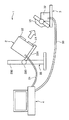
図1は、本実施形態に係る位置合わせシステムの一例である3次元測定システム1の概略構成図である。3次元測定システム1は、測定装置2、校正装置3及び情報処理装置4を備えている。測定装置2は、測定対象物を接触することなく3次元測定する所謂非接触3次元測定装置である。測定装置2は、測定装置2の前面(後述の校正チャートに対向させる面)に投光部21及び受光部22を備えており、投光部21から射出した所定の光(光線)によって測定対象物(後述の校正チャート)を照射し、この照射光による測定対象物からの反射光を受光部22により受光して信号(受光信号)に変換することにより該測定対象物の3次元的な測定情報(3次元測定データ)を取得する。測定装置2によるこの3次元測定は、所謂三角測量の原理に基づく測定である。
FIG. 1 is a schematic configuration diagram of a three-
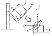
測定装置2は、所定の支持台例えばスタンド23を備えており、このスタンド23に固定されている。スタンド23は、測定装置2を支持するフレーム体231、及び当該測定装置2が支持されたフレーム体231を例えばスタンド本体232に対してその回動を規制することで所定の向き(図1では斜め下向き)に固定する固定具233などを備えてなる。ところで、測定装置2の座標系(測定装置座標系という)は、測定装置2側で定義したローカル座標系である。このローカル座標系をワールド座標系で見た場合、図2(a)〜(c)に示すように、測定装置2の姿勢が変化するとこれに伴い測定装置座標系の向きも変化する。ここでは測定装置座標系として、測定装置2における上記前面の面内にX−Y軸を定める(ここでは図2(a)中の手前側に向かってX軸、図2(a)中の上側に向かってY軸と定める)とともに、この前面の反対側(後方側)に向かってZ軸を定める。なお、測定装置2は情報処理装置4と通信ケーブル24によって接続されており、情報処理装置4との間のデータの送受信が可能とされている。なお、測定装置2の電源は測定装置2内に備えたものであってもよいし、所定の外部電源でもよい。
The measuring device 2 includes a predetermined support base such as a
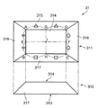
校正装置3は、測定装置2による測定対象物の測定に関する該測定装置2の校正を行うためのものである。3次元測定システム1において、校正装置3は該校正装置3の校正チャート31が測定装置2と向かい合うように配置されている。校正装置3は、校正チャート31及び位置角度調整機構32を備えている。校正チャート31は、例えば図3に示すような当該校正において用いる所定の基準となる立体物(基準立体物;本実施形態ではこれを「校正チャート」という)である。
The
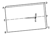
図3における符号311で示す図は、校正チャート31における前記測定装置2の前面に対向する面の平面図であり、符号312で示す図は側面図である。校正チャート31は角錐(ここでは4角錐)の頭が切り欠かれてなる所謂角錐台の形状をしたもの、換言すれば平面視が四角形である台形状の立体(台形体という)である。詳細には、長方形の底面313と、該底面313に平行な長方形の頂面314と、該頂面314の四辺に接した台形の4つの側面315〜318とで囲まれた立体をしている。ただし、校正チャート31は同図に示す台形体に限定されず、例えば平面視が正方形の台形体であってもよい。なお、頂面314における辺AB、BC、CD及びDAそれぞれの中点E、H、F及びGを定めたときの線EFと線GGとの交点を点Iと定める(頂面314の対角線AC及びBDの交点を点Iとしてもよい)。また、校正チャート31の頂面314を、点ABCDで囲まれてなる「平面ABCD」と適宜表現する。
3 is a plan view of the surface of the
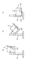
位置角度調整機構32は、校正チャート31を支持するとともに該校正チャート31の測定装置2に対する位置や角度を調整するもの(機構)である。位置角度調整機構32の詳細を説明する前に先ず、校正装置3における座標系について説明する。校正装置3の座標系(校正装置座標系という)は、謂わば固定されたワールド座標系と同等の座標系(ワールド座標系)である。ここでは、この固定されたワールド座標系として、図4中の左上に概略的に記載した校正装置3に示すように、水平方向で且つ上記頂面314側に向かってZ軸を、鉛直方向上向きにY軸を、これらY軸及びZ軸によるY−Z平面に対して垂直で且つ紙面の手前側へ向かってX軸を定める。
The position
位置角度調整機構32は、X、Y及びZ軸方向の平行移動と、X、Y及びZ軸回りの回転移動(X軸回転;ピッチ、Y軸回転;ヨー、Z軸回転;ロール)との合計6つの自由度での校正チャート31の移動(位置・角度調整)が可能に構成されている。すなわち位置角度調整機構32は、校正チャート31を載置(位置固定)する略平板状の載置台321と、校正チャート31が載置された載置台321をX軸回転させる一対のX軸回転部322と、載置台321をZ軸回転させるZ軸回転部323と、載置台321をY軸回転させるY軸回転部324と、載置台321をY軸、X軸、Z軸方向に平行移動させるそれぞれY軸移動部325とX軸移動部326とZ軸移動部327と、載置台321を当該X、Y、Z軸回転及びY軸平行移動可能に支持する支持フレーム328と、基台329とを備えている。ただし、X軸移動部326及びZ軸移動部327は、それぞれ基台329に対して例えばスライド移動が可能なスライドレール機構を備えた構成となっており、また、Y軸移動部325は基台329に対して鉛直方向の上下移動が可能な例えばジャッキ機構を備えた構成となっている。なお、上記X、Y及びZ軸回転の各回転軸は全て校正装置座標系の原点(校正チャート31の中央(中心)部;後述する点I)を通るように設計されている。
The position
上記各部322〜327にはモータ(例えばサーボモータ)等の駆動部(駆動源、駆動機構)が設けられており、この駆動部によって各座標軸に対する回転移動や平行移動を行うことができるようになっている。ただし、駆動部は当該回転や平行移動を可能とするのであれば任意の構成及び動作方法が採用可能である。これにより、各部322〜327は、後述する情報処理装置4から送信されてきた調整パラメータ分だけすなわち調整パラメータに対応する回転量及び平行移動量だけ自動的に駆動される。この駆動により、相対する校正チャート31と測定装置2との位置合わせ(原点合わせ)が行われる。ここで、「位置合わせ」という言葉について定義しておく。相対するつまり対向配置された2者間の“ずれ”を考える場合、この“ずれ”には、位置的(距離的)なずれ(これを「位置ずれ」という)と、角度的な(向く方向の)ずれ(これを「角度ずれ」という)との意味が含まれる。すなわち、「位置合わせ」は、これら「位置ずれ」及び「角度ずれ」が無くなるように調整して合わせることである(「位置合わせ」における“位置”と、「位置ずれ」における“位置”とは違う意味である)。
Each of the
かかる位置合わせにおける実際の動作では、先ず“回転”によって角度ずれを調整する。位置角度調整機構32では、当該回転はY軸回転、Z軸回転、X軸回転の順で行われる。すなわち最初にY軸回りにθ回転(これを回転行列Yθで定義する)した後、この回転後のZ軸回りにφ回転(これを回転行列Zφで定義する)し、さらにこの回転後のX軸回りにψ回転(これを回転行列Xψで定義する)する。そして、当該回転させることによって角度ずれを調整した後、平行移動させることによって位置ずれを調整する。この平行移動における移動量を(lx,ly,lz)として、行列Lで定義する。
In the actual operation in such alignment, first, the angular deviation is adjusted by “rotation”. In the position
上記回転行列Yθ、Zφ、Xψ及び行列Lは、それぞれ以下の(1)〜(4)式で表される。

The rotation matrices Y θ , Z φ , X ψ and the matrix L are expressed by the following equations (1) to (4), respectively.
上記記回転行列Yθ、Zφ、Xψ及び行列Lによる一連の座標変換行列を「M」とすると、以下の(5)式で表すことができる。
M=Yθ・Zφ・Xψ・L ・・・(5)
Assuming that a series of coordinate transformation matrices based on the rotation matrix Y θ , Z φ , X ψ and the matrix L is “M”, it can be expressed by the following equation (5).
M = Y θ · Z φ · X ψ · L (5)
上記座標変換行列Mによる座標変換前の座標を(xa,ya,za)、座標変換後の座標を(xb,yb,zb)とし、また、Pa=(xa,ya,za,1)、Pb=(xb,yb,zb,1)とおくと、以下の(6)式となる。
Pb=M・Pa ・・・(6)
The coordinates before the coordinate conversion by the coordinate conversion matrix M are (xa, ya, za), the coordinates after the coordinate conversion are (xb, yb, zb), and Pa = (xa, ya, za, 1), Pb = (Xb, yb, zb, 1), the following equation (6) is obtained.
Pb = M · Pa (6)
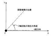
位置角度調整機構32は、校正チャート31の姿勢を検出する姿勢検出手段の役割も兼ねている。すなわち、位置角度調整機構32(X軸回転部322、Z軸回転部323及びY軸回転部324)による回転移動については、調整機構の現在の角度絶対値を読み取ることもできるようにしておけば、校正チャート31のワールド座標系における姿勢も検出することができる。例えば、上記Z軸回転の場合であれば、図5に示すようにXY平面の例えばX軸方向を、当該Z軸回転における回転角度の絶対的な基準である例えば0(ゼロ)度であるとする。そしてこの基準角度位置からどれくらいの角度だけ回転しているかを示す回転量(上記角度絶対値)を検出することで、現在、校正チャート31がどれくらい傾いているかといった姿勢を検出することが可能である。
The position
位置角度調整機構32は、当該回転量を検出する検出部つまり姿勢検出センサを各回転部322〜324に備えており、各回転部322〜324の駆動に応じてこの姿勢検出センサによって、例えば、上記基準角度位置(0度)からどれくらいの量(絶対量)だけ回転しているかを示す目盛り値(ゲージ値)の情報を自動的に検出する(読み取る)構成であってもよい。このようにして、X軸、Y軸及びZ回転それぞれの角度絶対値(ψ0,φ0,θ0)が求まる。この姿勢検出センサによって検出された情報(これを姿勢検出情報という)は、情報処理装置4へ出力される。
The position
なお、位置角度調整機構32は、各回転部322〜324における姿勢検出センサだけでなく、各移動部325〜327においても、当該平行移動における平行移動量を検出するセンサを備えていてもよい。さらに、校正装置3すなわち各部322〜327の駆動部や検出部は情報処理装置4と通信ケーブル33によって接続されており、情報処理装置4との間のデータの送受信が可能となっている。また、上記各駆動部や検出部の電源は、校正装置3内に備えたものであってもよいし、情報処理装置4内の電源或いは所定の外部電源でもよい。
Note that the position
情報処理装置4は、測定装置2と校正チャート31との位置合わせをするべく、測定装置2に校正チャート31を3次元測定させるとともに、測定装置2による測定により得られた測定データに基づいて校正装置3を制御する、すなわち校正チャート31の位置や角度(姿勢)を調整するための駆動動作や姿勢検出動作を制御するものである。ここでは、情報処理装置4は例えばPC(Personal Computer)である。
The information processing apparatus 4 causes the measurement apparatus 2 to measure the
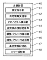
情報処理装置4は、情報処理装置4の制御プログラムを記憶するROM(Read Only Memory)、一時的にデータを保管するRAM(Random Access Memory)、及びこの制御プログラム等をROMから読み出して実行するマイクロコンピュータ等からなる主制御部40を備えており、この主制御部40によって上記駆動動作や姿勢検出動作の制御を行う。図6は、主制御部40の一例を示す機能ブロック図である。同図に示すように主制御部40は、測定指示部41、測定情報受信部42、ずれベクトル算出部43、姿勢検出情報受信部44、調整パラメータ算出部45、調整パラメータ送信部46、基準情報記憶部47及びエラー報知部48を備えている。
The information processing apparatus 4 includes a ROM (Read Only Memory) that stores a control program of the information processing apparatus 4, a RAM (Random Access Memory) that temporarily stores data, and a micro that reads the control program from the ROM and executes it. A
測定指示部41は、測定装置2に対する、校正チャート31の3次元測定を開始させるとともに、測定終了後に該3次元測定による測定情報を送信してくるよう指示する信号(通信コマンド)を出力するものである。測定情報受信部42は、測定装置2から送信されてきた3次元測定データ(測定情報)を受信するものである。
The
ずれベクトル算出部43は、測定情報受信部42により受信した3次元測定データに基づいて、測定装置座標系での校正チャート31の位置ずれ量及び角度ずれ量に関する「ずれベクトル」を算出するものである。ここでのずれベクトルは、謂わば、後述の調整パラメータ算出部45での位置ずれ量及び角度ずれ量の算出の前段階として、該位置ずれ量及び角度ずれ量を測定装置座標系における“ベクトル量”として定義するものである。なお、ここで算出されたずれベクトルは後述の調整パラメータ算出部45によりワールド座標系に変換され、位置角度調整機構32でのX、Y、Z軸回転、平行移動の各種調整パラメータが求められる。
The deviation
<位置ずれベクトルの算出>
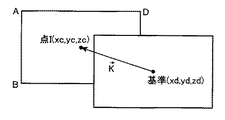
ずれベクトル算出部43は、3次元測定データから測定装置座標系での点Iの座標位置(I座標;図3参照)を算出し、このI座標と予め記憶されている基準座標とを比較して、基準座標に対するI座標のずれ量をベクトル(方向ベクトル)として算出する。この基準座標に対するI座標の“ずれ”を測定装置座標系でのXYZ軸方向全体で見た場合のずれと考えて、「XYZ位置ずれ」とも表現する。図7に示すように、上記I座標を(xc,yc,zc)とし、また、このI座標が本来あるべき基準座標、すなわち位置合わせが正しく行われている場合の理想(位置合わせの目標)とする座標を(xd,yd,zd)とすると、XYZ位置ずれベクトルKは以下の(7)式で表される。ただし、この“K”は図7中のKベクトルを示している。なお、校正チャート31が測定装置2の画角中央(撮影画像の中心)に位置する場合は、XYZ位置ずれベクトルKがZ軸と一致するため、xd=yd=0となる、すなわち基準座標は(0,0,zd)となる。
(kx,ky,kz)=(xc−xd,yc−yd,zc−zd) ・・・(7)
<Calculation of displacement vector>
The deviation
(Kx, ky, kz) = (xc−xd, yc−yd, zc−zd) (7)
<角度ずれベクトルの算出>
角度ずれベクトルの算出方法は、X及びY軸に対するつまりX及びY軸で構成されるX−Y平面で考えた場合(所謂「あおり」を考えた場合)の角度ずれベクトル(XY軸角度ずれベクトルという)と、Z軸に対するつまりZ軸回りで考えた場合の角度ずれベクトル(Z軸角度ずれベクトル)とで区別される。
[XY軸角度ずれベクトルの算出]
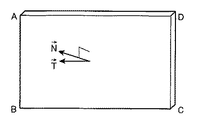
ずれベクトル算出部43は、3次元測定データから測定装置座標系における校正チャート31の頂面314の法線ベクトル(測定法線ベクトルNという)を算出するとともに、予め記憶されている上記位置合わせが正しく行われている場合の理想(位置合わせの目標)とする平面(基準平面;理想平面)の法線ベクトル(基準法線ベクトルTという)を取得する。ずれベクトル算出部43は、図8に示すように、これら測定法線ベクトルN=(nx,ny,nz)と基準法線ベクトルT=(tx,ty,tz)とを、XY軸角度ずれベクトルとして設定(定義)する。なお、図8中のNベクトル及びTベクトルは当該“N”及び“T”を示している。
<Calculation of angular deviation vector>
The calculation method of the angle deviation vector is an angle deviation vector (XY axis angle deviation vector) when considered on the XY plane composed of the X and Y axes with respect to the X and Y axes (so-called “tilt” is considered). And an angle deviation vector (Z-axis angle deviation vector) when considered about the Z-axis, that is, around the Z-axis.
[Calculation of XY axis angular deviation vector]
The deviation
上記測定法線ベクトルの具体的な算出方法は、3次元測定データから測定装置座標系における校正チャート31の点A、B、C及びDの座標を算出するとともに、算出したこれらABCD4点の座標情報に基づいてすなわち四角形ABCDを平面近似することで平面ABCDを求める。そしてこの平面ABCDから測定法線ベクトルNを算出する(後述の変形態様における球の場合の校正チャートでは該球の下の平面部分を平面近似する)。なお、上記3次元測定データから点A、B、C、Dの座標を算出する方法は、具体的には例えば点Aの場合、図3に示すように頂面314と側面315及び側面316との3つの平面の式を求めておき、この3つの平面の交点(3次元座標点)求めるようにすればよい。なお、基準平面が測定装置に正対したものであるとする場合には、基準法線ベクトルTはZ軸方向の単位方向ベクトルと同じ(0,0,1)となる。
The specific calculation method of the measurement normal vector is to calculate the coordinates of the points A, B, C and D of the
[Z軸角度ずれベクトルの算出]
また、ずれベクトル算出部43は、3次元測定データから測定装置座標系における校正チャート31の頂面314の水平方向ベクトル(測定方向ベクトルRという)を算出するとともに、予め記憶されている上記位置合わせが正しく行われている場合の理想(位置合わせの目標)とする方向(基準方向;理想方向)のベクトル(基準方向ベクトルSという)を取得する。ずれベクトル算出部43は、図9に示すように、これら測定方向ベクトルR=(rx,ry,rz)と基準方向ベクトルS=(sx,sy,sz)とを、Z軸角度ずれベクトルとして設定(定義)する。なお、図9中のRベクトル及びSベクトルは当該“R”及び“S”を示している。
[Calculation of Z-axis angle deviation vector]
Further, the deviation
上記測定方向ベクトルの具体的な算出方法は、3次元測定データから測定装置座標系における校正チャート31の点A、B、C及びDの座標を算出するとともに、算出したこれらABCD4点の座標情報に基づいて上記図3に示すように中点E、Fの座標を算出し、この2点E、Fの座標情報から測定方向ベクトルRを算出する(後述の変形態様における球の場合の校正チャートでは該球の下の平面部分の同中点から求める)。ただし、測定方向ベクトルは必ずしも中点E、Fから求めずともよく、例えば中点G、H或いはこれ以外の点から求めてもよい。上記ABCD4点から平面ABCDを求め、この平面ABCD内の任意の2点から測定方向ベクトルを求めるなど任意な方法が採用可能である。この場合も、上記基準平面が測定装置に正対したものであるとする場合には、基準方向ベクトルSはX軸方向の単位方向ベクトルと同じ(1,0,0)となる。
The specific calculation method of the measurement direction vector is to calculate the coordinates of the points A, B, C and D of the
姿勢検出情報受信部44は、位置角度調整機構32(各回転部322〜324)の姿勢検出センサにより検出されて出力された校正チャート31の姿勢検出情報、例えば上述した校正装置座標系でのX軸、Y軸及びZ回転それぞれの角度絶対値(ψ0,φ0,θ0)の情報を受信するものである。
The posture detection
調整パラメータ算出部45は、位置角度調整機構32における当該位置合わせに関する調整駆動に用いる調整パラメータを算出するものである。調整パラメータ算出部45は、姿勢検出情報受信部44により受信された姿勢検出情報を用いて、ずれベクトル算出部43により算出されたずれベクトルを測定装置座標系から校正装置座標系に変換し、この変換情報から調整パラメータを求める。このことについて以下に具体的に説明する。
The adjustment
先ず、図10に示すように測定装置座標系(ローカル座標系)を校正装置座標系つまりワールド座標系へ変換する方法を説明する。ここで、思考を逆にして、ワールド座標系から始めて測定装置座標系に変換されたと考えると、すなわち、位置角度調整機構32を上記角度絶対値分だけY軸にθ0、Z軸にφ0、X軸にψ0度回転し、続いて原点を平行移動(この平行移動を変換行列L0で表す)することにより測定装置座標系に変換されたと考えると、この変換は、ワールド座標系上の座標をP’(x’,y’,z’)、測定装置座標系上の座標をP(x,y,z)とおいて、以下の(8)、(9)式と表される。
P=M0・P’ ・・・(8)
M0=Yθ0・Zφ0・Xψ0・L0 ・・・(9)
First, as shown in FIG. 10, a method for converting a measuring apparatus coordinate system (local coordinate system) to a calibration apparatus coordinate system, that is, a world coordinate system will be described. Here, when thinking is reversed, it is assumed that the coordinate system is converted into the measuring device coordinate system starting from the world coordinate system, that is, the position
P = M 0 · P ′ (8)
M 0 = Y θ0 · Z φ0 · X ψ0 · L 0 ··· (9)
そこで上記(8)、(9)式をワールド座標系への変換に戻すと以下の(10)、(11)式が得られる。
P’=M0 −1・P ・・・(10)
M0 −1=L0 −1・Xψ0 −1・Zφ0 −1・Yθ0 −1 ・・・(11)
Therefore, when the above equations (8) and (9) are returned to the conversion to the world coordinate system, the following equations (10) and (11) are obtained.
P ′ = M 0 −1 · P (10)
M 0 −1 = L 0 −1 · X ψ0 −1 · Z φ0 −1 · Y θ0 −1 (11)
上記(10)、(11)式のように逆行列を掛けることで、測定装置座標系上の例えば点A〜H(図3参照)がワールド座標系A’〜H’となるような変換がなされる。 By multiplying the inverse matrix as in the above formulas (10) and (11), transformation such that, for example, points A to H (see FIG. 3) on the measuring apparatus coordinate system become world coordinate systems A ′ to H ′. Made.
測定装置座標系の方向ベクトルpについて当該変換を行う場合は、平行移動の部分(変換行列L0)は行わないため、上記(10)、(11)式は以下の(12)、(13)式のように表される。
When the transformation is performed for the direction vector p of the measuring apparatus coordinate system, the translation part (transformation matrix L 0 ) is not performed. Therefore, the above equations (10) and (11) are expressed by the following (12) and (13). It is expressed as an expression.
Q0 −1=Xψ0 −1・Zφ0 −1・Yθ0 −1 ・・・(13) Q 0 −1 = X ψ0 −1 · Z φ0 −1 · Y θ0 −1 (13)
調整パラメータ算出部45は、角度絶対値(ψ0,φ0,θ0)の情報を用いてこれら測定装置座標系のベクトルを考える場合の(12)、(13)式を算出する。そして、調整パラメータ算出部45は、この(12)、(13)式に示す変換式を用いて、上記ずれベクトル算出部43において求めた、測定装置座標系としての位置ずれベクトルK、測定法線ベクトルN、基準法線ベクトルT、測定方向ベクトルR及び基準方向ベクトルSを、ワールド座標系に変換する。このワールド座標系へ変換された各ベクトルを、K’=(kx’,ky’,kz’)、N’=(nx’,ny’,nz’)、T’=(tx’,ty’,tz’)、R’=(rx’,ry’,rz’)、S’=(sx’,sy’,sz’)とする。
The adjustment
続いて、調整パラメータ算出部45は、上記ワールド座標系へ変換された各ベクトルの情報(この時点では平行移動に関するベクトルK’の情報は使用しない)を用いて、X軸回りで見た場合のワールド座標系での角度ずれ量(X軸角度ずれ量という;以降同様)、Y軸角度ずれ量、及びZ軸角度ずれ量を算出する。
Subsequently, the adjustment
<X軸角度ずれ量の算出>
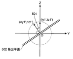
X軸角度ずれ量は、YZ平面に投影した測定法線ベクトルN’と基準法線ベクトルT’とから求められる、すなわち、図11に示すように、測定法線ベクトルN’のYZ成分を正規化してなる正規化測定法線ベクトル(ny1’,nz1’)と、基準法線ベクトルT’のYZ成分を正規化してなる正規化基準法線ベクトル(ty1’,tz1’)とによってなされる角度(角度501)として定義される。つまり、この角度501をX軸角度ずれ量ψとすると、以下の(14)式を満たすψを求めればよい。なお、図11は、X軸の正方向から見たYZ平面図であり、例えばZ軸方向を上記正規化基準法線ベクトル方向(理想方向)とした場合を示している。また、符号502は、上記正規化測定法線ベクトル(ny1’,nz1’)を有する、YZ平面と垂直な方向の平面(抽出平面という)を示している。また、(14)式はベクトル(ny1’,nz1’)と(ty1’,tz1’)との内積を示している。
cosψ=ny1’・ty1’+nz1’・tz1’ ・・・(14)
<Calculation of X-axis angle deviation>
The X-axis angle deviation amount is obtained from the measurement normal vector N ′ projected on the YZ plane and the reference normal vector T ′. That is, as shown in FIG. 11, the YZ component of the measurement normal vector N ′ is normalized. The angle formed by the normalized measurement normal vector (ny1 ′, nz1 ′) obtained by normalizing and the normalized reference normal vector (ty1 ′, tz1 ′) obtained by normalizing the YZ component of the reference normal vector T ′. (Angle 501). That is, if this
cos ψ = ny1 ′ · ty1 ′ + nz1 ′ · tz1 ′ (14)
<Y軸角度ずれ量の算出>
Y軸角度ずれ量も同様に、測定法線ベクトルN’と基準法線ベクトルT’とをZX平面に投影し、この測定法線ベクトルN’のZX成分を正規化してなる正規化測定法線ベクトル(nx2’,nz2’)と、基準法線ベクトルT’のZX成分を正規化してなる正規化基準法線ベクトル(tx2’,tz2’)との角度として定義したY軸角度ずれ量を、以下の(15)式を満たすθとして求める。
cosθ=nz2’・tz2’+nx2’・tx2’ ・・・(15)
<Calculation of Y-axis angle deviation>
Similarly, the Y-axis angle deviation amount is also a normalized measurement normal obtained by projecting the measurement normal vector N ′ and the reference normal vector T ′ onto the ZX plane and normalizing the ZX component of the measurement normal vector N ′. Y axis angle deviation amount defined as an angle between the vector (nx2 ′, nz2 ′) and the normalized reference normal vector (tx2 ′, tz2 ′) obtained by normalizing the ZX component of the reference normal vector T ′, It calculates | requires as (theta) which satisfy | fills the following (15) Formula.
cos θ = nz2 ′ · tz2 ′ + nx2 ′ · tx2 ′ (15)
<Z軸角度ずれ量の算出>
Z軸角度ずれ量も同様に、測定方向ベクトルR’と基準方向ベクトルS’とをXY平面に投影し、この測定方向ベクトルR’のXY成分を正規化してなる正規化測定方向ベクトル(rx3’,ry3’)と、基準方向ベクトルS’のXY成分を正規化してなる正規化基準法線ベクトル(sx3’,sy3’)との角度として定義したZ軸角度ずれ量を、以下の(16)式を満たすφとして求める。
cosφ=dx3’・sx3’+dy3’・sy3’ ・・・(16)
<Calculation of Z-axis angle deviation>
Similarly, the Z-axis angle deviation amount is also obtained by projecting the measurement direction vector R ′ and the reference direction vector S ′ onto the XY plane and normalizing the XY component of the measurement direction vector R ′ (rx3 ′). , Ry3 ′) and the Z-axis angle deviation defined as an angle between the normalized reference normal vector (sx3 ′, sy3 ′) obtained by normalizing the XY component of the reference direction vector S ′, Obtained as φ satisfying the equation.
cosφ = dx3 ′ · sx3 ′ + dy3 ′ · sy3 ′ (16)
このようにして調整パラメータ算出部45によってX軸角度ずれ量ψ、Y軸角度ずれ量θ及びZ軸角度ずれ量φが算出される。校正装置3すなわち位置角度調整機構32は、これら角度ずれ量ψ、θ及びφの情報と、上記調整パラメータ算出部45により求めたXYZ位置ずれベクトルK’との情報に基づいて、角度ずれを修正(調整)するべく各X、Z、Y軸回転部322〜324を駆動させるとともに、位置ずれ(XYZ位置ずれ)を修正するべく各Y、X、Z軸移動部325〜327を駆動させることで、測定装置2に対する校正チャート31の位置合わせを行う。ところで、これら位置・角度ずれ量は、測定装置座標系での位置、角度ずれ量がワールド座標系に変換されたものとしてのずれ量であるため、位置角度調整機構32による実際の駆動では、上記求められた角度ずれ量ψ、θ及びφによる駆動方向と逆の方向に駆動させることになる。
In this way, the adjustment
上記位置・角度ずれを修正する前の座標をP’(x’,y’,z’)、位置・角度ずれを修正した後の座標をP”(x”,y”,z”)とすると、Y軸中心に−(マイナス)θ回転、Z軸中心に−φ回転、X軸中心に−ψ回転して、さらに−K’だけ平行移動(この平行移動を変換行列Lで定義する)するように、すなわち以下の(17)式に示す変換が行われるように、s以下の(18)式に示す変換行列Mの情報を用いて位置角度調整機構32を駆動させる。これにより当該校正チャート31の位置合わせを行うことができる。調整パラメータ算出部45は、この変換行列Mを調整パラメータとして算出する。
P”=M・P’ ・・・(17)
M=Y−θ・Z−φ・X−ψ・L ・・・(18)
If the coordinates before correcting the position / angle deviation are P ′ (x ′, y ′, z ′) and the coordinates after the position / angle deviation are corrected are P ″ (x ″, y ″, z ″). Rotate − (minus) θ around the Y axis, rotate −φ around the Z axis, rotate −ψ around the X axis, and further translate by −K ′ (this translation is defined by the transformation matrix L). In other words, the position
P ″ = M · P ′ (17)
M = Y −θ · Z −φ · X −ψ · L (18)
調整パラメータ送信部46は、調整パラメータ算出部45により算出された調整パラメータ(変換行列M)を位置角度調整機構32の各駆動部へ送信するものである。
The adjustment
位置角度調整機構32は、調整パラメータ送信部46から送信されてきた(情報処理装置4から指示された)調整パラメータ分だけ自動的に駆動する。当該位置角度調整機構32による調整パラメータに基づく位置合わせに関する駆動のことを適宜「調整駆動」という。この調整駆動動作は、例えば図10において、校正チャート31の位置が測定装置座標系で例えば+Y方向にずれていると測定装置2により測定されると、この測定結果から求めた調整パラメータに基づいて、このずれを修正するべく位置角度調整機構32により校正チャート31を校正装置座標系で例えば+Z方向及び−Y方向に、つまり+Z方向ベクトルと−Y方向ベクトルとの合成ベクトル方向に移動させる動作であると言える。
The position
基準情報記憶部47は、校正チャート31の位置合わせにおける基準(理想、目標)となる位置及び角度に関する情報(基準情報という)を既定値として記憶しておくものである。この基準情報は、具体的には上記位置ずれにおける基準座標、角度ずれにおける基準法線ベクトルT及び基準方向ベクトルSの情報である。なお、基準情報記憶部47は、校正チャート31の実際の寸法・形状情報(真値、設計値)、例えば図3では頂面314や側面315〜318の各辺の長さ等の情報も記憶している。ただし、この寸法・形状情報は、本実施形態での“位置合わせ”が完了した後、別途、校正動作を行う際の比較用として使用される。すなわち、位置合わせ後の校正チャート31を3次元測定して得た現在の寸法・形状情報と校正チャート31の本来あるべき寸法・形状情報とが比較される。本実施形態は、この校正の前段階としての“位置合わせ”に関するものである。
The reference
エラー報知部48は、位置合わせに関する3次元測定システム1各部、具体的には例えば上記測定装置2、位置角度調整機構32(校正装置3)、ずれベクトル算出部43、調整パラメータ算出部45、姿勢検出情報受信部44の少なくとも1つの機能部について動作のエラー(異常)を検出する或いは異常の有無を判別するとともに、エラーを検出した場合には、当該エラー情報を報知するものである。
The
エラー報知部48は、例えば測定装置2による校正チャート31の測定が失敗するなどして校正チャート31の一部又は全域のデータが取得できなかった(上記各ベクトルの算出が行えなかった)ことを測定装置2から検出した場合に、当該エラーの旨を表示や音声によって出力させる。さらに具体的には、この場合、エラー報知部48は、例えば測定指示部41により測定装置2へ測定指示が行われてからの時間計測つまりタイムカウントを行い、所定時間が経過しても測定データが送信されてこない場合をエラーであると検出(判別)し、当該エラーのメッセージや警告音を情報処理装置4或いは測定装置2のモニタ(液晶画面)やスピーカから出力させる。
The
また例えば、測定装置2による3次元計測やこの3次元測定データに基づく位置、角度ずれ量などの算出は適正に行われたものの、例えばこの算出された値が位置角度調整機構32の実際の可動範囲を超過していることが判定(検出)され、このため調整駆動を行うことができないという場合などにも、同様にしてエラー報知部48によりエラー報知がなされる。なお、各機能部においてエラーが生じたことを検出する方法やエラー情報を報知する方法はこれらに限らず任意なものが採用可能である。
Further, for example, although the three-dimensional measurement by the measuring device 2 and the calculation of the position and the angle deviation amount based on the three-dimensional measurement data are appropriately performed, for example, the calculated value is the actual movable of the position
このような構成の3次元測定システム1において、校正チャート31を測定するときは、例えば上記モニタの画像で(例えばモニタ画像を見ながら)おおよその位置や姿勢を合わせてから、測定装置2による測定を行うとよい。これは、3次元測定データを用いた位置合わせを精度良く(確実に)且つより高速に行うためには、校正チャート31全領域の3次元測定データを取得することが好ましいからである。
In the three-
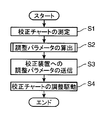
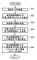
図12は、3次元測定システム1による位置合わせに関する全体的な動作の一例について説明するフローチャートである。先ず測定指示部41の指示等に応じて測定装置2により校正チャート31の測定が行われて3次元測定データが取得される(ステップS1)。次にこの測定装置2により得られた3次元測定データ(校正チャート31の形状情報)に基づいて、情報処理装置4により調整パラメータが算出される(ステップS2)。そして、算出された調整パラメータが校正装置3へ送信され(ステップS3)、この調整パラメータに基づいて、校正装置3の位置角度調整機構32により校正チャート31の調整駆動が行われる(ステップS4)。
FIG. 12 is a flowchart illustrating an example of the overall operation related to alignment by the three-
図13は、上記図12のステップS2における調整パラメータ算出の詳細な動作の一例について説明するフローチャートである。ステップS2では先ず測定装置2から送信されてきた3次元測定データが情報処理装置4の測定情報受信部42によって受信される(ステップS21)。受信されたこの3次元測定データと、基準情報記憶部47に記憶された基準情報とに基づいて、ずれベクトル算出部43によって測定装置座標系での位置ずれベクトル及び角度ずれベクトル(XY軸角度ずれベクトル、Z軸角度ずれベクトル)が算出(設定)される(ステップS22)。次に位置角度調整機構32の姿勢検出センサにより検出された校正チャート31の姿勢検出情報が姿勢検出情報受信部44により受信される(ステップS23)。受信されたこの姿勢検出情報に基づいて、調整パラメータ算出部45により上記測定装置座標系での位置ずれベクトル及び角度ずれベクトルが校正装置座標系(ワールド座標系)に変換される(ステップS24)。そして、この変換された角度ずれベクトルからX軸、Y軸及びZ軸角度ずれ量(ψ、θ及びφ)が算出されて(ステップS25)、この校正装置座標系でのX軸、Y軸及びZ軸角度ずれ量と、上記変換された校正装置座標系での位置ずれベクトルとの情報に基づいて、調整パラメータとしての変換行列Mが算出される(ステップS26)。
FIG. 13 is a flowchart for explaining an example of a detailed operation of calculating the adjustment parameter in step S2 of FIG. In step S2, the three-dimensional measurement data transmitted from the measuring device 2 is first received by the measurement
以上のように本実施形態における3次元測定システム1(位置合わせシステム)によれば、測定装置2(測定手段)によって、立体的な測定対象物である立体測定物(校正チャート31或いは校正チャート700)が非接触に3次元測定されて該立体測定物の3次元データが取得される。また、基準情報記憶部47(記憶手段)によって、測定手段と立体測定物との位置合わせの基準となる基準情報(本実施形態では、基準座標、基準法線ベクトルT及び基準方向ベクトルS等の情報)が予め記憶される。また、ずれベクトル算出部43(ズレ量算出手段)によって、3次元データと基準情報とに基づいて測定手段の座標系における当該測定手段と立体測定物との相互の位置ずれ量及び角度ずれ量が算出される。そして、調整パラメータ算出部45(変換手段)によって、位置ずれ量及び角度ずれ量が位置合わせにおける調整動作用の調整パラメータに変換され、位置角度調整機構32(調整手段)によって、調整パラメータに基づいて立体測定物の位置及び角度が調整される。
As described above, according to the three-dimensional measurement system 1 (positioning system) in this embodiment, the measurement device 2 (measurement unit) uses the three-dimensional measurement object (the
このように測定手段と立体測定物との位置合わせが、調整手段による立体測定物の位置及び角度の調整により行われるので、すなわち当該位置合わせが、測定手段を動かさずに、立体測定物を動かすことによって行われるので、広いスペース(設置スペース或いは移動スペース)を必要とすることなく位置合わせすることができる。また、3次元データと基準情報とに基づいて測定手段と立体測定物との相互の位置ずれ量及び角度ずれ量が自動的に算出されるので、ユーザが基準となる位置を指示する動作が必要がなく、容易に位置合わせすることができる。位置ずれ量及び角度ずれ量が調整手段の調整パラメータに変換されることからも、この調整パラメータを用いて、当該位置合わせのための調整作業が例えば自動駆動、手動操作いずれで行う場合にも容易に行えるようになる。また、測定手段を動かさずに(位置や向きを変えることなく)、実際に測定するのと同じ姿勢を保った状態で当該位置合わせが行われるため、姿勢差の発生を防止することができ、ひいては高精度な位置合わせが可能となる。測定手段による立体測定物の3次元測定により3次元データが取得される、すなわち調整手段による調整動作において立体測定物の3次元データが用いられることからも(2次元データを用いた位置合わせを行う場合と比べて)、高精度な位置合わせが可能となる。 As described above, the positioning of the measuring means and the three-dimensional measuring object is performed by adjusting the position and angle of the three-dimensional measuring object by the adjusting means. That is, the positioning moves the three-dimensional measuring object without moving the measuring means. Therefore, alignment can be performed without requiring a wide space (installation space or movement space). Also, since the mutual displacement amount and angular displacement amount between the measuring means and the three-dimensional object are automatically calculated based on the three-dimensional data and the reference information, the user needs to indicate the reference position. And can be easily aligned. Since the positional deviation amount and the angular deviation amount are converted into the adjustment parameters of the adjustment means, it is easy to use this adjustment parameter when the adjustment work for the alignment is performed by, for example, automatic driving or manual operation. Will be able to do. In addition, since the positioning is performed while maintaining the same posture as that actually measured without moving the measuring means (without changing the position or orientation), it is possible to prevent the occurrence of a posture difference, As a result, highly accurate alignment is possible. The three-dimensional data is acquired by the three-dimensional measurement of the three-dimensional object by the measuring means, that is, the three-dimensional data of the three-dimensional object is used in the adjustment operation by the adjusting means (alignment using two-dimensional data is performed). Compared to the case), highly accurate alignment is possible.
また、X、Y及びZ軸回転部322〜324(位置角度調整機構32;姿勢検出手段)によって、立体測定物の姿勢が検出される。そして、変換手段によって、姿勢検出手段による姿勢検出情報を用いて測定手段の座標系と調整手段の座標系との関係を示す関係式(座標変換式;例えば座標変換行列M)が算出され、該関係式に基づく座標変換が行われることによって、測定手段の座標系における位置ずれ量及び角度ずれ量が、調整手段の座標系における調整パラメータに変換されるので、測定手段側で求めた位置ずれ量及び角度ずれ量を、調整手段側での位置ずれ量及び角度ずれ量として扱うことができるようになる。これにより、測定手段を動かすことなく立体測定物の方を動かして当該位置合わせする構成を実現することができ、ひいては広いスペース(設置又は移動スペース)を必要とせず、容易且つ高精度に位置合わせすることが可能となる。
Further, the posture of the three-dimensional object is detected by the X, Y, and Z
また、立体測定物が、測定手段の校正を行うための、形状が既知である基準立体物(構成チャート31或いは700)とされる。そして、調整手段によって、校正を行う前段階としての位置合わせを行うべく基準立体物の位置及び角度が調整されるので、位置合わせシステムを、基準立体物を用いて測定手段の校正を行う校正システムとして使用することができる、すなわち3次元測定システム1を位置合わせシステムとすることができる。
The three-dimensional object is a reference three-dimensional object (
また、調整手段が備える自動調整機構によって、調整を行うべく調整パラメータに基づいて自動的に駆動が行われるので、調整手段による調整動作を自動調整機構によって自動的に行うことができ、測定手段と立体測定物との位置合わせが一層容易に行えるようになる。 In addition, since the automatic adjustment mechanism provided in the adjustment unit automatically drives based on the adjustment parameter to perform the adjustment, the adjustment operation by the adjustment unit can be automatically performed by the automatic adjustment mechanism. Positioning with a three-dimensional object can be performed more easily.
また、調整パラメータ算出部45(或いはモニタやスピーカ;調整情報報知手段)によって、調整パラメータに関する情報がユーザに報知される。そして、調整手段が備える手動調整機構(例えば上述の治具)によって、調整を行うべくユーザの手動操作による駆動が行われるので、調整手段による調整動作をユーザによる手動調整機構を用いた手動操作によって行うことができ、ひいては測定手段と立体測定物との位置合わせ動作における自由度が高くなる。 Further, the adjustment parameter calculation unit 45 (or monitor or speaker; adjustment information notification means) notifies the user of information regarding the adjustment parameters. Then, the manual adjustment mechanism (for example, the above-described jig) provided in the adjustment means is driven by the user's manual operation to perform the adjustment. Therefore, the adjustment operation by the adjustment means is performed manually by the user using the manual adjustment mechanism. As a result, the degree of freedom in the alignment operation between the measuring means and the three-dimensional object increases.
また、基準立体物(校正チャート31)が角錐台状のものとされるので、角錐台状の簡易な形状の基準立体物を用いて、容易に且つ精度良く位置ずれ量及び角度ずれ量を求めて当該位置合わせを行うことができるとともに、この基準立体物を用いて、位置合わせ後の校正を容易に且つ精度良く行うことができる。 Further, since the reference three-dimensional object (calibration chart 31) is in the shape of a truncated pyramid, the amount of positional deviation and the amount of angular deviation can be obtained easily and accurately using a reference three-dimensional object having a simple shape of a truncated pyramid. Thus, the alignment can be performed, and the calibration after the alignment can be easily and accurately performed using the reference three-dimensional object.
また、エラー報知部48(異常検出手段)によって、測定手段、ズレ量算出手段、変換手段、調整手段及び姿勢検出手段の少なくとも1つの手段について動作の異常が検出される。そして、エラー報知部48(異常報知手段)によって、異常検出手段により異常が検出された場合に、該異常を示す情報(異常情報)がユーザに報知されるので、位置合わせシステムの動作(位置合わせの動作)に異常が発生していることをユーザが容易に知ることができる。 Further, the error notification unit 48 (abnormality detection means) detects an abnormality in the operation of at least one of the measurement means, the deviation amount calculation means, the conversion means, the adjustment means, and the attitude detection means. Then, when an abnormality is detected by the error detection unit by the error notification unit 48 (abnormality notification unit), information indicating the abnormality (abnormality information) is notified to the user. The user can easily know that an abnormality has occurred in the operation).
また、位置合わせシステムが、測定手段である測定装置2と、立体測定物(校正チャート31或いは700)と、該立体測定物の位置及び角度を変化させることが可能に支持する調整手段(位置角度調整機構32)とからなる被測定装置(校正装置3)と、記憶手段、ズレ量算出手段及び変換手段を内蔵するとともに、測定装置及び被測定装置それぞれと通信可能に接続された情報処理装置4とからなるものとされるので、位置合わせシステムを、測定装置2、校正装置3及び情報処理装置4からなるシンプルな構成のシステムとすることができる。
Further, the alignment system supports the measuring device 2 as a measuring means, the three-dimensional object (
また、本実施形態における位置合わせ方法によれば、第1の工程において、立体的な測定対象物である立体測定物が非接触に3次元測定されて該立体測定物の3次元データが取得される。第2の工程において、立体測定物を測定する測定手段と該立体測定物との位置合わせの基準となる基準情報が予め取得される。また、第3の工程において、3次元データと基準情報とに基づいて、測定手段の座標系における当該測定手段と立体測定物との相互の位置ずれ量及び角度ずれ量が算出される。そして、第4の工程において、位置ずれ量及び角度ずれ量が位置合わせにおける調整動作用の調整パラメータに変換され、第5の工程において、調整パラメータに基づいて、立体測定物の位置及び角度が調整される。 Further, according to the alignment method in the present embodiment, in the first step, the three-dimensional measurement object that is a three-dimensional measurement object is three-dimensionally measured in a non-contact manner, and three-dimensional data of the three-dimensional measurement object is acquired. The In the second step, reference information serving as a reference for alignment between the measuring means for measuring the three-dimensional object and the three-dimensional object is acquired in advance. In the third step, based on the three-dimensional data and the reference information, the mutual positional deviation amount and angular deviation amount between the measuring means and the three-dimensional measuring object in the coordinate system of the measuring means are calculated. Then, in the fourth step, the positional deviation amount and the angular deviation amount are converted into adjustment parameters for adjustment operation in alignment, and in the fifth step, the position and angle of the three-dimensional measurement object are adjusted based on the adjustment parameters. Is done.
このように、測定手段と立体測定物との位置合わせが、立体測定物の位置及び角度の調整により行われるので、すなわち当該位置合わせが、測定手段を動かさずに、立体測定物を動かすことによって行われるので、広いスペース(設置スペース或いは移動スペース)を必要とすることなく位置合わせすることができる。また、3次元データと基準情報とに基づいて測定手段と立体測定物との相互の位置ずれ量及び角度ずれ量が自動的に算出されるので、ユーザが基準となる位置を指示する動作が必要がなく、容易に位置合わせすることができる。位置ずれ量及び角度ずれ量が調整動作用の調整パラメータに変換されることからも、この調整パラメータを用いて、当該位置合わせのための調整作業が例えば自動駆動、手動操作いずれで行う場合にも容易に行えるようになる。また、測定手段を動かさずに(位置や向きを変えることなく)、実際に測定するのと同じ姿勢を保った状態で当該位置合わせが行われるため、姿勢差の発生を防止することができ、ひいては高精度な位置合わせが可能となる。測定手段による立体測定物の3次元測定により3次元データが取得される、すなわち立体測定物の位置及び角度の調整動作において立体測定物の3次元データが用いられることからも(2次元データを用いた位置合わせを行う場合と比べて)、高精度な位置合わせが可能となる。 As described above, the alignment between the measuring means and the three-dimensional object is performed by adjusting the position and angle of the three-dimensional object, that is, the alignment is performed by moving the three-dimensional object without moving the measuring means. Since it is performed, alignment can be performed without requiring a large space (installation space or movement space). Also, since the mutual displacement amount and angular displacement amount between the measuring means and the three-dimensional object are automatically calculated based on the three-dimensional data and the reference information, the user needs to indicate the reference position. And can be easily aligned. Since the positional deviation amount and the angular deviation amount are converted into the adjustment parameters for the adjustment operation, this adjustment parameter is used to perform the adjustment work for the alignment by either automatic driving or manual operation, for example. It becomes easy to do. In addition, since the positioning is performed while maintaining the same posture as that actually measured without moving the measuring means (without changing the position or orientation), it is possible to prevent the occurrence of a posture difference, As a result, highly accurate alignment is possible. The three-dimensional data is acquired by the three-dimensional measurement of the three-dimensional object by the measuring means, that is, the three-dimensional data of the three-dimensional object is used in the adjustment operation of the position and angle of the three-dimensional object (using the two-dimensional data). Compared with the case where the alignment is performed), highly accurate alignment is possible.
また、上記位置合わせ方法が、第6の工程において、立体測定物の姿勢が検出され、上記第4の工程において、当該第6の工程において検出された姿勢検出情報を用いて測定手段の座標系と、調整を行う調整手段の座標系との関係を示す関係式が算出され、該関係式に基づく座標変換が行われることによって、測定手段の座標系における位置ずれ量及び角度ずれ量が、調整手段の座標系における調整パラメータに変換される方法とされるので、測定手段側で求めた位置ずれ量及び角度ずれ量を、調整手段側での位置ずれ量及び角度ずれ量として扱うことができるようになる。これにより、測定手段を動かすことなく立体測定物の方を動かして当該位置合わせする構成を実現することができ、ひいては広いスペースを必要とせず、容易且つ高精度に位置合わせすることが可能となる。 In the positioning method, the orientation of the three-dimensional object is detected in the sixth step, and the coordinate system of the measuring unit is used in the fourth step using the orientation detection information detected in the sixth step. And a relational expression showing the relationship between the coordinate system of the adjusting means for adjusting and the coordinate conversion based on the relational expression is performed, whereby the positional deviation amount and the angular deviation amount in the coordinate system of the measuring means are adjusted. Since the method is converted into the adjustment parameter in the coordinate system of the means, the positional deviation amount and the angular deviation amount obtained on the measuring means side can be handled as the positional deviation amount and the angular deviation amount on the adjustment means side. become. As a result, it is possible to realize a configuration in which the three-dimensional object is moved and moved without moving the measuring means, and therefore, it is possible to align easily and with high accuracy without requiring a wide space. .
なお、本発明は、以下の態様をとることができる。
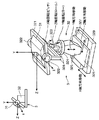
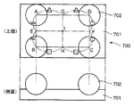
(A)校正チャートは図3に示す形状のものでなく、例えば図14に示すように複数の球体を備えてなる校正チャート700であってもよい。この校正チャート700は、例えば長方形の平板体701の一平面側(上面側)に複数ここでは4つの同じ球体702が配設されている。各球体702は下部が平板体701に没入した状態で固定されており、これら球体702の中心点により上面視で四角形ABCD(校正チャート31の四角形ABCDに相当)が構成されている。
In addition, this invention can take the following aspects.
(A) The calibration chart is not the one shown in FIG. 3, but may be a
このように、校正チャート(基準立体物)が所定の位置関係で(ここでは平板体の一平面側に位置する位置関係で)配設された複数の球体からなる校正チャート700とされるので、所定の位置関係で配設された複数の球体からなる簡易な形状の基準立体物を用いて、容易に且つ精度良く位置ずれ量及び角度ずれ量を求めて当該位置合わせを行うことができるとともに、この基準立体物を用いて、位置合わせ後の校正を容易に且つ精度良く行うことができる。ただし、複数の球体が互いに所定の位置関係となるように固定して設置できるすなわち支持可能なものであれば、必ずしも平板体に配設されたものでなくともよく、当該球体を支持する支持部の形状は任意なものが採用可能である。なお、校正チャートはこれら(校正チャート31、700)のようなものに限定されず、要は形状が既知の立体測定物であれば何れのものでも構わない。
Thus, since the calibration chart (reference solid object) is a
(B)3次元測定システム1は、測定装置2と校正チャート31との位置ずれ量、角度ずれ量がある一定範囲内に収束するまで上記位置合わせ動作(図12のステップS1からステップS4までの動作)を繰り返し行う構成であってもよい。この場合、主制御部40に例えば収束判定部を備えておき、第1回目の位置合わせ動作(位置角度調整機構32による調整駆動)が終了した後、自動的に測定装置2に校正チャート31を測定させる。そして、この測定により得られた位置ずれ量、角度ずれ量(例えば図13のステップS22における位置、角度ずれベクトル量)が所定の閾値よりも小さい値であるか否かを収束判定部により判定し、“否”と判定された場合には引き続いて(ステップS22以降の)位置合わせ動作を実行させる。
(B) The three-
(C)校正チャート31の姿勢(角度絶対値)を検出する方法は上述に限らず任意な方法でよい。例えば位置角度調整機構32の冶具(ネジやつまみ)等に分度器等を取り付けておき、ユーザがこの目盛りを目で読み取るような方法であってもよい。また、本実施形態では、校正チャート31の姿勢検出はこのように校正装置3(位置角度調整機構32)にて行うようにしているが、これに限らず、校正チャート31の姿勢検出を測定装置2側で行う、すなわち測定装置2によって校正チャート31の回転角度(傾斜角度、角度絶対値)を測定するようにしてもよい。この場合、例えば測定装置2のスタンド23に角度の目盛りを取り付けておき、その目盛り値を読み取るようにしてもよい。また、当該姿勢検出は、加速度センサなどの姿勢センサを測定装置2や校正チャート31に取り付けることでも実現できる。
(C) The method for detecting the posture (absolute angle value) of the
(D)上記実施形態では、校正チャート31の位置・角度を調整するものとして、位置角度調整機構32のように、情報処理装置4(PC)からの指示に基づいて自動的に調整駆動するものを採用しているが、これに限らず、情報処理装置4のモニタ(アプリケーション上)等に上述で求めた調整パラメータに関する調整情報を、例えば治具の回転目盛り量といった調整量(駆動量)の情報でモニタ等に表示し、この表示された調整量を参照しつつユーザ自身が位置角度調整機構32を手動(マニュアル)で操作して調整駆動を行うようにしてもよい。ただし、この治具が当該ユーザによる手動での調整を行う手動調整機構に該当する。なお、この場合、調整パラメータ算出部45によって、上記調整量をユーザに報知するべくこの調整量情報のモニタ等への表示制御が行われる構成でもよい。
(D) In the above embodiment, the position / angle of the
(E)上記実施形態では、測定装置2による測定データに基づく調整パラメータの算出等の演算を、測定装置2とは別に設けた情報処理装置4にて行っているが、この演算を測定装置2にて行うすなわち測定装置2に演算部が内蔵されていてもよい。この場合は情報処理装置4が不要であり、測定装置2と位置角度調整機構32とが直接、通信ケーブル等で接続されることになる。
(E) In the above embodiment, the calculation of the adjustment parameter based on the measurement data by the measurement apparatus 2 is performed by the information processing apparatus 4 provided separately from the measurement apparatus 2. That is, the calculation unit may be built in the measuring apparatus 2. In this case, the information processing device 4 is unnecessary, and the measuring device 2 and the position
(F)上記実施形態は、測定装置2と校正チャート31との位置合わせについて記載しているが、必ずしも校正チャートでなくてもよく、測定装置2と形状が既知の測定物との位置合わせにおいても適用可能である。すなわち“校正”を行うシステム(3次元測定システム)での位置合わせでなくともよく、要は測定に際して相対する2者間の位置合わせを行うものであれば、3次元測定システムでなく例えば精度検証システム(測定対象物が所要の形状精度を有しているか否かを検証するシステム)であってもよい。
(F) The above embodiment describes the alignment between the measuring device 2 and the
1 3次元測定システム(位置合わせシステム)
2 測定装置(測定手段)
23 スタンド
24、33 通信ケーブル
231 フレーム体
3 校正装置(被測定装置)
31 校正チャート(立体測定物、基準立体物)
314 頂面
32 位置角度調整機構(調整手段)
321 載置台
322 X軸回転部(姿勢検出手段)
323 Z軸回転部(姿勢検出手段)
324 Y軸回転部(姿勢検出手段)
325 Y軸移動部
326 X軸移動部
327 Z軸移動部
328 支持フレーム
329 基台
4 情報処理装置
40 主制御部
41 測定指示部
42 測定情報受信部
43 ずれベクトル算出部(ズレ量算出手段)
44 姿勢検出情報受信部(姿勢検出手段)
45 調整パラメータ算出部(変換手段、調整情報報知手段)
46 調整パラメータ送信部
47 基準情報記憶部(記憶手段)
48 エラー報知部(異常検出手段、異常報知手段)
700 校正チャート(立体測定物、基準立体物)
701 平板体
702 球体
1 3D measurement system (alignment system)
2 Measuring equipment (measuring means)
23
31 Calibration chart (stereoscopic measurement object, reference solid object)
314
321 mounting table 322 X-axis rotation unit (attitude detection means)
323 Z-axis rotation unit (attitude detection means)
324 Y-axis rotation unit (attitude detection means)
325 Y-
44 posture detection information receiver (posture detection means)
45 Adjustment parameter calculation unit (conversion means, adjustment information notification means)
46 Adjustment
48 Error notification section (abnormality detection means, abnormality notification means)
700 Calibration chart (stereoscopic measurement object, reference solid object)
701
Claims (11)
前記立体測定物を非接触に3次元測定して該立体測定物の3次元データを取得する測定手段と、
前記測定手段と前記立体測定物との位置合わせの基準となる基準情報を予め記憶する記憶手段と、
前記3次元データと前記基準情報とに基づいて、前記測定手段の座標系における当該測定手段と立体測定物との相互の位置ずれ量及び角度ずれ量を算出するズレ量算出手段と、
前記位置ずれ量及び角度ずれ量を前記位置合わせにおける調整動作用の調整パラメータに変換する変換手段と、
前記調整パラメータに基づいて、前記立体測定物の位置及び角度を調整する調整手段とを備えることを特徴とする位置合わせシステム。 A three-dimensional measuring object which is a three-dimensional measuring object;
Measuring means for three-dimensionally measuring the three-dimensional object without contact to obtain three-dimensional data of the three-dimensional object;
Storage means for preliminarily storing reference information serving as a reference for alignment between the measuring means and the three-dimensional object;
Based on the three-dimensional data and the reference information, a deviation amount calculating means for calculating a mutual positional deviation amount and an angular deviation amount between the measuring means and the three-dimensional measuring object in the coordinate system of the measuring means;
Conversion means for converting the positional deviation amount and the angular deviation amount into adjustment parameters for an adjustment operation in the alignment;
An alignment system comprising adjusting means for adjusting the position and angle of the three-dimensional object based on the adjustment parameter.
前記変換手段は、
前記姿勢検出手段による姿勢検出情報を用いて前記測定手段の座標系と前記調整手段の座標系との関係を示す関係式を算出し、該関係式に基づく座標変換を行うことによって、前記測定手段の座標系における位置ずれ量及び角度ずれ量を、前記調整手段の座標系における前記調整パラメータに変換することを特徴とする請求項1に記載の位置合わせシステム。 Further comprising posture detecting means for detecting the posture of the three-dimensional measuring object,
The converting means includes
By calculating the relational expression indicating the relationship between the coordinate system of the measuring means and the coordinate system of the adjusting means using the posture detection information by the posture detecting means, and performing coordinate conversion based on the relational expression, the measuring means 2. The alignment system according to claim 1, wherein a positional deviation amount and an angular deviation amount in the coordinate system are converted into the adjustment parameters in the coordinate system of the adjustment means.
前記調整手段は、前記校正を行う前段階としての前記位置合わせを行うべく前記基準立体物の位置及び角度を調整することを特徴とする請求項1又は2に記載の位置合わせシステム。 The three-dimensional object is a reference three-dimensional object whose shape is known for calibrating the measuring means,
The alignment system according to claim 1, wherein the adjustment unit adjusts a position and an angle of the reference three-dimensional object so as to perform the alignment as a step before performing the calibration.
前記調整手段は、前記調整を行うべく前記ユーザの手動操作によって駆動する手動調整機構を備えることを特徴とする請求項1〜3のいずれかに記載の位置合わせシステム。 Adjustment information notifying means for notifying the user of information on the adjustment parameter;
The alignment system according to claim 1, wherein the adjustment unit includes a manual adjustment mechanism that is driven by a manual operation of the user to perform the adjustment.
前記異常検出手段により異常が検出された場合に、該異常を示す情報をユーザに報知する異常報知手段とをさらに備えることを特徴とする請求項2〜7のいずれかに記載の位置合わせシステム。 An abnormality detecting means for detecting an abnormality in operation of at least one of the measuring means, the deviation amount calculating means, the converting means, the adjusting means, and the posture detecting means;
The alignment system according to any one of claims 2 to 7, further comprising abnormality notifying means for notifying a user of information indicating the abnormality when an abnormality is detected by the abnormality detecting means.
前記測定手段である測定装置と、
前記立体測定物と、該立体測定物の位置及び角度を変化させることが可能に支持する前記調整手段とからなる被測定装置と、
前記記憶手段、ズレ量算出手段及び変換手段を内蔵するとともに、前記測定装置及び被測定装置それぞれと通信可能に接続された情報処理装置とからなるものであることを特徴とする請求項1〜8のいずれかに記載の位置合わせシステム。 The alignment system includes:
A measuring device as the measuring means;
A device under measurement comprising the three-dimensional object and the adjusting means that supports the position and angle of the three-dimensional object to be changed; and
9. The information processing apparatus including the storage unit, the deviation amount calculation unit, and the conversion unit, and an information processing apparatus that is communicably connected to each of the measurement apparatus and the device under measurement. The alignment system according to any one of the above.
前記立体測定物を測定する測定手段と該立体測定物との位置合わせの基準となる基準情報を予め取得する第2の工程と、
前記3次元データと前記基準情報とに基づいて、前記測定手段の座標系における当該測定手段と立体測定物との相互の位置ずれ量及び角度ずれ量を算出する第3の工程と、
前記位置ずれ量及び角度ずれ量を前記位置合わせにおける調整動作用の調整パラメータに変換する第4の工程と、
前記調整パラメータに基づいて、前記立体測定物の位置及び角度を調整する第5の工程とを有することを特徴とする位置合わせ方法。 A first step of three-dimensionally measuring a three-dimensional measurement object that is a three-dimensional measurement object in a non-contact manner to obtain three-dimensional data of the three-dimensional measurement object;
A second step of previously obtaining reference information that serves as a reference for alignment between the measuring means for measuring the three-dimensional object and the three-dimensional object;
A third step of calculating a mutual positional deviation amount and an angular deviation amount between the measuring means and the three-dimensional measuring object in the coordinate system of the measuring means based on the three-dimensional data and the reference information;
A fourth step of converting the positional deviation amount and the angular deviation amount into adjustment parameters for an adjustment operation in the alignment;
And a fifth step of adjusting the position and angle of the three-dimensional object based on the adjustment parameter.
前記第4の工程は、
前記第6の工程において検出された姿勢検出情報を用いて前記測定手段の座標系と、前記調整を行う調整手段の座標系との関係を示す関係式を算出し、該関係式に基づく座標変換を行うことによって、前記測定手段の座標系における位置ずれ量及び角度ずれ量を、前記調整手段の座標系における前記調整パラメータに変換する工程であることを特徴とする請求項10に記載の位置合わせ方法。 A sixth step of detecting a posture of the three-dimensional object to be measured;
The fourth step includes
Using the posture detection information detected in the sixth step, a relational expression indicating a relation between the coordinate system of the measuring means and the coordinate system of the adjusting means for performing the adjustment is calculated, and coordinate conversion based on the relational expression is performed. The position adjustment according to claim 10, wherein the positional deviation amount and the angular deviation amount in the coordinate system of the measurement unit are converted into the adjustment parameters in the coordinate system of the adjustment unit by performing Method.
Priority Applications (2)
| Application Number | Priority Date | Filing Date | Title |
|---|---|---|---|
| JP2006306406A JP2008122228A (en) | 2006-11-13 | 2006-11-13 | System and method for positioning |
| EP07021698A EP1923663A1 (en) | 2006-11-13 | 2007-11-08 | Measuring device, positioning system and positioning method |
Applications Claiming Priority (1)
| Application Number | Priority Date | Filing Date | Title |
|---|---|---|---|
| JP2006306406A JP2008122228A (en) | 2006-11-13 | 2006-11-13 | System and method for positioning |
Publications (1)
| Publication Number | Publication Date |
|---|---|
| JP2008122228A true JP2008122228A (en) | 2008-05-29 |
Family
ID=39267789
Family Applications (1)
| Application Number | Title | Priority Date | Filing Date |
|---|---|---|---|
| JP2006306406A Pending JP2008122228A (en) | 2006-11-13 | 2006-11-13 | System and method for positioning |
Country Status (2)
| Country | Link |
|---|---|
| EP (1) | EP1923663A1 (en) |
| JP (1) | JP2008122228A (en) |
Cited By (3)
| Publication number | Priority date | Publication date | Assignee | Title |
|---|---|---|---|---|
| JP2012112911A (en) * | 2010-11-29 | 2012-06-14 | National Institute Of Advanced Industrial & Technology | Calibration tool and dimensional measuring system having the same |
| JP2015214017A (en) * | 2014-05-07 | 2015-12-03 | コイロ ベズィッツ ゲゼルシャフト ミット ベシュレンクテル ハフツング ウント コンパニー エーデーファウ−ディーンストライストゥングス コマンデイトゲゼルシャフト | Saw machine for metal workpiece |
| JP2017026551A (en) * | 2015-07-27 | 2017-02-02 | 日産自動車株式会社 | Calibration target and calibration method |
Families Citing this family (1)
| Publication number | Priority date | Publication date | Assignee | Title |
|---|---|---|---|---|
| CN117733873B (en) * | 2024-02-19 | 2024-04-19 | 深圳市德富莱智能科技股份有限公司 | Three-dimensional automatic calibration system |
Family Cites Families (4)
| Publication number | Priority date | Publication date | Assignee | Title |
|---|---|---|---|---|
| US5579444A (en) * | 1987-08-28 | 1996-11-26 | Axiom Bildverarbeitungssysteme Gmbh | Adaptive vision-based controller |
| US5631973A (en) * | 1994-05-05 | 1997-05-20 | Sri International | Method for telemanipulation with telepresence |
| US6072898A (en) * | 1998-01-16 | 2000-06-06 | Beaty; Elwin M. | Method and apparatus for three dimensional inspection of electronic components |
| US7231081B2 (en) | 2001-12-28 | 2007-06-12 | Applied Precision, Llc | Stereoscopic three-dimensional metrology system and method |
-
2006
- 2006-11-13 JP JP2006306406A patent/JP2008122228A/en active Pending
-
2007
- 2007-11-08 EP EP07021698A patent/EP1923663A1/en not_active Withdrawn
Cited By (4)
| Publication number | Priority date | Publication date | Assignee | Title |
|---|---|---|---|---|
| JP2012112911A (en) * | 2010-11-29 | 2012-06-14 | National Institute Of Advanced Industrial & Technology | Calibration tool and dimensional measuring system having the same |
| JP2015214017A (en) * | 2014-05-07 | 2015-12-03 | コイロ ベズィッツ ゲゼルシャフト ミット ベシュレンクテル ハフツング ウント コンパニー エーデーファウ−ディーンストライストゥングス コマンデイトゲゼルシャフト | Saw machine for metal workpiece |
| US10576559B2 (en) | 2014-05-07 | 2020-03-03 | Keuro Besitz Gmbh & Co. Edv-Dienstleistungs Kg | Sawing machine for sawing metal workpieces |
| JP2017026551A (en) * | 2015-07-27 | 2017-02-02 | 日産自動車株式会社 | Calibration target and calibration method |
Also Published As
| Publication number | Publication date |
|---|---|
| EP1923663A1 (en) | 2008-05-21 |
Similar Documents
| Publication | Publication Date | Title |
|---|---|---|
| US20210114221A1 (en) | Method of teaching robot and robot system | |
| US11254008B2 (en) | Method and device of controlling robot system | |
| EP3619498B1 (en) | Triangulation scanner having flat geometry and projecting uncoded spots | |
| CN103383238B (en) | Image measuring apparatus, image measuring method and image measurement program | |
| JP5670416B2 (en) | Robot system display device | |
| US9645217B2 (en) | System and method for error correction for CNC machines | |
| CN107883831B (en) | Measurement system and measurement method | |
| US20150377606A1 (en) | Projection system | |
| JP2005201824A (en) | Measuring device | |
| JP7102115B2 (en) | Calibration method, calibration device, 3D measuring device, 3D visual measuring device, robot end effector, program, recording medium | |
| JP5618770B2 (en) | Robot calibration apparatus and calibration method | |
| JP2004257927A (en) | Three-dimensional profile measuring system and method for measuring the same | |
| JP6670974B1 (en) | Robot coordinate system alignment method, alignment system, and alignment device | |
| JP6736798B1 (en) | Work setting method for work device, work setting support system, and work setting support program | |
| CN114770517B (en) | Method for calibrating robot through point cloud acquisition device and calibration system | |
| JP2008122228A (en) | System and method for positioning | |
| JP2007085912A (en) | Position measurement method, position measuring device and position measuring system | |
| CN114770516A (en) | Method for calibrating robot through point cloud obtaining device and calibration system | |
| JPH07237158A (en) | Position-attitude detecting method and device thereof and flexible production system | |
| KR20160129652A (en) | Apparatus and method for manufacturing a camera module | |
| Qiao | Advanced sensing development to support robot accuracy assessment and improvement | |
| JP2017007026A (en) | Position correcting system | |
| JP2004347492A (en) | Apparatus for measuring accuracy of workpiece and method for measuring accuracy | |
| WO2023135764A1 (en) | Robot device provided with three-dimensional sensor and method for controlling robot device | |
| CN116348252A (en) | Tool deformation amount calculation device for robot, tool deformation amount calculation system for robot, and tool deformation amount calculation method for robot |