JP2007228403A - Gateway device and resource assigning method - Google Patents
Gateway device and resource assigning method Download PDFInfo
- Publication number
- JP2007228403A JP2007228403A JP2006048818A JP2006048818A JP2007228403A JP 2007228403 A JP2007228403 A JP 2007228403A JP 2006048818 A JP2006048818 A JP 2006048818A JP 2006048818 A JP2006048818 A JP 2006048818A JP 2007228403 A JP2007228403 A JP 2007228403A
- Authority
- JP
- Japan
- Prior art keywords
- resource
- group
- media gateway
- channel resources
- communication
- Prior art date
- Legal status (The legal status is an assumption and is not a legal conclusion. Google has not performed a legal analysis and makes no representation as to the accuracy of the status listed.)
- Pending
Links
Images


Classifications
-
- H—ELECTRICITY
- H04—ELECTRIC COMMUNICATION TECHNIQUE
- H04L—TRANSMISSION OF DIGITAL INFORMATION, e.g. TELEGRAPHIC COMMUNICATION
- H04L12/00—Data switching networks
- H04L12/66—Arrangements for connecting between networks having differing types of switching systems, e.g. gateways
Abstract
Description
この発明は、例えばIP(Internet Protocol)電話システム等のように、IP網を介して通信端末間で音声通信を行なうシステムに係り、これら通信端末と非IP網との間でメディアゲートウェイチャネルリソースを介して音声通信を可能とするゲートウェイ装置及びリソース割り当て方法に関する。 The present invention relates to a system for performing voice communication between communication terminals via an IP network, such as an IP (Internet Protocol) telephone system, for example, and media gateway channel resources are allocated between these communication terminals and a non-IP network. The present invention relates to a gateway device and a resource allocation method that enable voice communication via the network.
近年、IP網を介して、双方向に画像や音声をパケットデータとして、リアルタイムに送受信するネットワーク電話システム(IP電話システム)が普及し始めている。 2. Description of the Related Art In recent years, network telephone systems (IP telephone systems) that transmit and receive images and sounds as packet data in both directions via an IP network have begun to spread.
このIP電話システムでは、IP網にIP電話端末を接続するとともに、IP網をゲートウェイもしくは主装置を介してアナログ電話回線または公衆網等の回線交換網に接続し、ゲートウェイにおいてメディアゲートウェイチャネルリソースによりプロトコル変換及びデータのフォーマット変換等を行うことにより、IP電話端末と回線交換網との間で音声通信を可能にしている。 In this IP telephone system, an IP telephone terminal is connected to an IP network, and the IP network is connected to a circuit switching network such as an analog telephone line or a public network through a gateway or a main unit, and the gateway uses a protocol by a media gateway channel resource. By performing conversion and data format conversion, voice communication is enabled between the IP telephone terminal and the circuit switching network.
ところで、この種のシステムでは、ゲートウェイにおいて、例えば同一時間帯で複数のIP電話端末からメディアゲートウェイチャネルリソースの使用要求が発生した場合に、複数のIP電話端末に対し同一の条件でメディアゲートウェイチャネルリソースが割り当てられる。このため、各IP電話端末のユーザに応じたきめ細かなサービスを行うことができない。 By the way, in this type of system, in the gateway, for example, when requests for use of media gateway channel resources are generated from a plurality of IP telephone terminals in the same time zone, the media gateway channel resources are the same for the plurality of IP telephone terminals. Is assigned. For this reason, it is not possible to provide a detailed service according to the user of each IP telephone terminal.
なお、従来では、ISDN回線をLAN(Local Area Network)データ通信用と音声通信用とで共用する場合に、ISDN回線の各チャネルの使用状況に応じて、LANデータ通信用に割り当てるチャネル数及び音声通信用に割り当てるチャネル数を変更する手法が提案されている(例えば、特許文献1)。
しかしながら、上記手法は、ISDN回線を伝送する信号の種類によりチャネル割当てを変更するものであり、IP電話端末を対象としたものではない。 However, the above method changes the channel assignment according to the type of signal transmitted through the ISDN line, and is not intended for an IP telephone terminal.
そこで、この発明の目的は、メディアゲートウェイチャネルリソースを追加することなく、少数のメディアゲートウェイチャネルリソースをそれよりも多数の電話端末で共用する場合に、メディアゲートウェイチャネルリソースを効率良く割り当て得るゲートウェイ装置及びリソース割り当て方法を提供することにある。 Accordingly, an object of the present invention is to provide a gateway device capable of efficiently allocating media gateway channel resources when a small number of media gateway channel resources are shared by a larger number of telephone terminals without adding media gateway channel resources. It is to provide a resource allocation method.
この発明は、上記目的を達成するために、以下のように構成される。
複数の通信端末をパケット通信網を介して収容するとともに、パケット通信網とは異なる通信網を接続可能とし、複数の通信端末と通信網との間を複数のメディアゲートウェイチャネルリソースを介して接続して通信を可能とするゲートウェイ装置において、複数のメディアゲートウェイチャネルリソースを必要度に応じて分割して構成した複数のリソースグループを保持するプールと、これら複数のリソースグループとリソースグループに属する電話端末との対応関係を表すグループテーブルを記憶する記憶手段と、複数の通信端末のうちの任意の通信端末についてメディアゲートウェイチャネルリソースの使用要求が発生した場合に、グループテーブルを参照し、この参照結果に基づいて任意の通信端末に対し該当するリソースグループの中の空きのメディアゲートウェイチャネルリソースを割り当てる制御手段とを備えるようにしたものである。
In order to achieve the above object, the present invention is configured as follows.
A plurality of communication terminals are accommodated via a packet communication network, a communication network different from the packet communication network can be connected, and a plurality of communication terminals and a communication network are connected via a plurality of media gateway channel resources. A plurality of resource groups configured by dividing a plurality of media gateway channel resources according to necessity, a plurality of resource groups, and telephone terminals belonging to the resource groups. Storage means for storing a group table representing the correspondence relationship between the media gateway channel resource when a request for using the media gateway channel resource is generated for any communication terminal of the plurality of communication terminals, and based on the reference result Applicable resource group for any communication terminal It is obtained as a control means for assigning a media gateway channel resources free in.
この構成によれば、複数のメディアゲートウェイチャネルリソースを必要度に応じてグループ化してこのリソースグループと複数の通信端末とを対応付けることにより、通信網と通信を行なう際にプールの中から使用するメディアゲートウェイチャネルリソースを特定することができる。このため、例えば最も通信網を利用する部署及び通信網の利用回数が少ない部署が1つのシステムを共用する場合に、各部署ごとに使用するメディアゲートウェイチャネルリソース数を限定することができ、これによりメディアゲートウェイチャネルリソースを追加することなく、少数のメディアゲートウェイチャネルリソースをそれよりも多数の通信端末で共用する場合に、メディアゲートウェイチャネルリソースを効率良く割り当て、通信端末のユーザ別のきめ細かなサービスを実現できる。 According to this configuration, a plurality of media gateway channel resources are grouped according to necessity, and the resource group and a plurality of communication terminals are associated with each other, whereby media used from the pool when communicating with the communication network. Gateway channel resources can be identified. For this reason, for example, when a department that uses the communication network and a department that uses the least number of communication networks share one system, the number of media gateway channel resources used for each department can be limited. When a small number of media gateway channel resources are shared by a larger number of communication terminals without adding a media gateway channel resource, the media gateway channel resources are allocated efficiently, and detailed services are provided for each user of the communication terminal. it can.
パケット通信網が複数のセグメントに分割されるとき、記憶手段は、セグメントごとにグループテーブルを記憶することを特徴とする。
この構成によれば、複数の通信端末に対しセグメント単位でチャネルリソースの割り当てを行なうことができる。
When the packet communication network is divided into a plurality of segments, the storage means stores a group table for each segment.
According to this configuration, channel resources can be allocated to a plurality of communication terminals in units of segments.
記憶手段は、複数の通信端末のうち少なくとも1つの通信端末についてセグメント間で必要度が同一のリソースグループに属する複数のグループテーブルを記憶することを特徴とする。 The storage means stores a plurality of group tables belonging to resource groups having the same degree of necessity between segments for at least one communication terminal among the plurality of communication terminals.
この構成によれば、ある通信端末についてセグメント間で移動したとしても、移動先のセグメントで移動元のリソースグループと同一の必要度となるリソースグループに属することになり、これにより移動元と同一のサービスを継続して利用できる。 According to this configuration, even if a certain communication terminal moves between segments, it belongs to a resource group having the same degree of necessity as the source resource group in the destination segment. The service can be used continuously.
さらに、予め設定される条件に従って、プールに保持されるリソースグループごとのメディアゲートウェイチャネルリソース数を変更する変更制御手段を備えたことを特徴とする。なお、条件の判断に、時間帯、メディアゲートウェイチャネルリソースの使用頻度、使用したメディアゲートウェイチャネルリソースを捕捉元のリソースグループに戻す際の当該リソースグループ内のメディアゲートウェイチャネルリソースの空き状態のいずれか1つ、または時間帯と使用頻度との組み合わせを用いる。 Further, the present invention is characterized in that change control means for changing the number of media gateway channel resources for each resource group held in the pool according to a preset condition is provided. In the determination of the condition, any one of the time zone, the frequency of use of the media gateway channel resource, and the free state of the media gateway channel resource in the resource group when the used media gateway channel resource is returned to the acquisition source resource group. Or a combination of time and frequency of use.
この構成によれば、例えば時間帯やメディアゲートウェイチャネルリソースの使用回数等に応じて各リソースグループのメディアゲートウェイチャネルリソース数を最適なメディアゲートウェイチャネルリソース数に可変設定して各リソースグループに属する電話端末に対し比較的柔軟にメディアゲートウェイチャネルリソースを割り当てることができる。 According to this configuration, for example, telephone terminals belonging to each resource group by variably setting the number of media gateway channel resources of each resource group to the optimum number of media gateway channel resources according to the time zone, the number of times of use of the media gateway channel resource, etc. The media gateway channel resource can be allocated relatively flexibly.
以上詳述したようにこの発明によれば、メディアゲートウェイチャネルリソースを追加することなく、少数のメディアゲートウェイチャネルリソースをそれよりも多数の通信端末で共用する場合に、メディアゲートウェイチャネルリソースを効率良く割り当て得るゲートウェイ装置及びリソース割り当て方法を提供することができる。 As described above in detail, according to the present invention, when a small number of media gateway channel resources are shared by a larger number of communication terminals without adding the media gateway channel resources, the media gateway channel resources are efficiently allocated. A gateway device and a resource allocation method can be provided.
以下、この発明の実施形態について図面を参照して詳細に説明する。
(第1の実施形態)
図1は、この発明の第1の実施形態に係わるIP端末ゲートウェイシステムの構成を示すブロック図であり、符号1Aはゲートウェイ装置を示している。
Hereinafter, embodiments of the present invention will be described in detail with reference to the drawings.
(First embodiment)
FIG. 1 is a block diagram showing the configuration of an IP terminal gateway system according to the first embodiment of the present invention.
ゲートウェイ装置1Aは、外線インタフェース部(外線I/F)TIF1と、内線インタフェース部(内線I/F)SIF1と、LANインタフェース部(LAN I/F)L1〜L3と、タイムスイッチ11と、プールを含む共有リソース保持部12,13と、呼制御部14Aとを備え、このうち外線インタフェース部TIF1、内線インタフェース部SIF1、LANインタフェース部L1〜L3、タイムスイッチ11及び呼制御部14Aは制御バス15を介して相互に接続されている。また、外線インタフェース部TIF1、内線インタフェース部SIF1、LANインタフェース部L1〜L3、タイムスイッチ11及び共有リソース保持部12,13は、音声バス16−1,16−2を介して相互に接続されている。
The
また、呼制御部14Aには、番号対応I/F属性記憶部17と、IP端末属性管理記憶部18と、リソース数管理記憶部19Aとが接続されている。
The
外線インタフェース部TIF1は公衆網等の外線SLに接続され、外線SLとの間の呼の確立処理等のインタフェース動作を行う。また、外線インタフェース部TIF1は外線SLとのインタフェース動作に係わる種々の制御情報の授受を、制御バス15を介して呼制御部14Aとの間で行なう。
The external line interface unit TIF1 is connected to an external line SL such as a public network, and performs interface operations such as call establishment processing with the external line SL. The external line interface unit TIF1 also exchanges various control information related to the interface operation with the external line SL with the
内線インタフェース部SIF1には非IP内線ELが収容されており、この非IP内線ELにはアナログ電話機やデジタルボタン電話機等の複数の電話端末(図示せず)が接続される。内線インタフェース部SIF1は、電話端末に対する発着信処理やデジタル信号の転送処理等のインタフェース動作を行う。また、内線インタフェース部SIF1は、非IP内線ELとのインタフェース動作に係わる種々の制御情報の授受を、制御バス15を介して呼制御部14Aとの間で行なう。
A non-IP extension EL is accommodated in the extension interface unit SIF1, and a plurality of telephone terminals (not shown) such as analog telephones and digital key telephones are connected to the non-IP extension EL. The extension interface unit SIF1 performs interface operations such as outgoing / incoming processing with respect to the telephone terminal and digital signal transfer processing. The extension interface unit SIF1 exchanges various control information related to the interface operation with the non-IP extension EL with the
LANインタフェース部L1,L2にはセグメントA(SEGA)に属するLAN2が収容されており、このLAN2には電話端末としてのIP端末T1,T2が接続される。LANインタフェース部L1,L2は、IP端末T1,T2に対する発着信処理等のインタフェース動作を行う。また、LANインタフェース部L1,L2は、LAN2とのインタフェース動作に係わる種々の制御情報の授受を、制御バス15を介して呼制御部14Aとの間で行なう。なお、IP端末T1には内線電話番号(DN:200)が割り当てられており、IP端末T2には内線電話番号(DN:201)が割り当てられている。
LAN interfaces L1 and L2 accommodate
LANインタフェース部L3にはセグメントB(SEGB)に属するLAN3が収容されており、このLAN3には電話端末としてのIP端末T3が接続される。LANインタフェース部L3は、IP端末T3に対する発着信処理等のインタフェース動作を行う。また、LANインタフェース部L3は、LAN3とのインタフェース動作に係わる種々の制御情報の授受を、制御バス15を介して呼制御部14Aとの間で行なう。なお、IP端末T3には内線電話番号(DN:202)が割り当てられている。
A
タイムスイッチ11は、呼制御部14Aの指示に従い、上記外線インタフェース部TIF1と内線インタフェース部SIF1との間、外線インタフェース部TIF1とLANインタフェース部L1〜L3との間、内線インタフェース部SIF1とLANインタフェース部L1〜L3との間で音声バス16−1,16−2を介して伝送される信号のチャネル交換を行なう。
In accordance with an instruction from the
共有リソース保持部12には、セグメントAに属する複数のメディアゲートウェイ(MG)チャネルリソースが保持されている。これらMGチャネルリソースは、IP端末T1〜T3と外線SLまたは非IP内線ELとの間でプロトコル変換及びデータのフォーマット変換等を行うためのものである。また、これらMGチャネルリソースは、必要度(ここでは2つ)に応じて共有グループMG1,MG2に分割される。
The shared
共有リソース保持部13には、セグメントBに属する複数のMGチャネルリソースが保持されている。また、これらMGチャネルリソースは、必要度(ここでは2つ)に応じて共有グループMG1,MG2に分割される。
The shared
番号対応I/F属性記憶部17には、図2に示すように、電話番号(DN)と、外線インタフェース部TIF1、内線インタフェース部SIF1及びLANインタフェース部L1〜L3との対応関係を表すデータが記憶されている。
As shown in FIG. 2, the number correspondence I / F
IP端末属性管理記憶部18には、MGチャネルリソース必要度テーブル181と、MGチャネルリソース必要度対応共有グループ番号テーブル182と、捕捉先チャネルリソース共有グループテーブル183とが設けられている。
The IP terminal attribute
MGチャネルリソース必要度テーブル181には、図3に示すように、IP端末T1〜T3の電話番号と、MGチャネルリソース必要度との対応関係を表すデータが記憶されている。 As shown in FIG. 3, the MG channel resource necessity degree table 181 stores data representing the correspondence between the telephone numbers of the IP terminals T1 to T3 and the MG channel resource necessity degree.
MGチャネルリソース必要度対応共有グループ番号テーブル182には、図4に示すように、リソース必要度と、MGチャネルリソース共有グループ番号との対応関係を表すデータが記憶されている。 In the MG channel resource necessity correspondence shared group number table 182, as shown in FIG. 4, data representing the correspondence between the resource necessity and the MG channel resource sharing group number is stored.
捕捉先チャネルリソース共有グループテーブル183には、図5に示すように、IP端末T1〜T3の電話番号と、LAN2,3のセグメントA,Bと、MGチャネルリソース共有グループとの対応関係を表すデータが記憶されている。この捕捉先チャネルリソース共有グループテーブル183は、IP端末T3についてセグメントA,B間で同一のチャネルリソース共有グループMG2を割り当てるようにしている。
In the capture destination channel resource sharing group table 183, as shown in FIG. 5, data representing the correspondence between the telephone numbers of the IP terminals T1 to T3, the segments A and B of the
リソース数管理記憶部19Aには、図6に示すように、セグメントと、MGチャネルリソース共有グループと、初期割当チャネルリソース数と、空きチャネルリソース数との対応関係を表すデータが記憶されている。このうち、空きチャネルリソース数は、呼制御部14AによりMGチャネルリソースの使用状況に応じて書き換えられる。
As shown in FIG. 6, the resource number
一方、呼制御部14Aは、ゲートウェイ装置1Aとしての動作を実現するための制御機能に加え、チャネルリソース割当制御部141を備えている。チャネルリソース割当制御部141は、IP端末T1と外線SLまたは非IP内線ELとの接続を行なう際に、番号対応I/F属性記憶部17、IP端末属性管理記憶部18及びリソース数管理記憶部19Aそれぞれの記憶内容を参照し、この参照結果に基づいて共有リソース保持部12から空きのMGチャネルリソースを捕捉してタイムスイッチ11を制御することで、IP端末T1と外線SLまたは非IP内線ELとを接続する。
On the other hand, the
次に、以上のように構成されたIP端末ゲートウェイシステムの動作を説明する。
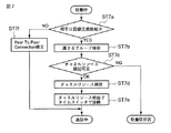
図7は、MGチャネルリソースを捕捉する際の呼制御部14Aの制御処理手順を示すフローチャートである。
Next, the operation of the IP terminal gateway system configured as described above will be described.
FIG. 7 is a flowchart showing a control processing procedure of the
ここでは、IP端末T1から非IP内線ELへ発呼した場合を考える。 Here, consider a case where a call is made from the IP terminal T1 to the non-IP extension EL.
IP端末T1より発呼が合った場合、呼制御部14Aは発呼に含まれる相手電話番号及び番号対応I/F属性記憶部17を参照して、IP端末T1が接続する相手がMGチャネルリソースを必要とする端末か否かを判定する(ステップST7a)。そして、相手がSIF1あるいはTIF1の場合は、該MGチャネルリソースが必要となるため、次の捕捉処理へ進む。
When the call is matched from the IP terminal T1, the
IP端末T1〜T3はその端末毎にMGチャネルリソースの必要度が持たされており、また、必要度に対応するリソース共有グループが定義されており、それらを組み合わせてIP端末T1〜T3がMGチャネルリソースを捕捉できる共有グループ番号が定義されている。 Each of the IP terminals T1 to T3 has a necessary degree of MG channel resources, and a resource sharing group corresponding to the necessary degree is defined, and the IP terminals T1 to T3 are combined with each other to generate an MG channel. A shared group number that can capture the resource is defined.
呼制御部14Aは、捕捉先チャネルリソース共有グループテーブル183からIP端末T1が属するセグメントA(SEGA)のグループ番号MG1を検索し(ステップST7b)、そのグループMG1にどれだけの空きMGチャネルリソースがあるか否かを、リソース数管理記憶部19Aから参照して判定する(ステップST7c)。ここでは、空きが8個あるため、捕捉可能である(OK)。従って、呼制御部14Aは共有リソース保持部12の共有グループMG1から1つのMGチャネルリソース(図1ではリソース1)を捕捉し(ステップST7d)、このMGチャネルリソース経由でタイムスイッチ11と接続する(ステップST7e)、結果、IP端末T1と非IP内線ELとの間に通信リンクが確立され通信中となる。
The
なお、上記ステップST7cにおいて、捕捉可能なMGチャネルリソースが無い場合(NG)、呼制御部14AはIP端末T1に対し非IP内線ELへの発信を拒否する。
In step ST7c, if there is no MG channel resource that can be captured (NG), the
また、上記ステップST7aにおいて、相手がIP端末T2である場合(NO)、呼制御部14AはPeer To Peer接続によりIP端末T1とIP端末T2との間に通信リンクを確立する(ステップST7f)。
In step ST7a, when the partner is the IP terminal T2 (NO), the
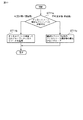
図8は、MGチャネルリソース返却時の呼制御部14Aの制御処理手順を示すフローチャートである。
通信が終了すると、呼制御部14AはIP端末T1に対し割り当てたMGチャネルリソースを共有リソース保持部12中の捕捉元の共有グループMG1に返却する(ステップST8a)。
FIG. 8 is a flowchart showing a control processing procedure of the
When the communication is completed, the
以上のように上記第1の実施形態では、ゲートウェイ装置1Aにおいて、共有リソース保持部12,13に保持されている複数のMGチャネルリソースを必要度に応じて共有グループMG1,MG2にグループ化し、これら共有グループMG1,MG2とIP端末T1〜T3とを対応付けたIP端末属性管理記憶部18及びリソース数管理記憶部19Aを設けて、例えばIP端末T1と非IP内線ELまたは外線SLとの間で通信を行なう際に呼制御部14AにてIP端末属性管理記憶部18及びリソース数管理記憶部19Aを参照することにより、共有リソース保持部12,13の中から捕捉するMGチャネルリソースを特定するようにしている。
As described above, in the first embodiment, in the
従って、例えば最も非IP内線ELまたは外線SLを利用する部署及び非IP内線ELまたは外線SLの利用回数が少ない部署が1つのシステムを共用する場合に、各部署ごとに使用するMGチャネルリソース数を限定することができ、これによりMGチャネルリソースを追加することなく、少数のMGチャネルリソースをそれよりも多数のIP端末T1〜T3で共用する場合に、MGチャネルリソースを効率良く割り当て、IP端末T1〜T3のユーザ別のきめ細かなサービスを実現できる。 Therefore, for example, when the department that uses the non-IP extension EL or the external line SL and the department that uses the non-IP extension EL or the external line SL most frequently share one system, the number of MG channel resources used for each department is set. Thus, when a small number of MG channel resources are shared by a larger number of IP terminals T1 to T3 without adding an MG channel resource, the MG channel resources are efficiently allocated, and the IP terminal T1 A fine service for each user of T3 can be realized.
また、上記第1の実施形態では、IP端末属性管理記憶部18及びリソース数管理記憶部19Aにおいて、LAN2,3のセグメントA,Bごとに共有グループMG1,MG2とIP端末T1〜T3とを対応付けるようにしているので、IP端末T1〜T3に対しセグメントA,B単位でMGチャネルリソースの割り当てを行なうことができる。
In the first embodiment, in the IP terminal attribute
さらに、上記第1の実施形態では、IP端末T3についてセグメントA,B間で必要度が同一の共有グループMG2に割り当てるように捕捉先チャネルリソース共有グループテーブル183に記憶しているので、IP端末T3がセグメントBからセグメントAへ移動したとしても、セグメントAでセグメントBの共有グループと同一の必要度の共有グループに属することになり、これによりセグメントBと同一のサービスを継続して利用できる。 Further, in the first embodiment, since the IP terminal T3 is stored in the capture destination channel resource sharing group table 183 so as to be assigned to the sharing group MG2 having the same degree of necessity between the segments A and B, the IP terminal T3 Even if the segment B moves from the segment B to the segment A, it belongs to the shared group having the same necessity level as the shared group of the segment B in the segment A, so that the same service as that of the segment B can be continuously used.
(第2の実施形態)
図9は、この発明の第2の実施形態に係わるIP端末ゲートウェイシステムの構成を示すブロック図である。なお、図9において、上記図1と同一部分には同一符号を付して詳細な説明を省略する。
(Second Embodiment)
FIG. 9 is a block diagram showing a configuration of an IP terminal gateway system according to the second embodiment of the present invention. In FIG. 9, the same parts as those in FIG.
図9において、呼制御部14Bに、リソース数変更制御部142を備えるようにしている。また、リソース数管理記憶部19Bには、図10に示すように、セグメントA,Bと、共有グループMG1,MG2と、一定時間毎外線呼量割合と、割当MGチャネルリソース数と、空きMGチャネルリソース数との対応関係を表すデータが記憶されている。
In FIG. 9, the call control unit 14B is provided with a resource number
リソース数変更制御部142は、一定時間ごとに外線SLの使用量(一定時間毎外線呼量割合)を監視し、この監視結果に基づいてリソース数管理記憶部19B中のセグメントA,Bごとの共有グループMG1,MG2に対する割当MGチャネルリソース数を変更する。
The resource number
次に、以上のように構成されたIP端末ゲートウェイシステムの動作を説明する。
図11は、MGチャネルリソース返却時の呼制御部14Bの制御処理手順を示すフローチャートである。
通信が終了すると、呼制御部14Bは捕捉元グループに返却可能か否かを判定する(ステップST11a)。返却した結果その時点で割り当てられている数を超えなければ(可)、呼制御部14Bは捕捉したMGチャネルリソースを捕捉元の共有グループに返却する(ステップST11b)。
Next, the operation of the IP terminal gateway system configured as described above will be described.
FIG. 11 is a flowchart showing the control processing procedure of the call control unit 14B when the MG channel resource is returned.
When the communication is completed, the call control unit 14B determines whether or not it can be returned to the capturing source group (step ST11a). As a result of the return, if the number assigned at that time is not exceeded (possible), the call control unit 14B returns the captured MG channel resource to the shared group of the capture source (step ST11b).
一方、越えてしまう場合(不可)、呼制御部14Bは捕捉したMGチャネルリソースを捕捉元グループ以外の他のグループへ返却する(ステップST11c)。ここでは同一セグメントに2グループしかないため、捕捉元以外のグループが一意に定まってしまうが、複数ある場合には、捕捉元以外の共有グループに関し、空きMGチャネルリソース数を割当数で割って残存率を計算し、その最も小さい共有グループへ返却する。 On the other hand, if it exceeds (impossible), the call control unit 14B returns the captured MG channel resource to a group other than the capturing source group (step ST11c). Here, since there are only two groups in the same segment, a group other than the capture source is uniquely determined. However, when there are a plurality of groups, the number of free MG channel resources is divided by the allocated number for the shared group other than the capture source. Calculate the rate and return it to the smallest shared group.
以上のように上記第2の実施形態では、呼制御部14Bにおいて、例えば外線SLへの呼量に応じてセグメントA,Bごとの各共有グループMG1,MG2のMGチャネルリソース数を最適なチャネルリソース数に可変設定するようにしているので、各共有グループMG1,MG2に属するIP端末T1〜T3に対し比較的柔軟にMGチャネルリソースを割り当てることができる。 As described above, in the second embodiment, in the call control unit 14B, for example, the number of MG channel resources of the shared groups MG1 and MG2 for each of the segments A and B is optimized according to the call volume to the external line SL. Since the number is variably set, the MG channel resource can be allocated relatively flexibly to the IP terminals T1 to T3 belonging to the shared groups MG1 and MG2.
(第3の実施形態)
この発明の第3の実施形態は、例えば時間帯に応じて共有グループMG1,MG2に割り当てるMGチャネルリソース数を固定にするか可変にするかを自動設定するようにしたものである。
(Third embodiment)
In the third embodiment of the present invention, for example, whether the number of MG channel resources allocated to the shared groups MG1 and MG2 is fixed or variable is automatically set according to the time zone.
図12は、この発明の第3の実施形態に係わるIP端末ゲートウェイシステムの構成を示すブロック図である。なお、図12において、上記図1と同一部分には同一符号を付して詳細な説明を省略する。 FIG. 12 is a block diagram showing the configuration of an IP terminal gateway system according to the third embodiment of the present invention. In FIG. 12, the same parts as those in FIG.
図12において、呼制御部14Cに、チャネル割当方式変更制御部143を備えている。さらに、リソース数管理記憶部19Cには、リソース数固定記憶部191と、リソース数可変記憶部192とが設けられる。リソース数固定記憶部191には、上記図6に示した記憶内容が記憶される。また、リソース数可変記憶部192には、上記図10に示した記憶内容が記憶される。
In FIG. 12, the call control unit 14C includes a channel assignment method
チャネル割当方式変更制御部143は、図13に示すように、タイマTMで計時される時刻が8:00になるとリソース数可変記憶部192からリソース数固定記憶部191に切り替え、17:00になるとリソース数固定記憶部191からリソース数可変記憶部192に切り替える。
As shown in FIG. 13, the channel allocation method
このように第3の実施形態であれば、通常の業務時間(8:00−17:00)は通信のトラフィックの変更がそれほどないと考えられ、また業務内容に合った優先的なMGチャネルリソース割付が必要なため固定割付とし、それ以外の時間(17:00−8:00)は、なるべく外線SLとの通話でのリソースブロックされる確率を減らすように外線呼量割合に連動して割り付けるというように、割付方式を自動的に変更することが可能となる。なお、切替条件としては、時間帯以外に例えば通信トラフィック等を用いることが可能である。 As described above, in the third embodiment, it is considered that there is not much change in communication traffic during normal business hours (8: 00-17: 00), and a preferential MG channel resource suitable for the business content. Since allocation is required, fixed allocation is used, and other times (17: 00-8: 00) are allocated in conjunction with the rate of external line call volume so as to reduce the probability of resource blocking in a call with external line SL as much as possible. Thus, it becomes possible to automatically change the allocation method. As the switching condition, it is possible to use, for example, communication traffic other than the time zone.
(その他の実施形態)
この発明は上記各実施形態に限定されるものではない。例えば上記各実施形態では、複数のMGチャネルリソースを2グループに分けた場合について説明したが、さらに多数のグループに分けるようにしてもよい。
(Other embodiments)
The present invention is not limited to the above embodiments. For example, in each of the above embodiments, the case where a plurality of MG channel resources are divided into two groups has been described. However, the MG channel resources may be further divided into a large number of groups.
また、上記各実施形態では、2セグメントの場合について説明したが、さらに多数のセグメントを有する場合でも同様に実施可能である。 In each of the above embodiments, the case of two segments has been described. However, the present invention can be similarly implemented even when there are a larger number of segments.
その他、システムの種類や構成、ゲートウェイ装置の構成、電話端末といったIP端末の種類、各記憶部の記憶内容、MGチャネルリソースの捕捉制御手順や返却制御手順等についても、この発明の要旨を逸脱しない範囲で種々変形して実施できる。 In addition, the type and configuration of the system, the configuration of the gateway device, the type of IP terminal such as a telephone terminal, the contents stored in each storage unit, the acquisition control procedure and return control procedure of the MG channel resource, etc. do not depart from the gist of the present invention. Various modifications can be made within the range.
1A,1B,1C…ゲートウェイ装置、2,3…LAN、11…タイムスイッチ、12,13…共有リソース保持部、14A,14B,14C…呼制御部、15…制御バス、16−1,16−2…音声バス、17…番号対応I/F属性記憶部、18…IP端末属性管理記憶部、19A,19B,19C…リソース数管理記憶部、141…チャネルリソース割当制御部、142…リソース数変更制御部、143…チャネル割当方式変更制御部、181…チャネルリソース必要度テーブル、182…チャネルリソース必要度対応共有グループ番号テーブル、183…捕捉先チャネルリソース共有グループテーブル、T1〜T3…IP端末、L1〜L3…LANインタフェース部、SIF1…内線インタフェース部、TIF1…外線インタフェース部、SL…外線、EL…非IP内線、TM…タイマ。
DESCRIPTION OF
Claims (7)
前記複数のメディアゲートウェイチャネルリソースを必要度に応じて分割して構成した複数のリソースグループごとに保持するプールと、
前記複数のリソースグループと、これらのリソースグループに属する通信端末との対応関係を表すグループテーブルを記憶する記憶手段と、
前記複数の通信端末のうちの任意の通信端末について前記メディアゲートウェイチャネルリソースの使用要求が発生した場合に、前記グループテーブルを参照し、この参照結果に基づいて前記任意の通信端末に対し該当するリソースグループの中の空きのメディアゲートウェイチャネルリソースを前記プールから読み出して割り当てる制御手段とを具備したことを特徴とするゲートウェイ装置。 A plurality of communication terminals are accommodated via a packet communication network, a communication network different from the packet communication network can be connected, and a plurality of media gateway channel resources are connected between the plurality of communication terminals and the communication network. In the gateway device that can be connected and communicate,
A pool for each of a plurality of resource groups configured by dividing the plurality of media gateway channel resources according to necessity; and
Storage means for storing a group table representing a correspondence relationship between the plurality of resource groups and communication terminals belonging to these resource groups;
When a request for using the media gateway channel resource is generated for an arbitrary communication terminal of the plurality of communication terminals, the group table is referred to, and the resource corresponding to the arbitrary communication terminal based on the reference result A gateway device comprising: a control unit that reads and allocates a free media gateway channel resource in the group from the pool.
前記プールは、前記セグメントごとに各リソースグループに属する複数のチャネルリソースを保持し、
前記記憶手段は、セグメントごとにグループテーブルを記憶することを特徴とする請求項1記載のゲートウェイ装置。 When the packet communication network is divided into a plurality of segments,
The pool holds a plurality of channel resources belonging to each resource group for each segment,
The gateway device according to claim 1, wherein the storage unit stores a group table for each segment.
前記プールに保持されるリソースグループごとのメディアゲートウェイチャネルリソース数を固定する第1のモードと、
前記プールに保持されるリソースグループごとのメディアゲートウェイチャネルリソース数を変更する第2のモードと、
前記条件に応じて、前記第1及び第2のモードを選択的に実行するモード選択制御手段とを備えたことを特徴とする請求項4記載のゲートウェイ装置。 The change control means includes
A first mode for fixing the number of media gateway channel resources for each resource group held in the pool;
A second mode for changing the number of media gateway channel resources for each resource group held in the pool;
5. The gateway apparatus according to claim 4, further comprising mode selection control means for selectively executing the first and second modes according to the condition.
前記複数のメディアゲートウェイチャネルリソースを必要度に応じて分割して構成した複数のリソースグループごとにプールに保持し、
前記複数のリソースグループと、これらのリソースグループに属する通信端末との対応関係を表すグループテーブルをメモリに記憶し、
前記複数の通信端末のうちの任意の通信端末について前記メディアゲートウェイチャネルリソースの使用要求が発生した場合に、前記グループテーブルを参照し、この参照結果に基づいて前記任意の通信端末に対し該当するリソースグループの中の空きのメディアゲートウェイチャネルリソースを前記プールから読み出して割り当てるようにしたことを特徴とするリソース割り当て方法。 A plurality of communication terminals are accommodated via a packet communication network, a communication network different from the packet communication network can be connected, and a plurality of media gateway channel resources are connected between the plurality of communication terminals and the communication network. In the resource allocation method used in the gateway device that enables communication by connecting to each other,
A plurality of resource groups configured by dividing the plurality of media gateway channel resources according to necessity are held in a pool,
Storing a group table representing a correspondence relationship between the plurality of resource groups and communication terminals belonging to these resource groups in a memory;
When a request for using the media gateway channel resource is generated for an arbitrary communication terminal of the plurality of communication terminals, the group table is referred to, and the resource corresponding to the arbitrary communication terminal based on the reference result A resource allocating method characterized in that an empty media gateway channel resource in a group is read from the pool and allocated.
Priority Applications (3)
| Application Number | Priority Date | Filing Date | Title |
|---|---|---|---|
| JP2006048818A JP2007228403A (en) | 2006-02-24 | 2006-02-24 | Gateway device and resource assigning method |
| CA002578976A CA2578976A1 (en) | 2006-02-24 | 2007-02-19 | Gateway apparatus and resource allocating method |
| US11/710,354 US20070202872A1 (en) | 2006-02-24 | 2007-02-23 | Gateway apparatus and resource allocating method |
Applications Claiming Priority (1)
| Application Number | Priority Date | Filing Date | Title |
|---|---|---|---|
| JP2006048818A JP2007228403A (en) | 2006-02-24 | 2006-02-24 | Gateway device and resource assigning method |
Publications (1)
| Publication Number | Publication Date |
|---|---|
| JP2007228403A true JP2007228403A (en) | 2007-09-06 |
Family
ID=38433850
Family Applications (1)
| Application Number | Title | Priority Date | Filing Date |
|---|---|---|---|
| JP2006048818A Pending JP2007228403A (en) | 2006-02-24 | 2006-02-24 | Gateway device and resource assigning method |
Country Status (3)
| Country | Link |
|---|---|
| US (1) | US20070202872A1 (en) |
| JP (1) | JP2007228403A (en) |
| CA (1) | CA2578976A1 (en) |
Cited By (1)
| Publication number | Priority date | Publication date | Assignee | Title |
|---|---|---|---|---|
| JP2009225102A (en) * | 2008-03-17 | 2009-10-01 | Nec Engineering Ltd | Line switching system |
Families Citing this family (1)
| Publication number | Priority date | Publication date | Assignee | Title |
|---|---|---|---|---|
| CN109413598B (en) * | 2018-11-26 | 2021-07-23 | 京信通信系统(中国)有限公司 | Resource allocation and management method and device |
Family Cites Families (8)
| Publication number | Priority date | Publication date | Assignee | Title |
|---|---|---|---|---|
| WO1996027155A2 (en) * | 1995-02-13 | 1996-09-06 | Electronic Publishing Resources, Inc. | Systems and methods for secure transaction management and electronic rights protection |
| US6345041B1 (en) * | 1996-10-24 | 2002-02-05 | Hewlett-Packard Company | Method and apparatus for automatic load-balancing on multisegment devices |
| US7333505B2 (en) * | 2000-12-18 | 2008-02-19 | Nortel Networks Limited | Transaction management for interworking between disparate networks |
| US20040143644A1 (en) * | 2003-01-21 | 2004-07-22 | Nec Laboratories America, Inc. | Meta-search engine architecture |
| AU2003901931A0 (en) * | 2003-04-23 | 2003-05-15 | Thiss Pty Ltd | Radio network assignment and access system |
| US7953703B2 (en) * | 2005-02-17 | 2011-05-31 | International Business Machines Corporation | Creation of highly available pseudo-clone standby servers for rapid failover provisioning |
| KR100963551B1 (en) * | 2005-07-08 | 2010-06-16 | 후지쯔 가부시끼가이샤 | Radio resource assigning method and communication apparatus |
| US20070050710A1 (en) * | 2005-08-31 | 2007-03-01 | Redekop Christopher K | Graphical user interface for a web application |
-
2006
- 2006-02-24 JP JP2006048818A patent/JP2007228403A/en active Pending
-
2007
- 2007-02-19 CA CA002578976A patent/CA2578976A1/en not_active Abandoned
- 2007-02-23 US US11/710,354 patent/US20070202872A1/en not_active Abandoned
Cited By (1)
| Publication number | Priority date | Publication date | Assignee | Title |
|---|---|---|---|---|
| JP2009225102A (en) * | 2008-03-17 | 2009-10-01 | Nec Engineering Ltd | Line switching system |
Also Published As
| Publication number | Publication date |
|---|---|
| US20070202872A1 (en) | 2007-08-30 |
| CA2578976A1 (en) | 2007-08-24 |
Similar Documents
| Publication | Publication Date | Title |
|---|---|---|
| CN1097375C (en) | Variable communication bandwidth for providing automatic call back and call hold | |
| EP2371086B1 (en) | Network node and method for controlling resources in a communication network | |
| US8873374B2 (en) | Accelerated recovery during negotiation between a media gateway and a media gateway controller | |
| JP2007228403A (en) | Gateway device and resource assigning method | |
| US20030165145A1 (en) | Apparatus and method for compulsively receiving multi-calls over internet protocol phones in internet protocol telephony system | |
| US20100027528A1 (en) | Notification of Impending Media Gateway Resource Exhaustion | |
| JP2008092102A (en) | Telephone switching system | |
| JP2005269434A (en) | Voip voice communication system | |
| JP2017011575A (en) | Pbx cooperation system and communication control method therefor | |
| JP5169347B2 (en) | Circuit switching system | |
| JP4189360B2 (en) | Telephone exchange device and network telephone system | |
| TW201238318A (en) | Method for communication and component in a communication network | |
| JP2005333312A (en) | Load decentralization system of media gateway device | |
| JP4513549B2 (en) | Private branch exchange | |
| EP1299995B1 (en) | Telesystem with coupling device and a method in connection therewith | |
| JP2004312380A (en) | Band control system | |
| JP2007243745A (en) | Call center system | |
| JP5061222B2 (en) | Resource management method and resource management control device | |
| KR100511664B1 (en) | A traffic-reduced method for managing the number of trunk line and a traffic-reduced soft switch | |
| JPH08237271A (en) | Dynamic band change control method for virtual path | |
| JP2007259312A (en) | Server device | |
| JP2010109878A (en) | Main apparatus and bandwidth allocating method | |
| JP2004274392A (en) | Switching network system and telephone exchange equipment therefor | |
| JP2000244638A (en) | Private switchboard, communication method and storage medium | |
| JP2007036599A (en) | Phone system |