JP2006198017A - Robot toy - Google Patents
Robot toy Download PDFInfo
- Publication number
- JP2006198017A JP2006198017A JP2005010771A JP2005010771A JP2006198017A JP 2006198017 A JP2006198017 A JP 2006198017A JP 2005010771 A JP2005010771 A JP 2005010771A JP 2005010771 A JP2005010771 A JP 2005010771A JP 2006198017 A JP2006198017 A JP 2006198017A
- Authority
- JP
- Japan
- Prior art keywords
- emotion
- robot toy
- light
- level
- value
- Prior art date
- Legal status (The legal status is an assumption and is not a legal conclusion. Google has not performed a legal analysis and makes no representation as to the accuracy of the status listed.)
- Pending
Links
Images


Classifications
-
- G—PHYSICS
- G06—COMPUTING; CALCULATING OR COUNTING
- G06N—COMPUTING ARRANGEMENTS BASED ON SPECIFIC COMPUTATIONAL MODELS
- G06N3/00—Computing arrangements based on biological models
- G06N3/004—Artificial life, i.e. computing arrangements simulating life
- G06N3/008—Artificial life, i.e. computing arrangements simulating life based on physical entities controlled by simulated intelligence so as to replicate intelligent life forms, e.g. based on robots replicating pets or humans in their appearance or behaviour
-
- A—HUMAN NECESSITIES
- A63—SPORTS; GAMES; AMUSEMENTS
- A63H—TOYS, e.g. TOPS, DOLLS, HOOPS OR BUILDING BLOCKS
- A63H11/00—Self-movable toy figures
-
- A—HUMAN NECESSITIES
- A63—SPORTS; GAMES; AMUSEMENTS
- A63H—TOYS, e.g. TOPS, DOLLS, HOOPS OR BUILDING BLOCKS
- A63H33/00—Other toys
- A63H33/22—Optical, colour, or shadow toys
-
- A—HUMAN NECESSITIES
- A63—SPORTS; GAMES; AMUSEMENTS
- A63H—TOYS, e.g. TOPS, DOLLS, HOOPS OR BUILDING BLOCKS
- A63H2200/00—Computerized interactive toys, e.g. dolls
Abstract
Description
本発明はロボット玩具に係り、特に安価なロボット玩具に適用できる。 The present invention relates to a robot toy, and can be applied to a particularly inexpensive robot toy.
近年、ユーザからの「叩く」又は「撫でる」といった働きかけや、周囲の環境などに基づいて自己の感情を生成し、生成した感情を発光素子の発光パターンや音楽などの音声によって表現するロボット玩具が提案され、商品化されている(例えば、特許文献1参照)。 In recent years, robot toys that generate user's emotions based on user's "striking" or "blowing" actions, the surrounding environment, etc., and expressing the generated emotions by the light emission patterns of the light emitting elements and music etc. Proposed and commercialized (see, for example, Patent Document 1).
例えば、特許第3277500号公報には、「喜び」や「怒り」の感情を表現するための、その感情に応じた形状及び発光色を有するLED(Light Emitting Diode)をロボット玩具の頭部に配置すると共に、これを発光時にのみ外部から目視できるように半透明カバーで覆い、ロボット玩具の感情に応じてこれらLEDを点滅駆動することが開示されている。 For example, in Japanese Patent No. 3277500, an LED (Light Emitting Diode) having a shape and emission color corresponding to the emotion for expressing the emotion of “joy” or “anger” is arranged on the head of the robot toy. In addition, it is disclosed that this is covered with a translucent cover so that it can be seen from the outside only during light emission, and these LEDs are driven to blink according to the emotion of the robot toy.
またこの特許第3277500号公報には、「喜び」や「怒り」の感情に応じた形状及び発光色を有するLEDに代えて、多数の発光素子をマトリクス状に配置し、これら発光素子を選択的に点滅駆動するようにしてロボット玩具の感情を表現することも開示されている。
ところで、ロボット玩具の感情を発光素子の発光パターンで表現する場合、「喜び」や「怒り」等の各種感情に応じた形状及び発光色を有するLEDをそれぞれ用意するよりも、上述のように多数の発光素子をマトリクス状に配置し、これらを感情に応じて選択的に点滅駆動する手法を採用した方が多様な発光パターンで感情を表現することができる。 By the way, when expressing the emotion of the robot toy with the light emission pattern of the light emitting element, as described above, there are many more than preparing LEDs having shapes and emission colors according to various emotions such as “joy” and “anger”. It is possible to express emotions with various light emission patterns by adopting a method in which the light emitting elements are arranged in a matrix and these are selectively driven to blink according to emotions.
しなしながら、安価なロボット玩具では、発光素子をマトリクス状に配置することはコスト的に困難であり、限られたコストの中で、ロボット玩具の感情を発光素子の発光パターンで効果的に表現できるような工夫が必要となる。そして、このようにロボット玩具の感情を発光素子の発光パターンで効果的に表現できれば、そのロボット玩具に対するユーザの興味を向上させて、「玩具」としての商品価値を向上させ得るものと考えられる。 However, with inexpensive robot toys, it is difficult to arrange the light emitting elements in a matrix, and the emotions of the robot toys are effectively expressed by the light emitting pattern of the light emitting elements within the limited cost. A device that can be used is necessary. If the emotion of the robot toy can be effectively expressed by the light emission pattern of the light emitting element as described above, it is considered that the user's interest in the robot toy can be improved and the commercial value as a “toy” can be improved.
本発明はこのような問題に鑑みてなされたものであり、安価に構築しながら感情表現を効果的に行い得るロボット玩具を提供することを目的とするものである。 The present invention has been made in view of such problems, and an object of the present invention is to provide a robot toy that can effectively express emotions while being constructed at low cost.
上記の課題を解決するため、本発明のロボット玩具は、少なくとも2色の光を同時に又は個別に発光可能な第1の光源と、第1の光源の周囲に配置された5つ以上の第2の光源と、感情を構成する少なくとも2種類の感情パラメータを記憶するメモリと、外部からの操作入力に基づいて感情パラメータの値を増減させる制御手段とを有し、制御手段は、各感情パラメータの値の組み合せに対応した発光パターンで第1及び又は第2の光源を発光させる。 In order to solve the above-described problems, a robot toy according to the present invention includes a first light source capable of emitting light of at least two colors simultaneously or individually, and five or more second light sources arranged around the first light source. , A memory for storing at least two types of emotion parameters constituting the emotion, and a control means for increasing or decreasing the value of the emotion parameter based on an external operation input. The first and / or second light source is caused to emit light with a light emission pattern corresponding to a combination of values.
本発明によれば、少ない光源数で多様な感情表現を行うことができ、かくして安価に構築しながら感情表現を効果的に行うことができる。 According to the present invention, various emotional expressions can be performed with a small number of light sources, and thus emotional expressions can be effectively performed while being constructed at low cost.
以下、各図を参照して本実施の形態について説明する。 Hereinafter, the present embodiment will be described with reference to the drawings.
(1)ロボット玩具の構成
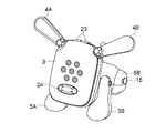
図1は、本実施の形態に係わるロボット玩具1を示すものである。このロボット玩具1は、全体として犬などの動物が座った状態に似せた外観形状を有している。すなわちロボット玩具1は、胴体部2の前端部から垂直方向に延びた軸に対して回動自在に頭部が連結され、当該頭部3の上端左右両側にそれぞれ耳部4A,4Bが可動自在に取り付けられている。また胴体部2の左右両側面の前端部には、それぞれ丸みを帯びた棒形状の前足部5A,5Bが人手により可動自在に連結され、胴体部2の左右両側面の後端部には、それぞれ前足部より短い突起状の後足部6A,6Bが胴体部2と一体に成型されている。さらに胴体部2の上面後端部近傍にはジョイステック状の尻尾スイッチ7が可動自在に取り付けられている。
(1) Configuration of Robot Toy FIG. 1 shows a
胴体部2は、全体として丸みを帯びた直方体形状に形成されており、図2に示すように、その内部に、ロボット玩具1全体の動作制御を司る制御部10、モータ駆動部11及びサウンドアンプ部12などが形成された基板13と、マイクロホン14及びスピーカ15などのデバイスとなどが収納されている。また胴体部2の一方の後足部6Bにはイヤホンジャックが配設されている。
The
頭部3は、全体として胴体部2よりも平たい丸みを帯びた直方体形状に形成されており、その内部に光センサ20、複数のLEDを有するLED表示部21などのデバイスと、モータ22を動力源として頭部3や各耳部4A,4Bを駆動する後述の駆動機構34(図3)となどが収納されている。また頭部3における上端部には押圧スイッチでなる頭スイッチ23が配設され、頭部3における鼻の位置には押圧スイッチでなる鼻スイッチ24が配設されている。ロボット玩具1全体としては、前足部5A,5Bのほうが後足部6A,6Bよりも長いため、頭部3の一面が載置面に対して斜め上方を向くようになり、この一面にLED表示部21の表示面を配置することで、ユーザに表示を見やすくすることができるようになされている。
The
そして胴体部2のマイクロホン14は、周囲の音を集音し、得られた音声信号S1を制御部10に送出する。また頭部3の光センサ20は、周囲の明るさを検出し、検出結果を明るさ検出信号S2として制御部10に送出する。さらに尻尾スイッチ7、頭スイッチ23及び鼻スイッチ24は、それぞれユーザから与えられた「倒す」又は「押す」といった物理的な働きかけを検出し、検出結果を操作検出信号S3A〜S3Cとして制御部10に送出する。なお、制御部10には、イヤホンジャック16を介して外部の音響機器から供給される音声信号S4も与えられる。
The
制御部10は、CPU(Central Processing Unit)10A、メモリ10B及びアナログ/ディジタル変換回路10C等などを含むマイクロコンピュータ構成でなり、マイクロホン14からの音声信号S1及び光センサ20からの明るさ検出信号S2と、尻尾スイッチ7、頭スイッチ23及び鼻スイッチ24からの各操作検出信号S3A〜S3Cとに基づいて周囲の状況やユーザからの働きかけの有無を認識する。
The
そして制御部10は、この認識結果と予めメモリ10Bに格納されているプログラムとに基づいて、モータ駆動部11にモータ駆動信号S4を送出してモータ22を駆動させることによりロボット玩具1の頭部3を傾けさせたり、耳部4A,4Bを開閉させる動作を発現させる。また制御部10は、必要に応じて所定の音声信号S5をサウンドアンプ部12を介してスピーカ15に与えることにより当該音声信号S5に基づく音や音楽をスピーカ15から出力させたり、LED表示部21に所定の駆動信号S6を与えることにより当該LED表示部21のLEDを所定の発光パターンで点滅駆動させる。
Then, the
なお、頭部3の具体的な構成を図3に示す。この図3からも明らかなように、ロボット玩具1の頭部3は、当該頭部3の背面側の外観形状を形成する第1の筐体半体30と、当該頭部3の正面側の外観形状を形成する第2の筐体半体31と、当該頭部3の左右側面をそれぞれ形成するコ字状の第1及び第2の筐体側面部材32とから構成される筐体の内部に、駆動機構部34、当該駆動機構部34のカバー35、LED表示部21、光漏れ防止部材36及びフィルタカバー37が矢印aで示す正面方向に順次積層するように収納されることにより構成されている。
A specific configuration of the
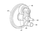
駆動機構部34においては、図4に示すように、モータ22の出力軸に図示しないウオームギアが取り付けられ、このウオームギアがギア40及び当該ギア40と同軸かつ一体に形成されたギア41を介してギア42と歯合している。また、このギア42が取り付けられた軸体43には、図5に示すように、一端部に錘44が取り付けられた可動部材45が回転自在に取り付けられており、この可動部材45の他端側に回転自在に取り付けられた振子ギア46がギア42と同軸かつ一体に形成されたギア47と歯合している。また振子ギア46の左右両側には、可動部材45が軸体43を中心として回転したときに振子ギア46と歯合し得るように、それぞれ第1又は第2の連結ギア48,49が配設されている。
As shown in FIG. 4, in the
これにより駆動機構部34においては、モータ22を正転駆動したときに、その回転力がモータ22の出力軸に取り付けられたウオームギアからギア42までのギア列を介してギア47に伝達され、この回転力に基づいてギア47が振子ギア46と一体に可動部材45を図4の時計回り方向に回転させることにより、振子ギア46を第1の連結ギア48と歯合させることができ、逆にモータ22を反転駆動したときに、その回転力に基づいてギア47が可動部材45を図4の反時計回り方向に回転させることにより、振子ギア46を第2の連結ギア49と歯合させることができるようになされている。
Thereby, in the
この場合、第1の連結ギア48は第1のカムギア50と歯合しており、この第1のカムギア50の下面側には、図6に示すように、所定形状のカム50Aが形成されている。そしてこのカム50Aは、図4において矢印bで示す上下に移動自在に配設された図7に示すような昇降部材51の係合穴51Aに嵌め込まれており、かくして第1のカムギア50を回転させることによって、カム50Aにより昇降部材51を昇降させることができるようになされている。
In this case, the first connecting
さらに昇降部材51の上端部には、この図7からも明らかなように、第1の筐体半体30に植設された軸体52(図4)を基準として左右対称位置に位置するように第1及び第2の軸体53A,53Bが植設されており、図4に示すように、これら第1及び第2の軸体53A,53Bに耳駆動部材54が取り付けられている。
Further, as is clear from FIG. 7, the upper end portion of the elevating / lowering
耳駆動部材54は、図8に示すように、それぞれ弾性材からなるピンセット形状の第1及び第2のばね部60A,60Bの各根元部を筒部61を介して一体にかつ屈曲自在に連結することにより形成されている。そして耳駆動部材54は、これら第1及び第2のばね部60A,60Bの根元部近傍にそれぞれ配設された第1又は第2の係合部62A,62Bの各孔62AX,62BXを、それぞれ昇降部材51の対応する第1又は第2の軸体53A,53Bと嵌め合わせ、かつ筒部61を軸体52と嵌め合わせるようにして、昇降部材51に取り付けられている。
As shown in FIG. 8, the
これにより駆動機構部34においては、昇降部材51が昇降駆動されたときに、当該昇降部材51の第1及び第2の軸体53A,53Bが軸体52に対して上下方向に移動することによって、耳駆動部材54の第1及び第2の係合部62A,62Bと一体に第1及び第2のばね部60A,60Bを開閉するように駆動することができるようになされている。
As a result, in the
さらに耳駆動部材54の第1及び第2のばね部60A,60Bには、対応する耳部4A,4Bの下端部がそれぞれ嵌めこまれると共に、各耳部4A,4Bは、それぞれ下端部近傍が第1の筐体半体30の上端左右両側において軸支されており、かくして耳駆動部材54の第1及び第2のばね部60A,60Bの開閉動作に連動して耳部4A,4Bを開閉駆動し得るようになされている。
Further, the first and
これにより駆動機構部34においては、モータ22を正転駆動させたときに、振子ギア46(図5)が第1の連結ギア48と歯合してモータ22の回転出力を第1のカムギア50に伝達し、この回転出力に基づいて第1のカムギア50のカム50Aが昇降部材51を昇降させて耳駆動部材54の第1及び第2のばね部60A,60Bを開閉駆動することで、耳部4A,4Bを開閉するように動作させ得るようになされている。
Thus, in the
これに対して、第2の連結ギア49は第2のカムギア63と歯合しており、この第2のカムギア63の下面側には、図9(A)に示すように、所定形状のカム63Aが形成されている。また第2のカムギア63の下側には、胴体部2に固定された軸体64に対してさらに固定された二股部材65の2本の平行な腕部65A,65Bが伸びている。そして第2のカムギア63のカム63Aは、この二股部材65のこれら2本の腕部65A,65Bの間に嵌め込まれている。
On the other hand, the second connecting
これにより駆動機構部34においては、モータ22を逆転駆動させたときに、振子ギア46(図5)が第2の連結ギア49と歯合してモータ22の回転出力を第2のカムギア63に伝達し、この回転出力に基づいて第2のカムギア63のカム63Aが図9(B)及び(C)のように二股部材65の腕部65A,65Bを押すことにより、その反作用によって頭部3を軸体64を中心として左右方向に揺れるように動作させ得るようになされている。なお、かかるモータ22の正転と逆転は、その回転方向がある回転方向に対して逆方向の回転であれば良く、正転と逆転が、それぞれ時計回りか反時計回りか等に限定されるものではない。
As a result, in the
一方、LED表示部21においては、図3に示すように、基板66上に7個のLED21A〜21Gが所定の位置関係で配設されることにより構成されている。この7個のLED21A〜21Gの位置関係及びそれぞれの発光色については後述する。
On the other hand, as shown in FIG. 3, the
光漏れ防止部材36は、光を通さない例えば黒色の樹脂材又はゴム材等を用いて形成されており、LED表示部21の基板66に密着するように取り付けられている。なお鼻スイッチ24の押圧部24A及び接点部24Bは、この光漏れ防止部材36の下端部に固定されている。
The light
そして、この光漏れ防止部材36には、LED表示部21の各LED21A〜21Gにそれぞれ対応させて合計7つの穴36A〜36Gが設けられており、かくしてこの光漏れ防止部材36をLED表示部21の基板66に取り付けたときに、これら各穴36A〜36Gをそれぞれ介してLED表示部21の対応するLED21A〜21Gをフィルタカバー37側に露出させ得るようになされている。
The light
またこの光漏れ防止部材36の厚みは、LED表示部21の基板66からフィルタカバー37までの隙間と同じ大きさに設定されており、これによりLED表示部21の各LED21A〜21Gからそれぞれ発射された光を、他のLED21A〜21Gから発射された光と混じわらせることなくフィルタカバー37の方向に出射させ得るようになされている。
Further, the thickness of the light
さらにフィルタカバー37は半透明な樹脂材を用いて形成されると共に、第2の筐体半体31は透明な樹脂財を用いて形成されており、これによりLED表示部21のLED21A〜21Gが消灯しているときには当該LED21A〜21Gを外部から認識させず(見えず)、LED21A〜21Gが点灯したときに、図10に示すように、このLED21A〜21Gを外部から認識し得る(このLED21A〜21Gから発射された光を見ることができる)ようになされている。またこのようにフィルタカバー37を設けることによって、LED21A〜21Gが点灯したときに、当該点灯したLED21A〜21Gの箇所のみがピンポイント的に明るくならず、光漏れ防止部材36に設けられた対応する穴36A〜36Gの形状全体が一様な明るさとなるように光を拡散させ得るようになされている。
Further, the
この場合、フィルタカバー37は白色に形成されており、これによりフィルタカバー37を通して外部から見えるLED表示部21の各LED21A〜21Gから発射された光をフィルタカバー37によってくすませることなく、白色内にほのかに浮かび上らせることができるようになされている。
In this case, the
(2)ロボット玩具の感情表現
(2−1)ロボット玩具の感情表現
次に、このロボット玩具1の感情表現について説明する。このロボット玩具1には、制御部10(図2)が、ユーザからの働きかけの内容や働きかけの有無に基づいてそのときのロボット玩具1の感情を生成し、その感情の種類及び度合いに応じた発光パターンでLED表示部21の各LED21A〜21Gを点滅させることによって、そのときのロボット玩具1の感情を表現する感情表現機能が搭載されている。
(2) Emotional expression of robot toy (2-1) Emotional expression of robot toy Next, the emotional expression of the
図11は、このようなロボット玩具1の感情表現に用いられるLED表示部21の各LED21A〜21Gの配置関係を示すものである。この図11からも明らかなように、LED表示部21においては、頭部3における幅方向の中心線上の所定位置に1つのLED21Aが配置され、このLED21Aを中心として、同心円上に、当該LED21Aから等距離にかつ相互に等間隔に位置するように残りの6個のLED21B〜21Gが配設されている。つまり、周囲の6個のLED21B〜21Gは、中央のLED21Aを中心とする正六角形の各頂点位置にそれぞれ位置するような位置関係で配置されている。
FIG. 11 shows the arrangement relationship of the
このうち中央のLED21Aとしては、緑色、赤色及び青色の3色を同時又は別個に発光し得るものが用いられている。また、他の周囲のLED21B〜12Gとしては、緑色及び赤色の2色を同時又は別個に発光し得るものが用いられている。従って、周囲のLED21B〜12Gについては、緑色及び赤色の2色を同時に点灯させることで橙色に発光させることができるようになされている。
Among these, as the
一方、ロボット玩具1の感情は、図12に示すように、「興奮レベル」及び「愛情レベル」をそれぞれ表す2つのパラメータ(以下、これらを感情パラメータと呼ぶ)によって定義されている。これら2つの感情パラメータは、メモリ10Bに保持されており、それぞれ「−8」乃至「8」の範囲の値をとる。
On the other hand, as shown in FIG. 12, the emotion of the
そして、「興奮レベル」及び「愛情レベル」の各感情パラメータの値が共に0又は正の範囲に「喜び」及び「大好き」という感情が対応付けられ、「愛情レベル」の感情パラメータの値が0又は正で、「興奮レベル」の感情パラメータの値が負の範囲に「通常」及び「落ち着き」という感情が対応付けられている。 The emotion parameters “excitement level” and “love level” are both 0 or positive and the emotions “joy” and “love” are associated with each other, and the emotion parameter value of “love level” is 0. Alternatively, the emotions “normal” and “calmness” are associated with the range in which the emotion parameter value of “excitement level” is negative and negative.
また「興奮レベル」及び「愛情レベル」の各感情パラメータの値が共に負の範囲に「寂しい」及び「落ち込み」という感情が対応付けられ、さらに「興奮レベル」の感情パラメータの値が0又は正で、「愛情レベル」の感情パラメータの値が負の範囲に「怒り」及び「嫌い」という感情が対応付けられている。 In addition, emotional values of “loneliness” and “depression” are associated with negative ranges of the emotion parameter values of “excitement level” and “love level”, and the emotion parameter value of “excitement level” is 0 or positive. Thus, emotions of “anger” and “dislike” are associated with a negative range of emotion parameter values of “love level”.
さらに、このような「喜び」等の感情の度合い(感情の強さ)は、「興奮レベル」及び「愛情レベル」の各感情パラメータの値の大きさによって表現され、これら感情パラメータの値の絶対値が大きければ大きいほどその感情の度合いが大きいことを意味する。 Furthermore, the degree of emotion (emotion intensity) such as “joy” is expressed by the magnitude of the emotion parameter values of “excitement level” and “love level”. The larger the value, the greater the degree of emotion.
従って、例えばある時間における「興奮レベル」及び「愛情レベル」の感情パラメータの値が共に「8」であるときには、これら感情パラメータの値が共に正の値であることから、ロボット玩具1の感情が「喜び」及び「大好き」という感情を抱いており、さらにこれら感情パラメータの値が共に最大値であることから、その「喜び」及び「大好き」という感情の度合いが最大となっていることを表すことになる。 Therefore, for example, when the values of the emotion parameters of “excitement level” and “love level” at a certain time are both “8”, the values of these emotion parameters are both positive. The emotional value of “joy” and “love” is held, and the values of these emotion parameters are both maximum values, indicating that the degree of emotion of “joy” and “love” is the maximum. It will be.
そして制御部10は、尻尾スイッチ7や頭スイッチ23及び鼻スイッチ24からそれぞれ与えられる操作検出信号S3A〜S3Cに基づいて、ユーザから尻尾スイッチ7や頭スイッチ23及び鼻スイッチ24を「倒す」又は「押す」という働きかけが与えられた場合や、この働きかけが一定時間行われなかったときに、「興奮レベル」及び「愛情レベル」の感情パラメータの値を「−8」乃至「8」の範囲で増減させることにより、感情を変化させるようになされている。
Then, based on the operation detection signals S3A to S3C given from the
この場合、かかるユーザからの働きかけに応じて「興奮レベル」及び「愛情レベル」の各感情パラメータをどのように増減させるかは予め定められており、例えば鼻スイッチ24が押圧操作された場合には、「興奮レベル」及び「愛情レベル」の各感情パラメータの値がそれぞれ1増加され、頭スイッチが押圧操作された場合には、「興奮レベル」の感情パラメータの値が1減少されると共に「愛情レベル」の感情パラメータの値が1増加される。
In this case, how to increase / decrease the emotion parameters of “excitement level” and “love level” in accordance with the user's action is predetermined. For example, when the
従って、ユーザは、ロボット玩具1の鼻スイッチ24を押圧操作することによって、ロボット玩具1の感情を「喜び」及び「大好き」という感情に移行させたり、この「喜び」及び「大好き」という感情の度合いを大きくさせたりすることができ、頭スイッチ23を押圧操作することによって、ロボット玩具1の感情を「通常」又は「落ち着き」という感情に移行させたり、この「通常」又は「落ち着き」の感情の度合いを大きくさせたりすることができる。
Therefore, the user moves the emotion of the
また制御部10は、尻尾スイッチ7が揺動操作された場合には、「興奮レベル」の感情パラメータの値を1増加させる一方、「愛情レベル」の感情パラメータの値を「−8」乃至「8」の範囲で1ずつ増加又は減少させながら往復させる。従って、ユーザは、ロボット玩具1の尻尾スイッチ7を揺動操作することによって、ロボット玩具1の感情を「怒り」及び「嫌い」という感情と、「落ち込み」及び「寂しがる」という感情とのいずれかに移行させたり、その感情の度合いを大きくさせたりすることができる。
Further, when the
さらに制御部10は、ユーザから尻尾スイッチ7や頭スイッチ23及び鼻スイッチ24を「倒す」又は「押す」という働きかけが一定期間(例えば30秒)与えられなかった場合には、「興奮レベル」及び「愛情レベル」の各感情パラメータの値をそれぞれ1減少させる。従って、このときロボット玩具1は、自己の感情を「落ち込み」及び「寂しい」という感情に移行させてゆき、その感情の度合いを大きくさせるとなる。
Further, when the user is not given an action to “depress” or “push” the
そして制御部10は、このようにして感情の「興奮レベル」及び「愛情レベル」の感情パラメータの値を変更したときには、変更後のこれら2つの感情パラメータの値によって決定されるそのときのロボット玩具1の感情とその度合いとに応じて、LED表示部21の各LED21A〜21Gをその感情とその度合いに応じた発光パターンで点滅させるようになされている。
When the
実際上、制御部10は、上述のようにして感情の「興奮レベル」及び「愛情レベル」の感情パラメータの値を変更したときには、そのときの「興奮レベル」及び「愛情レベル」の各感情パラメータの値をメモリ10Bから読み出し、これら読み出した2つの感情パラメータの値を判別することにより、そのときのロボット玩具1の感情が、「喜び」及び「大好き」という感情(「興奮レベル」及び「愛情レベル」の各感情パラメータの値が共に0又は正の範囲)と、「通常」及び「落ち着き」という感情(「愛情レベル」の感情パラメータの値が0又は正で、「興奮レベル」の感情パラメータの値が負)と、「落ち込み」及び「寂しい」という感情(「興奮レベル」及び「愛情レベル」の各感情パラメータの値が共に負)と、「怒り」及び「嫌い」という感情(「興奮レベル」の感情パラメータの値が0又は正で、「愛情レベル」の感情パラメータの値が負)とのうちのどれに該当するかを判断する。
In practice, when the
そして制御部10は、この後さらに「興奮レベル」及び「愛情レベル」の感情パラメータの値をそれぞれ判別することにより、そのときのロボット玩具1の感情の度合いを判断し、これらの判断結果に基づいてLED表示部21を制御することにより、そのときのロボット玩具1の感情のその度合いと対応付けられた発光パターンで当該LED表示部21のLED21A〜21Gを点滅させる。
Then, the
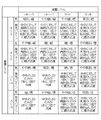
そのための手段として、例えば図13に示すように、「興奮レベル」及び「愛情レベル」の各感情パラメータの値の組合せに対してどのような発光パターンでLED表示部21の各LED21A〜12Gを点滅させるかが予め定められており、これらすべての発光パターンについて、LED表示部21のLED21A〜21Gをその発光パターンで点滅駆動するためにとのLED21A〜21Gをどのようなタイミングで点滅させるかが定義されたプログラム(以下、これをLED駆動プログラムと呼ぶ)がメモリ10Bに予め格納されている。
For example, as shown in FIG. 13, the
そして制御部10は、上述のようにしてロボット玩具1の感情及びその度合いを判断した後に、かかるLED駆動プログラムに従って、LED表示部21のLED21A〜21Gを、そのときのロボット玩具1の感情及びその度合いに応じた発光パターンで点滅させる。
Then, after determining the emotion and the degree of the
なお、この図13からも明らかなように、このようなLED表示部21におけるLED21A〜21Gの発光パターンは、図14に示すように、中央のLED21Aに対して周囲のLED21B〜21Gのみを時計回り方向に1個ずつ点滅させるように、各LED21B〜21Gをそれぞれ隣り合うLED21B〜LED21Gに対して順次点灯と消灯を繰り返えさせる発光パターンを基本としている。以下においては、この発光パターンを基本発光パターンと呼ぶ。
As is apparent from FIG. 13, the light emission patterns of the
この基本発光パターンは、「落ち込み」及び「寂しい」以外の感情を表現する発光パターンとして用いられており、「喜び」及び「大好き」(「興奮レベル」及び「愛情レベル」の各感情パラメータの値が共に正)の感情のときには対応するLED21B〜21Gが橙色に発光駆動され、「通常」及び「落ち着き」(「興奮レベル」の感情パラメータの値が負で、「愛情レベル」の感情パラメータが0又は正)の感情のときには対応するLED21B〜21Gが緑色に発光駆動され、「怒り」及び「嫌い」(「興奮レベル」の感情パラメータの値が0又は正で、「愛情レベル」の感情パラメータの値が負)の感情のときには対応するLED21B〜21Gが緑色に発光駆動される。またロボット玩具の感情が「落ち込み」及び「寂しい」(「興奮レベル」及び「愛情レベル」の各感情パラメータの値が共に負)であるときには、周囲のLED21B〜21Gは発光せず、中央のLED21Aのみが青色に点滅するように駆動される。
This basic light emission pattern is used as a light emission pattern expressing emotions other than “depressed” and “lonely”, and values of emotion parameters of “joy” and “love” (“excitement level” and “love level”). When the emotions are both positive, the corresponding
さらにLED表示部21におけるLED21A〜1Gの発光パターンは、「喜び」及び「大好き」の感情と、「通常」及び「落ち着き」の感情と、「怒り」及び「嫌い」の感情との場合には、その感情の度合いが大きければ大きいほど光がより速く回転するように、すなわち周囲のLED21B〜21Gの点滅周期が速くなるように規定され、「落ち込み」及び「寂しい」の感情の場合には、その感情の度合いが大きければ大きいほど中央のLED21Aの点滅周期が速くなるように規定されている。
Further, the light emission patterns of the
このようにしてこのロボット玩具1では、LED表示部21におけるLED21A〜21Gの発光色に基づいてそのときのロボット玩具の感情を外部から視覚的に認識でき、さらにこのときのLED21A〜21Dの点滅速度に基づいてその感情の度合い外部から視覚的に認識できるようになされている。
Thus, in this
(2−2)感情生成表現処理手順
ここで、制御部10は、上述のようなロボット玩具1の感情生成処理及び生成した感情の表現処理(LED表示部21の制御処理)を、上述のLED駆動プログラムに基づき、図15に示す感情生成表現処理手順RT1に従って実行する。
(2-2) Emotion Generation Expression Processing Procedure Here, the
すなわち制御部10は、ロボット玩具1の電源が投入されると、この感情生成表現処理手順RT1をステップSP0において開始し、続くステップSP1において、ロボット玩具1の感情を表す「愛情レベル」及び「興奮レベル」の各感情パラメータの値をそれぞれ初期値である「0」に設定する。
That is, when the power of the
また制御部10は、この後ステップSP3に進んで、頭スイッチ23(図2)、鼻スイッチ24(図2)及び尻尾スイッチ7(図2)のうちのいずれかが押圧又は揺動操作されたか否かを判断する。そして制御部10は、このステップSP3において否定結果を得ると、ステップSP4に進んで、図示しない内部タイマのカウント値を読み出し、続くステップSP5において、ステップSP4において読み出したカウント値に基づいて、ステップSP2において「愛情レベル」及び「興奮レベル」の各感情パラメータの値をそれぞれ初期値に設定し、又は先に頭スイッチ23、鼻スイッチ24及び尻尾スイッチ7のうちのいずれかが押圧又は揺動操作されてから所定時間(例えば30秒)が経過したか否かを判断する。
The
制御部10は、このステップSP5において否定結果を得ると、ステップSP3に戻り、この後ステップSP3又はステップSP5において肯定結果を得るまでステップSP3−SP4−SP5−SP3のループを繰り返す。
If the
そして制御部10は、やがてユーザがロボット玩具1の頭スイッチ23を押圧操作することによりステップSP3において肯定結果を得ると、ステップSP6に進んで、図16に示す第1の感情パラメータ変更処理手順RT2に従って感情の「愛情レベル」及び「興奮レベル」の各感情パラメータの値を変更する。
Then, when the user eventually obtains a positive result in step SP3 by pressing the
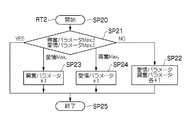
すなわち制御部10は、ステップSP6に進むと、この第1の感情パラメータ変更処理手順RT2をステップSP20において開始し、続くステップSP21において、「愛情レベル」及び「興奮レベル」のそれぞれについて、感情パラメータの値が最大値(この実施の形態では「8」)であるか否かを判断する。
That is, when proceeding to step SP6, the
そして制御部10は、このステップSP21において否定結果を得ると、ステップSP22に進んで、「愛情レベル」及び「興奮レベル」の各感情パラメータの値をそれぞれ1増加させる。そして制御部10は、この後ステップSP25に進んでこの第2の感情パラメータ変更処理手順RT2を終了し、さらにこの後感情生成表現処理手順RT1(図15)のステップSP13に進む。
If the
これに対して制御部10は、ステップSP21において「愛情レベル」の感情パラメータの値が最大値であると判断した場合には、ステップSP23に進んで「興奮レベル」の感情パラメータの値のみを1増加させる。そして制御部10は、この後ステップSP25に進んでこの第1の感情パラメータ変更処理手順RT2を終了し、さらにこの後感情生成表現処理手順RT1のステップSP13に進む。
On the other hand, when the
また制御部10は、ステップSP21において「興奮レベル」の感情パラメータの値が最大値であると判断した場合には、ステップSP24に進んで「愛情レベル」の感情パラメータの値のみを1増加させる。また制御部10は、この後ステップSP25に進んでこの第1の感情パラメータ変更処理手順RT2を終了し、さらにこの後感情生成表現処理手順RT1のステップSP13に進む。
If the
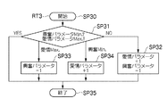
一方、制御部10は、ユーザがロボット玩具1の鼻スイッチ24を押圧操作することにより感情生成表現処理手順RT1のステップSP3において肯定結果を得たときには、ステップSP7に進んで、図17に示す第2の感情パラメータ変更処理手順RT3に従って感情の「愛情レベル」及び「興奮レベル」の各感情パラメータの値を変更する。
On the other hand, when the user presses the
すなわち制御部10は、ステップSP7に進むと、この第2の感情パラメータ変更処理手順RT3をステップSP30において開始し、続くステップSP31において、「愛情レベル」の感情パラメータの値が最大値であるか否か及び「興奮レベル」の感情パラメータの値が最小値(この実施の形態では「−8」)であるか否かを判断する。
That is, when proceeding to step SP7, the
そして制御部10は、このステップSP31において否定結果を得ると、ステップSP32に進んで、「愛情レベル」の感情パラメータの値を1増加させると共に「興奮レベル」の感情パラメータの値を1減少させる。また制御部10は、この後ステップSP35に進んでこの第2の感情パラメータ変更処理手順RT3を終了し、さらにこの後感情生成表現処理手順RT1(図15)のステップSP13に進む。
If the
これに対して制御部10は、ステップSP31において「愛情レベル」の感情パラメータの値が最大値であると判断した場合には、ステップSP33に進んで「興奮レベル」の感情パラメータの値のみを1減少させる。そして制御部10は、この後ステップSP35に進んでこの第2の感情パラメータ変更処理手順RT3を終了し、さらにこの後感情生成表現処理手順RT1のステップSP13に進む。
In contrast, if the
また制御部10は、ステップSP31において「興奮レベル」の感情パラメータの値が最小値であると判断した場合には、ステップSP34に進んで「愛情レベル」の感情パラメータの値のみを1増加させる。そして制御部10は、この後ステップSP35に進んでこの第2の感情パラメータ変更処理手順RT3を終了し、さらにこの後感情生成表現処理手順RT1のステップSP13に進む。
If the
他方、制御部10は、ユーザがロボット玩具1の尻尾スイッチ7を揺動操作することにより感情生成表現処理手順RT1のステップSP3において肯定結果を得たときには、ステップSP8に進んで、図18に示す第3の感情パラメータ変更処理手順RT4に従って感情の「愛情レベル」及び「興奮レベル」の各感情パラメータの値を変更する。
On the other hand, when the user obtains a positive result in step SP3 of the emotion generation expression processing procedure RT1 by swinging the
すなわち制御部10は、ステップSP8に進むと、この第3の感情パラメータ変更処理手順RT4をステップSP40において開始し、続くステップSP41において、「愛情レベル」の感情パラメータの値が最小値(この実施の形態では「−8」)であるか否か及び「興奮レベル」の感情パラメータの値が最大値であるか否かを判断する。
That is, when proceeding to step SP8, the
そして制御部10は、このステップSP41において否定結果を得ると、ステップSP42に進んで、「愛情レベル」の感情パラメータの値を1減少させると共に「興奮レベル」の感情パラメータの値を1増加させる。また制御部10は、この後ステップSP45に進んでこの第3の感情パラメータ変更処理手順RT4を終了し、さらにこの後感情生成表現処理手順RT1(図15)のステップSP13に進む。
If the
これに対して制御部10は、ステップSP41において「愛情レベル」の感情パラメータの値が最小値であると判断した場合には、ステップSP43に進んで「興奮レベル」の感情パラメータの値のみを1増加させる。そして制御部10は、この後ステップSP45に進んでこの第3の感情パラメータ変更処理手順RT4を終了し、さらにこの後感情生成表現処理手順RT1のステップSP13に進む。
In contrast, if the
また制御部10は、ステップSP41において「興奮レベル」の感情パラメータの値が最大値であると判断した場合には、ステップSP44に進んで「愛情レベル」の感情パラメータの値のみを1減少させる。そして制御部10は、この後ステップSP45に進んでこの第3の感情パラメータ変更処理手順RT4を終了し、さらにこの後感情生成表現処理手順RT1のステップSP13に進む。
If the
他方、制御部10は、「愛情レベル」及び「興奮レベル」の各感情パラメータの値をそれぞれ初期値に設定し、又は先に頭スイッチ23、鼻スイッチ24及び尻尾スイッチ7のうちのいずれかが押圧又は揺動操作されてから所定時間が経過することにより感情生成表現処理手順RT1のステップSP5において肯定結果を得たときには、ステップSP9に進んで、「愛情レベル」及び「興奮レベル」のそれぞれについて、感情パラメータの値が最小値であるか否かを判断する。
On the other hand, the
そして制御部10は、このステップSP9において否定結果を得ると、ステップSP10に進んで、「愛情レベル」及び「興奮レベル」の各感情パラメータの値をそれぞれ1増加させ、この後ステップSP13に進む。
If the
これに対して制御部10は、ステップSP9において「愛情レベル」の感情パラメータの値が最小値であると判断した場合には、ステップSP11に進んで「興奮レベル」の感情パラメータの値のみを1減少させ、この後ステップSP13に進む。
On the other hand, if the
また制御部10は、ステップSP9において「興奮レベル」の感情パラメータの値が最小値であると判断した場合には、ステップSP12に進んで「愛情レベル」の感情パラメータの値のみを1減少させ、この後ステップSP13に進む。
If the
そして制御部10は、上述のようにステップSP3〜ステップSP12においてユーザからの働きかけの有無やその内容に応じて更新した「興奮レベル」及び「愛情レベル」の各感情パラメータの値に基づいて、この後、ステップSP13〜ステップSP19において、そのときのロボット玩具1の感情及びその度合いをLED表示部21におけるLED21A〜21Gの発光パターンによって表現する。
And the
すなわち制御部10は、ステップSP13に進むと、かかる変更後の「興奮レベル」及び「愛情レベル」の感情パラメータの値をメモリ10B(図2)から読み出し、これら感情パラメータの値を判定する。そして制御部10は、「興奮レベル」及び「愛情レベル」の各感情パラメータが共に0又は正の値であったときにはステップSP14に進んで、図19に示す第1の感情表現処理手順RT5に従って、そのときのロボット玩具1の感情(「喜び」及び「大好き」)及びその度合いをLED表示部21におけるLED21A〜21Gの発光パターンとして表現する。
That is, when proceeding to step SP13, the
実際上、制御部10は、ステップSP14に進むと、この第1の感情表現処理手順RT5をステップSP50において開始し、続くステップSP51において、「興奮レベル」及び「愛情レベル」の各感情パラメータの値を判定する。そして制御部10は、「興奮レベル」及び「愛情レベル」の各感情パラメータの値が0から4までの範囲内である場合には、ステップSP52に進んで、橙色の光が1秒間で1周するようにLED表示部21における周囲の各LED21B〜21Gを順次橙色に点滅させ、「興奮レベル」及び「愛情レベル」の各感情パラメータの値がこれ以外の場合には、ステップSP53に進んで、橙色の光が0.5秒で1周するようにLED表示部21における周囲の各LED21B〜21Gを順次橙色に点滅させる。
In practice, when proceeding to step SP14, the
また制御部10は、ステップSP52又はステップSP53の処理を終了すると、ステップSP54に進んでこの第1の感情表現処理手順RT5を終了し、その後感情生成表現処理手順RT1のステップSP3に戻る。
In addition, when the processing of step SP52 or step SP53 is completed, the
一方、制御部10は、感情生成表現処理手順RT1のステップSP13の判定において、「興奮レベル」の感情パラメータの値が0又は正で、「愛情レベル」の感情パラメータが負であったときにはステップSP15に進んで、図20に示す第2の感情表現処理手順RT6に従って、そのときのロボット玩具1の感情(「怒り」及び「嫌い」)をLED表示部21におけるLED21A〜21Gの発光パターンとして表現する。
On the other hand, when the value of the emotion parameter of “excitement level” is 0 or positive and the emotion parameter of “love level” is negative in the determination in step SP13 of the emotion generation expression processing procedure RT1, the
すなわち制御部10は、ステップSP15に進むと、この第2の感情表現処理手順RT6をステップSP60において開始し、続くステップSP61において、「興奮レベル」及び「愛情レベル」の各感情パラメータの値を判定する。そして制御部10は、「興奮レベル」及び「愛情レベル」の各感情パラメータの値が0から4までの範囲内である場合には、ステップSP62に進んで、橙色の光が1秒間で1周するようにLED表示部21における周囲の各LED21B〜21Gを順次橙色に点滅させ、「興奮レベル」及び「愛情レベル」の各感情パラメータの値がこれ以外の場合には、ステップSP63に進んで、橙色の光が0.5秒で1周するようにLED表示部21における周囲の各LED21B〜21Gを順次橙色に点滅させる。
That is, when proceeding to step SP15, the
また制御部10は、ステップSP62又はステップSP63の処理を終了すると、ステップSP64に進んでこの第2の感情表現処理手順RT6を終了し、その後感情生成表現処理手順RT1のステップSP3に戻る。
Further, when the process of step SP62 or step SP63 is completed, the
他方、制御部10は、感情生成表現処理手順RT1のステップSP13の判定において、「興奮レベル」の感情パラメータの値が負で、「愛情レベル」の感情パラメータが0又は正であったときには、ステップSP16に進んで、図21に示す第3の感情表現処理手順RT7に従って、そのときのロボット玩具1の感情(「通常」及び「落ち着き」)をLED表示部21におけるLED21A〜21Gの発光パターンとして表現する。
On the other hand, when the value of the emotion parameter of “excitement level” is negative and the emotion parameter of “love level” is 0 or positive in the determination in step SP13 of the emotion generation expression processing procedure RT1, the
すなわち制御部10は、ステップSP16に進むと、この第3の感情表現処理手順RT3をステップSP70において開始し、続くステップSP71において、「興奮レベル」及び「愛情レベル」の各感情パラメータの値を判定する。そして制御部10は、「愛情レベル」の感情パラメータの値が−1から−4までの範囲内であり、かつ「興奮レベル」の感情パラメータの値が1から4までの範囲内にある場合には、ステップSP72に進んで、緑色の光が1秒間で1周するようにLED表示部21における周囲の各LED21B〜21Gを順次緑色に点滅させ、「興奮レベル」及び「愛情レベル」の各感情パラメータの値がこれ以外の場合には、ステップSP73に進んで、緑色の光が0.5秒で1周するようにLED表示部21における周囲の各LED21B〜21Gを順次緑色に点滅させる。
That is, when proceeding to step SP16, the
また制御部10は、ステップSP72又はステップSP73の処理を終了すると、ステップSP74に進んでこの第3の感情表現処理手順RT7を終了し、その後感情生成表現処理手順RT1のステップSP3に戻る。
In addition, when the process of step SP72 or step SP73 is completed, the
他方、制御部10は、感情生成表現処理手順RT1のステップSP13の判定において、「興奮レベル」及び「愛情レベル」の各感情パラメータの値が負であったときには、ステップSP17に進んで、「興奮レベル」及び「愛情レベル」の各感情パラメータの値を判定する。
On the other hand, when the value of each emotion parameter of “excitement level” and “love level” is negative in the determination in step SP13 of the emotion generation expression processing procedure RT1, the
そして制御部10は、「興奮レベル」及び「愛情レベル」の各感情パラメータの値が共に−1から−4までの範囲内である場合には、ステップSP18に進んで、LED表示部21における中央のLED21Aのみを1秒間に1回の周期で点滅させ、「興奮レベル」及び「愛情レベル」の各感情パラメータの値がこれ以外の場合には、ステップSP19に進んで、LED表示部21における中央のLED21Aのみを0.5秒間に1回の周期で点滅させる。また制御部10は、ステップSP18又はステップSP19の処理を終了すると、ステップSP3に戻る。
When the values of the emotion parameters of “excitement level” and “love level” are both in the range from −1 to −4, the
このようにして制御部10は、そのときのロボット玩具1の感情及びその度合いに応じた発光パターンでLED表示部21のLED21A〜21Gを点滅させる。
Thus, the
(3)まとめ
以上のように、本実施の形態のロボット玩具1は、「喜び」及び「大好き」の感情と、「通常」及び「落ち着き」の感情と、「怒り」及び「嫌い」の感情とを表現するときには、LED表示部21におけるLED21A〜21Gのうちの周囲のLED21B〜21Gのみを時計回り方向に1個ずつ点滅させ、「落ち込み」及び「寂しい」の感情を表現するときには、中央のLED21Aのみを青色に点滅させる。
(3) Summary As described above, the
そしてこのような表現方法によれば、例えば予め形状の定まったLEDを単に点滅させるだけの場合に比べて多様な発光パターンでロボット玩具1の感情を表現することができる一方で、複数のLEDをマトリクス状に配置する場合に比べて少ないLED数でLED表示部21を構築することができるため、ロボット玩具1を安価に構築しながら効果的に感情を表現することができる。
According to such an expression method, for example, it is possible to express the emotion of the
(4)他の実施形態
なお上記実施形態では、LED表示部21の中央のLED21A(第1の光源)として、緑色、赤色及び青色の3色を同時又は別個に発光し得るものを用い、他の周囲のLED21B〜12G(第2の光源)として、緑色及び赤色の2色を同時又は別個に発光し得るものを用いるようにしたが、中央のLED21Aの発光色の種類及びその数と、他の周囲のLED21B〜12Gの発光色の種類及びその数とについては、これ以外であってもよい。
(4) Other Embodiments In the above embodiment, the
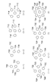
また上記実施形態では、中央のLED21Aから等距離にかつ相互に等間隔に位置するように残りの6つのLED21B〜21Gを配置するようにしたが、LED21A〜LED21Gの配置としては、これ以外の配置を適用することができる。例えば図22(A−1)及び(A−2)のように中央のLED70の周囲に3個のLED70B〜LED70Dを配置するようにしたり、図22(B−1)及び(B−2)のように中央のLED71Aの周囲に4個のLED71B〜71Eを配置したり、図22(C−1)及び(C−2)のように中央のLED72Aの周囲に5個のLED72B〜72Fを配置するようにしてもよい。また図22(D)のように中央のLED73Aの周囲に6個のLED73B〜73Gを配置する場合でも、この図のように配置するようにしてもよい。さらに図22(E)のように中央のLED73Aの周囲に8個のLED73B〜73Iを配置してもよく、これ以上のLEDを配置するようにしてもよい。このようにしても上記実施形態と同様の効果を得ることができる。
In the above embodiment, the remaining six
さらに上記実施形態では、感情パラメータを「興奮レベル」及び「愛情レベル」の2種類とするようにしたが、感情パラメータの数及び種類はこれ以外のものであってもよい。例えばLED21A〜21Gの発光色と同じ数だけ感情の種類を用意して、感情とLED21A〜21Gの発光色とを対応付けた発光パターンでLED21A〜21Gを点滅させるようにしてもよい。
Furthermore, in the above embodiment, the emotion parameters are two types of “excitement level” and “love level”, but the number and types of emotion parameters may be other than this. For example, the same number of types of emotions as the light emission colors of the
さらに上記実施形態では、LED表示部21の中央のLED21Aのみを点滅させたり、中央のLED21Aに対して周囲のLED21B〜21Gのみを時計回り方向に1個ずつ点滅させる発光パターンで各LED21A〜21Gを点滅させるようにしたが、発光パターンとしてはこれ以外の発光パターンであってもよい。例えば、中央のLED21Aに対して周囲のLED21B〜21Gのみを反時計回り方向に1個ずつ点滅させたり、又は中央のLED21Aに対して周囲のLED21B〜21Gのみを時計回り若しくは反時計回り方向に複数個ずつ点滅させるように、周囲のLED21B〜21Gを、隣り合うLED21B〜21Gに対して順次点灯と消灯を繰り返すように制御するようにしてもよい。
Furthermore, in the said embodiment, only LED21A of the center of the
さらに上記実施形態では、理解しやすくするため「興奮レベル」及び「愛情レベル」の各感情パラメータの値を−8〜8の範囲で変化させるようにしたが、この範囲はこれに限定されるものではなく、種々の範囲を適用することができる。またこれに伴って、感情生成表現処理手順RT1の内容も適宜変更することができる。例えば、実際のコンピュータ処理では、−8〜8の範囲の数が0〜15(16進法での0〜F)の範囲の数として処理されるため、例えば感情生成表現処理手順RT1のステップSP13について上述したような感情パラメータが正又は負のいずれであるかといった判定は行われず、ステップSP14(又はステップSP15〜ステップSP17)と合わせて感情パラメータの値が0〜3,4〜7,8〜B,C〜Fの何れの範囲に含まれるかを判定して、その範囲に対応付けられた色及び発光パターンでLED21A〜21Gを発光させるようにしても良い。要は、感情パラメータの値の組み合わせに対応した発光パターンでLED21A〜21Gを発光させるのであれば、その手法としては種々の手法を適用することができる。
Furthermore, in the above embodiment, the emotion parameter values of “excitement level” and “love level” are changed in the range of −8 to 8 for easy understanding, but this range is limited to this. Instead, various ranges can be applied. Along with this, the contents of the emotion generation expression processing procedure RT1 can be changed as appropriate. For example, in actual computer processing, since the number in the range of -8 to 8 is processed as the number in the range of 0 to 15 (0 to F in hexadecimal notation), for example, step SP13 of the emotion generation expression processing procedure RT1 The determination as to whether the emotion parameter is positive or negative is not performed, and the value of the emotion parameter is 0-3, 4-7, 8- in combination with step SP14 (or step SP15-step SP17). It may be determined in which range of B and C to F, and the
本発明は、種々のロボット玩具に広く適用することができる。 The present invention can be widely applied to various robot toys.
1……ロボット玩具、3……頭部、7……尻尾スイッチ、10……制御部、21……LED表示部、21A〜21G、70A〜70D、71A〜71E、72A〜72F、73A〜73G……LED、23……頭スイッチ、24……鼻スイッチ。
DESCRIPTION OF
Claims (8)
前記第1の光源の周囲に配置された5つ以上の第2の光源と、
感情を定義する少なくとも2種類の感情パラメータを記憶するメモリと、
外部からの操作入力に基づいて前記感情パラメータの値を増減させる制御手段と
を備え、
前記制御手段は、
各前記感情パラメータの値の組み合せに対応した発光パターンで前記第1及び又は前記第2の光源を発光させる
ことを特徴とするロボット玩具。 A first light source capable of emitting at least two colors of light simultaneously or individually;
Five or more second light sources disposed around the first light source;
A memory for storing at least two types of emotion parameters that define emotions;
Control means for increasing or decreasing the value of the emotion parameter based on an operation input from the outside,
The control means includes
The robot toy characterized in that the first and / or the second light source emit light with a light emission pattern corresponding to a combination of values of the emotion parameters.
少なくとも一方の各前記感情パラメータの値によって決定される前記感情の度合いに応じて、当該度合いが大きいほど速い周期で前記第1及び又は第2の光源を点滅させる
ことを特徴とする請求項1に記載のロボット玩具。 The control means includes
The first and / or second light source is caused to blink at a faster cycle as the degree increases according to the degree of the emotion determined by the value of at least one of the emotion parameters. The robot toy described.
各前記感情パラメータの値の組み合わせによって決定される前記感情の種類に応じた色で前記第1及び又は前記第2の光源を点滅させる
ことを特徴とする請求項1に記載のロボット玩具。 The control means includes
2. The robot toy according to claim 1, wherein the first and / or the second light source blinks in a color corresponding to the type of emotion determined by a combination of values of the emotion parameters.
前記第1の光源を中心に等間隔に配置され、
前記制御手段によって、隣り合う前記第2の光源に対して順次点灯と消灯を繰り返すように制御される
ことを特徴とする請求項2又は請求項3に記載のロボット玩具。 Each of the second light sources is
Arranged at regular intervals around the first light source;
The robot toy according to claim 2 or 3, wherein the controller is controlled to sequentially turn on and off the adjacent second light sources.
ことを特徴とする請求項1に記載のロボット玩具。 2. The robot toy according to claim 1, wherein the first light source can emit more colors than the number of colors that the second light source can emit separately.
各前記感情パラメータの値の組み合わせによって決定される前記感情の種類が予め定められた所定種類に該当するときには、前記第1の光源を、前記第2の光源が発光できない所定色で発光させる
ことを特徴とする請求項1又は請求項5に記載のロボット玩具。 The control means includes
When the emotion type determined by the combination of the emotion parameter values corresponds to a predetermined type, the first light source emits light in a predetermined color that the second light source cannot emit. The robot toy according to claim 1 or 5, wherein the robot toy is characterized.
を備えることを特徴とする請求項1に記載のロボット玩具。 The robot toy according to claim 1, further comprising a translucent cover arranged to cover the first and second light sources.
前記制御手段は、
前記操作入力スイッチのそれぞれの操作入力に対応して、前記感情パラメータの値をそれぞれ増加させ、所定時間の操作入力がない場合に、前記感情パラメータの値を減少させる
ことを特徴とする請求項1に記載のロボット玩具。 The robot toy has two or more operation input switches,
The control means includes
The value of the emotion parameter is increased corresponding to each operation input of the operation input switch, and the value of the emotion parameter is decreased when there is no operation input for a predetermined time. The robot toy described in 1.
Priority Applications (3)
| Application Number | Priority Date | Filing Date | Title |
|---|---|---|---|
| JP2005010771A JP2006198017A (en) | 2005-01-18 | 2005-01-18 | Robot toy |
| PCT/JP2006/300617 WO2006077868A1 (en) | 2005-01-18 | 2006-01-18 | Robot toy |
| US11/775,133 US20070270074A1 (en) | 2005-01-18 | 2007-07-09 | Robot Toy |
Applications Claiming Priority (1)
| Application Number | Priority Date | Filing Date | Title |
|---|---|---|---|
| JP2005010771A JP2006198017A (en) | 2005-01-18 | 2005-01-18 | Robot toy |
Publications (2)
| Publication Number | Publication Date |
|---|---|
| JP2006198017A true JP2006198017A (en) | 2006-08-03 |
| JP2006198017A5 JP2006198017A5 (en) | 2007-12-20 |
Family
ID=36692257
Family Applications (1)
| Application Number | Title | Priority Date | Filing Date |
|---|---|---|---|
| JP2005010771A Pending JP2006198017A (en) | 2005-01-18 | 2005-01-18 | Robot toy |
Country Status (3)
| Country | Link |
|---|---|
| US (1) | US20070270074A1 (en) |
| JP (1) | JP2006198017A (en) |
| WO (1) | WO2006077868A1 (en) |
Cited By (5)
| Publication number | Priority date | Publication date | Assignee | Title |
|---|---|---|---|---|
| US8062089B2 (en) | 2006-10-02 | 2011-11-22 | Mattel, Inc. | Electronic playset |
| US8292689B2 (en) | 2006-10-02 | 2012-10-23 | Mattel, Inc. | Electronic playset |
| US8515092B2 (en) | 2009-12-18 | 2013-08-20 | Mattel, Inc. | Interactive toy for audio output |
| WO2020009098A1 (en) * | 2018-07-02 | 2020-01-09 | Groove X株式会社 | Robot |
| CN110815234A (en) * | 2018-08-07 | 2020-02-21 | 圈乐斯株式会社 | Control method and control server of interactive robot |
Families Citing this family (17)
| Publication number | Priority date | Publication date | Assignee | Title |
|---|---|---|---|---|
| TWM285388U (en) * | 2005-10-05 | 2006-01-11 | Wen-Bin Shiu | Pet toy combining with MP3 player |
| CN101406756A (en) * | 2007-10-12 | 2009-04-15 | 鹏智科技(深圳)有限公司 | Electronic toy for expressing emotion and method for expressing emotion, and luminous unit control device |
| CN101411946B (en) * | 2007-10-19 | 2012-03-28 | 鸿富锦精密工业(深圳)有限公司 | Toy dinosaur |
| US20100305448A1 (en) * | 2009-05-26 | 2010-12-02 | Anne Cecile Dagonneau | Apparatus and method for indicating ultrasound probe orientation and activation status |
| US8438233B2 (en) * | 2011-03-23 | 2013-05-07 | Color Labs, Inc. | Storage and distribution of content for a user device group |
| US20120320077A1 (en) * | 2011-06-17 | 2012-12-20 | Microsoft Corporation | Communicating status and expression |
| US9656392B2 (en) * | 2011-09-20 | 2017-05-23 | Disney Enterprises, Inc. | System for controlling robotic characters to enhance photographic results |
| US8473550B2 (en) | 2011-09-21 | 2013-06-25 | Color Labs, Inc. | Content sharing using notification within a social networking environment |
| US10433767B2 (en) * | 2011-12-21 | 2019-10-08 | Koninklijke Philips N.V. | Peel and stick CPR assistance device |
| CN102980103A (en) * | 2012-11-27 | 2013-03-20 | 华南理工大学 | Machine vision LED (light emitting diode) illumination source |
| US20160025326A1 (en) * | 2014-07-28 | 2016-01-28 | Sergei GONCHAR | Sparkly childrens products |
| CN105676740A (en) * | 2016-03-01 | 2016-06-15 | 深圳前海勇艺达机器人有限公司 | Method and apparatus enabling robot to have illumination function |
| US10290181B2 (en) | 2016-05-13 | 2019-05-14 | Universal Entertainment Corporation | Attendant device and gaming machine |
| JP6572943B2 (en) * | 2017-06-23 | 2019-09-11 | カシオ計算機株式会社 | Robot, robot control method and program |
| JP6936081B2 (en) * | 2017-08-30 | 2021-09-15 | パナソニック株式会社 | robot |
| JP1622874S (en) * | 2017-12-29 | 2019-01-28 | robot | |
| KR102415997B1 (en) * | 2020-11-05 | 2022-07-05 | (주)로보티즈 | Companion robot |
Citations (3)
| Publication number | Priority date | Publication date | Assignee | Title |
|---|---|---|---|---|
| JP3277500B2 (en) * | 1999-05-10 | 2002-04-22 | ソニー株式会社 | Robot device |
| JP2003060745A (en) * | 2001-08-22 | 2003-02-28 | Sony Corp | Device and method for transmitting information and monitoring device |
| JP2003071765A (en) * | 2001-09-04 | 2003-03-12 | Sony Corp | Robot device and input method therefor |
Family Cites Families (20)
| Publication number | Priority date | Publication date | Assignee | Title |
|---|---|---|---|---|
| US6337552B1 (en) * | 1999-01-20 | 2002-01-08 | Sony Corporation | Robot apparatus |
| US4556932A (en) * | 1983-03-28 | 1985-12-03 | Lehrer Bradley D | Lighted novelty item |
| JPS60128699U (en) * | 1984-02-07 | 1985-08-29 | 株式会社トミー | radio controlled toy |
| US5141464A (en) * | 1991-01-23 | 1992-08-25 | Mattel, Inc. | Touch responsive animated toy figure |
| US5402702A (en) * | 1992-07-14 | 1995-04-04 | Jalco Co., Ltd. | Trigger circuit unit for operating light emitting members such as leds or motors for use in personal ornament or toy in synchronization with music |
| US5461188A (en) * | 1994-03-07 | 1995-10-24 | Drago; Marcello S. | Synthesized music, sound and light system |
| US5668333A (en) * | 1996-06-05 | 1997-09-16 | Hasbro, Inc. | Musical rainbow toy |
| WO2000068879A1 (en) * | 1999-05-10 | 2000-11-16 | Sony Corporation | Robot device, its control method, and recorded medium |
| JP2001191284A (en) * | 1999-10-25 | 2001-07-17 | Sony Corp | Robot device and its learning method |
| USD457203S1 (en) * | 1999-11-02 | 2002-05-14 | Sega Toys, Ltd. | Robotic dog |
| USD448433S1 (en) * | 1999-11-02 | 2001-09-25 | Sega Toys Ltd. | Robotic dog |
| JP2001191281A (en) * | 1999-12-29 | 2001-07-17 | Sony Corp | Editing device, editing method, and storage medium |
| US6672934B2 (en) * | 2000-02-04 | 2004-01-06 | Trendmasters, Inc. | Amusement device |
| US6462498B1 (en) * | 2000-05-09 | 2002-10-08 | Andrew J. Filo | Self-stabilizing walking apparatus that is capable of being reprogrammed or puppeteered |
| JP2002018146A (en) * | 2000-07-04 | 2002-01-22 | Tomy Co Ltd | Interactive toy, reaction behavior generator and reaction behavior pattern generation method |
| JP2002127059A (en) * | 2000-10-20 | 2002-05-08 | Sony Corp | Action control device and method, pet robot and control method, robot control system and recording medium |
| JP2002154081A (en) * | 2000-11-16 | 2002-05-28 | Nec Access Technica Ltd | Robot, its facial expression method and detecting method for step difference and lifting-up state |
| US6507773B2 (en) * | 2001-06-14 | 2003-01-14 | Sharper Image Corporation | Multi-functional robot with remote and video system |
| JP2004237392A (en) * | 2003-02-05 | 2004-08-26 | Sony Corp | Robotic device and expression method of robotic device |
| US7374482B2 (en) * | 2003-08-12 | 2008-05-20 | Ghaly Nabil N | Interactive slot machine |
-
2005
- 2005-01-18 JP JP2005010771A patent/JP2006198017A/en active Pending
-
2006
- 2006-01-18 WO PCT/JP2006/300617 patent/WO2006077868A1/en not_active Application Discontinuation
-
2007
- 2007-07-09 US US11/775,133 patent/US20070270074A1/en not_active Abandoned
Patent Citations (3)
| Publication number | Priority date | Publication date | Assignee | Title |
|---|---|---|---|---|
| JP3277500B2 (en) * | 1999-05-10 | 2002-04-22 | ソニー株式会社 | Robot device |
| JP2003060745A (en) * | 2001-08-22 | 2003-02-28 | Sony Corp | Device and method for transmitting information and monitoring device |
| JP2003071765A (en) * | 2001-09-04 | 2003-03-12 | Sony Corp | Robot device and input method therefor |
Cited By (6)
| Publication number | Priority date | Publication date | Assignee | Title |
|---|---|---|---|---|
| US8062089B2 (en) | 2006-10-02 | 2011-11-22 | Mattel, Inc. | Electronic playset |
| US8292689B2 (en) | 2006-10-02 | 2012-10-23 | Mattel, Inc. | Electronic playset |
| US8515092B2 (en) | 2009-12-18 | 2013-08-20 | Mattel, Inc. | Interactive toy for audio output |
| WO2020009098A1 (en) * | 2018-07-02 | 2020-01-09 | Groove X株式会社 | Robot |
| JPWO2020009098A1 (en) * | 2018-07-02 | 2021-08-05 | Groove X株式会社 | robot |
| CN110815234A (en) * | 2018-08-07 | 2020-02-21 | 圈乐斯株式会社 | Control method and control server of interactive robot |
Also Published As
| Publication number | Publication date |
|---|---|
| US20070270074A1 (en) | 2007-11-22 |
| WO2006077868A1 (en) | 2006-07-27 |
Similar Documents
| Publication | Publication Date | Title |
|---|---|---|
| JP2006198017A (en) | Robot toy | |
| JP7226872B2 (en) | Light Emitting Diode Switch Elements and Arrays | |
| US6544098B1 (en) | Interactive toy | |
| JP2006198017A5 (en) | ||
| US7442107B1 (en) | Electronic toy, control method thereof, and storage medium | |
| US20170333801A1 (en) | Assembly with toy character in housing | |
| NO324232B1 (en) | Remote controlled play | |
| MX2008013964A (en) | Electronic toy with alterable features. | |
| US20110195632A1 (en) | Toy | |
| US20150093958A1 (en) | System for Controlled Distribution of Light in Toy Characters | |
| JP2018086125A (en) | Performance output toy, and item for performance output toy | |
| CN110536729B (en) | Interactive modular construction element and modular construction system with interactive modular construction element | |
| US6746299B1 (en) | Infant-operable remote controlled entertainment and education device and system | |
| JP4757979B2 (en) | Electronic toy | |
| US20040150993A1 (en) | Illuminated sound and image display for an infant | |
| JP2013090765A (en) | Mechatronized wood building block for intellectual training | |
| JP3121098U (en) | Accessories toy | |
| KR20010091876A (en) | Electronic toy and method of controlling the same and memory media | |
| JP7217694B2 (en) | Production output toy and production output toy set | |
| TWM501119U (en) | Glove with music recognition | |
| JP7313397B2 (en) | Production output toys and items for production output toys | |
| JP3182303U (en) | Luminous toys | |
| JP2005349077A (en) | Sound generating toy | |
| JP2020113466A (en) | Illumination device | |
| TWM369522U (en) | Game apparatus with music memorizing |
Legal Events
| Date | Code | Title | Description |
|---|---|---|---|
| A521 | Written amendment |
Free format text: JAPANESE INTERMEDIATE CODE: A523 Effective date: 20061128 |
|
| A521 | Written amendment |
Free format text: JAPANESE INTERMEDIATE CODE: A523 Effective date: 20071105 |
|
| A621 | Written request for application examination |
Free format text: JAPANESE INTERMEDIATE CODE: A621 Effective date: 20071105 |
|
| RD04 | Notification of resignation of power of attorney |
Free format text: JAPANESE INTERMEDIATE CODE: A7424 Effective date: 20101019 |
|
| A131 | Notification of reasons for refusal |
Free format text: JAPANESE INTERMEDIATE CODE: A131 Effective date: 20101117 |
|
| A711 | Notification of change in applicant |
Free format text: JAPANESE INTERMEDIATE CODE: A711 Effective date: 20110111 |
|
| A521 | Written amendment |
Free format text: JAPANESE INTERMEDIATE CODE: A523 Effective date: 20110114 |
|
| A521 | Written amendment |
Free format text: JAPANESE INTERMEDIATE CODE: A821 Effective date: 20110111 |
|
| A02 | Decision of refusal |
Free format text: JAPANESE INTERMEDIATE CODE: A02 Effective date: 20110401 |