JP2005296512A - Self-traveling cleaner - Google Patents
Self-traveling cleaner Download PDFInfo
- Publication number
- JP2005296512A JP2005296512A JP2004120607A JP2004120607A JP2005296512A JP 2005296512 A JP2005296512 A JP 2005296512A JP 2004120607 A JP2004120607 A JP 2004120607A JP 2004120607 A JP2004120607 A JP 2004120607A JP 2005296512 A JP2005296512 A JP 2005296512A
- Authority
- JP
- Japan
- Prior art keywords
- human body
- self
- emotion
- suction
- main body
- Prior art date
- Legal status (The legal status is an assumption and is not a legal conclusion. Google has not performed a legal analysis and makes no representation as to the accuracy of the status listed.)
- Withdrawn
Links
- 230000008451 emotion Effects 0.000 claims description 47
- 238000004140 cleaning Methods 0.000 claims description 37
- 230000007246 mechanism Effects 0.000 claims description 33
- 230000008859 change Effects 0.000 claims description 18
- 230000004044 response Effects 0.000 claims description 10
- 238000001514 detection method Methods 0.000 description 35
- 238000003384 imaging method Methods 0.000 description 17
- 230000001133 acceleration Effects 0.000 description 12
- 238000000034 method Methods 0.000 description 12
- 239000000428 dust Substances 0.000 description 10
- 238000012544 monitoring process Methods 0.000 description 9
- 230000008569 process Effects 0.000 description 8
- 238000005286 illumination Methods 0.000 description 7
- 238000010586 diagram Methods 0.000 description 6
- 239000004973 liquid crystal related substance Substances 0.000 description 5
- 230000005856 abnormality Effects 0.000 description 4
- 230000003434 inspiratory effect Effects 0.000 description 4
- 238000004891 communication Methods 0.000 description 3
- 238000005259 measurement Methods 0.000 description 3
- 230000003287 optical effect Effects 0.000 description 3
- 230000008901 benefit Effects 0.000 description 2
- 230000002996 emotional effect Effects 0.000 description 2
- 238000012545 processing Methods 0.000 description 2
- 241000272525 Anas platyrhynchos Species 0.000 description 1
- 238000006243 chemical reaction Methods 0.000 description 1
- 230000007423 decrease Effects 0.000 description 1
- 230000003247 decreasing effect Effects 0.000 description 1
- 230000000694 effects Effects 0.000 description 1
- 238000002474 experimental method Methods 0.000 description 1
- 230000006698 induction Effects 0.000 description 1
- 238000013507 mapping Methods 0.000 description 1
- 238000005096 rolling process Methods 0.000 description 1
Images
Classifications
-
- G—PHYSICS
- G05—CONTROLLING; REGULATING
- G05D—SYSTEMS FOR CONTROLLING OR REGULATING NON-ELECTRIC VARIABLES
- G05D1/00—Control of position, course, altitude or attitude of land, water, air or space vehicles, e.g. using automatic pilots
- G05D1/02—Control of position or course in two dimensions
- G05D1/021—Control of position or course in two dimensions specially adapted to land vehicles
- G05D1/0259—Control of position or course in two dimensions specially adapted to land vehicles using magnetic or electromagnetic means
-
- G—PHYSICS
- G05—CONTROLLING; REGULATING
- G05D—SYSTEMS FOR CONTROLLING OR REGULATING NON-ELECTRIC VARIABLES
- G05D1/00—Control of position, course, altitude or attitude of land, water, air or space vehicles, e.g. using automatic pilots
- G05D1/02—Control of position or course in two dimensions
- G05D1/021—Control of position or course in two dimensions specially adapted to land vehicles
- G05D1/0231—Control of position or course in two dimensions specially adapted to land vehicles using optical position detecting means
- G05D1/0246—Control of position or course in two dimensions specially adapted to land vehicles using optical position detecting means using a video camera in combination with image processing means
-
- G—PHYSICS
- G05—CONTROLLING; REGULATING
- G05D—SYSTEMS FOR CONTROLLING OR REGULATING NON-ELECTRIC VARIABLES
- G05D1/00—Control of position, course, altitude or attitude of land, water, air or space vehicles, e.g. using automatic pilots
- G05D1/02—Control of position or course in two dimensions
- G05D1/021—Control of position or course in two dimensions specially adapted to land vehicles
- G05D1/0268—Control of position or course in two dimensions specially adapted to land vehicles using internal positioning means
- G05D1/0272—Control of position or course in two dimensions specially adapted to land vehicles using internal positioning means comprising means for registering the travel distance, e.g. revolutions of wheels
-
- G—PHYSICS
- G05—CONTROLLING; REGULATING
- G05D—SYSTEMS FOR CONTROLLING OR REGULATING NON-ELECTRIC VARIABLES
- G05D1/00—Control of position, course, altitude or attitude of land, water, air or space vehicles, e.g. using automatic pilots
- G05D1/02—Control of position or course in two dimensions
- G05D1/021—Control of position or course in two dimensions specially adapted to land vehicles
- G05D1/0231—Control of position or course in two dimensions specially adapted to land vehicles using optical position detecting means
- G05D1/0242—Control of position or course in two dimensions specially adapted to land vehicles using optical position detecting means using non-visible light signals, e.g. IR or UV signals
-
- G—PHYSICS
- G05—CONTROLLING; REGULATING
- G05D—SYSTEMS FOR CONTROLLING OR REGULATING NON-ELECTRIC VARIABLES
- G05D1/00—Control of position, course, altitude or attitude of land, water, air or space vehicles, e.g. using automatic pilots
- G05D1/02—Control of position or course in two dimensions
- G05D1/021—Control of position or course in two dimensions specially adapted to land vehicles
- G05D1/0268—Control of position or course in two dimensions specially adapted to land vehicles using internal positioning means
- G05D1/0274—Control of position or course in two dimensions specially adapted to land vehicles using internal positioning means using mapping information stored in a memory device
Landscapes
- Engineering & Computer Science (AREA)
- Physics & Mathematics (AREA)
- General Physics & Mathematics (AREA)
- Aviation & Aerospace Engineering (AREA)
- Radar, Positioning & Navigation (AREA)
- Remote Sensing (AREA)
- Automation & Control Theory (AREA)
- Electromagnetism (AREA)
- Computer Vision & Pattern Recognition (AREA)
- Multimedia (AREA)
- Control Of Position, Course, Altitude, Or Attitude Of Moving Bodies (AREA)
- Electric Vacuum Cleaner (AREA)
- Electric Suction Cleaners (AREA)
Abstract
Description
本発明は、掃除機構を備えた本体と、操舵及び駆動が可能な駆動機構とを備える自走式掃除機に関するものである。 The present invention relates to a self-propelled cleaner provided with a main body provided with a cleaning mechanism and a drive mechanism capable of steering and driving.
従来、自走式のロボットとして、特許文献1に示すものが知られている。同ロボットにおいては、ロボットに備えられたライトの光の色や強さや点滅速度、音や声の強さや再生速度やトーンを制御することが可能である。
そして、これらを適宜制御することにより、擬似的に感情を表現可能となっている。
一方、自走式の掃除機として、特許文献2に示すものでは、超音波センサを本体の側面に配置して自律して行動するものが開示されている。
Then, by appropriately controlling these, it is possible to express emotions in a pseudo manner.
On the other hand, as a self-propelled cleaner, the one shown in
上述した従来の自走式掃除機において、前者のものは、光や音で感情を表現しようとしているが、一般的であって趣向性に欠ける。後者のものは、あくまでも掃除機であって、感情などを表現するようなものではなく、その機能もない。
本発明は、上記課題に鑑みてなされたもので、個性的なロボットであって掃除も可能な自走式掃除機を提供することを目的とする。
In the above-described conventional self-propelled cleaner, the former one is intended to express emotions with light or sound, but is general and lacks preference. The latter is only a vacuum cleaner, does not express emotions, and has no function.
The present invention has been made in view of the above problems, and an object thereof is to provide a self-propelled cleaner that is a unique robot and can be cleaned.
本発明は、上記課題に鑑みてなされたもので、吸引モータにて駆動される吸引式の掃除機構を備えた本体と、操舵及び駆動が可能な駆動機構とを備える自走式掃除機であって、人体を検知する人体センサを有し、人体を検知したときに表現する感情を選択する感情選択手段と、選択された感情に対応して上記吸引モータの回転を制御して吸気音に変化を生じさせる吸気音制御手段と、上記選択された感情に対応して上記駆動機構を制御して動作を制御する動作制御手段とを具備する構成としてある。 The present invention has been made in view of the above problems, and is a self-propelled cleaner including a main body including a suction-type cleaning mechanism driven by a suction motor and a drive mechanism capable of steering and driving. And a human body sensor for detecting a human body, an emotion selection means for selecting an emotion to be expressed when the human body is detected, and a change to an intake sound by controlling the rotation of the suction motor in response to the selected emotion Inhalation sound control means for generating the sound and operation control means for controlling the operation by controlling the drive mechanism in response to the selected emotion.
上記のように構成した場合、掃除機構は吸引モータを有し、同吸引モータにて吸引式の掃除を実行可能であるとともに、駆動機構により操舵及び走行が可能である。また、感情選択手段は、人体センサを備えて人体を検知することが可能であり、人体を検知したときに表現する感情を選択する。感情を選択したら、吸気音制御手段は選択された感情に対応して上記吸引モータの回転を制御して吸気音に変化を生じさせ、また、動作制御手段は上記選択された感情に対応して上記駆動機構を制御して動作を制御する。 When configured as described above, the cleaning mechanism has a suction motor, and the suction motor can perform suction cleaning and can be steered and driven by the drive mechanism. The emotion selection means is equipped with a human body sensor and can detect a human body, and selects an emotion to be expressed when the human body is detected. When the emotion is selected, the intake sound control means controls the rotation of the suction motor in response to the selected emotion to cause a change in the intake sound, and the operation control means corresponds to the selected emotion. The drive mechanism is controlled to control the operation.
このように自走式の掃除が可能であることを前提としつつも、吸引モータの回転を制御することで吸気音に変化を生じさせて感情を表現できる。また、感情表現は吸気音にとどまらず、動作でも実現する。 While assuming that self-propelled cleaning is possible in this way, it is possible to express emotions by changing the intake sound by controlling the rotation of the suction motor. In addition, emotional expression is realized not only by inspiratory sound but also by movement.
吸気音に変化を生じさせる好適な一例として、請求項3にかかる発明では、上記吸引モータによる吸引及び排気経路に装着して吸気音を変化させるアダプタを有する構成としてある。 As a preferred example of causing a change in the intake sound, the invention according to claim 3 is configured to include an adapter that is attached to the suction and exhaust paths by the suction motor and changes the intake sound.
上記のように構成した場合、感情を表現させる場合には吸引及び排気経路にアダプタを装着する。これにより、通常の吸気音とは大きく音を変化さえることができ、これを前提とした感情表現が豊かとなる。 When comprised as mentioned above, when expressing an emotion, an adapter is attached to the suction and exhaust routes. As a result, the sound can be changed greatly from the normal intake sound, and the emotional expression based on this can be enriched.
掃除機構は、吸引式を基本としつつも他のタイプも併用可能であり、その一例として請求項4にかかる発明では、上記掃除機構は、本体の側方から外部に突き出るサイドブラシと、当該サイドブラシを駆動するサイドブラシモータを有し、上記選択された感情に対応して同サイドブラシモータの駆動を制御する構成としてある。 While the cleaning mechanism is based on a suction type, other types can be used together. As an example, in the invention according to claim 4, the cleaning mechanism includes a side brush projecting from the side of the main body and the side brush. A side brush motor for driving the brush is provided, and the driving of the side brush motor is controlled in accordance with the selected emotion.
上記のように構成した場合、本体の側方からはサイドブラシが外部に突き出ており、外部から視認可能である。そこで、当該サイドブラシを駆動するサイドブラシモータの駆動を制御することでサイドブラシの動作によっても感情表現が可能となる。 When comprised as mentioned above, the side brush protrudes outside from the side of the main body and is visible from the outside. Thus, by controlling the driving of the side brush motor that drives the side brush, it is possible to express emotions even by the operation of the side brush.
動作には各種のものを採用可能であり、その一例として、請求項5にかかる発明では、上記動作制御手段は、人体に近寄る動作と、人体から離れていく動作と、人体の周りを回転させる動作を上記駆動機構で実現可能な構成としてある。 For example, in the invention according to claim 5, the motion control means rotates the motion around the human body, the motion approaching the human body, the motion moving away from the human body, and the like. The operation can be realized by the drive mechanism.
上記のように構成した場合、人体を検知して近づけば喜び一般を表せるし、離れれば悲しみや怒りを表せるし、人体の周りを回転すればさらなる喜びなどを表せる。 When configured as described above, it is possible to express joy in general by detecting and approaching the human body, to express sadness and anger if it moves away, and to express further joy etc. by rotating around the human body.
操舵及び駆動が可能な駆動機構については、各種の構成が可能である。駆動機構は、車輪のみならず、無端ベルトを駆動する構成で実現しても良い。むろん、これ以外にも、4輪、6輪など、各種の構成で駆動機構を実現可能である。 Various configurations are possible for the drive mechanism capable of steering and driving. The drive mechanism may be realized by a configuration that drives not only the wheel but also an endless belt. Of course, besides this, the drive mechanism can be realized with various configurations such as four wheels and six wheels.
そして、以上のような構成を踏まえたより具体的な構成の一例として、請求項1にかかる発明は、吸引モータにて駆動される吸引式の掃除機構を備えた本体と、同本体における左右に配置されて個別に回転を制御可能で操舵と駆動を実現する駆動輪を有する駆動機構とを備える自走式掃除機であって、上記掃除機構は、本体の側方から外部に突き出るサイドブラシと、当該サイドブラシを駆動するサイドブラシモータを有するとともに、上記吸引モータによる吸引及び排気経路に装着して吸気音を変化させるアダプタを有し、かつ、人体を検知する人体センサを有し、表現する感情を選択する感情選択手段と、選択された感情に対応して上記吸引モータの回転を制御して吸気音に変化を生じさせる吸気音制御手段と、上記選択された感情に対応して、人体に近寄る動作と、人体から離れていく動作と、人体の周りを回転させる動作を上記駆動機構を制御して実現させる動作制御手段とを具備する構成としてある。 And as an example of a more specific configuration based on the configuration as described above, the invention according to claim 1 includes a main body provided with a suction-type cleaning mechanism driven by a suction motor, and arranged on the left and right of the main body. A self-propelled cleaner having a drive mechanism having a drive wheel capable of individually controlling rotation and realizing steering and driving, wherein the cleaning mechanism includes a side brush protruding outward from the side of the main body, An emotion that has a side brush motor that drives the side brush, an adapter that is attached to the suction and exhaust paths by the suction motor to change the intake sound, and has a human body sensor that detects the human body. An emotion selection means for selecting the intake sound, a suction sound control means for controlling the rotation of the suction motor in response to the selected emotion to cause a change in the intake sound, and a response to the selected emotion. To, it is constituted comprising an act of KEEP to the human body, the operation moves away from the body, and an operation control means for the operation of rotating around the human body is achieved by controlling the drive mechanism.
上記のような構成とすることにより、本来の自走式の掃除機構を前提としつつも、人体を検知して感情を選択し、吸気音やサイドブラシ、及び本体の動作により、個性的な感情表現が可能なロボットを実現できる。 By adopting the above-mentioned configuration, while assuming the original self-propelled cleaning mechanism, the human body is detected and emotions are selected. A robot capable of expression can be realized.
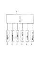
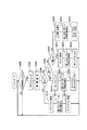
図1は、本発明にかかる自走式掃除機の概略構成をブロック図により示している。
同図に示すように、各ユニットを制御する制御ユニット10と、周囲に人間がいるか否かを検知する人体感知ユニット20と、周囲の障害物を検知するための障害物監視ユニット30と、移動を実現する走行系ユニット40と、掃除を行うためのクリーナ系ユニット50と、所定範囲を撮影するカメラ系ユニット60と、無線でLANに接続するための無線LANユニット70とから構成されている。なお、本体BDは薄型の略円筒形状をなしている。
FIG. 1 is a block diagram showing a schematic configuration of a self-propelled cleaner according to the present invention.
As shown in the figure, a
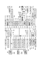
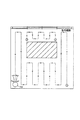
図2は、各ユニットを具体的に実現する電気系の構成をブロック図により示している。 制御ユニット10として、CPU11と、ROM13と、RAM12がバス14を介して接続されている。CPU11は、ROM13に記録されている制御用プログラムおよび各種パラメータテーブルに従い、RAM12をワークエリアとして使用して各種の制御を実行する。上記制御用プログラムの内容については後述する。
FIG. 2 is a block diagram showing the configuration of an electric system that specifically realizes each unit. As the
また、バス14には操作パネルユニット15が備えられ、同操作パネルユニット15には、各種の操作用スイッチ15aと、液晶表示パネル15bと、表示用LED15cが備えられている。液晶表示パネルは多階調表示が可能なモノクロ液晶パネルを使用しているが、カラー液晶パネルなどを使用することも可能である。
The
本自走式掃除機はバッテリー17を有しており、CPU11はバッテリ監視回路16を介してバッテリー17の残量をモニター可能となっている。なお、同バッテリー17は誘導コイル18aを介して非接触で供給される電力を用いて充電する充電回路18を備えている。バッテリー監視回路16は主にバッテリー17の電圧を監視して残量を検知する。
This self-propelled cleaner has a battery 17, and the CPU 11 can monitor the remaining amount of the battery 17 via the battery monitoring circuit 16. The battery 17 includes a
人体感知ユニット20として、四つの人体センサ21(21fr,21rr,21fl,21rl)が前方左右斜め方向と後方左右斜め方向に対面させて備えられている。各人体センサ21は赤外線の受光センサを備えるとともに受光した赤外線の光量の変化に基づいて人体の有無を検知するものであり、変化する赤外線照射物体を検知したとき出力用のステータスを変化させるため、CPU11は上記バス14を介して同人体センサ21の検知を取得することが可能となっている。すなわち、CPU11は所定時間毎に各人体センサ21fr,21rr,21fl,21rlのステータスを取得しにいき、取得したステータスが変化していれば、同人体センサ21fr,21rr,21fl,21rlの対向方向に人体の存在を検知することが可能となる。
As the human
ここでは赤外線の光量変化に基づくセンサによって人体センサを構成しているが、人体センサはこれに限られるものではない。例えば、CPUの処理量が上がればカラー画像を撮影し、人体に特徴的な肌色の領域を探し、同領域の大きさ、変化に基づいて人体を検知するという構成を実現することもできる。 Here, the human body sensor is configured by a sensor based on a change in the amount of infrared light, but the human body sensor is not limited to this. For example, if the processing amount of the CPU increases, a configuration can be realized in which a color image is taken, a skin color region characteristic of the human body is searched, and the human body is detected based on the size and change of the region.
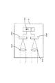
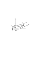
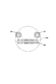
障害物監視ユニット30は、オートフォーカス(以下、AFと呼ぶ。)用測距センサとしてのAF用パッシブセンサ31(31R,31FR,31FM,31FL,31L,31CL))とその通信用インターフェイスであるAFセンサ通信I/O32と、照明用LED33と、各LEDに駆動電流を供給するLEDドライバ34とから構成されている。まず、AF用パッシブセンサ31の構成について説明する。図3はAF用パッシブセンサ31の概略構成を示している。二軸のほぼ平行な光学系31a1,31a2と、同光学系31a1,31a2の結像位置にほぼそれぞれ配設されたCCDラインセンサ31b1,31b2と、各CCDラインセンサ31b1,31b2の撮像イメージデータを外部に出力するための出力I/O31cとを備えている。
The
CCDラインセンサ31b1,31b2は160〜170画素のCCDセンサを有しており、各画素ごとに光量を表す8ビットのデータを出力可能となっている。光学系が二軸であるので、結像イメージには距離に応じたずれが生じており、それぞれのCCDラインセンサ31b1,31b2が出力するデータのずれに基づいて距離を計測できる。例えば、近距離になるほど結像イメージのずれが大きく、遠距離になるほど結像イメージのずれはなくなっていく。従って、一方の出力データにおける4〜5画素毎のデータ列を画報の出力データ中でスキャンし、元のデータ列のアドレスと発見されたデータ列のアドレスとの相違を求め、相違量で予め用意しておいた相違量−距離変換テーブルを参照し、実際の距離を求めることになる。 The CCD line sensors 31b1 and 31b2 have a CCD sensor of 160 to 170 pixels, and can output 8-bit data representing the amount of light for each pixel. Since the optical system is biaxial, the imaged image has a shift corresponding to the distance, and the distance can be measured based on the shift of data output from the CCD line sensors 31b1 and 31b2. For example, the shift of the image is larger as the distance is shorter, and the shift of the image is eliminated as the distance is longer. Therefore, the data string for every 4 to 5 pixels in one output data is scanned in the output data of the image report, and the difference between the address of the original data string and the address of the discovered data string is obtained. The actual distance is obtained by referring to the prepared difference amount-distance conversion table.
AF用パッシブセンサ31R,31FR,31FM,31FL,31L,31CLのうち、AF用パッシブセンサ31FR,31FM,31FLは正面の障害を検知するために利用され、AF用パッシブセンサ31R,31Lは前方左右直前の障害を検知するために利用され、AF用パッシブセンサ31CLは前方天井までの距離を検知するために利用されている。
Of the AF
図4は正面と前方左右直前の障害をAF用パッシブセンサ31で検知する際の原理を示している。これらのAF用パッシブセンサ31は周囲の床面に対して斜めに向けて配置されている。対向方向に障害物が無い場合、AF用パッシブセンサ31による測距距離はほぼ全撮像範囲においてL1となる。しかし、図面で一点鎖線で示すように段差がある場合、その測距距離はL2となる。測距距離が伸びたら下がる段差があると判断できる。また、二点鎖線で示すように上がる段差があれば測距距離はL3となる。障害物があるときも上がる段差と同様に測距距離は同障害物までの距離として計測され、床面よりも短くなる。
FIG. 4 shows the principle for detecting an obstacle immediately before the front and left and right with the AF
本実施形態においては、AF用パッシブセンサ31を前方の床面に斜めに配向した場合、その撮像範囲は約10cmとなった。本自走式クリーナの幅が30cmであったので、三つのAF用パッシブセンサ31FR,31FM,31FLについては撮像範囲が重ならないように僅かに角度を変えて配置している。これにより、三つのAF用パッシブセンサ31FR,31FM,31FLにより前方方向の30cmの範囲での障害物と段差を検知できるようになっている。むろん、検知幅はセンサの仕様や取付位置などに応じて変化し、実際に必要となる幅に応じた数のセンサを利用すればよい。
In the present embodiment, when the AF
一方、前方左右直前の障害を検知するAF用パッシブセンサ31R,31Lについては撮像範囲を垂直方向を基準として床面に対して斜めに配置している。また、AF用パッシブセンサ31Rを本体左方に取り付けつつ本体中央を横切って右方直前位置から本体幅を超えた右方の範囲を撮像するように対向させてあり、AF用パッシブセンサ31Lを本体右方に取り付けつつ本体中央を横切って左方直前位置から本体幅を超えた左方の範囲を撮像するように対向させてある。
On the other hand, the AF
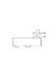
クロスさせないで左右の直前位置を撮影するようにすると、センサは急角度で床面に対面させなければならず、このようにすると撮像範囲が極めて狭くなってしまうので、複数のセンサが必要となる。このため、敢えてクロスさせる配置とし、撮像範囲を広げて少ない数のセンサで必要範囲をカバーできるようにしている。また、撮像範囲を垂直方向を基準として斜めに配置するのは、CCDラインセンサの並び方向が垂直方向に向くことを意味しており、図5に示すように撮像できる幅がW1となる。ここで、撮像範囲の右側で床面までの距離L4は短く、左側で距離L5が長くなっている。本体BDの側面の境界ラインが図面上の波線位置Bであると、境界ラインまでの撮像範囲は段差の検知などに利用され、境界ラインを超える撮像範囲は壁面の有無を検知するために利用される。 If the left and right positions are photographed without crossing, the sensor must face the floor surface at a steep angle, and in this case, the imaging range becomes extremely narrow, so a plurality of sensors are required. . For this reason, the arrangement is made to cross, and the imaging range is widened so that the required range can be covered with a small number of sensors. Further, arranging the imaging range obliquely with respect to the vertical direction means that the arrangement direction of the CCD line sensors is directed in the vertical direction, and the width capable of imaging is W1, as shown in FIG. Here, the distance L4 to the floor surface is short on the right side of the imaging range, and the distance L5 is long on the left side. If the boundary line on the side surface of the main body BD is a wavy position B on the drawing, the imaging range up to the boundary line is used for detecting a step, and the imaging range exceeding the boundary line is used for detecting the presence or absence of a wall surface. The
前方天井までの距離を検知するAF用パッシブセンサ31CLは天井に対面している。通常はAF用パッシブセンサ31CLが検知する床面から天井までの距離が一定であるが、壁面に近づいてくると撮像範囲が天井ではなく壁面となるので、測距距離が短くなってくる。従って、前方壁面の存在をより正確に検知できる The AF passive sensor 31CL that detects the distance to the front ceiling faces the ceiling. Normally, the distance from the floor surface to the ceiling detected by the AF passive sensor 31CL is constant, but when approaching the wall surface, the imaging range becomes the wall surface instead of the ceiling, and the distance measurement distance becomes shorter. Therefore, the presence of the front wall surface can be detected more accurately.
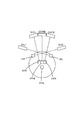
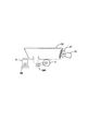
図6は各AF用パッシブセンサ31R,31FR,31FM,31FL,31L,31CLの本体BDへの取り付け位置を示すとともに、それぞれの床面での撮像範囲を括弧付きの符号で対応させて示している。なお、天井については撮像範囲は省略している。
FIG. 6 shows the attachment positions of the AF
AF用パッシブセンサ31R,31FR,31FM,31FL,31Lの撮像を証明するように白色LEDからなる右照明用LED33Rと、左照明用LED33Lと、前照明用LED33Mを備えており、LEDドライバ34はCPU11からの制御指示に基づいて駆動電流を供給して照明できるようになっている。これにより、夜間であったり、テーブルの下などの暗い場所でもAF用パッシブセンサ31から有効な撮像イメージのデータを得ることができるようになる。
In order to prove the imaging of the AF
走行系ユニット40は、モータドライバ41R,41Lと、駆動輪モータ42R,42Lと、この駆動輪モータ42R,42Lにて駆動される図示しないギアユニットと駆動輪を備えている。駆動輪は本体BDの左右に一輪ずつ配置されており、この他に駆動源を持たない自由転動輪が本体の前方側中央下面に取り付けられている。駆動輪モータ42R,42Lは回転方向と回転角度をモータドライバ41R,41Lによって詳細に駆動可能であり、各モータドライバ41R,41LはCPU11からの制御指示に応じて対応する駆動信号を出力する。また、駆動輪モータ42R,42Lと一体的に取り付けられているロータリーエンコーダの出力から現実の駆動輪の回転方向と回転角度が正確に検知できるようになっている。なお、ロータリーエンコーダは駆動輪と直結させず、駆動輪の近傍に自由回転可能な従動輪を取り付け、同従動輪の回転量をフィードバックさせることによって駆動輪にスリップが生じているような場合でも現実の回転量を検知できるようにしても良い。走行系ユニット40には、この他に地磁気センサ43が備えられており、地磁気に照らし合わせて走行方向を判断できるようになっている。また、加速度センサ44はXYZ三軸方向における加速度を検知し、検知結果を出力する。
The travel system unit 40 includes
ギアユニットや駆動輪は各種のものを採用可能であり、円形のゴム製タイヤを駆動させるようにしたり、無端ベルトを駆動させるようにして実現しても良い。 Various types of gear units and drive wheels can be employed, and may be realized by driving a circular rubber tire or driving an endless belt.
本自走式掃除機における掃除機構は、前方両サイドに配置されて本体BDの進行方向における両側寄りのゴミなどを当該本体BDにおける中央付近にかき寄せるサイドブラシと、本体の中央付近にかき寄せられたゴミをすくい上げるメインブラシと、同メインブラシによりすく上げられるゴミを吸引してダストボックス内に収容する吸引ファンとから構成されている。クリーナ系ユニット50は、各ブラシを駆動するサイドブラシモータ51R,51Lとメインブラシモータ52、それぞれのモータに駆動電力を供給するモータドライバ53R,53L,54と、吸引ファンを駆動する吸引モータ55と、同吸引モータに駆動電力を供給するモータドライバ56とから構成されている。サイドブラシやメインブラシを使用した掃除は床面の状況やバッテリーの状況やユーザの指示などに応じてCPU11が適宜判断して制御するようにしている。
The cleaning mechanism in the self-propelled cleaner is arranged on both front sides and scrapes dust near the both sides in the traveling direction of the main body BD to the vicinity of the center of the main body BD, and the vicinity of the center of the main body. The main brush scoops up the dust and a suction fan that sucks up the dust scooped up by the main brush and stores it in the dust box. The
図10は、サイドブラシSBと、メインブラシMBの配置を平面図により示している。本体BDの中央部分を横切るようにメインブラシMBが配置されており、その前方側の左右に一対のサイドブラシSB,SBが配置されている。また、図11は、サイドブラシSBと、メインブラシMBと、吸引ファンDFの配置を概略断面図により示している。メインブラシMBは、ダストボックスDBに連通する吸引口DTの下部に配置され、ゴミを掻き上げ、ダストボックスDBの後方側に配置した吸引ファンDFにて負圧を発生し、掻き上げたゴミをダストボックスDB内に吸い込んで捕捉する。 FIG. 10 is a plan view showing the arrangement of the side brush SB and the main brush MB. A main brush MB is disposed across the central portion of the main body BD, and a pair of side brushes SB and SB are disposed on the left and right sides of the front side of the main brush MB. FIG. 11 is a schematic sectional view showing the arrangement of the side brush SB, the main brush MB, and the suction fan DF. The main brush MB is disposed below the suction port DT communicating with the dust box DB, scrapes up dust, generates negative pressure with the suction fan DF disposed on the rear side of the dust box DB, and removes the scraped dust into the dust box DB. Inhale and capture.
カメラ系ユニット60は、それぞれ視野角の異なる二つのCMOSカメラ61,62を備えており、本体BDの正面方向であってそれぞれことなる仰角にセットされている。また、各カメラ61,62への撮像を指示するとともに撮像イメージを出力するためのカメラ通信I/O63も備えられている。さらに、カメラ61,62の撮像方向に対面させて15コの白色LEDからなるカメラ用照明LED64と、同LEDに照明用駆動電力を供給するためのLEDドライバ65を備えている。
The
無線LANユニット70は、無線LANモジュール71を有しており、CPU11は所定のプロトコルに従って外部LANと無線によって接続可能となっている。無線LANモジュール71は、図示しないアクセスポイントの存在を前提として、同アクセスポイントはルータなどを介して外部の広域ネットワーク(例えばインターネット)に接続可能な環境となっていることとする。従って、インターネットを介した通常のメールの送受信やWEBサイトの閲覧といったことが可能である。なお、無線LANモジュール71は、規格化されたカードスロットと、同スロットに接続される規格化された無線LANカードなどから構成されている。むろん、カードスロットは他の規格化されたカードを接続することも可能である。
The
次に、上記構成からなる自走式掃除機の動作について説明する。
(1)清掃動作について
図7及び図8は上記CPU11が実行する制御プログラムに対応したフローチャートを示しており、図9は同制御プログラムに従って本自走式掃除機が走行する走行順路を示す図である。
Next, the operation of the self-propelled cleaner having the above configuration will be described.
(1) Cleaning Operation FIGS. 7 and 8 are flowcharts corresponding to the control program executed by the CPU 11, and FIG. 9 is a diagram showing a traveling route on which the self-propelled cleaner travels according to the control program. is there.
電源オンにより、CPU11は図7の走行制御を開始する。ステップS110ではAF用パッシブセンサ31の検知結果を入力し、前方エリアを監視する。前方エリアの監視に使用するのはAF用パッシブセンサ31FR,31FM,31FLの検知結果であり、平坦な床面であれば、その撮像イメージから得られるのは図4に示す斜め下方の床面までの距離L1である。それぞれのAF用パッシブセンサ31FR,31FM,31FLの検知結果に基づき、本体BD幅に一致する前方の床面が平坦であるか否かが判断できる。ただし、この時点では、各AF用パッシブセンサ31FR,31FM,31FLが対面している床位置と本体の直前位置までの間の情報は何も得られていないので死角となる。
When the power is turned on, the CPU 11 starts the traveling control shown in FIG. In step S110, the detection result of the AF
ステップS120ではモータドライバ41R,41Lを介して駆動輪モータ42R,42Lに対してそれぞれ回転方向を異にしつつ同回転量の駆動を指示する。これにより本体BDはその場で回転を始める。同じ場所での360度の回転(スピンターン)に要する駆動モータ42R,42Lの回転量は予め分かっており、CPU11は同回転量をモータドライバ41R,41Lに指示している。
In step S120, the
スピンターン中、CPU11はAF用パッシブセンサ31R,31Lの検知結果を入力し、本体BDの直前位置の状況を判断する。上述した死角はこの間の検知結果により、ほぼなくなり、段差、障害物が何も無い場合、周囲の平坦な床面の存在を検知できる。
During the spin turn, the CPU 11 inputs the detection results of the AF
ステップS130ではCPU11はモータドライバ41R,41Lを介して駆動輪モータ42R,42Lに対してそれぞれ同回転量の駆動を指示する。これにより本体BDは直進を開始する。直進中、CPU11はAF用パッシブセンサ31FR,31FM,31FLの検知結果を入力し、正面に障害物がいないか判断しながら前進する。そして、同検知結果から正面に障害物たる壁面が検知できたら、その壁面の所定距離だけ手前で停止する。
In step S130, the CPU 11 instructs the
ステップS140では右に90度回転する。ステップS130で壁面の所定距離だけ手前で停止したが、この所定距離は本体BDが回転動作するときに同壁面に衝突せず、また、直前および左右の状況を判断するためのAF用パッシブセンサ31R,31Lが検知する本体幅の外側にあたる範囲の距離である。すなわち、ステップS130にてAF用パッシブセンサ31FR,31FM,31FLの検知結果に基づいて停止し、ステップS140にて90度回転するときには、少なくともAF用パッシブセンサ31Lが壁面の位置を検知できる程度の距離となるようにしている。また、90度回転するときには、上記AF用パッシブセンサ31R,31Lの検知結果に基づいて直前位置の状況を判断しておく。図9はこのようにしてたどり着いた平面図で見たときの部屋の左下角を清掃開始位置として清掃走行を開始する状況を示している。
In step S140, it is rotated 90 degrees to the right. In step S130, the actuator stops at a predetermined distance on the wall surface, but this predetermined distance does not collide with the wall surface when the main body BD rotates, and the AF
清掃走行開始位置へたどり着く方法はこれ以外にも各種の方法がある。壁面に当接する状況において右に90度回転するだけでは、最初の壁面の途中から始めることになることもあるため、図9に示すように左下角の最適位置にたどり着くのであれば、壁面に当接して左90度回転し、正面の壁面に当接するまで前進し、当接した時点で180度回転することも望ましい走行制御である。 There are various other methods for reaching the cleaning travel start position. If you rotate 90 degrees to the right while in contact with the wall surface, it may start from the middle of the first wall surface, so if you reach the optimal position in the lower left corner, as shown in FIG. It is also desirable travel control to rotate 90 degrees to the left, move forward until it contacts the front wall surface, and rotate 180 degrees when contacted.
ステップS150では、清掃走行を実施する。同清掃走行のより詳細なフローを図8に示している。前進走行するにあたり、ステップS210〜S240にて各種のセンサの検知結果を入力している。ステップS210では前方監視センサデータ入力しており、具体的にはAF用パッシブセンサ31FR,31FM,31FL,31CLの検知結果を入力し、走行範囲の前方に障害物あるいは壁面が存在しないか否かの判断に供することになる。なお、前方監視という場合には、広い意味での天井の監視も含めている。 In step S150, cleaning travel is performed. A more detailed flow of the cleaning traveling is shown in FIG. When traveling forward, detection results of various sensors are input in steps S210 to S240. In step S210, forward monitoring sensor data is input. Specifically, detection results of AF passive sensors 31FR, 31FM, 31FL, and 31CL are input, and whether or not an obstacle or a wall surface exists in front of the traveling range. It will be used for judgment. In addition, in the case of forward monitoring, monitoring of the ceiling in a broad sense is included.
ステップS220では段差センサデータ入力をしており、具体的にはAF用パッシブセンサ31R,31Lの検知結果を入力し、走行範囲の直前位置に段差がないか否かの判断に供することになる。また、壁面や障害物に沿って平行に移動するときには壁面や障害物までの距離を計測し、平行に移動しているか否かの判断に供することになる。
In step S220, step sensor data is input. Specifically, the detection results of the AF
ステップS230では地磁気センサデータ入力をしており、具体的には地磁気センサ43の検知結果を入力し、直進走行中に走行方向が変化していないか否かを判断するのに利用する。例えば、清掃走行開始時の地磁気の角度を記憶しておき、走行中に検出される角度が記憶されている角度と異なった場合には、左右の駆動輪モータ42R,42Lの回転量をわずかに異ならせて進行方向を修正し、元の角度へ戻す。例えば、地磁気の角度に基づいて角度が増加する方向へ変化(359度から0度への変化は例外点となる))したら左方向へ軌道を修正する必要があり、右の駆動輪モータ42Rの回転量を左の駆動輪モータ42Lの回転量よりも僅かに増やすようにそれぞれのモータドライバ41R,41Lへ駆動を制御する指示を出力する。
In step S230, geomagnetic sensor data is input. Specifically, the detection result of the
ステップS240では、加速度センサデータ入力をしており、具体的には加速度センサ44の検知結果を入力し、走行状態の確認に供することになる。例えば、直進走行開始時に概ね一定の方向への加速度を検知できれば正常な走行と判断できるが、回転する加速度を検知すれば片方の駆動輪モータが駆動されていないような異常を判断できる。また、正常な範囲の加速度値を超えたら段差などから落下したり、横転したような異常を判断できる。そして、前進中に後方にあたる方向への大きな加速度を検知したら前方の障害物に当接した異常を判断できる。このように、加速度値を入力して目標加速度を維持するとか、その積分値に基づいて速度を得るというような走行に対する直接的な制御をすることはないが、異常検出の目的として加速度値を有効に利用している。
In step S240, acceleration sensor data is input. Specifically, the detection result of the
ステップS250では、ステップS210とステップS220で入力したAF用パッシブセンサ31FR,31FM,31CL,31FL,31R,31Lの検知結果に基づいて障害物の判定を行う。障害物の判定は、正面、天井、直前のそれぞれの部位毎に行う。正面は障害物あるいは壁面の意味として判定し、直前は段差の判定とともに走行範囲外の左右の状況、例えば壁面の有無などを判定する。天井は鴨居などによって天井までの距離が下がってきているときに正面に障害物がないとしても、そこからは廊下であって室外に出てしまうことを判定するのに利用される。 In step S250, the obstacle is determined based on the detection results of the AF passive sensors 31FR, 31FM, 31CL, 31FL, 31R, and 31L input in steps S210 and S220. Obstacles are determined for each of the front, ceiling, and immediately preceding parts. The front is determined as the meaning of an obstacle or a wall, and immediately before the step is determined, the right and left conditions outside the traveling range, for example, the presence or absence of a wall are determined. Even if there is no obstacle in the front when the distance to the ceiling is decreasing due to a duck or the like, the ceiling is used to determine that it is a corridor and goes out of the room.
ステップS260では、各センサからの検知結果を総合的に判断し、回避の必要があるか否かを判断する。回避の必要がない限りステップS270の清掃処理を実行する。清掃処理は、サイドブラシとメインブラシを回転させつつ、ゴミを吸引する処理であり、具体的にはモータドライバ53R,53L,54,56に各モータ51R,51L,52,55を駆動させる指示を出力する。むろん、走行中は常に同指示を出しているのであり、後述するように清掃走行の終端条件が成立したときに停止させることになる。
In step S260, the detection result from each sensor is comprehensively determined to determine whether or not it is necessary to avoid it. Unless there is a need for avoidance, the cleaning process in step S270 is executed. The cleaning process is a process of sucking dust while rotating the side brush and the main brush. Specifically, the
一方、回避が必要と判断されると、ステップS280にて右に90度ターンを実施する。このターンは同じ位置での90度ターンであり、モータドライバ41R,41Lを介して駆動輪モータ42R,42Lに対してそれぞれ回転方向を異にしつつ90度ターンに必要なだけの回転量の駆動を指示する。回転方向は右の駆動輪に対して後退の方向であり、左の駆動輪に対して前進の方向となる。回転中は段差センサであるAF用パッシブセンサ31R,31Lの検知結果を入力し、障害物の状況を判断する。例えば、正面に障害を検知し、右90度ターンを実施したとき、AF用パッシブセンサ31Rが前方右方の直前位置に壁面を検知しなければ単に正面の壁面に当接したといえるが、回転後も前方右方の直前位置に壁面を検知しているのであれば、角部に入り込んでいるといったことが判断できる。また、右90度回転時にAF用パッシブセンサ31R,31Lのいずれもが前方直前に障害を検知しなければ、壁面に当接したのではなく、小さな障害物などであったと判断できる。
On the other hand, if it is determined that avoidance is necessary, a 90 degree turn to the right is performed in step S280. This turn is a 90-degree turn at the same position, and drives the rotation amount necessary for the 90-degree turn while changing the rotation direction with respect to the
ステップS290では障害物を走査しながらの進路変更のため前進する。壁面に当接し、右90度回転後、前進していく。壁面の手前で停止したのであれば、前進の走行量は概ね本体BDの幅分である。その分の前進後、ステップS300では再度右90度ターンを実施する。 In step S290, the vehicle advances to change the course while scanning the obstacle. It abuts against the wall and rotates forward 90 degrees to the right. If stopped before the wall surface, the forward travel amount is approximately the width of the main body BD. After advance by that amount, in step S300, the right 90 degree turn is performed again.
以上の移動の間、正面の障害物、前方左右の障害物の有無は常に走査して状況を確認しており、部屋の中の障害物の有無の情報として記憶していく。 During the above movement, the presence or absence of front obstacles and front and right obstacles is always scanned to check the situation and stored as information on the presence or absence of obstacles in the room.
ところで、上述した説明では、右90度ターンを2度実行したが、次に前方に壁面を検知した時点で右90度ターンを実行すると元に戻ってしまうので、二度の90度ターンは、右を繰り返したら、次は左を繰り返し、その次は右というように交互に行っていく。従って、奇数回目の障害物回避では右ターン、偶数回目の障害物回避では左ターンとなる。 By the way, in the above description, the right 90 degree turn is executed twice. However, when the right 90 degree turn is executed next when the wall surface is detected forward, the turn returns to the original state. If you repeat the right, the next is the left, the next is the right, and so on. Therefore, a right turn is used for the odd-numbered obstacle avoidance and a left turn is used for the even-numbered obstacle avoidance.
以上のように障害物を回避しながら、部屋の中をつづら折り状に走査して清掃走行を継続していく。そして、部屋の終端にきたか否かをステップS310にて判断する。清掃走行の終端は、二度目のターン後に、壁面に沿って前進して清掃走行を実施し、その後で前方に障害物を検知した場合と、既に走行した部位に入り込んだ場合である。すなわち、前者hつづれ折り状に走行していった最後の端から端への走行後に生じる終了条件であり、後者は後述するように未清掃エリアを発見して再度清掃走行を開始したときの終了条件になる。 As described above, the cleaning traveling is continued by scanning the room in a zigzag manner while avoiding the obstacles. Then, in step S310, it is determined whether or not the end of the room has been reached. The end of the cleaning travel is when the second turn is advanced along the wall surface to perform the cleaning travel, after which an obstacle is detected forward and when the vehicle has already traveled. In other words, the former is an end condition that occurs after the last end-to-end travel that traveled in a folded manner, and the latter ends when an uncleaned area is found and cleaning travel is started again as will be described later. It becomes a condition.
この終端条件が成立していなければ、ステップS210へ戻って以上の処理を繰り返す。終端条件が成立していれば、本清掃走行のサブルーチン処理を終了し、図7に示す処理へ復帰する。 If this termination condition is not satisfied, the process returns to step S210 and the above processing is repeated. If the termination condition is satisfied, the subroutine process of the main cleaning traveling is terminated and the process returns to the process shown in FIG.
復帰後、ステップS160では、これまでの走行経路と走行経路の周囲の状況から未清掃エリアが残っていないか判断する。未清掃エリアの有無の判断は公知の各種の手法を利用可能であり、一例としてこれまでの走行経路をマッピングして記憶していく手法を利用可能である。この例では、上述したロータリーエンコーダの検知結果に基づいて室内での走行経路と、走行中に検出した壁面の有無を記憶領域に確保指定あるマップ上に書き込んでいっており、周囲の壁面が途絶えることなく連続し、かつ、室内の存在していた障害物の周囲も連続し、かつ、室内で障害物を除く範囲を全て走行したか否かで判断する。未清掃エリアが見つかれば、ステップS170で未清掃エリアの開始点へと移動し、ステップS150に戻って清掃走行を再開する。 After returning, in step S160, it is determined whether or not an uncleaned area remains from the previous travel route and the situation around the travel route. Various known methods can be used to determine whether or not there is an uncleaned area. For example, a method of mapping and storing a travel route so far can be used. In this example, based on the detection result of the rotary encoder described above, the indoor travel route and the presence / absence of the wall surface detected during the travel are written on a map designated to be secured in the storage area, and the surrounding wall surface is interrupted. It is determined whether or not the vehicle is running continuously, and the surroundings of obstacles that existed in the room are also continuous, and the entire range excluding the obstacles has been traveled. If an uncleaned area is found, it moves to the starting point of an uncleaned area at step S170, returns to step S150, and restarts cleaning travel.
未清掃エリアが複数箇所に散在していたとしても、上述したような清掃走行の終端条件が成立するごとに、未清掃エリアの検出を繰り返していくことにより、最終的には未清掃エリアがなくなる。 Even if the uncleaned areas are scattered in a plurality of places, the uncleaned areas are finally eliminated by repeating the detection of the uncleaned areas every time the termination condition of the cleaning traveling as described above is satisfied. .
(2)ペットモードについて
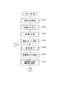
図12は、本自走式掃除機における動作モードを選択するために液晶表示パネル15b上にて表示し、操作用スイッチ15aにて操作させるために操作画面を示している。同図に示すように、動作モードとして、自走清掃モードと、ペットモードとを操作用スイッチ15aを操作して選択する。CPU11は、自走清掃モードを選択した場合に、上述した図7及び図8にフローチャートに従って制御し、ペットモードを選択した場合に図13に示すフローチャートに従って制御を実施する。
(2) About Pet Mode FIG. 12 shows an operation screen displayed on the liquid
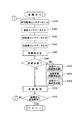
ペットモードが選択されると、CPU11は図13に示すフローチャートに従って処理を進める。まず、ステップS400では、人体センサ21の検知結果を取得し、周囲に人体があるか否かを判断する。ペットモードは周囲に人体を検知したときに、喜び、怒り、悲しみ、楽しさを表現する音を発生しつつ、動作を行なう。このため、人体センサ21にて人体を検知するまで、ステップS400で待機することになる。 When the pet mode is selected, the CPU 11 advances the process according to the flowchart shown in FIG. First, in step S400, the detection result of the human body sensor 21 is acquired, and it is determined whether or not there is a human body around. The pet mode operates while generating sounds expressing joy, anger, sadness and enjoyment when a human body is detected in the surroundings. For this reason, it waits in step S400 until the human body sensor 21 detects a human body.
人体センサ21にて人体を検知すると、ステップS402にて人体に対面するようにポジショニングを行う。ポジショニングは、人体と本体BDとの相対角度を求め、同相対角度を解消する駆動動作を行なう。相対角度を検知するにあたり、各人体センサ21が赤外線発光動体における赤外線強度を出力する場合と、単に赤外線発光動体の有無を出力する場合とがある。 When the human body 21 is detected by the human body sensor 21, positioning is performed so as to face the human body in step S402. In the positioning, a relative angle between the human body and the main body BD is obtained, and a driving operation for eliminating the relative angle is performed. In detecting the relative angle, there are cases where each human body sensor 21 outputs the infrared intensity of the infrared light emitting moving body, or simply outputs the presence or absence of the infrared light emitting moving body.
赤外線強度を出力する場合、単一の人体センサ21だけが検知するのではなく、複数の人体センサ21が検知すると考えられる。この場合、強度の強い二つの人体センサ21の検知出力を得て、それぞれの対向方向に挟まれる90度の角度範囲内で赤外線発光動体の角度を検知する。この場合、二つの人体センサ21の検知出力の強度比を求め、同強度比を利用して予め実験して作成しておいたテーブルを参照する。このテーブルには強度比と角度との対応が関連づけて記憶されているので、同90度の範囲内での検知対象物の角度が判断でき、さらに検知出力を利用した二つの人体センサ21の取り付け位置に基づいて本体BDとの相対角度を求める。例えば、検知出力の強度の強い二つの人体センサ21が右側面の人体センサ21fr,21rrであり、かつ、強度比から90度の範囲内における人体センサ21frの側の30度の角度が上記テーブルから参照されたとすると、右側面の90度の範囲内で前方側の30度の角度であるから、本体正面に対しては、45度+30度=75度の相対角度ということになる。 When outputting the infrared intensity, it is considered that not only a single human sensor 21 but also a plurality of human sensors 21 detect it. In this case, the detection outputs of the two strong human body sensors 21 are obtained, and the angle of the infrared light emitting moving body is detected within an angle range of 90 degrees sandwiched between the opposing directions. In this case, the intensity ratio of the detection outputs of the two human body sensors 21 is obtained, and a table created by experiment in advance using the intensity ratio is referred to. Since the correspondence between the intensity ratio and the angle is stored in this table in association with each other, the angle of the object to be detected within the range of 90 degrees can be determined, and the attachment of the two human body sensors 21 using the detection output. Based on the position, a relative angle with the main body BD is obtained. For example, the two human body sensors 21 having high detection output intensity are the human body sensors 21fr and 21rr on the right side surface, and the angle of 30 degrees on the human body sensor 21fr side within the range of 90 degrees from the intensity ratio is from the above table. If it is referred to, the angle is 30 degrees on the front side within the range of 90 degrees on the right side surface, and therefore, relative to the front of the main body, the angle is 45 degrees + 30 degrees = 75 degrees.
一方、単に赤外線発光動体の有無を出力する場合は、基本的に本体BDに対する8つの相対角度だけを検知する。すなわち、いずれか一つの人体センサ21だけが検知出力を出した場合は、同検知出力を出力した人体センサ21の取付位置の角度を相対角度とし、二つの人体センサ21が検知出力を出した場合は、これら二つの人体センサ21の取付位置の中間の角度を相対角度とし、三つの人体センサ21が検知出力を出した場合は、人体センサ21の取付位置の角度を相対角度とする。すなわち、等間隔で複数の人体センサが取り付けられている場合、偶数個であれば中央の二つの人体センサの取付位置の中間であり、奇数個であれば中央の人体センサの取付位置となる。 On the other hand, when the presence / absence of an infrared light emitting moving object is simply output, basically only eight relative angles with respect to the main body BD are detected. That is, when only one of the human body sensors 21 outputs a detection output, the angle of the mounting position of the human body sensor 21 that outputs the detection output is a relative angle, and the two human body sensors 21 output the detection output. The relative angle is an intermediate angle between the mounting positions of the two human body sensors 21, and when the three human body sensors 21 output a detection output, the angle of the mounting position of the human body sensor 21 is the relative angle. That is, when a plurality of human body sensors are mounted at equal intervals, if the number is even, it is an intermediate position between the mounting positions of the center two human sensors, and if the number is odd, the center human sensor is mounted.
このようにして相対角度を求めたら、同相対角度に本体BDの正面が対面するように左右の駆動輪を駆動させる。回転動作であるから、同じ場所でのターン動作であり、左右の駆動輪モータ42R,42Lを逆方向に所定の回転量だけ駆動させるようにモータドライバ41R,41Lに指示を与える。
When the relative angle is obtained in this way, the left and right drive wheels are driven so that the front of the main body BD faces the relative angle. Since it is a rotation operation, it is a turn operation at the same place, and an instruction is given to the
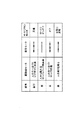
ステップS404では表現する感情を選択する。図14に示すように、表現可能な感情は、「喜び」、「怒り」、「悲しみ」、「楽しさ」の四つである。感情を選択する手法は様々であり、各種の感情選択専用のセンサを配置して決定することも可能である。本実施例においては、感情選択は乱数を発生し、同乱数に基づいてランダムに決定することにしている。 In step S404, the emotion to be expressed is selected. As shown in FIG. 14, there are four emotions that can be expressed: “joy”, “anger”, “sadness”, and “fun”. There are various techniques for selecting emotions, and various types of emotion selection sensors can be arranged and determined. In the present embodiment, the emotion selection generates a random number and randomly determines based on the random number.
ステップS404にて感情を決定したら、ステップS406〜S410の判断により、決定した感情に対応した動作と音の発生を実行する。感情と、動作と、音との対応関係の一例を図14に示している。 If the emotion is determined in step S404, the operation corresponding to the determined emotion and the generation of sound are executed according to the determination in steps S406 to S410. FIG. 14 shows an example of the correspondence between emotions, actions, and sounds.
「喜び」は、あたかもペットの犬が飼い主に向かってじゃれついてくる様子を模倣し、人の方向に向かってジグザグに前進し、その際にサイドブラシを高速に回すという動作を行う。また、吸引モータを、短く動かした後、長く動かすというパターンで繰り返し駆動する。これにより、ゴッ、ゴー、ゴッ、ゴーというような吸気音が継続し、喜びを表せる。 “Pleasure” imitates the appearance of a pet dog fluttering toward the owner, moves forward in a zigzag direction toward the person, and rotates the side brush at that time. Further, the suction motor is repeatedly driven in a pattern in which the suction motor is moved short and then moved long. As a result, inspiratory sounds such as “go, go, go, go” continue and express joy.
「怒り」は、あたかもペットの犬が不審者に向かって威嚇する様子を模倣し、人の方向に向かってゆっくりバックした後、急に前進する。その際にサイドブラシは、低速の回転で断続的に回転させる。また、吸引モータを、短めに、断続的に動かすというパターンで繰り返し駆動する。これにより、ゴーッ、ゴーッというような吸気音が継続し、威嚇する怒りを表せる。 "Anger" imitates the appearance of a pet dog threatening towards a suspicious person, and slowly moves back toward the direction of the person and then moves forward rapidly. At that time, the side brush is rotated intermittently at a low speed. Further, the suction motor is repeatedly driven in a pattern of moving intermittently in a short manner. As a result, inhalation sounds such as “go” and “go” continue, and the angry anger can be expressed.
「悲しみ」は、あたかもペットの犬が飼い主に向かってさみしく寄ってくる様子を模倣し、人の方向に向かってゆっくり前進する。その際にサイドブラシは停止したままとする。また、吸引モータは、長く、弱く動かすというパターンで繰り返し駆動する。これにより、クーン、クーンというような吸気音が継続し、悲しみを表せる。 “Sadness” imitates the appearance of a pet dog approaching the owner, and slowly advances toward the person. At that time, the side brush remains stopped. The suction motor is repeatedly driven in a pattern of long and weak movement. As a result, inspiratory sounds such as coon and coon continue, and sorrow can be expressed.
「楽しさ」は、喜びと似てはいるものの、あたかもペットの犬が飼い主の周りを走り回る様子を模倣し、人の周りを回り、その際にサイドブラシを交互に反転させるという動作を行う。また、吸引モータを、短く二回動かした後、長く動かすというパターンで繰り返し駆動する。これにより、ゴッ、ゴッ、ゴー、ゴッ、ゴッ、ゴーというような吸気音が継続し、楽しさを表せる。 “Fun” is similar to joy, but it mimics the appearance of a pet dog running around the owner, turns around the person, and inverts the side brushes alternately. Further, the suction motor is repeatedly driven in a pattern in which the suction motor is rotated twice and then moved long. As a result, inspiratory sounds such as bangs, bangs, go, bangs, bangs, and go continue, and enjoyment can be expressed.
これらの各動作は、ステップS406〜S410の判断で感情毎に分岐され、喜びであればステップS412〜S416、怒りであればステップS418〜S422、悲しみであればステップS424〜S428、楽しさであればステップS430〜S434で実施する。 Each of these actions is branched for each emotion according to the judgment in steps S406 to S410. If it is pleasure, steps S412 to S416, if it is anger, steps S418 to S422, if it is sad, steps S424 to S428. For example, the steps S430 to S434 are performed.
喜びの場合、ステップS412ではジグザグに前進する動きを駆動機構にて実現するが、ジグザグに駆動するためには左右の駆動輪モータ42R,42Lを交互に同量ずつ回転させればよい。ステップS414では喜びのパターンの吸気音を発生させるため、吸引モータ55に対して、短く動かした後、長く動かすというパターンで繰り返しモータドライバ56から電力を供給させることになる。ステップS416ではサイドブラシを高速に回転させるようにモータドライバ53R,53Lより電力を供給させる。
In the case of joy, in step S412, the zigzag movement is realized by the drive mechanism. To drive zigzag, the left and right
怒りの場合、ステップS418ではゆっくりバックした後、急に前進する動きを駆動機構にて実現するが、左右の駆動輪モータ42R,42Lに対して同量ずつ上述した動きとなるように回転させればよい。ステップS420では怒りのパターンの吸気音を発生させるため、吸引モータ55に対して、短めに、断続的に動かすというパターンで繰り返しモータドライバ56から電力を供給させることになる。ステップS422ではサイドブラシをゆっくりオンオフさせるようにモータドライバ53R,53Lより電力を供給させる。
In the case of anger, in step S418, after slowly backing up, the drive mechanism realizes a sudden forward movement, but the left and right
悲しみの場合、ステップS424ではゆっくり前進する動きを駆動機構にて実現するが、左右の駆動輪モータ42R,42Lに対して同量ずつゆっくり前進する動きとなるように回転させればよい。ステップS426では悲しみのパターンの吸気音を発生させるため、吸引モータ55に対して、長く、弱く動かすというパターンで繰り返しモータドライバ56から電力を供給させることになる。ステップS428ではサイドブラシを停止させるべくモータドライバ53R,53Lからの電力供給を停止させる。
In the case of sadness, in step S424, the slowly moving forward movement is realized by the drive mechanism, but it is only necessary to rotate the left and right
楽しさの場合、ステップS430では人も周りを回転させる動きを駆動機構にて実現する。このためには、一旦、現在の方向から90度スピンターンさせ、この状態から予め決めた半径の軌道を走行するように左右の駆動輪モータ42R,42Lに対する回転量を決定して回転させればよい。ステップS432では楽しさのパターンの吸気音を発生させるため、吸引モータ55に対して、短く二回動かした後、長く動かすというパターンで繰り返しモータドライバ56から電力を供給させることになる。ステップS434ではサイドブラシを交互に反転させるようにモータドライバ53R,53Lより電力を供給させる。
In the case of fun, in step S430, the person also performs a movement of rotating around by the drive mechanism. For this purpose, once a 90 degree spin turn is made from the current direction, and the amount of rotation for the left and right
人体の検知に対して上述した対応を決めておいて実施させることにより、自走式掃除機がペットのように振る舞い、かつ、掃除機としての個性を活かして吸気音をうまく利用して感情表現に役立つようにしている。 By determining and implementing the above-mentioned responses to human body detection, the self-propelled cleaner behaves like a pet and expresses emotions by making good use of the intake sound by taking advantage of its individuality as a cleaner. To help.
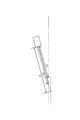
図15は、吸気音に変化を生じさせるために排気口EXに取り付けるアダプタADを指名している。排気口EXは本体BD後方側上面に短円筒形状として突出して形成されており、アダプタADは同円筒部分に装着できる短円筒部分とともに同短円筒部分から先細りとなるダクト部分を有している。ダクト部分の内部に笛のように音を発する形状を形成してあり、排気により、笛状の音を発生させることができるようになる。むろん、ダクト部分の形状を変化させることで各種の音を発生させることができ、ユーザーが複数の音色から選択して取り付けるようにしても良い。 FIG. 15 designates an adapter AD attached to the exhaust port EX in order to cause a change in the intake sound. The exhaust port EX is formed on the rear upper surface of the main body BD so as to project as a short cylinder, and the adapter AD has a short cylindrical part that can be attached to the cylindrical part and a duct part that tapers from the short cylindrical part. A shape that emits a sound like a whistle is formed inside the duct part, and a whistle-like sound can be generated by exhaust. Of course, various sounds can be generated by changing the shape of the duct portion, and the user may select and install from a plurality of timbres.
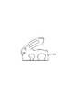
また、ペットらしさをより強調するために、図16に示すようなぬいぐるみ状のカバーCVを装着できるようにしても良い。この際、カバーCVの内部にいくつかのタッチセンサーを装着しておき、各タッチセンサーの検知状況に基づいて感情を選択させるようにすることが可能である。 Further, in order to further emphasize the character of a pet, a stuffed toy cover CV as shown in FIG. 16 may be attached. At this time, it is possible to attach several touch sensors to the inside of the cover CV and to select emotions based on the detection status of each touch sensor.
例えば、ユーザーがなでる仕草をタッチセンサーで検知すれば喜びを選択するし、喜んでいる状態でタッチしなくなると怒りを選択したり、叩いた動作を検知して悲しさを選択し、喜びが長い期間持続すると楽しさを選択するといったことが可能となる。これらのタッチセンサーは所定のインターフェイスを介してバス14に接続し、CPU11から検知結果をアクセス可能としておく。
For example, joy is selected if the gesture that the user is stroking is detected with the touch sensor, and anger is selected when the touch is lost while the user is delighted. If it lasts for a period, it becomes possible to select fun. These touch sensors are connected to the
このように、本自走式掃除機においては、ステップS404にて感情を選択したら、ステップS406〜S410にて感情に対応した分岐を行い、喜びであればステップS412〜S416、怒りであればステップS418〜S422、悲しみであればステップS424〜S428、楽しさであればステップS430〜S434で実施する。ここで、ステップS414,S420,S428,S432は吸引モータに対する電力の供給パターンを決定しており、各感情に対応した駆動によって吸気音が変化し、感情を表現できる。 Thus, in this self-propelled cleaner, if emotion is selected in step S404, branching corresponding to the emotion is performed in steps S406 to S410. If joy, steps S412 to S416 are performed. S418 to S422, steps S424 to S428 for sadness, and steps S430 to S434 for fun. Here, steps S414, S420, S428, and S432 determine the power supply pattern to the suction motor, and the intake sound changes by driving corresponding to each emotion, and the emotion can be expressed.
吸引モータの駆動を制御して吸気音に変化を生じさせ、感情を表すようにしたため、自走式掃除機の個性を活かしたペットを実現できる。 By controlling the drive of the suction motor to change the intake sound and express emotions, it is possible to realize a pet that takes advantage of the personality of a self-propelled cleaner.
10…制御ユニット
20…人体感知ユニット
30…障害物監視ユニット
40…走行系ユニット
50…クリーナ系ユニット
60…カメラ系ユニット
70…無線LANユニット
DESCRIPTION OF
Claims (5)
上記掃除機構は、本体の側方から外部に突き出るサイドブラシと、当該サイドブラシを駆動するサイドブラシモータを有するとともに、上記吸引モータによる吸引及び排気経路に装着して吸気音を変化させるアダプタを有し、かつ、
人体を検知する人体センサを有し、表現する感情を選択する感情選択手段と、
選択された感情に対応して上記吸引モータの回転を制御して吸気音に変化を生じさせる吸気音制御手段と、
上記選択された感情に対応して、人体に近寄る動作と、人体から離れていく動作と、人体の周りを回転させる動作を上記駆動機構を制御して実現させる動作制御手段とを具備することを特徴とする自走式掃除機。 Self-propelled comprising a main body having a suction-type cleaning mechanism driven by a suction motor, and a drive mechanism having drive wheels arranged on the left and right of the main body and capable of individually controlling rotation and realizing steering and driving A vacuum cleaner,
The cleaning mechanism has a side brush that protrudes from the side of the main body and a side brush motor that drives the side brush, and an adapter that is attached to the suction and exhaust paths by the suction motor to change the intake sound. And
An emotion selection means having a human body sensor for detecting a human body and selecting an emotion to be expressed;
An intake sound control means for controlling the rotation of the suction motor in response to the selected emotion to cause a change in the intake sound;
Corresponding to the selected emotion, an operation control means for realizing an operation of approaching the human body, an operation of moving away from the human body, and an operation of rotating around the human body by controlling the drive mechanism. Features a self-propelled vacuum cleaner.
人体を検知する人体センサを有し、人体を検知したときに表現する感情を選択する感情選択手段と、
選択された感情に対応して上記吸引モータの回転を制御して吸気音に変化を生じさせる吸気音制御手段と、
上記選択された感情に対応して上記駆動機構を制御して動作を制御する動作制御手段とを具備することを特徴とする自走式掃除機。 A self-propelled cleaner comprising a main body having a suction-type cleaning mechanism driven by a suction motor, and a drive mechanism capable of steering and driving,
An emotion selection means having a human body sensor for detecting a human body and selecting an emotion to be expressed when the human body is detected;
An intake sound control means for controlling the rotation of the suction motor in response to the selected emotion to cause a change in the intake sound;
A self-propelled cleaner, comprising operation control means for controlling the operation by controlling the drive mechanism in response to the selected emotion.
Priority Applications (2)
| Application Number | Priority Date | Filing Date | Title |
|---|---|---|---|
| JP2004120607A JP2005296512A (en) | 2004-04-15 | 2004-04-15 | Self-traveling cleaner |
| US11/104,753 US20050234611A1 (en) | 2004-04-15 | 2005-04-13 | Self-propelled cleaner |
Applications Claiming Priority (1)
| Application Number | Priority Date | Filing Date | Title |
|---|---|---|---|
| JP2004120607A JP2005296512A (en) | 2004-04-15 | 2004-04-15 | Self-traveling cleaner |
Publications (1)
| Publication Number | Publication Date |
|---|---|
| JP2005296512A true JP2005296512A (en) | 2005-10-27 |
Family
ID=35097339
Family Applications (1)
| Application Number | Title | Priority Date | Filing Date |
|---|---|---|---|
| JP2004120607A Withdrawn JP2005296512A (en) | 2004-04-15 | 2004-04-15 | Self-traveling cleaner |
Country Status (2)
| Country | Link |
|---|---|
| US (1) | US20050234611A1 (en) |
| JP (1) | JP2005296512A (en) |
Cited By (7)
| Publication number | Priority date | Publication date | Assignee | Title |
|---|---|---|---|---|
| KR20140106751A (en) | 2012-01-17 | 2014-09-03 | 샤프 가부시키가이샤 | Cleaner, control program, and computer-readable recording medium having said control program recorded thereon |
| US9392920B2 (en) | 2005-12-02 | 2016-07-19 | Irobot Corporation | Robot system |
| JP2016224761A (en) * | 2015-06-01 | 2016-12-28 | 日本電信電話株式会社 | Robot, emotion expressing method, and emotion expressing program |
| US9599990B2 (en) | 2005-12-02 | 2017-03-21 | Irobot Corporation | Robot system |
| JP2017207777A (en) * | 2017-08-07 | 2017-11-24 | シャープ株式会社 | Robot device, control program, and computer-readable recording medium recorded with control program |
| JP2018075192A (en) * | 2016-11-09 | 2018-05-17 | 東芝ライフスタイル株式会社 | Vacuum cleaner |
| JP2021183274A (en) * | 2018-09-10 | 2021-12-02 | 日立グローバルライフソリューションズ株式会社 | Autonomous travel type cleaner |
Families Citing this family (28)
| Publication number | Priority date | Publication date | Assignee | Title |
|---|---|---|---|---|
| US8961695B2 (en) * | 2008-04-24 | 2015-02-24 | Irobot Corporation | Mobile robot for cleaning |
| PL394570A1 (en) | 2011-04-15 | 2012-10-22 | Robotics Inventions Spólka Z Ograniczona Odpowiedzialnoscia | Robot for raised floors and method for raised floor maintenance |
| KR102142162B1 (en) | 2012-08-27 | 2020-09-14 | 에이비 엘렉트로룩스 | Robot positioning system |
| KR102118769B1 (en) | 2013-04-15 | 2020-06-03 | 에이비 엘렉트로룩스 | Robotic vacuum cleaner |
| WO2014169944A1 (en) | 2013-04-15 | 2014-10-23 | Aktiebolaget Electrolux | Robotic vacuum cleaner with protruding sidebrush |
| ES2656664T3 (en) | 2013-12-19 | 2018-02-28 | Aktiebolaget Electrolux | Robotic cleaning device with perimeter registration function |
| JP6494118B2 (en) | 2013-12-19 | 2019-04-03 | アクチエボラゲット エレクトロルックス | Control method of robot cleaner associated with detection of obstacle climbing, and robot cleaner, program, and computer product having the method |
| CN105793790B (en) | 2013-12-19 | 2022-03-04 | 伊莱克斯公司 | Prioritizing cleaning zones |
| CN105792721B (en) | 2013-12-19 | 2020-07-21 | 伊莱克斯公司 | Robotic vacuum cleaner with side brush moving in spiral pattern |
| CN105849660B (en) | 2013-12-19 | 2020-05-08 | 伊莱克斯公司 | Robot cleaning device |
| EP3082541B1 (en) | 2013-12-19 | 2018-04-04 | Aktiebolaget Electrolux | Adaptive speed control of rotating side brush |
| CN105813526B (en) | 2013-12-19 | 2021-08-24 | 伊莱克斯公司 | Robot cleaning device and method for landmark recognition |
| KR102116595B1 (en) | 2013-12-20 | 2020-06-05 | 에이비 엘렉트로룩스 | Dust container |
| ES2681802T3 (en) | 2014-07-10 | 2018-09-17 | Aktiebolaget Electrolux | Method to detect a measurement error in a robotic cleaning device |
| EP3190938A1 (en) | 2014-09-08 | 2017-07-19 | Aktiebolaget Electrolux | Robotic vacuum cleaner |
| JP6443897B2 (en) | 2014-09-08 | 2018-12-26 | アクチエボラゲット エレクトロルックス | Robot vacuum cleaner |
| CN104536374B (en) * | 2014-11-19 | 2018-07-06 | 曾洪鑫 | Robot shape of the mouth as one speaks control mechanism and its control system |
| US10877484B2 (en) | 2014-12-10 | 2020-12-29 | Aktiebolaget Electrolux | Using laser sensor for floor type detection |
| EP3229983B1 (en) | 2014-12-12 | 2019-02-20 | Aktiebolaget Electrolux | Side brush and robotic cleaner |
| JP6879478B2 (en) | 2014-12-16 | 2021-06-02 | アクチエボラゲット エレクトロルックス | Experience-based roadmap for robot vacuums |
| CN106998984B (en) | 2014-12-16 | 2021-07-27 | 伊莱克斯公司 | Cleaning method for a robotic cleaning device |
| WO2016165772A1 (en) | 2015-04-17 | 2016-10-20 | Aktiebolaget Electrolux | Robotic cleaning device and a method of controlling the robotic cleaning device |
| EP3344104B1 (en) | 2015-09-03 | 2020-12-30 | Aktiebolaget Electrolux | System of robotic cleaning devices |
| EP3430424B1 (en) | 2016-03-15 | 2021-07-21 | Aktiebolaget Electrolux | Robotic cleaning device and a method at the robotic cleaning device of performing cliff detection |
| EP3454707B1 (en) | 2016-05-11 | 2020-07-08 | Aktiebolaget Electrolux | Robotic cleaning device |
| KR20220025250A (en) | 2017-06-02 | 2022-03-03 | 에이비 엘렉트로룩스 | Method of detecting a difference in level of a surface in front of a robotic cleaning device |
| JP6989210B2 (en) | 2017-09-26 | 2022-01-05 | アクチエボラゲット エレクトロルックス | Controlling the movement of robot cleaning devices |
| KR20190087355A (en) * | 2019-07-05 | 2019-07-24 | 엘지전자 주식회사 | Method for driving cleaning robot and cleaning robot which drives using regional human activity data |
Family Cites Families (2)
| Publication number | Priority date | Publication date | Assignee | Title |
|---|---|---|---|---|
| JPH10289006A (en) * | 1997-04-11 | 1998-10-27 | Yamaha Motor Co Ltd | Method for controlling object to be controlled using artificial emotion |
| US7429843B2 (en) * | 2001-06-12 | 2008-09-30 | Irobot Corporation | Method and system for multi-mode coverage for an autonomous robot |
-
2004
- 2004-04-15 JP JP2004120607A patent/JP2005296512A/en not_active Withdrawn
-
2005
- 2005-04-13 US US11/104,753 patent/US20050234611A1/en not_active Abandoned
Cited By (8)
| Publication number | Priority date | Publication date | Assignee | Title |
|---|---|---|---|---|
| US9392920B2 (en) | 2005-12-02 | 2016-07-19 | Irobot Corporation | Robot system |
| US9599990B2 (en) | 2005-12-02 | 2017-03-21 | Irobot Corporation | Robot system |
| KR20140106751A (en) | 2012-01-17 | 2014-09-03 | 샤프 가부시키가이샤 | Cleaner, control program, and computer-readable recording medium having said control program recorded thereon |
| US10022028B2 (en) | 2012-01-17 | 2018-07-17 | Sharp Kabushiki Kaisha | Cleaner |
| JP2016224761A (en) * | 2015-06-01 | 2016-12-28 | 日本電信電話株式会社 | Robot, emotion expressing method, and emotion expressing program |
| JP2018075192A (en) * | 2016-11-09 | 2018-05-17 | 東芝ライフスタイル株式会社 | Vacuum cleaner |
| JP2017207777A (en) * | 2017-08-07 | 2017-11-24 | シャープ株式会社 | Robot device, control program, and computer-readable recording medium recorded with control program |
| JP2021183274A (en) * | 2018-09-10 | 2021-12-02 | 日立グローバルライフソリューションズ株式会社 | Autonomous travel type cleaner |
Also Published As
| Publication number | Publication date |
|---|---|
| US20050234611A1 (en) | 2005-10-20 |
Similar Documents
| Publication | Publication Date | Title |
|---|---|---|
| JP2005296512A (en) | Self-traveling cleaner | |
| US11076734B2 (en) | Robot cleaner and control method thereof using artificial intelligence | |
| KR101771869B1 (en) | Traveling body device | |
| JP3841220B2 (en) | Autonomous traveling robot cleaner | |
| JP2006007368A (en) | Self-propelled vacuum cleaner | |
| WO2018087952A1 (en) | Electric vacuum cleaner | |
| US9456725B2 (en) | Robot cleaner and control method thereof | |
| US20050212680A1 (en) | Self-propelled cleaner | |
| JP2005296510A (en) | Self-traveling vacuum cleaner with monitor camera | |
| US20060132318A1 (en) | Self-propelled cleaner and self-propelled traveling apparatus | |
| JP2005304540A (en) | Self-running type vacuum cleaner equipped with monitoring camera | |
| JP2005304516A (en) | Self-running type vacuum cleaner | |
| JP2005211367A (en) | Autonomous traveling robot cleaner | |
| WO2016005011A1 (en) | Method in a robotic cleaning device for facilitating detection of objects from captured images | |
| JP2006095005A (en) | Self-propelled vacuum cleaner | |
| JP2005216022A (en) | Autonomous run robot cleaner | |
| JP2004326692A (en) | Autonomous travelling robot | |
| JP2005275898A (en) | Self-propelled cleaner | |
| JP2006043175A (en) | Self-travelling vacuum cleaner | |
| JP2007148591A (en) | Self-propelled cleaner | |
| WO2020017235A1 (en) | Self-propelled vacuum cleaner | |
| JP2006061439A (en) | Self-propelled vacuum cleaner | |
| JP2005211361A (en) | Self-traveling cleaner | |
| JP3721940B2 (en) | Mobile work robot | |
| JP2006085369A (en) | Traveling object device and its control method |
Legal Events
| Date | Code | Title | Description |
|---|---|---|---|
| RD04 | Notification of resignation of power of attorney |
Free format text: JAPANESE INTERMEDIATE CODE: A7424 Effective date: 20051221 |
|
| A761 | Written withdrawal of application |
Free format text: JAPANESE INTERMEDIATE CODE: A761 Effective date: 20060915 |