JP2005296511A - Self-propelled vacuum cleaner - Google Patents
Self-propelled vacuum cleaner Download PDFInfo
- Publication number
- JP2005296511A JP2005296511A JP2004120606A JP2004120606A JP2005296511A JP 2005296511 A JP2005296511 A JP 2005296511A JP 2004120606 A JP2004120606 A JP 2004120606A JP 2004120606 A JP2004120606 A JP 2004120606A JP 2005296511 A JP2005296511 A JP 2005296511A
- Authority
- JP
- Japan
- Prior art keywords
- self
- brush
- diagnosis
- wireless lan
- main body
- Prior art date
- Legal status (The legal status is an assumption and is not a legal conclusion. Google has not performed a legal analysis and makes no representation as to the accuracy of the status listed.)
- Withdrawn
Links
- 230000008439 repair process Effects 0.000 claims abstract description 52
- 238000004140 cleaning Methods 0.000 claims abstract description 44
- 238000004092 self-diagnosis Methods 0.000 claims description 39
- 238000003745 diagnosis Methods 0.000 claims description 33
- 230000007246 mechanism Effects 0.000 claims description 31
- 230000005856 abnormality Effects 0.000 claims description 29
- 238000004891 communication Methods 0.000 claims description 19
- 230000001186 cumulative effect Effects 0.000 claims description 8
- 238000009825 accumulation Methods 0.000 claims description 3
- 238000000034 method Methods 0.000 description 44
- 230000008569 process Effects 0.000 description 38
- 238000001514 detection method Methods 0.000 description 35
- 230000001133 acceleration Effects 0.000 description 18
- 238000003384 imaging method Methods 0.000 description 17
- 239000004973 liquid crystal related substance Substances 0.000 description 14
- 230000008859 change Effects 0.000 description 12
- 230000006870 function Effects 0.000 description 10
- 238000012544 monitoring process Methods 0.000 description 9
- 238000010586 diagram Methods 0.000 description 8
- 238000012545 processing Methods 0.000 description 8
- 238000005286 illumination Methods 0.000 description 7
- 238000005259 measurement Methods 0.000 description 6
- 239000000428 dust Substances 0.000 description 5
- 230000033001 locomotion Effects 0.000 description 4
- 230000002159 abnormal effect Effects 0.000 description 3
- 230000003287 optical effect Effects 0.000 description 3
- 238000002405 diagnostic procedure Methods 0.000 description 2
- 241000272525 Anas platyrhynchos Species 0.000 description 1
- 230000009471 action Effects 0.000 description 1
- 230000004913 activation Effects 0.000 description 1
- 230000005540 biological transmission Effects 0.000 description 1
- 230000004397 blinking Effects 0.000 description 1
- 238000006243 chemical reaction Methods 0.000 description 1
- 230000007423 decrease Effects 0.000 description 1
- 230000003247 decreasing effect Effects 0.000 description 1
- 230000000694 effects Effects 0.000 description 1
- 230000006872 improvement Effects 0.000 description 1
- 230000006698 induction Effects 0.000 description 1
- 238000013507 mapping Methods 0.000 description 1
- 230000008520 organization Effects 0.000 description 1
- 230000004044 response Effects 0.000 description 1
- 238000005096 rolling process Methods 0.000 description 1
Images

Classifications
-
- A—HUMAN NECESSITIES
- A47—FURNITURE; DOMESTIC ARTICLES OR APPLIANCES; COFFEE MILLS; SPICE MILLS; SUCTION CLEANERS IN GENERAL
- A47L—DOMESTIC WASHING OR CLEANING; SUCTION CLEANERS IN GENERAL
- A47L11/00—Machines for cleaning floors, carpets, furniture, walls, or wall coverings
- A47L11/40—Parts or details of machines not provided for in groups A47L11/02 - A47L11/38, or not restricted to one of these groups, e.g. handles, arrangements of switches, skirts, buffers, levers
- A47L11/4011—Regulation of the cleaning machine by electric means; Control systems and remote control systems therefor
-
- A—HUMAN NECESSITIES
- A47—FURNITURE; DOMESTIC ARTICLES OR APPLIANCES; COFFEE MILLS; SPICE MILLS; SUCTION CLEANERS IN GENERAL
- A47L—DOMESTIC WASHING OR CLEANING; SUCTION CLEANERS IN GENERAL
- A47L11/00—Machines for cleaning floors, carpets, furniture, walls, or wall coverings
- A47L11/40—Parts or details of machines not provided for in groups A47L11/02 - A47L11/38, or not restricted to one of these groups, e.g. handles, arrangements of switches, skirts, buffers, levers
- A47L11/4061—Steering means; Means for avoiding obstacles; Details related to the place where the driver is accommodated
-
- A—HUMAN NECESSITIES
- A47—FURNITURE; DOMESTIC ARTICLES OR APPLIANCES; COFFEE MILLS; SPICE MILLS; SUCTION CLEANERS IN GENERAL
- A47L—DOMESTIC WASHING OR CLEANING; SUCTION CLEANERS IN GENERAL
- A47L9/00—Details or accessories of suction cleaners, e.g. mechanical means for controlling the suction or for effecting pulsating action; Storing devices specially adapted to suction cleaners or parts thereof; Carrying-vehicles specially adapted for suction cleaners
- A47L9/009—Carrying-vehicles; Arrangements of trollies or wheels; Means for avoiding mechanical obstacles
-
- A—HUMAN NECESSITIES
- A47—FURNITURE; DOMESTIC ARTICLES OR APPLIANCES; COFFEE MILLS; SPICE MILLS; SUCTION CLEANERS IN GENERAL
- A47L—DOMESTIC WASHING OR CLEANING; SUCTION CLEANERS IN GENERAL
- A47L9/00—Details or accessories of suction cleaners, e.g. mechanical means for controlling the suction or for effecting pulsating action; Storing devices specially adapted to suction cleaners or parts thereof; Carrying-vehicles specially adapted for suction cleaners
- A47L9/02—Nozzles
- A47L9/04—Nozzles with driven brushes or agitators
-
- A—HUMAN NECESSITIES
- A47—FURNITURE; DOMESTIC ARTICLES OR APPLIANCES; COFFEE MILLS; SPICE MILLS; SUCTION CLEANERS IN GENERAL
- A47L—DOMESTIC WASHING OR CLEANING; SUCTION CLEANERS IN GENERAL
- A47L9/00—Details or accessories of suction cleaners, e.g. mechanical means for controlling the suction or for effecting pulsating action; Storing devices specially adapted to suction cleaners or parts thereof; Carrying-vehicles specially adapted for suction cleaners
- A47L9/28—Installation of the electric equipment, e.g. adaptation or attachment to the suction cleaner; Controlling suction cleaners by electric means
- A47L9/2805—Parameters or conditions being sensed
-
- A—HUMAN NECESSITIES
- A47—FURNITURE; DOMESTIC ARTICLES OR APPLIANCES; COFFEE MILLS; SPICE MILLS; SUCTION CLEANERS IN GENERAL
- A47L—DOMESTIC WASHING OR CLEANING; SUCTION CLEANERS IN GENERAL
- A47L9/00—Details or accessories of suction cleaners, e.g. mechanical means for controlling the suction or for effecting pulsating action; Storing devices specially adapted to suction cleaners or parts thereof; Carrying-vehicles specially adapted for suction cleaners
- A47L9/28—Installation of the electric equipment, e.g. adaptation or attachment to the suction cleaner; Controlling suction cleaners by electric means
- A47L9/2836—Installation of the electric equipment, e.g. adaptation or attachment to the suction cleaner; Controlling suction cleaners by electric means characterised by the parts which are controlled
- A47L9/2847—Surface treating elements
-
- A—HUMAN NECESSITIES
- A47—FURNITURE; DOMESTIC ARTICLES OR APPLIANCES; COFFEE MILLS; SPICE MILLS; SUCTION CLEANERS IN GENERAL
- A47L—DOMESTIC WASHING OR CLEANING; SUCTION CLEANERS IN GENERAL
- A47L9/00—Details or accessories of suction cleaners, e.g. mechanical means for controlling the suction or for effecting pulsating action; Storing devices specially adapted to suction cleaners or parts thereof; Carrying-vehicles specially adapted for suction cleaners
- A47L9/28—Installation of the electric equipment, e.g. adaptation or attachment to the suction cleaner; Controlling suction cleaners by electric means
- A47L9/2836—Installation of the electric equipment, e.g. adaptation or attachment to the suction cleaner; Controlling suction cleaners by electric means characterised by the parts which are controlled
- A47L9/2852—Elements for displacement of the vacuum cleaner or the accessories therefor, e.g. wheels, casters or nozzles
-
- A—HUMAN NECESSITIES
- A47—FURNITURE; DOMESTIC ARTICLES OR APPLIANCES; COFFEE MILLS; SPICE MILLS; SUCTION CLEANERS IN GENERAL
- A47L—DOMESTIC WASHING OR CLEANING; SUCTION CLEANERS IN GENERAL
- A47L9/00—Details or accessories of suction cleaners, e.g. mechanical means for controlling the suction or for effecting pulsating action; Storing devices specially adapted to suction cleaners or parts thereof; Carrying-vehicles specially adapted for suction cleaners
- A47L9/28—Installation of the electric equipment, e.g. adaptation or attachment to the suction cleaner; Controlling suction cleaners by electric means
- A47L9/2857—User input or output elements for control, e.g. buttons, switches or displays
-
- A—HUMAN NECESSITIES
- A47—FURNITURE; DOMESTIC ARTICLES OR APPLIANCES; COFFEE MILLS; SPICE MILLS; SUCTION CLEANERS IN GENERAL
- A47L—DOMESTIC WASHING OR CLEANING; SUCTION CLEANERS IN GENERAL
- A47L9/00—Details or accessories of suction cleaners, e.g. mechanical means for controlling the suction or for effecting pulsating action; Storing devices specially adapted to suction cleaners or parts thereof; Carrying-vehicles specially adapted for suction cleaners
- A47L9/28—Installation of the electric equipment, e.g. adaptation or attachment to the suction cleaner; Controlling suction cleaners by electric means
- A47L9/2868—Arrangements for power supply of vacuum cleaners or the accessories thereof
- A47L9/2884—Details of arrangements of batteries or their installation
-
- A—HUMAN NECESSITIES
- A47—FURNITURE; DOMESTIC ARTICLES OR APPLIANCES; COFFEE MILLS; SPICE MILLS; SUCTION CLEANERS IN GENERAL
- A47L—DOMESTIC WASHING OR CLEANING; SUCTION CLEANERS IN GENERAL
- A47L9/00—Details or accessories of suction cleaners, e.g. mechanical means for controlling the suction or for effecting pulsating action; Storing devices specially adapted to suction cleaners or parts thereof; Carrying-vehicles specially adapted for suction cleaners
- A47L9/28—Installation of the electric equipment, e.g. adaptation or attachment to the suction cleaner; Controlling suction cleaners by electric means
- A47L9/2889—Safety or protection devices or systems, e.g. for prevention of motor over-heating or for protection of the user
-
- A—HUMAN NECESSITIES
- A47—FURNITURE; DOMESTIC ARTICLES OR APPLIANCES; COFFEE MILLS; SPICE MILLS; SUCTION CLEANERS IN GENERAL
- A47L—DOMESTIC WASHING OR CLEANING; SUCTION CLEANERS IN GENERAL
- A47L9/00—Details or accessories of suction cleaners, e.g. mechanical means for controlling the suction or for effecting pulsating action; Storing devices specially adapted to suction cleaners or parts thereof; Carrying-vehicles specially adapted for suction cleaners
- A47L9/28—Installation of the electric equipment, e.g. adaptation or attachment to the suction cleaner; Controlling suction cleaners by electric means
- A47L9/2894—Details related to signal transmission in suction cleaners
-
- G—PHYSICS
- G05—CONTROLLING; REGULATING
- G05D—SYSTEMS FOR CONTROLLING OR REGULATING NON-ELECTRIC VARIABLES
- G05D1/00—Control of position, course or altitude of land, water, air, or space vehicles, e.g. automatic pilot
- G05D1/02—Control of position or course in two dimensions
- G05D1/021—Control of position or course in two dimensions specially adapted to land vehicles
- G05D1/0231—Control of position or course in two dimensions specially adapted to land vehicles using optical position detecting means
- G05D1/0246—Control of position or course in two dimensions specially adapted to land vehicles using optical position detecting means using a video camera in combination with image processing means
-
- G—PHYSICS
- G05—CONTROLLING; REGULATING
- G05D—SYSTEMS FOR CONTROLLING OR REGULATING NON-ELECTRIC VARIABLES
- G05D1/00—Control of position, course or altitude of land, water, air, or space vehicles, e.g. automatic pilot
- G05D1/02—Control of position or course in two dimensions
- G05D1/021—Control of position or course in two dimensions specially adapted to land vehicles
- G05D1/0259—Control of position or course in two dimensions specially adapted to land vehicles using magnetic or electromagnetic means
-
- G—PHYSICS
- G05—CONTROLLING; REGULATING
- G05D—SYSTEMS FOR CONTROLLING OR REGULATING NON-ELECTRIC VARIABLES
- G05D1/00—Control of position, course or altitude of land, water, air, or space vehicles, e.g. automatic pilot
- G05D1/02—Control of position or course in two dimensions
- G05D1/021—Control of position or course in two dimensions specially adapted to land vehicles
- G05D1/0268—Control of position or course in two dimensions specially adapted to land vehicles using internal positioning means
- G05D1/027—Control of position or course in two dimensions specially adapted to land vehicles using internal positioning means comprising intertial navigation means, e.g. azimuth detector
-
- G—PHYSICS
- G05—CONTROLLING; REGULATING
- G05D—SYSTEMS FOR CONTROLLING OR REGULATING NON-ELECTRIC VARIABLES
- G05D1/00—Control of position, course or altitude of land, water, air, or space vehicles, e.g. automatic pilot
- G05D1/02—Control of position or course in two dimensions
- G05D1/021—Control of position or course in two dimensions specially adapted to land vehicles
- G05D1/0268—Control of position or course in two dimensions specially adapted to land vehicles using internal positioning means
- G05D1/0272—Control of position or course in two dimensions specially adapted to land vehicles using internal positioning means comprising means for registering the travel distance, e.g. revolutions of wheels
-
- G—PHYSICS
- G05—CONTROLLING; REGULATING
- G05D—SYSTEMS FOR CONTROLLING OR REGULATING NON-ELECTRIC VARIABLES
- G05D1/00—Control of position, course or altitude of land, water, air, or space vehicles, e.g. automatic pilot
- G05D1/02—Control of position or course in two dimensions
- G05D1/021—Control of position or course in two dimensions specially adapted to land vehicles
- G05D1/0268—Control of position or course in two dimensions specially adapted to land vehicles using internal positioning means
- G05D1/0274—Control of position or course in two dimensions specially adapted to land vehicles using internal positioning means using mapping information stored in a memory device
-
- G—PHYSICS
- G06—COMPUTING; CALCULATING OR COUNTING
- G06Q—INFORMATION AND COMMUNICATION TECHNOLOGY [ICT] SPECIALLY ADAPTED FOR ADMINISTRATIVE, COMMERCIAL, FINANCIAL, MANAGERIAL OR SUPERVISORY PURPOSES; SYSTEMS OR METHODS SPECIALLY ADAPTED FOR ADMINISTRATIVE, COMMERCIAL, FINANCIAL, MANAGERIAL OR SUPERVISORY PURPOSES, NOT OTHERWISE PROVIDED FOR
- G06Q30/00—Commerce
- G06Q30/06—Buying, selling or leasing transactions
- G06Q30/0601—Electronic shopping [e-shopping]
- G06Q30/0603—Catalogue ordering
-
- A—HUMAN NECESSITIES
- A47—FURNITURE; DOMESTIC ARTICLES OR APPLIANCES; COFFEE MILLS; SPICE MILLS; SUCTION CLEANERS IN GENERAL
- A47L—DOMESTIC WASHING OR CLEANING; SUCTION CLEANERS IN GENERAL
- A47L2201/00—Robotic cleaning machines, i.e. with automatic control of the travelling movement or the cleaning operation
Abstract
Description
本発明は、掃除機構を備えた本体と、操舵及び駆動が可能な駆動機構とを備える自走式掃除機に関するものである。 The present invention relates to a self-propelled cleaner provided with a main body provided with a cleaning mechanism and a drive mechanism capable of steering and driving.
従来より、消耗品の在庫を管理し、在庫がなくなる前に自動的に発注するシステムなどが知られている。例えば、特許文献1〜特許文献3参照。
上述した従来の消耗品の自動発注システムでは、在庫を管理する必要があり、在庫を持つことを前提としていないときには利用できなかった。
本発明は、上記課題に鑑みてなされたもので、在庫にかかわらず、補修品を自動的に発注することが可能な自走式掃除機を提供することを目的とする。
The above-described conventional automatic consumable ordering system needs to manage inventory, and cannot be used when it is not premised on having inventory.
The present invention has been made in view of the above problems, and an object of the present invention is to provide a self-propelled cleaner capable of automatically ordering a repair product regardless of stock.
本発明は、上記課題に鑑みてなされたもので、掃除機構を備えた本体と、操舵及び駆動が可能な駆動機構とを備える自走式掃除機であって、無線LANにより外部と情報の送受信が可能な無線LAN通信手段と、セルフチェックを行う自己診断手段と、自己診断機能の結果に基づいて必要な補修品を判断し、上記無線LAN通信手段によって発注させる補修品発注制御手段とを具備する構成としてある。 The present invention has been made in view of the above problems, and is a self-propelled cleaner having a main body provided with a cleaning mechanism and a drive mechanism capable of steering and driving, and transmitting and receiving information to and from the outside via a wireless LAN. Wireless LAN communication means capable of self-diagnosis, self-diagnosis means for performing a self-check, and repair product order control means for determining a necessary repair product based on the result of the self-diagnosis function and placing an order using the wireless LAN communication means It is as composition to do.
上記のように構成した場合、本自走式掃除機は、掃除機構を備えた本体と、操舵及び駆動が可能な駆動機構とを備え、自走して掃除が可能である。また、自己診断手段はセルフチェックを行ない、補修品発注制御手段は、この自己診断機能の結果に基づいて必要な補修品を判断し、無線LAN通信手段によって外部と情報の送受信を行わせ、同補修品を発注させる。
すなわち、在庫をもつ消耗品管理に限らず、自らの機能を自己診断し、診断結果から必要な補修品を判断して自動発注することができる。
When comprised as mentioned above, this self-propelled cleaner is provided with the main body provided with the cleaning mechanism, and the drive mechanism which can be steered and driven, and can be self-propelled and cleaned. The self-diagnosis means performs a self-check, and the repair product ordering control means determines a necessary repair product based on the result of the self-diagnosis function, and transmits and receives information to and from the outside by the wireless LAN communication means. Order repair items.
That is, it is not limited to managing consumables in stock, and self-diagnosis can be performed for self-functions, and necessary repairs can be determined from the diagnosis results and automatic ordering can be performed.
自動発注は費用を伴うことが多く、状況によっては必ずしも使用者が発注を希望しないこともある。このため、請求項3にかかる発明では、上記発注制御手段は、上記無線LAN通信手段による発注前に使用者に発注の可否を問合せる構成としてある。
上記のように構成した場合、発注前に使用者に発注の可否を問合せるので、使用者が発注を望まないにも関わらず、自動的に発注してしまうということはなくなる。
Automatic ordering often involves costs, and depending on the situation, the user may not want to place an order. For this reason, in the invention according to claim 3, the order control means is configured to inquire the user whether or not the order can be placed before ordering by the wireless LAN communication means.
When configured as described above, the user is inquired of whether or not to place an order before placing an order. Therefore, the user does not automatically place an order even though he does not want to place an order.
セルフチェックの対象となる補修品の一例として、請求項4にかかる発明では、上記本体は、充電電池を有しており、上記自己診断手段は、上記充電電池の良否を診断しており、上記補修品発注制御手段は、上記自己診断手段による診断結果に基づいて上記充電電池が消耗したのであれば補修品として上記無線LAN通信手段によって発注させる構成としてある。
これにより、充電電池の良否はセルフチェックで診断可能であり、その診断結果に基づいて使用できなくなる前に発注できる。
As an example of a repair product that is subject to self-check, in the invention according to claim 4, the main body has a rechargeable battery, and the self-diagnosis means diagnoses the quality of the rechargeable battery, The repair product order control means is configured to cause the wireless LAN communication means to place an order as a repair product if the rechargeable battery is consumed based on the diagnosis result of the self-diagnosis means.
Thereby, the quality of the rechargeable battery can be diagnosed by a self-check, and can be ordered before it becomes unusable based on the diagnosis result.
また、請求項5にかかる発明では、上記本体の掃除機構は、清掃に使用するブラシを有しており、上記自己診断手段は、ブラシの消耗を示唆することが可能であり、上記補修品発注制御手段は、上記自己診断手段による診断結果に基づいて上記ブラシの消耗が示唆されたら補修品として上記無線LAN通信手段によって発注させる構成としてある。
これにより、ブラシが消耗して使えなくなる前に発注できる。
Further, in the invention according to claim 5, the cleaning mechanism of the main body has a brush used for cleaning, and the self-diagnosis means can indicate the consumption of the brush. The control means is configured to place an order as a repaired product by the wireless LAN communication means when the brush consumption is suggested based on the diagnosis result by the self-diagnosis means.
This allows you to place an order before the brush is exhausted and can no longer be used.
ブラシの消耗の判断は必ずしも容易ではなく、その一例として、請求項6にかかる発明では、上記自己診断手段は、上記ブラシの使用時間をタイマーにて計測して累積し、所定の累積使用時間を超えたらブラシの消耗を示唆する構成としてある。
すなわち、使用時間の累積に基づいて判断する。
Judgment of brush consumption is not always easy, and as an example, in the invention according to claim 6, the self-diagnosis means measures and accumulates the usage time of the brush with a timer, and calculates a predetermined cumulative usage time. If it exceeds, it is a configuration that suggests brush consumption.
That is, the determination is made based on the accumulated usage time.
また、他の一例として、請求項7にかかる発明では、上記自己診断手段は、上記ブラシを使用している間の走行距離を累積し、所定の走行距離を超えたら消耗を示唆する構成としてある。 As another example, in the invention according to claim 7, the self-diagnosis unit accumulates the travel distance while using the brush, and indicates consumption when exceeding a predetermined travel distance. .
補修品の他の一例として、請求項8にかかる発明では、上記駆動機構は、ユニット状として交換可能であり、上記発注制御手段は、上記自己診断制御手段による診断結果に基づいて駆動機構に異常があればユニット単位で上記駆動機構の補修品を発注する構成としてある。 As another example of the repair product, in the invention according to claim 8, the drive mechanism can be replaced as a unit, and the order control means has an abnormality in the drive mechanism based on a diagnosis result by the self-diagnosis control means. If there is, there is a configuration in which a repair unit for the drive mechanism is ordered on a unit basis.
自走式の掃除機では、走行するための駆動機構の消耗に対応して交換可能なユニット状とすることが有意義であり、自己診断による診断結果に基づいて発注することができる。 In a self-propelled cleaner, it is meaningful to make it a unit that can be replaced in accordance with wear of a drive mechanism for traveling, and it is possible to place an order based on a diagnosis result by self-diagnosis.
補修品が完全に悪くなる前に自動的に発注できるとしても、受注する側で課金できるか確認するのに時間がかかるようでは発送に時間がかかってしまい、自動的に発注はしたものの発送される前に補修品が完全に使用できなくなってしまうこともあり得る。
このため、請求項9にかかる発明では、上記自動発注制御手段は、課金をプリペイドカード型電子マネーにて決済させる構成としてある。
プリペイド型電子マネーであれば、残高がある限り支払いが保障されるので、受注する側では発送までの確認に時間を要さず、迅速な発送が可能となる。
Even if the repair product can be ordered automatically before it completely deteriorates, if it takes time to check whether the ordering party can charge, it will take time to ship, but the ordered item will be shipped automatically It is possible that the repaired product may become completely unusable before being repaired.
For this reason, in the invention according to claim 9, the automatic ordering control means is configured to settle the charge with prepaid card type electronic money.
In the case of prepaid electronic money, payment is guaranteed as long as there is a balance. Therefore, the order receiving side does not need time to confirm the shipment, and can be shipped quickly.
ところで、本体に備えられる掃除機構については、吸引タイプによる掃除機構を採用しても良いし、ブラシにより掻き込むタイプの掃除機構を採用しても良いし、両者を組み合わせて採用しても良い。
また、操舵及び駆動が可能な駆動機構についても、各種の構成が可能であり、上記本体における左右に配置されて個別に回転を制御可能な駆動輪を有するようにしてもよい。この場合、上記本体における左右に配置された駆動輪の回転を個別に制御することにより、前進、後進、左右への方向転換及び同一場所での回転といった操舵及び駆動が可能である。むろん、前後などに補助輪を備えても良いことはいうまでもない。また、駆動輪は、車輪のみならず、無端ベルトを駆動する構成で実現しても良い。
これ以外にも、4輪、6輪など、各種の構成で駆動機構を実現可能である。
By the way, about the cleaning mechanism with which a main body is equipped, the cleaning mechanism by a suction type may be employ | adopted, the cleaning mechanism of the type scraped with a brush may be employ | adopted, and you may employ | adopt combining both.
The drive mechanism that can be steered and driven can have various configurations, and may have drive wheels that are arranged on the left and right sides of the main body and whose rotation can be individually controlled. In this case, by individually controlling the rotation of the drive wheels arranged on the left and right sides of the main body, steering and driving such as forward, backward, direction change to the left and right, and rotation at the same place are possible. Of course, it goes without saying that auxiliary wheels may be provided at the front and rear. Further, the drive wheel may be realized by a configuration that drives not only the wheel but also an endless belt.
In addition to this, the drive mechanism can be realized with various configurations such as four wheels and six wheels.
そして、以上のような構成を踏まえたより具体的な構成の一例として、請求項1にかかる発明は、充電電池を有し、ブラシを使用して掃除を行う掃除機構を備えた本体と、同本体における左右に配置されて個別に回転を制御可能で操舵と駆動を実現するユニット状に交換可能な駆動輪を有する駆動機構とを備える自走式掃除機であって、無線LANにより外部と情報の送受信が可能な無線LAN通信手段と、上記充電電池の良否の判断と、上記ブラシの使用時間と使用中の走行距離との累積に基づく同ブラシの良否の判断とを含むセルフチェックを行う自己診断手段と、自己診断機能の結果に基づいて、上記充電電池の消耗の有無と、上記ブラシの累積使用時間と累積走行距離に基づく消耗の有無と、上記駆動輪の異常の有無と、必要な補修品を判断し、使用者に発注の可否を問合せてから上記無線LAN通信手段によって発注させる補修品発注制御手段とを具備する構成としてある。
And as an example of a more specific configuration based on the above configuration, the invention according to
上記のような構成とすることにより、自走式掃除機は、その駆動エネルギー源として充電電池を有しており、ユニット状として交換可能な駆動輪を有する駆動機構により自走して掃除を行う。掃除は掃除機構で実施し、具体的にはブラシを使用して掃除を行う。本自走式掃除機は自己診断手段を有しており、上記充電電池の良否の判断と、上記ブラシの使用時間と使用中の走行距離との累積に基づく同ブラシの良否の判断とを含むセルフチェックを行う。そして、補修品発注制御手段は、自己診断機能の結果に基づいて、上記充電電池の消耗の有無と、上記ブラシの累積使用時間と累積走行距離に基づく消耗の有無と、上記駆動輪の異常の有無と、必要な補修品を判断する。そして、必要な補修品があるときには、使用者に発注の可否を問合せ、その後、無線LANにより外部と情報の送受信が可能な無線LAN通信手段により同補修品を発注させる。 By adopting the above-described configuration, the self-propelled cleaner has a rechargeable battery as its drive energy source, and performs self-propelled cleaning by a drive mechanism having replaceable drive wheels as a unit shape. . Cleaning is performed by a cleaning mechanism, and specifically, cleaning is performed using a brush. This self-propelled cleaner has self-diagnosis means, and includes determination of the quality of the rechargeable battery and determination of the quality of the brush based on the accumulation of the usage time of the brush and the travel distance during use. Perform a self-check. Based on the result of the self-diagnosis function, the repair product ordering control means determines whether or not the rechargeable battery is consumed, whether or not the brush is consumed based on the cumulative usage time and cumulative travel distance, and whether the driving wheel is abnormal. Determine the presence and the necessary repairs. When there is a necessary repair product, the user is inquired about whether or not to place an order, and then the repair product is ordered by wireless LAN communication means capable of transmitting and receiving information to and from the outside by wireless LAN.
このように、在庫の管理をするのではなく、自己診断の結果に基づいて補修品の必要性を判断し、自動的に発注できるようにしている。 In this way, instead of managing the inventory, the necessity of the repair product is determined based on the result of the self-diagnosis, and the order can be automatically placed.
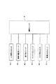
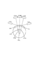
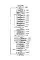
図1は、本発明にかかる自走式掃除機の概略構成をブロック図により示している。
同図に示すように、各ユニットを制御する制御ユニット10と、周囲に人間がいるか否かを検知する人体感知ユニット20と、周囲の障害物を検知するための障害物監視ユニット30と、移動を実現する走行系ユニット40と、掃除を行うためのクリーナ系ユニット50と、所定範囲を撮影するカメラ系ユニット60と、無線でLANに接続するための無線LANユニット70とから構成されている。なお、本体BDは薄型の略円筒形状をなしている。
FIG. 1 is a block diagram showing a schematic configuration of a self-propelled cleaner according to the present invention.
As shown in the figure, a
図2は、各ユニットを具体的に実現する電気系の構成をブロック図により示している。 制御ユニット10として、CPU11と、ROM13と、RAM12がバス14を介して接続されている。CPU11は、ROM13に記録されている制御用プログラムおよび各種パラメータテーブルに従い、RAM12をワークエリアとして使用して各種の制御を実行する。上記制御用プログラムの内容については後述する。
FIG. 2 is a block diagram showing the configuration of an electric system that specifically realizes each unit. As the
また、バス14には操作パネルユニット15が備えられ、同操作パネルユニット15には、各種の操作用スイッチ15aと、液晶表示パネル15bと、表示用LED15cが備えられている。液晶表示パネルは多階調表示が可能なモノクロ液晶パネルを使用しているが、カラー液晶パネルなどを使用することも可能である。
The
本自走式掃除機はバッテリー17を有しており、CPU11はバッテリ監視回路16を介してバッテリー17の残量をモニター可能となっている。なお、同バッテリー17は誘導コイル18aを介して非接触で供給される電力を用いて充電する充電回路18を備えている。バッテリー監視回路16は主にバッテリー17の電圧を監視して残量を検知する。 人体感知ユニット20として、四つの人体センサ21(21fr,21rr,21fl,21rl)が前方左右斜め方向と後方左右斜め方向に対面させて備えられている。各人体センサ21は赤外線の受光センサを備えるとともに受光した赤外線の光量の変化に基づいて人体の有無を検知するものであり、変化する赤外線照射物体を検知したとき出力用のステータスを変化させるため、CPU11は上記バス14を介して同人体センサ21の検知を取得することが可能となっている。すなわち、CPU11は所定時間毎に各人体センサ21fr,21rr,21fl,21rlのステータスを取得しにいき、取得したステータスが変化していれば、同人体センサ21fr,21rr,21fl,21rlの対向方向に人体の存在を検知することが可能となる。
This self-propelled cleaner has a battery 17, and the
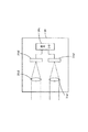
ここでは赤外線の光量変化に基づくセンサによって人体センサを構成しているが、人体センサはこれに限られるものではない。例えば、CPUの処理量が上がればカラー画像を撮影し、人体に特徴的な肌色の領域を探し、同領域の大きさ、変化に基づいて人体を検知するという構成を実現することもできる。むろん、モノクロ画像を撮影し、画像の変化に基づいて動体を検出するモーションセンサを実現しても良い。 Here, the human body sensor is configured by a sensor based on a change in the amount of infrared light, but the human body sensor is not limited to this. For example, if the processing amount of the CPU increases, a configuration can be realized in which a color image is taken, a skin color region characteristic of the human body is searched, and the human body is detected based on the size and change of the region. Of course, a motion sensor that captures a monochrome image and detects a moving object based on a change in the image may be realized.
障害物監視ユニット30は、オートフォーカス(以下、AFと呼ぶ。)用測距センサとしてのAF用パッシブセンサ31(31R,31FR,31FM,31FL,31L,31CL))とその通信用インターフェイスであるAFセンサ通信I/O32と、照明用LED33と、各LEDに駆動電流を供給するLEDドライバ34とから構成されている。まず、AF用パッシブセンサ31の構成について説明する。図3はAF用パッシブセンサ31の概略構成を示している。二軸のほぼ平行な光学系31a1,31a2と、同光学系31a1,31a2の結像位置にほぼそれぞれ配設されたCCDラインセンサ31b1,31b2と、各CCDラインセンサ31b1,31b2の撮像イメージデータを外部に出力するための出力I/O31cとを備えている。
The
CCDラインセンサ31b1,31b2は160〜170画素のCCDセンサを有しており、各画素ごとに光量を表す8ビットのデータを出力可能となっている。光学系が二軸であるので、結像イメージには距離に応じたずれが生じており、それぞれのCCDラインセンサ31b1,31b2が出力するデータのずれに基づいて距離を計測できる。例えば、近距離になるほど結像イメージのずれが大きく、遠距離になるほど結像イメージのずれはなくなっていく。従って、一方の出力データにおける4〜5画素毎のデータ列を画報の出力データ中でスキャンし、元のデータ列のアドレスと発見されたデータ列のアドレスとの相違を求め、相違量で予め用意しておいた相違量−距離変換テーブルを参照し、実際の距離を求めることになる。 The CCD line sensors 31b1 and 31b2 have a CCD sensor of 160 to 170 pixels, and can output 8-bit data representing the amount of light for each pixel. Since the optical system is biaxial, the imaged image has a shift corresponding to the distance, and the distance can be measured based on the shift of data output from the CCD line sensors 31b1 and 31b2. For example, the shift of the image is larger as the distance is shorter, and the shift of the image is eliminated as the distance is longer. Therefore, the data string for every 4 to 5 pixels in one output data is scanned in the output data of the image report, and the difference between the address of the original data string and the address of the discovered data string is obtained. The actual distance is obtained by referring to the prepared difference amount-distance conversion table.
AF用パッシブセンサ31R,31FR,31FM,31FL,31L,31CLのうち、AF用パッシブセンサ31FR,31FM,31FLは正面の障害を検知するために利用され、AF用パッシブセンサ31R,31Lは前方左右直前の障害を検知するために利用され、AF用パッシブセンサ31CLは前方天井までの距離を検知するために利用されている。
Of the AF
図4は正面と前方左右直前の障害をAF用パッシブセンサ31で検知する際の原理を示している。これらのAF用パッシブセンサ31は周囲の床面に対して斜めに向けて配置されている。対向方向に障害物が無い場合、AF用パッシブセンサ31による測距距離はほぼ全撮像範囲においてL1となる。しかし、図面で一点鎖線で示すように段差がある場合、その測距距離はL2となる。測距距離が伸びたら下がる段差があると判断できる。また、二点鎖線で示すように上がる段差があれば測距距離はL3となる。障害物があるときも上がる段差と同様に測距距離は同障害物までの距離として計測され、床面よりも短くなる。
FIG. 4 shows the principle for detecting an obstacle immediately before the front and left and right with the AF
本実施形態においては、AF用パッシブセンサ31を前方の床面に斜めに配向した場合、その撮像範囲は約10cmとなった。本自走式クリーナの幅が30cmであったので、三つのAF用パッシブセンサ31FR,31FM,31FLについては撮像範囲が重ならないように僅かに角度を変えて配置している。これにより、三つのAF用パッシブセンサ31FR,31FM,31FLにより前方方向の30cmの範囲での障害物と段差を検知できるようになっている。むろん、検知幅はセンサの仕様や取付位置などに応じて変化し、実際に必要となる幅に応じた数のセンサを利用すればよい。
In the present embodiment, when the AF
一方、前方左右直前の障害を検知するAF用パッシブセンサ31R,31Lについては撮像範囲を垂直方向を基準として床面に対して斜めに配置している。また、AF用パッシブセンサ31Rを本体左方に取り付けつつ本体中央を横切って右方直前位置から本体幅を超えた右方の範囲を撮像するように対向させてあり、AF用パッシブセンサ31Lを本体右方に取り付けつつ本体中央を横切って左方直前位置から本体幅を超えた左方の範囲を撮像するように対向させてある。
On the other hand, the AF
クロスさせないで左右の直前位置を撮影するようにすると、センサは急角度で床面に対面させなければならず、このようにすると撮像範囲が極めて狭くなってしまうので、複数のセンサが必要となる。このため、敢えてクロスさせる配置とし、撮像範囲を広げて少ない数のセンサで必要範囲をカバーできるようにしている。また、撮像範囲を垂直方向を基準として斜めに配置するのは、CCDラインセンサの並び方向が垂直方向に向くことを意味しており、図5に示すように撮像できる幅がW1となる。ここで、撮像範囲の右側で床面までの距離L4は短く、左側で距離L5が長くなっている。本体BDの側面の境界ラインが図面上の波線位置Bであると、境界ラインまでの撮像範囲は段差の検知などに利用され、境界ラインを超える撮像範囲は壁面の有無を検知するために利用される。 If the left and right positions are photographed without crossing, the sensor must face the floor surface at a steep angle, and in this case, the imaging range becomes extremely narrow, so a plurality of sensors are required. . For this reason, the arrangement is made to cross, and the imaging range is widened so that the required range can be covered with a small number of sensors. Further, arranging the imaging range obliquely with respect to the vertical direction means that the arrangement direction of the CCD line sensors is directed in the vertical direction, and the width capable of imaging is W1, as shown in FIG. Here, the distance L4 to the floor surface is short on the right side of the imaging range, and the distance L5 is long on the left side. If the boundary line on the side surface of the main body BD is a wavy position B on the drawing, the imaging range up to the boundary line is used for detecting a step, and the imaging range exceeding the boundary line is used for detecting the presence or absence of a wall surface. The
前方天井までの距離を検知するAF用パッシブセンサ31CLは天井に対面している。通常はAF用パッシブセンサ31CLが検知する床面から天井までの距離が一定であるが、壁面に近づいてくると撮像範囲が天井ではなく壁面となるので、測距距離が短くなってくる。従って、前方壁面の存在をより正確に検知できる The AF passive sensor 31CL that detects the distance to the front ceiling faces the ceiling. Normally, the distance from the floor surface to the ceiling detected by the AF passive sensor 31CL is constant, but when approaching the wall surface, the imaging range becomes the wall surface instead of the ceiling, and the distance measurement distance becomes shorter. Therefore, the presence of the front wall surface can be detected more accurately.
図6は各AF用パッシブセンサ31R,31FR,31FM,31FL,31L,31CLの本体BDへの取り付け位置を示すとともに、それぞれの床面での撮像範囲を括弧付きの符号で対応させて示している。なお、天井については撮像範囲は省略している。
FIG. 6 shows the attachment positions of the AF
AF用パッシブセンサ31R,31FR,31FM,31FL,31Lの撮像を証明するように白色LEDからなる右照明用LED33Rと、左照明用LED33Lと、前照明用LED33Mを備えており、LEDドライバ34はCPU11からの制御指示に基づいて駆動電流を供給して照明できるようになっている。これにより、夜間であったり、テーブルの下などの暗い場所でもAF用パッシブセンサ31から有効な撮像イメージのデータを得ることができるようになる。
In order to prove the imaging of the AF
走行系ユニット40は、モータドライバ41R,41Lと、駆動輪モータ42R,42Lと、この駆動輪モータ42R,42Lにて駆動される図示しないギアユニットと駆動輪を備えている。駆動輪は本体BDの左右に一輪ずつ配置されており、この他に駆動源を持たない自由転動輪が本体の前方側中央下面に取り付けられている。駆動輪モータ42R,42Lは回転方向と回転角度をモータドライバ41R,41Lによって詳細に駆動可能であり、各モータドライバ41R,41LはCPU11からの制御指示に応じて対応する駆動信号を出力する。また、駆動輪モータ42R,42Lと一体的に取り付けられているロータリーエンコーダの出力から現実の駆動輪の回転方向と回転角度が正確に検知できるようになっている。なお、ロータリーエンコーダは駆動輪と直結させず、駆動輪の近傍に自由回転可能な従動輪を取り付け、同従動輪の回転量をフィードバックさせることによって駆動輪にスリップが生じているような場合でも現実の回転量を検知できるようにしても良い。走行系ユニット40には、この他に地磁気センサ43が備えられており、地磁気に照らし合わせて走行方向を判断できるようになっている。また、加速度センサ44はXYZ三軸方向における加速度を検知し、検知結果を出力する。
The
なお、本自走式掃除機においては、自ずから駆動輪の負担が大きいので、十分な性能を長期にわたって維持できるように、駆動輪ユニットとして交換可能に構成してある。具体的には、左右のそれぞれで駆動輪モータ42R,42Lとギアユニットと駆動輪とが本体BDから着脱可能なように一体化して形成してある。
In addition, in this self-propelled cleaner, since the load of the drive wheel is naturally large, the drive wheel unit is configured to be replaceable so that sufficient performance can be maintained over a long period of time. Specifically, the
ギアユニットや駆動輪は各種のものを採用可能であり、円形のゴム製タイヤを駆動させるようにしたり、無端ベルトを駆動させるようにして実現しても良い。 Various types of gear units and drive wheels can be employed, and may be realized by driving a circular rubber tire or driving an endless belt.
本自走式掃除機における掃除機構は、前方両サイドに配置されて本体BDの進行方向における両側寄りのゴミなどを当該本体BDにおける中央付近にかき寄せるサイドブラシと、本体の中央付近にかき寄せられたゴミをすくい上げるメインブラシと、同メインブラシによりすく上げられるゴミを吸引してダストボックス内に収容する吸引ファンとから構成されている。クリーナ系ユニット50は、各ブラシを駆動するサイドブラシモータ51R,51Lとメインブラシモータ52、それぞれのモータに駆動電力を供給するモータドライバ53R,53L,54と、吸引ファンを駆動する吸引モータ55と、同吸引モータに駆動電力を供給するモータドライバ56とから構成されている。サイドブラシやメインブラシを使用した掃除は床面の状況やバッテリーの状況やユーザの指示などに応じてCPU11が適宜判断して制御するようにしている。
The cleaning mechanism in the self-propelled cleaner is arranged on both front sides and scrapes dust near the both sides in the traveling direction of the main body BD to the vicinity of the center of the main body BD, and the vicinity of the center of the main body. The main brush scoops up the dust and a suction fan that sucks up the dust scooped up by the main brush and stores it in the dust box. The
カメラ系ユニット60は、それぞれ視野角の異なる二つのCMOSカメラ61,62を備えており、本体BDの正面方向であってそれぞれことなる仰角にセットされている。また、各カメラ61,62への撮像を指示するとともに撮像イメージを出力するためのカメラ通信I/O63も備えられている。さらに、カメラ61,62の撮像方向に対面させて15コの白色LEDからなるカメラ用照明LED64と、同LEDに照明用駆動電力を供給するためのLEDドライバ65を備えている。
The
無線LANユニット70は、無線LANモジュール71を有しており、CPU11は所定のプロトコルに従って外部LANと無線によって接続可能となっている。無線LANモジュール71は、図示しないアクセスポイントの存在を前提として、同アクセスポイントはルータなどを介して外部の広域ネットワーク(例えばインターネット)に接続可能な環境となっていることとする。従って、インターネットを介した通常のメールの送受信やWEBサイトの閲覧といったことが可能である。なお、無線LANモジュール71は、規格化されたカードスロットと、同スロットに接続される規格化された無線LANカードなどから構成されている。むろん、カードスロットは他の規格化されたフラッシュカードを接続することも可能である。
The
次に、上記構成からなる自走式掃除機の動作について説明する。
(1)走行制御及び清掃動作について
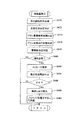
図7及び図8は上記CPU11が実行する制御プログラムに対応したフローチャートを示しており、図9は同制御プログラムに従って本自走式掃除機が走行する走行順路を示す図である。
電源オンにより、CPU11は図7の走行制御を開始する。ステップS110ではAF用パッシブセンサ31の検知結果を入力し、前方エリアを監視する。前方エリアの監視に使用するのはAF用パッシブセンサ31FR,31FM,31FLの検知結果であり、平坦な床面であれば、その撮像イメージから得られるのは図4に示す斜め下方の床面までの距離L1である。それぞれのAF用パッシブセンサ31FR,31FM,31FLの検知結果に基づき、本体BD幅に一致する前方の床面が平坦であるか否かが判断できる。ただし、この時点では、各AF用パッシブセンサ31FR,31FM,31FLが対面している床位置と本体の直前位置までの間の情報は何も得られていないので死角となる。
Next, the operation of the self-propelled cleaner having the above configuration will be described.
(1) Traveling Control and Cleaning Operation FIGS. 7 and 8 show flowcharts corresponding to the control program executed by the
When the power is turned on, the
ステップS120ではモータドライバ41R,41Lを介して駆動輪モータ42R,42Lに対してそれぞれ回転方向を異にしつつ同回転量の駆動を指示する。これにより本体BDはその場で回転を始める。同じ場所での360度の回転(スピンターン)に要する駆動モータ42R,42Lの回転量は予め分かっており、CPU11は同回転量をモータドライバ41R,41Lに指示している。
In step S120, the
スピンターン中、CPU11はAF用パッシブセンサ31R,31Lの検知結果を入力し、本体BDの直前位置の状況を判断する。上述した死角はこの間の検知結果により、ほぼなくなり、段差、障害物が何も無い場合、周囲の平坦な床面の存在を検知できる。
ステップS130ではCPU11はモータドライバ41R,41Lを介して駆動輪モータ42R,42Lに対してそれぞれ同回転量の駆動を指示する。これにより本体BDは直進を開始する。直進中、CPU11はAF用パッシブセンサ31FR,31FM,31FLの検知結果を入力し、正面に障害物がいないか判断しながら前進する。そして、同検知結果から正面に障害物たる壁面が検知できたら、その壁面の所定距離だけ手前で停止する。
During the spin turn, the
In step S130, the
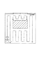
ステップS140では右に90度回転する。ステップS130で壁面の所定距離だけ手前で停止したが、この所定距離は本体BDが回転動作するときに同壁面に衝突せず、また、直前および左右の状況を判断するためのAF用パッシブセンサ31R,31Lが検知する本体幅の外側にあたる範囲の距離である。すなわち、ステップS130にてAF用パッシブセンサ31FR,31FM,31FLの検知結果に基づいて停止し、ステップS140にて90度回転するときには、少なくともAF用パッシブセンサ31Lが壁面の位置を検知できる程度の距離となるようにしている。また、90度回転するときには、上記AF用パッシブセンサ31R,31Lの検知結果に基づいて直前位置の状況を判断しておく。図9はこのようにしてたどり着いた平面図で見たときの部屋の左下角を清掃開始位置として清掃走行を開始する状況を示している。
In step S140, it is rotated 90 degrees to the right. In step S130, the actuator stops at a predetermined distance on the wall surface, but this predetermined distance does not collide with the wall surface when the main body BD rotates, and the AF
清掃走行開始位置へたどり着く方法はこれ以外にも各種の方法がある。壁面に当接する状況において右に90度回転するだけでは、最初の壁面の途中から始めることになることもあるため、図9に示すように左下角の最適位置にたどり着くのであれば、壁面に当接して左90度回転し、正面の壁面に当接するまで前進し、当接した時点で180度回転することも望ましい走行制御である。 There are various other methods for reaching the cleaning travel start position. If you rotate 90 degrees to the right while in contact with the wall surface, it may start from the middle of the first wall surface, so if you reach the optimal position in the lower left corner, as shown in FIG. It is also desirable travel control to rotate 90 degrees to the left, move forward until it contacts the front wall surface, and rotate 180 degrees when contacted.
ステップS150では、清掃走行を実施する。同清掃走行のより詳細なフローを図8に示している。前進走行するにあたり、ステップS210〜S240にて各種のセンサの検知結果を入力している。ステップS210では前方監視センサデータ入力しており、具体的にはAF用パッシブセンサ31FR,31FM,31FL,31CLの検知結果を入力し、走行範囲の前方に障害物あるいは壁面が存在しないか否かの判断に供することになる。なお、前方監視という場合には、広い意味での天井の監視も含めている。 In step S150, cleaning travel is performed. A more detailed flow of the cleaning traveling is shown in FIG. When traveling forward, detection results of various sensors are input in steps S210 to S240. In step S210, forward monitoring sensor data is input. Specifically, detection results of AF passive sensors 31FR, 31FM, 31FL, and 31CL are input, and whether or not an obstacle or a wall surface exists in front of the traveling range. It will be used for judgment. In addition, in the case of forward monitoring, monitoring of the ceiling in a broad sense is included.
ステップS220では段差センサデータ入力をしており、具体的にはAF用パッシブセンサ31R,31Lの検知結果を入力し、走行範囲の直前位置に段差がないか否かの判断に供することになる。また、壁面や障害物に沿って平行に移動するときには壁面や障害物までの距離を計測し、平行に移動しているか否かの判断に供することになる。
In step S220, step sensor data is input. Specifically, the detection results of the AF
ステップS230では地磁気センサデータ入力をしており、具体的には地磁気センサ43の検知結果を入力し、直進走行中に走行方向が変化していないか否かを判断するのに利用する。例えば、清掃走行開始時の地磁気の角度を記憶しておき、走行中に検出される角度が記憶されている角度と異なった場合には、左右の駆動輪モータ42R,42Lの回転量をわずかに異ならせて進行方向を修正し、元の角度へ戻す。例えば、地磁気の角度に基づいて角度が増加する方向へ変化(359度から0度への変化は例外点となる))したら左方向へ軌道を修正する必要があり、右の駆動輪モータ42Rの回転量を左の駆動輪モータ42Lの回転量よりも僅かに増やすようにそれぞれのモータドライバ41R,41Lへ駆動を制御する指示を出力する。
In step S230, geomagnetic sensor data is input. Specifically, the detection result of the
ステップS240では、加速度センサデータ入力をしており、具体的には加速度センサ44の検知結果を入力し、走行状態の確認に供することになる。例えば、直進走行開始時に概ね一定の方向への加速度を検知できれば正常な走行と判断できるが、回転する加速度を検知すれば片方の駆動輪モータが駆動されていないような異常を判断できる。また、正常な範囲の加速度値を超えたら段差などから落下したり、横転したような異常を判断できる。そして、前進中に後方にあたる方向への大きな加速度を検知したら前方の障害物に当接した異常を判断できる。このように、加速度値を入力して目標加速度を維持するとか、その積分値に基づいて速度を得るというような走行に対する直接的な制御をすることはないが、異常検出の目的として加速度値を有効に利用している。
In step S240, acceleration sensor data is input. Specifically, the detection result of the
ステップS250では、ステップS210とステップS220で入力したAF用パッシブセンサ31FR,31FM,31CL,31FL,31R,31Lの検知結果に基づいて障害物の判定を行う。障害物の判定は、正面、天井、直前のそれぞれの部位毎に行う。正面は障害物あるいは壁面の意味として判定し、直前は段差の判定とともに走行範囲外の左右の状況、例えば壁面の有無などを判定する。天井は鴨居などによって天井までの距離が下がってきているときに正面に障害物がないとしても、そこからは廊下であって室外に出てしまうことを判定するのに利用される。 In step S250, the obstacle is determined based on the detection results of the AF passive sensors 31FR, 31FM, 31CL, 31FL, 31R, and 31L input in steps S210 and S220. Obstacles are determined for each of the front, ceiling, and immediately preceding parts. The front is determined as the meaning of an obstacle or a wall, and immediately before the step is determined, the right and left conditions outside the traveling range, for example, the presence or absence of a wall are determined. Even if there is no obstacle in the front when the distance to the ceiling is decreasing due to a duck or the like, the ceiling is used to determine that it is a corridor and goes out of the room.
ステップS260では、各センサからの検知結果を総合的に判断し、回避の必要があるか否かを判断する。回避の必要がない限りステップS270の清掃処理を実行する。清掃処理は、サイドブラシとメインブラシを回転させつつ、ゴミを吸引する処理であり、具体的にはモータドライバ53R,53L,54,56に各モータ51R,51L,52,55を駆動させる指示を出力する。むろん、走行中は常に同指示を出しているのであり、後述するように清掃走行の終端条件が成立したときに停止させることになる。
In step S260, the detection result from each sensor is comprehensively determined to determine whether or not it is necessary to avoid it. Unless there is a need for avoidance, the cleaning process in step S270 is executed. The cleaning process is a process of sucking dust while rotating the side brush and the main brush. Specifically, the
なお、この清掃処理を実施している間、経過時間と、走行距離を累積する。経過時間は、上記モータドライバ53R,53L,54,56に対して駆動指示を出力した時間と、停止させる指示を出した時間とをログとして所定の不揮発性の記憶領域に記録していく処理となる。これだけでは直接の累積時間を計測することにはならないが、累積時間を参照する時点で同ログを参照していって累積時間を計算する。むろん、ログを出力する毎にその時点での累積時間を更新することも可能である。走行距離の累積は、ロータリーエンコーダの出力に基づいて積算していく。ロータリーエンコーダの出力はログとして記憶するにはデータが多すぎるので、出力を得られる毎に累積していく。前進も後進もそれぞれ同様に移動距離を累積する。これらの累積使用時間と累積走行距離は、サイドブラシやメインブラシの使用の程度の目安として後に利用することになる。
During the cleaning process, the elapsed time and the travel distance are accumulated. The elapsed time is a process of recording the time when the drive instruction is output to the
一方、回避が必要と判断されると、ステップS280にて右に90度ターンを実施する。このターンは同じ位置での90度ターンであり、モータドライバ41R,41Lを介して駆動輪モータ42R,42Lに対してそれぞれ回転方向を異にしつつ90度ターンに必要なだけの回転量の駆動を指示する。回転方向は右の駆動輪に対して後退の方向であり、左の駆動輪に対して前進の方向となる。回転中は段差センサであるAF用パッシブセンサ31R,31Lの検知結果を入力し、障害物の状況を判断する。例えば、正面に障害を検知し、右90度ターンを実施したとき、AF用パッシブセンサ31Rが前方右方の直前位置に壁面を検知しなければ単に正面の壁面に当接したといえるが、回転後も前方右方の直前位置に壁面を検知しているのであれば、角部に入り込んでいるといったことが判断できる。また、右90度回転時にAF用パッシブセンサ31R,31Lのいずれもが前方直前に障害を検知しなければ、壁面に当接したのではなく、小さな障害物などであったと判断できる。
On the other hand, if it is determined that avoidance is necessary, a 90 degree turn to the right is performed in step S280. This turn is a 90-degree turn at the same position, and drives the rotation amount necessary for the 90-degree turn while changing the rotation direction with respect to the
ステップS290では障害物を走査しながらの進路変更のため前進する。壁面に当接し、右90度回転後、前進していく。壁面の手前で停止したのであれば、前進の走行量は概ね本体BDの幅分である。その分の前進後、ステップS300では再度右90度ターンを実施する。 In step S290, the vehicle advances to change the course while scanning the obstacle. It abuts against the wall and rotates forward 90 degrees to the right. If stopped before the wall surface, the forward travel amount is approximately the width of the main body BD. After advance by that amount, in step S300, the right 90 degree turn is performed again.
以上の移動の間、正面の障害物、前方左右の障害物の有無は常に走査して状況を確認しており、部屋の中の障害物の有無の情報として記憶していく。
ところで、上述した説明では、右90度ターンを2度実行したが、次に前方に壁面を検知した時点で右90度ターンを実行すると元に戻ってしまうので、二度の90度ターンは、右を繰り返したら、次は左を繰り返し、その次は右というように交互に行っていく。従って、奇数回目の障害物回避では右ターン、偶数回目の障害物回避では左ターンとなる。 以上のように障害物を回避しながら、部屋の中をつづら折り状に走査して清掃走行を継続していく。そして、部屋の終端にきたか否かをステップS310にて判断する。清掃走行の終端は、二度目のターン後に、壁面に沿って前進して清掃走行を実施し、その後で前方に障害物を検知した場合と、既に走行した部位に入り込んだ場合である。すなわち、前者hつづれ折り状に走行していった最後の端から端への走行後に生じる終了条件であり、後者は後述するように未清掃エリアを発見して再度清掃走行を開始したときの終了条件になる。
During the above movement, the presence or absence of front obstacles and front and right obstacles is always scanned to check the situation and stored as information on the presence or absence of obstacles in the room.
By the way, in the above description, the right 90 degree turn is executed twice. However, when the right 90 degree turn is executed next when the wall surface is detected forward, the turn returns to the original state. If you repeat the right, the next is the left, the next is the right, and so on. Therefore, a right turn is used for the odd-numbered obstacle avoidance and a left turn is used for the even-numbered obstacle avoidance. As described above, the cleaning traveling is continued by scanning the room in a zigzag manner while avoiding the obstacles. Then, in step S310, it is determined whether or not the end of the room has been reached. The end of the cleaning travel is when the second turn is advanced along the wall surface to perform the cleaning travel, after which an obstacle is detected forward and when the vehicle has already traveled. In other words, the former is an end condition that occurs after the last end-to-end travel that traveled in a folded manner, and the latter ends when an uncleaned area is found and cleaning travel is started again as will be described later. It becomes a condition.
この終端条件が成立していなければ、ステップS210へ戻って以上の処理を繰り返す。終端条件が成立していれば、本清掃走行のサブルーチン処理を終了し、図7に示す処理へ復帰する。
復帰後、ステップS160では、これまでの走行経路と走行経路の周囲の状況から未清掃エリアが残っていないか判断する。未清掃エリアの有無の判断は公知の各種の手法を利用可能であり、一例としてこれまでの走行経路をマッピングして記憶していく手法を利用可能である。この例では、上述したロータリーエンコーダの検知結果に基づいて室内での走行経路と、走行中に検出した壁面の有無を記憶領域に確保指定あるマップ上に書き込んでいっており、周囲の壁面が途絶えることなく連続し、かつ、室内の存在していた障害物の周囲も連続し、かつ、室内で障害物を除く範囲を全て走行したか否かで判断する。未清掃エリアが見つかれば、ステップS170で未清掃エリアの開始点へと移動し、ステップS150に戻って清掃走行を再開する。
If this termination condition is not satisfied, the process returns to step S210 and the above processing is repeated. If the termination condition is satisfied, the subroutine process of the main cleaning traveling is terminated and the process returns to the process shown in FIG.
After returning, in step S160, it is determined whether or not an uncleaned area remains from the previous travel route and the situation around the travel route. Various known methods can be used to determine whether or not there is an uncleaned area. For example, a method of mapping and storing a travel route so far can be used. In this example, based on the detection result of the rotary encoder described above, the indoor travel route and the presence / absence of the wall surface detected during the travel are written on a map designated to be secured in the storage area, and the surrounding wall surface is interrupted. It is determined whether or not the vehicle is running continuously, and the surroundings of obstacles that existed in the room are also continuous, and the entire range excluding the obstacles has been traveled. If an uncleaned area is found, it moves to the starting point of an uncleaned area at step S170, returns to step S150, and restarts cleaning travel.
未清掃エリアが複数箇所に散在していたとしても、上述したような清掃走行の終端条件が成立するごとに、未清掃エリアの検出を繰り返していくことにより、最終的には未清掃エリアがなくなる。
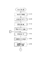
(2)自己診断機能について
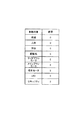
図10はCPU11が実施する自己診断処理のフローチャートであり、図11は診断結果をフラグとして書き込む診断結果フラグテーブルを示す図である。
自己診断処理は、ユーザが本体BDを壁面の傍に設置して電源をオンにすることから始まる。
CPU11は、まず、ステップS400にて電源オンの直後か否かを判断する。自己診断の処理は電源をオンにした後で一度実行すれば十分であるから、ステップS400は以下の処理を二度繰り返さないための判断である。例えば、以下の処理を実施したときには所定のフラグをセットするものとし、このフラグがセットされてなければ初めての起動であると判断して以下の処理を実行する。ステップS401にて診断結果フラグテーブルを初期化する。すなわち、テーブル内容として初期値の”0”を書き込む。
Even if the uncleaned areas are scattered in a plurality of places, the uncleaned areas are finally eliminated by repeating the detection of the uncleaned areas every time the termination condition of the cleaning traveling as described above is satisfied. .
(2) Self-diagnosis function FIG. 10 is a flowchart of the self-diagnosis process performed by the
The self-diagnosis process starts when the user installs the main body BD near the wall surface and turns on the power.
The
ステップS402では、駆動輪モータへ360度のスピンターンを指示する。具体的にはモータドライバ41R,41Lに対してそれぞれ回転方向を異にして360度回転するために必要な回転量を指示し、同モータドライバ41R,41Lが駆動輪モータ42R,42Lに対して駆動電力を出力する。この指示によって本体BDが360度回転する間に、CPU11はステップS404〜S414の処理を繰り返し実施する。
In step S402, a 360-degree spin turn is instructed to the drive wheel motor. Specifically, the
まず、ステップS404では、各センサの検知結果を入力する。そして、ステップS406では、側壁検出の診断処理を実行する。側方の障害物の有無を検出する側方センサは、AF用パッシブセンサ31R,31FR,31FM,31FL,31L,31CLが該当する。むろん、これらは本体BDにおける側面のみならず正面及び天井の測距距離を含んでいるが、これらは本体BDの周囲に壁面があるか否かを検出するために利用されているので、広い意味で側方の障害物の有無の検知に利用可能である。360度回転する間にAF用パッシブセンサ31R,31FR,31FM,31FL,31L,31CLの検知出力を得て、それぞれが壁面の傍で本体BDが回転する際に予想されうる変化をすれば異常なしと判断できる。しかし、壁面の検出を全くしない場合には異常ありと判断できる。例えば、正面のAF用パッシブセンサ31FR,31FM,31FLであれば、一回転する間に必ず隣接する壁面と対面するはずであり、このときの測距距離は本来の床面よりも近い距離となる。また、段差センサとしても使用するAF用パッシブセンサ31R,31Lについては、一回転する間に全範囲が床面の場合と、一部に壁面を検出する測距距離が得られるはずである。前方の天井に対面するAF用パッシブセンサ31CLについては、本体BDが壁面に対面するときに壁面の上方部位に対面し、反対に対面するときに天井に対面するので一回転する間に測距距離は変化する。これらの変化の有無によってセンサ(側方センサ)の検知結果に異常がないか判断できる。
First, in step S404, the detection result of each sensor is input. In step S406, sidewall detection diagnosis processing is executed. The side sensors that detect the presence or absence of side obstacles correspond to AF
ステップS408では人体検出の診断処理を実施する。すなわち、人体センサ21fr,21rr,21fl,21rlの異常を診断する。ユーザが本体BDを壁面そばに置いて電源をオンにしているので、本体BDが一回転する間に各人体センサ21fr,21rr,21fl,21rlは一度ずつユーザに対面することになり、人体を検知した結果を出力するはずである。一回転の間に一回もユーザを検知した結果を出力しなければ異常と診断できる。 In step S408, a human body detection diagnosis process is performed. That is, the abnormality of the human body sensors 21fr, 21rr, 21fl, 21rl is diagnosed. Since the user places the main body BD near the wall surface and turns on the power, each human body sensor 21fr, 21rr, 21fl, 21rl faces the user once and detects the human body while the main body BD rotates once. Should output the result. An abnormality can be diagnosed if the result of detecting the user is not output once during one rotation.
ステップS410では方位検出の診断処理を実施する。本体BDには方位を検知するための地磁気センサ43が備えられており、本体BDが一回転する間に地磁気も一回転するはずである。地磁気の検知結果が360度変化しなければ異常と判断できる。
ステップS411では加速度センサ44の診断処理を実施する。加速度センサ44を本体BDの回転軸芯に一致させていない限り本体BDが一回転する間に加速度センサ44はXY方向における加速度を検知するはずである。XY方向の検知結果が得られなければ異常と判断できる。
In step S410, a direction detection diagnosis process is performed. The main body BD is provided with a
In step S411, the
ステップS412では回転動作の診断処理を実施する。上述したように駆動輪モータ42R,42Lには一体的にロータリーエンコーダが出力されており、回転動作を指示しているのでそのエンコード出力も徐々に変化しているはずである。一方、回転動作を指示しているのにエンコード出力が変化していなければロータリーエンコーダか駆動輪ユニットの異常と判断できる。
In step S412, a rotational motion diagnosis process is performed. As described above, the rotary encoders are integrally output to the
ステップS414では、360度の回転が終了するまで上記診断を繰り返すための判定を実施している。
このように360度スピンターンという一つの動作に基づき、上述したような広義の側方センサと方位センサとロータリーエンコーダの検知機能の診断を実施できる。
続いて、ステップS416ではユーザに本体BDを持ち上げるように液晶表示パネル15b上でメッセージを表示する。その直後、ステップS418にて段差検出の診断処理を実施する。段差センサはAF用パッシブセンサ31R,31Lが該当し、ユーザが本体を持ち上げることでAF用パッシブセンサ31R,31Lの撮影範囲に本来の床面よりも遠い測距距離が得られることになる。また、ステップS419では加速度センサ44の診断処理を実施する。本体BDを持ち上げれば、加速度センサ44はZ軸方向の検知結果を出力するはずである。Z軸方向の検知結果が得られなければ異常と判断できる。
なお、ステップS420では一定の時間ステップS418,S419の診断を繰り返すためにタイムアップしたか否かの判断を行っている。
以上で駆動機構における基本性能の診断処理が完了する。
In step S414, the determination for repeating the diagnosis is performed until the rotation of 360 degrees is completed.
As described above, based on one operation of 360-degree spin turn, it is possible to diagnose the detection functions of the side sensor, the azimuth sensor, and the rotary encoder in the broad sense as described above.
In step S416, a message is displayed on the liquid
In step S420, it is determined whether or not the time is up in order to repeat the diagnosis in steps S418 and S419 for a certain period of time.
This completes the basic performance diagnosis process in the drive mechanism.
次に、ステップS422〜S426の処理で掃除機構に利用される各種のモータの診断を実施する。ここでは、以下のモータに対して回転を検出するためのFGパルス発生器が備えられているものとする。ステップS422ではサイドブラシモータ51R,51Lの診断を行うため、モータドライバ53R,53Lに対して駆動を指示し、図示しないFGパルス発生器の出力状況を入力する。回転を指示しているにもかかわらず、FGパルスが出力されない場合は回転していないので、異常と判断できる。ステップS424におけるメインブラシモータの動作診断処理と、ステップS426における吸引モータ動作診断処理も全く同様に行われ、モータドライバ54とモータドライバ56に対して回転を指示し、メインブラシモータ52と吸引モータ55に備えられたFGパルス発生器の出力状況を入力して異常の有無を判断する。
Next, diagnosis of various motors used for the cleaning mechanism is performed in the processes of steps S422 to S426. Here, it is assumed that an FG pulse generator for detecting rotation is provided for the following motors. In step S422, in order to diagnose the
ステップS428では、LED発光の診断処理を実施する。各LEDドライバ34,65にLEDの点灯を指示し、その際のバッテリーの電圧降下をみて点灯しているか否かを判断する。
なお、このときに各LEDの点滅に対応してバッテリーの電圧降下が生じるか否かにより、LED自体の診断を行なうが、各種のモータやLEDを駆動しない状態でのバッテリーの電圧も計測する。むろん、消耗時の電圧を計測してもバッテリーの診断にはならないので、充電完了時にフラグを設定するようにしておき、フラグがオンとなっているときに電圧を計測する。この満充電時の電圧によってバッテリーの消耗度合いを計測する。なお、充電回数を計数しておき、予定しておいた充電回数を超えた時点で消耗したと判断するようにしてもよい。
In step S428, a diagnosis process for LED emission is performed. The
At this time, the LED itself is diagnosed depending on whether or not the battery voltage drop occurs in response to the blinking of each LED, but the voltage of the battery in a state where various motors and LEDs are not driven is also measured. Of course, since the battery is not diagnosed even if the voltage at the time of consumption is measured, a flag is set when charging is completed, and the voltage is measured when the flag is on. The degree of battery consumption is measured based on the voltage when fully charged. Note that the number of times of charging may be counted, and it may be determined that the battery has been consumed when the number of times of charging has been exceeded.
ステップS430では、セキュリティ機能に関する診断処理を実施する。本実施例においては、セキュリティ機能はカメラ系ユニット60と無線LANユニット70が該当する。それぞれにセルフチェック機能を搭載しておき、同セルフチェックを実行させ、結果を取得する。むろん、可能な範囲でCPU11が個別に制御して診断を得るようにしても良い。カメラ系ユニット60の場合、まず、画像を撮影させて一枚目の撮像イメージデータを取得し、本体BDを回転させて二枚目の撮像イメージデータを取得し、一枚目と二枚目の撮像イメージデータが異なっていればカメラ系ユニット60は正常に動作したものとみなす。無線LANユニット70の場合、ダミーデータを無線LANで送信してサーバの所定領域に書き込み、次いで同領域を読み込む処理を実施する。書き込んだデータと読み込んだデータとが一致すれば無線LANユニット70は正常に動作したものとみなす。
In step S430, a diagnostic process related to the security function is performed. In the present embodiment, the security function corresponds to the
そして、ステップS431では、補修品診断処理を行う。本実施形態で補修品として診断するのは、バッテリー(充電電池)と、ブラシと、駆動輪ユニットである。充電電池については、上述したように満充電時の電圧かこれまでの充電回数とそれぞれの基準値とを比較して補修の必要性を診断し、ブラシについては、上述した累積使用時間と累積走行距離とそれぞれの基準値とを比較して補修の必要性を診断し、駆動輪ユニットについてはステップS412にて回転動作に対応するロータリーエンコーダの出力に基づいて補修の必要性を診断する。なお、ステップS431での診断結果は後述する診断結果フラグテーブルではなく、別に設けられた不揮発性記憶領域である補修品テーブルに記録しておく。 In step S431, repair product diagnosis processing is performed. In this embodiment, the battery (rechargeable battery), the brush, and the drive wheel unit are diagnosed as repair products. As for the rechargeable battery, as described above, the voltage at full charge or the number of times of charging so far is compared with the respective reference values to diagnose the necessity of repair. The distance and each reference value are compared to diagnose the necessity of repair, and the drive wheel unit is diagnosed based on the output of the rotary encoder corresponding to the rotation operation in step S412. Note that the diagnosis result in step S431 is recorded not in a diagnosis result flag table described later but in a repair product table which is a separately provided nonvolatile storage area.
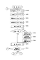
以上の各診断処理において、異常の判断が得られたときは、図11に示す診断結果フラグテーブルにおける所定の領域に”1”をセットしておく。そして、ステップS432では同診断結果フラグテーブルを参照し、異常検出があったか否かを判断し、異常があった場合はステップS434にて異常通知の処理を実施する。 When an abnormality determination is obtained in each of the above diagnostic processes, “1” is set in a predetermined area in the diagnostic result flag table shown in FIG. In step S432, the diagnosis result flag table is referenced to determine whether or not an abnormality has been detected. If there is an abnormality, an abnormality notification process is performed in step S434.
図12は、CPU11が実施する異常通知の処理のフローチャートであり、図13は異常通知の方法を選択する液晶表示パネル15b上の表示を示す図である。
通知の方法として選択できるのは、液晶表示パネル15bでの表示に加え、メールでの送信と、サーバの所定領域にあるログファイルへの追記である。図示しない操作用スイッチ15aにより、これらのいずれかを選択しておく。
異常通知のステップS450では、メール出力が選択されているか否かを判断し、選択されていればステップS452にて診断結果をメールとして送信する。
また、ステップS454では、ログ出力が選択されているか否かを判断し、選択されていればステップS456にて診断結果をメールとして送信する。
液晶表示パネル15bでの表示は常に行うものとしており、ステップS458にてメッセージタイプを読み込む。
本自己診断処理では、液晶表示パネル15bで表示するメッセージのタイプを選択することができるようにしており、具体的には図14に示す選択画面にて「標準バージョン」、「甘えんぼバージョン」、「関西弁バージョン」、「ENGLISH(英語)」のタイプから選択できる。図15は、タイプ毎のメッセージを記憶しているテーブル内容を示す図であり、一つの表示内容に対して各タイプごとに複数のメッセージを記憶している。メッセージはCODEで管理されているので、それぞれのシチュエーションに応じてメッセージの内容が決定されると、同内容に対応したCODEが決定されるため、あとは選択されているタイプを読み込んで同CODE内容で同テーブルを参照する。ステップS458は予め設定しておいたタイプの種別を読み込む処理であり、ステップS460は診断結果に対応するCODEの内容と上記タイプの種別で上記テーブルから実際に表示するメッセージを読み込む処理である。その後、ステップS462にて同メッセージを液晶表示パネル15bに表示し、異常通知処理を終了するとともに自己診断処理も終了する。
むろん、ステップS432にて異常が検出されなかった場合は、異常通知を実施することなく、自己診断処理を終了する。
(3)自動発注機能について
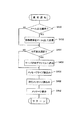
図16は、上述した自己診断処理の中で診断した補修品の診断結果に基づいて自動発注するためのフローチャートである。
CPU11は、所定のインターバルを置いて本補修品発注処理を実行する。インターバルは厳格である必要はなく、電源オンとなる毎であってもよいし、数回の電源オン毎であってもよいし、一定の時間、たとえば24時間を経過した毎であってもよい。ステップS470では自己診断結果を取得する。自己診断結果は、上述した自己診断処理のステップS431において記録した補修品テーブルの記録内容を取得する。そして、ステップS472では充電電池の良否の判定を行い、ステップS474ではサイドブラシとメインブラシの累積使用時間から補修の必要性の判定を行い、ステップS476ではサイドブラシとメインブラシを使用している間の累積走行時間から補修の必要性の判定を行い、ステップS478では駆動輪ユニットが正常に動作しているか否かの診断結果に基づいて良否の判定を行う。
FIG. 12 is a flowchart of the abnormality notification process performed by the
As a notification method, in addition to display on the liquid
In step S450 of the abnormality notification, it is determined whether or not mail output is selected. If it is selected, the diagnosis result is transmitted as mail in step S452.
In step S454, it is determined whether log output is selected. If it is selected, the diagnosis result is transmitted as an email in step S456.
The display on the liquid
In this self-diagnosis process, the type of message to be displayed on the liquid
Of course, if no abnormality is detected in step S432, the self-diagnosis process is terminated without performing abnormality notification.
(3) Automatic Order Function FIG. 16 is a flowchart for automatically placing an order based on the diagnosis result of the repaired product diagnosed in the self-diagnosis process described above.
The
本実施形態においては、ステップS431と、ステップS472〜S478の二段階で判定を行っているが、二段階とすることで信頼性の向上に貢献できる。また、二段階とすることで一段階目を基準値と比較し、二段階目では学習結果を反映させるということも可能である。むろん、いずれか一方だけの一段階の処理とすることも可能である。 In the present embodiment, the determination is performed in two steps, step S431 and steps S472 to S478. However, the two steps can contribute to improvement of reliability. It is also possible to compare the first stage with the reference value by using two stages and reflect the learning result in the second stage. Of course, it is also possible to set it as a one-step process only for either one.
ステップS480では、ステップS472〜S478の判定結果に基づいて補修の必要性の有無を判断する。何も補修の必要性がなければ、本補修品発注処理を終了する。しかし、補修の必要性がある場合には、ステップS482にてユーザーに対する発注の可否を問合せるメッセージを表示する。 In step S480, the necessity of repair is determined based on the determination results in steps S472 to S478. If there is no need for repair, the repair product ordering process is terminated. However, if there is a need for repair, a message asking whether the user can place an order is displayed in step S482.
図17はこの発注の可否を問合せるための液晶表示パネル15bでの表示例を示している。ここでは補修品のそれぞれを表示し、発注してもよいか否かを操作用スイッチ15aで操作できるようにしている。補修品である充電電池、ブラシ、駆動輪ユニットのそれぞれの前にはチェックボックスを設けてあり、必要な補修品に自動的にチェックが入るようにしている。ここで、ユーザは自動的にチェックの入ったもの以外の補修品にチェックを入れられるようにしてある。ユーザはまとめて発注することで送料を節約することを望むこともあるからである。また、チェックボックスの代わりに数量を指定できるようにしてもよい。
FIG. 17 shows a display example on the liquid
ユーザは必ずしも補修品を発注することを望むとは限らないので、ステップS486にてユーザの選択結果を判断し、発注してもよい場合にのみ、ステップS488にて無線LANを使用して自動発注する。具体的には、無線LANとインターネットを介して予め設けられているWEBサイトに入り、オーダーのためのデータを送信する。同WEBサイトでは各自走式掃除機について個別にオーナーを登録できるようにしてあり、各自走式掃除機のシリアル番号やマックアドレスに基づいて個体を識別し、発注された補修品を指定された住所に発送する処理を行うことになる。 Since the user does not necessarily want to order a repair product, the user's selection result is determined in step S486, and automatic ordering is performed using the wireless LAN in step S488 only when the order may be ordered. To do. Specifically, it enters a WEB site provided in advance via a wireless LAN and the Internet, and transmits data for ordering. The WEB site allows each self-propelled vacuum cleaner to be registered individually, identifies the individual based on the serial number and mac address of each self-propelled vacuum cleaner, and designates the repaired product ordered. Will be processed.
自動発注しても課金を回収できるのか不確定であると発送はできないので、ステップS490ではプリペイド型電子マネーで決済を行う。プリペイド型電子マネーは予めユーザーが所定の機関に対して料金を支払っておき、その証明に基づいて同機関を介して支払うことをシステムである。 If it is uncertain whether or not the charge can be collected even with automatic ordering, it cannot be shipped, and in step S490, settlement is made with prepaid electronic money. Prepaid electronic money is a system in which a user pays a fee in advance to a predetermined institution and pays through the institution based on the proof.
図18はプリペイド型電子マネーを利用する場合の液晶表示パネル15bにおける登録表示画面を示している。ユーザーは上記機関に料金を支払ったときに同機関から10桁程度の証明コードを付与されており、予め本自走式掃除機にこの証明コードを登録しておく。この証明コードを本自走式掃除機に登録しておくことにより、ステップS490では同証明コードを暗号化して補修品の業者に送信する。補修品の業者はこの証明コードが正当なものであってその時点での残高が課金額よりも多いか上記機関に問い合わせる。この結果、今回の課金よりも残高が大きいときには同機関が支払いをしてくれることが保障され、業者は安心して発送を行える。
FIG. 18 shows a registration display screen on the liquid
なお、上述した実施形態では、本自走式掃除機が直に無線LANを介して発注を行うようにしたが、発注はユーザーが普段使用している通常のコンピュータで行いたいという場合もあり、その場合は上記無線LANから同コンピュータに対して必要な情報を送信し、同コンピュータから同情報を利用して発注し直すというようにしてもよい。
むろん、プリペイド型電子マネーのシステムは各種のものがあるので、上記具体例以外のものであっても採用可能である。
In the above-described embodiment, the self-propelled cleaner directly places an order via a wireless LAN. However, there is a case where the user wants to place an order with a normal computer that the user normally uses. In that case, necessary information may be transmitted from the wireless LAN to the computer, and the order may be reordered from the computer using the information.
Of course, since there are various types of prepaid electronic money systems, it is possible to adopt other systems than the above specific examples.
このように、本自走式掃除機では、一連の自己診断の結果(ステップS400〜)や、普段の清掃走行時において累積しておいた使用時間と走行距離(ステップS270)とに基づいて、補修品の発注の必要性を判断しており(ステップS431,S472〜S478)、発注の必要性があれば、ユーザーに問合せた上で(ステップS482,S484)、無線LANとプリペイド型電子マネーによって発注および決済(ステップS488,S490)を行うようにしたので、在庫をもって消耗品を管理することのできない家庭での使用においても有効な自動発注を実現できる。 Thus, in this self-propelled cleaner, based on the results of a series of self-diagnosis (from step S400) and the usage time and travel distance (step S270) accumulated during normal cleaning travel, The necessity of ordering repair products is determined (steps S431, S472 to S478). If there is a need for ordering, the user is inquired (steps S482 and S484), and the wireless LAN and prepaid electronic money are used. Since ordering and settlement (steps S488 and S490) are performed, automatic ordering that is effective even at home use where consumables cannot be managed with inventory can be realized.
自己診断処理と組み合わせて補修品の自動発注を行うことが可能な自走式掃除機を提供することが可能となる。 It becomes possible to provide a self-propelled cleaner that can automatically order repair products in combination with self-diagnosis processing.
10…制御ユニット
20…人体感知ユニット
30…障害物監視ユニット
40…走行系ユニット
50…クリーナ系ユニット
60…カメラ系ユニット
70…無線LANユニット
DESCRIPTION OF
Claims (9)
無線LANにより外部と情報の送受信が可能な無線LAN通信手段と、
上記充電電池の良否の判断と、上記ブラシの使用時間と使用中の走行距離との累積に基づく同ブラシの良否の判断とを含むセルフチェックを行う自己診断手段と、
自己診断機能の結果に基づいて、上記充電電池の消耗の有無と、上記ブラシの累積使用時間と累積走行距離に基づく消耗の有無と、上記駆動輪の異常の有無と、必要な補修品を判断し、使用者に発注の可否を問合せてから上記無線LAN通信手段によって発注させる補修品発注制御手段とを具備することを特徴とする自走式掃除機。 A main body with a rechargeable battery and equipped with a cleaning mechanism that cleans using a brush, and a drive that is arranged on the left and right sides of the main body and can be controlled individually and can be changed into a unit that realizes steering and driving A self-propelled vacuum cleaner comprising a drive mechanism having a wheel,
A wireless LAN communication means capable of transmitting / receiving information to / from the outside via a wireless LAN;
Self-diagnostic means for performing a self-check including determination of pass / fail of the rechargeable battery and determination of pass / fail of the brush based on accumulation of usage time of the brush and travel distance during use;
Based on the result of the self-diagnosis function, the presence / absence of consumption of the rechargeable battery, the presence / absence of consumption based on the cumulative usage time and cumulative travel distance of the brush, the presence / absence of abnormality of the driving wheel, and necessary repairs are determined. A self-propelled cleaner, comprising: a repair product ordering control means for making an order by the wireless LAN communication means after inquiring the user whether or not ordering is possible.
無線LANにより外部と情報の送受信が可能な無線LAN通信手段と、
セルフチェックを行う自己診断手段と、
自己診断機能の結果に基づいて必要な補修品を判断し、上記無線LAN通信手段によって発注させる補修品発注制御手段とを具備することを特徴とする自走式掃除機。 A self-propelled cleaner comprising a main body provided with a cleaning mechanism and a drive mechanism capable of steering and driving,
A wireless LAN communication means capable of transmitting / receiving information to / from the outside via a wireless LAN;
Self-diagnosis means for self-checking;
A self-propelled cleaner, comprising: a repair product ordering control unit that determines a necessary repair product based on a result of the self-diagnosis function and places an order using the wireless LAN communication unit.
Priority Applications (2)
| Application Number | Priority Date | Filing Date | Title |
|---|---|---|---|
| JP2004120606A JP2005296511A (en) | 2004-04-15 | 2004-04-15 | Self-propelled vacuum cleaner |
| US11/105,107 US20050251457A1 (en) | 2004-04-15 | 2005-04-13 | Self-propelled cleaner |
Applications Claiming Priority (1)
| Application Number | Priority Date | Filing Date | Title |
|---|---|---|---|
| JP2004120606A JP2005296511A (en) | 2004-04-15 | 2004-04-15 | Self-propelled vacuum cleaner |
Publications (1)
| Publication Number | Publication Date |
|---|---|
| JP2005296511A true JP2005296511A (en) | 2005-10-27 |
Family
ID=35240564
Family Applications (1)
| Application Number | Title | Priority Date | Filing Date |
|---|---|---|---|
| JP2004120606A Withdrawn JP2005296511A (en) | 2004-04-15 | 2004-04-15 | Self-propelled vacuum cleaner |
Country Status (2)
| Country | Link |
|---|---|
| US (1) | US20050251457A1 (en) |
| JP (1) | JP2005296511A (en) |
Cited By (25)
| Publication number | Priority date | Publication date | Assignee | Title |
|---|---|---|---|---|
| JP2011161242A (en) * | 2005-12-02 | 2011-08-25 | Irobot Corp | Autonomous cleaning robot |
| US8239992B2 (en) | 2007-05-09 | 2012-08-14 | Irobot Corporation | Compact autonomous coverage robot |
| US8253368B2 (en) | 2004-01-28 | 2012-08-28 | Irobot Corporation | Debris sensor for cleaning apparatus |
| US8368339B2 (en) | 2001-01-24 | 2013-02-05 | Irobot Corporation | Robot confinement |
| US8374721B2 (en) | 2005-12-02 | 2013-02-12 | Irobot Corporation | Robot system |
| US8386081B2 (en) | 2002-09-13 | 2013-02-26 | Irobot Corporation | Navigational control system for a robotic device |
| US8382906B2 (en) | 2005-02-18 | 2013-02-26 | Irobot Corporation | Autonomous surface cleaning robot for wet cleaning |
| US8390251B2 (en) | 2004-01-21 | 2013-03-05 | Irobot Corporation | Autonomous robot auto-docking and energy management systems and methods |
| US8387193B2 (en) | 2005-02-18 | 2013-03-05 | Irobot Corporation | Autonomous surface cleaning robot for wet and dry cleaning |
| US8396592B2 (en) | 2001-06-12 | 2013-03-12 | Irobot Corporation | Method and system for multi-mode coverage for an autonomous robot |
| US8412377B2 (en) | 2000-01-24 | 2013-04-02 | Irobot Corporation | Obstacle following sensor scheme for a mobile robot |
| US8417383B2 (en) | 2006-05-31 | 2013-04-09 | Irobot Corporation | Detecting robot stasis |
| US8418303B2 (en) | 2006-05-19 | 2013-04-16 | Irobot Corporation | Cleaning robot roller processing |
| US8428778B2 (en) | 2002-09-13 | 2013-04-23 | Irobot Corporation | Navigational control system for a robotic device |
| US8463438B2 (en) | 2001-06-12 | 2013-06-11 | Irobot Corporation | Method and system for multi-mode coverage for an autonomous robot |
| US8474090B2 (en) | 2002-01-03 | 2013-07-02 | Irobot Corporation | Autonomous floor-cleaning robot |
| US8584305B2 (en) | 2005-12-02 | 2013-11-19 | Irobot Corporation | Modular robot |
| US8600553B2 (en) | 2005-12-02 | 2013-12-03 | Irobot Corporation | Coverage robot mobility |
| CN103584793A (en) * | 2012-08-17 | 2014-02-19 | 乐金电子(天津)电器有限公司 | Robot vacuum cleaner and self-diagnosing method thereof |
| US8788092B2 (en) | 2000-01-24 | 2014-07-22 | Irobot Corporation | Obstacle following sensor scheme for a mobile robot |
| US8793020B2 (en) | 2002-09-13 | 2014-07-29 | Irobot Corporation | Navigational control system for a robotic device |
| US8874264B1 (en) | 2004-07-07 | 2014-10-28 | Irobot Corporation | Celestial navigation system for an autonomous robot |
| US9008835B2 (en) | 2004-06-24 | 2015-04-14 | Irobot Corporation | Remote control scheduler and method for autonomous robotic device |
| US10314449B2 (en) | 2010-02-16 | 2019-06-11 | Irobot Corporation | Vacuum brush |
| JP2022019363A (en) * | 2020-07-17 | 2022-01-27 | 日立グローバルライフソリューションズ株式会社 | Vacuum cleaner management device, vacuum cleaner, and program |
Families Citing this family (37)
| Publication number | Priority date | Publication date | Assignee | Title |
|---|---|---|---|---|
| CN107422723B (en) | 2010-12-30 | 2021-08-24 | 美国iRobot公司 | Overlay robot navigation |
| DE102012206624A1 (en) * | 2012-04-23 | 2013-10-24 | Robert Bosch Gmbh | System with a vacuum cleaner and a hand vacuum cleaner |
| KR102142162B1 (en) | 2012-08-27 | 2020-09-14 | 에이비 엘렉트로룩스 | Robot positioning system |
| CN105101855A (en) | 2013-04-15 | 2015-11-25 | 伊莱克斯公司 | Robotic vacuum cleaner with protruding sidebrush |
| EP2986192B1 (en) | 2013-04-15 | 2021-03-31 | Aktiebolaget Electrolux | Robotic vacuum cleaner |
| KR102099495B1 (en) | 2013-12-19 | 2020-04-09 | 에이비 엘렉트로룩스 | Sensing climb of obstacle of a robotic cleaning device |
| US10209080B2 (en) | 2013-12-19 | 2019-02-19 | Aktiebolaget Electrolux | Robotic cleaning device |
| JP6638988B2 (en) | 2013-12-19 | 2020-02-05 | アクチエボラゲット エレクトロルックス | Robot vacuum cleaner with side brush and moving in spiral pattern |
| EP3084538B1 (en) | 2013-12-19 | 2017-11-01 | Aktiebolaget Electrolux | Robotic cleaning device with perimeter recording function |
| US9946263B2 (en) | 2013-12-19 | 2018-04-17 | Aktiebolaget Electrolux | Prioritizing cleaning areas |
| JP6687286B2 (en) | 2013-12-19 | 2020-04-22 | アクチエボラゲット エレクトロルックス | Robot cleaner and landmark recognition method |
| ES2675786T3 (en) | 2013-12-19 | 2018-07-12 | Aktiebolaget Electrolux | Adaptive speed control of rotary side brush |
| KR102116595B1 (en) | 2013-12-20 | 2020-06-05 | 에이비 엘렉트로룩스 | Dust container |
| JP6513709B2 (en) | 2014-07-10 | 2019-05-15 | アクチエボラゲット エレクトロルックス | Method of detecting measurement error in robot type cleaning device, robot type cleaning device, computer program and computer program product |
| CN104298235A (en) * | 2014-08-25 | 2015-01-21 | 洛阳理工学院 | Mobile robot system based on wireless video transmission and PID compound control |
| JP6826804B2 (en) | 2014-08-29 | 2021-02-10 | 東芝ライフスタイル株式会社 | Autonomous vehicle |
| JP6443897B2 (en) | 2014-09-08 | 2018-12-26 | アクチエボラゲット エレクトロルックス | Robot vacuum cleaner |
| US10729297B2 (en) | 2014-09-08 | 2020-08-04 | Aktiebolaget Electrolux | Robotic vacuum cleaner |
| WO2016091291A1 (en) | 2014-12-10 | 2016-06-16 | Aktiebolaget Electrolux | Using laser sensor for floor type detection |
| CN114668335A (en) | 2014-12-12 | 2022-06-28 | 伊莱克斯公司 | Side brush and robot dust catcher |
| KR102326401B1 (en) | 2014-12-16 | 2021-11-16 | 에이비 엘렉트로룩스 | Cleaning method for a robotic cleaning device |
| US10534367B2 (en) | 2014-12-16 | 2020-01-14 | Aktiebolaget Electrolux | Experience-based roadmap for a robotic cleaning device |
| JP6623522B2 (en) * | 2015-01-26 | 2019-12-25 | セイコーエプソン株式会社 | Robots, robot systems and servers |
| JP6743828B2 (en) | 2015-04-17 | 2020-08-19 | アクチエボラゲット エレクトロルックス | Robot vacuum and method for controlling the robot vacuum |
| CA2983944C (en) | 2015-04-24 | 2023-10-03 | Avidbots Corp. | Apparatus and methods for semi-autonomous cleaning of surfaces |
| US9746854B2 (en) | 2015-04-24 | 2017-08-29 | Autonomous Solutions, Inc. | System and method for controlling a vehicle |
| US10874274B2 (en) | 2015-09-03 | 2020-12-29 | Aktiebolaget Electrolux | System of robotic cleaning devices |
| WO2017157421A1 (en) | 2016-03-15 | 2017-09-21 | Aktiebolaget Electrolux | Robotic cleaning device and a method at the robotic cleaning device of performing cliff detection |
| CN109068908B (en) | 2016-05-11 | 2021-05-11 | 伊莱克斯公司 | Robot cleaning device |
| CN107505938A (en) * | 2016-06-14 | 2017-12-22 | 苏州宝时得电动工具有限公司 | Automatic running device and its sensor detecting method |
| US20180344116A1 (en) | 2017-06-02 | 2018-12-06 | Irobot Corporation | Scheduling and control system for autonomous robots |
| JP7243967B2 (en) | 2017-06-02 | 2023-03-22 | アクチエボラゲット エレクトロルックス | Method for Detecting Level Differences on a Surface in Front of a Robotic Cleaning Device |
| JP6854719B2 (en) * | 2017-07-11 | 2021-04-07 | パナソニック株式会社 | Equipment, robots, methods and programs |
| KR20200058400A (en) | 2017-09-26 | 2020-05-27 | 에이비 엘렉트로룩스 | Control the movement of the robot cleaning device |
| CN109744945B (en) * | 2017-11-08 | 2020-12-04 | 杭州萤石网络有限公司 | Method, device and system for determining regional attributes and electronic equipment |
| DE102018111211A1 (en) * | 2018-05-09 | 2019-11-14 | Miele & Cie. Kg | household appliance |
| CN114451832A (en) * | 2021-12-29 | 2022-05-10 | 深圳华芯信息技术股份有限公司 | Method, system, device and medium for managing consumables of automatic cleaning device |
-
2004
- 2004-04-15 JP JP2004120606A patent/JP2005296511A/en not_active Withdrawn
-
2005
- 2005-04-13 US US11/105,107 patent/US20050251457A1/en not_active Abandoned
Cited By (66)
| Publication number | Priority date | Publication date | Assignee | Title |
|---|---|---|---|---|
| US8788092B2 (en) | 2000-01-24 | 2014-07-22 | Irobot Corporation | Obstacle following sensor scheme for a mobile robot |
| US8478442B2 (en) | 2000-01-24 | 2013-07-02 | Irobot Corporation | Obstacle following sensor scheme for a mobile robot |
| US8761935B2 (en) | 2000-01-24 | 2014-06-24 | Irobot Corporation | Obstacle following sensor scheme for a mobile robot |
| US8565920B2 (en) | 2000-01-24 | 2013-10-22 | Irobot Corporation | Obstacle following sensor scheme for a mobile robot |
| US8412377B2 (en) | 2000-01-24 | 2013-04-02 | Irobot Corporation | Obstacle following sensor scheme for a mobile robot |
| US9622635B2 (en) | 2001-01-24 | 2017-04-18 | Irobot Corporation | Autonomous floor-cleaning robot |
| US8368339B2 (en) | 2001-01-24 | 2013-02-05 | Irobot Corporation | Robot confinement |
| US9038233B2 (en) | 2001-01-24 | 2015-05-26 | Irobot Corporation | Autonomous floor-cleaning robot |
| US8686679B2 (en) | 2001-01-24 | 2014-04-01 | Irobot Corporation | Robot confinement |
| US8396592B2 (en) | 2001-06-12 | 2013-03-12 | Irobot Corporation | Method and system for multi-mode coverage for an autonomous robot |
| US8838274B2 (en) | 2001-06-12 | 2014-09-16 | Irobot Corporation | Method and system for multi-mode coverage for an autonomous robot |
| US8463438B2 (en) | 2001-06-12 | 2013-06-11 | Irobot Corporation | Method and system for multi-mode coverage for an autonomous robot |
| US8671507B2 (en) | 2002-01-03 | 2014-03-18 | Irobot Corporation | Autonomous floor-cleaning robot |
| US8656550B2 (en) | 2002-01-03 | 2014-02-25 | Irobot Corporation | Autonomous floor-cleaning robot |
| US8516651B2 (en) | 2002-01-03 | 2013-08-27 | Irobot Corporation | Autonomous floor-cleaning robot |
| US8474090B2 (en) | 2002-01-03 | 2013-07-02 | Irobot Corporation | Autonomous floor-cleaning robot |
| US9128486B2 (en) | 2002-01-24 | 2015-09-08 | Irobot Corporation | Navigational control system for a robotic device |
| US8386081B2 (en) | 2002-09-13 | 2013-02-26 | Irobot Corporation | Navigational control system for a robotic device |
| US8428778B2 (en) | 2002-09-13 | 2013-04-23 | Irobot Corporation | Navigational control system for a robotic device |
| US8793020B2 (en) | 2002-09-13 | 2014-07-29 | Irobot Corporation | Navigational control system for a robotic device |
| US8854001B2 (en) | 2004-01-21 | 2014-10-07 | Irobot Corporation | Autonomous robot auto-docking and energy management systems and methods |
| US8461803B2 (en) | 2004-01-21 | 2013-06-11 | Irobot Corporation | Autonomous robot auto-docking and energy management systems and methods |
| US8749196B2 (en) | 2004-01-21 | 2014-06-10 | Irobot Corporation | Autonomous robot auto-docking and energy management systems and methods |
| US8390251B2 (en) | 2004-01-21 | 2013-03-05 | Irobot Corporation | Autonomous robot auto-docking and energy management systems and methods |
| US8456125B2 (en) | 2004-01-28 | 2013-06-04 | Irobot Corporation | Debris sensor for cleaning apparatus |
| US8378613B2 (en) | 2004-01-28 | 2013-02-19 | Irobot Corporation | Debris sensor for cleaning apparatus |
| US8253368B2 (en) | 2004-01-28 | 2012-08-28 | Irobot Corporation | Debris sensor for cleaning apparatus |
| US8598829B2 (en) | 2004-01-28 | 2013-12-03 | Irobot Corporation | Debris sensor for cleaning apparatus |
| US9008835B2 (en) | 2004-06-24 | 2015-04-14 | Irobot Corporation | Remote control scheduler and method for autonomous robotic device |
| US8874264B1 (en) | 2004-07-07 | 2014-10-28 | Irobot Corporation | Celestial navigation system for an autonomous robot |
| US8382906B2 (en) | 2005-02-18 | 2013-02-26 | Irobot Corporation | Autonomous surface cleaning robot for wet cleaning |
| US8855813B2 (en) | 2005-02-18 | 2014-10-07 | Irobot Corporation | Autonomous surface cleaning robot for wet and dry cleaning |
| US8392021B2 (en) | 2005-02-18 | 2013-03-05 | Irobot Corporation | Autonomous surface cleaning robot for wet cleaning |
| US8387193B2 (en) | 2005-02-18 | 2013-03-05 | Irobot Corporation | Autonomous surface cleaning robot for wet and dry cleaning |
| US8661605B2 (en) | 2005-12-02 | 2014-03-04 | Irobot Corporation | Coverage robot mobility |
| JP2016105823A (en) * | 2005-12-02 | 2016-06-16 | アイロボット コーポレイション | Coverage robot |
| US11737632B2 (en) | 2005-12-02 | 2023-08-29 | Irobot Corporation | Modular robot |
| US10524629B2 (en) | 2005-12-02 | 2020-01-07 | Irobot Corporation | Modular Robot |
| US8606401B2 (en) | 2005-12-02 | 2013-12-10 | Irobot Corporation | Autonomous coverage robot navigation system |
| US8600553B2 (en) | 2005-12-02 | 2013-12-03 | Irobot Corporation | Coverage robot mobility |
| US8584305B2 (en) | 2005-12-02 | 2013-11-19 | Irobot Corporation | Modular robot |
| US8380350B2 (en) | 2005-12-02 | 2013-02-19 | Irobot Corporation | Autonomous coverage robot navigation system |
| JP2011161242A (en) * | 2005-12-02 | 2011-08-25 | Irobot Corp | Autonomous cleaning robot |
| US9149170B2 (en) | 2005-12-02 | 2015-10-06 | Irobot Corporation | Navigating autonomous coverage robots |
| US10070763B2 (en) | 2005-12-02 | 2018-09-11 | Irobot Corporation | Modular robot |
| US9144360B2 (en) | 2005-12-02 | 2015-09-29 | Irobot Corporation | Autonomous coverage robot navigation system |
| US8954192B2 (en) | 2005-12-02 | 2015-02-10 | Irobot Corporation | Navigating autonomous coverage robots |
| US8374721B2 (en) | 2005-12-02 | 2013-02-12 | Irobot Corporation | Robot system |
| US8528157B2 (en) | 2006-05-19 | 2013-09-10 | Irobot Corporation | Coverage robots and associated cleaning bins |
| US8418303B2 (en) | 2006-05-19 | 2013-04-16 | Irobot Corporation | Cleaning robot roller processing |
| US9955841B2 (en) | 2006-05-19 | 2018-05-01 | Irobot Corporation | Removing debris from cleaning robots |
| US8572799B2 (en) | 2006-05-19 | 2013-11-05 | Irobot Corporation | Removing debris from cleaning robots |
| US8417383B2 (en) | 2006-05-31 | 2013-04-09 | Irobot Corporation | Detecting robot stasis |
| US8839477B2 (en) | 2007-05-09 | 2014-09-23 | Irobot Corporation | Compact autonomous coverage robot |
| US8239992B2 (en) | 2007-05-09 | 2012-08-14 | Irobot Corporation | Compact autonomous coverage robot |
| US9480381B2 (en) | 2007-05-09 | 2016-11-01 | Irobot Corporation | Compact autonomous coverage robot |
| US10070764B2 (en) | 2007-05-09 | 2018-09-11 | Irobot Corporation | Compact autonomous coverage robot |
| US8438695B2 (en) | 2007-05-09 | 2013-05-14 | Irobot Corporation | Autonomous coverage robot sensing |
| US11072250B2 (en) | 2007-05-09 | 2021-07-27 | Irobot Corporation | Autonomous coverage robot sensing |
| US11498438B2 (en) | 2007-05-09 | 2022-11-15 | Irobot Corporation | Autonomous coverage robot |
| US8726454B2 (en) | 2007-05-09 | 2014-05-20 | Irobot Corporation | Autonomous coverage robot |
| US10314449B2 (en) | 2010-02-16 | 2019-06-11 | Irobot Corporation | Vacuum brush |
| US11058271B2 (en) | 2010-02-16 | 2021-07-13 | Irobot Corporation | Vacuum brush |
| CN103584793A (en) * | 2012-08-17 | 2014-02-19 | 乐金电子(天津)电器有限公司 | Robot vacuum cleaner and self-diagnosing method thereof |
| JP2022019363A (en) * | 2020-07-17 | 2022-01-27 | 日立グローバルライフソリューションズ株式会社 | Vacuum cleaner management device, vacuum cleaner, and program |
| JP7296347B2 (en) | 2020-07-17 | 2023-06-22 | 日立グローバルライフソリューションズ株式会社 | Vacuum cleaner management device, vacuum cleaner and program |
Also Published As
| Publication number | Publication date |
|---|---|
| US20050251457A1 (en) | 2005-11-10 |
Similar Documents
| Publication | Publication Date | Title |
|---|---|---|
| JP2005296511A (en) | Self-propelled vacuum cleaner | |
| JP3841220B2 (en) | Autonomous traveling robot cleaner | |
| KR101840150B1 (en) | Autonomous traveling body | |
| JP3478476B2 (en) | Cleaning robot | |
| US20060273749A1 (en) | System and method for automatically returning self-moving robot to charger | |
| US20060080802A1 (en) | Self-propelled cleaner charging-type travel system and charging-type travel system | |
| US20140115797A1 (en) | Self-driven floor cleaning device | |
| JP2005304540A (en) | Self-running type vacuum cleaner equipped with monitoring camera | |
| JP2000353014A (en) | Cleaning robot | |
| US20060132318A1 (en) | Self-propelled cleaner and self-propelled traveling apparatus | |
| CN109938642B (en) | Electric vacuum cleaner | |
| JP2019082807A (en) | Augmented reality display system, terminal device, augmented reality display method and autonomously travelling cleaner | |
| JP2000342498A (en) | Cleaning robot | |
| US20050234595A1 (en) | Self-propelled cleaner and method of controlling the same | |
| US20210173403A1 (en) | Autonomous traveling system, autonomous traveling method, and autonomous traveling program stored on computer-readable storage medium | |
| JP2005211367A (en) | Autonomous traveling robot cleaner | |
| JP2021141753A (en) | Charging mobile device and charging system | |
| JP2005270413A (en) | Self-propelled vacuum cleaner | |
| CN103584797A (en) | Robot vacuum cleaner and self-diagnosing method thereof | |
| US20060123582A1 (en) | Self-propelled cleaner | |
| JP2006061439A (en) | Self-propelled vacuum cleaner | |
| US20070118288A1 (en) | Travel device | |
| JP2006043175A (en) | Self-travelling vacuum cleaner | |
| JP3721939B2 (en) | Mobile work robot | |
| JP2005275898A (en) | Self-propelled cleaner |
Legal Events
| Date | Code | Title | Description |
|---|---|---|---|
| RD04 | Notification of resignation of power of attorney |
Free format text: JAPANESE INTERMEDIATE CODE: A7424 Effective date: 20051221 |
|
| A761 | Written withdrawal of application |
Free format text: JAPANESE INTERMEDIATE CODE: A761 Effective date: 20060915 |