JP2005292320A - Image microscopic device - Google Patents
Image microscopic device Download PDFInfo
- Publication number
- JP2005292320A JP2005292320A JP2004104957A JP2004104957A JP2005292320A JP 2005292320 A JP2005292320 A JP 2005292320A JP 2004104957 A JP2004104957 A JP 2004104957A JP 2004104957 A JP2004104957 A JP 2004104957A JP 2005292320 A JP2005292320 A JP 2005292320A
- Authority
- JP
- Japan
- Prior art keywords
- image display
- display device
- imaging device
- image
- arm
- Prior art date
- Legal status (The legal status is an assumption and is not a legal conclusion. Google has not performed a legal analysis and makes no representation as to the accuracy of the status listed.)
- Pending
Links
Images
Classifications
-
- G—PHYSICS
- G02—OPTICS
- G02B—OPTICAL ELEMENTS, SYSTEMS OR APPARATUS
- G02B21/00—Microscopes
- G02B21/0004—Microscopes specially adapted for specific applications
- G02B21/0012—Surgical microscopes
-
- A—HUMAN NECESSITIES
- A61—MEDICAL OR VETERINARY SCIENCE; HYGIENE
- A61B—DIAGNOSIS; SURGERY; IDENTIFICATION
- A61B90/00—Instruments, implements or accessories specially adapted for surgery or diagnosis and not covered by any of the groups A61B1/00 - A61B50/00, e.g. for luxation treatment or for protecting wound edges
- A61B90/20—Surgical microscopes characterised by non-optical aspects
- A61B90/25—Supports therefor
-
- A—HUMAN NECESSITIES
- A61—MEDICAL OR VETERINARY SCIENCE; HYGIENE
- A61B—DIAGNOSIS; SURGERY; IDENTIFICATION
- A61B90/00—Instruments, implements or accessories specially adapted for surgery or diagnosis and not covered by any of the groups A61B1/00 - A61B50/00, e.g. for luxation treatment or for protecting wound edges
- A61B90/36—Image-producing devices or illumination devices not otherwise provided for
-
- A—HUMAN NECESSITIES
- A61—MEDICAL OR VETERINARY SCIENCE; HYGIENE
- A61B—DIAGNOSIS; SURGERY; IDENTIFICATION
- A61B90/00—Instruments, implements or accessories specially adapted for surgery or diagnosis and not covered by any of the groups A61B1/00 - A61B50/00, e.g. for luxation treatment or for protecting wound edges
- A61B90/50—Supports for surgical instruments, e.g. articulated arms
-
- G—PHYSICS
- G02—OPTICS
- G02B—OPTICAL ELEMENTS, SYSTEMS OR APPARATUS
- G02B21/00—Microscopes
- G02B21/36—Microscopes arranged for photographic purposes or projection purposes or digital imaging or video purposes including associated control and data processing arrangements
- G02B21/362—Mechanical details, e.g. mountings for the camera or image sensor, housings
-
- G—PHYSICS
- G02—OPTICS
- G02B—OPTICAL ELEMENTS, SYSTEMS OR APPARATUS
- G02B21/00—Microscopes
- G02B21/36—Microscopes arranged for photographic purposes or projection purposes or digital imaging or video purposes including associated control and data processing arrangements
- G02B21/368—Microscopes arranged for photographic purposes or projection purposes or digital imaging or video purposes including associated control and data processing arrangements details of associated display arrangements, e.g. mounting of LCD monitor
-
- A—HUMAN NECESSITIES
- A61—MEDICAL OR VETERINARY SCIENCE; HYGIENE
- A61B—DIAGNOSIS; SURGERY; IDENTIFICATION
- A61B17/00—Surgical instruments, devices or methods, e.g. tourniquets
- A61B2017/00477—Coupling
-
- A—HUMAN NECESSITIES
- A61—MEDICAL OR VETERINARY SCIENCE; HYGIENE
- A61B—DIAGNOSIS; SURGERY; IDENTIFICATION
- A61B90/00—Instruments, implements or accessories specially adapted for surgery or diagnosis and not covered by any of the groups A61B1/00 - A61B50/00, e.g. for luxation treatment or for protecting wound edges
- A61B90/36—Image-producing devices or illumination devices not otherwise provided for
- A61B90/37—Surgical systems with images on a monitor during operation
- A61B2090/372—Details of monitor hardware
-
- A—HUMAN NECESSITIES
- A61—MEDICAL OR VETERINARY SCIENCE; HYGIENE
- A61B—DIAGNOSIS; SURGERY; IDENTIFICATION
- A61B90/00—Instruments, implements or accessories specially adapted for surgery or diagnosis and not covered by any of the groups A61B1/00 - A61B50/00, e.g. for luxation treatment or for protecting wound edges
- A61B90/20—Surgical microscopes characterised by non-optical aspects
Landscapes
- Health & Medical Sciences (AREA)
- Surgery (AREA)
- Life Sciences & Earth Sciences (AREA)
- Physics & Mathematics (AREA)
- Engineering & Computer Science (AREA)
- General Health & Medical Sciences (AREA)
- General Physics & Mathematics (AREA)
- Medical Informatics (AREA)
- Nuclear Medicine, Radiotherapy & Molecular Imaging (AREA)
- Oral & Maxillofacial Surgery (AREA)
- Pathology (AREA)
- Analytical Chemistry (AREA)
- Chemical & Material Sciences (AREA)
- Biomedical Technology (AREA)
- Heart & Thoracic Surgery (AREA)
- Optics & Photonics (AREA)
- Molecular Biology (AREA)
- Animal Behavior & Ethology (AREA)
- Public Health (AREA)
- Veterinary Medicine (AREA)
- Multimedia (AREA)
- Microscoopes, Condenser (AREA)
- Apparatus For Radiation Diagnosis (AREA)
- Endoscopes (AREA)
Abstract
Description
本発明は、被検部を拡大観察しながら処置を行うための顕微鏡装置に関する。 The present invention relates to a microscope apparatus for performing treatment while observing a portion to be examined in an enlarged manner.
脳神経外科や耳鼻咽喉科などの手術においてはその手術の成績向上のため、精密な作業を行う必要があり、被検術部を拡大観察が可能な顕微鏡を用いた手術が一般的に行われている。これらの手術においては被検部に対してあらゆる方向から処置を施す必要があるため、顕微鏡は様々な位置及び角度に移動及び固定が可能なものでなければならない。従って、顕微鏡は複数の可動部を有した支持アームによって支持されている。この種の顕微鏡用支持アームの公知例として以下に挙げるような種類の特許文献がある。
一方、近年の電子技術の急速な進歩により、上述した手術用顕微鏡の分野においても電子画像化の流れは始まっており、従来の光学式顕微鏡に対してデジタル画像方式の手術用顕微鏡の試みが始まっている。このデジタル画像方式の手術用顕微鏡としては以下に挙げるような特許文献に示されるものがある。
上述した特許文献1〜4にある手術用顕微鏡はいずれも被検部を観察する顕微鏡本体が一体的に構成されている。このような顕微鏡本体は被検部からの光束を取り込む対物レンズと、術者が拡大された被検部の光学像を覗き込む接眼レンズを有し、これらが一体或いは一体的なハウジングに組み込まれた一体構成であるため、被検部を様々な条件で観察する場合にあっては当然に接眼レンズも対物レンズと同時に動いてしまう。従って、術者が、観察対象の部位を変更しようとする場合は、その都度、自分自身が移動しなければならなかった。さらに被検部を斜めから観察するために顕微鏡本体を大きく傾けた場合には辛い姿勢での観察をしいられてしまう。手術は当然、観察しながら処置を行うものであるので、辛い姿勢では容易に処置ができない場合さえ生じてしまい、これでは術者にとって疲れを招き易い。
In each of the surgical microscopes described in
一方、上述した特許文献5,6の手術用顕微鏡では上述した手術用顕微鏡の場合とは逆に、被検部からの光束を取り込む部分(撮像部)と、拡大された被検部の画像を表示する手段(画像表示装置)とが別体で構成されている。しかし、被検部を斜めから観察するために撮像装置を傾けても、画像表示装置の状態はそのままであるため、術者の体の向きはそのまま保たれ、被検部に処置を施そうとした場合、体の正面ではない方向に腕を伸ばし体の向きとは関係のない方向から処置を施すことになってしまう。従って、術者は腕の疲れや不自然な感覚を受ける姿勢で手術を行なわなければならない。
On the other hand, in the above-described surgical microscopes of
これらの事情は、撮像装置の傾斜や移動が大きくなればなる程、顕微鏡観察下で手術を行う上での支障となる。また、撮像装置を移動させる度に画像表示装置を最適な位置に移動させれば、このような問題は防げるが、その作業は非常に面倒なものであることは明らかである。 In these circumstances, the greater the inclination and movement of the imaging device, the more difficult it is to perform an operation under microscope observation. Further, if the image display device is moved to an optimal position each time the image pickup device is moved, such a problem can be prevented, but it is obvious that the operation is very troublesome.
本発明は上記課題に着目してなされたもので、その目的とするところは、手術における術者の疲労を排除するため、撮像装置と画像表示装置とを常に最適な形態で支持することができる画像顕微鏡装置を提供することである。 The present invention has been made paying attention to the above-mentioned problems, and the object of the present invention is to always support the imaging device and the image display device in an optimal form in order to eliminate the fatigue of the operator in the operation. An image microscope apparatus is provided.
本発明は、被検部を撮像する撮像装置と、上記撮像装置によって撮像した画像を表示する画像表示装置と、上記撮像装置及び上記画像表示装置同士を着脱自在となるよう接続する着脱式接続手段とを具備したことを特徴とする画像顕微鏡装置である。
通常、撮像装置と画像表示装置を接続した状態で手術を行い、術中に撮像装置を大きく傾ける(被検部を大きく傾斜した方向から観察する)必要が生じた場合、撮像装置と画像表示装置とを分離させることができる。従って、術者は辛い姿勢から解放され手術を続けることが可能となる。また、術者の好みによって装着或いは分離を選択して使用することも可能である。
The present invention relates to an imaging device that images a portion to be examined, an image display device that displays an image captured by the imaging device, and a detachable connection unit that connects the imaging device and the image display device so as to be detachable. And an image microscope apparatus.
Usually, when surgery is performed with the imaging device and the image display device connected, and it becomes necessary to tilt the imaging device greatly during the operation (observation from the direction in which the subject is greatly tilted), the imaging device and the image display device Can be separated. Therefore, the surgeon is released from the painful posture and can continue the operation. It is also possible to select and use wearing or separating according to the operator's preference.
本発明によれば、術者の好みによって撮像装置と画像表示装置とを、装着或いは分離を選択して使用することが可能である。さらに、通常、撮像装置と画像表示装置を接続した状態で手術を行い、術中に撮像装置を大きく傾ける(被検部を大きく傾斜した方向から観察する)必要が生じた場合、撮像装置と画像表示装置とを分離させることができる。従って、術者は常に楽な姿勢で手術を行うことが可能となる。 According to the present invention, it is possible to use the imaging device and the image display device by selecting mounting or separation depending on the preference of the surgeon. Further, usually, when an operation is performed with the imaging device connected to the image display device, and it becomes necessary to tilt the imaging device greatly during the operation (observation from the direction in which the test portion is greatly tilted), the imaging device and the image display are displayed. The device can be separated. Therefore, the surgeon can always perform an operation with a comfortable posture.
〔第1の実施形態〕
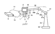
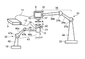
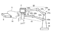
図1〜図2に基づいて本発明の第1の実施形態に係る画像顕微鏡装置を説明する。図1は撮像装置と画像表示装置が接続された使用状態の説明図であり、図2は撮像装置と画像表示装置が分離された使用状態の説明図である。
[First Embodiment]
An image microscope apparatus according to a first embodiment of the present invention will be described with reference to FIGS. FIG. 1 is an explanatory diagram of a usage state in which an imaging device and an image display device are connected, and FIG. 2 is an explanatory diagram of a usage state in which the imaging device and the image display device are separated.
(構成)
図1中、符号1で示すものは画像顕微鏡装置の撮像装置(撮像手段)であり、符号2で示すものは画像顕微鏡装置の画像表示装置(画像表示手段)である。撮像装置1と画像表示装置2は後述する着脱自在な接続手段によって着脱が自在である。
(Constitution)
In FIG. 1,
上記撮像装置1は本体(ハウジング)3を有しており、この本体3の中には生体の被検部4からの光束を取り込む対物レンズ5と、この対物レンズ5から出射した光束が入射する結像レンズ6と、この結像レンズ6の結像位置7に受光面を配置した撮像素子8が配設されている。上記撮像装置1には撮像素子8からの撮像信号を、カメラコントロールユニット(CCU)9に導く信号ケーブル10が接続されている。CCU9は上述した撮像装置1と画像表示装置2の位置から離れて極力邪魔にならない場所に設置される。
The
上記画像表示装置2は例えばLCD等に代表される画像表示装置である。この画像表示装置2には上記CCU9からの映像ケーブル11が接続されていて、この映像ケーブル11によって上記CCU9からの映像信号を上記画像表示装置2に導くようになっている。
The
上記画像表示装置2には上記撮像装置1を取り付けるための第1着脱部15が装置本体16の下面に設けられている。図2に示すように、この第1着脱部15は下方へ突出する直径Aの嵌合軸17が設けられ、この嵌合軸17を用いて上記撮像装置1を上記画像表示装置2に装着する。また、上記撮像装置1の本体3の上部には上記画像表示装置2を取り付けるための第2着脱部18が設けられている。この第2着脱部18は上記画像表示装置2の嵌合軸17を嵌め込める直径Aの嵌合穴19が形成され、この嵌合穴19に上記嵌合軸17を嵌め込み装着すると共に、後述する締付け手段によって所定の位置関係で固定する。上記締付け手段は上記嵌合穴19に直交する方向から該嵌合穴19に貫通して第2着脱部18に設けられたネジ孔21と、このネジ孔21に螺合する雄ネジ部を有するツマミ22とを含む。
The
図1に示すように、上記画像表示装置2は、第1保持架台31によって3次元的に移動自在でかつ任意の位置にて固定可能なように支持される。また、上記撮像装置1は図2に示すように、第2保持架台32によって3次元的に移動自在でかつ任意の位置にて固定可能に支持される。
As shown in FIG. 1, the
第1保持架台31はベース33と支柱34と支持アーム35とを備える。上記支持アーム35は第1アーム36aと第2アーム36bから構成されている。第1アーム36aと支柱34は第1球体軸受37aによって可動が可能に連結され、また、第1アーム36aと第2アーム36bは第2球体軸受37bによって可動が可能に連結されている。
The
上記撮像装置1は支持アーム35における第2アーム36bの先端に対し着脱自在に取り付けられるようになっている。第1球体軸受37a及び第2球体軸受37bはそれの先端にかかる重量によって生じるモーメントによって支持アーム35が自然に動かないフリクションを備えている。また、支持アーム35における可動部分に選択的に操作が可能なロック手段を付加して支持アーム35が移動しないように固定するようにしても良い。例えば、球体軸受37a,37bにスイッチによる入力により固定/解除が行われる電磁ブレーキ(図示しない)等を内蔵する。
The
また、図2に示す第2保持架台32も第1保持架台31の構成と略同様に構成されている。すなわち、第2保持架台32はベース41と支柱42と支持アーム43を備える。上記支持アーム43は第1アーム46aと第2アーム46bから構成される。第1アーム46aと支柱42は第1球体軸受47aによって可動が可能に連結され、また、第1アーム46aと第2アーム46bは第2球体軸受47bによって可動が可能に連結されている。上記撮像装置1は支持アーム43における第2アーム46bの先端に対し着脱自在に取り付けられるようになっている。第1球体軸受47a及び第2球体軸受47bはそれの先端にかかる重量によって生じるモーメントによって支持アーム43が自然に動かないフリクションを備えている。また、支持アーム43における可動部分に選択的に任意に操作が可能なロック手段を付加してその支持アーム43が移動しないように固定するようにしても良い。
Further, the
(作用)
次に、本実施形態の画像顕微鏡装置の使用例について説明する。図1は撮像装置1と画像表示装置2とが一体的に接続された使用状態である。この接続状態では上記画像表示装置2の嵌合軸17を上記撮像装置1の嵌合穴19に嵌着させるとともに、上記ツマミ22を締め込むことによって嵌合軸17を締結することで固定的になる。このとき、撮像装置1を画像表示装置2に装着したので、第1保持架台31の使用のみで済み、第2保持架台32を使用しないで済む。
(Function)
Next, a usage example of the image microscope apparatus of the present embodiment will be described. FIG. 1 shows a use state in which the
図1に示す如く、撮像装置(撮像部)1を被検部4に向けると、対物レンズ5にて取り込まれた被検部4からの光束は結像レンズ6により撮像素子8の受光面上に結像される。この画像は撮像素子8によって撮像され、ここで得られた被検部4の画像の撮像信号は信号ケーブル10を通じてCCU9に入力し、映像信号に変換される。この映像信号は映像ケーブル11を介して画像表示装置2に伝送され、そのモニタ画面に画像が映し出される。
As shown in FIG. 1, when the imaging device (imaging unit) 1 is directed to the
図1に示すように、撮像装置1と画像表示装置2とが一体的に接続された状態では、被検部4を観察する際、その観察部位を左右に移動させたり、或いは被検部4を異なる方向から観察しようとする場合、術者は第1保持架台31の支持アーム35の有する球体軸受37a,37bの可動域を利用して撮像装置1を水平移動させたり傾斜させたりする。このとき、画像表示装置2は撮像装置1に一体的に固定されているため、撮像装置1の移動に伴って追従移動する。従って、画像表示装置2を観察する術者は体を移動或いは傾斜させることになる。
As shown in FIG. 1, in the state where the
次に、上記撮像装置1と上記画像表示装置2とを分離して使用する場合について説明する。上記撮像装置1と上記画像表示装置2とを分離する場合は、上記ツマミ22を緩めて上記嵌合軸17を上記嵌合穴19から引き抜くことで成し得る。そして、図2に示すように、上記画像表示装置2から切り離されて単独になった撮像装置1を、第2保持架台32における支持アーム43の先端に対し取り付ける。
Next, a case where the
この使用形態の場合は、図2に示すように、術者は被検部4を観察する際、その撮像装置(撮像部)1を左右に移動させたり、或いは被検部4を異なる方向から観察しようとする場合には、第2保持架台32における支持アーム43の球体軸受47a,47bの可動域を利用して撮像装置1を水平移動させたり傾斜させたりする。この際、画像表示装置2は撮像装置1に対して分離されているため、画像表示装置2は撮像装置1の移動には関係なくその設置状態を保つ。従って、画像表示装置2を観察する術者は姿勢を変える必要がない。
In the case of this use form, as shown in FIG. 2, when observing the
(効果)
本実施形態によれば、撮像装置(撮像部)1の観察方向の変更に伴って画像表示装置2の位置状態を追従させる使用形態と、撮像装置(撮像部)1の観察方向の変更に拘わらず、画像表示装置2はそのままの位置状態を保つ使用形態の両方が可能である。従って、術前のセッティングによって使用状況または術者の好み等に応じた使用法の選択が可能となる。
(effect)
According to the present embodiment, the usage mode in which the position state of the
また、術者は画像表示装置2のみの配置を変えたい場合、第1保持架台31の支持アーム35を動かすことによって、撮像装置1とは独立してその配置を変えることができる。撮像装置1のみの配置を変えたい場合は、第2保持架台32の支持アーム35を動かすことによって、撮像装置1のみを独立してその配置を変えることができる。
Further, when the operator wants to change the arrangement of only the
ところで、本実施形態では撮像装置1と画像表示装置2との着脱に嵌合軸17を用いるものであったが、この着脱式接続手段としては、磁石のような磁性体を用いても良いし、或いは雄ネジと雌ネジによる固定法を使う等、種々の方式のものが考えられることはいうまでもない。さらに本実施形態では撮像装置1または画像表示装置2を移動可能に保持するために、フリクションを有した球面軸受を用いて説明を行ったが、平行四辺形リンクにスプリングや錘を組み合わせた所謂バランス式パンタグラフアームを用いても良い。この場合は、アームの先端にかかる重量が画像表示装置2のみである場合と、撮像装置1と画像表示装置2との両方の重量がかかる場合とを認識し、各々の状態に合わせて自動でバランスの調整が行われることが好ましい。
By the way, in this embodiment, the
〔第2の実施形態〕
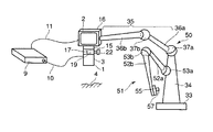
図3及び図4に基づいて本発明の第2の実施形態に係る画像顕微鏡装置を説明する。ただし、上述した第1の実施形態と同一の構成のものについては同一の符号を付し、その詳細な説明を省略する。図4は撮像装置と画像表示装置が接続された使用状態の説明図であり、図5は撮像装置と画像表示装置が分離された使用状態の説明図である。
[Second Embodiment]
An image microscope apparatus according to the second embodiment of the present invention will be described with reference to FIGS. However, the same components as those in the first embodiment described above are denoted by the same reference numerals, and detailed description thereof is omitted. FIG. 4 is an explanatory diagram of the usage state in which the imaging device and the image display device are connected, and FIG. 5 is an explanatory diagram of the usage state in which the imaging device and the image display device are separated.
(構成)
本実施形態での撮像装置1及び画像表示装置2は上述した第1の実施形態のものと略同様に構成されるが、本実施形態では一台の保持架台50で撮像装置1及び画像表示装置2の両方を支持できるようにしたものである。
(Constitution)
The
図3に示すように、本実施形態では一台の保持架台50を備え、この保持架台50は上述した第1の実施形態に示した第1保持架台31と同様にベース33と支柱34と支持アーム35とを備え、上記支持アーム35は第1アーム36aと第2アーム36bから構成されている。第1アーム36aと支柱34は第1球体軸受37aによって可動が可能に連結され、また、第1アーム36aと第2アーム36bは第2球体軸受37bによって可動が可能に連結されている。この支持アーム35における第2アーム36bの先端に対して画像表示装置2を脱自在に取り付けるようにしてある。
As shown in FIG. 3, in this embodiment, a
さらに、本実施形態の保持架台50ではその支柱34に上記画像表示装置用支持アーム35とは別のアーム51を設け、この別のアーム51に撮像装置1を支持可能なものとした。この撮像装置用支持アーム51は図1に示すように、第1のアーム52aと第2アーム52bから構成されており、第1アーム52aと支柱34は第1球体軸受53aによって可動が可能に連結され、また、第1アーム52aと第2アーム52bは第2球体軸受53bによって可動が可能に連結されている。第1球体軸受53a及び第2球体軸受53bにはスイッチによる入力により固定/解除が行われる電磁ブレーキ(図示しない)等が内蔵されている。
Further, in the holding
この撮像装置用支持アーム51における第2アーム52bの先端には上記撮像装置1を着脱自在に装着する第3着脱部55が設けられている。この第3着脱部55には、上述した第1着脱部15と同様に構成される。つまり、第3着脱部55には図4に示すように、下方へ突出する直径Aの嵌合用軸57が設けられている。
A third attachment /
(作用)
図3に示すように、上記撮像装置1と上記画像表示装置2を一体的に接続して使用する場合では、上述した実施形態の場合と同様、支持アーム35の先端に画像表示装置2を支持し、撮像装置1はその画像表示装置2に一体的に接続された状態にある。このとき、別のアーム51は図3に示すように折り畳まれ、収納状態にある。
(Function)
As shown in FIG. 3, when the
次に、上記撮像装置1と上記画像表示装置2を分離して使用する場合は上記ツマミ22を緩めて上記画像表示装置2側の嵌合軸17を上記撮像装置1側の嵌合穴19から引き抜き、上記撮像装置1を上記画像表示装置2から分離する。そして、図4に示すように、撮像装置用支持アーム51を引き延ばし、その第3着脱部55の嵌合用軸57を、撮像装置1側の嵌合穴19に差し込み、ツマミ22を締めて撮像装置用支持アーム51に上記撮像装置1を固定する。
Next, when the
図3に示すように、上記撮像装置1と上記画像表示装置2を一体的に接続して使用する場合において、被検部4を観察する際、術者はその観察部位を左右に移動させたり、或いは被検部4を異なる方向から観察しようとするときは撮像装置1を水平移動させたり傾斜させたりするが、画像表示装置2はその撮像装置1に一体的に固定されているため、この撮像装置1の移動に伴って画像表示装置2も一緒に移動してしまう。従って、画像表示装置2を観察する術者は体を移動或いは傾斜させることになる。
As shown in FIG. 3, when the
一方、図4に示すように、上記撮像装置1と上記画像表示装置2を分離し、上記撮像装置1と上記画像表示装置2を別々に支持する場合において、術者が被検部4を観察する際にはその上記撮像装置1を左右に移動させたり、或いは被検部4を撮像観察方向とは異なる方向から観察しようとする場合には撮像装置用支持アーム51の有する球体軸受53a,53bの可動域を利用して撮像装置1を水平移動させたり傾斜させたりする。しかし、画像表示装置2はその撮像装置1から分離されているため、画像表示装置2は撮像装置1の移動とは関係なく、その状態を保っている。従って、画像表示装置2を観察する術者は姿勢を変える必要がない。また、術者は画像表示装置2の配置を変えたい場合、画像表示装置用支持アーム35を動かすことによって、撮像装置1とは独立してその画像表示装置2のみの配置を変えることができる。
On the other hand, as shown in FIG. 4, when the
(効果)
本実施形態によれば、上述した第1の実施形態によって得られる効果に加えて、保持架台が1台で済む。このため、システム全体の価格を下げ得る。さらには手術室内における装置の占有スペースが少なくて済むという利点も有する。手術室内は様々な治療機器や麻酔装置などが多々置かれており、助手や看護婦の立つ、スペースが中々確保できないという問題に対して貢献することができる。
(effect)
According to this embodiment, in addition to the effects obtained by the first embodiment described above, only one holding frame is required. For this reason, the price of the whole system can be lowered. Furthermore, there is an advantage that the space occupied by the apparatus in the operating room can be reduced. A variety of treatment devices and anesthesia devices are placed in the operating room, which can contribute to the problem that it is difficult to secure a space where assistants and nurses stand.
〔第3の実施形態〕
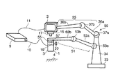
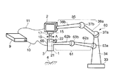
図5及び図6に基づいて本発明の第3の実施形態に係る画像顕微鏡装置を説明する。ただし、上述した第1の実施形態と同一の構成のものには同一の符号を付し、その詳細な説明を省略する。図4は撮像装置と画像表示装置が接続された使用状態の説明図であり、図5は撮像装置と画像表示装置が分離された使用状態の説明図である。
[Third Embodiment]
An image microscope apparatus according to the third embodiment of the present invention will be described with reference to FIGS. However, the same components as those in the first embodiment described above are denoted by the same reference numerals, and detailed description thereof is omitted. FIG. 4 is an explanatory diagram of the usage state in which the imaging device and the image display device are connected, and FIG. 5 is an explanatory diagram of the usage state in which the imaging device and the image display device are separated.
(構成)
本実施形態での撮像装置1及び画像表示装置2は上述した第1の実施形態のものと略同様に構成されるが、本実施形態では一台の保持架台50で撮像装置1及び画像表示装置2の両方を支持できるようにしたものである。
(Constitution)
The
図5に示すように、本実施形態では一台の保持架台60を備える。この保持架台60は上述した第1の実施形態に示した第1保持架台31と同様にベース33と支柱34と支持アーム35とを備える。上記支持アーム35は第1アーム36aと第2アーム36bから構成されている。この支持アーム35の第1アーム36aと支柱34は第1球体軸受37aによって可動が可能な状態で連結され、また、第1アーム36aと第2アーム36bは第2球体軸受37bによって可動が可能な状態で連結されている。この支持アーム35における第2アーム36bの先端に上記画像表示装置2を固着または着脱自在に取り付けるようにした。
As shown in FIG. 5, the present embodiment includes one holding
本実施形態の保持架台60ではその支柱34に対して別の支持アーム61を設け、この別の支持アーム61に上記撮像装置1を支持するようにした。つまり、本実施形態では一台の保持架台60の支柱34に画像表示装置用支持アーム35と撮像装置用支持アーム61の2つの異なる支持アームを設けるようにしたものである。
In the holding
図5及び図6に示すように、上記撮像装置用支持アーム61は第1のアーム62aと第2アーム62bから構成されており、第1アーム62aと支柱34は第1球体軸受63aによって可動が可能に連結され、また、この第1アーム62aと第2アーム62bは第2球体軸受63bによって可動が可能に連結されている。第1球体軸受63a及び第2球体軸受63bにはスイッチによる入力により固定/解除が行われる電磁ブレーキ(図示しない)等が内蔵されている。
As shown in FIGS. 5 and 6, the imaging
この支持アーム61における第2アーム62bの先端には上記画像表示装置2が固着または着脱自在に取り付けられている。ここでは撮像装置1の本体3を着脱自在に取り付ける装着部65と第2アーム62bが一体に構成されている。
The
図6に示すように、支持アーム61における第2アーム62bと一体になった装着部65の上端部には上記画像表示装置2の嵌合軸17を嵌め込める直径Aの嵌合穴19が形成されている。この嵌合穴19に対して上記嵌合軸17を嵌め込み装着すると共に、後述する締付け手段によって所定の位置関係で上記画像表示装置2を接続固定するようになっている。上記締付け手段としては上記嵌合穴19に直交する方向から該嵌合穴19に貫通して上記第2着脱部18に設けられたネジ孔21と、このネジ孔21に螺合する雄ネジ部を有するツマミ22とを含み構成されている。
As shown in FIG. 6, a
(作用)
次に、本実施形態の一使用例について述べる。まず、図5に示すように、上記撮像装置1と、上記画像表示装置2を一体的に組み合わせて使用する場合では、上述した第1の実施形態の場合と同様、画像表示装置用支持アーム35の先端に画像表示装置2を支持し、撮像装置1はその画像表示装置2に対して一体的に組み付けた接続状態にある。さらに、撮像装置1は別の撮像装置用支持アーム61の先端に支持された状態にある。
(Function)
Next, an example of use of this embodiment will be described. First, as shown in FIG. 5, when the
このように上記撮像装置1と上記画像表示装置2を接続して一体的に組み合わせて使用する場合において、被検部4を観察する際、術者はその観察する撮像装置1を左右に移動させたり、或いは被検部4を異なる方向から観察しようとするときは撮像装置1を水平移動させたり傾斜させたりするが、画像表示装置2はその撮像装置1に一体的に固定されているため、この撮像装置1の移動に伴って画像表示装置2も一緒に移動してしまう。従って、画像表示装置2を観察する術者は体を移動或いは傾斜させることになる。
In this way, when the
一方、図6に示すように、上記撮像装置1と上記画像表示装置2を分離して使用する場合においては上記ツマミ22を緩めて上記画像表示装置2側の嵌合軸17を上記撮像装置1側の嵌合穴19から引き抜き、上記撮像装置1を上記画像表示装置2から切り離す。そして、図4に示すように、上記撮像装置1は撮像装置用支持アーム61に支持し、上記画像表示装置2は画像表示装置用支持アーム35に支持する。撮像装置1と画像表示装置2は独立的に別々に動かすことができる。
On the other hand, as shown in FIG. 6, when the
そして、図6に示すように、上記撮像装置1と上記画像表示装置2を分離して、上記撮像装置1と上記画像表示装置2を別々に支持する場合において、術者が被検部4を観察する際、その撮像装置1を左右に移動させる。また、被検部4を撮像観察方向とは異なる方向から観察しようとする場合には撮像装置用支持アーム61の有する球体軸受63a,63bの可動域を利用して撮像装置1を水平移動させたり傾斜させたりする。しかし、画像表示装置2はその撮像装置1から分離されているため、画像表示装置2は撮像装置1の移動には関係なく、その状態を保っている。従って、画像表示装置2を観察する術者は姿勢を変える必要がない。また、術者は画像表示装置2の配置を変えたい場合、画像表示装置用支持アーム35を動かすことによって、撮像装置1と画像表示装置2は独立してその配置を変えることができる。
Then, as shown in FIG. 6, when the
(効果)
本実施形態によれば、ツマミ22を緩めて嵌合軸17を抜き出すだけで簡単に撮像装置1と画像表示装置2を接続された状態から分離された状態に変更することができるので、上述した第1の実施形態及び第2の実施形態によって得られる効果に加えて、術中であっても容易に両者の使い分けが可能となる。
(effect)
According to this embodiment, the
なお、本発明は、前述した実施形態のものに限定されるものではなく、他の形態にも適用が可能である。また、前述した説明によれば、以下の事項またはそれらの事項を組み合わせた事項の発明が得られる。 The present invention is not limited to the embodiment described above, and can be applied to other forms. Further, according to the above description, the invention of the following items or a combination of these items can be obtained.
付記1.被検部を撮像する撮像装置と、上記撮像装置によって撮像した画像を表示する画像表示装置と、上記撮像装置及び上記画像表示装置同士を着脱自在となるよう接続する着脱式接続手段と、を具備したことを特徴とする画像顕微鏡装置。
付記2.上記撮像装置と上記画像表示装置は各々異なる支持アームにて支持されることを特徴とする付記2に記載の画像顕微鏡装置。
付記3.上記各支持アームは共通の支柱に配設されていることを特徴とする付記2に記載の画像顕微鏡装置。
付記4.上記着脱手段は上記支持アームの少なくとも1つと着脱の互換性を有することを特徴とする付記2に記載の画像顕微鏡装置。
付記5.上記支持アームの少なくとも1つは上記撮像装置と上記画像表示装置の何れか一方と一体或いは着脱可能であると共に、他方と着脱可能であることを特徴とする付記2に記載の画像顕微鏡装置。
付記6.上記支持アームの少なくとも1つは先端に支持する装置の重量に相当する反力を有するバランスアームからなると共に、該バランスアームは上記撮像装置と上記画像表示装置との着脱の有無に対して上記反力を変更する反力変更手段を備えることを特徴とする付記2に記載の画像顕微鏡装置。
Appendix 5. 3. The image microscope apparatus according to
1…撮像装置、2…画像表示装置、3…本体、4…被検部、15…着脱部
16…装置本体、17…嵌合軸、18…着脱部、19…嵌合穴
31…保持架台、32…保持架台、35…画像表示装置用支持アーム
61…撮像装置用支持アーム。
DESCRIPTION OF
Claims (3)
上記撮像装置によって撮像した画像を表示する画像表示装置と、
上記撮像装置及び上記画像表示装置同士を着脱自在となるよう接続する着脱式接続手段と、
を具備したことを特徴とする画像顕微鏡装置。 An imaging device for imaging a test portion;
An image display device for displaying an image captured by the imaging device;
Removable connection means for connecting the imaging device and the image display device so as to be detachable;
An image microscope apparatus comprising:
Priority Applications (3)
| Application Number | Priority Date | Filing Date | Title |
|---|---|---|---|
| JP2004104957A JP2005292320A (en) | 2004-03-31 | 2004-03-31 | Image microscopic device |
| US11/095,389 US8265734B2 (en) | 2004-03-31 | 2005-03-31 | Imaging and displaying system with imaging unit and display unit which are supported by movable arm |
| EP05007074A EP1582167B1 (en) | 2004-03-31 | 2005-03-31 | Imaging and displaying system with imaging unit and display unit which are supported by movable arm |
Applications Claiming Priority (1)
| Application Number | Priority Date | Filing Date | Title |
|---|---|---|---|
| JP2004104957A JP2005292320A (en) | 2004-03-31 | 2004-03-31 | Image microscopic device |
Publications (1)
| Publication Number | Publication Date |
|---|---|
| JP2005292320A true JP2005292320A (en) | 2005-10-20 |
Family
ID=34880063
Family Applications (1)
| Application Number | Title | Priority Date | Filing Date |
|---|---|---|---|
| JP2004104957A Pending JP2005292320A (en) | 2004-03-31 | 2004-03-31 | Image microscopic device |
Country Status (3)
| Country | Link |
|---|---|
| US (1) | US8265734B2 (en) |
| EP (1) | EP1582167B1 (en) |
| JP (1) | JP2005292320A (en) |
Cited By (3)
| Publication number | Priority date | Publication date | Assignee | Title |
|---|---|---|---|---|
| JP2010511902A (en) * | 2006-12-07 | 2010-04-15 | スイス メディカル テヒノロギー ゲーエムベーハー | Support system and method for viewer-dependent positioning and alignment of display unit |
| WO2016043046A1 (en) * | 2014-09-16 | 2016-03-24 | ソニー・オリンパスメディカルソリューションズ株式会社 | Medical observation device and medical observation system |
| JPWO2016152987A1 (en) * | 2015-03-25 | 2018-01-18 | ソニー・オリンパスメディカルソリューションズ株式会社 | Medical observation apparatus, surgical observation apparatus, and medical observation system |
Families Citing this family (14)
| Publication number | Priority date | Publication date | Assignee | Title |
|---|---|---|---|---|
| KR101015670B1 (en) * | 2005-09-30 | 2011-02-22 | 레스토레이션 로보틱스, 인코포레이티드 | Automated apparatus for harvesting and implanting follicular units |
| US7946546B2 (en) * | 2006-10-20 | 2011-05-24 | Carnegie Mellon University | Apparatus for positioning a device |
| US7593219B2 (en) * | 2007-04-26 | 2009-09-22 | Hewlett-Packard Development Company, L.P. | Display support system and method |
| US8982203B2 (en) | 2007-06-06 | 2015-03-17 | Karl Storz Gmbh & Co. Kg | Video system for viewing an object on a body |
| US8632064B2 (en) * | 2009-07-15 | 2014-01-21 | The Board Of Trustees Of The Leland Stanford Junior University | Positioning apparatus with lockable joints and method of use |
| CN102778750B (en) * | 2012-07-20 | 2014-06-25 | 中国地质大学(武汉) | Microscope experiment teaching and displaying system |
| JP6214186B2 (en) * | 2013-03-29 | 2017-10-18 | キヤノン株式会社 | Radiation generating apparatus and radiation imaging apparatus |
| WO2015022008A1 (en) * | 2013-08-12 | 2015-02-19 | Schunk Bahn- Und Industrietechnik Gmbh | Current transmission device |
| DE102013226288A1 (en) * | 2013-12-17 | 2015-06-18 | Carl Zeiss Meditec Ag | surgical microscope |
| JP6858593B2 (en) * | 2017-03-02 | 2021-04-14 | ソニー・オリンパスメディカルソリューションズ株式会社 | Medical observation device and control method |
| CN110131532A (en) * | 2018-02-08 | 2019-08-16 | 泰科电子(上海)有限公司 | Imaging device |
| CN110068919A (en) * | 2019-05-29 | 2019-07-30 | 苏州四海通仪器有限公司 | A kind of detachable surgical operation microscope |
| US11448868B2 (en) | 2020-05-07 | 2022-09-20 | Kgg Inc | Ergonomic EZ scope digital imaging system |
| US20230296121A1 (en) * | 2022-03-17 | 2023-09-21 | Mako Surgical Corp. | Techniques For Securing Together Components Of One Or More Surgical Carts |
Citations (3)
| Publication number | Priority date | Publication date | Assignee | Title |
|---|---|---|---|---|
| JPH09102899A (en) * | 1995-10-05 | 1997-04-15 | Scala Kk | Video camera for microscope and video equipment for microscope |
| JPH10179503A (en) * | 1996-12-26 | 1998-07-07 | Asahi Optical Co Ltd | Endoscope device for operation |
| JP2003250812A (en) * | 2002-02-28 | 2003-09-09 | Olympus Optical Co Ltd | Stereoscopic display device for medical treatment |
Family Cites Families (29)
| Publication number | Priority date | Publication date | Assignee | Title |
|---|---|---|---|---|
| DE7930125U1 (en) | 1979-07-24 | 1980-01-24 | Contraves Ag, Zuerich (Schweiz) | ADDITIONAL DEVICE ON A TRIPOD FOR AN OPTICAL OBSERVATION DEVICE |
| JPS6070350A (en) * | 1983-09-28 | 1985-04-22 | Hitachi Ltd | Focal distance confirming method and apparatus therefor |
| JPS6098352A (en) * | 1983-11-02 | 1985-06-01 | Olympus Optical Co Ltd | Ultrasonic microscope |
| US4741607A (en) | 1986-03-17 | 1988-05-03 | Contraves Ag | Supporting device for an optical observation instrument |
| US4863133A (en) * | 1987-05-26 | 1989-09-05 | Leonard Medical | Arm device for adjustable positioning of a medical instrument or the like |
| JPS63296746A (en) | 1987-05-29 | 1988-12-02 | Mitaka Koki Kk | Stand apparatus of medical optical machinery |
| FR2651668B1 (en) * | 1989-09-12 | 1991-12-27 | Leon Claude | MICROSCOPE-ENDOSCOPE ASSEMBLY USEFUL IN PARTICULAR IN SURGERY. |
| US5762458A (en) * | 1996-02-20 | 1998-06-09 | Computer Motion, Inc. | Method and apparatus for performing minimally invasive cardiac procedures |
| US5579772A (en) * | 1993-06-14 | 1996-12-03 | Olympus Optical Co., Ltd. | Surgical microscope system |
| US6106456A (en) * | 1995-02-20 | 2000-08-22 | Karl Storz Gmbh & Co. Kg | Device for examining cavities using an endoscope |
| WO1997015144A1 (en) | 1995-10-20 | 1997-04-24 | Urohealth Systems, Inc. | Hand-held imaging apparatus for use with endoscopes |
| US5855583A (en) * | 1996-02-20 | 1999-01-05 | Computer Motion, Inc. | Method and apparatus for performing minimally invasive cardiac procedures |
| JPH09238951A (en) * | 1996-03-06 | 1997-09-16 | Topcon Corp | Microscope apparatus for surgery |
| US6575908B2 (en) * | 1996-06-28 | 2003-06-10 | Sonosite, Inc. | Balance body ultrasound system |
| US5999837A (en) * | 1997-09-26 | 1999-12-07 | Picker International, Inc. | Localizing and orienting probe for view devices |
| WO1999058044A1 (en) | 1998-05-13 | 1999-11-18 | Inbae Yoon | Penetrating endoscope and endoscopic surgical instrument with cmos image sensor and display |
| US6419626B1 (en) * | 1998-08-12 | 2002-07-16 | Inbae Yoon | Surgical instrument endoscope with CMOS image sensor and physical parameter sensor |
| JP4101951B2 (en) * | 1998-11-10 | 2008-06-18 | オリンパス株式会社 | Surgical microscope |
| US6398721B1 (en) * | 1999-02-19 | 2002-06-04 | Olympus Optical Co., Ltd. | Surgical microscope apparatus |
| US6447451B1 (en) * | 1999-05-04 | 2002-09-10 | Sonosite, Inc. | Mobile ultrasound diagnostic instrument and docking stand |
| JP4611491B2 (en) | 1999-05-31 | 2011-01-12 | Hoya株式会社 | Video stereo microscope |
| JP4245750B2 (en) * | 1999-10-15 | 2009-04-02 | オリンパス株式会社 | Stereoscopic observation device |
| JP2001224595A (en) * | 1999-12-08 | 2001-08-21 | Olympus Optical Co Ltd | Ultrasonic probe for microscopic operation |
| JP4353668B2 (en) | 1999-12-23 | 2009-10-28 | ヒル−ロム サービシズ,インコーポレイテッド | Surgical theater system |
| JP2001276092A (en) | 2000-03-30 | 2001-10-09 | Konan Medical Inc | Simple type medical microscope |
| JP2002006228A (en) | 2000-06-23 | 2002-01-09 | Asahi Optical Co Ltd | Video type microscope for surgery |
| JP3791907B2 (en) * | 2002-02-12 | 2006-06-28 | オリンパス株式会社 | Observation device |
| JP4073249B2 (en) * | 2002-05-17 | 2008-04-09 | オリンパス株式会社 | Surgery system |
| JP4398352B2 (en) * | 2004-12-02 | 2010-01-13 | オリンパス株式会社 | Medical stereoscopic imaging device |
-
2004
- 2004-03-31 JP JP2004104957A patent/JP2005292320A/en active Pending
-
2005
- 2005-03-31 US US11/095,389 patent/US8265734B2/en active Active
- 2005-03-31 EP EP05007074A patent/EP1582167B1/en not_active Expired - Fee Related
Patent Citations (3)
| Publication number | Priority date | Publication date | Assignee | Title |
|---|---|---|---|---|
| JPH09102899A (en) * | 1995-10-05 | 1997-04-15 | Scala Kk | Video camera for microscope and video equipment for microscope |
| JPH10179503A (en) * | 1996-12-26 | 1998-07-07 | Asahi Optical Co Ltd | Endoscope device for operation |
| JP2003250812A (en) * | 2002-02-28 | 2003-09-09 | Olympus Optical Co Ltd | Stereoscopic display device for medical treatment |
Cited By (7)
| Publication number | Priority date | Publication date | Assignee | Title |
|---|---|---|---|---|
| JP2010511902A (en) * | 2006-12-07 | 2010-04-15 | スイス メディカル テヒノロギー ゲーエムベーハー | Support system and method for viewer-dependent positioning and alignment of display unit |
| WO2016043046A1 (en) * | 2014-09-16 | 2016-03-24 | ソニー・オリンパスメディカルソリューションズ株式会社 | Medical observation device and medical observation system |
| US20170227753A1 (en) | 2014-09-16 | 2017-08-10 | Sony Olympus Medical Solutions Inc. | Medical observation apparatus and medical observation system |
| US10114208B2 (en) | 2014-09-16 | 2018-10-30 | Sony Olympus Medical Solutions Inc. | Medical observation apparatus and medical observation system |
| US10634896B2 (en) | 2014-09-16 | 2020-04-28 | Sony Olympus Medical Solutions Inc. | Medical observation apparatus and medical observation system that convert an imaging signal to an optical signal |
| JPWO2016152987A1 (en) * | 2015-03-25 | 2018-01-18 | ソニー・オリンパスメディカルソリューションズ株式会社 | Medical observation apparatus, surgical observation apparatus, and medical observation system |
| US10925685B2 (en) | 2015-03-25 | 2021-02-23 | Sony Olympus Medical Solutions Inc. | Medical observation device, surgical observation device, and medical observation system |
Also Published As
| Publication number | Publication date |
|---|---|
| US8265734B2 (en) | 2012-09-11 |
| EP1582167B1 (en) | 2013-02-27 |
| US20050228257A1 (en) | 2005-10-13 |
| EP1582167A2 (en) | 2005-10-05 |
| EP1582167A3 (en) | 2010-04-21 |
Similar Documents
| Publication | Publication Date | Title |
|---|---|---|
| EP1582167B1 (en) | Imaging and displaying system with imaging unit and display unit which are supported by movable arm | |
| EP3420878B1 (en) | Information processing device for medical use, information processing method, information processing system for medical use | |
| JP5265818B2 (en) | Medical holding device | |
| JP2004181229A (en) | System and method for supporting remote operation | |
| JP2010528762A (en) | Video system for viewing objects on the body | |
| JP3402797B2 (en) | Endoscope image display system | |
| JP2019162231A (en) | Medical imaging device and medical observation system | |
| JP4716545B2 (en) | Surgical microscope equipment | |
| WO2017169650A1 (en) | Medical observation device, image movement correcting method, and medical observation system | |
| EP3603562B1 (en) | Medical observation apparatus and observation field correction method | |
| JP2014076204A (en) | Medical observation system | |
| JP4383188B2 (en) | Stereoscopic observation system | |
| JP7115467B2 (en) | SURGERY IMAGE PROCESSING APPARATUS, IMAGE PROCESSING METHOD, AND SURGERY SYSTEM | |
| JP4426770B2 (en) | Endoscope holding device | |
| JP2001208978A (en) | Microscope system for surgical operation | |
| JP6656237B2 (en) | Surgical microscope device and surgical microscope system | |
| JPH0970406A (en) | Observation device for operation | |
| JP2002125219A (en) | System controller | |
| WO2018043205A1 (en) | Medical image processing device, medical image processing method, and program | |
| JP2001145003A (en) | Image pickup device for endoscope | |
| JP7307986B1 (en) | microscope | |
| JP2000262458A (en) | Operation observing image pickup system | |
| JPH0716238A (en) | Holding device | |
| JP2001111991A (en) | Face-mounted video display device | |
| JP4077682B2 (en) | Surgical observation device |
Legal Events
| Date | Code | Title | Description |
|---|---|---|---|
| A621 | Written request for application examination |
Free format text: JAPANESE INTERMEDIATE CODE: A621 Effective date: 20070119 |
|
| A131 | Notification of reasons for refusal |
Free format text: JAPANESE INTERMEDIATE CODE: A131 Effective date: 20100316 |
|
| A521 | Written amendment |
Free format text: JAPANESE INTERMEDIATE CODE: A523 Effective date: 20100514 |
|
| A02 | Decision of refusal |
Free format text: JAPANESE INTERMEDIATE CODE: A02 Effective date: 20101124 |
|
| A521 | Written amendment |
Free format text: JAPANESE INTERMEDIATE CODE: A523 Effective date: 20110223 |
|
| A911 | Transfer to examiner for re-examination before appeal (zenchi) |
Free format text: JAPANESE INTERMEDIATE CODE: A911 Effective date: 20110303 |
|
| A912 | Re-examination (zenchi) completed and case transferred to appeal board |
Free format text: JAPANESE INTERMEDIATE CODE: A912 Effective date: 20110415 |
|
| A521 | Written amendment |
Free format text: JAPANESE INTERMEDIATE CODE: A523 Effective date: 20120406 |