JP2005216213A - System and method for failure diagnosis - Google Patents
System and method for failure diagnosis Download PDFInfo
- Publication number
- JP2005216213A JP2005216213A JP2004025249A JP2004025249A JP2005216213A JP 2005216213 A JP2005216213 A JP 2005216213A JP 2004025249 A JP2004025249 A JP 2004025249A JP 2004025249 A JP2004025249 A JP 2004025249A JP 2005216213 A JP2005216213 A JP 2005216213A
- Authority
- JP
- Japan
- Prior art keywords
- failure
- control
- output data
- data
- failure diagnosis
- Prior art date
- Legal status (The legal status is an assumption and is not a legal conclusion. Google has not performed a legal analysis and makes no representation as to the accuracy of the status listed.)
- Pending
Links
Images


Abstract
Description
本発明は,ロボットやサーボ、NC装置などのモータを含む制御対象の故障部位の特定や診断等を行う故障診断システム及びその故障診断方法に関する。 The present invention relates to a failure diagnosis system and a failure diagnosis method for identifying and diagnosing a failure portion to be controlled including a motor such as a robot, a servo, and an NC device.
遠隔地にあるユーザの工場に設置されたロボット、サーボ、NC装置などのモータを含む制御対象の故障検出や故障診断を行う場合には、ユーザ側の作業者では十分に対応できない場合がある。それは、工作機械の性能向上に伴うエレクトロニクス化により、制御対象や制御装置の構造ならびに操作システムが複雑化したためであり、故障診断のノウハウを持っていないユーザ側の作業者では膨大な時間を必要とする場合があった。
このため、メーカ側の作業員やユーザの工場近くにあるメーカ側のサービスセンタの作業員が現地に出向く必要があるが、時間と労力とコストがかかっていた。
更に、メーカ側の作業員がユーザの工場で故障検出や故障診断をする場合には、制御対象が設置されている工場のラインを止める必要があるため、ユーザの生産性にも影響が出ていた。また、工場のラインに大型の測定器を持ち込むような場合でも同様に工場のラインを止める必要があった。物理的に狭いラインでは測定器の持ち込みさえ困難な場合があった。
When performing failure detection or failure diagnosis of a control target including a motor such as a robot, a servo, or an NC device installed in a user's factory in a remote place, there may be a case where the user side operator cannot sufficiently cope with it. This is because the structure of the control target and the control device and the operation system have become complicated due to the computerization accompanying the performance improvement of the machine tool, and it requires a huge amount of time for the workers on the user side who do not have the know-how of fault diagnosis. There was a case.
For this reason, it is necessary for workers on the manufacturer's side or workers on the manufacturer's service center near the user's factory to go to the site, but it takes time, labor and cost.
In addition, when a manufacturer's worker performs fault detection or fault diagnosis at the user's factory, it is necessary to stop the factory line where the control target is installed, which has an impact on user productivity. It was. Also, even when a large measuring instrument was brought into the factory line, it was necessary to stop the factory line as well. Even with physically narrow lines, it was sometimes difficult to bring measuring instruments.
このような問題に対して、例えば、図16に示すように、メーカの所有する管理コンピュータとユーザの所有する工作機械またはその端末器とを商用通信回線で接続することにより、対話形式で工作機械の定期診断、故障診断ならびに故障の修復を行う方式がある(例えば、特許文献1参照)。
この方式では、ユーザ側から工作機械の定期診断要求や故障診断要求があったときに、メーカの所有する定期診断あるいは故障診断用プログラムを内蔵した管理コンピュータから工作機械またはその端末器へ、商用通信回線を介して定期診断あるいは故障診断用プログラムを送出する。そして、このプログラムを工作機械に於いて実行した結果生成された定期診断あるいは故障診断に要する情報を、再度商用通信回線を介してメーカ側の管理コンピュータにフィードバックする。
管理コンピュータがこの定期診断または故障診断に要する情報に基づき、専用解析プログラムを実行して工作機械の定期診断または故障診断用プログラムを自動解析し、解析結果をユーザ側の工作機械またはその端末器へ商用通信回線を介して送出する。
また、ユーザ側の工作機械またはその端末器とメーカ側の管理コンピュータに定期診断及び故障診断用プログラムのディスプレイ装置を設け、このディスプレイ装置を介して対話形式で定期診断、故障診断および故障修復に要する情報を伝達する構成となっている。
To solve such a problem, for example, as shown in FIG. 16, a machine tool is interactively connected by connecting a management computer owned by the manufacturer and a machine tool owned by the user or a terminal device thereof through a commercial communication line. There are methods for performing periodic diagnosis, failure diagnosis, and repair of failure (see, for example, Patent Document 1).
In this method, when there is a periodic diagnosis request or failure diagnosis request for a machine tool from the user side, commercial communication from the management computer with the periodic diagnosis or failure diagnosis program owned by the manufacturer to the machine tool or its terminal A program for periodic diagnosis or failure diagnosis is sent via the line. Information necessary for periodic diagnosis or failure diagnosis generated as a result of executing this program in the machine tool is fed back to the management computer on the manufacturer side again via the commercial communication line.
Based on the information required for periodic diagnosis or failure diagnosis by the management computer, the dedicated analysis program is executed to automatically analyze the machine tool periodic diagnosis or failure diagnosis program, and the analysis result is sent to the user machine tool or its terminal. Send out via commercial communication line.
In addition, a display device for a periodic diagnosis and failure diagnosis program is provided in the machine tool on the user side or its terminal and the management computer on the manufacturer side, and it is necessary for periodic diagnosis, failure diagnosis and failure repair in an interactive manner via this display device. It is configured to transmit information.
また、ロボットの動作波形を診断するため、ロボットの動作データの波形を記憶し、基準波形と比較して特徴量を抽出する装置が開示されている(例えば、特許文献2参照)。
この装置では、ロボットの動作データの履歴を記憶するデータファイルと、基準波形と比較して、取り込んだ動作データの波形の特徴量を抽出する波形特徴抽出部と、基準波形と特徴量とからモデル化された標準データを作成する標準データ作成部と、標準データを動作データに合わせて調整する標準データ調整部と、調整された標準データと動作データを比較して予め設定された波形診断用コメントテーブルをルックアップしながら動作データの波形診断を行う波形診断部とを有しロボットコントローラと通信を行うワークステーションと、ロボットコントローラとを接続する。
Also, an apparatus is disclosed that stores a waveform of robot motion data and extracts a feature amount compared with a reference waveform in order to diagnose a robot motion waveform (see, for example, Patent Document 2).
In this apparatus, a data file that stores a history of robot motion data, a waveform feature extraction unit that extracts the feature amount of the captured motion data waveform compared to the reference waveform, and a model from the reference waveform and feature amount Standard data creation unit that creates standardized data, standard data adjustment unit that adjusts standard data according to operation data, and comments for waveform diagnosis that are set in advance by comparing the adjusted standard data and operation data The robot controller is connected to a workstation having a waveform diagnosis unit for performing waveform diagnosis of operation data while looking up the table and communicating with the robot controller.
ところが、対話形式で工作機械の定期診断、故障診断ならびに故障の修復を行う方式では、定期診断または故障診断用のプログラムや専用解析プログラムの実行が必要であり、制御対象や制御装置が変更になると対応できないという問題があった。また、定期診断や故障診断を行う際に工場のラインを止める必要があるという問題は依然として残っていた。
また、対話形式ではユーザ側の作業者が不在の場合には対応できず時間のロスが発生し、制御対象がプレイバック運転中には一切の処理を行うことができず、定期診断や故障診断の自動化、故障部位の特定にも対応できなかった。さらには故障診断を実行するために常時複雑な専用解析プログラムを実行する必要があり、CPUパワー及び膨大な演算時間を必要とするという問題もあった。
一方、ロボットの動作データの波形を記憶し、基準波形と比較して特徴量を抽出する方式では、基準波形と比較することでロボットの動作データから特徴量を抽出して波形診断用コメントテーブルをルックアップしているが、動作データの抽出とその波形の自動判断だけであるため、上記方式と同様に、故障部位の特定ができる構成になっていなかった。また、所定の動作でしか動作データの波形を取ることができないため、ユーザ側の作業者が作成した作業プログラムによるプレイバック運転中の定期診断や故障診断には対応することができない。さらに上記方式と同様、データを抽出するためにCPUパワー及び膨大な演算時間を必要とするという問題もあった。
However, the method of performing periodic diagnosis, failure diagnosis, and repair of machine tools in an interactive format requires the execution of periodic diagnosis or failure diagnosis programs and dedicated analysis programs, and the controlled objects and control devices change. There was a problem that could not be handled. In addition, the problem of having to stop the factory line when performing periodic diagnosis and failure diagnosis still remained.
Also, in the interactive format, when there is no user side worker, it is not possible to cope with the loss of time, the control target cannot perform any processing during playback operation, periodic diagnosis and failure diagnosis It was not possible to deal with the automation of and the identification of the failure part. Furthermore, it is necessary to always execute a complicated dedicated analysis program in order to execute failure diagnosis, and there is a problem that it requires CPU power and enormous calculation time.
On the other hand, in the method of storing the robot motion data waveform and extracting the feature value compared with the reference waveform, the feature value is extracted from the robot motion data by comparing with the reference waveform, and a comment table for waveform diagnosis is created. Although it is looked up, since it is only extraction of operation data and automatic judgment of its waveform, it has not been configured to be able to identify a faulty part as in the above method. Further, since the waveform of the operation data can be obtained only by a predetermined operation, it is not possible to cope with a periodic diagnosis or a failure diagnosis during playback operation by a work program created by a user-side worker. Further, like the above method, there is a problem that CPU power and enormous calculation time are required to extract data.
そこで本発明は、遠隔地からでも制御対象や制御装置の故障診断及び故障部位の特定を時間のロスなく簡単に行え、工場のラインを止めず、通常のプレイバック運転時にも故障診断を行うことができる故障診断システム及び故障診断方法を提供することを目的とする。 In view of this, the present invention can easily perform failure diagnosis and control of a control object or control device even from a remote location without loss of time, and perform failure diagnosis even during normal playback operation without stopping the factory line. It is an object of the present invention to provide a failure diagnosis system and a failure diagnosis method capable of performing the above.
本発明では、上記問題点を解決するため、以下のように構成したのである。
請求項1に記載の発明は、モータを含む制御対象への入力データを生成する指令生成部と、前記入力データ及び前記制御対象の出力データを記憶するデータ記憶部を備えた制御装置と、前記制御対象を模擬した制御モデルを有し、前記制御モデルと前記入力データ及び前記出力データとから前記制御対象の故障を診断し故障部位を特定する故障判定部を備えた故障診断部と、前記制御装置と前記故障診断部とを接続する通信路とから構成されることを特徴とする故障診断システムである。
請求項2に記載の発明は、前記入力データは、前記制御対象への指令であり、前記出力データは前記指令に対する前記制御対象の応答であることを特徴とする請求項1記載の故障診断システムである。
請求項3に記載の発明は、前記データ記憶部は、前記入力データ及び前記出力データを前記故障診断部に送信し、前記故障判定部は、前記出力データと、前記入力データに対する前記制御モデルの出力データとを比較することで、故障診断することを特徴とする請求項1又は2記載の故障診断システムである。
請求項4に記載の発明は、前記故障判定部は、前記制御対象を故障と診断した場合に、
前記制御対象及び前記制御モデルをそれらのハードウェア又はソフトウェアの構成によって複数個のモジュールに分割し、前記データ記憶部は前記分割された制御対象への各入力データ及び前記分割された制御対象の各出力データを前記故障診断部に送信し、前記故障判定部は、前記各出力データと、前記各入力データに対する前記分割された制御モデルの各出力データとを比較することで、前記制御対象の故障部位を特定することを特徴とする請求項1乃至3記載の故障診断システムである。
請求項5に記載の発明は、前記制御装置又は前記故障診断部は、前記入力データと前記出力データ及び前記制御モデルの出力データを表示する表示画面を備えることを特徴とする請求項1乃至4記載の故障診断システムである。
請求項6に記載の発明は、前記制御装置又は前記故障診断部は、故障部位を特定する過程及び特定された故障部位を文字又は図形で表示する表示画面を備えることを特徴とする請求項1乃至5記載の故障診断システムである。
請求項7に記載の発明は、前記故障診断部は、履歴記憶部を備え、前記履歴記憶部は、特定された故障部位を記録し、前記表示画面に故障履歴を表示することを特徴とする請求項5又は6記載の故障診断システムである。
請求項8に記載の発明は、前記故障診断部は、前記制御対象の故障部位を特定する際に複数の候補が挙がった場合、前記履歴記憶部に記憶された故障履歴又は予め設定された順位により、故障部位を特定することを特徴とする請求項7記載の故障診断システムである。
請求項9に記載の発明は、前記履歴記憶部は、前記出力データと前記制御モデルの出力データとの差分値を一定周期毎に記憶し、前記差分値の時間差分と予め設定されたしきい値とを比較することで、前記制御対象の故障を予想し、前記表示画面に警告を表示することを特徴とする請求項7又は8記載の故障診断システムである。
また、請求項10に記載の発明は、モータを含む制御対象を制御する制御システムの故障診断方法において、前記制御対象への入力データ及び前記制御対象の出力データを記憶し、前記制御対象を模擬した制御モデルに前記入力データを入力し、前記出力データと前記制御モデルの出力データとを比較して前記制御対象の故障を診断することを特徴とするものである。
請求項11に記載の発明は、モータを含む制御対象を制御する制御システムの故障診断方法において、前記制御対象への入力データ及び前記制御対象の出力データを記憶し、
前記制御対象を模擬した制御モデルに前記入力データを入力し、前記出力データと前記制御モデルの出力データとを比較して前記制御対象の故障を診断し、故障と診断された場合は前記制御対象及び前記制御モデルをそれらのハードウェア又はソフトウェアの構成によって複数個のモジュールに分割し、前記分割された制御対象への各入力データ及び前記分割された制御対象の各出力データを記憶し、前記分割された制御モデルに前記各入力データを入力し、前記分割された制御対象の各出力データと前記分割された制御モデルの各出力データとを比較して前記制御対象の故障部位を特定することを特徴とするものである。
請求項12に記載の発明は、モータを含む制御対象を制御する制御システムの故障診断方法において、前記出力データと前記制御モデルの出力データとの差分値を一定周期毎に記憶し、前記差分値の時間差分と予め設定されたしきい値とを比較することで、前記制御対象の故障を予想することを特徴とする請求項11又は12記載の故障診断方法である。
The present invention is configured as follows in order to solve the above-described problems.
The invention according to claim 1 is a control device including a command generation unit that generates input data to a control target including a motor, a data storage unit that stores the input data and output data of the control target, and A fault diagnosis unit having a control model simulating a control target, and having a fault determination unit for diagnosing a fault of the control target from the control model, the input data, and the output data and identifying a fault part; and A failure diagnosis system comprising a communication path connecting an apparatus and the failure diagnosis unit.
The invention according to claim 2 is characterized in that the input data is a command to the controlled object, and the output data is a response of the controlled object to the command. It is.
According to a third aspect of the present invention, the data storage unit transmits the input data and the output data to the failure diagnosis unit, and the failure determination unit includes the output data and the control model for the input data. 3. The fault diagnosis system according to claim 1, wherein the fault diagnosis is performed by comparing the output data.
In the invention according to claim 4, when the failure determination unit diagnoses the control target as a failure,
The control object and the control model are divided into a plurality of modules according to their hardware or software configuration, and the data storage unit is configured to input data to the divided control object and each of the divided control objects. The output data is transmitted to the failure diagnosis unit, and the failure determination unit compares each output data with each output data of the divided control model for each input data, thereby the failure of the control target. 4. The fault diagnosis system according to claim 1, wherein a part is specified.
According to a fifth aspect of the present invention, the control device or the failure diagnosis unit includes a display screen that displays the input data, the output data, and the output data of the control model. It is a failure diagnosis system of description.
The invention according to claim 6 is characterized in that the control device or the failure diagnosis unit includes a process of specifying a failure part and a display screen for displaying the specified failure part in characters or graphics. The failure diagnosis system according to any one of claims 5 to 5.
The invention according to claim 7 is characterized in that the failure diagnosis unit includes a history storage unit, and the history storage unit records the specified failure part and displays the failure history on the display screen. The fault diagnosis system according to claim 5 or 6.
In the invention according to claim 8, when a plurality of candidates are listed when the failure diagnosis unit identifies the failure part to be controlled, a failure history stored in the history storage unit or a preset order The fault diagnosis system according to claim 7, wherein a fault site is specified by:
According to a ninth aspect of the present invention, the history storage unit stores a difference value between the output data and the output data of the control model at regular intervals, and a time difference between the difference values and a preset threshold value. 9. The fault diagnosis system according to claim 7, wherein a failure of the control target is predicted by comparing the value and a warning is displayed on the display screen.
According to a tenth aspect of the present invention, in a failure diagnosis method for a control system that controls a control target including a motor, input data to the control target and output data of the control target are stored, and the control target is simulated. The input data is input to the control model, and the output data and the output data of the control model are compared to diagnose a failure of the control target.
The invention according to
The input data is input to a control model simulating the control object, the output data and the output data of the control model are compared to diagnose a failure of the control object, and when the failure is diagnosed, the control object And dividing the control model into a plurality of modules according to their hardware or software configuration, storing each input data to the divided control object and each output data of the divided control object, and the division Each of the input data is input to the control model, and the output data of the divided control target is compared with the output data of the divided control model to identify the faulty part of the control target. It is a feature.
According to a twelfth aspect of the present invention, in a failure diagnosis method for a control system for controlling a control target including a motor, a difference value between the output data and the output data of the control model is stored at a certain period, and the difference value is stored. The failure diagnosis method according to
請求項1、2及び3に記載の故障診断システムによると、制御対象や制御装置の故障診断及び故障部位の特定を遠隔地からや現場でも簡単に時間のロスなく行え、工場のラインを止める必要が無く、通常のプレイバック運転時にも故障診断を行うことができる。また、単純な波形比較だけで良いために特別なノウハウを必要とせず、故障部位の特定を自動的に行える。
請求項4に記載の故障診断システムによると、制御対象と制御モデルを分割して、各入出力を突合せて比較し、故障部位を特定するまで繰返すことにより、より詳細に故障部位を絞り込める。また、制御対象及び制御モデルを複数個に分割する場合に、ソフトウェア又はハードウェアのモジュール単位で分けた部分の入出力データを記憶することにより、ハードウェアによる故障とソフトウェアによる不具合を分離して診断でき、故障部位特定の時間を短縮することができる。
請求項5に記載の故障診断システムによると、入出力データの指令と応答及び制御モデルからの出力を画面に表示することにより、故障部位が特定された場所や条件などの結果を作業者が確認できる。また、故障判断のしきい値を調整する際にも直感的に行うことができる。
請求項6に記載の故障診断システムによると、故障部位を特定する過程及び特定された故障部位を文字又は図形で画面上に表示することにより、作業者が故障の詳細を即座に認識でき、故障に対する対応準備の時間を短縮できる。
請求項7に記載の故障診断システムによると、故障部位を記憶しデータベース化して作業者に提示することにより、故障部位診断の優先順位を簡単に設定することができる。
請求項8に記載の故障診断システムによると、故障部位を特定中に複数の部位が候補に挙がった場合、故障履歴又は予め設定された順位で、故障部位の特定に優先順位を付けることにより、熟練者の蓄積されたノウハウを利用でき、短時間で故障部位の特定ができる。
請求項9記載の故障診断システムによると、制御モデルからの出力と制御対象からの出力の差分値の時間変化を捉えることにより、簡単に故障予想を行うことができる。
請求項10記載の故障診断方法によると、制御対象や制御装置の故障診断及び故障部位の特定を遠隔地からや現場でも簡単に時間のロスなく行え、工場のラインを止める必要が無く、通常のプレイバック運転時にも故障診断を行うことができる。また、単純な波形比較だけで良いために特別なノウハウを必要とせず、故障部位の特定を自動的に行える。
請求項11記載の故障診断方法によると、より詳細に故障部位を絞り込める。
請求項12記載の故障診断方法によると、制御対象や制御装置の故障予想を遠隔地からでも簡単に時間のロスなく行え、工場のラインを止める必要が無い。また、通常のプレイバック運転時にも故障予想を行える。
According to the failure diagnosis system according to claims 1, 2, and 3, it is necessary to easily perform failure diagnosis and identification of a failure to be controlled or a control device from a remote place or at a site without time loss, and to stop the factory line. No failure diagnosis can be performed even during normal playback operation. In addition, since only a simple waveform comparison is required, no special know-how is required, and the failure part can be automatically identified.
According to the fault diagnosis system of the fourth aspect, the control unit and the control model are divided, the input / outputs are compared and compared, and the process is repeated until the faulty part is specified, thereby narrowing down the faulty part in more detail. In addition, when dividing the control target and control model into multiple parts, by storing the input / output data of the software or hardware modules divided in units of modules, it is possible to separate and diagnose hardware failures and software failures It is possible to shorten the time for specifying the faulty part.
According to the failure diagnosis system of claim 5, the operator confirms the result of the location and condition where the failure part is specified by displaying the command and response of the input / output data and the output from the control model on the screen. it can. It can also be done intuitively when adjusting the threshold for failure determination.
According to the fault diagnosis system according to claim 6, the process of identifying the faulty part and displaying the specified faulty part on the screen in characters or graphics, the operator can immediately recognize the details of the fault, The time for preparing for the response can be shortened.
According to the failure diagnosis system of the seventh aspect, the failure site diagnosis can be easily set by storing the failure site, creating a database, and presenting it to the operator.
According to the failure diagnosis system according to claim 8, when a plurality of parts are listed as candidates while specifying the failure part, by giving priority to the specification of the failure part in the failure history or a preset order, The know-how accumulated by skilled workers can be used, and the failure part can be identified in a short time.
According to the failure diagnosis system of the ninth aspect, the failure prediction can be easily performed by grasping the time change of the difference value between the output from the control model and the output from the control target.
According to the failure diagnosis method of
According to the failure diagnosis method of the eleventh aspect, failure parts can be narrowed down in more detail.
According to the failure diagnosis method of the twelfth aspect, it is possible to easily predict a failure of a control target or a control device from a remote place without loss of time, and it is not necessary to stop the factory line. In addition, failure prediction can be performed during normal playback operation.
以下、本発明の実施の形態について図を参照して説明する。 Hereinafter, embodiments of the present invention will be described with reference to the drawings.
本発明の第1の基本構成を図1に、処理の流れを図2に示して説明する。
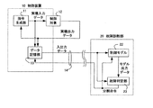
ここでは、ユーザ側に配置されたモータを含む制御対象12と、その制御対象を制御する制御装置10の故障検出及び故障診断方法を、遠隔地のメーカ側の故障診断部20で実施する基本的な処理の流れについて、3ステップに分けて説明する。各ステップは図2に示す処理フローの第1〜3ステップに対応している。
The first basic configuration of the present invention will be described with reference to FIG. 1, and the flow of processing will be described with reference to FIG.
Here, the failure detection unit 20 on the remote manufacturer side performs the failure detection and failure diagnosis method of the
(1)第1ステップ
図1に示すように、制御装置10内の指令生成部11から制御対象12に位置指令や速度指令などの指令データが入力される(以降、この入力データを実機入力データとする)。
制御対象12は実機入力データに基づいて動作し、指令生成部11に位置応答や速度応答などの応答データを出力する(以降、この出力データを実機出力データとする)。
これらの実機入力データと実機出力データは、制御対象12の動作中に所定の周期(例えば、数十ms)毎に、データ記憶部13に記憶される(以降、この実機入力データと実機出力データを合わせて入出力データとする)。
ここで、制御対象12が複数個のモジュールに分割できる構造の場合には、予め各々のモジュールの入出力データをデータ記憶部13に記憶するように構成する。例えば、図5に示すように、3つのモジュール12a、12b、12cが直列に接続されている場合には、モジュール12aの第1の実機出力データをモジュール12bへの実機入力データとし、モジュール12bの第2の実機出力データをモジュール12cへの実機入力データとし、モジュール12cの第3の実機出力データとして、指令生成部11からの実機入力データと書くモジュールの実機出力データ12a、12b、12cをそれぞれ取得して、入出力データとして記憶する。
(1) First Step As shown in FIG. 1, command data such as a position command and a speed command is input from the
The
The actual machine input data and the actual machine output data are stored in the
Here, when the
(2)第2ステップ
入出力データは、電話回線やインターネットのような商用通信回線やLANなどの専用回線、あるいは無線通信などの通信路14を介して、予め決められた一定周期(例えば、1作業や1時間)毎にメーカ側に配置された故障診断部20に送信される。ここで、故障診断部20へ最初に送信されるデータには、制御対象12の機種情報や作業プログラムの内容などが添付されて送られ、故障診断部20内の制御モデル22を制御対象12と同じ設定にする。
(2) Second step The input / output data is transmitted through a
(3)第3ステップ
故障診断部20は、制御対象12を模擬した制御モデル22と、故障を検出及び診断する故障判定部23とを有しており、入出力データと制御モデル22を基に故障判定部23にて故障検出及び診断を行う。
故障診断は、入出力データに含まれる実機入力データを制御モデル22に入力し、制御モデル22から出力される応答データ(以降、この出力データをモデル出力データとする)を求め、故障判定部23で入出力データに含まれる実機出力データとの差分値を求めることで行なう。
制御モデル22は制御対象12の機構の特性などを含んだモータの運動特性を反映しているので、同じ指令を入力すると制御対象12とほぼ同じ出力が得られる。
そのため、制御対象12に故障がない場合には実機出力データとモデル出力データとの差分値は小さくなり、故障がある場合には差分値は大きくなるため、この差分値の絶対値を予め設定されたしきい値と比較し、しきい値より大きい場合は故障とすることで、ノウハウや複雑な解析プログラムを必要とせずに故障を簡単に検出することができる。
(3) Third Step The failure diagnosis unit 20 includes a
In the failure diagnosis, the actual machine input data included in the input / output data is input to the
Since the
For this reason, the difference value between the actual machine output data and the model output data is small when there is no failure in the controlled
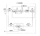
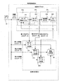
また、前述のように制御対象12が複数のモジュールから構成されている場合には、図6に示すように、予め制御モデルも複数に分割しておき、実機入力データを制御モデル22aに入力し、制御モデル22aから出力される第1のモデル出力データを求め、故障判定部23内の第1のデータ比較部231にて第1の実機出力データとの差分値の絶対値を求め、予め設定されたしきい値と比較する。
同様に、第2の実機入力データを制御モデル22bに入力し、制御モデル22bから出力される第2のモデル出力データを求め、故障判定部23内の第2のデータ比較部232にて第2の実機出力データとの差分値の絶対値を求め、予め設定されたしきい値と比較し、 第3の実機入力データを制御モデル22cに入力し、制御モデル22cから出力される第3のモデル出力データを求め、故障判定部23内の第3のデータ比較部233にてで第3の実機出力データとの差分値の絶対値を求め、予め設定されたしきい値と比較する。
このように、制御対象12が複数のモジュールで構成されている場合には、故障検出された時点で、故障部位の特定まで完了することができる。
Further, as described above, when the
Similarly, the second actual machine input data is input to the
As described above, when the
本発明の第2の基本構成を図3、図5及び図6に、処理の流れを図4に示して説明する。
第1の基本構成では制御対象12が予め複数のモジュールから構成されていたのに対して、この第2の基本構成では故障診断する過程で制御対象12及び制御モデル22をモジュールに分割しながら故障部位を特定する過程を備える。
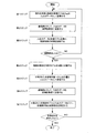
故障検出及び故障診断の方法について、7ステップに分けて説明する。各ステップは図4に示す処理フローの第1〜第7ステップに対応している。故障検出までの過程は図2と同じであるため、説明を省略する。故障が検出された場合には次の第4ステップに進む。
The second basic configuration of the present invention will be described with reference to FIGS. 3, 5 and 6, and the flow of processing will be described with reference to FIG.
In the first basic configuration, the
The failure detection and failure diagnosis method will be described in 7 steps. Each step corresponds to the first to seventh steps of the processing flow shown in FIG. Since the process up to the failure detection is the same as that in FIG. If a failure is detected, the process proceeds to the next fourth step.
(4)第4ステップ
故障判定部23で故障と診断された場合には故障部位を特定する過程に入る。図3に示すように、故障判定部23から制御対象12及び制御モデル22をN個(N:自然数)に分割する命令が送られる。分割命令が送られると、制御対象12及び制御モデル22の応答データを取得する箇所をN箇所に変更し、制御対象12及び制御モデル22の内部状態量をより詳しく比較する。
具体的にはNは、制御対象12を構成する部品のうち、その出力が検出できるよう検出器が取付けられたものの数によって決まる。その数は前述の第2ステップの段階で制御装置10から故障診断部20へと送信しておく。
なお、制御装置10と故障診断部20の間のデータ転送量を極力減らすために制御対象12及び制御モデル22をまずN個に分割したあと、故障部位を詳細に特定する過程でモジュールをさらに複数に分割するという手順をとる。
ハードウェアのモジュール単位で3分割する例として、図5に示すように制御対象12を第1の制御対象12aから第3の制御対象12cまでに分割する。同様に、制御モデル22は、図6に示すように、第1の制御モデル22aから第3の制御モデル22cまでに分割する。以後、制御対象12及び制御モデル22が3個に分割された場合について説明する。
(4) Fourth step When the
Specifically, N is determined by the number of components that constitute the
In addition, in order to reduce the data transfer amount between the
As an example of dividing into three hardware modules, the
(5)第5ステップ
再度、上位からの動作指令に対して動作を実行することで、3個に分割された各制御対象12a、12b、12cの入出力データをデータ記憶部13にそれぞれ記憶する。
または、動作実行毎に各制御対象12a、12b、12cの入出力データを全て記憶しておき、第2ステップの故障検出前には出力端である制御対象12cの応答データのみを故障診断部20に送信し、故障検出後には予め記憶しておいた各制御対象12の3個の応答データを故障診断部20に送信することで、故障発生後の制御対象12の再動作を回避させても良い。
(5) Fifth Step The input / output data of each of the control objects 12a, 12b, and 12c divided into three is stored in the
Alternatively, every time the operation is executed, all the input / output data of the control objects 12a, 12b, and 12c is stored, and only the response data of the
(6)第6ステップ
第2ステップと同様に、通信路14を介して、各制御対象12a、12b、12cから出力された3個の入出力データを故障診断部20に送信する。
(6) Sixth Step Similar to the second step, three pieces of input / output data output from the control objects 12a, 12b, and 12c are transmitted to the failure diagnosis unit 20 via the
(7)第7ステップ
第3ステップと同様に、入出力データと3個に分割された制御モデル22とを基に、制御対象12の故障部位を特定することを繰返す。
具体的には、図6に示すように、入出力データに含まれる実機入力データを第1の制御モデル22aに入力し、第1の制御モデル22aから出力される第1のモデル出力データを求める。更に、第1のモデル出力データを第2の制御モデル22bに入力し、第2の制御モデル22bから出力される第2のモデル出力データを求める。更に、第2のモデル出力データを第3の制御モデル22cに入力し、第3の制御モデル22cから出力される第3のモデル出力データを求める。
故障判定部23において、3個のモデル出力データと入出力データに含まれる3個の実機出力データの各々の差分値の絶対値を取り、予め設定されたしきい値と比較することで、故障部位の特定を行う。
(7) Seventh Step Similar to the third step, the identification of the failure part of the controlled
Specifically, as shown in FIG. 6, the actual machine input data included in the input / output data is input to the
In the
差分値の絶対値がしきい値を上回るモジュールが複数あって、故障部位を特定できない場合には、後述する優先順位に従って優先順位の高いモジュールについて故障部位の特定を行なうこととし、第4ステップに戻って優先順位の高いモジュールを更に分割し、故障部位を特定するための処理を繰返す。
故障部位を特定できた場合には故障診断を終了し、後述する表示部によってユーザ側の制御装置10を操作している作業者及びメーカ側の故障診断部20を操作している作業者に故障部位及び交換方法などを知らせる。
When there are a plurality of modules whose absolute value of the difference value exceeds the threshold value and the failure part cannot be specified, the failure part is specified for a module having a high priority according to the priority order described later, and the fourth step is performed. Returning, the module with higher priority is further divided, and the process for specifying the faulty part is repeated.
When the failure part can be identified, the failure diagnosis is terminated, and the operator who operates the
以上の処理は、通常の動作指令に対する実機とモデルの応答波形の比較で良いため、故障検出や故障診断のための特別な動作を行わずに済み、故障部位を特定するまで工場のラインを停止させる必要もなく、遠隔地からの故障診断を行える。また、単純な波形の比較であるため、簡単に自動化できる。更には、通常の故障検出までは制御装置10と故障診断部20間の通信データ量が少なくて済む。
Since the above processing can be performed by comparing the response waveforms of the actual machine and model to normal operation commands, there is no need to perform special operations for fault detection or fault diagnosis, and the factory line is stopped until the fault location is specified. Failure diagnosis can be performed from a remote location. Also, since it is a simple waveform comparison, it can be easily automated. Furthermore, the amount of communication data between the
本発明の第1の具体的実施例を図7〜図11に示して説明する。本実施例では、制御対象は図7に示すように減速機を介したモータにより各軸を駆動する垂直多関節型の6軸ロボット30とし、ロボット30はその手先に溶接冶具31を持つ。また、ロボット30を制御する制御装置10には作業者がロボット30を操作するための操作ペンダント15が接続されている。
本実施例では、ロボット30の故障部位は根元から4軸目のモータに接続された減速機であり、この減速機が摩耗により歯飛びしたと想定して、この故障部位を遠隔地のメーカ側に配置された故障診断部20で特定する過程を説明する。簡略化のため、第4軸の関節軸の制御系に着目して説明を進める。
また、ロボット30の各軸にあたる制御対象12は図8に示すように、指令生成部11から出力される動作指令からモータ122に対するトルク指令又は電流指令を生成するモータ制御部121と、トルク指令又は電流指令により駆動されるモータ122と、モータ122の状態量を検出する第1検出器123と、モータ122の駆動力を倍増させる減速機124と、減速機124に接続されたメカ125と、メカ125の状態量を検出する第2検出器126で構成されている。
図4の処理フローで説明したように、故障部位の特定過程は7ステップに分かれており、第1〜3ステップでは故障検出及び大まかな故障部位特定を実行し、第4〜7ステップでは詳細な故障部位特定を実行する。以下に詳細を説明する。
A first specific embodiment of the present invention will be described with reference to FIGS. In this embodiment, the control target is a vertical articulated 6-
In this embodiment, the failure part of the
Further, as shown in FIG. 8, the
As described in the processing flow of FIG. 4, the fault site identification process is divided into seven steps. In the first to third steps, fault detection and rough fault site identification are executed, and in the fourth to seventh steps, detailed processing is performed. Execute fault location identification. Details will be described below.
(1)第1ステップ
始めに、故障が発生していない状態から、故障の発生、その故障を検出するまでの過程を説明する。
例えばユーザ側に配置されたロボットを用いて溶接作業を行う場合、予め制御装置10に記憶されている位置指令を指令生成部11から制御対象12に送ることで、ロボット30は教示通りの溶接作業を行う。
図8に示すように、位置指令は制御対象12内のモータ制御部121に送られ、モータ制御部121は駆動源であるモータ122に対して、トルク指令又は電流指令を出力する。
モータ122の出力は位置であり、減速機124への入力となる。減速機124の出力も位置であり、メカ125への入力となる。メカ125の出力も位置となり、第2検出器126で検出することができる。第2検出器の出力を指令生成部11へ返信する。
ここで、制御対象12に対する位置指令を実機入力データとし、第2検出器126の出力である位置応答を実機出力データとする。これらの実機入出力データは、データ記憶部13で、6軸分の入出力データとして予め決められた一定周期(ここではトルク指令又は電流指令の演算周期時間)毎に記憶される。
(1) First Step First, the process from the occurrence of no failure to the occurrence of the failure and the detection of the failure will be described.
For example, when welding work is performed using a robot arranged on the user side, the
As shown in FIG. 8, the position command is sent to the
The output of the
Here, the position command for the controlled
(2)第2ステップ
入出力データは、インターネットなどの通信路14により、第1ステップとは異なる予め決められた一定周期(ここでは1つのワークを溶接する周期とする)毎に、遠隔地にあるメーカ側の故障診断部20に送信される。ここで、最初に送信されるデータには、故障診断部20内の制御モデル22を制御対象12と同じ設定にするため、ロボットの機種情報(6軸各々のイナーシャ値、演算周期時間など)や作業プログラムの内容などが添付される。
(2) Second step Input / output data is transmitted to a remote place at a predetermined fixed period (here, one workpiece is welded) different from the first step by a
(3)第3ステップ
故障診断部20では、故障診断の開始時に図9に示すように、制御対象12を模擬した制御モデル22を作成する。制御モデル22は、実機の制御対象12の内、モータ制御部121を模擬したモータ制御モデル221と、モータ122を模擬したモータモデル222と、減速機124を模擬した減速機モデル224と、メカ125を模擬したメカモデル225で構成される。
ここで、演算量を削減するために、故障検出するまではメカモデル225を剛体として扱い、故障検出後には、故障部位を特定するために多慣性モデルとして扱う。よって、ここでは剛体モデルとして演算する。
実機入力データθrefを制御モデル22に入力することで、モータモデル222の出力であるモデル出力データθfbmを得ることができる。この演算は、以下の(式1)〜(式3)で行なう。(式1)は、実機のモータ制御部121で演算するソフトウェアと同一の演算で、制御パラメータも同一で良いため、複雑な解析アルゴリズムが不要である。
(3) Third step The failure diagnosis unit 20 creates a
Here, in order to reduce the amount of calculation, the
By inputting actual machine input data θref to the
Trefm = J*Kv*( Kp*(θref − θfbm ) − ・θfbm) ・・・(式1)
ここで、
Trefm:モデルトルク指令
J:モータのロータイナーシャ+機構部のイナーシャ(減速機を含む)
Kv:速度ループゲイン
Kp:位置ループゲイン
θref:指令生成部11から位置指令(実機入力データ)
θfbm:モデル位置応答(モデル出力データ)
・θfbm:モデル速度応答
Trefm = J * Kv * (Kp * (θref − θfbm) − • θfbm) (Equation 1)
here,
Trefm: Model torque command J: Motor rotor inertia + mechanism inertia (including reduction gear)
Kv: Speed loop gain
Kp: Position loop gain θref: Position command from command generator 11 (actual machine input data)
θfbm: Model position response (model output data)
・ Θfbm: Model speed response
・θfbm = Σ( dt * Trefm / J ) ・・・(式2)
ここで、
Σ:積分
dt:演算周期時間
・ Θfbm = Σ (dt * Trefm / J) (Formula 2)
here,
Σ: integral
dt: Calculation cycle time
θfbm = Σ( dt * ・θfbm ) ・・・(式3) θfbm = Σ (dt * · θfbm) (Equation 3)
ここで、剛体モデルのイナーシャJの演算値は、実機のモータ制御部121での演算結果を定期的に故障診断部20側へ送っても良く、又は入出力データに含まれる実機の位置応答θfbから故障診断部20側で計算しても良い。同様に粘性摩擦なども、実動作で測定された摩擦値を定期的に故障診断部20側に送ることで、実機とモデルの状態量をより一致させても良い。
故障診断は、入出力データのうち、実機入力データである位置指令θrefをもとに(式1)〜(式3)の演算を行なって、制御モデル22の位置応答θfbmを求め、故障判定部23内のデータ比較部231で、入出力データのうち実機出力データである実機の位置応答θfbと、制御モデル22の位置応答θfbmの差分値Δθfbを求めることで行なう。
故障がない場合には差分値Δθfbが小さくなり、故障がある場合には差分値Δθfbが大きくなるため、この差分値Δθfbの絶対値を予め設定されたしきい値と比較し、しきい値より大きい場合は故障と判定することで、故障を検出できる。
故障と診断された場合には、後述する表示部によって、メーカ側の故障診断部20を操作している作業者及びユーザ側の制御装置10を操作している作業者に故障発生を知らせ、次の第4ステップ以降の故障部位特定モードに移行する。故障が検出されない場合には、第1ステップから第3ステップまでを繰返す。
本実施例では、第4軸目の実機減速機124の歯飛びにより、実機の位置応答θfbが通常値から外れるため、差分値Δθfbの絶対値が予め設定されたしきい値よりも大きくなり、第4軸目における故障が検出される。
Here, the calculated value of the inertia J of the rigid body model may be periodically sent to the failure diagnosis unit 20 as a result of the calculation by the
In the failure diagnosis, the calculation of (Equation 1) to (Equation 3) is performed based on the position command θref which is actual machine input data in the input / output data to obtain the position response θfbm of the
When there is no failure, the difference value Δθfb is reduced, and when there is a failure, the difference value Δθfb is increased. Therefore, the absolute value of the difference value Δθfb is compared with a preset threshold value. If it is larger, it is possible to detect the failure by determining that it is a failure.
When the failure is diagnosed, the occurrence of the failure is notified to the worker who operates the manufacturer-side failure diagnosis unit 20 and the user who operates the user-
In the present embodiment, the actual machine position response θfb deviates from the normal value due to the tooth skip of the fourth-axis real
(4)第4ステップ
故障判定部23で故障と診断されたため、故障部位を特定するモードとなり、故障判定部23からの分割命令により、図10及び図11に示すように、制御対象12及び制御モデル22を3分割する。
分割命令によって制御対象12及び制御モデル22を分割する際は、ソフトウェア又はハードウェアのモジュール単位で分ける。
(4) Since the failure is diagnosed by the fourth step
When the
制御対象12内に、その出力が検出可能な最小単位のモジュールが多数ある場合には、まず故障部位の大まかな特定をするために、まず最小単位のモジュールを複数個組み合わせたパーツ単位のモジュールを作る。それらパーツ単位のモジュールの出力とモデルの出力の比較によって故障部位の大まかな特定を行い、特定されたパーツ単位のモジュールを再度最小単位のモジュールに分けて、詳細な故障部位を特定する。
この手法を実行するには、メーカ側のデータベースに蓄積された以前からの故障発生部位やメーカ側のノウハウに応じて、ソフトウェア又はハードウェアのどのモジュールで分割するかを予め決めておき、データ記憶部13に保持しておく。また前述の故障診断の最初に故障診断部20へ送信されるデータ(ロボットの機種情報や作業プログラムの内容など)に添付し、故障判定部23にて記憶しておく。
また、1つのハードウェアモジュール上に複数のソフトウェアが搭載されている場合には、ソフトウェアのモジュール単位で分け、各入出力の変数をモニタすることで、各制御モジュール内のパラメータ設定やコーディングミスによる異常を検出することもできる。
When there are a number of minimum unit modules whose output can be detected in the
In order to execute this method, the software or hardware module to be divided in advance is determined according to the previous failure location accumulated in the manufacturer's database and the manufacturer's know-how, and the data storage Held in the
Also, when multiple pieces of software are installed on a single hardware module, it is divided into software module units, and each input / output variable is monitored, resulting in parameter settings and coding errors in each control module. Abnormalities can also be detected.
ここでは、制御対象12をそのソフトウェア構成又はハードウェア構成で分割した場合に、ソフトウェア及びハードウェアで構成された「モータ制御部」と、ハードウェアのみで構成された「モータと減速機とメカ」の2つのパーツに分けられる。
更にパーツ単位で分けた場合、「モータと減速機とメカ」は「モータ」と、「減速機とメカ」の2つのパーツに分けられ、計3つに分割する。
制御対象12において、図5の第1の制御対象12aは電子基板とプログラムで構成されたモータ制御部121とし、図5の第2の制御対象12bは可動部であるモータ122及び第1検出器123とし、図5の第3の制御対象12cは減速機124及びメカ125及び第2検出器126とする。
また、制御モデル22において、図6の第1の制御モデル22aは、モータ制御部121を模擬したモータ制御モデル221とし、図6の第2の制御モデル22bはモータモデル222とし、図6の第3の制御モデル22cは減速機モデル224及びメカモデル225の多慣性モデルとする。
Here, when the
Furthermore, when divided into parts, “motor, speed reducer and mechanism” are divided into two parts, “motor” and “speed reducer and mechanism”, which are divided into three parts.
In the
Further, in the
(5)第5ステップ
再度、動作指令に対して動作を実行することで、3個に分割された制御対象12の各モジュールの入出力データをそれぞれ記憶する。ここで、第1の制御対象12aの出力データである第1の実機出力データはトルク指令であり、(式1)で求めることができる。また、第2の制御対象12bの出力データである第2の実機出力データはモータ位置応答であり、第1検出器123であるエンコーダの出力を測定することで求めることができる。また、第3の制御対象12cの出力データである第3の実機出力データはメカの位置応答であり、第2検出器126であるロボットの手先に配置した加速度センサの値を2階積分した値などで求めることができる。ロボットの手先位置は、加速度センサ以外にも外部に配置したカメラ画像やレーザセンサによっても求めることもできる。
(5) Fifth Step The input / output data of each module of the
(6)第6ステップ
第2ステップと同様に、通信路14により、制御対象12の各部から出力された3個の入出力データ(実機入力データ及び第1〜3の実機出力データ)を故障診断部20に送信する。
(6) Step 6 Similar to step 2, the
(7)第7ステップ
第3ステップと同様に、入出力データと3個に分割された制御モデル22とを基に、制御対象12の故障部位を特定する。
具体的には、入出力データの実機入力データを制御モデル22の分割された第1の制御モデル22aに入力し、第1の制御モデル22aから出力されるトルク指令を第1のモデル出力データとして求める。
更に、第1のモデル出力データを制御モデル22の分割された第2の制御モデル22bに入力し、第2の制御モデル22bから出力されるモータモデル位置応答を第2のモデル出力データとして求める。
更に、第2のモデル出力データを制御モデル22の分割された第3の制御モデル22cに入力し、第3の制御モデル22cから出力されるメカモデル位置応答を第3のモデル出力データとして求める。
これらのトルク指令とモータモデル位置応答とメカモデル位置応答は、(式1)、(式3)及び以下の(式4)、(式5)、(式6)で求めることができる。
(7) Seventh Step Similar to the third step, the failure part of the
Specifically, actual machine input data of input / output data is input to the divided
Further, the first model output data is input to the
Further, the second model output data is input to the
These torque command, motor model position response, and mechanical model position response can be obtained by (Expression 1), (Expression 3) and the following (Expression 4), (Expression 5), and (Expression 6).
・θfbm = Σ{ dt * (Trefm-K*(θfbm-Xfbm)) / Jm } ・・・(式4)
ここで、
K:減速機バネ定数
Xfbm:メカモデル位置応答
Jm:モータのロータイナーシャ
・ Θfbm = Σ {dt * (Trefm−K * (θfbm−Xfbm)) / Jm} (Formula 4)
here,
K: Reducer spring constant Xfbm: Mechanical model position response
Jm: Rotor inertia of motor
・Xfbm = Σ{ dt * K*(θfbm-Xfbm) / JL } ・・・(式5)
ここで、
・Xfbm:メカモデル速度応答
JL:機構部のイナーシャ(減速機を含む)
Xfbm = Σ {dt * K * (θfbm−Xfbm) / JL} (Formula 5)
here,
・ Xfbm: Mechanical model speed response
JL: Mechanism inertia (including reduction gear)
Xfbm = Σ( dt * ・Xfbm ) ・・・(式6) Xfbm = Σ (dt * · Xfbm) (Expression 6)
故障判定部23において、第1〜3のモデル出力データと入出力データに含まれる第1〜3の実機出力データの差分値を取ることで、故障部位の特定を行う。
故障判定部23内の第1のデータ比較部231では、第1の実機出力データと第1のモデル出力データとの差分Δtrefの絶対値を求め、予め設定されたトルク指令差分しきい値と比較することで、第1の制御対象12aに故障部位があるかどうか判断する。
また、第2のデータ比較部232では、第2の実機出力データと第2のモデル出力データとの差分Δθfbの絶対値を求め、予め設定されたモータ位置応答差分しきい値と比較することで、第2の制御対象12bに故障部位があるかどうか判断する。
また、第3のデータ比較部233では、第3の実機出力データと第3のモデル出力データとの差分ΔXfbの絶対値を求め、予め設定されたメカ位置応答差分しきい値と比較することで、第3の制御対象12cに故障部位があるかどうか判断する。
In the
The first
Further, the second
Further, the third
次に、図12に、各制御対象12と各制御モデル22の状態量を示して説明する。
図12(a)に示すように、第1のデータ比較部231に入力される第1の実機出力データ(実機トルク指令)と第1のモデル出力データ(モデルトルク指令)とはほぼ一致しているため、図12(b)に示すように、差分ΔTrefの絶対値がトルク指令差分しきい値よりも小さくなる。
また、図12(c)に示すように、第2のデータ比較部232に入力される第2の実機出力データ(実機モータ位置応答)と第2のモデル出力データ(モータモデル位置応答)とはほぼ一致しているため、図12(d)に示すように、差分Δθfbの絶対値がモータ位置応答差分しきい値よりも小さくなる。
一方、図12(e) に示すように、第3のデータ比較部233に入力される第3の実機出力データ(実機メカ位置応答)と第3のモデル出力データ(メカモデル位置応答)は減速機124の歯飛びのために一致せず、図12(f)に示すように、差分ΔXfbの絶対値がメカ位置応答差分しきい値よりも大きくなり、減速機が故障部位と特定される。
このように、実機とモデルの出力同士の突合せによる単純な波形比較だけで良いために特別なノウハウや複雑な解析プログラムを必要とせず、故障部位の特定を簡単に短時間に自動的に行える。
Next, FIG. 12 will be described by showing the state quantities of each
As shown in FIG. 12A, the first actual machine output data (actual machine torque command) input to the first
Further, as shown in FIG. 12C, the second actual machine output data (actual machine motor position response) and the second model output data (motor model position response) input to the second
On the other hand, as shown in FIG. 12 (e), the third actual machine output data (actual machine mechanical position response) and the third model output data (mechanical model position response) input to the third
In this way, since only a simple waveform comparison by matching the outputs of the actual machine and the model is required, no special know-how or complicated analysis program is required, and the failure part can be easily and automatically identified in a short time.
本実施例では作業毎の入出力データから故障診断を行ったが、より長い期間のデータを蓄積することで、経年変化による故障を予想することもできる。その例を図13及び図14に示して説明する。
大まかな処理の流れは図14の処理フローに示すように5つのステップに分けられる。
例えば、減速機124のグリース切れを予想する場合には、図14の第4ステップに示すように、1日毎に実機の減速機124の摩擦値を測定して、故障診断部20に送信し、制御モデル22の減速機モデル224の摩擦値と実機の減速機124の摩擦値との差分値を履歴記憶部24に記憶しておく。第5ステップに示すように、次の日に計測された差分値と1日前に記憶された差分値との差分の絶対値が予め設定された差分しきい値よりも大きくなった場合には、減速機124のグリース切れが近いと判断して、後述する表示部によってユーザ側の制御装置10を操作している作業者及びメーカ側の故障診断部20を操作している作業者に故障発生を知らせ、同時にグリース注入を要求する。
In this embodiment, failure diagnosis is performed from input / output data for each operation. However, by accumulating data for a longer period, a failure due to secular change can be predicted. An example thereof will be described with reference to FIGS.
The rough processing flow is divided into five steps as shown in the processing flow of FIG.
For example, when it is predicted that the
また、これまでは故障診断部20がユーザ側の制御装置10の遠隔地に設置されている例について説明したが、故障診断部20はユーザ側の制御装置10内に内蔵又は、その近傍に配置される構成としても良い。ユーザ側に故障診断部20を配置することで、簡単な故障診断であれば遠隔地の故障診断部20に送ることなく、ユーザ側の作業者が故障診断することができる。故障部位を特定する際の、制御対象12及び制御モデル22の分割方法やしきい値などの情報は、必要に応じてメーカ側のデータベースから取得することで通信にかかる時間を削減できる。
In addition, the example in which the failure diagnosis unit 20 is installed in the remote place of the
また、図4の第7ステップの故障部位の特定過程において、前述の例では第3のデータ比較部233において故障部位が1箇所に特定されたが、例えば、第1のデータ比較部231と第2のデータ比較部232で同時に故障検出がされる場合がある。この場合には、メーカ側のデータベースに蓄積されたそれまでの故障発生率やメーカ側のノウハウに応じて、故障頻度の高いものや故障発生により重大な危険を及ぼすものに予め故障部位を特定する優先順位を設けておき、データ記憶部13に記憶しておく。そして優先順位の高いモジュールの比較処理を先に実行することで短時間に故障部位の特定ができる。
Further, in the above-described example, the third
本発明の第2の具体的実施例を図15に示して説明する。
図7における操作ペンダント15上の表示画面に、入出力データ、制御モデル22の出力データや、実機出力データとモデル出力データとの差分値やそのしきい値を表示した例である。これらの値は実時間データを表示しても良いが、記憶されたデータを後からユーザの要求に応じた形式で表示させても良い。
図15(a)では、前述の具体的な実施例1での第3の制御対象(減速機)の実機出力データとモデル出力データとの差分(図12(f))の波形を表示した例を示す。これらの波形を表示することで、ユーザ側で制御装置10を操作している作業者が、特定された故障部位や、故障検出に用いるしきい値などを直感的に確認できる。
また、操作ペンダント15上の表示画面に、故障部位を特定する過程及び特定された故障部位を文字又は図形で画面上に表示する。図15(b)では、前述の具体的な実施例1の故障部位である減速機124の部位を図形で、また原因を文字で表示している例を示す。
このように故障部位や原因を画面に表示することで、ユーザ側で制御装置10を操作している作業者が故障部位を直感的に認識でき、故障部品の手配等の対応が即座にできるため、故障から復旧に要する時間を短縮できる。
A second specific embodiment of the present invention will be described with reference to FIG.
This is an example in which the input / output data, the output data of the
FIG. 15A shows an example in which the waveform of the difference (FIG. 12F) between the actual output data and the model output data of the third controlled object (reduction gear) in the first specific example described above is displayed. Indicates. By displaying these waveforms, the operator who operates the
In addition, on the display screen on the
By displaying the failure part and the cause on the screen in this manner, the operator operating the
更には、メーカ側で故障診断部20を操作している作業者が故障判断のしきい値を調整する操作を行なう際に、メーカ側に設置された故障診断部20に接続された表示画面(図示せず)上にも同様の表示をすることで、調整操作を直感的に行うことができる。
また、メーカ側で故障診断部20を操作している作業者は、図15(a)のように差分値としきい値を表示させながら、診断過程を遡って、間違った個所の確認及び修正や、しきい値の再調整などを行なうことができる。
Further, when an operator who operates the failure diagnosis unit 20 on the manufacturer side performs an operation of adjusting the threshold value for failure determination, a display screen connected to the failure diagnosis unit 20 installed on the manufacturer side ( By performing the same display on (not shown), the adjustment operation can be performed intuitively.
Further, the operator operating the failure diagnosis unit 20 on the maker side goes back to the diagnosis process while displaying the difference value and the threshold value as shown in FIG. The threshold value can be readjusted.
また、特定された故障部位についても故障診断部20内の履歴記憶部24に記憶される。制御装置10又は故障診断部20の表示画面に、以前の故障履歴(例えば、故障部位と故障回数)を表示させることにより、複数の故障部位候補に対する優先順位の設定を行う際の参考にでき、熟練者のノウハウが無くても優先順位の設定をすることができる。
Further, the identified failure part is also stored in the
本発明は,遠隔地に設置されたロボットやサーボ,NC装置などのモータを含む制御対象の入出力データと制御モデルからの出力を照会することで、実機とモデルとの違いを判断できるので、遠隔操作によるパラメータの同定や調整という用途にも適用できる。 Since the present invention can determine the difference between the actual machine and the model by inquiring the output from the control model and the input / output data of the control target including the motors such as robots, servos, and NC devices installed in remote places, It can also be applied to the use of remote parameter identification and adjustment.
10 制御装置
11 モータ制御部
12 制御対象
12a、12b、12c 第1の制御対象、第2の制御対象、第3の制御対象
121 モータ制御部
122 モータ
123 第1検出器
124 減速器
125 メカ
126 第2検出器
13 データ記憶部
14 通信路
15 操作ペンダント
20 故障診断部
22 制御モデル
22a、22b、22c、 第1の制御モデル、第2の制御モデル、第3の制御モデル
221 モータ制御モデル
222 モータモデル
224 減速器モデル
225 メカモデル
23 故障判定部
231 第1のデータ比較部
232 第2のデータ比較部
233 第3のデータ比較部
24 履歴記憶部
30 ロボット
31 溶接冶具
DESCRIPTION OF
Claims (12)
前記制御対象を模擬した制御モデルを有し、前記制御モデルと前記入力データ及び前記出力データとから前記制御対象の故障を診断し故障部位を特定する故障判定部を備えた故障診断部と、
前記制御装置と前記故障診断部とを接続する通信路と
から構成されることを特徴とする故障診断システム。 A control device including a command generation unit that generates input data to a control target including a motor, and a data storage unit that stores the input data and output data of the control target;
A fault diagnosing unit having a control model that simulates the control target, and comprising a fault determination unit that diagnoses a fault of the control target from the control model, the input data, and the output data, and identifies a fault site;
A failure diagnosis system comprising a communication path connecting the control device and the failure diagnosis unit.
前記故障判定部は、前記各出力データと、前記各入力データに対する前記分割された制御モデルの各出力データとを比較することで、前記制御対象の故障部位を特定することを特徴とする請求項1乃至3記載の故障診断システム。 The failure determination unit, when diagnosing the control object as a failure, divides the control object and the control model into a plurality of modules according to their hardware or software configuration, and the data storage unit is divided. Each input data to the control target and each output data of the divided control target is transmitted to the failure diagnosis unit,
The failure determination unit identifies the failure part to be controlled by comparing each output data with each output data of the divided control model for each input data. The failure diagnosis system according to any one of claims 1 to 3.
前記履歴記憶部に記憶された故障履歴又は予め設定された順位により、故障部位を特定することを特徴とする請求項7記載の故障診断システム。 The failure diagnosis unit, when a plurality of candidates are listed when specifying the control target failure site,
8. The fault diagnosis system according to claim 7, wherein a fault site is specified based on a fault history stored in the history storage unit or a preset order.
前記制御対象への入力データ及び前記制御対象の出力データを記憶し、
前記制御対象を模擬した制御モデルに前記入力データを入力し、
前記出力データと前記制御モデルの出力データとを比較して
前記制御対象の故障を診断することを特徴とする故障診断方法。 In a control system failure diagnosis method for controlling a control object including a motor,
Storing input data to the controlled object and output data of the controlled object;
Input the input data to a control model simulating the control object,
Comparing the output data with the output data of the control model to diagnose a failure of the controlled object.
前記制御対象への入力データ及び前記制御対象の出力データを記憶し、
前記制御対象を模擬した制御モデルに前記入力データを入力し、
前記出力データと前記制御モデルの出力データとを比較して
前記制御対象の故障を診断し、
故障と診断された場合は前記制御対象及び前記制御モデルをそれらのハードウェア又はソフトウェアの構成によって複数個のモジュールに分割し、
前記分割された制御対象への各入力データ及び前記分割された制御対象の各出力データを記憶し、
前記分割された制御モデルに前記各入力データを入力し、
前記分割された制御対象の各出力データと前記分割された制御モデルの各出力データとを比較して前記制御対象の故障部位を特定することを特徴とする故障診断方法。 In a control system failure diagnosis method for controlling a control object including a motor,
Storing input data to the controlled object and output data of the controlled object;
Input the input data to a control model simulating the control object,
Comparing the output data with the output data of the control model to diagnose a failure of the controlled object,
When a failure is diagnosed, the control object and the control model are divided into a plurality of modules according to their hardware or software configuration,
Storing each input data to the divided control object and each output data of the divided control object;
Input each input data to the divided control model,
A failure diagnosis method characterized by comparing each output data of the divided control object with each output data of the divided control model to identify a failure part of the control object.
前記出力データと前記制御モデルの出力データとの差分値を一定周期毎に記憶し、前記差分値の時間差分と予め設定されたしきい値とを比較することで、前記制御対象の故障を予想することを特徴とする請求項11又は12記載の故障診断方法。 In a control system failure diagnosis method for controlling a control object including a motor,
The difference value between the output data and the output data of the control model is stored at regular intervals, and the failure of the control target is predicted by comparing the time difference of the difference value with a preset threshold value. 13. The fault diagnosis method according to claim 11 or 12, wherein:
Priority Applications (1)
| Application Number | Priority Date | Filing Date | Title |
|---|---|---|---|
| JP2004025249A JP2005216213A (en) | 2004-02-02 | 2004-02-02 | System and method for failure diagnosis |
Applications Claiming Priority (1)
| Application Number | Priority Date | Filing Date | Title |
|---|---|---|---|
| JP2004025249A JP2005216213A (en) | 2004-02-02 | 2004-02-02 | System and method for failure diagnosis |
Publications (2)
| Publication Number | Publication Date |
|---|---|
| JP2005216213A true JP2005216213A (en) | 2005-08-11 |
| JP2005216213A5 JP2005216213A5 (en) | 2007-03-15 |
Family
ID=34907687
Family Applications (1)
| Application Number | Title | Priority Date | Filing Date |
|---|---|---|---|
| JP2004025249A Pending JP2005216213A (en) | 2004-02-02 | 2004-02-02 | System and method for failure diagnosis |
Country Status (1)
| Country | Link |
|---|---|
| JP (1) | JP2005216213A (en) |
Cited By (10)
| Publication number | Priority date | Publication date | Assignee | Title |
|---|---|---|---|---|
| JP2008234278A (en) * | 2007-03-20 | 2008-10-02 | Brother Ind Ltd | Numerical control device, control program, control program recording medium, and machine tool |
| KR101035013B1 (en) * | 2011-03-02 | 2011-05-17 | (주)에스티앤씨 | Real time fault monitoring apparatus |
| WO2011074518A1 (en) * | 2009-12-17 | 2011-06-23 | 株式会社安川電機 | Control system |
| JP2012133751A (en) * | 2010-12-23 | 2012-07-12 | Korea Electronics Telecommun | Method and device for monitoring data variable of software component |
| CN103529830A (en) * | 2013-11-05 | 2014-01-22 | 南京航空航天大学 | Diagnostic design method based on limited-frequency-domain for gradual failure of flight control system |
| CN104991497A (en) * | 2015-07-09 | 2015-10-21 | 安徽埃夫特智能装备有限公司 | Industrial robot remote service and monitoring system |
| JP2016018381A (en) * | 2014-07-08 | 2016-02-01 | 日鉄住金テックスエンジ株式会社 | Inspection facility management device simulator and simulation method using the same |
| JP2018506800A (en) * | 2015-03-31 | 2018-03-08 | エスゼット ディージェイアイ テクノロジー カンパニー リミテッドSz Dji Technology Co.,Ltd | Apparatus, system and method for analyzing the behavior of a remote control vehicle |
| JP2018080842A (en) * | 2012-12-22 | 2018-05-24 | 株式会社Schaft | Rotary drive method |
| US10692311B2 (en) | 2015-03-31 | 2020-06-23 | SZ DJI Technology Co., Ltd. | Systems and methods for monitoring flight |
Citations (6)
| Publication number | Priority date | Publication date | Assignee | Title |
|---|---|---|---|---|
| JPS58124911A (en) * | 1982-01-22 | 1983-07-25 | Mitsubishi Heavy Ind Ltd | Abnormal state detecting device |
| JPS62196708A (en) * | 1986-02-24 | 1987-08-31 | Mitsubishi Heavy Ind Ltd | Diagnostic device for abnormality |
| JPH06314117A (en) * | 1993-04-30 | 1994-11-08 | Omron Corp | Method and device for fault diagnosis |
| JPH1020932A (en) * | 1996-06-28 | 1998-01-23 | Toshiba Corp | Plant abnormality diagnostic device |
| JP2002287816A (en) * | 2001-03-27 | 2002-10-04 | Yaskawa Electric Corp | Remote adjusting and diagnostic device |
| JP2003295939A (en) * | 2002-04-05 | 2003-10-17 | Toshiba Corp | Plant maintenance supporting system |
-
2004
- 2004-02-02 JP JP2004025249A patent/JP2005216213A/en active Pending
Patent Citations (6)
| Publication number | Priority date | Publication date | Assignee | Title |
|---|---|---|---|---|
| JPS58124911A (en) * | 1982-01-22 | 1983-07-25 | Mitsubishi Heavy Ind Ltd | Abnormal state detecting device |
| JPS62196708A (en) * | 1986-02-24 | 1987-08-31 | Mitsubishi Heavy Ind Ltd | Diagnostic device for abnormality |
| JPH06314117A (en) * | 1993-04-30 | 1994-11-08 | Omron Corp | Method and device for fault diagnosis |
| JPH1020932A (en) * | 1996-06-28 | 1998-01-23 | Toshiba Corp | Plant abnormality diagnostic device |
| JP2002287816A (en) * | 2001-03-27 | 2002-10-04 | Yaskawa Electric Corp | Remote adjusting and diagnostic device |
| JP2003295939A (en) * | 2002-04-05 | 2003-10-17 | Toshiba Corp | Plant maintenance supporting system |
Cited By (11)
| Publication number | Priority date | Publication date | Assignee | Title |
|---|---|---|---|---|
| JP2008234278A (en) * | 2007-03-20 | 2008-10-02 | Brother Ind Ltd | Numerical control device, control program, control program recording medium, and machine tool |
| WO2011074518A1 (en) * | 2009-12-17 | 2011-06-23 | 株式会社安川電機 | Control system |
| JP2012133751A (en) * | 2010-12-23 | 2012-07-12 | Korea Electronics Telecommun | Method and device for monitoring data variable of software component |
| KR101035013B1 (en) * | 2011-03-02 | 2011-05-17 | (주)에스티앤씨 | Real time fault monitoring apparatus |
| JP2018080842A (en) * | 2012-12-22 | 2018-05-24 | 株式会社Schaft | Rotary drive method |
| CN103529830A (en) * | 2013-11-05 | 2014-01-22 | 南京航空航天大学 | Diagnostic design method based on limited-frequency-domain for gradual failure of flight control system |
| CN103529830B (en) * | 2013-11-05 | 2016-01-06 | 南京航空航天大学 | A kind of diagnostic design method based on limited frequency domain flight control system gradual failure |
| JP2016018381A (en) * | 2014-07-08 | 2016-02-01 | 日鉄住金テックスエンジ株式会社 | Inspection facility management device simulator and simulation method using the same |
| JP2018506800A (en) * | 2015-03-31 | 2018-03-08 | エスゼット ディージェイアイ テクノロジー カンパニー リミテッドSz Dji Technology Co.,Ltd | Apparatus, system and method for analyzing the behavior of a remote control vehicle |
| US10692311B2 (en) | 2015-03-31 | 2020-06-23 | SZ DJI Technology Co., Ltd. | Systems and methods for monitoring flight |
| CN104991497A (en) * | 2015-07-09 | 2015-10-21 | 安徽埃夫特智能装备有限公司 | Industrial robot remote service and monitoring system |
Similar Documents
| Publication | Publication Date | Title |
|---|---|---|
| JP4739556B2 (en) | Remote adjustment and abnormality judgment device for control target | |
| JP2020102001A (en) | Learning data confirmation support apparatus, machine learning apparatus, and failure prediction apparatus | |
| JP6392819B2 (en) | Manufacturing management system that changes abnormality detection conditions based on manufacturing time information | |
| JP6418782B2 (en) | Robot system control method, program, recording medium, robot system, and diagnostic apparatus | |
| JP6711854B2 (en) | Failure prediction device and machine learning device | |
| JP6469065B2 (en) | Machine learning device and machining time prediction device | |
| CN112512762B (en) | Abnormality determination device and abnormality determination method | |
| US11531327B2 (en) | Abnormality determination device and abnormality determination system | |
| JP2005216213A (en) | System and method for failure diagnosis | |
| Weiss et al. | Developing a hierarchical decomposition methodology to increase manufacturing process and equipment health awareness | |
| US20220291670A1 (en) | Control data extraction and evaluation of production system | |
| JP6328675B2 (en) | Cell control device for displaying the status of abnormalities in manufacturing machines for each area or process | |
| JP7110843B2 (en) | Abnormality determination device and abnormality determination method | |
| JP3913666B2 (en) | Simulation device | |
| CN113021411B (en) | Robot failure prediction device and system, and robot failure prediction method | |
| JP2017045141A (en) | Equipment operation analysis device | |
| US20220121163A1 (en) | Method for visualizing the automation of a technical system | |
| JP2021086219A (en) | Cooperative work system, analysis and collection device, and analysis program | |
| WO2019215909A1 (en) | Abnormality detecting device and abnormality detecting method | |
| JP2018099736A (en) | Failure diagnostic device and failure diagnostic method | |
| CN112005256B (en) | Maintenance record creation device and maintenance record creation method | |
| WO2024070189A1 (en) | Factor analysis device and factor analysis method | |
| KR20060077814A (en) | Fault diagnosis system and method of machine tool | |
| TW202316220A (en) | Control system, information processing method, and information processing device | |
| CN114505850A (en) | Diagnostic system and diagnostic method |
Legal Events
| Date | Code | Title | Description |
|---|---|---|---|
| A521 | Written amendment |
Free format text: JAPANESE INTERMEDIATE CODE: A523 Effective date: 20070126 |
|
| A621 | Written request for application examination |
Free format text: JAPANESE INTERMEDIATE CODE: A621 Effective date: 20070126 |
|
| A131 | Notification of reasons for refusal |
Free format text: JAPANESE INTERMEDIATE CODE: A131 Effective date: 20090209 |
|
| A977 | Report on retrieval |
Free format text: JAPANESE INTERMEDIATE CODE: A971007 Effective date: 20090212 |
|
| A521 | Written amendment |
Free format text: JAPANESE INTERMEDIATE CODE: A523 Effective date: 20090408 |
|
| A02 | Decision of refusal |
Free format text: JAPANESE INTERMEDIATE CODE: A02 Effective date: 20090512 |