JP2005205077A - Capsule type endoscope - Google Patents
Capsule type endoscope Download PDFInfo
- Publication number
- JP2005205077A JP2005205077A JP2004017137A JP2004017137A JP2005205077A JP 2005205077 A JP2005205077 A JP 2005205077A JP 2004017137 A JP2004017137 A JP 2004017137A JP 2004017137 A JP2004017137 A JP 2004017137A JP 2005205077 A JP2005205077 A JP 2005205077A
- Authority
- JP
- Japan
- Prior art keywords
- illumination
- board
- substrate
- light
- image sensor
- Prior art date
- Legal status (The legal status is an assumption and is not a legal conclusion. Google has not performed a legal analysis and makes no representation as to the accuracy of the status listed.)
- Pending
Links
Images


Classifications
-
- A—HUMAN NECESSITIES
- A61—MEDICAL OR VETERINARY SCIENCE; HYGIENE
- A61B—DIAGNOSIS; SURGERY; IDENTIFICATION
- A61B1/00—Instruments for performing medical examinations of the interior of cavities or tubes of the body by visual or photographical inspection, e.g. endoscopes; Illuminating arrangements therefor
- A61B1/04—Instruments for performing medical examinations of the interior of cavities or tubes of the body by visual or photographical inspection, e.g. endoscopes; Illuminating arrangements therefor combined with photographic or television appliances
- A61B1/041—Capsule endoscopes for imaging
-
- A—HUMAN NECESSITIES
- A61—MEDICAL OR VETERINARY SCIENCE; HYGIENE
- A61B—DIAGNOSIS; SURGERY; IDENTIFICATION
- A61B1/00—Instruments for performing medical examinations of the interior of cavities or tubes of the body by visual or photographical inspection, e.g. endoscopes; Illuminating arrangements therefor
- A61B1/04—Instruments for performing medical examinations of the interior of cavities or tubes of the body by visual or photographical inspection, e.g. endoscopes; Illuminating arrangements therefor combined with photographic or television appliances
- A61B1/05—Instruments for performing medical examinations of the interior of cavities or tubes of the body by visual or photographical inspection, e.g. endoscopes; Illuminating arrangements therefor combined with photographic or television appliances characterised by the image sensor, e.g. camera, being in the distal end portion
- A61B1/051—Details of CCD assembly
-
- A—HUMAN NECESSITIES
- A61—MEDICAL OR VETERINARY SCIENCE; HYGIENE
- A61B—DIAGNOSIS; SURGERY; IDENTIFICATION
- A61B1/00—Instruments for performing medical examinations of the interior of cavities or tubes of the body by visual or photographical inspection, e.g. endoscopes; Illuminating arrangements therefor
- A61B1/06—Instruments for performing medical examinations of the interior of cavities or tubes of the body by visual or photographical inspection, e.g. endoscopes; Illuminating arrangements therefor with illuminating arrangements
- A61B1/0607—Instruments for performing medical examinations of the interior of cavities or tubes of the body by visual or photographical inspection, e.g. endoscopes; Illuminating arrangements therefor with illuminating arrangements for annular illumination
-
- A—HUMAN NECESSITIES
- A61—MEDICAL OR VETERINARY SCIENCE; HYGIENE
- A61B—DIAGNOSIS; SURGERY; IDENTIFICATION
- A61B5/00—Measuring for diagnostic purposes; Identification of persons
- A61B5/68—Arrangements of detecting, measuring or recording means, e.g. sensors, in relation to patient
- A61B5/6801—Arrangements of detecting, measuring or recording means, e.g. sensors, in relation to patient specially adapted to be attached to or worn on the body surface
- A61B5/6802—Sensor mounted on worn items
- A61B5/6804—Garments; Clothes
- A61B5/6805—Vests
-
- A—HUMAN NECESSITIES
- A61—MEDICAL OR VETERINARY SCIENCE; HYGIENE
- A61B—DIAGNOSIS; SURGERY; IDENTIFICATION
- A61B1/00—Instruments for performing medical examinations of the interior of cavities or tubes of the body by visual or photographical inspection, e.g. endoscopes; Illuminating arrangements therefor
- A61B1/273—Instruments for performing medical examinations of the interior of cavities or tubes of the body by visual or photographical inspection, e.g. endoscopes; Illuminating arrangements therefor for the upper alimentary canal, e.g. oesophagoscopes, gastroscopes
- A61B1/2733—Oesophagoscopes
-
- A—HUMAN NECESSITIES
- A61—MEDICAL OR VETERINARY SCIENCE; HYGIENE
- A61B—DIAGNOSIS; SURGERY; IDENTIFICATION
- A61B1/00—Instruments for performing medical examinations of the interior of cavities or tubes of the body by visual or photographical inspection, e.g. endoscopes; Illuminating arrangements therefor
- A61B1/273—Instruments for performing medical examinations of the interior of cavities or tubes of the body by visual or photographical inspection, e.g. endoscopes; Illuminating arrangements therefor for the upper alimentary canal, e.g. oesophagoscopes, gastroscopes
- A61B1/2736—Gastroscopes
-
- A—HUMAN NECESSITIES
- A61—MEDICAL OR VETERINARY SCIENCE; HYGIENE
- A61B—DIAGNOSIS; SURGERY; IDENTIFICATION
- A61B1/00—Instruments for performing medical examinations of the interior of cavities or tubes of the body by visual or photographical inspection, e.g. endoscopes; Illuminating arrangements therefor
- A61B1/31—Instruments for performing medical examinations of the interior of cavities or tubes of the body by visual or photographical inspection, e.g. endoscopes; Illuminating arrangements therefor for the rectum, e.g. proctoscopes, sigmoidoscopes, colonoscopes
-
- A—HUMAN NECESSITIES
- A61—MEDICAL OR VETERINARY SCIENCE; HYGIENE
- A61B—DIAGNOSIS; SURGERY; IDENTIFICATION
- A61B5/00—Measuring for diagnostic purposes; Identification of persons
- A61B5/06—Devices, other than using radiation, for detecting or locating foreign bodies ; determining position of probes within or on the body of the patient
- A61B5/061—Determining position of a probe within the body employing means separate from the probe, e.g. sensing internal probe position employing impedance electrodes on the surface of the body
-
- H—ELECTRICITY
- H05—ELECTRIC TECHNIQUES NOT OTHERWISE PROVIDED FOR
- H05K—PRINTED CIRCUITS; CASINGS OR CONSTRUCTIONAL DETAILS OF ELECTRIC APPARATUS; MANUFACTURE OF ASSEMBLAGES OF ELECTRICAL COMPONENTS
- H05K1/00—Printed circuits
- H05K1/02—Details
- H05K1/14—Structural association of two or more printed circuits
- H05K1/148—Arrangements of two or more hingeably connected rigid printed circuit boards, i.e. connected by flexible means
Landscapes
- Health & Medical Sciences (AREA)
- Life Sciences & Earth Sciences (AREA)
- Surgery (AREA)
- Engineering & Computer Science (AREA)
- General Health & Medical Sciences (AREA)
- Physics & Mathematics (AREA)
- Biomedical Technology (AREA)
- Heart & Thoracic Surgery (AREA)
- Medical Informatics (AREA)
- Molecular Biology (AREA)
- Biophysics (AREA)
- Animal Behavior & Ethology (AREA)
- Pathology (AREA)
- Public Health (AREA)
- Veterinary Medicine (AREA)
- Nuclear Medicine, Radiotherapy & Molecular Imaging (AREA)
- Optics & Photonics (AREA)
- Radiology & Medical Imaging (AREA)
- Endoscopes (AREA)
- Instruments For Viewing The Inside Of Hollow Bodies (AREA)
Abstract
Description
本発明は、被検体内に導入して被検部位を観察するカプセル型内視鏡に関するものである。 The present invention relates to a capsule endoscope that is introduced into a subject and observes a region to be examined.
近年、内視鏡分野においては、例えば口から被検体の体腔内に導入し、撮像装置によって小腸や大腸などの消化器官内を撮像して体腔内の情報を収集できるようにしたカプセル型内視鏡が提案されている。このカプセル型内視鏡は、前方に照明手段(発光ダイオード)および対物レンズを固定し、後方に回路基板を固定する主ブロックと、主ブロックを収容する外装ケースとを有する。回路基板には、イメージセンサ、イメージセンサ制御電子部品、送信電子部品および電源スイッチなどが固定してあり、さらにアンテナ基板が接続してある。また、回路基板には、バッテリーが組み込んである。外装ケースは、主ブロックの前方を覆う半球状の透明カバーと、主ブロックの後方を覆う筒状カバーとからなる。筒状カバーの後端部は半球状をなす。そして、主ブロックに回路基板を固定し、これを外装ケースに収容し透明カバーと筒状カバーとを水密に接着してカプセル型内視鏡を組み立てている(例えば、特許文献1参照)。 In recent years, in the field of endoscopy, for example, a capsule-type endoscope that is introduced into the body cavity of a subject through the mouth and can capture information in the body cavity by imaging the digestive organs such as the small intestine and large intestine with an imaging device. A mirror has been proposed. This capsule endoscope has a main block for fixing an illuminating means (light emitting diode) and an objective lens on the front side and a circuit board on the rear side, and an exterior case for housing the main block. An image sensor, an image sensor control electronic component, a transmission electronic component, a power switch, and the like are fixed to the circuit board, and an antenna substrate is further connected. A battery is incorporated in the circuit board. The exterior case includes a hemispherical transparent cover that covers the front of the main block and a cylindrical cover that covers the back of the main block. The rear end of the cylindrical cover is hemispherical. And a circuit board is fixed to the main block, this is accommodated in an exterior case, a transparent cover and a cylindrical cover are adhered watertightly, and a capsule endoscope is assembled (for example, refer to patent documents 1).
しかしながら、このように小型化されたカプセル型内視鏡であっても、被験者が容易に飲み込むことができるほどまでの小型化は実現できていない。そこで、従来より被検体内を観察するカプセル型内視鏡に通常求められている、フレアの発生や観察対象のケラレを防止するといった基本的な性能を維持しつつも、さらなる小型化、特にカプセル型内視鏡の外径方向の小型化が求められている。 However, even a capsule endoscope that has been downsized in this way has not been able to be downsized to such an extent that a subject can easily swallow it. Therefore, while maintaining the basic performance normally required for capsule endoscopes for observing the inside of a subject, such as preventing flare and vignetting of the observation object, further miniaturization, especially capsules There is a demand for downsizing of the endoscope in the outer diameter direction.
本発明は、上記に鑑みてなされたものであって、従来から求められる基本的な性能を維持しつつも、従来のものよりもさらに小型化し、被験者が容易に嚥下することができるカプセル型内視鏡を提供することを目的とする。 The present invention has been made in view of the above, and while maintaining the basic performance required conventionally, it is further downsized than the conventional one and can be swallowed easily by a subject. An object is to provide an endoscope.
上述した課題を解決し、目的を達成するために、本発明の請求項1に係るカプセル型内視鏡は、被検体の被検部位に照明光を照射するのに必要な照明用電子部品を実装するために準備された照明基板と、前記被検部位からの前記照明光の反射光を受光して前記被検部位の画像を生成するための有効領域とこの画像生成に寄与しない無効領域とからなる受光面を有するイメージセンサと、前記照明基板に並列して配置させられた前記イメージセンサを実装した撮像基板と、前記イメージセンサの受光面における前記無効領域を前記イメージセンサの受光面と直交する方向へ投影させて得られた前記照明基板の前記照明基板上の領域に設けられた前記照明用電子部品を配置する部品配置部とを備えたことを特徴とする。 In order to solve the above-described problems and achieve the object, a capsule endoscope according to claim 1 of the present invention provides an electronic component for illumination necessary for irradiating illumination light to a region to be examined of a subject. An illumination board prepared for mounting, an effective area for receiving the reflected light of the illumination light from the test site and generating an image of the test site, and an invalid area that does not contribute to the image generation; An image sensor having a light receiving surface, an imaging substrate mounted with the image sensor arranged in parallel with the illumination substrate, and the invalid area on the light receiving surface of the image sensor orthogonal to the light receiving surface of the image sensor. And a component placement unit for placing the illumination electronic component provided in a region on the illumination board of the illumination board obtained by projecting in the direction of the illumination board.
また、本発明の請求項2に係るカプセル型内視鏡は、上記請求項1において、所定の大きさの視野角に基づく視野範囲を形成し、前記被検部位からの前記照明光の反射光を前記被検部位の光学像として前記イメージセンサの前記受光面に結像させるレンズをさらに有し、前記照明用電子部品は、前記レンズが形成する視野範囲の外に配置されるように前記部品配置部に配置されたことを特徴とする。 A capsule endoscope according to a second aspect of the present invention is the capsule endoscope according to the first aspect, wherein a viewing field range based on a viewing angle of a predetermined size is formed, and the reflected light of the illumination light from the test site A lens that forms an image on the light receiving surface of the image sensor as an optical image of the region to be examined, and the electronic component for illumination is arranged outside the field of view formed by the lens. It is arranged in the arrangement part.
また、本発明の請求項3に係るカプセル型内視鏡は、上記請求項1又は2において、前記照明用電子部品は、前記被検体の被検部位に照射する照明光を発光する発光素子を備えたことを特徴とする。
The capsule endoscope according to claim 3 of the present invention is the capsule endoscope according to
本発明に係るカプセル型内視鏡は、被検体の被検部位に照明光を照射するのに必要な照明用電子部品を実装するために準備された照明基板と、前記被検部位からの前記照明光の反射光を受光して前記被検部位の画像を生成するための有効領域とこの画像生成に寄与しない無効領域とからなる受光面を有するイメージセンサと、前記照明基板に並列して配置させられた前記イメージセンサを実装した撮像基板と、前記イメージセンサの受光面における前記無効領域を前記イメージセンサの受光面と直交する方向へ投影させて得られた前記照明基板上の領域に設けられた前記照明用電子部品を配置する部品配置部とを備えたので、従来から求められる基本的な性能を維持しつつも、従来のものよりもさらに小型化し、被験者が容易に嚥下することができるカプセル型内視鏡を提供することができるという効果を奏する。 A capsule endoscope according to the present invention includes an illumination board prepared for mounting an illumination electronic component necessary for irradiating illumination light to a test site of a subject, and the above-mentioned test site from the test site. An image sensor having a light receiving surface composed of an effective area for receiving the reflected light of the illumination light and generating an image of the test site and an ineffective area that does not contribute to the image generation, and arranged in parallel with the illumination board An imaging board on which the image sensor is mounted and an area on the illumination board obtained by projecting the invalid area on the light receiving surface of the image sensor in a direction orthogonal to the light receiving surface of the image sensor. In addition, the electronic component for lighting is provided with a component placement unit, so that the basic performance required from the past can be maintained, but the size can be further reduced compared to the conventional one, and the subject can easily swallow it. There is an effect that the capsule endoscope can can provide.
以下に添付図面を参照して、本発明に係るカプセル型内視鏡の好適な実施の形態を詳細に説明する。なお、この実施の形態によりこの発明が限定されるものではない。 Exemplary embodiments of a capsule endoscope according to the present invention will be described below in detail with reference to the accompanying drawings. Note that the present invention is not limited to the embodiments.
図1は本発明の実施の形態に係るカプセル型内視鏡の構成を示す側断面図、図2は図1に示したリジッドフレキ基板を展開した上面図、図3は図1に示したリジッドフレキ基板を展開した下面図、図4は撮像基板の前面を示した図、図5は撮像基板にレンズ取付部材を取り付けた側断面図、図6は撮像基板の後面を示した図、図7は照明基板の前面を示した図、図8及び図9は光軸方向から見た照明部品とイメージセンサとの配設位置の関係を示す概念図、図10は照明基板の後面を示した図、図11は照明基板の側断面図、図12は撮像基板と照明基板との積層状態を示した側断面図、図13はスイッチ基板の前面を示した図、図14はスイッチ基板の側断面図、図15は電源基板の後面を示した図、図16は電源基板の側断面図、図17は送信ユニットの側断面図、図18は送信ユニットの後面を示した図である。 1 is a side sectional view showing a configuration of a capsule endoscope according to an embodiment of the present invention, FIG. 2 is a top view of the developed rigid-flexible substrate shown in FIG. 1, and FIG. 3 is a rigid shown in FIG. FIG. 4 is a diagram showing the front surface of the imaging substrate, FIG. 5 is a side sectional view of the imaging substrate with a lens mounting member attached, FIG. 6 is a diagram showing the rear surface of the imaging substrate, and FIG. Is a diagram showing the front surface of the illumination substrate, FIGS. 8 and 9 are conceptual diagrams showing the relationship between the positions of the illumination components and the image sensor as viewed from the optical axis direction, and FIG. 10 is a diagram showing the rear surface of the illumination substrate. 11 is a side sectional view of the illumination board, FIG. 12 is a side sectional view showing a laminated state of the imaging board and the illumination board, FIG. 13 is a diagram showing the front surface of the switch board, and FIG. 14 is a side section of the switch board. 15 is a view showing the rear surface of the power supply board, FIG. 16 is a side sectional view of the power supply board, and FIG. Side cross-sectional view of the transmission unit, Fig. 18 is a view showing a rear surface of the transmission unit.
本実施の形態では、例えば、人あるいは動物の口から被検体の体腔内に導入して体腔内を撮像するカプセル型内視鏡を一例として説明する。 In the present embodiment, for example, a capsule endoscope that takes an image of a body cavity by introducing it into the body cavity of a subject from the mouth of a person or animal will be described as an example.
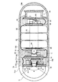
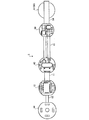
カプセル型内視鏡1は、図1に示すように、折り畳んだリジッドフレキ基板2と、この折り畳んだリジッドフレキ基板2を外装するカプセル70とを有している。図2及び図3に示すように、リジッドフレキ基板2は、剛性を有するリジッド基板10,30,40,50と屈曲可能な柔軟性を有するフレキシブル基板11,12,41,54とを一体に形成したものであり、フレキシブル基板11,12,41を互い違いに反対方向へ折り曲げることにより、リジッド基板10,30,40,50の積層が可能である。
As shown in FIG. 1, the capsule endoscope 1 includes a folded rigid-
リジッド基板は、被検体内の被検部位を撮像する機能を有するための撮像基板10と、被検部位を照明する機能を実行するための照明基板30と、各機能を実行させるための電力の供給を制御するためのスイッチ基板40と、各機能を実行させるための電力を供給するための電源基板50とである。そして、照明基板30と撮像基板10、撮像基板10とスイッチ基板40、スイッチ基板40と電源基板50とは並列して配置し、さらにそれぞれ可撓性材料からなるフレキシブル基板11,12,41により一直線上に接続してあらかじめ一体的に形成してある。また、電源基板50の右側縁部50Aからフレキシブル基板54が延在しており、このフレキシブル基板54には、送信ユニット60をなす送信基板61がスルーホールランドによって電気的に接続してある。
The rigid board includes an
図4に示すように、撮像基板10は略円盤形状を有し、撮像基板10の右側縁部10Aと左側縁部10Bとは、互いに平行な関係を有する直線によりそれぞれ切り欠いて2つの辺を形成してある。この右側縁部10Aと左側縁部10Bとからそれぞれフレキシブル基板11,12が延在している。このため、フレキシブル基板11,12の折り曲げに際して当該フレキシブル基板11,12の無理な変形を直線状の右側縁部10A及び左側縁部10Bによってそれぞれ抑制可能である。
As shown in FIG. 4, the
この右側縁部10A又は左側縁部10B、すなわち、フレキシブル基板11,12の延在方向(切り欠きによる2辺)は、撮像基板10に配設する電子部品の配設基準となり、図4に示すように、撮像基板10の前面には、フレキシブル基板11,12の延在方向と画素配列方向とが一致するようにイメージセンサ13があらかじめ配設してある。より詳細には、撮像基板10に被検体の被検部位を撮像するイメージセンサ13をボール・グリッド・アレイ(Ball Grid Array)により実装してある。イメージセンサ13は、その外形を多角形形状、例えば、CCD(Charge Coupled Diode)のような互いに平行な関係になる2辺を2組有する矩形の外周形状を備えた固体撮像素子13Aと、その上面に積層した矩形のカバーガラス13Bとにより矩形に構成してある。ここで、カバーガラス13Bは固体撮像素子13Aの上面を被覆している。なお、ここでは、画素の配列方向をイメージセンサ13の外周形状をなす2辺と平行な関係とするが、必ずしもこれに限られるものではない。
This
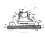
図5に示すように、イメージセンサ13の上面としてのカバーガラス13Bの上面には、レンズ支持部材14が取り付けてある。レンズ支持部材14は、カバーガラス13Bと密着して配置し、後述する照明手段から出射された照明光が被検部位で反射してなる反射光をイメージセンサ13に光学像として結像するレンズである小径レンズ15と大径レンズ16とを支持するものであり、ホルダ17とレンズ枠18とを有している。
As shown in FIG. 5, a
ホルダ17は、その一端側にはイメージセンサ13の上面(受光面)と固着する基部17Aを有し、全体として概略筒状形状を有する筒状部材にて構成し、基部17Aから他端側に、つまり紙面上方に延在する円筒部17Bとを有する筒状部材である。円筒部17Bに形成した穴部17Cは基部17Aを貫通し、ホルダ17の上方から入射した光をイメージセンサ13に導光可能である。基部17Aの下面、すなわち、イメージセンサ13の上面と当接する面の外形は、一辺をカバーガラス13Bの短辺と略同一の長さとする略正方形形状を有し、この下縁部の隣り合う二辺からそれぞれ下方にカバーガラス13Bの側面に当接する当接部17Dが延在して形成してある。
The
このホルダ17は、基部17Aの下面がカバーガラス13Bの上面と当接する一方、当接部17Dとカバーガラス13B上面の隣り合う二辺をなす側面とが当接することで、ホルダ17がカバーガラス13Bに対してあらかじめ高精度に位置決めして固着してある。
In the
また、当接部17Dとほぼ同一形状の補強部17Eがホルダ17の下縁部から延在して形成してあり、カバーガラス13Bとホルダ17とは、位置決め後に黒色の接着剤19によって固着してある。そして、カバーガラス13Bのホルダ17によって覆われていない露出面には、黒色の接着剤19が塗布してあり、露出面からの光の入射を防止でき、イメージセンサ13に鮮明な画像が投影可能である。なお、固体撮像素子13Aは、CCDに限定されるものではなく、例えばCMOS(Complementary Metal Oxide Semiconductor)などを用いることもできる。
Further, a reinforcing
ホルダ17には、レンズ枠18が取り付けてある。レンズ枠18は、小径レンズ15と大径レンズ16とを内部に支持するとともに、ホルダ17の円筒部17Bの内径以下の外径を有するものであり、円筒形状を有している。レンズ枠18の内周面には、先端部18Aと、小径部18Bと、大径部18Cとが形成してあり、各境界部分には段部18D,18Eが形成してある。
A
先端部18Aは、イメージセンサ13に像を結ぶ入射光を取り入れる部分であり、先端側を漏斗状に形成してある。小径部18Bには、前面が平面で後面が凸面の光の屈折率が大きい小径レンズ15がはめ込んであり、小径レンズ15の平面部分は先端部18Aの段部18Dと当接し、小径レンズ15の周面部分は小径部18Bに嵌合している。大径部18Cには、円筒形状のスペーサ20と、前面が凸面で後面が平面の光の屈折率が小さい大径レンズ16とがはめ込んであり、スペーサ20は、小径レンズ15と大径レンズ16とを所定の間隔で離隔させている。
The
また、レンズ枠18の外周面には、その軸方向の一端側には小径部18Fが、他端側、つまりイメージセンサ13側には大径部18Gが形成してあり、その境界部分には段部18Hが形成してある。大径部18Gはホルダ17の円筒部17Bの内周面に嵌合し、レンズ枠18はホルダ17に対して進退可能である。このため、レンズ枠18を進退させて、イメージセンサ13に像を投影する結像位置を調整可能であり、結像位置調整後にホルダ17とレンズ枠18とを接着剤21等によって固着してある。これにより、レンズ枠18は、その内部に支持したレンズとともに、イメージセンサ13に対して、ホルダ17を介してその光軸Oの方向に位置決めされ、固定されている。
Further, on the outer peripheral surface of the
また、図4に示すように、撮像基板10の前面にはイメージセンサ13を配設基準にして両隣に、イメージセンサ13を駆動する電源電圧回路用の電子部品として大型コンデンサ22が配設してある。この大型コンデンサ22は互いに平行な関係にある2辺を2組有する略矩形の外周形状となっているものである。すなわち、イメージセンサ13の2辺と大型コンデンサ22の2辺とが平行な関係になるように配設している。そして、イメージセンサ13、大型コンデンサ22を避けて、電子部品として所定の高さを有するイメージセンサ13を駆動するために必要なコンデンサ、抵抗等、各々所定の高さを有する他の電子部品23が整然と配設してある。
As shown in FIG. 4, a
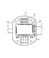
一方、図6に示すように、撮像基板10の後面の略中央には、右側縁部10A又は左側縁部10B、すなわち、フレキシブル基板11、12の延在方向を配設基準として、マイクロプロセッサ24(Digital Signal Processor)がフリップチップボンディングにより実装してあり、このマイクロプロセッサを基準にしてコンデンサ等の電子部品25が整然と配設してある。このため、電子部品25の集積が可能であり、カプセル型内視鏡1の小型化に寄与できる。なお、マイクロプロセッサ24は、カプセル型内視鏡1の駆動制御、イメージセンサ13の信号処理、及び照明基板30の駆動制御を行う。
On the other hand, as shown in FIG. 6, the
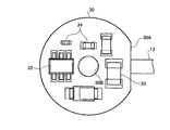
図7に示すように、照明基板30は略円盤形状を有し、照明基板30の右側縁部30Aは直線状に切り欠いて一辺を形成してある。この右側縁部30Aには、撮像基板10の左側縁部から延在したフレキシブル基板12が接続してある。このため、フレキシブル基板12の折り曲げに際して当該フレキシブル基板12の無理な変形を抑制可能である。
As shown in FIG. 7, the
照明基板30の中央部には、この照明基板を貫通した孔としての透孔30Bが形成してあり、透孔30Bと右側縁部30Aとは、照明基板30に配設する電子部品の配設基準となる。透孔30Bは、撮像基板10に照明基板30を所定の間隔を有して積層したときに、レンズ枠18の小径部18Fと嵌合するものであり、レンズ枠18の小径部18Fと略同一形状を有している。
A through
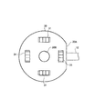
照明基板30の前面には、被検体内の被検部位を照明する照明光を出射するための照明手段として、照明基板30の前方の被写体に光を照射する発光ダイオード(Light Emitting Diode)等の発光素子からなる照明用電子部品の1つとしての照明部品31が配設してある。照明部品31は、非表示領域(後述する観察画面において非表示となる領域)と対応する位置に配設してある。
A light emitting diode (Light Emitting Diode) or the like that irradiates light on a subject in front of the
図8及び図9は、イメージセンサ13の受光面において後述する表示領域と各非表示領域に対して、照明部品31の配置位置を光軸Oの方向へ投影させることで、光軸方向から見た照明部品31とイメージセンサ13との配置位置の関係を同一平面上で表現したものであり、これらを用いてより詳しく説明をする。図8に示すように、イメージセンサ13が取得する画像Aは円形を有している。この円形の画像Aのうち、正方形の領域を観察画面において表示領域Bとすると、ハッチングを施したその余の領域は観察画面において非表示領域Cとなる。この非表示領域Cは観察画面に表示しないのであるから、鮮明な画像である必要はなく、この非表示領域Cに照明部品31による光の影響(図中二点鎖線で示す)を及ぼしても観察画面に表示することはない。したがって、この非表示領域Cと対応する位置、すなわち、照明部品31の光が表示領域Bの画像に影響を及ぼさない範囲で、表示領域Bに近づけた位置に照明部品31を配置してある。
FIGS. 8 and 9 show the position of the
また、図9に示すように、正方形の角部を切り落とした八角形の領域を観察画面において表示領域Dとすると、ハッチングを施したその余の領域は観察画面において非表示領域Eとなる。この場合にも非表示領域Eは観察画面に表示しないのであるから、鮮明な画像である必要はなく、この非表示領域Eに照明部品31による光の影響(図中二点鎖線で示す)を及ぼしても観察画面に表示することはない。したがって、この非表示領域と対応するする位置、すなわち、照明部品31の光が表示領域Dの画像に及ぼさない範囲で、表示領域に近づけた位置に照明部品31を配置してある。
As shown in FIG. 9, if an octagonal area obtained by cutting off the corners of a square is a display area D on the observation screen, the other hatched area becomes a non-display area E on the observation screen. Also in this case, since the non-display area E is not displayed on the observation screen, it is not necessary to be a clear image, and the influence of light by the illumination component 31 (indicated by a two-dot chain line in the figure) is not applied to the non-display area E. Even if applied, it is not displayed on the observation screen. Accordingly, the
つまり、図8及び図9のいずれの場合においても、イメージセンサ13は被検部位からの照明光の反射光を受光して被検部位の画像を生成するための有効領域(つまり、前述の観察画面上における各表示領域)と、この画像生成に寄与しない無効領域(つまり、前述の観察画面上における各非表示領域)とからなる受光面を有しており、この受光面における無効領域をイメージセンサ13の受光面と直交する方向である光軸Oに沿って照明基板30上に投影させて得られた照明基板30上の領域を部品配置部と規定し、この部品配置部に照明用電子部品の1例としての照明部品31を配置するようにしている。
That is, in either case of FIGS. 8 and 9, the
また、図1にも示したように、レンズ枠18に支持されたレンズ(小径レンズ15と大径レンズ16)によって所定の大きさの視野角αに基づく所定の視野範囲が形成されているので、さらにこの視野角αも考慮して照明用電子部品を配置する必要がある。つまり、照明用電子部品としての照明部品31を、その高さ方向の長さを鑑みてレンズが形成する視野範囲の外に位置するようにしている。なお、ここでいう照明用電子部品は照明部品31に限るものではなく、照明部品31を駆動させるための電子部品を含んでいても良い。
Further, as shown in FIG. 1, a predetermined viewing range based on a viewing angle α of a predetermined size is formed by the lenses (
このように照明部品31を配設すれば、表示領域B,Dと非表示領域C、Eとを問わずに取得画像に影響を及ぼさないように照明部品31を配設した場合(図8中二点差線で示す)と比較して、光軸Oと照明部品31の距離は短くできるので(L2に対してL1)、カプセル型内視鏡を径外方向において小型化できる。なお、照明部品31は発光ダイオードに限定されるものではなく、例えばEL(electroluminescence)などを用いることもできる。また、その数も4個に限られるものではない。
When the
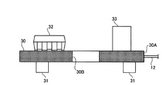
図10及び図11に示すように、照明基板30の後面には、照明部品31を駆動する駆動用の電子部品32と、照明部品31に安定した電圧を供給するための電子部品33と、小型コンデンサ等の電子部品34とが配設してある。
As shown in FIGS. 10 and 11, on the rear surface of the
図12に示すように、駆動用の電子部品32及び安定した電圧を供給するための電子部品33等の背の高い電子部品は、撮像基板10と照明基板30とを接続するフレキシブル基板12を折り曲げて、撮像基板10と照明基板30を所定の間隔を有して積層した場合に、撮像基板10の照明基板30と対向する面(撮像基板10の前面)に配設した背の低いコンデンサ又は抵抗等の電子部品23と対向する。
As shown in FIG. 12, tall electronic components such as the driving
一方、小型コンデンサ等の背の低い電子部品34は、撮像基板10と照明基板30とを接続するフレキシブル基板12を折り曲げて、撮像基板10と照明基板30とを対向して配設した場合に、撮像基板10の照明基板30と対向する面(撮像基板10の前面)に配設した背の高い大型コンデンサ22と対向する。
On the other hand, a short
すなわち、撮像基板10と照明基板30とを接続したフレキシブル基板12を折り曲げて、撮像基板10と照明基板30とを配設したリジッドフレキ基板2において、撮像基板10の前面に配設した背の高い大型コンデンサ22、背の低い小型コンデンサ、抵抗等の電子部品25と、互い違いに組み合う態様で、背の高い駆動用の電子部品32、安定した電圧を供給するための電子部品33、背の低い小型コンデンサ等の電子部品34を照明基板30の後面に配設してある。
That is, in the rigid
このため、撮像基板10と照明基板30との間隔を撮像基板10の前面に配設した背の高い電子部品と照明基板30の後面に配設した背の高い電子部品の高さとの和よりも狭くできる。なお、フレキシブル基板12は、イメージセンサ13とレンズ支持部材14の組み立て長よりも長く形成してある。
For this reason, the distance between the
このように構成した照明基板30は、撮像基板10と所定の間隔を有して対向配置した後に、絶縁性を有する接着剤35により、電気的に絶縁し固着してある。
The illuminating
スイッチ基板40は、図13及び図14に示すように、撮像基板10と同様に、略円盤形状を有し、スイッチ基板40の右側縁部40Aと左側縁部40Bとは、平行な2辺により切り欠いてある。そして、左側縁部40Bには、撮像基板10の右側縁部から延在したフレキシブル基板11が接続してあり、右側縁部40Aからフレキシブル基板41が延在している。このため、フレキシブル基板41の折り曲げに際して当該フレキシブル基板41の無理な変形を抑制可能である。
As shown in FIGS. 13 and 14, the
この右側縁部40Aと左側縁部40B、すなわちフレキシブル基板11,41の延在方向は、スイッチ基板40に配設する電子部品の配設基準となり、スイッチ基板40の中央部には、この2辺と平行に長円形の挿通穴部42が形成してある。
The
スイッチ基板40の前面には、リードスイッチ43が挿通穴部42に沈下するように配設してあり、撮像基板10の前面側への突出高さを抑えている。このリードスイッチ43は、ラッチ型のスイッチであり、初期状態でオフ、リードスイッチ43に近接した磁石(図示せず)を遠ざけることによりオフ状態からオン状態になるものである。また、リードスイッチ43を囲むように、メモリ44、振動子45、MIX46等の電子部品が整然と配設してある。
A
メモリ44には、マイクロプロセッサ24の初期値、固体撮像素子13Aの色のバラツキやホワイトバランス、及びカプセル型内視鏡1の固有番号などが記憶してあり、振動子45は、マイクロプロセッサ24に基本のクロックを与える。また、MIX46はフリップチップボンディングにより実装してあり、マイクロプロセッサ24から出力した映像信号とクロック信号の2つの信号を送信するに際し、1つの信号にミキシングする機能を有している。スイッチ基板40の後面には、電池のプラス極と当接する接点47が設けてある。なお、この接点47は、板バネで形成してある。
The
図15及び図16に示すように、電源基板50は略円盤形状を有し、電源基板50の右側縁部50Aと左側縁部50Bとは平行な2辺により切り欠いてある。そして、左側縁部50Bには、スイッチ基板40の右側縁部40Aから延在したフレキシブル基板41が接続してある。このため、フレキシブル基板の折り曲げに際して当該フレキシブル基板の変形を抑制可能である。電源基板50の前面には、図には明示しないが、電池のマイナス極と当接する接点が設けてあり、電源基板50の後面には、DCDCコンバータ51が設けてある。DCDCコンバータ51は、カプセル型内視鏡1に必要な一定の電圧を得るために電池52で得られる電圧をコントロールするものである。
As shown in FIGS. 15 and 16, the
図1に示すように、電源基板50とスイッチ基板40との間には、複数個(本実施の形態では3個)の電池52を挟み込んであり、輪切り状に形成した熱収縮チューブ53を収縮させて、スイッチ基板40と電源基板50との間に電池52を把持した状態で一体化してある。なお、フレキシブル基板41の中央部には、長円形状のスリット41Aが形成してあり、フレキシブル基板41は電池52の外周に沿って密着する。電池52は、外形が円盤形状であるボタン型の酸化銀電池などであり、複数個を直列にしてマイナス極側を電源基板50に向けて配置してある。なお、電池52は、酸化銀電池に限定されるものではなく、例えば充電式電池、発電式電池などを用いてもよい。
As shown in FIG. 1, a plurality of (three in the present embodiment)
また、電源基板50の右側縁部50Aには、フレキシブル基板54が延在してあり、このフレキシブル基板54には送信ユニット60が接続してある。この送信ユニット60はリジッドフレキ基板2と独立して作成し、その後、フレキシブル基板54とスルーホールランドにより接続したものである。
A
送信ユニット60は、図17及び18に示すように、送信基板61とアンテナ基板62とを有し、送信基板61は、略円盤形状を有している。送信基板61の右側縁部61Aは、1つの直線により切り欠いて一辺を形成してあり、この一辺は送信基板61に配設する電子部品の配設基準となり、送信基板61の後面には、この1辺を基準として電子部品が配設してある。アンテナ基板62は、送信基板61の後面から立設した端子63に取り付けてあり、アンテナ基板62の後面には略渦巻き状のアンテナパターン64が形成してある。送信ユニット60は、スイッチ基板40でミキシングした信号から一定の周波数、振幅、波形を持つ信号を取り出し、アンテナ基板62から外部に信号を送信可能である。
As shown in FIGS. 17 and 18, the
このように構成したスイッチ基板40と撮像基板10と、電源基板50と送信ユニット60とは、図1に示すように、所定の間隔を有して対向配置した後に、絶縁性を有する接着剤65により、電気的に絶縁し固着してある。
As shown in FIG. 1, the
積層したリジッドフレキ基板2は、カプセル型内視鏡1の内部構成を成し、この積層したリジッドフレキ基板2はカプセル70により外装してある。カプセル70は、先端カバー71とケース72とを有している。
The laminated rigid
先端カバー71は照明基板30の前面側を覆うものであり、略半球のドーム形状であって、後側を開口してある。この先端カバー71は、透明あるいは透光性を有し、照明部品31の照明光をカプセル70の外部に透過するとともに、当該照明光で照らした像をカプセル70の内部に透過する。
The front end cover 71 covers the front side of the
また、先端カバー71の開口部には、その開口の全周に渡って開口方向(後方)に延在した接続端部71Aが形成してある。接続端部71Aは、成型時の抜き勾配のない内外形に形成した円筒形状を有し、この接続端部71Aの外周面はケース72との接合面をなす。この接合面には、その全周に渡って無端状の突起71Bが設けてある。なお、突起71Bは、先端カバー71の接続端部71Aの端から離間して接合面の重合幅内の任意の位置、例えば重合幅方向において中央位置に設けてある。
In addition, the opening portion of the
また、図1に示すように先端カバー71において、接続端部71Aを延在する基端部分は、照明基板30の前面側を覆う略半球のドーム形状部分や、接続端部71Aに比較して断面を厚く形成した厚肉部71Cを有している。この厚肉部71Cは、先端カバー71の接続端部71Aの強度を確保し、例えば、落下時などの先端カバー71の割れを防止する。
Further, as shown in FIG. 1, in the
また、先端カバー71において、接続端部71Aを延在する基端部分の内周面には、当接部71Dが形成してある。当接部71Dに照明基板30を当接させることにより、先端カバー71と折り畳んだリジッドフレキ基板2とは、軸方向において所定の位置関係に位置決め可能である。
Further, in the
また、先端カバー71において、接続端部71Aを延在する基端部分の内径は、照明基板30及び撮像基板10の外径と略同一径を有している。このため、先端カバー71と折り畳んだリジッドフレキ基板2とは、径外方向において位置決め可能であり、先端カバー71の接続端部71Aの内周面と、照明基板30の外周面とが当接して、接続端部71Aがカプセル70の内方への変形を規制する。
Further, in the
そして、先端カバー71とケース72とを接続してカプセル70の内部に折り畳んだリジッドフレキ基板2を収容する場合には、先端カバー71における接続端部71Aの内周面と折り畳んだリジッドフレキ基板2との間に接着剤を注入して固着する。このように、先端カバー71に折り畳んだリジッドフレキ基板2を固着すると、リジッドフレキ基板2のうち、照明基板30が先端カバー71内に位置する。
When the
ケース72は、先端カバー71の後側において折り畳んだリジッドフレキ基板2を覆う部分である。ケース72は、円筒状の胴部72Aと、略半球のドーム形状とした後端部72Bとが一体に形成してあり、胴部72Aの前側が開口してある。また、ケース72の開口部72Cには、その開口の全周に渡って開口方向(前方)に延在した接続端部72Dが形成してある。接続端部72Dは、成型時の抜き勾配のない内外形に形成した円筒状を有し、この接続端部72Dの内周面は、先端カバー71との接合面をなす。この接合面には、その全周に渡って無端状の溝72Eが設けてある。また、溝72Eは、先端カバー71に設けた突起71Bの位置に応じて設けてある。重合幅は、略1〜5mmの範囲で3mmが好ましく、溝72Eを設ける位置は、重合幅の中央が好ましい。
The
このように設けた突起71Bと溝72Eとは、先端カバー71とケース72とが接合面において重合したときに互いに係合する。このように、突起71B及び溝72Eは、互いに係合によって先端カバー71とケース72との接続した状態を保持する。突起71Bを接合面の全周に渡って設け、溝72Eを接合面の全周に渡って設けてあるので、突起71Bと溝72Eとが係合し、先端カバー71とケース72とを接続した状態において、各接合面の相対的な摺動回転が可能である。
The protrusion 71B and the
そして、折り畳んだリジッドフレキ基板2の外周面に樹脂材料80を塗布し、先端カバー71の接続端部の接合面に接着剤を塗布した後、先端カバー71の接合端部の接合面と、ケース72の接合端部の接合面とを重合させて、先端カバー71とケース72とを接続する。このため、折り畳んだリジッドフレキ基板2の外周面とカプセルの内周面との間隙には樹脂材料が充填され、先端カバー71の接続端部の接合面とケース72の接続端部の接合面との間には接着剤が侵入する。その後、先端カバー71とケース72とを接続した状態において、先端カバー71とケース72とを相対的な摺動回転をさせ、接着剤を先端カバー71の接続端部の接合面とケース72の接続端部の接合面との間に行き渡らせる。この結果、先端カバー71とケース72との水密が確保され、カプセル70全体を水密に封止することができる。
And after apply | coating the
また、図に示すように先端カバー71とケース72とを接続した状態で、カプセルの外表面側にあらわれる相互の接続部分には、面取りが施してある。この面取りは、先端カバー71とケース72とを間でカプセルの外表面に生じ得る段を微少なものとするので、段が引っかかって先端カバー71とケース72とを引き離す外力を生じる事態を防止することができる。
Further, as shown in the figure, the connecting portions appearing on the outer surface side of the capsule in a state where the
なお、先端カバー71は、シクロオレフィンポリマー、ポリカーボネイト、アクリル、ポリサルフォンあるいはウレタンで形成してあり、特にシクロオレフィンポリマーあるいはポリカーボネイトが光学性能及び強度を確保するのに好ましく、ケース72は、シクロオレフィンポリマー、ポリカーボネイト、アクリル、ポリサルフォンあるいはウレタンで形成してあり、特にポリサルフォンが強度を確保するのに好ましい。
The
次に、上述したカプセル型内視鏡を用いた医療システムについて説明する。なお、図19はカプセル型内視鏡を用いた医療システムの概略図である。 Next, a medical system using the capsule endoscope described above will be described. FIG. 19 is a schematic view of a medical system using a capsule endoscope.
図19に示すように、カプセル型内視鏡を用いた医療システムは、パッケージ100に収納したカプセル型内視鏡1と、患者すなわち被検査者に着用させるジャケット102と、ジャケット102に着脱自在の受信機103と、コンピュータ104とにより構成してある。
As shown in FIG. 19, a medical system using a capsule endoscope includes a capsule endoscope 1 housed in a
ジャケット102には、カプセル型内視鏡1のアンテナ基板62から発信される電波を捕捉するアンテナ102a,102b,102c,102dが設けてあり、当該アンテナ102a,102b,102c,102dを介して、カプセル型内視鏡1と受信機103との間の通信が可能となっている。なお、アンテナ102a,102b,102c,102dの数は図17に示す4個に限定されず複数あればよい。複数のアンテナ102a,102b,102c,102dにより、カプセル型内視鏡1の移動に伴う位置に応じた電波を良好に受信することができる。また、各アンテナ102a,102b,102c,102dの受信強度により、カプセル型内視鏡1の体腔内における位置を検出することができる。
The
受信機103は、逐次受信される撮像画像データに対しホワイトバランス処理を行い、ホワイトバランス処理済の画像データを、例えばコンパクトフラッシュ(R)メモリカード(CFメモリカード)105に格納する。受信機に103よる受信は、カプセル型内視鏡1の撮像開始とは同期しておらず、受信機103の入力部の操作により受信開始と受信終了とを制御している。
The
コンピュータ104は、CFメモリカード105のリード/ライトなどを行う。このコンピュータ104は、医者もしくは看護士(検査者)がカプセル型内視鏡1によって撮像された被検体である患者体内の臓器などの画像を処理してコンピュータ104の観察画面(モニタ)に表示する。なお、観察画面は正方形又は正方形の角部を切り落とした八角形形状を有している。
The
上記システムの概略動作について説明する。まず、検査を開始する前に、パッケージ100からカプセル型内視鏡を取り出す。これにより、カプセル型内視鏡1のリードスイッチ43がオフ状態からオン状態に移行して、メイン電源をオンすることになる。次に、カプセル型内視鏡1を被検査者が口から飲み込む。これにより、カプセル型内視鏡1は、食道を通過し、消化管腔の蠕動運動により体腔内を進行し、逐次体腔内の像を撮像する。そして、カプセル型内視鏡1では、必要に応じてあるいは随時、撮像結果について撮像画像の電波が出力する。この電波は、ジャケット102のアンテナ102a,102b,102c,102dで捕捉される。捕捉された電波は、信号としてアンテナ102a,102b,102c,102dから受信機103へ中継される。次に、カプセル型内視鏡による被検査者の観察(検査)が終了すると、撮影画像データが格納されたCFメモリカード105を受信機103から取り出してコンピュータ104のメモリカード挿入孔に入れる。コンピュータ104では、CFメモリカード105に格納された撮影画像データが読み出され、その撮像画像データが患者別に対応して記憶される。そして、診断する場合にはその撮像した画像を処理して、コンピュータ104のモニタに表示する。
The general operation of the system will be described. First, before starting the inspection, the capsule endoscope is taken out from the
上述した実施の形態に係るカプセル型内視鏡1は、照明基板30、撮像基板10、スイッチ基板40、電源基板50の順にフレキシブル基板11、12,41により一直線上に接続してあるが、フレキシブル基板11,12,41を折り曲げたときに、照明基板30、撮像基板10、スイッチ基板40、電源基板50の順に位置するものであれば良く、例えば同一平面上であれば必ずしも一直線上に接続するものでなくても良い。
In the capsule endoscope 1 according to the above-described embodiment, the
上述した実施の形態に係るカプセル型内視鏡1によれば、被検体の被検部位に照明光を照射するのに必要な照明用電子部品を実装するために準備された照明基板30と、被検部位からの照明光の反射光を受光して被検部位の画像を生成するための有効領域(表示領域B、D)とこの画像生成に寄与しない無効領域(非表示領域C,E)とからなる受光面を有するイメージセンサ13と、照明基板30に並列して配置させられたイメージセンサ13を実装した撮像基板10と、イメージセンサ13の受光面における無効領域(非表示領域C,E)をイメージセンサ13の受光面と直交する方向へ投影させて得られた照明基板30上の領域に設けられた照明用電子部品を配置する部品配置部とを備えたので、従来から求められる基本的な性能を維持しつつも、従来のものよりもさらに小型化し、被験者が容易に嚥下することができる。
According to the capsule endoscope 1 according to the above-described embodiment, the
1 カプセル型内視鏡
2 リジッドフレキ基板
10 撮像基板(リジッド基板)
11 フレキシブル基板
12 フレキシブル基板
13 イメージセンサ
15 小径レンズ
16 大径レンズ
17 ホルダ
18 レンズ枠
30 照明基板(リジッド基板)
31 照明部品
40 スイッチ基板(リジッド基板)
41 フレキシブル基板
50 電源基板(リジッド基板)
54 フレキシブル基板
60 送信ユニット
70 カプセル
71 先端カバー
72 ケース
103 受信機
104 コンピュータ
105 メモリカード
1
DESCRIPTION OF
31
41
54
Claims (3)
前記被検部位からの前記照明光の反射光を受光して前記被検部位の画像を生成するための有効領域とこの画像生成に寄与しない無効領域とからなる受光面を有するイメージセンサと、
前記照明基板に並列して配置させられた前記イメージセンサを実装した撮像基板と、
前記イメージセンサの受光面における前記無効領域を前記イメージセンサの受光面と直交する方向へ投影させて得られた前記照明基板の前記照明基板上の領域に設けられた前記照明用電子部品を配置する部品配置部と
を備えたことを特徴とするカプセル型内視鏡。 An illumination board prepared for mounting the illumination electronic components necessary for irradiating illumination light to the test site of the subject;
An image sensor having a light receiving surface including an effective area for receiving reflected light of the illumination light from the test site and generating an image of the test site and an ineffective area that does not contribute to image generation;
An imaging board mounted with the image sensor arranged in parallel with the illumination board;
The illumination electronic component provided in a region on the illumination board of the illumination board obtained by projecting the invalid area on the light reception face of the image sensor in a direction orthogonal to the light reception face of the image sensor is disposed. A capsule endoscope comprising: a component placement unit.
前記照明用電子部品は、前記レンズが形成する視野範囲の外に配置されるように前記部品配置部に配置されたことを特徴とする請求項1に記載のカプセル型内視鏡。 A lens that forms a viewing range based on a viewing angle of a predetermined size, and that forms reflected light of the illumination light from the test site on the light receiving surface of the image sensor as an optical image of the test site Have
The capsule endoscope according to claim 1, wherein the illumination electronic component is arranged in the component arrangement unit so as to be arranged outside a visual field range formed by the lens.
Priority Applications (5)
| Application Number | Priority Date | Filing Date | Title |
|---|---|---|---|
| JP2004017137A JP2005205077A (en) | 2004-01-26 | 2004-01-26 | Capsule type endoscope |
| PCT/JP2005/000869 WO2005070280A1 (en) | 2004-01-26 | 2005-01-24 | Capsule-type endoscope |
| AU2005206035A AU2005206035B2 (en) | 2004-01-26 | 2005-01-24 | Capsule-type endoscope |
| EP05704050A EP1709899B1 (en) | 2004-01-26 | 2005-01-24 | Capsule-type endoscope |
| US11/492,603 US8348835B2 (en) | 2004-01-26 | 2006-07-25 | Capsule type endoscope |
Applications Claiming Priority (1)
| Application Number | Priority Date | Filing Date | Title |
|---|---|---|---|
| JP2004017137A JP2005205077A (en) | 2004-01-26 | 2004-01-26 | Capsule type endoscope |
Publications (2)
| Publication Number | Publication Date |
|---|---|
| JP2005205077A true JP2005205077A (en) | 2005-08-04 |
| JP2005205077A5 JP2005205077A5 (en) | 2007-04-19 |
Family
ID=34805519
Family Applications (1)
| Application Number | Title | Priority Date | Filing Date |
|---|---|---|---|
| JP2004017137A Pending JP2005205077A (en) | 2004-01-26 | 2004-01-26 | Capsule type endoscope |
Country Status (5)
| Country | Link |
|---|---|
| US (1) | US8348835B2 (en) |
| EP (1) | EP1709899B1 (en) |
| JP (1) | JP2005205077A (en) |
| AU (1) | AU2005206035B2 (en) |
| WO (1) | WO2005070280A1 (en) |
Cited By (3)
| Publication number | Priority date | Publication date | Assignee | Title |
|---|---|---|---|---|
| JP2007289528A (en) * | 2006-04-26 | 2007-11-08 | Olympus Medical Systems Corp | Antenna unit and receiver |
| JP2010045445A (en) * | 2008-08-08 | 2010-02-25 | Sharp Corp | Solid state imaging apparatus and electronic apparatus including the same |
| JP2010045447A (en) * | 2008-08-08 | 2010-02-25 | Sharp Corp | Solid state imaging apparatus and electronic apparatus including the same |
Families Citing this family (45)
| Publication number | Priority date | Publication date | Assignee | Title |
|---|---|---|---|---|
| US20060169294A1 (en) * | 2004-12-15 | 2006-08-03 | Kaler Karan V | Inertial navigation method and apparatus for wireless bolus transit monitoring in gastrointestinal tract |
| US8235055B2 (en) | 2005-01-11 | 2012-08-07 | Uti Limited Partnership | Magnetic levitation of intraluminal microelectronic capsule |
| US8852083B2 (en) * | 2005-02-04 | 2014-10-07 | Uti Limited Partnership | Self-stabilized encapsulated imaging system |
| US20060231110A1 (en) * | 2005-03-24 | 2006-10-19 | Mintchev Martin P | Ingestible capsule for esophageal monitoring |
| CN102008281B (en) * | 2006-04-25 | 2013-05-22 | 奥林巴斯医疗株式会社 | Encapsulated endoscope |
| JP4682158B2 (en) * | 2007-01-16 | 2011-05-11 | オリンパスメディカルシステムズ株式会社 | Imaging device |
| JP2009082503A (en) | 2007-09-28 | 2009-04-23 | Fujifilm Corp | Imaging device and endoscope equipped with the same |
| US9872609B2 (en) | 2009-06-18 | 2018-01-23 | Endochoice Innovation Center Ltd. | Multi-camera endoscope |
| US8926502B2 (en) | 2011-03-07 | 2015-01-06 | Endochoice, Inc. | Multi camera endoscope having a side service channel |
| US9901244B2 (en) | 2009-06-18 | 2018-02-27 | Endochoice, Inc. | Circuit board assembly of a multiple viewing elements endoscope |
| US11278190B2 (en) | 2009-06-18 | 2022-03-22 | Endochoice, Inc. | Multi-viewing element endoscope |
| US9101268B2 (en) | 2009-06-18 | 2015-08-11 | Endochoice Innovation Center Ltd. | Multi-camera endoscope |
| US9706903B2 (en) | 2009-06-18 | 2017-07-18 | Endochoice, Inc. | Multiple viewing elements endoscope system with modular imaging units |
| US9402533B2 (en) | 2011-03-07 | 2016-08-02 | Endochoice Innovation Center Ltd. | Endoscope circuit board assembly |
| US10165929B2 (en) | 2009-06-18 | 2019-01-01 | Endochoice, Inc. | Compact multi-viewing element endoscope system |
| US9101287B2 (en) | 2011-03-07 | 2015-08-11 | Endochoice Innovation Center Ltd. | Multi camera endoscope assembly having multiple working channels |
| CA2765559C (en) | 2009-06-18 | 2017-09-05 | Peer Medical Ltd. | Multi-camera endoscope |
| US11864734B2 (en) | 2009-06-18 | 2024-01-09 | Endochoice, Inc. | Multi-camera endoscope |
| US9492063B2 (en) | 2009-06-18 | 2016-11-15 | Endochoice Innovation Center Ltd. | Multi-viewing element endoscope |
| US11547275B2 (en) | 2009-06-18 | 2023-01-10 | Endochoice, Inc. | Compact multi-viewing element endoscope system |
| US9642513B2 (en) | 2009-06-18 | 2017-05-09 | Endochoice Inc. | Compact multi-viewing element endoscope system |
| US9713417B2 (en) | 2009-06-18 | 2017-07-25 | Endochoice, Inc. | Image capture assembly for use in a multi-viewing elements endoscope |
| WO2012077117A1 (en) | 2010-12-09 | 2012-06-14 | Peermedical Ltd. | Flexible electronic circuit board multi-camera endoscope |
| EP2312919B1 (en) * | 2009-10-08 | 2013-03-13 | Sick Ag | Optoelectronic sensor |
| CA2941578A1 (en) | 2010-09-08 | 2012-03-15 | Covidien Lp | Catheter with imaging assembly |
| US9560953B2 (en) | 2010-09-20 | 2017-02-07 | Endochoice, Inc. | Operational interface in a multi-viewing element endoscope |
| US10080486B2 (en) | 2010-09-20 | 2018-09-25 | Endochoice Innovation Center Ltd. | Multi-camera endoscope having fluid channels |
| CN103403605A (en) | 2010-10-28 | 2013-11-20 | 恩多巧爱思创新中心有限公司 | Optical systems for multi-sensor endoscopes |
| US11889986B2 (en) | 2010-12-09 | 2024-02-06 | Endochoice, Inc. | Flexible electronic circuit board for a multi-camera endoscope |
| JP6054874B2 (en) | 2010-12-09 | 2016-12-27 | エンドチョイス イノベーション センター リミテッド | Flexible electronic circuit board for multi-camera endoscope |
| EP3228236A1 (en) | 2011-02-07 | 2017-10-11 | Endochoice Innovation Center Ltd. | Multi-element cover for a multi-camera endoscope |
| JP5806557B2 (en) * | 2011-08-31 | 2015-11-10 | オリンパス株式会社 | Capsule endoscope |
| JP5913870B2 (en) * | 2011-08-31 | 2016-04-27 | オリンパス株式会社 | Capsule medical device |
| EP2604175B1 (en) | 2011-12-13 | 2019-11-20 | EndoChoice Innovation Center Ltd. | Removable tip endoscope |
| CA2798729A1 (en) | 2011-12-13 | 2013-06-13 | Peermedical Ltd. | Rotatable connector for an endoscope |
| US9560954B2 (en) | 2012-07-24 | 2017-02-07 | Endochoice, Inc. | Connector for use with endoscope |
| US10045713B2 (en) | 2012-08-16 | 2018-08-14 | Rock West Medical Devices, Llc | System and methods for triggering a radiofrequency transceiver in the human body |
| US9517184B2 (en) | 2012-09-07 | 2016-12-13 | Covidien Lp | Feeding tube with insufflation device and related methods therefor |
| US9198835B2 (en) | 2012-09-07 | 2015-12-01 | Covidien Lp | Catheter with imaging assembly with placement aid and related methods therefor |
| USD735343S1 (en) | 2012-09-07 | 2015-07-28 | Covidien Lp | Console |
| US9986899B2 (en) | 2013-03-28 | 2018-06-05 | Endochoice, Inc. | Manifold for a multiple viewing elements endoscope |
| US9993142B2 (en) | 2013-03-28 | 2018-06-12 | Endochoice, Inc. | Fluid distribution device for a multiple viewing elements endoscope |
| US10499794B2 (en) | 2013-05-09 | 2019-12-10 | Endochoice, Inc. | Operational interface in a multi-viewing element endoscope |
| JP6767261B2 (en) | 2013-10-22 | 2020-10-14 | ロック ウエスト メディカル デバイス, エルエルシー | A system for locating a swallowable tablet sensor with three transmitting elements |
| CN111512493B (en) * | 2018-03-07 | 2022-01-25 | 普和希控股公司 | Communication device |
Citations (1)
| Publication number | Priority date | Publication date | Assignee | Title |
|---|---|---|---|---|
| JP2003325441A (en) * | 2002-03-08 | 2003-11-18 | Olympus Optical Co Ltd | Capsule endoscope |
Family Cites Families (14)
| Publication number | Priority date | Publication date | Assignee | Title |
|---|---|---|---|---|
| IL130486A (en) * | 1999-06-15 | 2005-08-31 | Given Imaging Ltd | Optical system |
| JP2001091860A (en) | 1999-09-22 | 2001-04-06 | Asahi Optical Co Ltd | Capsule endoscope |
| WO2002054932A2 (en) * | 2001-01-16 | 2002-07-18 | Given Imaging Ltd. | System and method for wide field imaging of body lumens |
| WO2002102224A2 (en) * | 2001-06-18 | 2002-12-27 | Given Imaging Ltd. | In vivo sensing device with a circuit board having rigid sections and flexible sections |
| US20030117491A1 (en) * | 2001-07-26 | 2003-06-26 | Dov Avni | Apparatus and method for controlling illumination in an in-vivo imaging device |
| IL151049A0 (en) * | 2001-08-02 | 2003-04-10 | Given Imaging Ltd | In vivo imaging methods and devices |
| US20030158503A1 (en) * | 2002-01-18 | 2003-08-21 | Shinya Matsumoto | Capsule endoscope and observation system that uses it |
| JP4009473B2 (en) * | 2002-03-08 | 2007-11-14 | オリンパス株式会社 | Capsule endoscope |
| JP3895618B2 (en) * | 2002-03-08 | 2007-03-22 | オリンパス株式会社 | Capsule endoscope |
| JP2003260025A (en) * | 2002-03-08 | 2003-09-16 | Olympus Optical Co Ltd | Capsule endoscope |
| US7662094B2 (en) * | 2002-05-14 | 2010-02-16 | Given Imaging Ltd. | Optical head assembly with dome, and device for use thereof |
| US7473218B2 (en) * | 2002-08-06 | 2009-01-06 | Olympus Corporation | Assembling method of capsule medical apparatus |
| US7118529B2 (en) * | 2002-11-29 | 2006-10-10 | Given Imaging, Ltd. | Method and apparatus for transmitting non-image information via an image sensor in an in vivo imaging system |
| TW589170B (en) * | 2002-12-25 | 2004-06-01 | De-Yang Tian | Endoscopic device |
-
2004
- 2004-01-26 JP JP2004017137A patent/JP2005205077A/en active Pending
-
2005
- 2005-01-24 WO PCT/JP2005/000869 patent/WO2005070280A1/en active Application Filing
- 2005-01-24 AU AU2005206035A patent/AU2005206035B2/en not_active Ceased
- 2005-01-24 EP EP05704050A patent/EP1709899B1/en not_active Expired - Fee Related
-
2006
- 2006-07-25 US US11/492,603 patent/US8348835B2/en active Active
Patent Citations (1)
| Publication number | Priority date | Publication date | Assignee | Title |
|---|---|---|---|---|
| JP2003325441A (en) * | 2002-03-08 | 2003-11-18 | Olympus Optical Co Ltd | Capsule endoscope |
Cited By (3)
| Publication number | Priority date | Publication date | Assignee | Title |
|---|---|---|---|---|
| JP2007289528A (en) * | 2006-04-26 | 2007-11-08 | Olympus Medical Systems Corp | Antenna unit and receiver |
| JP2010045445A (en) * | 2008-08-08 | 2010-02-25 | Sharp Corp | Solid state imaging apparatus and electronic apparatus including the same |
| JP2010045447A (en) * | 2008-08-08 | 2010-02-25 | Sharp Corp | Solid state imaging apparatus and electronic apparatus including the same |
Also Published As
| Publication number | Publication date |
|---|---|
| AU2005206035A1 (en) | 2005-08-04 |
| EP1709899A4 (en) | 2007-07-18 |
| US8348835B2 (en) | 2013-01-08 |
| EP1709899B1 (en) | 2013-03-06 |
| EP1709899A1 (en) | 2006-10-11 |
| US20060264083A1 (en) | 2006-11-23 |
| WO2005070280A1 (en) | 2005-08-04 |
| AU2005206035A2 (en) | 2005-08-04 |
| AU2005206035B2 (en) | 2009-07-02 |
Similar Documents
| Publication | Publication Date | Title |
|---|---|---|
| JP2005205077A (en) | Capsule type endoscope | |
| JP4598498B2 (en) | Intra-subject introduction device | |
| US8152713B2 (en) | Capsule endoscope with illumination board section and method of assembling | |
| JP4515747B2 (en) | Capsule medical device | |
| EP3195787A1 (en) | Capsule-type medical device | |
| JP3981359B2 (en) | Capsule endoscope | |
| JP4024763B2 (en) | Endoscopic imaging apparatus and method for assembling endoscopic imaging apparatus | |
| JP4516139B2 (en) | Capsule medical device | |
| JP4533635B2 (en) | Method for manufacturing capsule medical device | |
| JP4515100B2 (en) | Endoscopic imaging device | |
| JP4373180B2 (en) | Capsule endoscope and imaging device | |
| JP2005198965A (en) | Capsule type medical device | |
| JP2005204924A (en) | Capsule type endoscope | |
| JP2005124961A (en) | Capsule type medical device | |
| JP4727214B2 (en) | Intra-subject introduction device | |
| JP4429745B2 (en) | Capsule medical device | |
| JP4583768B2 (en) | Capsule medical device | |
| JP2006149462A (en) | Device for acquiring information inside subject | |
| JP2005204925A (en) | Capsule type medical device | |
| JP2006149461A (en) | Device for acquiring information inside subject |
Legal Events
| Date | Code | Title | Description |
|---|---|---|---|
| A621 | Written request for application examination |
Free format text: JAPANESE INTERMEDIATE CODE: A621 Effective date: 20070125 |
|
| A521 | Written amendment |
Free format text: JAPANESE INTERMEDIATE CODE: A523 Effective date: 20070302 |
|
| A131 | Notification of reasons for refusal |
Free format text: JAPANESE INTERMEDIATE CODE: A131 Effective date: 20090811 |
|
| A521 | Written amendment |
Free format text: JAPANESE INTERMEDIATE CODE: A523 Effective date: 20091002 |
|
| A02 | Decision of refusal |
Free format text: JAPANESE INTERMEDIATE CODE: A02 Effective date: 20091222 |
|
| A521 | Written amendment |
Free format text: JAPANESE INTERMEDIATE CODE: A523 Effective date: 20100323 |
|
| A911 | Transfer to examiner for re-examination before appeal (zenchi) |
Free format text: JAPANESE INTERMEDIATE CODE: A911 Effective date: 20100326 |
|
| A912 | Re-examination (zenchi) completed and case transferred to appeal board |
Free format text: JAPANESE INTERMEDIATE CODE: A912 Effective date: 20100416 |