JP2004362144A - Method for managing operation, execution device, and processing program - Google Patents
Method for managing operation, execution device, and processing program Download PDFInfo
- Publication number
- JP2004362144A JP2004362144A JP2003158263A JP2003158263A JP2004362144A JP 2004362144 A JP2004362144 A JP 2004362144A JP 2003158263 A JP2003158263 A JP 2003158263A JP 2003158263 A JP2003158263 A JP 2003158263A JP 2004362144 A JP2004362144 A JP 2004362144A
- Authority
- JP
- Japan
- Prior art keywords
- policy
- information
- monitoring
- user
- business
- Prior art date
- Legal status (The legal status is an assumption and is not a legal conclusion. Google has not performed a legal analysis and makes no representation as to the accuracy of the status listed.)
- Pending
Links
Images


Classifications
-
- G—PHYSICS
- G06—COMPUTING; CALCULATING OR COUNTING
- G06Q—INFORMATION AND COMMUNICATION TECHNOLOGY [ICT] SPECIALLY ADAPTED FOR ADMINISTRATIVE, COMMERCIAL, FINANCIAL, MANAGERIAL OR SUPERVISORY PURPOSES; SYSTEMS OR METHODS SPECIALLY ADAPTED FOR ADMINISTRATIVE, COMMERCIAL, FINANCIAL, MANAGERIAL OR SUPERVISORY PURPOSES, NOT OTHERWISE PROVIDED FOR
- G06Q99/00—Subject matter not provided for in other groups of this subclass
-
- G—PHYSICS
- G06—COMPUTING; CALCULATING OR COUNTING
- G06F—ELECTRIC DIGITAL DATA PROCESSING
- G06F11/00—Error detection; Error correction; Monitoring
- G06F11/30—Monitoring
- G06F11/34—Recording or statistical evaluation of computer activity, e.g. of down time, of input/output operation ; Recording or statistical evaluation of user activity, e.g. usability assessment
- G06F11/3409—Recording or statistical evaluation of computer activity, e.g. of down time, of input/output operation ; Recording or statistical evaluation of user activity, e.g. usability assessment for performance assessment
Landscapes
- Business, Economics & Management (AREA)
- Physics & Mathematics (AREA)
- General Business, Economics & Management (AREA)
- General Physics & Mathematics (AREA)
- Engineering & Computer Science (AREA)
- Theoretical Computer Science (AREA)
- Debugging And Monitoring (AREA)
- Storage Device Security (AREA)
Abstract
Description
【0001】
【発明の属する技術分野】
本発明はプログラムやリソースの状態を監視してコンピュータシステムの運用を管理する運用管理装置に関し、特に業務処理を行うプログラムやリソースを監視する為の監視ツリー等の監視構造を生成してコンピュータシステムの運用管理を行う運用管理に適用して有効な技術に関するものである。
【0002】
【従来の技術】
コンピュータシステムの運用を管理する統合システム運用管理では、システム上の障害による影響範囲を把握する為、システム内に存在する各種リソース(サーバ、アプリケーション、データベース、ネットワーク機器、ストレージ機器等)を業務・組織・アプリケーション等、ビジネスの観点でグループ化、階層化してシステムを管理/監視する手法が求められてきている。この場合、事前に業務等の意味のある単位にリソースをグループ化する「業務構成定義作業」が必要であり、従来、以下の様な方法が用いられている。
【0003】
すなわち、システム上に存在するリソースをアイコンとして表示しておき、ある業務を構成しているリソースアイコンをユーザが手動でグループ化する方法や、業務を構成するリソースを特定する為の属性ルールをユーザが手動で定義し、そのルールに基づいて業務を構成するリソースを自動的に抽出することで業務構成を定義する方法である。
【0004】
また、監視ツリー等の監視構造は予め与えられた構造のみが用いられるのが一般的であり、監視構造そのものをユーザ毎に自由に変更することは容易には出来ない。例えば、特許文献1の発明においては、ソフトウェアモジュール間の相関関係をアイコンで表示し、障害時の影響の伝播や障害による状態変化の表示を行う方法についての提案が行われているが、各モジュール間の関係(階層構造)は、所定の構造として与えられたものが用いられている。
【0005】
【特許文献1】
特開2000−181756号公報
【0006】
【発明が解決しようとする課題】
前記従来技術の業務構成定義作業では、リソースアイコンのグループ化や、業務を構成するリソースを特定する為の属性ルールの定義をユーザが手動で行わなければならず、またそれを業務の数だけ繰り返し実行する必要がある為、システム規模が大きくなればなる程、ユーザによる業務構成定義作業が複雑で負荷が高くなるという問題がある。
また前記従来技術では、プログラムやリソースを監視する為の監視構造を作成する際に、ユーザのニーズに合わせて異なる監視構造を作成することについて考慮されていないという問題がある。
【0007】
本発明の目的は、上記問題を解決し、プログラムと特定のリソースとを関係付けた監視構造や特定のリソースと他のリソースとを関係付けた監視構造等の各種構造を示す監視構造情報を効率的に生成することが可能な技術を提供することにある。また本発明の他の目的は、ユーザ毎の監視対象範囲や権限を考慮して、ユーザに適した監視構造を提供すること、不要な情報へのアクセスを防止すること、ユーザの設定作業負担を軽減すること、ネットワーク負荷を軽減すると共に情報読み込みを高速化すること、各コンピュータ上の業務情報の変更に応じて監視構造の変更を行うこと、不要な業務情報の参照を省略して相関関係情報の生成を効率化することのいずれかを可能とする技術を提供することにある。
【0008】
【課題を解決するための手段】
本発明は、プログラムやリソースの状態を監視してコンピュータシステムの運用を管理する運用管理において、各コンピュータで用いられているプログラムやリソースを示す業務情報から当該プログラムやリソースを監視する為の監視構造情報を生成するものである。
【0009】
本発明の運用管理では、各ユーザの監視ニーズや嗜好を把握する為、「ポリシー」のメニューを表示し、ユーザによって選択された情報をDB(Database)で管理する。
【0010】
ここでポリシーとは、監視構造を生成する際の基準を示すものであり、業務(例えばジョブグループや業務アプリケーション)、ドメイン、組織・業務分掌、地域・位置情報等で監視対象であるリソースをグループ化する為のグループ化ポリシー、ユーザの分掌等による監視対象項目(業務やリソース等)を選択する為の監視項目ポリシー、何を中心にシステムを監視したいか(例えば業務中心、サーバ中心)によって監視の階層構造を変更する監視視点ポリシー、クラスタ対応(複数サーバの仮想化)、SAN(Storage Area Network)対応(複数ストレージの仮想化)、VLAN(Virtual LAN)対応(ネットワークの仮想化)等の仮想化の内容を監視構造に取り入れる仮想化ポリシー等がある。
【0011】
次に、前記設定されたポリシーに従って、各コンピュータで用いられている他の管理製品群(ジョブ管理、ネットワーク管理、アプリケーション管理等)の管理データや、クラスタ製品の設定情報等、業務構成情報を含む既存の業務情報を収集し、各コンピュータのプログラムやリソースの相関関係を示す相関関係情報を生成して管理する。
【0012】
そして、前記生成した相関関係情報をユーザのポリシーに応じた監視の基本構造に従ってマージして、前記プログラムやリソースを監視する為の構造を示す監視構造情報を生成することにより、ユーザのニーズに合った監視構造(例えば監視ツリー)の生成を行う。これらの処理により、ユーザの見たい視点や監視したい項目等に応じた監視構造を各コンピュータの業務情報により自動生成することができる。
【0013】
また、前記ポリシーを選択する為のメニューの内容を業種や権限等に応じてユーザ毎に変更するものとしたり、予め設定された内容により前記ポリシーの一部または全部の設定を強制的に行うものとしても良い。これにより、明らかにユーザが選択しない項目やユーザに選択させたくない項目を非表示としたり、ユーザの設定作業負担を軽減することができる。
【0014】
以上の様に本発明の運用管理によれば、各コンピュータで用いられているプログラムやリソースを示す業務情報から当該プログラムやリソースを監視する為の監視構造情報を生成するので、プログラムと特定のリソースとを関係付けた監視構造や特定のリソースと他のリソースとを関係付けた監視構造等の各種構造を示す監視構造情報を効率的に生成することが可能である。
【0015】
【発明の実施の形態】
(実施形態1)
以下にユーザ毎に選択されたポリシーに基づき、必要な情報をシステム上の各業務コンピュータから収集し、ユーザのニーズに合った監視構造を生成する実施形態1の運用管理装置について説明する。
【0016】
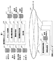
図1は本実施形態の運用管理システムの全体構成を示す図である。図1に示す様に本実施形態の運用管理コンピュータ100は、ポリシー取得部101と、基本構造管理部102と、関係管理部103と、監視構造生成部104と、表示部105とを有している。
【0017】
ポリシー取得部101は、ユーザによって選択されたポリシーを取得する処理部である。基本構造管理部102は、ポリシー取得部101によって取得したポリシーに基づいて、プログラムやリソースを監視する為の監視構造の基本構造を設定して管理する処理部である。
【0018】
関係管理部103は、各業務コンピュータで用いられているプログラムやリソースを示す業務情報を参照し、それらの相関関係を示す相関関係情報を生成して管理する処理部である。監視構造生成部104は、前記プログラムやリソースを監視する為の構造を示す監視構造情報を前記生成した相関関係情報に従って生成する処理部である。表示部105は、前記生成した監視構造情報に基づいて監視構造を表示する処理部である。なお、ポリシー取得部101、基本構造管理部102、関係管理部103、監視構造生成部104、表示部105は必ずしも1つの運用管理コンピュータ100上に存在する必要はなく、複数の運用管理コンピュータ100上に分割して配備しても良い。
【0019】
運用管理コンピュータ100をポリシー取得部101、基本構造管理部102、関係管理部103、監視構造生成部104及び表示部105として機能させる為のプログラムは、CD−ROM等の記録媒体に記録され磁気ディスク等に格納された後、メモリにロードされて実行されるものとする。なお前記プログラムを記録する記録媒体はCD−ROM以外の他の記録媒体でも良い。また前記プログラムを当該記録媒体から情報処理装置にインストールして使用しても良いし、ネットワークを通じて当該記録媒体にアクセスして前記プログラムを使用するものとしても良い。
【0020】
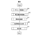
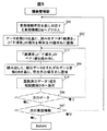
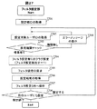
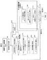
図2は本実施形態の全体の処理手順を示すフローチャートである。ステップ201で運用管理コンピュータ100のポリシー取得部101は、ポリシーを設定する為のメニューを表示してユーザからの入力を受け付けることにより、ユーザによって設定されたポリシーを取得する処理を行う。
【0021】
本実施形態におけるポリシーは、プログラムやリソースを監視する為の監視構造を生成する際の基準を示すものであり、前述したグループ化ポリシー、監視項目ポリシー、監視視点ポリシー、仮想化ポリシーがあるものとするが、他のポリシーを追加しても良い。
【0022】
ステップ202で基本構造管理部102は、ポリシー取得部101によって取得したポリシーに基づいて、プログラムやリソースを監視する為の監視構造の基本的な構造を示す基本構造を設定して管理する処理を行う。
【0023】
ステップ203で関係管理部103は、前記取得したポリシーに従って、各業務コンピュータで用いられている他の管理製品群(ジョブ管理、ネットワーク管理、アプリケーション管理等)等から業務構成に関わる必要な業務情報(ジョブグループ構成情報等)を収集し、各業務コンピュータのプログラムやリソースの相関関係を示す相関関係情報を生成して管理する処理を行う。
【0024】
ステップ204で監視構造生成部104は、前記生成した相関関係情報を前記基本構造に従ってマージして、前記プログラムやリソースを監視する為の構造を示す監視構造情報を生成することにより、ユーザのニーズに合った監視構造(例えば監視ツリー)の生成を行う。これらの処理により、ユーザの見たい視点や監視したい項目等に応じた監視構造を各コンピュータの業務情報により自動生成することができる。
ステップ205で表示部105は、前記生成した監視構造の情報に基づいて監視ツリー等の監視構造を表示する処理を行う。
【0025】
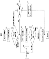
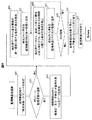
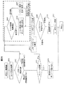
図3は本実施形態のポリシー取得部101の処理手順を示すフローチャートである。ステップ301でポリシー取得部101は、ポリシーの取得が行われるユーザを識別する為のユーザIDを取得する。
【0026】
ステップ302では、ユーザポリシーDB112を参照して前記取得したユーザIDに対応する登録識別子を読み出し、その登録識別子に「1」が設定されているかどうかを判定することによりユーザポリシーの登録有無を調べ、未設定である場合にはステップ303へ進み、設定済みである場合にはステップ309へ進む。なお、登録識別子は当該ユーザがポリシーを設定済みかどうかを識別する為の識別子であり、本実施形態では、未実施ならば「0」、登録済みであれば「1」と設定しておくことで登録の有無を識別する方法を採っているが、他の識別方法で識別しても良い。
【0027】
ステップ303では、ポリシー項目DB111からポリシー項目を読み出してポリシーを設定する為のメニューを表示し、ステップ304では、前記メニューからのユーザの設定内容の入力を受け付けることにより、ユーザポリシーを取得する。
【0028】
ステップ305では、前記取得したユーザポリシーの内容をチェックして矛盾があるかどうかを調べ、矛盾が無い場合にはステップ306へ進み、矛盾が有る場合にはステップ308へ進む。
【0029】
ステップ306では、ユーザポリシーDB112中の前記ユーザIDに対応する登録識別子に「1」を設定し、ステップ307では、前記取得したユーザポリシーをユーザポリシーDB112中に保存する。またステップ308では、入力されたユーザポリシーに矛盾があることを示すエラーメッセージを表示してステップ303へ戻る。
【0030】
一方、ステップ309では、既にポリシーを設定済のユーザに対しポリシーを更新するかどうかを示す入力を受け付け、更新を行うことを示す入力を受け付けた場合にはステップ303へ進んで前記と同様の処理を行い、更新を行わないことを示す入力を受け付けた場合にはステップ310へ進む。ステップ310では、設定済みのユーザポリシーをユーザポリシーDB112から読み出す。
【0031】
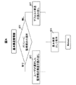
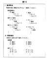
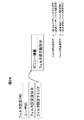
図4は本実施形態の基本構造管理部102の処理手順を示すフローチャートである。ステップ401で基本構造管理部102は、ポリシー項目DB111を参照して、監視視点をポリシー項目として扱っているかどうかを調べ、監視視点をポリシー項目として扱っている場合にはステップ402へ進み、監視視点をポリシー項目として扱っていない場合にはステップ403へ進む。
【0032】
ステップ402では、ユーザによって設定された監視視点の構造を前記ユーザポリシーDB112から読み出す。またステップ403では、デフォルト構造として設定されている監視視点の構造を読み出す。ステップ404では、前記読み出した監視視点の構造を、プログラムやリソースを監視する為の基本構造として基本構造DB113に保存する。
【0033】
図5は本実施形態の関係管理部103の処理手順を示すフローチャートである。ステップ501で関係管理部103は、構成情報管理DB114中の業務情報所在で示される業務コンピュータ120の業務情報取得部121へ処理要求を行い、その業務コンピュータ120の業務処理部122の処理で用いられているプログラムやリソースを示す業務情報DB123へアクセスする。
【0034】
ステップ502では、データ変換DB115を基に、読み出すべき「親項目」と「子項目」の照会元の種別名を照会先の種別名に置換した後、ステップ503では、前記置換した照会先の種別名を用いて業務情報DB123へのアクセスを行い、「親項目」と「子項目」のペア1組を業務情報DB123から読み出す。
【0035】
ステップ504では、前記読み出した1組のデータをそれぞれデータ変換DB115を基に、照会元の項目名に置換した後、ステップ505では、照会元の項目名へ置換済のデータ1組を相関関係DB116へ保存する。
【0036】
ステップ506では、次のデータが業務情報DB123中に有るかどうかを調べ、次のデータが有る場合にはステップ503へ戻り、次のデータが無い場合にはステップ507へ進む。またステップ507では、構成情報管理DB114中に次の業務情報の所在を示す情報が有るかどうかを調べ、次の業務情報の所在情報が有る場合にはステップ501へ戻る。
【0037】
図6は本実施形態の監視構造生成部104の処理手順を示すフローチャートである。ステップ601で監視構造生成部104は、まず監視構造DB117中の前記ユーザIDに対応する構造項番「0」のレコードの項目名称に「ルート」を設定する。
【0038】
ステップ602では、ポリシー項目DB111を参照し、監視項目をポリシーの項目として扱っているかどうかを調べ、監視項目をポリシー項目として扱っている場合にはステップ603へ進み、扱っていない場合にはステップ604へ進む。
【0039】
ステップ603では、相関関係DB116から「親項目」及び「子項目」が監視対象であるデータを抽出した後、ステップ604では、前記設定された基本構造の第一階層に属する種別の項目を抽出済データから検出し、ステップ605では、前記検出された項目を監視構造DB117の第一階層に追加する。
【0040】
ステップ606では、追加した項目と関係のある項目の内、基本構造の次の階層に属する種別の項目を抽出済データから検出し、ステップ607では、前記検出された項目を監視構造DB117の次の階層に追加する。
【0041】
ステップ608では、前記基本構造を参照して次の階層が有るかどうかを調べ、次の階層が有る場合にはステップ606へ戻り、次の階層が無い場合にはステップ609へ進む。
【0042】
ステップ609では、前記追加の行われた監視構造DB117のレコードをメモリ上に一時的に格納して最下層からグループ構造になる様に並び替えた後、ステップ610では、前記並び替えを行ったレコードを監視構造DB117に保存する。
【0043】
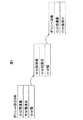
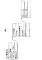
図7は本実施形態のポリシー項目DB111のデータ構造を示す図である。図7に示す様に本実施形態のポリシー項目DB111は、大分類に該当する項目の番号を示す大分類項番、その項目名を示す大分類項目、大分類の次に分類される中分類の情報として、その中分類に該当する項目の番号を示す中分類項番とその項目名である中分類項目、中分類の次に分類される小分類の情報として、そのポリシー項目の番号を示すポリシー項番と小分類項番と小分類項目を格納する為のデータ構造を有している。
【0044】
図8は本実施形態のユーザポリシーDB112のデータ構造を示す図である。図8に示す様に本実施形態のユーザポリシーDB112は、ユーザを識別する為のユーザID、ユーザポリシーが登録済みであるかどうかを示す登録識別子、ポリシーの選択内容を示すポリシーチェック情報として、ポリシー項目の番号を示すポリシー項番とそのポリシー項目がユーザによって選択されているかどうかを示すチェック識別子を格納する為のデータ構造を有している。
【0045】
図9は本実施形態の基本構造DB113のデータ構造を示す図である。図9に示す様に本実施形態の基本構造DB113は、ユーザを識別する為のユーザID、階層構造を示す情報として、階層を識別する為の番号を示す階層項番と階層の種別を示す階層種別を格納する為のデータ構造を有している。
【0046】
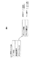
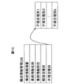
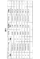
図10は本実施形態の構成情報管理DB114のデータ構造を示す図である。図10に示す様に本実施形態の構成情報管理DB114は、構成情報の番号を示す構成情報項番、前記項番に対応する業務情報の名称を示す業務情報名称、前記項番に対応する業務情報の所在を示す業務情報所在、前記項番に対応する業務情報の親項目の照会元での種別名を示す親項目種別、その子項目の種別名を示す子項目種別として、前記項番に対応する業務情報の子項目の照会元での種別名を示す子項目種別1〜kを格納する為のデータ構造を有している。
【0047】
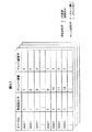
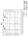
図11は本実施形態の業務情報DB123の1つであるジョブ管理DBのデータ構造を示す図である。図11に示す様に本実施形態の業務情報DB123の1つであるジョブ管理DBは、ジョブグループの番号を示すグループ項番、前記項番のジョブグループの名称を示すジョブグループ名、前記項番のジョブグループの構成する構成ジョブの情報として、ジョブの番号を示すジョブ項番、前記項番のジョブの名称を示すジョブ名、前記項番のジョブの実行が開始される時刻を示す実行開始時刻、前記項番のジョブの実行を行うホストの名称を示すホスト名、前記項番のジョブの実行の際に接続する接続先ストレージの情報として、その名称を示すストレージ1及び2等を格納する為のデータ構造を有している。
【0048】
なお、個々の業務情報DB123は図11に示すジョブ管理DBと同じデータ構造を持つとは限らず、通常、それぞれ別の構造を持つ。各業務コンピュータ120の持つ業務情報DB123のデータ構造は業務情報取得部121が把握しており、関係管理部103の処理で「親項目」と「子項目」の照会依頼が来ると、業務情報取得部121は業務情報DB123の構造を踏まえ、対応するデータを取得し、関係管理部103へ提供する機能を持つ。
【0049】
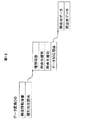
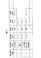
図12は本実施形態のデータ変換DB115のデータ構造を示す図である。図12に示す様に本実施形態のデータ変換DB115は、構成情報の番号を示す構成情報項番、前記項番の構成情報の種別の照会元と照会先での対応関係を示す種別対応関係の情報として、種別の番号を示す種別項番、照会元での種別名を示す照会元種別、照会先での種別名を示す照会先種別、前記項番の構成情報のデータの照会元と照会先での対応関係を示すデータ対応関係の情報として、照会元でのデータ名を示す照会元データ、照会先でのデータ名を示す照会先データを格納する為のデータ構造を有している。
【0050】
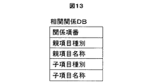
図13は本実施形態の相関関係DB116のデータ構造を示す図である。図13に示す様に本実施形態の相関関係DB116は、相関関係の番号を示す関係項番、前記項番の相関関係における親項目の種別名を示す親項目種別、前記項番の相関関係における親項目の項目名を示す親項目名称、前記親項目に対する子項目の種別名を示す子項目種別、前記親項目に対する子項目の項目名を示す子項目名称を格納する為のデータ構造を有している。
【0051】
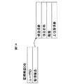
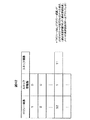
図14は本実施形態の監視構造DB117のデータ構造を示す図である。図14に示す様に本実施形態の監視構造DB117は、ユーザを識別する為のユーザID、前記ユーザIDのユーザの監視構造の情報として、その監視構造の番号を示す構造項番、前記項番に対応する監視項目の名称を示す項目名称、当該監視構造中の前記項番の項目の位置を示す階層、前記項番の項目に対応する「親項目」データの構造項番を示す上位層項番を格納する為のデータ構造を有している。
【0052】
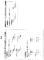
図15は本実施形態のポリシー設定画面の例を示す図である。図15に示す様に本実施形態のポリシー設定画面では、業務指向、サーバ指向やストレージ指向等の監視視点(構造)や、業務やサーバ等の監視項目を選択する為のメニューを表示する。本実施形態では、ユーザがメニュー中にチェックを入力することによりそのポリシー項目を選択できるものとしているが、他の形態によるユーザのポリシー設定方法であっても良い。
【0053】
図16は本実施形態のポリシー項目DB111の例を示す図である。図16のポリシー項目DB111では、大分類項番「1」、大分類項目「監視視点」、中分類項番「1」、中分類項目「業務指向」、ポリシー項番「1」、小分類項番「1」、小分類項目「業務−サーバ−ストレージの基本構造」等を格納する例を表している。
【0054】
図17は本実施形態のユーザポリシーDB112の例を示す図である。図17のユーザポリシーDB112では、ユーザID「0001」、登録識別子「1」、ポリシー項番「1」、チェック識別子「1」等を格納する例を表している。
【0055】
図18は本実施形態の基本構造DB113の例を示す図である。図18の基本構造DB113では、ユーザID「0001」、階層項番「0」、階層種別「ルート」等を格納する例を表している。
【0056】
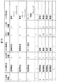
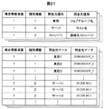
図19は本実施形態の構成情報管理DB114の例を示す図である。図19の構成情報管理DB114では、構成情報項番「1」、業務情報名称「ジョブ管理」、業務情報所在「サーバ1」、親項目種別「業務」、子項目種別「サーバ」及び「ストレージ」を格納する例を表している。
【0057】
図20は本実施形態の業務情報DB123の例として、ジョブ管理DBの例を示す図である。図20の業務情報DB123のジョブ管理DBでは、グループ項番「1」、ジョブグループ名「JOBGROUP_1」、ジョブ項番「1」、ジョブ名「Job001」、実行開始時刻「12:00」、ホスト名「10.208.40.1」、接続先ストレージ「STR_02」等を格納する例を表している。
【0058】
図21は本実施形態のデータ変換DB115の例を示す図である。図21のデータ変換DB115では、構成情報項番「1」、種別項番「1」、照会元種別「業務」、照会先種別「ジョブグループ名」、照会元データ「業務1」、照会先データ「JOBGROUP_1」等を格納する例を表している。
【0059】
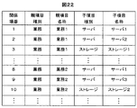
図22は本実施形態の相関関係DB116の例を示す図である。図22の相関関係DB116では、関係項番「1」、親項目種別「業務」、親項目名称「業務1」、子項目種別「サーバ」、子項目名称「サーバ1」等を格納する例を表している。
【0060】
図23は本実施形態の監視構造DB117の例を示す図である。図23の監視構造DB117では、ユーザID「0001」、構造項番「0」、項目名称「ルート」、階層「0」、上位層項番「−−−」等を格納する例を表している。
【0061】
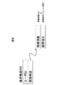
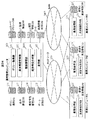
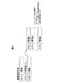
図24は本実施形態の最終生成物である監視構造の一例として、監視ツリーの表示例を示す図である。図24の監視ツリーでは、図23の監視構造例を監視ツリーとして表示した場合の表示例を表しており、図15のポリシー設定例でユーザの選択した業務指向の基本構造に従って、各業務コンピュータ120での業務、サーバ及びストレージを監視する為の監視ツリーが、業務1、サーバ1、ストレージ1等の順で形成されている。
【0062】
前記の様に本実施形態の運用管理システムでは、各業務コンピュータ120で用いられているプログラムやリソースを示す業務情報DB123をデータ変換DB115の情報によって置換して相関関係を求め、当該プログラムやリソースを監視する為の監視構造情報を生成するので、各業務コンピュータ120での業務処理の為に用意されている業務情報DB123から監視構造を効率的に生成することができる。
【0063】
また本実施形態の運用管理システムでは、ユーザ毎に選択されたポリシーに基づき、必要な情報をシステム上の各業務コンピュータから収集し、ユーザのニーズに合った監視構造(例えば監視ツリー)を生成するので、ユーザの見たい視点や監視したい項目等に応じた監視構造を効率的に生成することができる。
【0064】
以上説明した様に本実施形態の運用管理装置によれば、各コンピュータで用いられているプログラムやリソースを示す業務情報から当該プログラムやリソースを監視する為の監視構造情報を生成するので、プログラムと特定のリソースとを関係付けた監視構造や特定のリソースと他のリソースとを関係付けた監視構造等の各種構造を示す監視構造情報を効率的に生成することが可能である。
【0065】
(実施形態2)
以下に業種や権限等に応じてユーザ毎にポリシーメニューを変更する実施形態2の運用管理装置について説明する。
【0066】
図25は本実施形態の運用管理装置の概略構成を示す図である。図25に示す様に本実施形態の運用管理コンピュータ100は、フィルタ設定部2501と、ポリシー取得部2502とを有している。
【0067】
フィルタ設定部2501は、ポリシーを選択する為のメニューの内容をユーザ毎に変更する為のフィルタ情報をフィルタ設定DB2503へ設定する処理部である。ポリシー取得部2502は、フィルタ設定DB2503中のフィルタ情報に応じてフィルタリングされたメニューからユーザによって選択されたポリシーを取得する処理部である。
【0068】
運用管理コンピュータ100をフィルタ設定部2501及びポリシー取得部2502として機能させる為のプログラムは、CD−ROM等の記録媒体に記録され磁気ディスク等に格納された後、メモリにロードされて実行されるものとする。なお前記プログラムを記録する記録媒体はCD−ROM以外の他の記録媒体でも良い。また前記プログラムを当該記録媒体から情報処理装置にインストールして使用しても良いし、ネットワークを通じて当該記録媒体にアクセスして前記プログラムを使用するものとしても良い。
なお実施形態の他の処理部の構成については実施形態1と同様であるものとする。
【0069】
図26は本実施形態のフィルタリング実行時のポリシー設定画面例を示す図である。図26に示す様に本実施形態のポリシー設定画面では、監視視点として業務指向のみ、監視項目の業務として「業務1」のみを選択する為のメニューを表示しており、図15の例における監視視点のサーバ指向やストレージ指向、また業務2、業務3等をフィルタリングしている例である。
【0070】
図27は本実施形態のフィルタ設定部2501の処理手順を示すフローチャートである。ステップ2701でフィルタ設定部2501は、フィルタ情報を設定する設定者を識別する為の設定者IDを取得し、ステップ2702では、フィルタの設定が行われるユーザを識別する為の設定対象ユーザIDを取得する。
【0071】
ステップ2703では、前記設定者IDで識別される設定者に前記設定対象ユーザへのフィルタ設定権限が有るかどうかを調べ、設定権限が有る場合にはステップ2704へ進み、設定権限が無い場合にはステップ2709で、設定権限が無いことを示すエラーメッセージを表示する。
【0072】
ステップ2704では、前記設定対象ユーザIDのフィルタ設定識別子に、フィルタ設定が有ることを示すフラグ設定として「1」を設定した後、ステップ2705では、前記設定者に対してフィルタ設定の入力を要求し、ステップ2706では、前記設定者から入力されたフィルタ情報の設定結果を取得する。
【0073】
なお、フィルタ設定識別子は当該ユーザに対しフィルタ設定が行われるかどうかを識別するための識別子であり、本実施形態では、その値が「0」か「1」かで未設定、登録済みを識別する方法を採っているが、他の識別方法で識別しても良い。
【0074】
ステップ2707では、前記設定対象ユーザID及び前記設定したフィルタ設定識別子と前記取得したフィルタ情報の設定内容をフィルタ設定DB2503へ保存する。
【0075】
ステップ2708では、別のユーザに対してフィルタ情報の設定を行うことを示す入力が行われているかどうかを調べ、別のユーザにもフィルタ情報を設定することを示す入力が行われている場合にはステップ2702へ戻り、別のユーザにフィルタ情報を設定しないことを示す入力が行われている場合には処理を終了する。
【0076】
図28は本実施形態のポリシー取得部2502の処理手順を示すフローチャートである。ステップ2801でポリシー取得部2502は、ポリシーの取得が行われるユーザを識別する為のユーザIDを取得する。
【0077】
ステップ2802では、ユーザポリシーDB112を参照して前記取得したユーザIDに対応する登録識別子を読み出し、その登録識別子に「1」が設定されているかどうかを判定することによりユーザポリシーの登録有無を調べ、未設定である場合にはステップ2805へ進み、設定済みである場合にはステップ2803へ進む。
【0078】
ステップ2803では、ポリシーを更新するかどうかを示す入力を受け付け、更新を行うことを示す入力を受け付けた場合にはステップ2805へ進み、更新を行わないことを示す入力を受け付けた場合にはステップ2804へ進む。ステップ2804では、設定済みのユーザポリシーを読み出して処理を終了する。
【0079】
ステップ2805では、フィルタ設定DB2503のフィルタ設定識別子を参照して当該ユーザに対するフィルタ設定の有無を調べ、フィルタ設定が行われている場合にはステップ2806へ進み、フィルタ設定が行われていない場合にはステップ2807へ進む。
【0080】
ステップ2806では、フィルタ設定DB2503中のフィルタ項目識別子を参照し、前記ポリシー項目の内でフィルタ設定の行われていないポリシー項目のみから成るメニューを生成して表示する。またステップ2807では、全てのポリシー項目を含むメニューを生成して表示する。
ステップ2808では、前記表示されたメニューからユーザによって選択された内容の入力を受け付けることにより、ユーザポリシーを取得する。
【0081】
ステップ2809では、前記取得したユーザポリシーの内容をチェックして矛盾があるかどうかを調べ、矛盾が無い場合にはステップ2810へ進み、矛盾が有る場合にはステップ2812へ進む。
【0082】
ステップ2810では、ユーザポリシーDB112中の前記ユーザIDに対応する登録識別子に「1」を設定し、ステップ2811では、前記取得したユーザポリシーをユーザポリシーDB112中に保存する。またステップ2812では、入力されたユーザポリシーに矛盾があることを示すエラーメッセージを表示する。
【0083】
図29は本実施形態のフィルタ設定DB2503のデータ構造を示す図である。図29に示す様に本実施形態のフィルタ設定DB2503は、ユーザを識別する為のユーザID、そのユーザに対してフィルタ情報の設定が行われているかどうかを示すフィルタ設定識別子、フィルタ情報の設定内容を示すフィルタ設定チェック情報として、ポリシー項目の番号を示すポリシー項番とその項番のポリシー項目に対してフィルタ設定が行われているかどうかを示すフィルタ項目識別子を格納する為のデータ構造を有している。
【0084】
図30は本実施形態のフィルタ設定DB2503の例を示す図である。図30のフィルタ設定DB2503では、ユーザID「0001」、フィルタ設定識別子「1」、ポリシー項番「3」及びフィルタ項目識別子「1」等を格納する例を表しており、ユーザID「0001」のユーザに対してポリシー項番「3」のポリシー項目に対してフィルタが設定されていることが判る。
【0085】
前記の様に本実施形態の運用管理では、業種や権限等に応じてユーザ毎にポリシーメニューを変えている。これはユーザ自身がポリシーで監視項目をフィルタリングするのではなく、ユーザ以外の権限のある人(通常はシステム管理者等)が各ユーザに不要なポリシー項目を事前に非表示に設定することによるアクセス制御である。
【0086】
以上説明した様に本実施形態の運用管理によれば、ポリシーを選択する為のメニューの内容をユーザ毎に変更することで、明らかにユーザが選択しない項目やユーザに選択させたくない項目を非表示にすることにより不要な情報へのアクセス防止を実現可能である。
【0087】
(実施形態3)
以下に予め設定された内容を用いてポリシーの一部または全部の設定を強制的に行う実施形態3の運用管理装置について説明する。
【0088】
図31は本実施形態の運用管理システムの全体構成を示す図である。図31に示す様に本実施形態の運用管理コンピュータ100は強制ポリシー設定部3101を有している。強制ポリシー設定部3101は、予め設定された内容を用いてポリシーの一部または全部の設定を強制的に行う処理部である。
【0089】
運用管理コンピュータ100を強制ポリシー設定部3101として機能させる為のプログラムは、CD−ROM等の記録媒体に記録され磁気ディスク等に格納された後、メモリにロードされて実行されるものとする。なお前記プログラムを記録する記録媒体はCD−ROM以外の他の記録媒体でも良い。また前記プログラムを当該記録媒体から情報処理装置にインストールして使用しても良いし、ネットワークを通じて当該記録媒体にアクセスして前記プログラムを使用するものとしても良い。
なお実施形態の他の処理部の構成については実施形態2と同様であるものとする。
【0090】
図32は本実施形態の強制ポリシー設定時のポリシー設定画面例(左側)と、強制ポリシーが設定された後で、ユーザに提示されているポリシー設定画面例(右側)を示す図である。なお図32では、強制ポリシー設定者を当該システム全体を管理するシステム管理者、強制ポリシーの設定を受けるユーザを当該システム上で実施されている「業務1」の業務管理者を例として想定している。図32に示す様に本実施形態のユーザに表示されるポリシー設定画面では、監視視点として業務指向のみを選択する為のメニューを表示しており、監視項目等の他の内容についてはシステム管理者により選択されたものが用いられ、ユーザに選択権は与えられない。
【0091】
図33は本実施形態の強制ポリシー設定部3101の処理手順を示すフローチャートである。ステップ3301で強制ポリシー設定部3101は、強制ポリシーの設定を行う設定者を識別する為の設定者IDを取得し、ステップ3302では、強制ポリシーの設定が行われるユーザを識別する為の設定対象ユーザIDを取得する。
【0092】
ステップ3303では、前記設定者IDで識別される設定者に設定権限が有るかどうかを調べ、設定権限が有る場合にはステップ3304へ進み、設定権限が無い場合にはステップ3312へ進む。
【0093】
ステップ3304では、前記設定対象ユーザIDのフィルタ設定識別子に、フィルタ設定が有ることを示すフラグ設定として「1」を設定した後、ステップ3305では、前記設定者に対してフィルタ設定の入力を要求し、ステップ3306では、前記設定者から入力されたフィルタ情報の設定結果を取得する。
【0094】
ステップ3307では、前記設定対象ユーザID及び前記設定したフィルタ設定識別子と前記取得したフィルタ設定の内容をフィルタ設定DB2503へ保存する。
【0095】
ステップ3308では、前記の様にしてフィルタ設定を行ったポリシー項目のみを再度表示し、ステップ3309では、前記表示分について強制ポリシーの入力受付、即ちフィルタ設定によりユーザには表示されないポリシー項目についてポリシーの設定を受け付ける。そしてステップ3310では、前記受け付けたユーザポリシー(強制ポリシー)の内容を、前記設定対象ユーザIDに対応するユーザポリシーとしてユーザポリシーDB112へ保存する。
【0096】
ステップ3311では、別のユーザにも強制ポリシーを設定することを示す入力が行われているかどうかを調べ、別のユーザにも強制ポリシーを設定することを示す入力が行われている場合にはステップ3302へ戻り、別のユーザには強制ポリシーを設定しないことを示す入力が行われている場合には処理を終了する。
【0097】
前記の様に本実施形態の運用管理システムでは、ポリシーの一部若しくは全部をユーザ以外で権限のある人が設定することを可能にしており、例えば監視項目はユーザが設定するまでもなく、システム全体の管理者が各ユーザに関係のある監視項目を予め設定しておけば、ユーザが設定する項目が少なくて済む。システム全体の管理者がユーザの権限や分掌に応じたポリシーを事前に設定しておくことにより、業務分掌等から明らかな監視項目の選択をユーザが選択すべき監視視点等のポリシーと切り離すことで、ユーザのポリシー設定における負担を軽減することができる。
【0098】
以上説明した様に本実施形態の運用管理装置によれば、予め設定された内容を用いて前記ポリシーの一部または全部の設定を行うので、ポリシーの設定におけるユーザの作業負担を軽減することが可能である。
【0099】
(実施形態4)
以下に業務情報をミラーリングした業務情報統合DBにより相関関係情報を生成する実施形態4の運用管理装置について説明する。
【0100】
図34は本実施形態の運用管理システムの全体構成を示す図である。図34に示す様に本実施形態の運用管理コンピュータ100は関係管理部3401を有している。関係管理部3401は、各業務コンピュータの業務情報をミラーリングした業務情報統合DB3402により相関関係情報を生成する処理部である。
【0101】
運用管理コンピュータ100を関係管理部3401として機能させる為のプログラムは、CD−ROM等の記録媒体に記録され磁気ディスク等に格納された後、メモリにロードされて実行されるものとする。なお前記プログラムを記録する記録媒体はCD−ROM以外の他の記録媒体でも良い。また前記プログラムを当該記録媒体から情報処理装置にインストールして使用しても良いし、ネットワークを通じて当該記録媒体にアクセスして前記プログラムを使用するものとしても良い。
なお実施形態の他の処理部の構成については実施形態1と同様であるものとする。
【0102】
図35は本実施形態の関係管理部3401の処理手順を示すフローチャートである。ステップ3501で関係管理部3401は、構成情報管理DB114中の業務情報所在で示される業務コンピュータ120の各業務情報DB123の代わりに業務情報統合DB3402へアクセスする。
【0103】
ステップ3502では、データ変換DB115を基に、読み出すべき「親項目」と「子項目」の照会元の種別名を照会先の種別名に置換した後、ステップ3503では、前記置換した照会先の種別名を用いて業務情報統合DB3402から、「親項目」と「子項目」のペア1組を読み出す。
【0104】
ステップ3504では、前記読み出した1組のデータをそれぞれデータ変換DB115を基に、照会元の項目名に置換した後、ステップ3505では、照会元の項目名へ置換済のデータ1組を相関関係DB116へ保存する。
【0105】
ステップ3506では、次のデータが業務情報統合DB3402の業務情報中に有るかどうかを調べ、次のデータが有る場合にはステップ3503へ戻り、次のデータが無い場合にはステップ3507へ進む。
【0106】
ステップ3507では、構成情報管理DB114中に次の業務情報の所在を示す情報が有るかどうかを調べ、次の業務情報の所在情報が有る場合にはステップ3502へ戻る。
【0107】
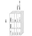
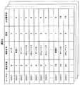
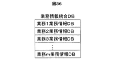
図36は本実施形態の業務情報統合DB3402のデータ構造を示す図である。図36に示す様に本実施形態の業務情報統合DB3402は、各業務コンピュータの持つ業務情報DB123の内容を格納する為のデータ構造を有している。
【0108】
なお各業務コンピュータ120の持つ業務情報DB123のデータ構造は業務情報取得部121が把握しており、業務情報統合DB3403へデータ取得依頼を出す際に、一旦、各業務コンピュータ120の業務情報取得部121にデータ構造を照会する必要がある。また、業務情報取得部121は業務コンピュータ120ではなく、運用管理コンピュータ100内に各業務コンピュータ120の業務情報取得部121の機能を集約して配置しても良い。
【0109】
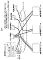
前記の様に本実施形態の運用管理システムでは、各種業務コンピュータの業務構成情報を一括して保持する業務情報統合DB3402を置き、それを各業務の業務情報DB123とSANで繋いでミラーリングして、常に最新情報を維持することにより、監視構造の作成に必要な情報をLAN(Local Area Network)を経由せずに入手でき、ネットワーク負荷を軽減することが可能である。また各業務の業務情報DB123へは各業務管理者のみがアクセスし、業務情報統合DB3402には運用管理者のみがアクセスするという運用も可能であり、情報読み込みの高速化や当該業務の業務管理者のみに業務情報DB123へのアクセスを制限できる。
【0110】
以上説明した様に本実施形態の運用管理装置によれば、業務情報をSANなどのストレージ技術を適用しミラーリングした業務情報統合DBにより相関関係情報を生成するので、ネットワーク負荷を軽減し、情報読み込みを高速化すると共に、各コンピュータ上の業務情報へのアクセスを制限することが可能である。
【0111】
(実施形態5)
以下に業務情報の変更を検出して監視構造情報を更新する実施形態5の運用管理装置について説明する。
【0112】
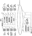
図37は本実施形態の運用管理システムの全体構成を示す図である。図37に示す様に本実施形態の運用管理コンピュータ100は監視構造自動更新部3701を有している。監視構造自動更新部3701は、業務コンピュータに配置したDB変更監視部3702が業務情報の変更を検出したのを契機に監視構造情報を更新する処理部である。
【0113】
運用管理コンピュータ100を監視構造自動更新部3701として機能させる為のプログラムは、CD−ROM等の記録媒体に記録され磁気ディスク等に格納された後、メモリにロードされて実行されるものとする。なお前記プログラムを記録する記録媒体はCD−ROM以外の他の記録媒体でも良い。また前記プログラムを当該記録媒体から情報処理装置にインストールして使用しても良いし、ネットワークを通じて当該記録媒体にアクセスして前記プログラムを使用するものとしても良い。
なお実施形態の他の処理部の構成については実施形態1と同様であるものとする。
【0114】
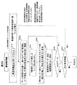
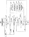
図38は本実施形態の監視構造自動更新部3701の処理手順を示すフローチャートである。ステップ3801で監視構造自動更新部3701は、終了コマンドの入力を受け付けているかどうかを調べ、終了コマンドの入力を検知している場合には処理を終了し、終了コマンドの入力を検知していない場合にはステップ3802へ進む。
【0115】
ステップ3802では、現在ログインしているユーザがいるかどうかを調べ、ログインユーザが有る場合にはステップ3803へ進み、ログインユーザが無い場合にはステップ3812で所定時間待機した後、ステップ3801へ戻る。
【0116】
ステップ3803では、業務コンピュータに配置したDB変更監視部3702が各業務コンピュータの業務情報DB123の更新日時を前回のものと比較する等して、業務情報DB123が変更されたかどうかを調べ、業務情報DB123の変更を検知した場合にはステップ3804へ進み、業務情報DB123の変更を検知していない場合にはステップ3812で所定時間待機する。
【0117】
ステップ3804では、ログイン中のユーザを識別する為のユーザIDの取得を行う。そしてステップ3805では、ユーザポリシーDB112を参照して前記取得したユーザIDに対応する登録識別子を読み出し、その登録識別子に「1」が設定されているかどうかを判定することによりユーザポリシーの登録有無を調べ、未設定である場合にはステップ3811へ進み、設定済みである場合にはステップ3806へ進む。
【0118】
ステップ3806では、前記ユーザIDに対応する設定済ユーザポリシーをユーザポリシーDB112から読み出し、ステップ3807では、前記設定済ユーザポリシーから基本構造の読み出しを行う。
【0119】
そしてステップ3808では、関係管理部103の処理を行い、ステップ3809では、監視構造生成部104の処理を行って、ステップ3810では、更新済の監視構造の表示を行う。なおステップ3808〜ステップ3810の詳細は他の実施形態に示したものと同様であるものとするが、業務情報DB123の変更前後の差分により当該ユーザの監視構造情報の変更前後の差分情報を生成し、既存の監視構造情報に対して前記差分情報の追加または削除を行うことにより、更新後の監視構造情報を生成するものとしても良い。
【0120】
ステップ3811では、他にログインしているユーザがいるかどうかを調べ、他のログインユーザが有る場合にはステップ3804へ戻り、他のログインユーザが無い場合には処理を終了する。
【0121】
前記の様に本実施形態の運用管理システムでは、運用管理コンピュータや各業務コンピュータに配置したDB変更監視部3702が業務情報DB123の更新を検出することにより、それをトリガーとして、監視構造の更新を自動的に実施することができる。
【0122】
以上説明した様に本実施形態の運用管理装置によれば、業務情報の変更を検出して監視構造情報を更新するので、各コンピュータ上の業務情報の変更に応じて監視構造の変更を行うことが可能である。
【0123】
(実施形態6)
以下にポリシーによって選択された監視項目に関係する業務プログラムまたはリソースを示す業務情報のみを参照して相関関係情報を生成する実施形態6の運用管理装置について説明する。
【0124】
図39は本実施形態の運用管理システムの全体構成を示す図である。図39に示す様に本実施形態の運用管理コンピュータ100は関係管理部3901を有している。関係管理部3901は、ポリシーによって選択された監視項目に関係するプログラムまたはリソースを示す業務情報のみを参照して相関関係情報を生成する処理部である。
【0125】
運用管理コンピュータ100を関係管理部3901として機能させる為のプログラムは、CD−ROM等の記録媒体に記録され磁気ディスク等に格納された後、メモリにロードされて実行されるものとする。なお前記プログラムを記録する記録媒体はCD−ROM以外の他の記録媒体でも良い。また前記プログラムを当該記録媒体から情報処理装置にインストールして使用しても良いし、ネットワークを通じて当該記録媒体にアクセスして前記プログラムを使用するものとしても良い。
なお実施形態の他の処理部の構成については実施形態1と同様であるものとする。
【0126】
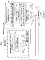
図40は本実施形態の関係管理部3901の処理手順を示すフローチャートである。ステップ4001で関係管理部3901は、情報選択DB3902を基にスキップすべき業務情報をリストアップした後、ステップ4002では、1つ目の業務情報についてスキップ対象であるかどうかを確認する。
【0127】
ステップ4003では、前記確認結果を参照してその業務情報がスキップ対象であるかどうかを調べ、スキップ対象である場合にはステップ4010へ進み、スキップ対象でない場合にはステップ4004へ進む。
【0128】
ステップ4004では、構成情報管理DB114中の業務情報所在で示される業務コンピュータ120の業務情報取得部121へ処理要求を行い、その業務コンピュータ120の業務処理部122の処理で用いられているプログラムやリソースを示す業務情報DB123へアクセスする。
【0129】
ステップ4005では、データ変換DB115を基に、読み出すべき「親項目」と「子項目」の照会元の種別名を照会先の種別名に置換した後、ステップ4006では、前記置換した照会先の種別名を用いて業務情報DB123から「親項目」と「子項目」のペア1組を読み出す。
【0130】
ステップ4007では、前記読み出した1組のデータをそれぞれデータ変換DB115を基に、照会元の項目名に置換した後、ステップ4008では、照会元の項目名へ置換済のデータ1組を相関関係DB116へ保存する。
【0131】
ステップ4009では、次のデータが業務情報DB123中に有るかどうかを調べ、次のデータが有る場合にはステップ4006へ戻り、次のデータが無い場合にはステップ4010へ進む。
【0132】
ステップ4010では、構成情報管理DB114中に次の業務情報の所在を示す情報が有るかどうかを調べ、次の業務情報の所在情報が有る場合にはステップ4003へ戻る。
【0133】
図41は本実施形態の情報選択DB3902のデータ構造を示す図である。図41に示す様に本実施形態の情報選択DB3902は、ポリシー項目の番号を示すポリシー項番、前記ポリシー項番のポリシー項目がユーザによって選択されなかった場合にスキップされる業務情報の数を示すスキップ情報数、スキップ対象を示すスキップ項番の情報として、スキップされる業務情報の構成情報項番を示すスキップ項番を格納する為のデータ構造を有している。
【0134】
図42は本実施形態の情報選択DB3902の例を示す図である。図42の情報選択DB3902は、ポリシー項番「32」、スキップ情報数「1」、スキップ項番「11」等を格納する例を表している。
【0135】
前記の様に本実施形態の運用管理システムでは、設定したポリシーに応じて読み込みに行く業務情報DB123を変更するので、例えばクラスタ構成に応じた監視が不要である場合にはクラスタ製品設定情報へのアクセスを省略する等、不要な業務情報へのアクセスを省略して監視構造情報の生成を効率化することができる。
【0136】
以上説明した様に本実施形態の運用管理装置によれば、設定したポリシーに関係のあるプログラムまたはリソースを示す業務情報のみを参照して相関関係情報を生成するので、不要な業務情報の参照を省略して相関関係情報の生成を効率化することが可能である。
【0137】
【発明の効果】
本発明によれば各コンピュータで用いられているプログラムやリソースを示す業務情報を活用して当該プログラムやリソースを監視する為の監視構造情報を生成するので、プログラムと特定のリソースとを関係付けた監視構造や特定のリソースと他のリソースとを関係付けた監視構造等の各種構造を示す監視構造情報を効率的に生成することが可能である。また、ユーザ毎に異なるシステム監視へのニーズに対応し、ユーザに適した監視構造を生成することが可能である。
【図面の簡単な説明】
【図1】実施形態1の運用管理システムの全体構成を示す図である。
【図2】実施形態1の全体の処理手順を示すフローチャートである。
【図3】実施形態1のポリシー取得部101の処理手順を示すフローチャートである。
【図4】実施形態1の基本構造管理部102の処理手順を示すフローチャートである。
【図5】実施形態1の関係管理部103の処理手順を示すフローチャートである。
【図6】実施形態1の監視構造生成部104の処理手順を示すフローチャートである。
【図7】実施形態1のポリシー項目DB111のデータ構造を示す図である。
【図8】実施形態1のユーザポリシーDB112のデータ構造を示す図である。
【図9】実施形態1の基本構造DB113のデータ構造を示す図である。
【図10】実施形態1の構成情報管理DB114のデータ構造を示す図である。
【図11】実施形態1の業務情報DB123のデータ構造を示す図である。
【図12】実施形態1のデータ変換DB115のデータ構造を示す図である。
【図13】実施形態1の相関関係DB116のデータ構造を示す図である。
【図14】実施形態1の監視構造DB117のデータ構造を示す図である。
【図15】実施形態1のポリシー設定画面の例を示す図である。
【図16】実施形態1のポリシー項目DB111の例を示す図である。
【図17】実施形態1のユーザポリシーDB112の例を示す図である。
【図18】実施形態1の基本構造DB113の例を示す図である。
【図19】実施形態1の構成情報管理DB114の例を示す図である。
【図20】実施形態1の業務情報DB123の例を示す図である。
【図21】実施形態1のデータ変換DB115の例を示す図である。
【図22】実施形態1の相関関係DB116の例を示す図である。
【図23】実施形態1の監視構造DB117の例を示す図である。
【図24】実施形態1の監視ツリーの表示例を示す図である。
【図25】実施形態2の運用管理装置の概略構成を示す図である。
【図26】実施形態2のフィルタリング実行時のポリシー設定画面例を示す図である。
【図27】実施形態2のフィルタ設定部2501の処理手順を示すフローチャートである。
【図28】実施形態2のポリシー取得部2502の処理手順を示すフローチャートである。
【図29】実施形態2のフィルタ設定DB2503のデータ構造を示す図である。
【図30】実施形態2のフィルタ設定DB2503の例を示す図である。
【図31】実施形態3の運用管理システムの全体構成を示す図である。
【図32】実施形態3の強制ポリシー設定時のポリシー設定画面例を示す図である。
【図33】実施形態3の強制ポリシー設定部3101の処理手順を示すフローチャートである。
【図34】実施形態4の運用管理システムの全体構成を示す図である。
【図35】実施形態4の関係管理部3401の処理手順を示すフローチャートである。
【図36】実施形態4の業務情報統合DB3402のデータ構造を示す図である。
【図37】実施形態5の運用管理システムの全体構成を示す図である。
【図38】実施形態5の監視構造自動更新部3701の処理手順を示すフローチャートである。
【図39】実施形態6の運用管理システムの全体構成を示す図である。
【図40】実施形態6の関係管理部3901の処理手順を示すフローチャートである。
【図41】実施形態6の情報選択DB3902のデータ構造を示す図である。
【図42】実施形態6の情報選択DB3902の例を示す図である。
【符号の説明】
100…運用管理コンピュータ、111…ポリシー項目DB、112…ユーザポリシーDB、113…基本構造DB、114…構成情報管理DB、115…データ変換DB、116…相関関係DB、117…監視構造DB、120…業務コンピュータ、121…業務情報取得部、122…業務処理部、123…業務情報DB、130…ネットワーク、101…ポリシー取得部、102…基本構造管理部、103…関係管理部、104…監視構造生成部、105…表示部、2503…フィルタ設定DB、2501…フィルタ設定部、2502…ポリシー取得部、3101…強制ポリシー設定部、3402…業務情報統合DB、3403…SAN、3401…関係管理部、3701…監視構造自動更新部、3902…情報選択DB、3901…関係管理部。[0001]
TECHNICAL FIELD OF THE INVENTION
The present invention relates to an operation management device that monitors the status of programs and resources and manages the operation of a computer system, and in particular, generates a monitoring structure such as a monitoring tree for monitoring programs and resources that perform business processes and implements a computer system. The present invention relates to a technology that is effective when applied to operation management for performing operation management.
[0002]
[Prior art]
In the integrated system operation management that manages the operation of the computer system, various resources (servers, applications, databases, network devices, storage devices, etc.) existing in the system are operated and organized in order to understand the scope of the effects of the system failure. -There is a demand for a method of managing / monitoring a system by grouping and hierarchizing applications and the like from the viewpoint of business. In this case, “business configuration definition work” for grouping resources into meaningful units such as business is required in advance. Conventionally, the following method is used.
[0003]
In other words, resources that exist in the system are displayed as icons, and a method for manually grouping resource icons that constitute a certain task by the user, and an attribute rule for specifying the resources that constitute the task are defined by the user. Is a method of defining a business configuration by manually defining the resources and automatically extracting resources constituting the business based on the rules.
[0004]
In general, only a predetermined structure is used as a monitoring structure such as a monitoring tree, and it is not easy to freely change the monitoring structure for each user. For example, in the invention of
[0005]
[Patent Document 1]
JP 2000-181756 A
[0006]
[Problems to be solved by the invention]
In the task configuration definition work of the related art, the user must manually perform grouping of resource icons and definition of attribute rules for specifying resources constituting the task, and repeat the process by the number of tasks. Since it is necessary to execute the task, there is a problem that the larger the system scale, the more complicated the task configuration definition work by the user becomes and the higher the load becomes.
Further, in the related art, when creating a monitoring structure for monitoring a program or a resource, there is a problem that it is not considered to create a different monitoring structure according to a user's needs.
[0007]
An object of the present invention is to solve the above problems and efficiently use monitoring structure information indicating various structures such as a monitoring structure relating a program to a specific resource and a monitoring structure relating a specific resource to another resource. It is an object of the present invention to provide a technology that can be generated dynamically. Another object of the present invention is to provide a monitoring structure suitable for a user in consideration of a monitoring target range and authority for each user, prevent access to unnecessary information, and reduce a user's setting work burden. Reduce the load on the network and speed up the reading of information, change the monitoring structure in response to changes in the business information on each computer, and omit unnecessary business information references to correlate information It is an object of the present invention to provide a technology that enables either of the above-mentioned methods to increase the efficiency of the generation.
[0008]
[Means for Solving the Problems]
The present invention relates to a monitoring structure for monitoring a program or a resource from business information indicating a program or a resource used in each computer in an operation management for monitoring an operation of a computer system by monitoring a state of the program or a resource. It generates information.
[0009]
In the operation management of the present invention, a menu of “policy” is displayed in order to grasp the monitoring needs and preferences of each user, and information selected by the user is managed in a DB (Database).
[0010]
Here, the policy indicates a criterion for generating a monitoring structure, and a resource (eg, job group or business application), a domain, an organization / business division, a region / location information to be monitored is a group of resources to be monitored. Grouping policy for grouping, monitoring item policy for selecting monitoring target items (business and resources, etc.) according to the division of users, etc., monitoring based on what you want to monitor the system (for example, business-centric, server-centric) Virtual policy such as a monitoring viewpoint policy that changes the hierarchical structure of a server, cluster support (virtualization of multiple servers), SAN (Storage Area Network) support (virtualization of multiple storages), VLAN (Virtual LAN) support (network virtualization), etc. There is a virtualization policy that incorporates the contents of the virtualization into the monitoring structure.
[0011]
Next, in accordance with the set policy, management data of other management product groups (job management, network management, application management, etc.) used in each computer, and business configuration information such as cluster product setting information are included. It collects existing business information and generates and manages correlation information indicating the correlation between programs and resources of each computer.
[0012]
Then, the generated correlation information is merged according to the basic structure of monitoring according to the user's policy, and monitoring structure information indicating a structure for monitoring the program or the resource is generated, thereby meeting the needs of the user. A monitoring structure (for example, a monitoring tree) is generated. Through these processes, it is possible to automatically generate a monitoring structure according to the viewpoint that the user wants to view, the item that the user wants to monitor, and the like, based on the business information of each computer.
[0013]
Further, the content of the menu for selecting the policy may be changed for each user according to the type of business, authority, etc., or the setting of part or all of the policy may be forcibly performed according to the preset content. It is good. This makes it possible to hide items that the user clearly does not select or items that the user does not want to select, and reduce the user's setting work load.
[0014]
As described above, according to the operation management of the present invention, the monitoring structure information for monitoring the program and the resource is generated from the business information indicating the program and the resource used in each computer. It is possible to efficiently generate monitoring structure information indicating various structures, such as a monitoring structure that relates a specific resource to another resource and a monitoring structure that relates a specific resource to another resource.
[0015]
BEST MODE FOR CARRYING OUT THE INVENTION
(Embodiment 1)
The operation management apparatus according to the first embodiment that collects necessary information from each business computer on the system based on a policy selected for each user and generates a monitoring structure that meets the needs of the user will be described below.
[0016]
FIG. 1 is a diagram showing the overall configuration of the operation management system of the present embodiment. As shown in FIG. 1, the
[0017]
The
[0018]
The
[0019]
A program for causing the
[0020]
FIG. 2 is a flowchart showing the overall processing procedure of the present embodiment. In
[0021]
The policy according to the present embodiment indicates a criterion for generating a monitoring structure for monitoring a program or a resource, and includes a grouping policy, a monitoring item policy, a monitoring viewpoint policy, and a virtualization policy. However, other policies may be added.
[0022]
In
[0023]
In
[0024]
In step 204, the monitoring
In
[0025]
FIG. 3 is a flowchart illustrating a processing procedure of the
[0026]
In
[0027]
In
[0028]
In
[0029]
In
[0030]
On the other hand, in
[0031]
FIG. 4 is a flowchart illustrating a processing procedure of the basic
[0032]
In
[0033]
FIG. 5 is a flowchart illustrating a processing procedure of the
[0034]
In
[0035]
In
[0036]
In
[0037]
FIG. 6 is a flowchart illustrating a processing procedure of the monitoring
[0038]
In step 602, it is checked whether or not the monitoring item is handled as a policy item by referring to the
[0039]
In
[0040]
In
[0041]
In
[0042]
In
[0043]
FIG. 7 is a diagram illustrating a data structure of the
[0044]
FIG. 8 is a diagram illustrating a data structure of the
[0045]
FIG. 9 is a diagram illustrating a data structure of the
[0046]
FIG. 10 is a diagram illustrating a data structure of the configuration
[0047]
FIG. 11 is a diagram illustrating a data structure of a job management DB that is one of the
[0048]
Note that the individual
[0049]
FIG. 12 is a diagram illustrating a data structure of the
[0050]
FIG. 13 is a diagram illustrating a data structure of the
[0051]
FIG. 14 is a diagram illustrating a data structure of the monitoring structure DB 117 according to the present embodiment. As shown in FIG. 14, the monitoring structure DB 117 of the present embodiment includes a user ID for identifying a user, a structure item number indicating the number of the monitoring structure as information on the monitoring structure of the user of the user ID, and the item number. Item name indicating the name of the monitoring item corresponding to the item, the hierarchy indicating the position of the item of the item number in the monitoring structure, and the upper layer item indicating the structure item number of the “parent item” data corresponding to the item of the item number It has a data structure for storing numbers.
[0052]
FIG. 15 is a diagram illustrating an example of the policy setting screen according to the present embodiment. As shown in FIG. 15, on the policy setting screen of the present embodiment, a monitoring viewpoint (structure) such as business-oriented, server-oriented or storage-oriented, and a menu for selecting a monitoring item such as business or server are displayed. In this embodiment, the user can select a policy item by inputting a check in the menu, but a user policy setting method in another form may be used.
[0053]
FIG. 16 is a diagram illustrating an example of the
[0054]
FIG. 17 is a diagram illustrating an example of the
[0055]
FIG. 18 is a diagram illustrating an example of the
[0056]
FIG. 19 is a diagram illustrating an example of the configuration
[0057]
FIG. 20 is a diagram illustrating an example of a job management DB as an example of the
[0058]
FIG. 21 is a diagram illustrating an example of the
[0059]
FIG. 22 is a diagram illustrating an example of the
[0060]
FIG. 23 is a diagram illustrating an example of the monitoring structure DB 117 according to the present embodiment. The monitoring structure DB 117 in FIG. 23 shows an example in which a user ID “0001”, a structure item number “0”, an item name “root”, a hierarchy “0”, an upper layer item number “---”, and the like are stored. .
[0061]
FIG. 24 is a diagram illustrating a display example of a monitoring tree as an example of a monitoring structure that is a final product of the present embodiment. The monitoring tree in FIG. 24 shows a display example in which the monitoring structure example in FIG. 23 is displayed as a monitoring tree. In accordance with the business-oriented basic structure selected by the user in the policy setting example in FIG. A monitoring tree for monitoring the business, server, and storage in is formed in the order of
[0062]
As described above, in the operation management system of the present embodiment, the
[0063]
In the operation management system according to the present embodiment, necessary information is collected from each business computer on the system based on a policy selected for each user, and a monitoring structure (for example, a monitoring tree) that meets the needs of the user is generated. Therefore, it is possible to efficiently generate a monitoring structure according to a viewpoint desired by the user, an item desired to be monitored, and the like.
[0064]
As described above, according to the operation management apparatus of the present embodiment, the monitoring structure information for monitoring the programs and resources is generated from the business information indicating the programs and resources used in each computer. It is possible to efficiently generate monitoring structure information indicating various structures, such as a monitoring structure relating a specific resource and a monitoring structure relating a specific resource to another resource.
[0065]
(Embodiment 2)
Hereinafter, an operation management apparatus according to a second embodiment in which a policy menu is changed for each user according to the type of business, authority, and the like will be described.
[0066]
FIG. 25 is a diagram showing a schematic configuration of the operation management device of the present embodiment. As shown in FIG. 25, the
[0067]
The
[0068]
A program for causing the
The configuration of the other processing units in the embodiment is the same as that in the first embodiment.
[0069]
FIG. 26 is a diagram illustrating an example of a policy setting screen when filtering is performed according to the present embodiment. As shown in FIG. 26, on the policy setting screen of the present embodiment, a menu for selecting only the task-oriented as the monitoring viewpoint and only "
[0070]
FIG. 27 is a flowchart illustrating a processing procedure of the
[0071]
In
[0072]
In
[0073]
Note that the filter setting identifier is an identifier for identifying whether or not a filter setting is performed for the user. In the present embodiment, the value is “0” or “1”, which indicates that the user has not yet set or registered. Although this method is adopted, the identification may be performed by another identification method.
[0074]
In
[0075]
In step 2708, it is checked whether or not an input indicating that filter information is to be set for another user is performed. If the input indicating that filter information is to be set for another user is also performed, Returns to step 2702, and terminates the process if the input indicating that the filter information is not set for another user is performed.
[0076]
FIG. 28 is a flowchart illustrating a processing procedure of the
[0077]
In
[0078]
In
[0079]
In
[0080]
In
In step 2808, a user policy is acquired by accepting the input of the content selected by the user from the displayed menu.
[0081]
In
[0082]
In step 2810, the registration identifier corresponding to the user ID in the
[0083]
FIG. 29 is a diagram illustrating a data structure of the
[0084]
FIG. 30 is a diagram illustrating an example of the
[0085]
As described above, in the operation management of the present embodiment, the policy menu is changed for each user according to the type of business, authority, and the like. This means that users do not filter monitoring items by policies themselves, but access by authorized individuals other than users (usually system administrators, etc.) by previously hiding unnecessary policy items for each user. Control.
[0086]
As described above, according to the operation management of the present embodiment, the contents of the menu for selecting a policy are changed for each user, so that items that the user does not select or items that the user does not want the user to select are clearly excluded. By displaying the information, access to unnecessary information can be prevented.
[0087]
(Embodiment 3)
An operation management apparatus according to a third embodiment in which a part or all of a policy is forcibly set using preset contents will be described below.
[0088]
FIG. 31 is a diagram showing the overall configuration of the operation management system of the present embodiment. As shown in FIG. 31, the
[0089]
A program for causing the
The configuration of the other processing units in the embodiment is the same as that in the second embodiment.
[0090]
FIG. 32 is a diagram illustrating an example of a policy setting screen (left side) when a mandatory policy is set according to the present embodiment, and an example of a policy setting screen (right side) presented to the user after the mandatory policy is set. In FIG. 32, it is assumed that the enforced policy setter is a system administrator who manages the entire system, and a user who receives the enforced policy setting is a business administrator of “
[0091]
FIG. 33 is a flowchart illustrating a processing procedure of the enforced
[0092]
In
[0093]
In
[0094]
In
[0095]
At
[0096]
In
[0097]
As described above, in the operation management system of the present embodiment, some or all of the policies can be set by an authorized person other than the user. For example, the monitoring items need not be set by the user, and the system can be set. If the overall manager sets in advance the monitoring items related to each user, the number of items set by the user can be reduced. The administrator of the entire system sets in advance the policy according to the user's authority and division, so that the selection of monitoring items that are obvious from the division of duties etc. can be separated from the policy such as the monitoring viewpoint that the user should select. Thus, the burden on the user for setting the policy can be reduced.
[0098]
As described above, according to the operation management apparatus of the present embodiment, part or all of the policy is set using the preset contents, so that the user's work load in setting the policy can be reduced. It is possible.
[0099]
(Embodiment 4)
An operation management apparatus according to a fourth embodiment that generates correlation information by using a business information integration DB that mirrors business information will be described below.
[0100]
FIG. 34 is a diagram showing the overall configuration of the operation management system of the present embodiment. As shown in FIG. 34, the
[0101]
A program for causing the
The configuration of the other processing units in the embodiment is the same as that in the first embodiment.
[0102]
FIG. 35 is a flowchart showing the processing procedure of the relationship management unit 3401 of the present embodiment. In step 3501, the relation management unit 3401 accesses the business
[0103]
In
[0104]
In
[0105]
In
[0106]
In
[0107]
FIG. 36 is a diagram showing a data structure of the business
[0108]
The data structure of the
[0109]
As described above, in the operation management system of the present embodiment, a business
[0110]
As described above, according to the operation management apparatus of the present embodiment, the correlation information is generated by the business information integration DB in which the business information is mirrored by applying the storage technology such as SAN, so that the network load is reduced and the information reading is performed. , And access to business information on each computer can be restricted.
[0111]
(Embodiment 5)
The operation management apparatus according to the fifth embodiment that detects a change in business information and updates the monitoring structure information will be described below.
[0112]
FIG. 37 is a diagram showing the overall configuration of the operation management system of the present embodiment. As shown in FIG. 37, the
[0113]
A program for causing the
The configuration of the other processing units in the embodiment is the same as that in the first embodiment.
[0114]
FIG. 38 is a flowchart showing a processing procedure of the monitoring structure
[0115]
In
[0116]
In
[0117]
In
[0118]
In
[0119]
In
[0120]
In
[0121]
As described above, in the operation management system of the present embodiment, the DB
[0122]
As described above, according to the operation management apparatus of the present embodiment, the change of the business information is detected and the monitoring structure information is updated. Therefore, the monitoring structure is changed according to the change of the business information on each computer. Is possible.
[0123]
(Embodiment 6)
An operation management apparatus according to the sixth embodiment that generates correlation information by referring only to business information indicating a business program or a resource related to a monitoring item selected by a policy will be described below.
[0124]
FIG. 39 is a diagram showing the overall configuration of the operation management system of the present embodiment. As shown in FIG. 39, the
[0125]
A program for causing the
The configuration of the other processing units in the embodiment is the same as that in the first embodiment.
[0126]
FIG. 40 is a flowchart showing the processing procedure of the
[0127]
In step 4003, it is checked whether or not the business information is to be skipped by referring to the confirmation result. If the business information is to be skipped, the process proceeds to step 4010. If not, the process proceeds to step 4004.
[0128]
In
[0129]
In step 4005, based on the
[0130]
In step 4007, the read set of data is replaced with the query source item name based on the
[0131]
In step 4009, it is checked whether or not the next data exists in the
[0132]
In step 4010, it is checked whether or not there is information indicating the location of the next business information in the configuration
[0133]
FIG. 41 is a diagram showing the data structure of the
[0134]
FIG. 42 is a diagram illustrating an example of the
[0135]
As described above, in the operation management system of the present embodiment, the
[0136]
As described above, according to the operation management apparatus of the present embodiment, since correlation information is generated by referring only to business information indicating a program or a resource related to a set policy, unnecessary business information is referred to. By omitting it, it is possible to efficiently generate the correlation information.
[0137]
【The invention's effect】
According to the present invention, since the monitoring structure information for monitoring the program and the resource is generated by utilizing the business information indicating the program and the resource used in each computer, the program is associated with the specific resource. It is possible to efficiently generate monitoring structure information indicating various structures such as a monitoring structure and a monitoring structure that associates a specific resource with another resource. Further, it is possible to generate a monitoring structure suitable for the user, responding to the need for system monitoring that differs for each user.
[Brief description of the drawings]
FIG. 1 is a diagram illustrating an overall configuration of an operation management system according to a first embodiment.
FIG. 2 is a flowchart illustrating an overall processing procedure according to the first embodiment.
FIG. 3 is a flowchart illustrating a processing procedure of a
FIG. 4 is a flowchart illustrating a processing procedure of a basic
FIG. 5 is a flowchart illustrating a processing procedure of a
FIG. 6 is a flowchart illustrating a processing procedure of a monitoring
FIG. 7 is a diagram illustrating a data structure of a
FIG. 8 is a diagram illustrating a data structure of a
FIG. 9 is a diagram illustrating a data structure of a
FIG. 10 is a diagram illustrating a data structure of a configuration
FIG. 11 is a diagram illustrating a data structure of a
FIG. 12 is a diagram illustrating a data structure of a
FIG. 13 is a diagram illustrating a data structure of a
FIG. 14 is a diagram illustrating a data structure of a monitoring structure DB 117 according to the first embodiment.
FIG. 15 is a diagram illustrating an example of a policy setting screen according to the first embodiment.
FIG. 16 is a diagram illustrating an example of a
FIG. 17 is a diagram illustrating an example of a
FIG. 18 is a diagram illustrating an example of a
FIG. 19 is a diagram illustrating an example of a configuration
FIG. 20 is a diagram illustrating an example of a
FIG. 21 is a diagram illustrating an example of a
FIG. 22 is a diagram illustrating an example of a
FIG. 23 is a diagram illustrating an example of a monitoring structure DB 117 according to the first embodiment.
FIG. 24 is a diagram illustrating a display example of a monitoring tree according to the first embodiment.
FIG. 25 is a diagram illustrating a schematic configuration of an operation management device according to a second embodiment.
FIG. 26 is a diagram illustrating an example of a policy setting screen when filtering is executed according to the second embodiment.
FIG. 27 is a flowchart illustrating a processing procedure of a
FIG. 28 is a flowchart illustrating a processing procedure of a
FIG. 29 is a diagram illustrating a data structure of a
FIG. 30 is a diagram illustrating an example of a
FIG. 31 is a diagram illustrating an overall configuration of an operation management system according to a third embodiment.
FIG. 32 is a diagram illustrating an example of a policy setting screen when a mandatory policy is set according to the third embodiment.
FIG. 33 is a flowchart illustrating a processing procedure of a mandatory
FIG. 34 is a diagram illustrating an overall configuration of an operation management system according to a fourth embodiment.
FIG. 35 is a flowchart illustrating a processing procedure of a relation management unit 3401 according to the fourth embodiment.
FIG. 36 is a diagram illustrating a data structure of a business information integration DB according to the fourth embodiment.
FIG. 37 is a diagram illustrating an overall configuration of an operation management system according to a fifth embodiment.
FIG. 38 is a flowchart illustrating a processing procedure of a monitoring structure
FIG. 39 is a diagram illustrating an overall configuration of an operation management system according to a sixth embodiment.
FIG. 40 is a flowchart illustrating a processing procedure of a
FIG. 41 is a diagram illustrating a data structure of an
FIG. 42 is a diagram illustrating an example of an
[Explanation of symbols]
100 operation management computer, 111 policy item DB, 112 user policy DB, 113 basic structure DB, 114 configuration information management DB, 115 data conversion DB, 116 correlation DB, 117 monitoring structure DB, 120 ... Business computer, 121 ... Business information acquisition unit, 122 ... Business processing unit, 123 ... Business information DB, 130 ... Network, 101 ... Policy acquisition unit, 102 ... Basic structure management unit, 103 ... Relation management unit, 104 ... Monitoring
Claims (10)
各コンピュータで用いられているプログラムやリソースを示す業務情報を参照し、それらの相関関係を示す相関関係情報を生成して管理するステップと、
前記プログラムやリソースを監視する為の構造を示す監視構造情報を前記生成した相関関係情報に従って生成するステップとを有することを特徴とする運用管理方法。In an operation management method for managing the operation of a computer system by monitoring the status of programs and resources,
Referring to business information indicating programs and resources used in each computer, generating and managing correlation information indicating a correlation between them,
Generating monitoring structure information indicating a structure for monitoring the program or the resource in accordance with the generated correlation information.
各コンピュータで用いられているプログラムやリソースを示す業務情報を参照し、それらの相関関係を示す相関関係情報を生成して管理する関係管理部と、
前記プログラムやリソースを監視する為の構造を示す監視構造情報を前記生成した相関関係情報に従って生成する監視構造生成部とを備えることを特徴とする運用管理装置。In an operation management device that monitors the status of programs and resources to manage the operation of the computer system,
A relationship management unit that refers to business information indicating programs and resources used in each computer, and generates and manages correlation information indicating a correlation between them;
An operation management apparatus, comprising: a monitoring structure generation unit that generates monitoring structure information indicating a structure for monitoring the program or the resource according to the generated correlation information.
各コンピュータで用いられているプログラムやリソースを示す業務情報を参照し、それらの相関関係を示す相関関係情報を生成して管理する関係管理部と、
前記プログラムやリソースを監視する為の構造を示す監視構造情報を前記生成した相関関係情報に従って生成する監視構造生成部としてコンピュータを機能させることを特徴とするプログラム。In a program for causing a computer to function as an operation management device that monitors the status of programs and resources and manages the operation of the computer system,
A relationship management unit that refers to business information indicating programs and resources used in each computer, and generates and manages correlation information indicating a correlation between them;
A program that causes a computer to function as a monitoring structure generation unit that generates monitoring structure information indicating a structure for monitoring the program and resources according to the generated correlation information.
Priority Applications (2)
| Application Number | Priority Date | Filing Date | Title |
|---|---|---|---|
| JP2003158263A JP2004362144A (en) | 2003-06-03 | 2003-06-03 | Method for managing operation, execution device, and processing program |
| US10/807,250 US20040249937A1 (en) | 2003-06-03 | 2004-03-24 | Performance management method, system and program |
Applications Claiming Priority (1)
| Application Number | Priority Date | Filing Date | Title |
|---|---|---|---|
| JP2003158263A JP2004362144A (en) | 2003-06-03 | 2003-06-03 | Method for managing operation, execution device, and processing program |
Publications (1)
| Publication Number | Publication Date |
|---|---|
| JP2004362144A true JP2004362144A (en) | 2004-12-24 |
Family
ID=33487423
Family Applications (1)
| Application Number | Title | Priority Date | Filing Date |
|---|---|---|---|
| JP2003158263A Pending JP2004362144A (en) | 2003-06-03 | 2003-06-03 | Method for managing operation, execution device, and processing program |
Country Status (2)
| Country | Link |
|---|---|
| US (1) | US20040249937A1 (en) |
| JP (1) | JP2004362144A (en) |
Cited By (8)
| Publication number | Priority date | Publication date | Assignee | Title |
|---|---|---|---|---|
| JP2008146204A (en) * | 2006-12-07 | 2008-06-26 | Hitachi Ltd | Service management system, service management device and service management method |
| JP2008276279A (en) * | 2007-04-25 | 2008-11-13 | Hitachi Ltd | Device performance management method, device performance management system, and management program |
| WO2010010621A1 (en) * | 2008-07-24 | 2010-01-28 | 富士通株式会社 | Troubleshooting support program, troubleshooting support method, and troubleshooting support device |
| WO2012014329A1 (en) * | 2010-07-27 | 2012-02-02 | 株式会社日立製作所 | Storage system group containing scale-out-type storage system and management method of same |
| JP2012108708A (en) * | 2010-11-17 | 2012-06-07 | Nec Corp | Failure detection device, information processing method, and program |
| JP2015022396A (en) * | 2013-07-17 | 2015-02-02 | 日本電信電話株式会社 | Operation management device, operation management method and program |
| JP2015516604A (en) * | 2012-05-18 | 2015-06-11 | 株式会社日立製作所 | Management system and management method |
| JP5938482B2 (en) * | 2012-11-02 | 2016-06-22 | 株式会社日立製作所 | Information processing apparatus and program |
Families Citing this family (20)
| Publication number | Priority date | Publication date | Assignee | Title |
|---|---|---|---|---|
| WO2005116836A1 (en) * | 2004-05-17 | 2005-12-08 | Computer Associates Think, Inc. | Method and apparatus for improving a software product |
| US7853947B2 (en) | 2004-09-30 | 2010-12-14 | Citrix Systems, Inc. | System for virtualizing access to named system objects using rule action associated with request |
| US7680758B2 (en) | 2004-09-30 | 2010-03-16 | Citrix Systems, Inc. | Method and apparatus for isolating execution of software applications |
| US7752600B2 (en) | 2004-09-30 | 2010-07-06 | Citrix Systems, Inc. | Method and apparatus for providing file-type associations to multiple applications |
| US8095940B2 (en) | 2005-09-19 | 2012-01-10 | Citrix Systems, Inc. | Method and system for locating and accessing resources |
| US8117559B2 (en) | 2004-09-30 | 2012-02-14 | Citrix Systems, Inc. | Method and apparatus for virtualizing window information |
| US8171479B2 (en) * | 2004-09-30 | 2012-05-01 | Citrix Systems, Inc. | Method and apparatus for providing an aggregate view of enumerated system resources from various isolation layers |
| US7761556B2 (en) * | 2004-11-22 | 2010-07-20 | International Business Machines Corporation | Performance monitoring within an enterprise software system |
| US7779034B2 (en) | 2005-10-07 | 2010-08-17 | Citrix Systems, Inc. | Method and system for accessing a remote file in a directory structure associated with an application program executing locally |
| US8131825B2 (en) | 2005-10-07 | 2012-03-06 | Citrix Systems, Inc. | Method and a system for responding locally to requests for file metadata associated with files stored remotely |
| JP4804139B2 (en) * | 2005-12-14 | 2011-11-02 | 株式会社日立製作所 | Information output method, system and program |
| US8775224B2 (en) * | 2006-01-04 | 2014-07-08 | International Business Machines Corporation | Method and apparatus for dynamic specification of a business value by a discovered resource |
| JP5018774B2 (en) * | 2006-06-05 | 2012-09-05 | 日本電気株式会社 | Monitoring device, monitoring system, monitoring method and program |
| US8874721B1 (en) * | 2007-06-27 | 2014-10-28 | Sprint Communications Company L.P. | Service layer selection and display in a service network monitoring system |
| US8171483B2 (en) | 2007-10-20 | 2012-05-01 | Citrix Systems, Inc. | Method and system for communicating between isolation environments |
| US8090797B2 (en) | 2009-05-02 | 2012-01-03 | Citrix Systems, Inc. | Methods and systems for launching applications into existing isolation environments |
| US8682363B1 (en) * | 2011-08-10 | 2014-03-25 | Eporin, LLC | System and method of sending notifications prior to service arrival |
| US20130297603A1 (en) * | 2012-05-01 | 2013-11-07 | Fujitsu Technology Solutions Intellectual Property Gmbh | Monitoring methods and systems for data centers |
| US9411702B2 (en) * | 2013-08-30 | 2016-08-09 | Globalfoundries Inc. | Flexible and modular load testing and monitoring of workloads |
| JP6387699B2 (en) * | 2014-06-17 | 2018-09-12 | 富士通株式会社 | License management auxiliary program, method and apparatus |
Citations (12)
| Publication number | Priority date | Publication date | Assignee | Title |
|---|---|---|---|---|
| JPH07312596A (en) * | 1994-05-16 | 1995-11-28 | Hitachi Ltd | System and method for managing network |
| JPH1031583A (en) * | 1996-07-15 | 1998-02-03 | Nec Software Ltd | Method and system for generating automatic operating screen |
| JPH10187576A (en) * | 1996-12-27 | 1998-07-21 | Toyo Joho Syst:Kk | Resource centralized management system for decentralized client and server |
| JPH10304021A (en) * | 1997-04-30 | 1998-11-13 | Nec Corp | Alarm history management system in transmitter monitor control system |
| JPH11143742A (en) * | 1997-11-07 | 1999-05-28 | Hitachi Ltd | Computer operation management system |
| JPH11327946A (en) * | 1998-03-02 | 1999-11-30 | Hewlett Packard Co <Hp> | Modeling method for internet service |
| JP2000069003A (en) * | 1998-08-21 | 2000-03-03 | Nippon Telegr & Teleph Corp <Ntt> | Method and device for estimating multi-layer network fault influence range |
| JP2001092687A (en) * | 1999-09-24 | 2001-04-06 | Hitachi Ltd | Integral operating system for computer and server system |
| JP2002049493A (en) * | 2000-08-04 | 2002-02-15 | Hitachi Ltd | Method and system for generating program control information, and recording medium stored with processing program therefor |
| JP2002261871A (en) * | 2001-03-01 | 2002-09-13 | Allied Tereshisu Kk | Network monitoring device, network monitoring program, network monitoring method and computer network system |
| JP2002366454A (en) * | 2001-06-11 | 2002-12-20 | Fujitsu Ltd | Network managing method and its device |
| JP2003124932A (en) * | 2001-10-15 | 2003-04-25 | Hitachi Software Eng Co Ltd | Network management system |
Family Cites Families (34)
| Publication number | Priority date | Publication date | Assignee | Title |
|---|---|---|---|---|
| US5491796A (en) * | 1992-10-23 | 1996-02-13 | Net Labs, Inc. | Apparatus for remotely managing diverse information network resources |
| WO1994025913A2 (en) * | 1993-04-30 | 1994-11-10 | Novadigm, Inc. | Method and apparatus for enterprise desktop management |
| ATE419586T1 (en) * | 1995-02-13 | 2009-01-15 | Intertrust Tech Corp | SYSTEMS AND PROCEDURES FOR SECURE TRANSACTION MANAGEMENT AND ELECTRONIC LEGAL PROTECTION |
| US5774669A (en) * | 1995-07-28 | 1998-06-30 | The United States Of America As Represented By The Administrator Of The National Aeronautics And Space Administration | Scalable hierarchical network management system for displaying network information in three dimensions |
| JPH09138325A (en) * | 1995-11-13 | 1997-05-27 | Nec Corp | Optical fiber packaging structure and its production |
| JP3047352B2 (en) * | 1996-06-28 | 2000-05-29 | 日本電気株式会社 | Temperature controlled optical coupling structure |
| US5886643A (en) * | 1996-09-17 | 1999-03-23 | Concord Communications Incorporated | Method and apparatus for discovering network topology |
| US6088816A (en) * | 1997-10-01 | 2000-07-11 | Micron Electronics, Inc. | Method of displaying system status |
| US6418461B1 (en) * | 1997-10-06 | 2002-07-09 | Mci Communications Corporation | Intelligent call switching node in an intelligent distributed network architecture |
| US6779030B1 (en) * | 1997-10-06 | 2004-08-17 | Worldcom, Inc. | Intelligent network |
| US7085670B2 (en) * | 1998-02-17 | 2006-08-01 | National Instruments Corporation | Reconfigurable measurement system utilizing a programmable hardware element and fixed hardware resources |
| US6324654B1 (en) * | 1998-03-30 | 2001-11-27 | Legato Systems, Inc. | Computer network remote data mirroring system |
| US6128656A (en) * | 1998-09-10 | 2000-10-03 | Cisco Technology, Inc. | System for updating selected part of configuration information stored in a memory of a network element depending on status of received state variable |
| US6289375B1 (en) * | 1998-10-30 | 2001-09-11 | International Business Machines Corporation | Method and apparatus for invoking network agent functions using a hash table |
| US6314460B1 (en) * | 1998-10-30 | 2001-11-06 | International Business Machines Corporation | Method and apparatus for analyzing a storage network based on incomplete information from multiple respective controllers |
| US6625643B1 (en) * | 1998-11-13 | 2003-09-23 | Akamai Technologies, Inc. | System and method for resource management on a data network |
| JP2005512346A (en) * | 1999-05-26 | 2005-04-28 | フジツウ ネットワーク コミュニケーションズ,インコーポレイテッド | Network element management system |
| US6477284B1 (en) * | 1999-06-14 | 2002-11-05 | Nec Corporation | Photo-electric combined substrate, optical waveguide and manufacturing process therefor |
| US6505244B1 (en) * | 1999-06-29 | 2003-01-07 | Cisco Technology Inc. | Policy engine which supports application specific plug-ins for enforcing policies in a feedback-based, adaptive data network |
| US7167844B1 (en) * | 1999-12-22 | 2007-01-23 | Accenture Llp | Electronic menu document creator in a virtual financial environment |
| US6985901B1 (en) * | 1999-12-23 | 2006-01-10 | Accenture Llp | Controlling data collection, manipulation and storage on a network with service assurance capabilities |
| US7072934B2 (en) * | 2000-01-14 | 2006-07-04 | Saba Software, Inc. | Method and apparatus for a business applications server management system platform |
| US7249170B2 (en) * | 2000-12-06 | 2007-07-24 | Intelliden | System and method for configuration, management and monitoring of network resources |
| US6829079B2 (en) * | 2000-12-22 | 2004-12-07 | Nec Corporation | Optical path control apparatus with mirror section, and manufacturing method for the same |
| US7082465B1 (en) * | 2001-03-27 | 2006-07-25 | Cisco Technology, Inc. | Web based management of host computers in an open protocol network |
| US7430593B2 (en) * | 2001-10-05 | 2008-09-30 | International Business Machines Corporation | Storage area network for topology rendering |
| US7457846B2 (en) * | 2001-10-05 | 2008-11-25 | International Business Machines Corporation | Storage area network methods and apparatus for communication and interfacing with multiple platforms |
| US7080140B2 (en) * | 2001-10-05 | 2006-07-18 | International Business Machines Corporation | Storage area network methods and apparatus for validating data from multiple sources |
| JP3931703B2 (en) * | 2001-12-27 | 2007-06-20 | 株式会社日立製作所 | Optical element mounting substrate and manufacturing method thereof |
| US7380213B2 (en) * | 2001-12-28 | 2008-05-27 | Kimberly-Clark Worldwide, Inc. | User interface for reporting event-based production information in product manufacturing |
| US20030140150A1 (en) * | 2002-01-14 | 2003-07-24 | Dean Kemp | Self-monitoring service system with reporting of asset changes by time and category |
| US7467142B2 (en) * | 2002-07-11 | 2008-12-16 | Oracle International Corporation | Rule based data management |
| US7797634B2 (en) * | 2002-10-31 | 2010-09-14 | Brocade Communications Systems, Inc. | Method and apparatus for displaying network fabric data |
| JP4467280B2 (en) * | 2003-10-22 | 2010-05-26 | 富士通株式会社 | Optical device module |
-
2003
- 2003-06-03 JP JP2003158263A patent/JP2004362144A/en active Pending
-
2004
- 2004-03-24 US US10/807,250 patent/US20040249937A1/en not_active Abandoned
Patent Citations (12)
| Publication number | Priority date | Publication date | Assignee | Title |
|---|---|---|---|---|
| JPH07312596A (en) * | 1994-05-16 | 1995-11-28 | Hitachi Ltd | System and method for managing network |
| JPH1031583A (en) * | 1996-07-15 | 1998-02-03 | Nec Software Ltd | Method and system for generating automatic operating screen |
| JPH10187576A (en) * | 1996-12-27 | 1998-07-21 | Toyo Joho Syst:Kk | Resource centralized management system for decentralized client and server |
| JPH10304021A (en) * | 1997-04-30 | 1998-11-13 | Nec Corp | Alarm history management system in transmitter monitor control system |
| JPH11143742A (en) * | 1997-11-07 | 1999-05-28 | Hitachi Ltd | Computer operation management system |
| JPH11327946A (en) * | 1998-03-02 | 1999-11-30 | Hewlett Packard Co <Hp> | Modeling method for internet service |
| JP2000069003A (en) * | 1998-08-21 | 2000-03-03 | Nippon Telegr & Teleph Corp <Ntt> | Method and device for estimating multi-layer network fault influence range |
| JP2001092687A (en) * | 1999-09-24 | 2001-04-06 | Hitachi Ltd | Integral operating system for computer and server system |
| JP2002049493A (en) * | 2000-08-04 | 2002-02-15 | Hitachi Ltd | Method and system for generating program control information, and recording medium stored with processing program therefor |
| JP2002261871A (en) * | 2001-03-01 | 2002-09-13 | Allied Tereshisu Kk | Network monitoring device, network monitoring program, network monitoring method and computer network system |
| JP2002366454A (en) * | 2001-06-11 | 2002-12-20 | Fujitsu Ltd | Network managing method and its device |
| JP2003124932A (en) * | 2001-10-15 | 2003-04-25 | Hitachi Software Eng Co Ltd | Network management system |
Cited By (14)
| Publication number | Priority date | Publication date | Assignee | Title |
|---|---|---|---|---|
| JP2008146204A (en) * | 2006-12-07 | 2008-06-26 | Hitachi Ltd | Service management system, service management device and service management method |
| JP2008276279A (en) * | 2007-04-25 | 2008-11-13 | Hitachi Ltd | Device performance management method, device performance management system, and management program |
| JP5267564B2 (en) * | 2008-07-24 | 2013-08-21 | 富士通株式会社 | Output program, output method, output device, troubleshooting support program, troubleshooting support method, and troubleshooting support device |
| WO2010010621A1 (en) * | 2008-07-24 | 2010-01-28 | 富士通株式会社 | Troubleshooting support program, troubleshooting support method, and troubleshooting support device |
| WO2012014329A1 (en) * | 2010-07-27 | 2012-02-02 | 株式会社日立製作所 | Storage system group containing scale-out-type storage system and management method of same |
| JP2012027829A (en) * | 2010-07-27 | 2012-02-09 | Hitachi Ltd | Storage system group including scale-out type storage system and management method thereof |
| US8589616B2 (en) | 2010-07-27 | 2013-11-19 | Hitachi, Ltd. | Storage system group including scale-out storage system and management method therefor |
| US8868819B2 (en) | 2010-07-27 | 2014-10-21 | Hitachi, Ltd. | Storage system group including scale-out storage system and management method therefor |
| US9047020B2 (en) | 2010-07-27 | 2015-06-02 | Hitachi, Ltd. | Storage system group including scale-out storage system and management method therefor |
| US9395928B2 (en) | 2010-07-27 | 2016-07-19 | Hitachi, Ltd. | Storage system group including scale-out storage system and management method therefor |
| JP2012108708A (en) * | 2010-11-17 | 2012-06-07 | Nec Corp | Failure detection device, information processing method, and program |
| JP2015516604A (en) * | 2012-05-18 | 2015-06-11 | 株式会社日立製作所 | Management system and management method |
| JP5938482B2 (en) * | 2012-11-02 | 2016-06-22 | 株式会社日立製作所 | Information processing apparatus and program |
| JP2015022396A (en) * | 2013-07-17 | 2015-02-02 | 日本電信電話株式会社 | Operation management device, operation management method and program |
Also Published As
| Publication number | Publication date |
|---|---|
| US20040249937A1 (en) | 2004-12-09 |
Similar Documents
| Publication | Publication Date | Title |
|---|---|---|
| JP2004362144A (en) | Method for managing operation, execution device, and processing program | |
| US10360211B2 (en) | Method and system for centralized control of database applications | |
| KR100974149B1 (en) | Methods, systems and programs for maintaining a namespace of filesets accessible to clients over a network | |
| US8161047B2 (en) | Managing configuration items | |
| US7490265B2 (en) | Recovery segment identification in a computing infrastructure | |
| JP5698429B2 (en) | Computer system, method and computer program for managing components | |
| CN102378975B (en) | Extending collaboration capabilities to external data | |
| US8555018B1 (en) | Techniques for storing data | |
| JP5270209B2 (en) | Computer system, method and computer program for managing the progress of a plurality of tasks | |
| US8635596B2 (en) | Model-based event processing | |
| JP5199000B2 (en) | File server resource dividing method, system, apparatus and program | |
| US20050066027A1 (en) | Method of displaying events | |
| CN103562926B (en) | The proxied item access of isolation applications | |
| US20080306904A1 (en) | System, method, and program product for integrating databases | |
| JP2004536381A (en) | Method and system for managing configuration changes in a data processing system | |
| US20020052980A1 (en) | Method and apparatus for event handling in an enterprise | |
| JP2007114983A (en) | Server pool management method | |
| US20090319951A1 (en) | Aggregating Service Components | |
| US8725767B1 (en) | Multi-dimensional object model for storage management | |
| US7363211B1 (en) | Method and apparatus for modeling topology objects | |
| US8812423B1 (en) | Object qualifiers for multi-dimensional object model | |
| US20080052673A1 (en) | Accretion of Inter-Namespace Instances in Multi-Tenant CIMOM Environment | |
| GB2481930A (en) | Information management device and information management program | |
| US11494381B1 (en) | Ingestion and processing of both cloud-based and non-cloud-based data by a data intake and query system | |
| US20130268670A1 (en) | Identity management |
Legal Events
| Date | Code | Title | Description |
|---|---|---|---|
| A621 | Written request for application examination |
Free format text: JAPANESE INTERMEDIATE CODE: A621 Effective date: 20050824 |
|
| A977 | Report on retrieval |
Free format text: JAPANESE INTERMEDIATE CODE: A971007 Effective date: 20080725 |
|
| A131 | Notification of reasons for refusal |
Free format text: JAPANESE INTERMEDIATE CODE: A131 Effective date: 20081125 |
|
| A521 | Request for written amendment filed |
Free format text: JAPANESE INTERMEDIATE CODE: A523 Effective date: 20090123 |
|
| A131 | Notification of reasons for refusal |
Free format text: JAPANESE INTERMEDIATE CODE: A131 Effective date: 20090507 |
|
| A02 | Decision of refusal |
Free format text: JAPANESE INTERMEDIATE CODE: A02 Effective date: 20091006 |