JP2004220070A - Context switching method and device, central processing unit, context switching program and computer-readable storage medium storing it - Google Patents
Context switching method and device, central processing unit, context switching program and computer-readable storage medium storing it Download PDFInfo
- Publication number
- JP2004220070A JP2004220070A JP2003003038A JP2003003038A JP2004220070A JP 2004220070 A JP2004220070 A JP 2004220070A JP 2003003038 A JP2003003038 A JP 2003003038A JP 2003003038 A JP2003003038 A JP 2003003038A JP 2004220070 A JP2004220070 A JP 2004220070A
- Authority
- JP
- Japan
- Prior art keywords
- context
- thread
- cache
- register file
- data
- Prior art date
- Legal status (The legal status is an assumption and is not a legal conclusion. Google has not performed a legal analysis and makes no representation as to the accuracy of the status listed.)
- Pending
Links
- 238000000034 method Methods 0.000 title claims description 28
- 230000015654 memory Effects 0.000 claims description 50
- 230000005540 biological transmission Effects 0.000 claims 1
- 238000010586 diagram Methods 0.000 description 10
- 238000007796 conventional method Methods 0.000 description 2
- 230000000694 effects Effects 0.000 description 1
- 238000005516 engineering process Methods 0.000 description 1
Images


Classifications
-
- G—PHYSICS
- G06—COMPUTING; CALCULATING OR COUNTING
- G06F—ELECTRIC DIGITAL DATA PROCESSING
- G06F9/00—Arrangements for program control, e.g. control units
- G06F9/06—Arrangements for program control, e.g. control units using stored programs, i.e. using an internal store of processing equipment to receive or retain programs
- G06F9/30—Arrangements for executing machine instructions, e.g. instruction decode
- G06F9/30003—Arrangements for executing specific machine instructions
- G06F9/30076—Arrangements for executing specific machine instructions to perform miscellaneous control operations, e.g. NOP
- G06F9/3009—Thread control instructions
-
- G—PHYSICS
- G06—COMPUTING; CALCULATING OR COUNTING
- G06F—ELECTRIC DIGITAL DATA PROCESSING
- G06F9/00—Arrangements for program control, e.g. control units
- G06F9/06—Arrangements for program control, e.g. control units using stored programs, i.e. using an internal store of processing equipment to receive or retain programs
- G06F9/30—Arrangements for executing machine instructions, e.g. instruction decode
- G06F9/38—Concurrent instruction execution, e.g. pipeline, look ahead
- G06F9/3836—Instruction issuing, e.g. dynamic instruction scheduling or out of order instruction execution
- G06F9/3851—Instruction issuing, e.g. dynamic instruction scheduling or out of order instruction execution from multiple instruction streams, e.g. multistreaming
-
- G—PHYSICS
- G06—COMPUTING; CALCULATING OR COUNTING
- G06F—ELECTRIC DIGITAL DATA PROCESSING
- G06F9/00—Arrangements for program control, e.g. control units
- G06F9/06—Arrangements for program control, e.g. control units using stored programs, i.e. using an internal store of processing equipment to receive or retain programs
- G06F9/46—Multiprogramming arrangements
- G06F9/461—Saving or restoring of program or task context
Abstract
Description
【0001】
【発明の属する技術分野】
本発明は、コンテキスト切り替え方法及び装置、中央演算装置、コンテキスト切り替えプログラム及びそれを記憶したコンピュータ読み取り可能な記憶媒体に係り、特に、リアルタイム・オペレーティングシステム(RT−OS)等のOSにおいてコンテキストの切り替えによるオーバーヘッドの削減を可能にするコンテキスト切り替え方法及び装置、中央演算装置、コンテキスト切り替えプログラム及びそれを記憶したコンピュータ読み取り可能な記憶媒体に関する。ここで、コンテキストとは、例えば、汎用レジスタ、浮動小数点レジスタ、プログラムカウンタ、ステータスレジスタ等、記憶部(例、レジスタファイル)に記憶されている各スレッドの実行のための情報又は現在実行中の状態のことをいう。
【0002】
【従来の技術】
図8に、コンテキスト切り替え動作の説明図を示す。
この図では、複数のコンテキスト(スレッド)が1つの中央演算装置で切り替えられて実行されている例を示している。コンテキストが切り替わる場合、今まで実行していたコンテキストの状態(汎用レジスタ、浮動小数点レジスタ、プログラムカウンタ、ステータスレジスタなどであり、以下、単にコンテキストという場合がある。)を保存し、新しく実行するコンテキストの状態を読み出す必要がある。切り替え動作の際に要する時間をオーバーヘッドといい、オーバーヘッドは、コンテキストが切り替わる度に発生する。
【0003】
従来、コンテキスト切り替え時間を短縮するための技術としては、以下の文献が挙げられる。
特許文献1には、リアルタイムオペレーティングシステムを用いたマルチタスク処理装置において、各タスクに対応して占有される複数のレジスタバンクを設け、コンテキスト等の退避/復帰がレジスタバンクを切り替えることにより行い、ディスパッチ時間を短縮する技術が記載されている。
【0004】
また、特許文献2には、マルチタスク処理を行うマイクロプロセッサにおいて、複数のレジスタに対応してその内容の変化又は非変化を示すビットを設け、タスク切り替えが発生したときに、そのビットに従い、レジスタの内容が変化したときに退避命令を実行し、変化しないとき退避命令を実行しないようにすることで、OSのオーバーヘッドを減少させるレジスタ退避及び復元システムが記載されている。
【特許文献1】
特開平07−141208号
【特許文献2】
特開平09−212371号
【0005】
【発明が解決しようとする課題】
従来の方法では、コンテキストを切り替える場合、中央演算装置内に保持されているコンテキストの状態は、OS等のソフトウェアによりストア命令を用いて1つずつ中央演算装置外の記憶装置に保存される。その後、OS等のソフトウェアは、ロード命令を用いて新しいコンテキストを記憶装置から読み込む。つまり、コンテキストを切り替える度に、コンテキストの保存と読み込みのためのメモリアクセスが数百サイクルから千数百サイクルも生じることになり、大きなオーバーヘッドとなっている。また、従来の方法では、ロード命令やストア命令を用いたソフトウェアによるコンテキストの保存と読み込みを行っているため、1度に1つのデータしか扱うことができない。そのため保存すべき状態が増えるとコンテキストスイッチにかかる時間も増加する。
【0006】
本発明は、以上の点に鑑み、特に、リアルタイムOSなどコンテキストの切り替えが頻繁に発生するアプリケーションにおいて、コンテキストの切り替え(コンテキストスイッチ)によるオーバーヘッドを大幅に削減することを目的とする。本発明は、例えば、コンテキストを切り替える度に、コンテキストの保存と読み込みのためのメモリアクセスが、1サイクルから数サイクルで可能とするコンテキスト切り替え方法及び装置、中央演算装置、コンテキスト切り替えプログラム及びそれを記憶したコンピュータ読み取り可能な記憶媒体を提供することを目的とする。
【0007】
また、本発明は、特に実時間処理システムのようにコンテキストスイッチが頻繁に起こるシステムにおいて、コンテキストスイッチにかかる時間を一定とし、実時間性の時間粒度を非常に小さくすることを目的とする。
【0008】
【課題を解決するための手段】
本発明は、特に、
1. コンテキストを保持するための専用記憶装置(コンテキストキャッシュ)を持ち、
2. レジスタよりビット幅の広い専用バスを用いて専用記憶装置(コンテキストキャッシュ)と中央演算装置(CPU)を接続する、
ことにより、コンテキスト切り替えにかかるオーバーヘッドを削減する。
【0009】
本発明の第1の解決手段によると、
複数のコンテキストを切り替えるコンテキスト切り替え装置であって、
演算論理ユニット又はメモリアクセスユニットで実行すべきスレッドに関するコンテキストが記憶されたレジスタファイルと、
前記レジスタファイルに接続され、コンテキストをキャッシュするためのコンテキストキャッシュと、
前記レジスタファイルと前記コンテキストキャッシュを接続するコンテキストスイッチ専用バスと、
前記コンテキストキャッシュに記憶されているスレッドのコンテキストを識別するためのスレッド識別子(スレッドID)を記憶するスレッドIDテーブルを有し、演算論理ユニット及びメモリアクセスユニットと並列に接続され、前記コンテキストキャッシュと前記レジスタファイルとの間のコンテキストのデータ転送を制御するスレッド制御ユニットと
を備え、
前記スレッド制御ユニットは、
コンテキストの切り替えが発生した場合、入力された切り替え命令と新たに入れ替えるスレッド識別子(スレッドID)に基付き前記スレッドIDテーブルを検索し、
新たに入れ替えるコンテキストが記憶されている前記コンテキストキャッシュのアドレスと、実行中のコンテキストが記憶されている前記レジスタファイルのレジスタ識別子を求め、
求めたアドレスに基付き前記コンテキストキャッシュをアクセスし、且つ、求めたレジスタ識別子に基付き前記レジスタファイルをアクセスし、前記レジスタファイル及び/又は前記コンテキストキャッシュのコンテキストを前記コンテキストスイッチ専用バスを介して入れ替え、退避又は復帰を実行する
前記コンテキスト切り替え装置
が提供される。
【0010】
本発明の第2の解決手段によると、
上述のようなコンテキスト切り替え装置と、
命令及びデータをそれぞれキャッシュする命令キャッシュ及びデータキャッシュと、
前記命令キャッシュから命令をフェッチ及びデコードする命令フェッチユニットと、
レジスタファイルに記憶された命令に従い各種演算を行い、演算結果を前記レジスタファイルに書き戻す演算論理ユニットと、
前記レジスタファイルからオペランドと命令が送られ、前記データキャッシュをアクセスし、ロード又はストアを実行するメモリアクセスユニットと、
前記レジスタファイル、前記演算論理ユニット、前記メモリアクセスユニット及び前記スレッド制御ユニットを並列に接続する演算バスと、
を備えた中央演算装置
が提供される。
【0011】
本発明の第3の解決手段によると、
演算論理ユニット又はメモリアクセスユニットで実行すべきスレッドに関するコンテキストが記憶されたレジスタファイルと、
前記レジスタファイルに接続され、コンテキストをキャッシュするためのコンテキストキャッシュと、
前記レジスタファイルと前記コンテキストキャッシュを接続するコンテキストスイッチ専用バスと
を備えたコンテキスト切り替え装置を用い、複数のコンテキストを切り替えるコンテキスト切り替え方法であって、
コンテキストの切り替えが発生した場合、入力された切り替え命令と新たに入れ替えるスレッド識別子(スレッドID)に基付き、前記コンテキストキャッシュに記憶されているスレッドのコンテキストを識別するためのスレッド識別子(スレッドID)を記憶する前記スレッドIDテーブルを検索し、
新たに入れ替えるコンテキストが記憶されている前記コンテキストキャッシュのアドレスと、実行中のコンテキストが記憶されている前記レジスタファイルのレジスタ識別子を求め、
求めたアドレスに基付き前記コンテキストキャッシュをアクセスし、且つ、求めたレジスタ識別子に基付き前記レジスタファイルをアクセスし、前記レジスタファイル及び/又は前記コンテキストキャッシュのコンテキストを前記コンテキストスイッチ専用バスを介して入れ替え、退避又は復帰を実行する
前記コンテキスト切り替え方法
が提供される。
【0012】
さらに、本発明の第4の解決手段によると、
演算論理ユニット又はメモリアクセスユニットで実行すべきスレッドに関するコンテキストが記憶されたレジスタファイルと、
前記レジスタファイルに接続され、コンテキストをキャッシュするためのコンテキストキャッシュと、
前記レジスタファイルと前記コンテキストキャッシュを接続するコンテキストスイッチ専用バスと
を備えたコンテキスト切り替え装置を用い、コンピュータが複数のコンテキストを切り替えるコンテキスト切り替えプログラムを記録したコンピュータ読み取り可能な記録媒体であって、
コンテキストの切り替えが発生した場合、入力された切り替え命令と新たに入れ替えるスレッド識別子(スレッドID)に基付き、前記コンテキストキャッシュに格納されているスレッドのコンテキストを識別するためのスレッド識別子(スレッドID)を記憶する前記スレッドIDテーブルを検索するステップと、
新たに入れ替えるコンテキストが記憶されている前記コンテキストキャッシュのアドレスと、実行中のコンテキストが記憶されている前記レジスタファイルのレジスタ識別子を求めるステップと、
求めたアドレスに基付き前記コンテキストキャッシュをアクセスし、且つ、求めたレジスタ識別子に基付き前記レジスタファイルをアクセスし、前記レジスタファイル及び/又は前記コンテキストキャッシュのコンテキストを前記コンテキストスイッチ専用バスを介して入れ替え、退避又は復帰を実行するステップと
をコンピュータに実行させるためのコンテキスト切り替えプログラム、及び、そのプログラムを記録したコンピュータ読み取り可能な記録媒体
が提供される。
【0013】
【発明の実施の形態】
1.関連技術
なお、本実施の形態は、一例として、並列分散リアルタイム制御用Responsive Multi−Threaded (RMT) Processorの中央演算装置上でコンテキストキャッシュとして利用されている。そこで、まず、本実施の形態が関連するCPUを有するコンピュータについて説明する。
【0014】
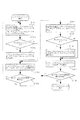
図1に、一般的なCPUを含むコンピュータの構成図を示す。
このコンピュータは、CPU10、メモリ20、I/O30、バス40を有する。CPU10は、バス40を介して、メモリ20、I/O30等と接続されている。CPU10は、レジスタファイル1、命令フェッチユニット2、命令キャッシュ3、演算論理ユニット(arithmetic logic unit、ALU)4、メモリアクセスユニット5、データキャッシュ6、バスインタフェースユニット7、演算バス11を備える。
【0015】
レジスタファイル1は、汎用レジスタ(GPR)、浮動小数点レジスタ(FPR)、プログラムカウンタ(PC)、ステータスレジスタ(SR)等の各種レジスタを含む。レジスタファイル1は、現在実行中のコンテキストを記憶する。命令キャッシュ3及びデータキャッシュ6は、例えば、SRAM、フリップフロップ(FF)等の素子が用いられ、アクセス、読み出し、書き込み等の処理速度が速いものの記憶容量が小さい。一方、CPU10外部のメモリ20は、SDRAM、DRAM等の素子が用いられ、アクセス、読み出し、書き込み等の処理速度がキャッシュより遅いものの記憶容量が大きい。
【0016】
ALU4は、局所性原理に従い、命令キャッシュ3、データキャッシュ6又はメモリ20から必要なデータ及び命令を利用する。ALU4は、命令キャッシュ3又はデータキャッシュ6に処理に必要な命令又はデータがあればそれを利用し、なければメモリ20にアクセスして必要な命令又はデータを得る。また、バスインターフェースユニット7は、命令キャッシュ3、メモリアクセスユニット5、データキャッシュ6とCPU外部のメモリ20、I/O30等をバス40を介して接続し、CPU内部と外部の間でデータの入出力行うユニットである。演算バス11は、レジスタファイル1、ALU4、メモリアクセスユニット5を並列に接続する演算パイプライン等のバスである。
【0017】
命令フェッチユニット2は、命令キャッシュ3へアドレス(Address)を出力し、命令キャッシュ3から命令(instruction)をフェッチし、デコードする。デコードされた命令に従い、ALU4がレジスタファイル1から必要なオペランドを読み出す。ALU4は、それに従い各種演算を行い、演算結果をレジスタファイル1に書き戻す。ロード(Load)又はストア(Store)等のメモリアクセス命令の場合、デコードされた命令に従い、メモリアクセスユニット5がオペランドを読み出す。
【0018】
メモリアクセスユニット5は、データキャッシュ6にアクセスしLoad又はStoreを行う。Store命令の場合、メモリアクセスユニット5は、アドレスとデータをデータキャッシュ6に送り、データをデータキャッシュ6に格納する。Load命令の場合、メモリアクセスユニット5は、アドレスをデータキャッシュ6に送りデータキャッシュ6からデータを読み出す。読み出したデータは、レジスタファイル1に書き戻される。このとき、データキャッシュ6に求めるデータがなければ、メモリ20からそれを読み出す。
【0019】
このような一般的な構成の場合、レジスタファイル1に記憶されたコンテキストの退避はStore命令を用いて行う。
【0020】
図2に、一般的なCPUでのコンテキストスイッチのフローチャートを示す。OS等のソフトウェアはStore命令を発行し、コンテキストスイッチを開始する。Store命令が発行されると、レジスタファイル1からデータが読み出され、メモリアクセスユニット5に送られる。そして、メモリアクセスユニット5は、データを格納するアドレスを計算し、データキャッシュ6にアクセスする(S101)。もし、データキャッシュミスが発生した場合(S103)、データキャッシュ6はメモリ20からキャッシュラインを読み込む(S105)。一方、データキャッシュミスが発生しなかった場合(S103)は、ステップS107へ進む。データキャッシュ6は、メモリアクセスユニット5から送られてきたデータを適当なアドレスで自身のキャッシュ内に格納する(S107)。OS等のソフトウェアは、このStore命令の処理を退避すべきレジスタの数だけ繰り返す。すなわち、全てのレジスタの内容の保存が完了していない場合は、ステップS101へ戻り処理を続け、全てのレジスタの内容の保存が完了した場合は、ステップS111へ進む(S109)。
【0021】
つぎに、OS等のソフトウェアは、新しく実行されるコンテキストの復帰を、Load命令を用いて行う。実行中のコンテキストの保存が完了すると、OS等のソフトウェアは、Load命令を発行する。Load命令が発行されると、メモリアクセスユニット5は、データを読み込むためのアドレスを計算し、データキャッシュ6をアクセスする(S111)。もし、データキャッシュミスが発生した場合(S113)、データキャッシュ6はメモリ20からキャッシュラインを読み込む(S115)。データキャッシュミスが発生しなかった場合(S113)は、ステップS117へ進む。メモリアクセスユニット5は、データキャッシュ6からデータが返ってくる(S117)と、それをレジスタファイル1に書き戻す。このLoad命令を復帰すべきレジスタの数だけ繰り返す。すなわち、全てのレジスタ内容の読み込みが完了した場合は、ステップS111へ戻り処理を続け、全てのレジスタ内容の読み込みが完了した場合は、コンテキストスイッチを終了する(S119)。
【0022】
2.コンテキスト切り替え装置を備えたCPU
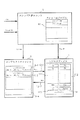
図3に、コンテキストキャッシュを用いたCPUを含むコンピュータの構成図を示す。
このCPU100は、レジスタファイル1、命令フェッチユニット2、命令キャッシュ3、ALU4、メモリアクセスユニット5、データキャッシュ6、バスインターフェースユニット7、コンテキストキャッシュ8、スレッド制御ユニット9、演算バス11、コンテキスト専用バス12を備える。演算バス11は、レジスタファイル1、ALU4、メモリアクセスユニット5にさらにスレッド制御ユニット9を並列に接続する演算パイプライン等のバスである。図1のCPU10の各部に対応して、同符号で示される各部の構成及び動作は、上述した通りである。
【0023】
コンテキストキャッシュ8は、SRAM、FF等の素子が用いられ、アクセス、読み出し、書き込み等の処理速度が速い。コンテキストキャッシュ8は、レジスタファイル1にコンテキストスイッチ専用バス12により接続され、コンテキストをキャッシュするために用いられる。スレッド制御ユニット8は、コンテキストキャッシュ8を制御するためのユニットであり、ALU4やメモリアクセスユニット5と並列に接続されている。なお、スレッドとは、一般に、OSがあるプロセス又はタスクを並列処理するため、プロセス又はタスクを分割した処理単位又は最小単位のことをいう。この際、プロセス又はタスクが分割されることなく、1プロセス又は1タスクが1スレッドとなる場合もある。コンテキストスイッチが起こった場合には、現在実行されているスレッドのコンテキスト(汎用レジスタ、浮動小数点レジスタ、プログラムカウンタ、ステータスレジスタ等)を退避し、新しく実行されるスレッドのコンテキストを復帰する必要がある。本実施の形態によるコンテキストキャッシュ8を用いたコンテキストスイッチの場合、コンテキストの退避と復帰は、レジスタファイル1とコンテキストキャッシュ8のデータをコンテキストスイッチ専用バス12を経て入れ替えるスワップ(Swap)命令を用いる。
【0024】
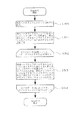
図4に、コンテキストキャッシュを用いたCPUでのコンテキストスイッチのフローチャートを示す。
OS等のソフトウェアは、Swap命令を発行し、コンテキストスイッチが開始する。Swap命令は、入れ替えるスレッドIDと共にスレッド制御ユニット9に発行される(S201)。スレッドIDは、コンテキストキャッシュ8に格納されているスレッドを一意に識別するために用いる。スレッド制御ユニット9は、コンテキストスイッチ専用バス12を経て、レジスタファイル1からコンテキストキャッシュ8へデータを退避すると同時並列に、コンテキストキャッシュ8からレジスタファイル1へ新しいスレッドのデータを送る。スレッド制御ユニット9は、送られてきたスレッドIDに基づいて自動的に必要な数だけレジスタファイル1内のデータとコンテキストキャッシュ8内のデータを入れ替える(S203)。このように、OS等のソフトウェアはSwap命令を発行するだけで、専用ハードウェアがコンテキストスイッチを開始し終了する。
【0025】
3.コンテキスト切り替え装置の詳細
図5に、コンテキスト切り替え装置の詳細構成図を示す。
レジスタファイル1は、汎用レジスタ111、浮動小数点レジスタ112、プログラムカウンタ113、ステータスレジスタ114を有する。コンテキストキャッシュ8は、コンテキストを格納するコンテキスト記憶領域8−1、8−2、・・・、8−nを所定のコンテキスト数有する。スレッド制御ユニット9は、オンチップのコンテキストキャッシュ8とレジスタファイル1を制御するためのコントローラである。スレッド制御ユニット9内部にはオンチップメモリに格納されているコンテキストを識別するためのスレッドIDを所定数保持するためのスレッドIDテーブル91を設ける。また、マルチスレッドプロセッサの場合は、レジスタファイル1が並列に複数存在することになる。
【0026】
図6に、Swap命令のフローチャートを示す。
コンテキストの切り替えは、例えばコンテキストスイッチハンドラー内でコンテキストスイッチ専用命令を用いることができる。OS等のソフトウェアが、Swap命令を発行すると、専用ハードウェアであるスレッド制御ユニット9が、そのSwap命令とスレッドIDを受けとる(S300)。スレッド制御ユニット9は、スレッドIDに基づいてスレッドIDテーブル91を検索し、コンテキストキャッシュ8をアクセスするため、入れ替えるべきスレッドのデータ(コンテキスト)が格納されているアドレスを計算し、また、レジスタファイル1をアクセスするため、レジスタIDを計算する(S301)。つぎに、全てのコンテキストのデータ(汎用レジスタ、ステータスレジスタなど)に対して、ステップS302からS304により繰返しループ処理が行われる。スレッド制御ユニット9は、計算したアドレスをもとにコンテキストキャッシュ8をアクセスし、新しく入れ替えるスレッドのデータ(コンテキスト)を読み出し、レジスタファイル1にそれを書き込む(S303)。それと同時又は並列に、スレッド制御ユニット9は、レジスタファイル1にアクセスし、今実行されているスレッドのデータ(コンテキスト)を読み出し、コンテキストキャッシュ8にそれを書き込む(S303)。このようにして、レジスタファイル1とコンテキストキャッシュ8は、それぞれのデータを入れ替える。全てのデータの入れ替えが終了していない場合(S304)、スレッド制御ユニット9は、コンテキストキャッシュ8をアクセスするアドレスとレジスタファイル1をアクセスするレジスタIDを1つずつ増やし、ステップS303に戻って処理を続ける(ステップS302及びS304による繰返しループ処理)。全てのデータの入れ替えが終了した場合(S304)、Swap命令を終了する。
【0027】
このように、スレッド制御ユニット9は、コンテキストキャッシュ8とレジスタファイル1のそれぞれのアドレスを連続的にインクリメントすることにより、必要な数だけデータを入れ替える。この際、従来のようにLoad及びStore命令を用いた場合には数百〜千数百クロックサイクルかかっていたコンテキストスイッチを、本実施の形態では、レジスタファイル1とコンテキストキャッシュ8のコンテキストスイッチ専用バス12によるデータ転送幅をレジスタのビット幅に比べて非常に広くすることによって、1クロックサイクル〜数クロックサイクル程度で実現する。具体的には、複数個のレジスタをまとめて1つの巨大なレジスタとして、その巨大なレジスタ毎に前記レジスタIDを割り当てるようにする。この際、全てのレジスタをまとめて1つの巨大なレジスタとした場合、1クロックサイクルでコンテキストスイッチを実現できる。
【0028】
スレッド制御ユニット9は、コンテキストを入れ替えるSwap命令の他に、コンテキストを退避するバックアップ(Backup)命令、コンテキストを復帰するリストア(Restore)命令を処理する。Backup命令の場合は、コンテキストキャッシュ8からレジスタファイル1へのコンテキストのデータ転送は行われず、レジスタファイル1からコンテキストキャッシュ8へのコンテキストのデータ転送のみが実行される。一方、Restore命令の場合は逆にレジスタファイル1からコンテキストキャッシュ8へのコンテキストのデータ転送は行われず、コンテキストキャッシュ8からレジスタファイル1へのコンテキストのデータ転送のみが実行される。
【0029】
つぎに、図7に、コンテキスト切り替え装置の実装に関する説明図を示す。
コンテキストキャッシュ8は、コンテキストをバックアップするオンチップのメモリであり、この例では2ポートを有し、CPUにオンチップで実装されている。この例では、コンテキストキャッシュ8は、書き込みポート82、読み出しポート83を備える。コンテキストキャッシュ8は、所定の複数コンテキスト分(例えば、32個等)の記憶領域を含むことができる。
【0030】
レジスタファイル1は、通常のリードポートとライトポートの他にコンテキスト切り替え用の専用ポート、即ちコンテキストスイッチ用読み出しポート17とコンテキストスイッチ用書き込みポート18を付加し、これらのポートにコンテキストを保持するための記憶装置を接続する。この例では、レジスタファイル1は、レジスタ読み出しポート15、レジスタ書き込みポート16、コンテキストスイッチ用読み出しポート17、コンテキストスイッチ用書き込みポート18を備える。レジスタ読み出しポート15は、レジスタファイル1からCPU内の装置へのレジスタの読み出しを、レジスタ書き込みポート16は、CPU内の装置からレジスタファイル1へのレジスタの書き込みを、コンテキストスイッチ用読み出しポート17は、レジスタファイル1からコンテキストファイル8へのレジスタの読み出しを、コンテキストスイッチ用書き込みポート18は、コンテキストファイル8からレジスタファイル1へのレジスタの書き込みを、それぞれ行うポートである。
【0031】
コンテキストの切り替えが発生した場合、OS等のソフトウェアはSwap命令を発行し、スレッド制御ユニットが、これらのポート17、18を通して中央演算装置のコンテキストキャッシュ8内のデータをレジスタファイル1に保持し、新しいコンテキストをこのレジスタファイル1から取り出す。また、レジスタファイル1とコンテキストキャッシュ8を接続するコンテキスト専用バス12−1、12−2の幅をレジスタファイル1のビット幅より広くすることにより、1度に入れ替えるデータの量を増やす。この例では、レジスタファイル1とオンチップメモリのコンテキストキャッシュ8とは、256ビットのコンテキストスイッチ専用バス12−1、12−2で繋がれる。また、コンテキストキャッシュ8として2ポートのオンチップメモリを用いることにより読み込みと書き出しを同時に行うことができる。そのため32ビット、32本の汎用レジスタは4クロックサイクルでコンテキストを入れ替えることができる。
なお、ビット数、記憶容量、ポート数等の各種パラメータは一例に過ぎず、適宜設定することができる。
【0032】
4.その他
本発明のコンテキスト切り替え方法又はコンテキスト切り替え装置・システムは、その各手順をコンピュータに実行させるためのコンテキスト切り替えプログラム、コンテキスト切り替えプログラムを記録したコンピュータ読み取り可能な記録媒体、コンテキスト切り替えプログラムを含みコンピュータの内部メモリにロード可能なプログラム製品、そのプログラムを含むサーバ等のコンピュータ、等により提供されることができる。
【0033】
【発明の効果】
本発明によると、以上のように、特に、リアルタイムOSなどコンテキストの切り替えが頻繁に発生するアプリケーションにおいて、コンテキストの切り替え(コンテキストスイッチ)によるオーバーヘッドを大幅に削減することができる。また、本発明によると、例えば、コンテキストを切り替える度に、コンテキストの保存と読み込みのためのメモリアクセスが、1サイクルから数サイクルで可能とするコンテキスト切り替え方法及び装置、中央演算装置、コンテキスト切り替えプログラムを記録したコンピュータ読み取り可能な記録媒体を提供することができる。
【0034】
また、本発明によると、特に、実時間処理システムのようにコンテキストスイッチが頻繁に起こるシステムにおいて、コンテキストスイッチにかかる時間を一定とし、実時間性の時間粒度を非常に小さくすることができる。
【図面の簡単な説明】
【図1】一般的なCPUを含むコンピュータの構成図。
【図2】一般的なCPUでのコンテキストスイッチのフローチャート。
【図3】コンテキストキャッシュを用いたCPUを含むコンピュータの構成図。
【図4】コンテキストキャッシュを用いたCPUでのコンテキストスイッチのフローチャート。
【図5】コンテキスト切り替え装置の詳細構成図。
【図6】Swap命令のフローチャート。
【図7】コンテキスト切り替え装置の実装に関する説明図。
【図8】コンテキスト切り替え動作の説明図。
【符号の説明】
1 レジスタファイル
2 命令フェッチユニット
3 命令キャッシュ
4 ALU
5 メモリアクセスユニット
6 データキャッシュ
7 バスインタフェースユニット
8 コンテキストキャッシュ
9 スレッド制御ユニット
10 CPU
11 演算バス
12 コンテキスト専用バス
12−1 コンテキスト専用バス
12−2 コンテキスト専用バス
15 レジスタ読み出しポート
16 レジスタ書き込みポート
17 コンテキストスイッチ用読み出しポート
18 コンテキストスイッチ用書き込みポート
20 メモリ
30 I/O
40 バス
8−1〜n コンテキストテーブル
91 スレッドIDテーブル
100 CPU
111 汎用レジスタ
112 浮動小数点レジスタ
113 プログラムカウンタ
114 ステータスレジスタ[0001]
TECHNICAL FIELD OF THE INVENTION
The present invention relates to a context switching method and apparatus, a central processing unit, a context switching program, and a computer-readable storage medium storing the context switching program, and more particularly to context switching in an OS such as a real-time operating system (RT-OS). The present invention relates to a context switching method and apparatus, a central processing unit, a context switching program, and a computer-readable storage medium storing the same, which can reduce overhead. Here, the context refers to information for execution of each thread stored in a storage unit (eg, a register file) such as a general-purpose register, a floating-point register, a program counter, and a status register, or a state currently being executed. Means
[0002]
[Prior art]
FIG. 8 is an explanatory diagram of the context switching operation.
This figure shows an example in which a plurality of contexts (threads) are switched and executed by one central processing unit. When the context is switched, the state of the context that has been executed (general purpose registers, floating point registers, program counters, status registers, etc .; hereinafter, it may be simply referred to as context) is saved, and the context to be newly executed is saved. It is necessary to read the status. The time required for the switching operation is called overhead, and the overhead occurs each time the context is switched.
[0003]
Conventionally, the following documents are cited as techniques for reducing the context switching time.
Patent Literature 1 discloses a multi-task processing device using a real-time operating system, in which a plurality of register banks occupied corresponding to each task are provided, and save / restore of contexts and the like are performed by switching the register banks. Techniques for reducing time are described.
[0004]
Further,
[Patent Document 1]
JP-A-07-141208
[Patent Document 2]
JP-A-09-212371
[0005]
[Problems to be solved by the invention]
In the conventional method, when the context is switched, the state of the context held in the central processing unit is stored one by one by a software such as an OS using a store instruction in a storage device outside the central processing unit. Thereafter, software such as the OS reads the new context from the storage device using the load instruction. That is, every time the context is switched, the memory access for saving and reading the context occurs from several hundred to several hundreds of cycles, which is a large overhead. Further, in the conventional method, since the context is saved and read by software using a load instruction and a store instruction, only one data can be handled at a time. Therefore, as the number of states to be stored increases, the time required for context switching also increases.
[0006]
In view of the above, an object of the present invention is to significantly reduce the overhead due to context switching (context switching), particularly in an application in which context switching frequently occurs, such as a real-time OS. The present invention provides, for example, a context switching method and apparatus, a central processing unit, a context switching program, and a memory that enable memory access for saving and reading of a context in one to several cycles every time a context is switched. It is an object of the present invention to provide a computer-readable storage medium.
[0007]
Another object of the present invention is to make the time required for context switching constant and to make the time granularity of real time extremely small, particularly in a system in which context switching occurs frequently, such as a real-time processing system.
[0008]
[Means for Solving the Problems]
The present invention, in particular,
1. Has a dedicated storage device (context cache) to hold the context,
2. A dedicated storage device (context cache) and a central processing unit (CPU) are connected using a dedicated bus having a bit width wider than that of the register;
This reduces the overhead required for context switching.
[0009]
According to a first solution of the present invention,
A context switching device that switches a plurality of contexts,
A register file in which a context relating to a thread to be executed in the arithmetic logic unit or the memory access unit is stored;
A context cache connected to the register file for caching context;
A context switch dedicated bus connecting the register file and the context cache;
A thread ID table for storing a thread identifier (thread ID) for identifying a context of the thread stored in the context cache; the thread ID table being connected in parallel with an arithmetic logic unit and a memory access unit; A thread control unit for controlling the transfer of context data to and from the register file;
With
The thread control unit includes:
When a context switch occurs, the thread ID table is searched based on the input switch instruction and a thread identifier (thread ID) to be newly replaced,
Obtain the address of the context cache in which the context to be newly replaced is stored and the register identifier of the register file in which the context being executed is stored,
Accessing the context cache based on the determined address, accessing the register file based on the determined register identifier, and replacing the context of the register file and / or the context cache via the context switch dedicated bus Execute evacuation or return
The context switching device
Is provided.
[0010]
According to a second solution of the present invention,
A context switching device as described above,
An instruction cache and a data cache for respectively caching instructions and data;
An instruction fetch unit for fetching and decoding instructions from the instruction cache;
An operation logic unit that performs various operations in accordance with the instructions stored in the register file and writes the operation result back to the register file;
A memory access unit that receives operands and instructions from the register file, accesses the data cache, and performs a load or store;
An arithmetic bus that connects the register file, the arithmetic logic unit, the memory access unit, and the thread control unit in parallel;
Central processing unit equipped with
Is provided.
[0011]
According to a third solution of the present invention,
A register file in which a context relating to a thread to be executed in the arithmetic logic unit or the memory access unit is stored;
A context cache connected to the register file for caching context;
A dedicated bus for context switch connecting the register file and the context cache;
A context switching method for switching a plurality of contexts using a context switching device having
When a context switch has occurred, a thread identifier (thread ID) for identifying the context of the thread stored in the context cache is set based on the input switching instruction and the thread identifier (thread ID) to be newly replaced. Searching the thread ID table to be stored,
Obtain the address of the context cache in which the context to be newly replaced is stored and the register identifier of the register file in which the context being executed is stored,
Accessing the context cache based on the determined address, accessing the register file based on the determined register identifier, and replacing the context of the register file and / or the context cache via the context switch dedicated bus Execute evacuation or return
The context switching method
Is provided.
[0012]
Further, according to a fourth solution of the present invention,
A register file in which a context relating to a thread to be executed in the arithmetic logic unit or the memory access unit is stored;
A context cache connected to the register file for caching context;
A dedicated bus for context switch connecting the register file and the context cache;
A computer-readable recording medium that records a context switching program in which a computer switches a plurality of contexts, using a context switching device including
When context switching occurs, a thread identifier (thread ID) for identifying the context of the thread stored in the context cache is set based on the input switching instruction and the newly replaced thread identifier (thread ID). Retrieving the thread ID table to be stored;
Determining the address of the context cache in which the context to be newly replaced is stored, and the register identifier of the register file in which the context being executed is stored;
Accessing the context cache based on the determined address, accessing the register file based on the determined register identifier, and replacing the context of the register file and / or the context cache via the context switch dedicated bus Performing evacuation or return; and
Switching program for causing a computer to execute the program, and a computer-readable recording medium recording the program
Is provided.
[0013]
BEST MODE FOR CARRYING OUT THE INVENTION
1. Related technology
Note that, as an example, the present embodiment is used as a context cache on a central processing unit of a Responsive Multi-Threaded (RMT) Processor for parallel distributed real-time control. Therefore, first, a computer including a CPU to which the present embodiment is related will be described.
[0014]
FIG. 1 shows a configuration diagram of a computer including a general CPU.
This computer has a
[0015]
The register file 1 includes various registers such as a general-purpose register (GPR), a floating-point register (FPR), a program counter (PC), and a status register (SR). The register file 1 stores the currently executing context. As the
[0016]
The
[0017]
The instruction fetch
[0018]
The
[0019]
In such a general configuration, the context stored in the register file 1 is saved using a Store instruction.
[0020]
FIG. 2 shows a flowchart of a context switch in a general CPU. Software such as an OS issues a Store instruction and starts a context switch. When the Store instruction is issued, data is read from the register file 1 and sent to the
[0021]
Next, software such as an OS uses a Load instruction to restore a newly executed context. When the saving of the running context is completed, the software such as the OS issues a Load instruction. When the Load instruction is issued, the
[0022]
2. CPU with context switching device
FIG. 3 shows a configuration diagram of a computer including a CPU using a context cache.
The
[0023]
The
[0024]
FIG. 4 shows a flowchart of a context switch in the CPU using the context cache.
Software such as an OS issues a Swap instruction, and a context switch starts. The Swap instruction is issued to the
[0025]
3. Details of the context switching device
FIG. 5 shows a detailed configuration diagram of the context switching device.
The register file 1 has a general-
[0026]
FIG. 6 shows a flowchart of the Swap instruction.
For context switching, for example, a context switch dedicated instruction can be used in a context switch handler. When software such as an OS issues a Swap instruction, the
[0027]
As described above, the
[0028]
The
[0029]
Next, FIG. 7 shows an explanatory diagram relating to the implementation of the context switching device.
The
[0030]
The register file 1 adds a dedicated port for context switching, that is, a
[0031]
When a context switch occurs, software such as the OS issues a Swap instruction, and the thread control unit holds the data in the
Note that various parameters such as the number of bits, the storage capacity, and the number of ports are merely examples, and can be set as appropriate.
[0032]
4. Other
A context switching method or a context switching device / system according to the present invention includes a context switching program for causing a computer to execute each procedure, a computer-readable recording medium on which the context switching program is recorded, and a computer internal memory including the context switching program. The program product can be provided by a computer such as a server including the program product that can be loaded into the program.
[0033]
【The invention's effect】
According to the present invention, as described above, the overhead caused by context switching (context switching) can be significantly reduced, particularly in applications in which context switching frequently occurs, such as a real-time OS. Further, according to the present invention, for example, each time a context is switched, a context switching method and apparatus, a central processing unit, and a context switching program that enable memory access for saving and reading of a context in one to several cycles are possible. A recorded computer-readable recording medium can be provided.
[0034]
Further, according to the present invention, particularly in a system in which context switching occurs frequently, such as a real-time processing system, the time required for context switching can be kept constant, and the time granularity of real-time processing can be made extremely small.
[Brief description of the drawings]
FIG. 1 is a configuration diagram of a computer including a general CPU.
FIG. 2 is a flowchart of a context switch in a general CPU.
FIG. 3 is a configuration diagram of a computer including a CPU using a context cache.
FIG. 4 is a flowchart of a context switch in a CPU using a context cache.
FIG. 5 is a detailed configuration diagram of a context switching device.
FIG. 6 is a flowchart of a Swap instruction.
FIG. 7 is an explanatory diagram relating to implementation of a context switching device.
FIG. 8 is an explanatory diagram of a context switching operation.
[Explanation of symbols]
1 Register file
2 Instruction fetch unit
3 Instruction cache
4 ALU
5 Memory access unit
6 Data cache
7 Bus interface unit
8 Context cache
9 Thread control unit
10 CPU
11 arithmetic bus
12 Bus dedicated to context
12-1 Context Dedicated Bus
12-2 Context Dedicated Bus
15 Register read port
16 Register write port
17 Read port for context switch
18 Context switch write port
20 memories
30 I / O
40 bus
8-1 to n context tables
91 Thread ID table
100 CPU
111 General-purpose register
112 floating point registers
113 Program counter
114 Status Register
Claims (15)
演算論理ユニット又はメモリアクセスユニットで実行すべきスレッドに関するコンテキストが記憶されたレジスタファイルと、
前記レジスタファイルに接続され、コンテキストをキャッシュするためのコンテキストキャッシュと、
前記レジスタファイルと前記コンテキストキャッシュを接続するコンテキストスイッチ専用バスと、
前記コンテキストキャッシュに記憶されているスレッドのコンテキストを識別するためのスレッド識別子(スレッドID)を記憶するスレッドIDテーブルを有し、演算論理ユニット及びメモリアクセスユニットと並列に接続され、前記コンテキストキャッシュと前記レジスタファイルとの間のデータ伝送を制御するスレッド制御ユニットと
を備え、
前記スレッド制御ユニットは、
コンテキストの切り替えが発生した場合、入力された切り替え命令と新たに入れ替えるスレッド識別子(スレッドID)に基づき前記スレッドIDテーブルを検索し、
新たに入れ替えるコンテキストが記憶されている前記コンテキストキャッシュのアドレスと、実行中のコンテキストが記憶されている前記レジスタファイルのレジスタ識別子を求め、
求めたアドレスに基付き前記コンテキストキャッシュをアクセスし、且つ、求めたレジスタ識別子に基付き前記レジスタファイルをアクセスし、前記レジスタファイル及び/又は前記コンテキストキャッシュのコンテキストを前記コンテキストスイッチ専用バスを介して入れ替え、退避又は復帰を実行する
前記コンテキスト切り替え装置。A context switching device that switches a plurality of contexts,
A register file in which a context relating to a thread to be executed in the arithmetic logic unit or the memory access unit is stored;
A context cache connected to the register file for caching context;
A context switch dedicated bus connecting the register file and the context cache;
A thread ID table for storing a thread identifier (thread ID) for identifying a context of the thread stored in the context cache; the thread ID table being connected in parallel with an arithmetic logic unit and a memory access unit; A thread control unit for controlling data transmission to and from the register file,
The thread control unit includes:
When context switching occurs, the thread ID table is searched based on the input switching instruction and a thread identifier (thread ID) to be newly replaced,
Obtain the address of the context cache in which the context to be newly replaced is stored and the register identifier of the register file in which the context being executed is stored,
Accessing the context cache based on the determined address, accessing the register file based on the determined register identifier, and replacing the context of the register file and / or the context cache via the context switch dedicated bus The context switching device that performs saving or restoring.
前記レジスタファイルは、リードポートとライトポート、コンテキストスイッチ用リードポートとライトポートを備え、
前記コンテキストキャッシュのリードポートとライトポートは、それぞれ前記コンテキストスイッチ専用バスにより前記レジスタファイルのコンテキストスイッチ用ライトポートとリードポートと接続されることを特徴とする請求項1に記載のコンテキスト切り替え装置。The context cache includes a read port and a write port,
The register file includes a read port and a write port, a read port and a write port for a context switch,
2. The context switching device according to claim 1, wherein a read port and a write port of the context cache are respectively connected to the context switch write port and the read port of the register file by the context switch dedicated bus.
命令及びデータをそれぞれキャッシュする命令キャッシュ及びデータキャッシュと、
前記命令キャッシュから命令をフェッチ及びデコードする命令フェッチユニットと、
レジスタファイルに記憶された命令に従い各種演算を行い、演算結果を前記レジスタファイルに書き戻す演算論理ユニットと、
前記レジスタファイルからオペランドと命令が送られ、前記データキャッシュをアクセスし、ロード又はストアを実行するメモリアクセスユニットと、
前記レジスタファイル、前記演算論理ユニット、前記メモリアクセスユニット及び前記スレッド制御ユニットを並列に接続する演算バスと、
を備えた中央演算装置。A context switching device according to any one of claims 1 to 7,
An instruction cache and a data cache for respectively caching instructions and data;
An instruction fetch unit for fetching and decoding instructions from the instruction cache;
An operation logic unit that performs various operations in accordance with the instructions stored in the register file and writes the operation result back to the register file;
A memory access unit that receives operands and instructions from the register file, accesses the data cache, and performs a load or store;
An arithmetic bus that connects the register file, the arithmetic logic unit, the memory access unit, and the thread control unit in parallel;
Central processing unit equipped with.
前記レジスタファイルに接続され、コンテキストをキャッシュするためのコンテキストキャッシュと、
前記レジスタファイルと前記コンテキストキャッシュを接続するコンテキストスイッチ専用バスと
を備えたコンテキスト切り替え装置を用い、複数のコンテキストを切り替えるコンテキスト切り替え方法であって、
コンテキストの切り替えが発生した場合、入力された切り替え命令と新たに入れ替えるスレッド識別子(スレッドID)に基付き、前記コンテキストキャッシュに記憶されているスレッドのコンテキストを識別するためのスレッド識別子(スレッドID)を記憶する前記スレッドIDテーブルを検索し、
新たに入れ替えるコンテキストが記憶されている前記コンテキストキャッシュのアドレスと、実行中のコンテキストが記憶されている前記レジスタファイルのレジスタ識別子を求め、
求めたアドレスに基付き前記コンテキストキャッシュをアクセスし、且つ、求めたレジスタ識別子に基付き前記レジスタファイルをアクセスし、前記レジスタファイル及び/又は前記コンテキストキャッシュのコンテキストを前記コンテキストスイッチ専用バスを介して入れ替え、退避又は復帰を実行する
前記コンテキスト切り替え方法。A register file in which a context relating to a thread to be executed in the arithmetic logic unit or the memory access unit is stored;
A context cache connected to the register file for caching context;
A context switching method for switching a plurality of contexts using a context switching device including the register file and a context switching dedicated bus connecting the context cache,
When a context switch has occurred, a thread identifier (thread ID) for identifying the context of the thread stored in the context cache is set based on the input switching instruction and the thread identifier (thread ID) to be newly replaced. Searching the thread ID table to be stored,
Obtain the address of the context cache in which the context to be newly replaced is stored and the register identifier of the register file in which the context being executed is stored,
Accessing the context cache based on the determined address, accessing the register file based on the determined register identifier, and replacing the context of the register file and / or the context cache via the context switch dedicated bus The context switching method for performing save or restore.
前記レジスタファイルに接続され、コンテキストをキャッシュするためのコンテキストキャッシュと、
前記レジスタファイルと前記コンテキストキャッシュを接続するコンテキスト専用バスと
を備えたコンテキスト切り替え装置を用い、コンピュータが複数のコンテキストを切り替えるコンテキスト切り替えプログラムであって、
コンテキストの切り替えが発生した場合、入力された切り替え命令と新たに入れ替えるスレッド識別子(スレッドID)に基付き、前記コンテキストキャッシュに格納されているスレッドのコンテキストを識別するためのスレッド識別子(スレッドID)を記憶する前記スレッドIDテーブルを検索するステップと、
新たに入れ替えるコンテキストが記憶されている前記コンテキストキャッシュのアドレスと、実行中のコンテキストが記憶されている前記レジスタファイルのレジスタ識別子を求めるステップと、
求めたアドレスに基付き前記コンテキストキャッシュをアクセスし、且つ、求めたレジスタ識別子に基付き前記レジスタファイルをアクセスし、前記レジスタファイル及び/又は前記コンテキストキャッシュのコンテキストを前記コンテキストスイッチ専用バスを介して入れ替え、退避又は復帰を実行するステップと
をコンピュータに実行させるためのコンテキスト切り替えプログラム。A register file in which a context relating to a thread to be executed in the arithmetic logic unit or the memory access unit is stored;
A context cache connected to the register file for caching context;
A context switching program that switches a plurality of contexts using a context switching device including the register file and a context-only bus that connects the context cache.
When context switching occurs, a thread identifier (thread ID) for identifying the context of the thread stored in the context cache is set based on the input switching instruction and the newly replaced thread identifier (thread ID). Retrieving the thread ID table to be stored;
Determining the address of the context cache in which the context to be newly replaced is stored, and the register identifier of the register file in which the context being executed is stored;
Accessing the context cache based on the determined address, accessing the register file based on the determined register identifier, and replacing the context of the register file and / or the context cache via the context switch dedicated bus , A context switching program for causing a computer to execute a step of performing saving or restoring.
前記レジスタファイルに接続され、コンテキストをキャッシュするためのコンテキストキャッシュと、
前記レジスタファイルと前記コンテキストキャッシュを接続するコンテキストスイッチ専用バスと
を備えたコンテキスト切り替え装置を用い、コンピュータが複数のコンテキストを切り替えるコンテキスト切り替えプログラムを記録したコンピュータ読み取り可能な記録媒体であって、
コンテキストの切り替えが発生した場合、入力された切り替え命令と新たに入れ替えるスレッド識別子(スレッドID)に基付き、前記コンテキストキャッシュに格納されているスレッドのコンテキストを識別するためのスレッド識別子(スレッドID)を記憶する前記スレッドIDテーブルを検索するステップと、
新たに入れ替えるコンテキストが記憶されている前記コンテキストキャッシュのアドレスと、実行中のコンテキストが記憶されている前記レジスタファイルのレジスタ識別子を求めるステップと、
求めたアドレスに基付き前記コンテキストキャッシュをアクセスし、且つ、求めたレジスタ識別子に基付き前記レジスタファイルをアクセスし、前記レジスタファイル及び/又は前記コンテキストキャッシュのコンテキストを前記コンテキストスイッチ専用バスを介して入れ替え、退避又は復帰を実行するステップと
をコンピュータに実行させるためのコンテキスト切り替えプログラムを記録したコンピュータ読み取り可能な記録媒体。A register file in which a context relating to a thread to be executed in the arithmetic logic unit or the memory access unit is stored;
A context cache connected to the register file for caching context;
A computer-readable recording medium recording a context switching program that switches a plurality of contexts using a context switching device including the register file and a context switching dedicated bus that connects the context cache.
When context switching occurs, a thread identifier (thread ID) for identifying the context of the thread stored in the context cache is set based on the input switching instruction and the newly replaced thread identifier (thread ID). Retrieving the thread ID table to be stored;
Determining the address of the context cache in which the context to be newly replaced is stored, and the register identifier of the register file in which the context being executed is stored;
Accessing the context cache based on the determined address, accessing the register file based on the determined register identifier, and replacing the context of the register file and / or the context cache via the context switch dedicated bus , A computer-readable recording medium recording a context switching program for causing a computer to execute a step of performing a save or a return.
Priority Applications (4)
| Application Number | Priority Date | Filing Date | Title |
|---|---|---|---|
| JP2003003038A JP2004220070A (en) | 2003-01-09 | 2003-01-09 | Context switching method and device, central processing unit, context switching program and computer-readable storage medium storing it |
| EP03780720A EP1582980B1 (en) | 2003-01-09 | 2003-12-11 | Context switching method, device, program, recording medium, and central processing unit |
| US10/541,187 US8020169B2 (en) | 2003-01-09 | 2003-12-11 | Context switching system having context cache and a register file for the save and restore context operation |
| PCT/JP2003/015838 WO2004063925A1 (en) | 2003-01-09 | 2003-12-11 | Context switching method, device, program, recording medium, and central processing unit |
Applications Claiming Priority (1)
| Application Number | Priority Date | Filing Date | Title |
|---|---|---|---|
| JP2003003038A JP2004220070A (en) | 2003-01-09 | 2003-01-09 | Context switching method and device, central processing unit, context switching program and computer-readable storage medium storing it |
Publications (1)
| Publication Number | Publication Date |
|---|---|
| JP2004220070A true JP2004220070A (en) | 2004-08-05 |
Family
ID=32708889
Family Applications (1)
| Application Number | Title | Priority Date | Filing Date |
|---|---|---|---|
| JP2003003038A Pending JP2004220070A (en) | 2003-01-09 | 2003-01-09 | Context switching method and device, central processing unit, context switching program and computer-readable storage medium storing it |
Country Status (4)
| Country | Link |
|---|---|
| US (1) | US8020169B2 (en) |
| EP (1) | EP1582980B1 (en) |
| JP (1) | JP2004220070A (en) |
| WO (1) | WO2004063925A1 (en) |
Cited By (6)
| Publication number | Priority date | Publication date | Assignee | Title |
|---|---|---|---|---|
| EP1736890A2 (en) | 2005-06-03 | 2006-12-27 | NEC Electronics Corporation | Stream processor including DMA controller used in data processing apparatus |
| WO2008023426A1 (en) * | 2006-08-24 | 2008-02-28 | Netcleus Systems Corporation | Task processing device |
| US8327379B2 (en) | 2006-08-24 | 2012-12-04 | Kernelon Silicon Inc. | Method for switching a selected task to be executed according with an output from task selecting circuit |
| JP2013536524A (en) * | 2010-08-23 | 2013-09-19 | エンパイア テクノロジー ディベロップメント エルエルシー | Context switch |
| JP2015534188A (en) * | 2012-09-28 | 2015-11-26 | インテル・コーポレーション | New instructions and highly efficient micro-architecture that allow immediate context switching for user-level threading |
| US20170060582A1 (en) * | 2015-09-01 | 2017-03-02 | Freescale Semiconductor, Inc. | Arbitrary instruction execution from context memory |
Families Citing this family (67)
| Publication number | Priority date | Publication date | Assignee | Title |
|---|---|---|---|---|
| US20050132363A1 (en) * | 2003-12-16 | 2005-06-16 | Vijay Tewari | Method, apparatus and system for optimizing context switching between virtual machines |
| US8427490B1 (en) | 2004-05-14 | 2013-04-23 | Nvidia Corporation | Validating a graphics pipeline using pre-determined schedules |
| JP4204522B2 (en) * | 2004-07-07 | 2009-01-07 | 株式会社東芝 | Microprocessor |
| US8624906B2 (en) | 2004-09-29 | 2014-01-07 | Nvidia Corporation | Method and system for non stalling pipeline instruction fetching from memory |
| US8493396B2 (en) | 2004-11-15 | 2013-07-23 | Nvidia Corporation | Multidimensional datapath processing in a video processor |
| US9606821B2 (en) | 2004-12-17 | 2017-03-28 | Intel Corporation | Virtual environment manager for creating and managing virtual machine environments |
| US9092170B1 (en) | 2005-10-18 | 2015-07-28 | Nvidia Corporation | Method and system for implementing fragment operation processing across a graphics bus interconnect |
| US20070294693A1 (en) * | 2006-06-16 | 2007-12-20 | Microsoft Corporation | Scheduling thread execution among a plurality of processors based on evaluation of memory access data |
| US8219789B2 (en) * | 2007-03-14 | 2012-07-10 | XMOS Ltd. | Interface processor |
| US8683126B2 (en) | 2007-07-30 | 2014-03-25 | Nvidia Corporation | Optimal use of buffer space by a storage controller which writes retrieved data directly to a memory |
| US9024957B1 (en) | 2007-08-15 | 2015-05-05 | Nvidia Corporation | Address independent shader program loading |
| US8698819B1 (en) | 2007-08-15 | 2014-04-15 | Nvidia Corporation | Software assisted shader merging |
| US8411096B1 (en) | 2007-08-15 | 2013-04-02 | Nvidia Corporation | Shader program instruction fetch |
| US8659601B1 (en) | 2007-08-15 | 2014-02-25 | Nvidia Corporation | Program sequencer for generating indeterminant length shader programs for a graphics processor |
| US9710384B2 (en) | 2008-01-04 | 2017-07-18 | Micron Technology, Inc. | Microprocessor architecture having alternative memory access paths |
| US8972958B1 (en) | 2012-10-23 | 2015-03-03 | Convey Computer | Multistage development workflow for generating a custom instruction set reconfigurable processor |
| JP2009098819A (en) * | 2007-10-15 | 2009-05-07 | Elpida Memory Inc | Memory system, control method for memory system, and computer system |
| US9064333B2 (en) | 2007-12-17 | 2015-06-23 | Nvidia Corporation | Interrupt handling techniques in the rasterizer of a GPU |
| US8780123B2 (en) | 2007-12-17 | 2014-07-15 | Nvidia Corporation | Interrupt handling techniques in the rasterizer of a GPU |
| US8681861B2 (en) | 2008-05-01 | 2014-03-25 | Nvidia Corporation | Multistandard hardware video encoder |
| US8923385B2 (en) | 2008-05-01 | 2014-12-30 | Nvidia Corporation | Rewind-enabled hardware encoder |
| US8489851B2 (en) | 2008-12-11 | 2013-07-16 | Nvidia Corporation | Processing of read requests in a memory controller using pre-fetch mechanism |
| US10055251B1 (en) * | 2009-04-22 | 2018-08-21 | The Trustees Of Columbia University In The City Of New York | Methods, systems, and media for injecting code into embedded devices |
| US8578138B2 (en) * | 2009-08-31 | 2013-11-05 | Intel Corporation | Enabling storage of active state in internal storage of processor rather than in SMRAM upon entry to system management mode |
| US9392017B2 (en) | 2010-04-22 | 2016-07-12 | The Trustees Of Columbia University In The City Of New York | Methods, systems, and media for inhibiting attacks on embedded devices |
| US8725993B2 (en) | 2011-02-23 | 2014-05-13 | International Business Machines Corporation | Thread transition management |
| WO2012145816A1 (en) * | 2011-04-26 | 2012-11-01 | Research In Motion Limited | System and method for operating a processor |
| US20130070513A1 (en) * | 2011-09-16 | 2013-03-21 | Advanced Micro Devices, Inc. | Method and apparatus for direct backup of memory circuits |
| US9159409B2 (en) | 2011-09-16 | 2015-10-13 | Advanced Micro Devices, Inc. | Method and apparatus for providing complimentary state retention |
| US10078515B2 (en) * | 2011-10-03 | 2018-09-18 | International Business Machines Corporation | Tracking operand liveness information in a computer system and performing function based on the liveness information |
| DE102011119004A1 (en) * | 2011-11-19 | 2013-05-23 | Diehl Aerospace Gmbh | Graphics processing device, display device for an aircraft cockpit and method for displaying graphics data |
| US9442759B2 (en) * | 2011-12-09 | 2016-09-13 | Nvidia Corporation | Concurrent execution of independent streams in multi-channel time slice groups |
| KR102132501B1 (en) | 2012-02-15 | 2020-07-09 | 더 트러스티이스 오브 콜롬비아 유니버시티 인 더 시티 오브 뉴욕 | Methods, systems, and media for inhibiting attacks on embedded devices |
| US10430190B2 (en) * | 2012-06-07 | 2019-10-01 | Micron Technology, Inc. | Systems and methods for selectively controlling multithreaded execution of executable code segments |
| US9170968B2 (en) * | 2012-09-27 | 2015-10-27 | Intel Corporation | Device, system and method of multi-channel processing |
| US9250954B2 (en) * | 2013-01-17 | 2016-02-02 | Xockets, Inc. | Offload processor modules for connection to system memory, and corresponding methods and systems |
| US9652284B2 (en) | 2013-10-01 | 2017-05-16 | Qualcomm Incorporated | GPU divergence barrier |
| US9507731B1 (en) * | 2013-10-11 | 2016-11-29 | Rambus Inc. | Virtualized cache memory |
| CN103713882A (en) * | 2013-12-20 | 2014-04-09 | 华为技术有限公司 | Method and device for swapping data in memory |
| US11200058B2 (en) | 2014-05-07 | 2021-12-14 | Qualcomm Incorporated | Dynamic load balancing of hardware threads in clustered processor cores using shared hardware resources, and related circuits, methods, and computer-readable media |
| US10657262B1 (en) * | 2014-09-28 | 2020-05-19 | Red Balloon Security, Inc. | Method and apparatus for securing embedded device firmware |
| US10496433B2 (en) * | 2014-11-24 | 2019-12-03 | Red Hat, Inc. | Modification of context saving functions |
| US9817664B2 (en) | 2015-02-19 | 2017-11-14 | Apple Inc. | Register caching techniques for thread switches |
| US9323575B1 (en) | 2015-02-26 | 2016-04-26 | Freescale Semiconductor, Inc. | Systems and methods for improving data restore overhead in multi-tasking environments |
| GB2536211B (en) * | 2015-03-04 | 2021-06-16 | Advanced Risc Mach Ltd | An apparatus and method for executing a plurality of threads |
| US10019283B2 (en) * | 2015-06-22 | 2018-07-10 | Advanced Micro Devices, Inc. | Predicting a context portion to move between a context buffer and registers based on context portions previously used by at least one other thread |
| US10423418B2 (en) | 2015-11-30 | 2019-09-24 | International Business Machines Corporation | Method for maintaining a branch prediction history table |
| US10489296B2 (en) | 2016-09-22 | 2019-11-26 | International Business Machines Corporation | Quality of cache management in a computer |
| US10423415B2 (en) | 2017-04-01 | 2019-09-24 | Intel Corporation | Hierarchical general register file (GRF) for execution block |
| US10540184B2 (en) | 2017-04-18 | 2020-01-21 | International Business Machines Corporation | Coalescing store instructions for restoration |
| US10489382B2 (en) | 2017-04-18 | 2019-11-26 | International Business Machines Corporation | Register restoration invalidation based on a context switch |
| US10564977B2 (en) | 2017-04-18 | 2020-02-18 | International Business Machines Corporation | Selective register allocation |
| US10963261B2 (en) | 2017-04-18 | 2021-03-30 | International Business Machines Corporation | Sharing snapshots across save requests |
| US10552164B2 (en) | 2017-04-18 | 2020-02-04 | International Business Machines Corporation | Sharing snapshots between restoration and recovery |
| US10740108B2 (en) | 2017-04-18 | 2020-08-11 | International Business Machines Corporation | Management of store queue based on restoration operation |
| US11010192B2 (en) * | 2017-04-18 | 2021-05-18 | International Business Machines Corporation | Register restoration using recovery buffers |
| US10838733B2 (en) | 2017-04-18 | 2020-11-17 | International Business Machines Corporation | Register context restoration based on rename register recovery |
| US10572265B2 (en) | 2017-04-18 | 2020-02-25 | International Business Machines Corporation | Selecting register restoration or register reloading |
| US10782979B2 (en) | 2017-04-18 | 2020-09-22 | International Business Machines Corporation | Restoring saved architected registers and suppressing verification of registers to be restored |
| US10545766B2 (en) | 2017-04-18 | 2020-01-28 | International Business Machines Corporation | Register restoration using transactional memory register snapshots |
| US10649785B2 (en) | 2017-04-18 | 2020-05-12 | International Business Machines Corporation | Tracking changes to memory via check and recovery |
| US10684857B2 (en) | 2018-02-01 | 2020-06-16 | International Business Machines Corporation | Data prefetching that stores memory addresses in a first table and responsive to the occurrence of loads corresponding to the memory addresses stores the memory addresses in a second table |
| US10871992B2 (en) * | 2018-05-30 | 2020-12-22 | Texas Instruments Incorporated | Level two first-in-first-out transmission |
| JP2019219984A (en) * | 2018-06-21 | 2019-12-26 | ルネサスエレクトロニクス株式会社 | Memory module |
| TWI703500B (en) * | 2019-02-01 | 2020-09-01 | 睿寬智能科技有限公司 | Method for shortening content exchange time and its semiconductor device |
| CN111581124A (en) * | 2019-02-19 | 2020-08-25 | 睿宽智能科技有限公司 | Method for shortening text exchange time and semiconductor device thereof |
| US11775303B2 (en) * | 2020-11-12 | 2023-10-03 | Electronics And Telecommunications Research Institute | Computing accelerator for processing multiple-type instruction and operation method thereof |
Family Cites Families (22)
| Publication number | Priority date | Publication date | Assignee | Title |
|---|---|---|---|---|
| JPH039431A (en) | 1989-06-07 | 1991-01-17 | Nec Corp | Interruption processing system |
| JPH0683639A (en) | 1992-09-02 | 1994-03-25 | Mitsubishi Electric Corp | Register device |
| US5892944A (en) * | 1993-07-20 | 1999-04-06 | Kabushiki Kaisha Toshiba | Program execution and operation right management system suitable for single virtual memory scheme |
| JP3644042B2 (en) | 1993-11-15 | 2005-04-27 | ソニー株式会社 | Multitask processing device |
| US6205467B1 (en) * | 1995-11-14 | 2001-03-20 | Advanced Micro Devices, Inc. | Microprocessor having a context save unit for saving context independent from interrupt requests |
| JPH09212371A (en) | 1996-02-07 | 1997-08-15 | Nec Corp | Register saving and restoring system |
| JPH1011301A (en) * | 1996-06-25 | 1998-01-16 | Masaharu Imai | Multitask processor and multitask processing control method |
| JPH1063517A (en) | 1996-08-22 | 1998-03-06 | Nippon Telegr & Teleph Corp <Ntt> | Real time information processing method and its device |
| US6233599B1 (en) * | 1997-07-10 | 2001-05-15 | International Business Machines Corporation | Apparatus and method for retrofitting multi-threaded operations on a computer by partitioning and overlapping registers |
| JPH1139171A (en) | 1997-07-18 | 1999-02-12 | Masaharu Imai | Multitask processor, multitask processing control method and control program storing medium |
| US6076157A (en) * | 1997-10-23 | 2000-06-13 | International Business Machines Corporation | Method and apparatus to force a thread switch in a multithreaded processor |
| US6018759A (en) * | 1997-12-22 | 2000-01-25 | International Business Machines Corporation | Thread switch tuning tool for optimal performance in a computer processor |
| US6986141B1 (en) * | 1998-03-10 | 2006-01-10 | Agere Systems Inc. | Context controller having instruction-based time slice task switching capability and processor employing the same |
| US6378065B1 (en) | 1998-04-27 | 2002-04-23 | Infineon Technologies North America Corp. | Apparatus with context switching capability |
| US6408325B1 (en) * | 1998-05-06 | 2002-06-18 | Sun Microsystems, Inc. | Context switching technique for processors with large register files |
| JP2000076079A (en) | 1998-09-03 | 2000-03-14 | Nec Corp | Microcomputer |
| US6401155B1 (en) | 1998-12-22 | 2002-06-04 | Philips Electronics North America Corporation | Interrupt/software-controlled thread processing |
| JP3880739B2 (en) | 1999-02-25 | 2007-02-14 | 三菱電機株式会社 | Operating system processing method and operating system processing method |
| US6351808B1 (en) * | 1999-05-11 | 2002-02-26 | Sun Microsystems, Inc. | Vertically and horizontally threaded processor with multidimensional storage for storing thread data |
| GB2372348B (en) * | 2001-02-20 | 2003-06-04 | Siroyan Ltd | Context preservation |
| KR20030088031A (en) | 2001-02-27 | 2003-11-15 | 인터내셔널 비지네스 머신즈 코포레이션 | Microprocessor and Instruction Execution Order Scheduling Method |
| US6526491B2 (en) * | 2001-03-22 | 2003-02-25 | Sony Corporation Entertainment Inc. | Memory protection system and method for computer architecture for broadband networks |
-
2003
- 2003-01-09 JP JP2003003038A patent/JP2004220070A/en active Pending
- 2003-12-11 EP EP03780720A patent/EP1582980B1/en not_active Expired - Fee Related
- 2003-12-11 US US10/541,187 patent/US8020169B2/en not_active Expired - Fee Related
- 2003-12-11 WO PCT/JP2003/015838 patent/WO2004063925A1/en active Application Filing
Cited By (9)
| Publication number | Priority date | Publication date | Assignee | Title |
|---|---|---|---|---|
| EP1736890A2 (en) | 2005-06-03 | 2006-12-27 | NEC Electronics Corporation | Stream processor including DMA controller used in data processing apparatus |
| WO2008023426A1 (en) * | 2006-08-24 | 2008-02-28 | Netcleus Systems Corporation | Task processing device |
| US8327379B2 (en) | 2006-08-24 | 2012-12-04 | Kernelon Silicon Inc. | Method for switching a selected task to be executed according with an output from task selecting circuit |
| US9342350B2 (en) | 2006-08-24 | 2016-05-17 | Renesas Electronics Corporation | System for selecting a task to be executed according to an output from a task control circuit |
| US9753729B2 (en) | 2006-08-24 | 2017-09-05 | Renesas Electronics Corporation | System for selecting a task to be executed according to an output from a task control circuit |
| JP2013536524A (en) * | 2010-08-23 | 2013-09-19 | エンパイア テクノロジー ディベロップメント エルエルシー | Context switch |
| JP2015534188A (en) * | 2012-09-28 | 2015-11-26 | インテル・コーポレーション | New instructions and highly efficient micro-architecture that allow immediate context switching for user-level threading |
| US20170060582A1 (en) * | 2015-09-01 | 2017-03-02 | Freescale Semiconductor, Inc. | Arbitrary instruction execution from context memory |
| US9785538B2 (en) * | 2015-09-01 | 2017-10-10 | Nxp Usa, Inc. | Arbitrary instruction execution from context memory |
Also Published As
| Publication number | Publication date |
|---|---|
| WO2004063925A1 (en) | 2004-07-29 |
| EP1582980A1 (en) | 2005-10-05 |
| US8020169B2 (en) | 2011-09-13 |
| US20070022428A1 (en) | 2007-01-25 |
| EP1582980B1 (en) | 2012-03-21 |
| EP1582980A4 (en) | 2008-03-12 |
Similar Documents
| Publication | Publication Date | Title |
|---|---|---|
| JP2004220070A (en) | Context switching method and device, central processing unit, context switching program and computer-readable storage medium storing it | |
| US20230052630A1 (en) | Processor having multiple cores, shared core extension logic, and shared core extension utilization instructions | |
| US7590774B2 (en) | Method and system for efficient context swapping | |
| US6671827B2 (en) | Journaling for parallel hardware threads in multithreaded processor | |
| US8074026B2 (en) | Scatter-gather intelligent memory architecture for unstructured streaming data on multiprocessor systems | |
| US8539485B2 (en) | Polling using reservation mechanism | |
| KR100613923B1 (en) | Context pipelines | |
| US20140108743A1 (en) | Store data forwarding with no memory model restrictions | |
| KR20010033147A (en) | Processor having multiple datapath instances | |
| JP2007242003A (en) | Technique for using memory attributes | |
| WO2007002408A2 (en) | Computer processor pipeline with shadow registers for context switching, and method | |
| CN110647404A (en) | System, apparatus and method for barrier synchronization in a multithreaded processor | |
| JP2004512599A (en) | Digital signal processor | |
| CN110659115A (en) | Multi-threaded processor core with hardware assisted task scheduling | |
| US11868306B2 (en) | Processing-in-memory concurrent processing system and method | |
| WO2023103392A1 (en) | Method and apparatus for storage management, medium, program product, and system | |
| JP3646137B2 (en) | Instruction issuing method and apparatus, central processing unit, instruction issuing program, and computer-readable storage medium storing the same | |
| WO2023103397A1 (en) | Method for storage management, medium, program product, system, and apparatus | |
| JP2011192305A (en) | Semiconductor signal processor | |
| JP2010204933A (en) | Cache system and computer using the same | |
| JPH04156617A (en) | Interruption/exception control system | |
| JPH0384636A (en) | Computer control system | |
| JPH06309225A (en) | Information processor |
Legal Events
| Date | Code | Title | Description |
|---|---|---|---|
| A02 | Decision of refusal |
Free format text: JAPANESE INTERMEDIATE CODE: A02 Effective date: 20040831 |
|
| A521 | Request for written amendment filed |
Free format text: JAPANESE INTERMEDIATE CODE: A523 Effective date: 20041020 |
|
| A521 | Request for written amendment filed |
Free format text: JAPANESE INTERMEDIATE CODE: A821 Effective date: 20041201 |
|
| A911 | Transfer to examiner for re-examination before appeal (zenchi) |
Free format text: JAPANESE INTERMEDIATE CODE: A911 Effective date: 20050106 |
|
| A912 | Re-examination (zenchi) completed and case transferred to appeal board |
Free format text: JAPANESE INTERMEDIATE CODE: A912 Effective date: 20050428 |
|
| A521 | Request for written amendment filed |
Free format text: JAPANESE INTERMEDIATE CODE: A523 Effective date: 20071101 |